ID Heikenfeld p26-30 v4 041497 - Nanoelectronics Laboratory · The fundamental mechanism behind all...
6
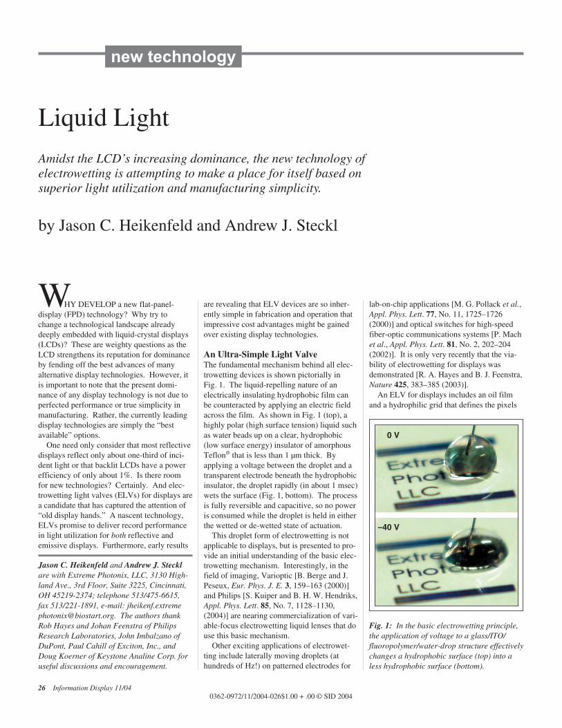
W HY DEVELOP a new flat-panel- display (FPD) technology? Why try to change a technological landscape already deeply embedded with liquid-crystal displays (LCDs)? These are weighty questions as the LCD strengthens its reputation for dominance by fending off the best advances of many alternative display technologies. However, it is important to note that the present domi- nance of any display technology is not due to perfected performance or true simplicity in manufacturing. Rather, the currently leading display technologies are simply the “best available” options. One need only consider that most reflective displays reflect only about one-third of inci- dent light or that backlit LCDs have a power efficiency of only about 1%. Is there room for new technologies? Certainly. And elec- trowetting light valves (ELVs) for displays are a candidate that has captured the attention of “old display hands.” A nascent technology, ELVs promise to deliver record performance in light utilization for both reflective and emissive displays. Furthermore, early results are revealing that ELV devices are so inher- ently simple in fabrication and operation that impressive cost advantages might be gained over existing display technologies. An Ultra-Simple Light Valve The fundamental mechanism behind all elec- trowetting devices is shown pictorially in Fig. 1. The liquid-repelling nature of an electrically insulating hydrophobic film can be counteracted by applying an electric field across the film. As shown in Fig. 1 (top), a highly polar (high surface tension) liquid such as water beads up on a clear, hydrophobic (low surface energy) insulator of amorphous Teflon ® that is less than 1 μm thick. By applying a voltage between the droplet and a transparent electrode beneath the hydrophobic insulator, the droplet rapidly (in about 1 msec) wets the surface (Fig. 1, bottom). The process is fully reversible and capacitive, so no power is consumed while the droplet is held in either the wetted or de-wetted state of actuation. This droplet form of electrowetting is not applicable to displays, but is presented to pro- vide an initial understanding of the basic elec- trowetting mechanism. Interestingly, in the field of imaging, Varioptic [B. Berge and J. Peseux, Eur. Phys. J. E. 3, 159–163 (2000)] and Philips [S. Kuiper and B. H. W. Hendriks, Appl. Phys. Lett. 85, No. 7, 1128–1130, (2004)] are nearing commercialization of vari- able-focus electrowetting liquid lenses that do use this basic mechanism. Other exciting applications of electrowet- ting include laterally moving droplets (at hundreds of Hz!) on patterned electrodes for lab-on-chip applications [M. G. Pollack et al., Appl. Phys. Lett. 77, No. 11, 1725–1726 (2000)] and optical switches for high-speed fiber-optic communications systems [P. Mach et al., Appl. Phys. Lett. 81, No. 2, 202–204 (2002)]. It is only very recently that the via- bility of electrowetting for displays was demonstrated [R. A. Hayes and B. J. Feenstra, Nature 425, 383–385 (2003)]. An ELV for displays includes an oil film and a hydrophilic grid that defines the pixels Liquid Light Amidst the LCD’s increasing dominance, the new technology of electrowetting is attempting to make a place for itself based on superior light utilization and manufacturing simplicity. by Jason C. Heikenfeld and Andrew J. Steckl Jason C. Heikenfeld and Andrew J. Steckl are with Extreme Photonix, LLC, 3130 High- land Ave., 3rd Floor, Suite 3225, Cincinnati, OH 45219-2374; telephone 513/475-6615, fax 513/221-1891, e-mail: jheikenf.extreme [email protected]. The authors thank Rob Hayes and Johan Feenstra of Philips Research Laboratories, John Imbalzano of DuPont, Paul Cahill of Exciton, Inc., and Doug Koerner of Keystone Analine Corp. for useful discussions and encouragement. 26 Information Display 11/04 0362-0972/11/2004-026$1.00 + .00 © SID 2004 new technology Fig. 1: In the basic electrowetting principle, the application of voltage to a glass/ITO/ fluoropolymer/water-drop structure effectively changes a hydrophobic surface (top) into a less hydrophobic surface (bottom). 0 V –40 V
Transcript of ID Heikenfeld p26-30 v4 041497 - Nanoelectronics Laboratory · The fundamental mechanism behind all...
WHY DEVELOP a new flat-panel-display (FPD) technology? Why try tochange a technological landscape alreadydeeply embedded with liquid-crystal displays(LCDs)? These are weighty questions as theLCD strengthens its reputation for dominanceby fending off the best advances of manyalternative display technologies. However, itis important to note that the present domi-nance of any display technology is not due toperfected performance or true simplicity inmanufacturing. Rather, the currently leadingdisplay technologies are simply the “bestavailable” options.
One need only consider that most reflectivedisplays reflect only about one-third of inci-dent light or that backlit LCDs have a powerefficiency of only about 1%. Is there room for new technologies? Certainly. And elec-trowetting light valves (ELVs) for displays area candidate that has captured the attention of“old display hands.” A nascent technology,ELVs promise to deliver record performancein light utilization for both reflective andemissive displays. Furthermore, early results
are revealing that ELV devices are so inher-ently simple in fabrication and operation thatimpressive cost advantages might be gainedover existing display technologies.
An Ultra-Simple Light ValveThe fundamental mechanism behind all elec-trowetting devices is shown pictorially in Fig. 1. The liquid-repelling nature of an electrically insulating hydrophobic film canbe counteracted by applying an electric fieldacross the film. As shown in Fig. 1 (top), ahighly polar (high surface tension) liquid suchas water beads up on a clear, hydrophobic(low surface energy) insulator of amorphousTeflon® that is less than 1 µm thick. Byapplying a voltage between the droplet and atransparent electrode beneath the hydrophobicinsulator, the droplet rapidly (in about 1 msec)wets the surface (Fig. 1, bottom). The processis fully reversible and capacitive, so no poweris consumed while the droplet is held in eitherthe wetted or de-wetted state of actuation.
This droplet form of electrowetting is notapplicable to displays, but is presented to pro-vide an initial understanding of the basic elec-trowetting mechanism. Interestingly, in thefield of imaging, Varioptic [B. Berge and J.Peseux, Eur. Phys. J. E. 3, 159–163 (2000)]and Philips [S. Kuiper and B. H. W. Hendriks,Appl. Phys. Lett. 85, No. 7, 1128–1130,(2004)] are nearing commercialization of vari-able-focus electrowetting liquid lenses that douse this basic mechanism.
Other exciting applications of electrowet-ting include laterally moving droplets (at hundreds of Hz!) on patterned electrodes for
lab-on-chip applications [M. G. Pollack et al.,Appl. Phys. Lett. 77, No. 11, 1725–1726(2000)] and optical switches for high-speedfiber-optic communications systems [P. Machet al., Appl. Phys. Lett. 81, No. 2, 202–204(2002)]. It is only very recently that the via-bility of electrowetting for displays wasdemonstrated [R. A. Hayes and B. J. Feenstra,Nature 425, 383–385 (2003)].
An ELV for displays includes an oil filmand a hydrophilic grid that defines the pixels
Liquid Light
Amidst the LCD’s increasing dominance, the new technology of electrowetting is attempting to make a place for itself based on superior light utilization and manufacturing simplicity.
by Jason C. Heikenfeld and Andrew J. Steckl
Jason C. Heikenfeld and Andrew J. Stecklare with Extreme Photonix, LLC, 3130 High-land Ave., 3rd Floor, Suite 3225, Cincinnati,OH 45219-2374; telephone 513/475-6615, fax 513/221-1891, e-mail: [email protected]. The authors thankRob Hayes and Johan Feenstra of PhilipsResearch Laboratories, John Imbalzano ofDuPont, Paul Cahill of Exciton, Inc., andDoug Koerner of Keystone Analine Corp. foruseful discussions and encouragement.
26 Information Display 11/040362-0972/11/2004-026$1.00 + .00 © SID 2004
new technology
Fig. 1: In the basic electrowetting principle,the application of voltage to a glass/ITO/fluoropolymer/water-drop structure effectivelychanges a hydrophobic surface (top) into aless hydrophobic surface (bottom).
0 V
–40 V

(Fig. 2). Interfacial surface-tension relation-ships between the polar water (high surfacetension), non-polar oil (low surface tension),and hydrophobic insulator (low surfaceenergy) cause the oil to naturally locate as afilm between the water and the hydrophobicinsulator. The oil is also confined laterally bya water-attracting hydrophilic grid.
Without an applied voltage (Fig. 2, left), theoil forms a continuous film between the waterand hydrophobic insulator that is about 10 µmthick. With the application of as little as 5–10 V to the system (Fig. 2, right), the wateris attracted to the hydrophobic insulator,causing the oil to be displaced and to decreasein lateral area. The removal of the appliedvoltage returns the oil back to a continuousfilm inside the hydrophilic grid.
A high-performance light valve can beachieved by making the oil light-absorbing bydyeing it with a colorant; no voltage producesa continuous oil film, which causes lightabsorption, and the application of more than 5 V produces a displaced oil film and light trans-mission. Thus, ELV light transmission is approximately equal to the area occupied by theoil film. A large change of more than 70% inarea of the oil film can be achieved for high
contrast and gray-scale ELV switching (Fig. 3). This simple ELV concept is applicable toreflective displays (with a reflective substrate,as in Fig. 2), transmissive displays (with abacklit glass substrate), and emissive displays(with a UV-light-storage plate as the substrate).
Reflective ELV DisplaysThe reflective-ELV-display concept wasintroduced by Hayes and Feenstra at PhilipsResearch Laboratories (Eindhoven, TheNetherlands). Philips has a strong initiative inreflective-display development for the emerg-ing electronic-paper market. The Philipsreflective-ELV-display approach uses cyan,magenta, or yellow (CMY) dyed-oil film on areflective substrate (Fig. 4). Without appliedvoltage, the ELV array reflects only magentafiltered light from the continuous dyed-oilfilm [Fig. 4(a)]. With the application of –15 V, the dyed-oil film is displaced, and theELV array begins to reflect white light [Fig.4(b)]. Since pixel dimensions can be 100 µmor smaller, the human eye averages theappearance of the array as a transition frommagenta to white. By increasing the appliedvoltage to the cell, up to 90% white reflectancecan be achieved.
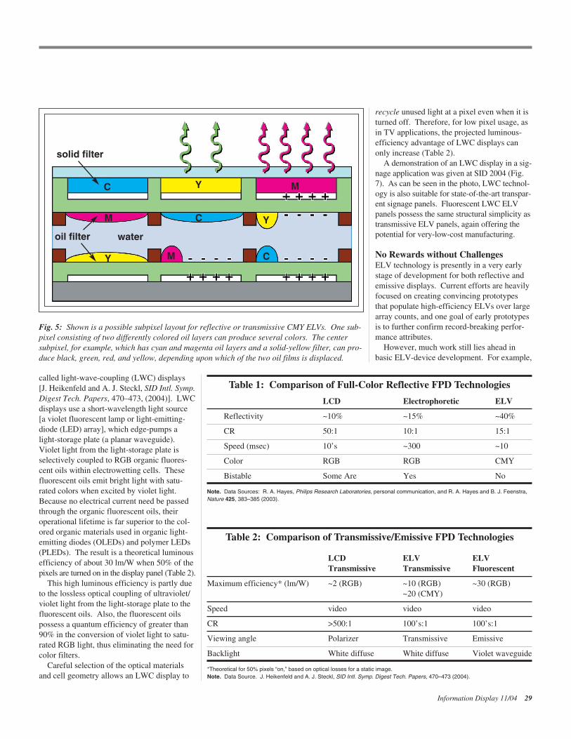
A high-brightness full-color reflective dis-play can be achieved by sandwiching a com-mon water layer between the YMC- andMCY-subpixel ELV arrays and attaching aCYM front color-filter array (Fig. 5). Forexample, one of the three colored subpixelscan consist of cyan and magenta oil layers anda solid-yellow filter (Fig. 5, center). This sub-pixel can then generate black, green, red, andyellow color based on which of the two oilfilms is displaced.
This reflective-CMY-ELV-display approachdeveloped by Philips has more than doublethe reflectivity of conventional reflective-display technologies based on liquid-crystal orelectrophoretic switching (Table 1). The dou-bling of reflectivity results from the fact thateach of the three colored subpixels comprisinga CMY ELV pixel can fully reflect two-thirdsof the visible spectrum (for example, yellow isred plus green). Furthermore, two of the threesubpixels can both generate saturated red,green, or blue (RGB) reflection. Other reflec-tive-display technologies that use RGB filter-ing can, at most, reflect only one-third of thevisible spectrum at each subpixel and can, atmost, provide saturated RGB color at only oneout of three subpixels.
Philips has already achieved a 40% reflec-tivity for full-color cells, with room forimprovement to the theoretical limit of justabove 60%. It is important to note that thebenefit of CMY filtering is only applicable todisplay technologies in which the light trans-missivity of the filter medium can be exter-nally switched. Therefore, at this time, only
Information Display 11/04 27
hydrophilicgrid
thinelectrode
hydrophobicinsulator
water water
waterwater
oil
oil
oil
oil
2D
0 V–+
10 V–
+
10 V–
+0 V–
+
3D
substrate
Fig. 2: A generic ELV device structure and its basic operation for displays is shown in 3-D(top) and 2-D (bottom) views. Typical oil volume for a 100 × 100-µm cell is only a few tenths ofa nanoliter.
Oil
Are
a / C
ell A
rea
(%) 1 × 3 mm Cell
100
90
0 –5 –10 –15 –20 –25
80
70
60
50
40
30
Voltage (V)
Fig. 3: A typical ELV voltage response isshown. Smaller-sized ELVs can modulate theoil area to as little as 10%. Less than 10-VELV operation has also been demonstrated.

ELVs can benefit from the high brightness ofthe CMY-filtering approach.
Because of their high brightness and simpledevice structure, reflective ELV displays are astrong candidate for electronic-paper applica-tions. Furthermore, the absence of a cell-gapdependence on reflectance permits a straight-forward extension of reflective ELV displaysto flexible/rollable-display formats. ELVs arenot yet suitable for “zero-power” displays
because reflective ELV displays are currentlynot bistable. However, ELVs have a switch-ing capacitance similar to that of LCD cells,which permits a very low power consumptionwell-suited to video-rate reflective displays incellular telephones, PDAs, and other portable-display applications.
In terms of display cost, the simplicity ofthe ELV-device structure should permitreflective ELV displays to be manufactured
at a cost comparable to or lower than that ofother reflective displays.
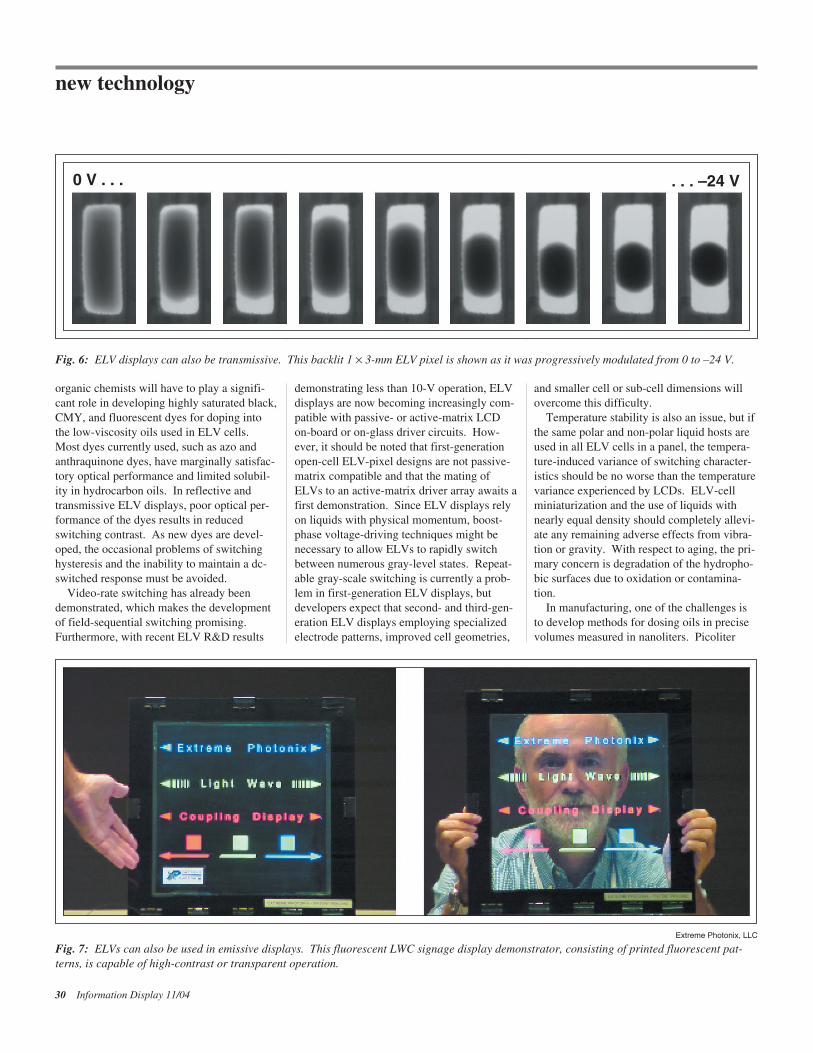
Emissive ELV DisplaysFollowing the pioneering reflective-ELV-display work at Philips, Extreme Photonix isdeveloping ELVs for emissive displays. Thecompany is now pursuing both color-filteredtransmissive and fluorescent emissive ELVdisplays. The nearly perfect light utilizationof reflective ELV displays is also characteris-tic of emissive ELV devices. The simplestextension of the generic ELV device shown inFig. 2 to transmissive displays requires that ablack oil be used in conjunction with a dif-fused-white-light backlight located behind aglass substrate. As the black oil is displacedwith increasing voltage, light transmittancethrough the ELV cell is increased to morethan 70% (Fig. 6). A standard RGB color-filter plate added to the front of a black-oilELV array creates the basis for a full-color-display panel.
Extreme Photonix has implemented severalother proprietary optical-enhancement tech-niques that cumulatively lead to a projectedpanel luminous efficiency of about 10 lm/W,assuming an 80-lm/W backlight with 50% ofthe pixels on. Use of the previously men-tioned CMY-filtering approach with twostacked ELV arrays doubles the average lumi-nous efficiency to about 20 lm/W. This lumi-nous efficiency is an order of magnitudegreater than the efficiencies achievable fortransmissive LCDs. An additional benefit isthat, unlike an LCD, a transmissive-ELV-display panel is inherently viewable at allangles without variation in image quality.
A transmissive-ELV-display panel shouldhave considerable cost advantages over LCDsbecause it (1) has no cell-gap dependence,permitting the use of low-cost color-filterarrays; (2) requires no additional films or materials for enhancing viewing angle; and(3) is so efficient that it can use lower-costand higher-efficiency edge-lit backlights.These potential cost advantages for transmis-sive ELV displays could be extremely pro-nounced in high-definition-television (HDTV)applications in which backlight and color-filter-array costs account for approximatelyone-half of the panel’s components and materials cost.
ELVs have also been implemented as aswitching mechanism in a novel emissive display developed at Extreme Photonix
28 Information Display 11/04
new technology
Philips Research Laboratories
Fig. 4: A reflective ELV 10 × 30 magenta array of 240 × 80-µm pixels biased at 0 V (a) and–15 V (b), and cyan (c) and yellow (d) arrays at 0 V.
(a) 0V (c) 0 V (d) 0 V
(b) –15V
called light-wave-coupling (LWC) displays [J. Heikenfeld and A. J. Steckl, SID Intl. Symp. Digest Tech. Papers, 470–473, (2004)]. LWCdisplays use a short-wavelength light source[a violet fluorescent lamp or light-emitting-diode (LED) array], which edge-pumps a light-storage plate (a planar waveguide). Violet light from the light-storage plate isselectively coupled to RGB organic fluores-cent oils within electrowetting cells. Thesefluorescent oils emit bright light with satu-rated colors when excited by violet light. Because no electrical current need be passedthrough the organic fluorescent oils, theiroperational lifetime is far superior to the col-ored organic materials used in organic light-emitting diodes (OLEDs) and polymer LEDs(PLEDs). The result is a theoretical luminousefficiency of about 30 lm/W when 50% of thepixels are turned on in the display panel (Table 2).
This high luminous efficiency is partly dueto the lossless optical coupling of ultraviolet/violet light from the light-storage plate to thefluorescent oils. Also, the fluorescent oilspossess a quantum efficiency of greater than90% in the conversion of violet light to satu-rated RGB light, thus eliminating the need forcolor filters.
Careful selection of the optical materialsand cell geometry allows an LWC display to
recycle unused light at a pixel even when it isturned off. Therefore, for low pixel usage, asin TV applications, the projected luminous-efficiency advantage of LWC displays canonly increase (Table 2).
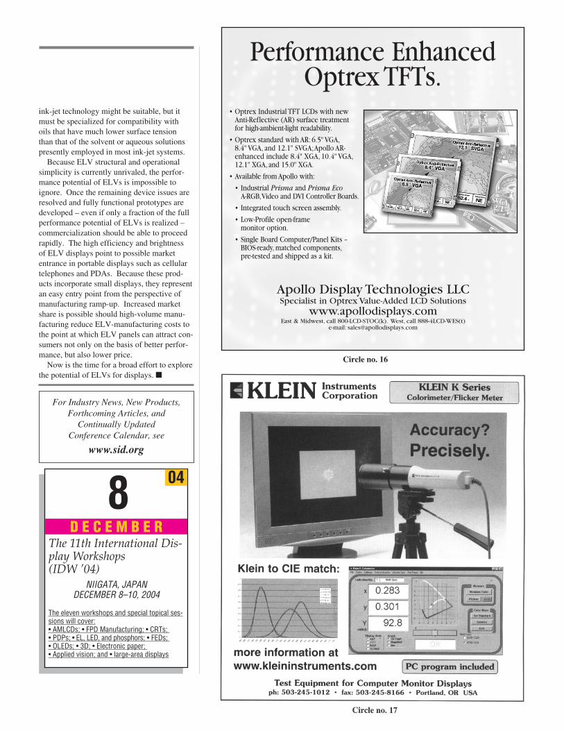
A demonstration of an LWC display in a sig-nage application was given at SID 2004 (Fig.7). As can be seen in the photo, LWC technol-ogy is also suitable for state-of-the-art transpar-ent signage panels. Fluorescent LWC ELVpanels possess the same structural simplicity astransmissive ELV panels, again offering thepotential for very-low-cost manufacturing.
No Rewards without ChallengesELV technology is presently in a very earlystage of development for both reflective andemissive displays. Current efforts are heavilyfocused on creating convincing prototypesthat populate high-efficiency ELVs over largearray counts, and one goal of early prototypesis to further confirm record-breaking perfor-mance attributes.
However, much work still lies ahead inbasic ELV-device development. For example,
Information Display 11/04 29
solid filter
water
M
M
C
C
C
Y
MY
Y
oil filter
Fig. 5: Shown is a possible subpixel layout for reflective or transmissive CMY ELVs. One sub-pixel consisting of two differently colored oil layers can produce several colors. The centersubpixel, for example, which has cyan and magenta oil layers and a solid-yellow filter, can pro-duce black, green, red, and yellow, depending upon which of the two oil films is displaced.
Table 1: Comparison of Full-Color Reflective FPD Technologies
LCD Electrophoretic ELV
Reflectivity ~10% ~15% ~40%
CR 50:1 10:1 15:1
Speed (msec) 10’s ~300 ~10
Color RGB RGB CMY
Bistable Some Are Yes No
Note. Data Sources: R. A. Hayes, Philips Research Laboratories, personal communication, and R. A. Hayes and B. J. Feenstra,Nature 425, 383–385 (2003).
Table 2: Comparison of Transmissive/Emissive FPD Technologies
LCD ELV ELVTransmissive Transmissive Fluorescent
Maximum efficiency* (lm/W) ~2 (RGB) ~10 (RGB) ~30 (RGB)~20 (CMY)
Speed video video video
CR >500:1 100’s:1 100’s:1
Viewing angle Polarizer Transmissive Emissive
Backlight White diffuse White diffuse Violet waveguide
*Theoretical for 50% pixels “on,” based on optical losses for a static image.Note. Data Source. J. Heikenfeld and A. J. Steckl, SID Intl. Symp. Digest Tech. Papers, 470–473 (2004).
organic chemists will have to play a signifi-cant role in developing highly saturated black,CMY, and fluorescent dyes for doping intothe low-viscosity oils used in ELV cells.Most dyes currently used, such as azo andanthraquinone dyes, have marginally satisfac-tory optical performance and limited solubil-ity in hydrocarbon oils. In reflective andtransmissive ELV displays, poor optical per-formance of the dyes results in reducedswitching contrast. As new dyes are devel-oped, the occasional problems of switchinghysteresis and the inability to maintain a dc-switched response must be avoided.
Video-rate switching has already beendemonstrated, which makes the developmentof field-sequential switching promising. Furthermore, with recent ELV R&D results
demonstrating less than 10-V operation, ELVdisplays are now becoming increasingly com-patible with passive- or active-matrix LCDon-board or on-glass driver circuits. How-ever, it should be noted that first-generationopen-cell ELV-pixel designs are not passive-matrix compatible and that the mating ofELVs to an active-matrix driver array awaits afirst demonstration. Since ELV displays relyon liquids with physical momentum, boost-phase voltage-driving techniques might benecessary to allow ELVs to rapidly switchbetween numerous gray-level states. Repeat-able gray-scale switching is currently a prob-lem in first-generation ELV displays, butdevelopers expect that second- and third-gen-eration ELV displays employing specializedelectrode patterns, improved cell geometries,
and smaller cell or sub-cell dimensions willovercome this difficulty.
Temperature stability is also an issue, but ifthe same polar and non-polar liquid hosts areused in all ELV cells in a panel, the tempera-ture-induced variance of switching character-istics should be no worse than the temperaturevariance experienced by LCDs. ELV-cellminiaturization and the use of liquids withnearly equal density should completely allevi-ate any remaining adverse effects from vibra-tion or gravity. With respect to aging, the pri-mary concern is degradation of the hydropho-bic surfaces due to oxidation or contamina-tion.
In manufacturing, one of the challenges isto develop methods for dosing oils in precisevolumes measured in nanoliters. Picoliter
30 Information Display 11/04
new technology
Fig. 6: ELV displays can also be transmissive. This backlit 1 × 3-mm ELV pixel is shown as it was progressively modulated from 0 to –24 V.
0 V . . . . . . –24 V
Extreme Photonix, LLC
Fig. 7: ELVs can also be used in emissive displays. This fluorescent LWC signage display demonstrator, consisting of printed fluorescent pat-terns, is capable of high-contrast or transparent operation.
ink-jet technology might be suitable, but itmust be specialized for compatibility with oils that have much lower surface tension than that of the solvent or aqueous solutionspresently employed in most ink-jet systems.
Because ELV structural and operationalsimplicity is currently unrivaled, the perfor-mance potential of ELVs is impossible toignore. Once the remaining device issues areresolved and fully functional prototypes aredeveloped – even if only a fraction of the fullperformance potential of ELVs is realized – commercialization should be able to proceedrapidly. The high efficiency and brightness of ELV displays point to possible marketentrance in portable displays such as cellulartelephones and PDAs. Because these prod-ucts incorporate small displays, they representan easy entry point from the perspective ofmanufacturing ramp-up. Increased marketshare is possible should high-volume manu-facturing reduce ELV-manufacturing costs tothe point at which ELV panels can attract con-sumers not only on the basis of better perfor-mance, but also lower price.
Now is the time for a broad effort to explorethe potential of ELVs for displays. �
Information Display 11/04 31
For Industry News, New Products, Forthcoming Articles, and
Continually Updated Conference Calendar, see
www.sid.org
048D E C E M B E R
The 11th International Dis-play Workshops (IDW ’04)
NIIGATA, JAPANDECEMBER 8–10, 2004
The eleven workshops and special topical ses-sions will cover:• AMLCDs; • FPD Manufacturing; • CRTs; • PDPs; • EL, LED, and phosphors; • FEDs; • OLEDs; • 3D; • Electronic paper; • Applied vision; and • large-area displays
• Optrex Industrial TFT LCDs with newAnti-Reflective (AR) surface treatment for high-ambient-light readability.
• Optrex standard with AR: 6.5" VGA,8.4" VGA, and 12.1" SVGA;Apollo AR-enhanced include 8.4" XGA, 10.4" VGA,12.1" XGA, and 15.0" XGA.
• Available from Apollo with:
• Industrial Prisma and Prisma EcoA-RGB,Video and DVI Controller Boards.
• Integrated touch screen assembly.
• Low-Profile open-frame monitor option.
• Single Board Computer/Panel Kits – BIOS-ready, matched components,pre-tested and shipped as a kit.
Performance EnhancedOptrex TFTs.
Apollo Display Technologies LLCSpecialist in Optrex Value-Added LCD Solutions
www.apollodisplays.comEast & Midwest, call 800-LCD-STOC(k). West, call 888-4LCD-WES(t)
e-mail: [email protected]
Circle no. 16