ICP-1153 Distributed Under Category: UC-66d GE Uti Techno1 ogy
43
ICP-1153 Distributed Under Category: GE : Uti 1 i za ti on Techno1 ogy UC-66d Liquid- F1 ui di zed-Bed Heat Exchanger Design Parameters C. A. Allen E. S. Grimmett Allied Chemical Corporation Idaho Chemi,cal Programs - Operations Office Date Published - April 1978 ' Prepared for the Department of Energy Idaho Operations Office Under Contract I-(322)-1570
Transcript of ICP-1153 Distributed Under Category: UC-66d GE Uti Techno1 ogy
ICP-1153 Distributed Under Category:
GE : U t i 1 i za ti on Techno1 ogy UC-66d
Liquid- F1 u i d i zed-Bed Heat Exchanger Design Parameters
C. A. Allen E. S. Grimmett
Allied Chemical Corporation Idaho Chemi,cal Programs - Operations Office
Date Published - April 1978
' Prepared for the Department of Energy
Idaho Operations Office Under Contract I-(322)-1570
DISCLAIMER
This report was prepared as an account of work sponsored by an agency of the United States Government. Neither the United States Government nor any agency Thereof, nor any of their employees, makes any warranty, express or implied, or assumes any legal liability or responsibility for the accuracy, completeness, or usefulness of any information, apparatus, product, or process disclosed, or represents that its use would not infringe privately owned rights. Reference herein to any specific commercial product, process, or service by trade name, trademark, manufacturer, or otherwise does not necessarily constitute or imply its endorsement, recommendation, or favoring by the United States Government or any agency thereof. The views and opinions of authors expressed herein do not necessarily state or reflect those of the United States Government or any agency thereof.

DISCLAIMER Portions of this document may be illegible in electronic image products. Images are produced from the best available original document.

Abstract
liquid-flujdized-bed heat exchangers prevent scale accumulation on heat transfer surfaces and reduce the required heat transfer surface when scaling fluids such as geothermal water are used as the primary or working fluid. exchangers, principles of operation and design parameters. Horizontal and vertical assemblies are discussed, fncluding problems encountered w i t h both designs. Bed-side heat transfer coefficients are given for I i m i ted cases, and a correlation i s provided for calculating heat transfer coefficients for horizontal assemblies. A design example for a 60 kw(e) (60 kn(e1ectri.c) preheater i s included.
T h i s report describes liquid-fluidized-bed heat
i i
Summary
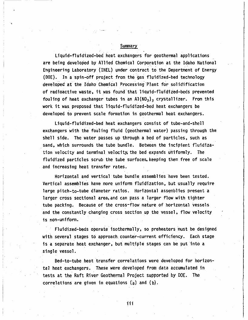
L iqu id- f lu id ized-bed heat exchangers for geothermal appl icat ions are being developed by A l l i e d Chemical Corporation a t the Idaho National Engineering Laboratory (INEL) under contract t o the Department o f Energy (DOE). I n a s p i n - o f f p ro jec t from the gas fluidized-bed technology developed a t the Idaho Chemical Processing Plant for s o l i d i f i c a t i o n o f rad ioac t ive waste, i t was found t h a t l iqu id- f lu id ized-beds prevented fou l ing o f heat exchanger tubes i n an A1(N03)3 c r y s t a l l i z e r . From t h i s work i t was proposed t h a t l iqu id - f lu id ized-bed heat exchangers be developed t o prevent scale formation i n geothermal heat exchangers.
L iqu id - f 1 u i d i zed-bed heat exchangers consis t o f tube-and-she1 1 exchangers w i t h the f o u l i n g f l u i d (geothermal water) passing through the she l l side. The water passes up through a bed o f pa r t i c l es , such as sand, which surrounds the tube bundle. t i o n v e l o c i t y and terminal velocity, the bed expands formly. The f l u i d i z e d p a r t i c l e s scrub the tube surfaces, keeping them f ree o f scale and increasing heat t rans fe r rates.
Between the i n c i p i e n t f l u i d i z a -
Hor izontal and v e r t i c a l tube bundle assemblies have been tested. Ve r t i ca l assemblies have more ,uni form f l u i d i z a t i o n , but usua l ly requ i re l a rge p i tch-to-tube diameter r a t i o s . l a r g e r cross sect ional area,and can pass a l a r g e r f low w i t h t i g h t e r tube packing. and the constant ly changing cross sect ion up the vessel, f low v e l o c i t y i s non-uniform.
Hor izontal assemblies present a
Because o f the cross-f low nature o f hor izonta l vessels
Fluidized-beds operate isothermal ly, so preheaters must be designed w i t h several stages t o approach counter-current e f f i c i ency . i s a separate heat exchanger, bu t m u l t i p l e stages can be pu t i n t o a s ing le vessel.
Each stage
Bed-to-tube heat t rans fe r cor re la t ions were developed f o r horizon- t a l heat exchangers. These were developed from data accumulated i n t e s t s a t the Raf t River Geothermal Pro ject supported by DOE. The cor re la t ions are given i n equations (a) and (b),
iii
where .4 < E < .76
where .76 5 E < 1.0
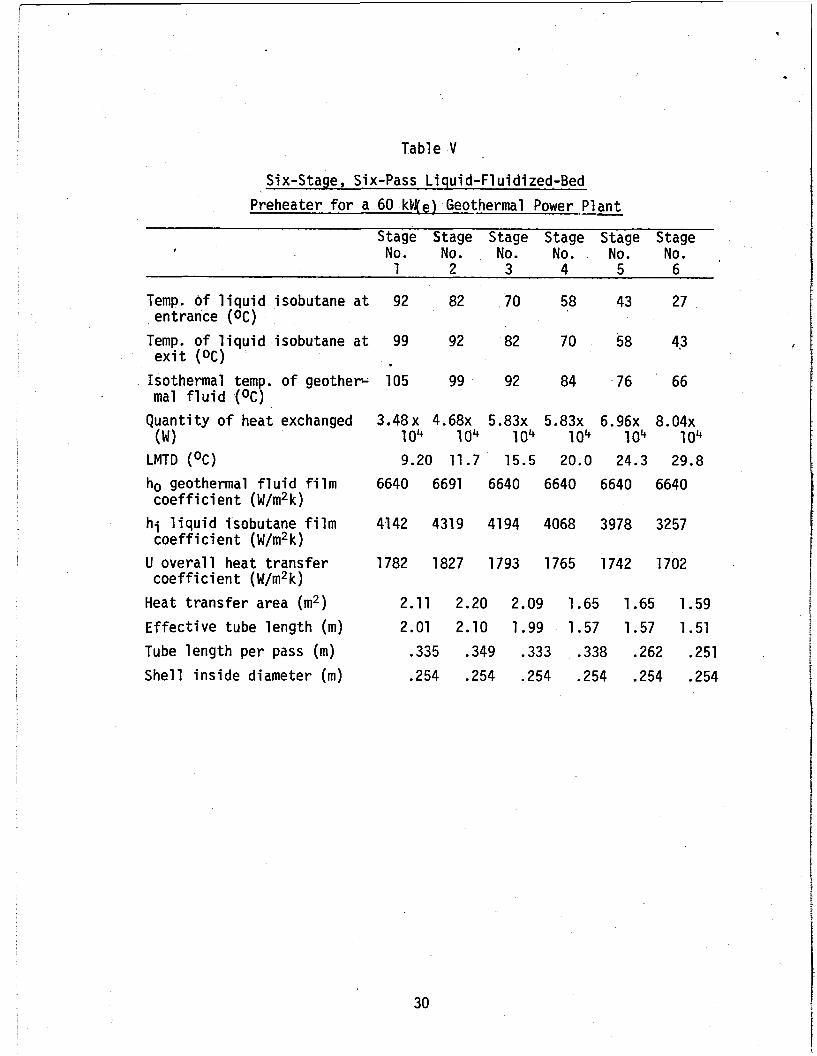
Using the design constraints described i n the report, a design example i s given for a 60 kW(e) six-stage preheater. Impact of the constraints becomes clearer when applied to a real heat exchanger.
!
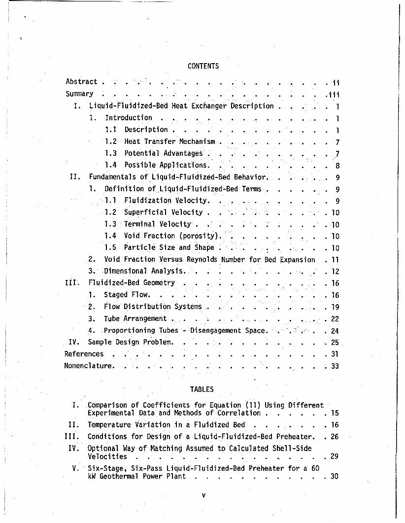
CONTENTS
Abstract . . . . . . . . . . . . . . . . . . Sumnary . . . . . . . . . . . . . . . . .
I . Liquid-Fluidized-Bed Heat Exchanger Description . . . . . . . . . . . . . . 1 . Introduction
1.1 Description . . . . . . . . . . . 1.2 Heat Transfer Mechanism . . . . . . . 1.3 Potential Advantages . . . . . . . . 1.4 Possible Applications . . . . . . . . .
I1 . Fundamentals of Liquid-Fluidized-Bed Behavior . . . 1 . Definition of Liquid-Fluidized-Bed Terms . . .
1.1 Fluidization Velocity . . . . . . . . 1 . 2 Superficial Velocity . . . . ' . . . . . 1.3 Terminal Velocity . . . . . . . . . 1.4 Void Fraction (porosity) . . . . . . . 1.5 Particle Size and Shape . . . . . . . .
. . . i i
. . . i i i
. . . 1
. . . 1
. . . 1
. . . 7
. . . 7
. . . 8
. . . 9
. . . 9
. . . 9
. . . 10
. . . 10
. . . 10
. . . 10 2 . Void Fraction Versus Reynolds Number for Bed Expansion . 1 1 3 . I Dimensional Analysis . . . . . . . . . . . . . 12
I11 . Fluidized-Bed Geometry . . . . . . . . . . . . 16
Flow Distribution Systems . . . . . . . . . . . 19 Tube Arrangement . . . . . . . . . . . . . . . 22 Proportioning Tubes . Disengagement Space . . . . . . . . . 24
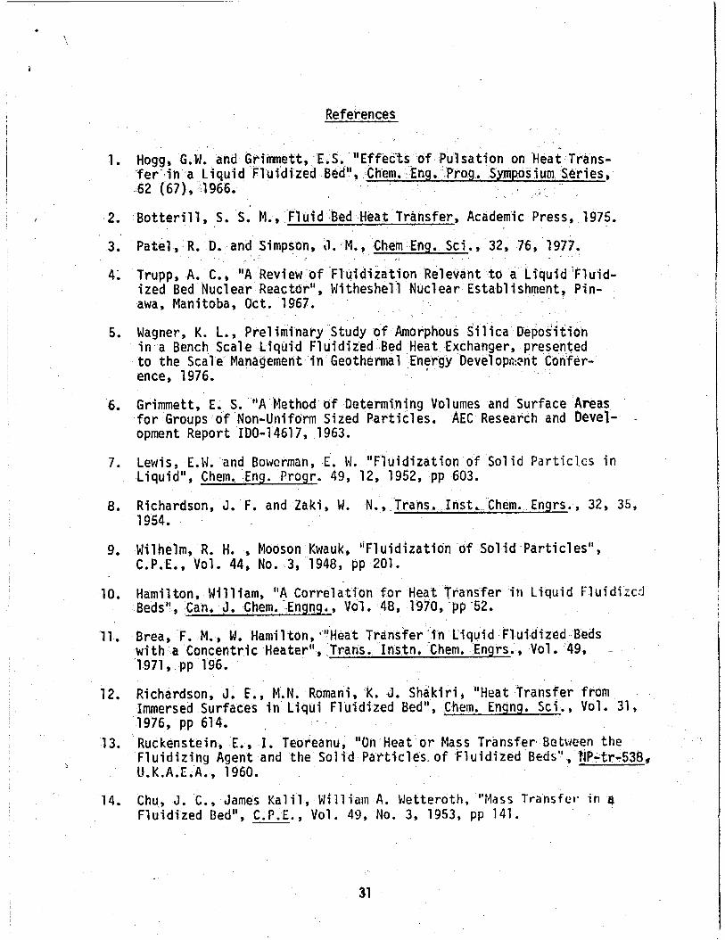
Sample Design Problem . . . . . . . . . . . . . . . 25 References . . . . . . . . . . . . . . . . . . . 31 Nomenclature . . . . . . . . . . . . . . . . . . . 33
. . . . . . . . . . . . . . . . 1 . Staged Flow 16 2 . 3 . 4 .
IV .
TABLES
I . Comparison o f Coefficients for Equation (11) Using Different Experimental Data and Methods of Correlation . . . . . . 15
I1 . Temperature Variation in a Fluidized Bed . . . . . . . 16 I11 . Conditions for Design of a Liquid-Fluidized-Bed Preheater . . 26 IV . Optional Way o f Matching Assumed t o Calculated Shell-Side
Velocities 29 V . Six-Stage, Six-Pass Liquid-Fluidized-Bed Preheater for a 60
kW Geothermal Power Plant . . . . . . . . . . . . 30 . . . . . . . . . . . . . . . . .
V
~
I
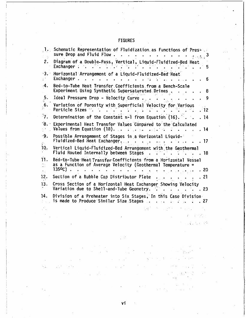
I FIGURES
l . , Schematic Representation of Fluidization as Functions of Pres; - 1 sure Drop and Fluid Flow . . . . . . . . . . . . . 3 I ,
2. Diagram of a Double-Pass, Vertical, Liquid-Fluidized-Bed Heat Exchanger . . . . . . . . . . . . . . . . . . . . . . 5 I .
3. Horizontal Arrangement of a Liquid-Fluidized-Bed" Heat . . Exchanger . . . . . . . . . . s i . . . . . . . 6 4. Bed-to-Tube Heat Transfer Coeffjcients. from a Bench-Scale
Experiment Using Synthetic Supersaturated Brines . . . . . 8 5. Ideal Pressure Drop - Velocity Curve . . . . . . . . . . 9 ,6. Variation of Porosity with Superficial Velocity for .Various . Particle Sizes . . . . . . . . . . . . . . . . . . . . 12 :7. Determination of the Constant n-1 flnom Equation'(l6). . . . . . 14 ' 8 . Experimental Heat Transfer Values 'Compared to the 'Calculated
Values from Equation (18). . . . . . . . . . . . . 14 9. Possible Arrangement of Stages in a -Horizontal Liquid-
Fluidized-Bed Heat Exchanger., . . . . . . . . . . . . 17 Vertical Liquid-Fluidized-Bed Arrangement with 'the Geothermal Fluid Routed Internally -between Stages . . . . . . . . . 18 as a Function o f Average Velocity (Geothermal Temperature = 135OC) . . . . . . . . . . . . . . . . . . . . . 20
Cross Section o f a Horizontal Heat Exchanger Showing Velocity
p r
3 -
io-.
11. Bed-to-Tube Heat Transfer Coefficients from a Horizontal Vessel
12. Section of a Bubble Cap Distributor Plate . . . . . . . 21 . Variation due to Shell-and-Tube Geometry. . . . . . . . 23 13.
14. Division of a Preheater into Six Stages,'In this Case Division is made to Produce Similar Size Stages . . . . . . . . 27
vi
I . Liquid-Fluidized-Bed Heat Exchanger Description
1. Introduction
1.1 Description
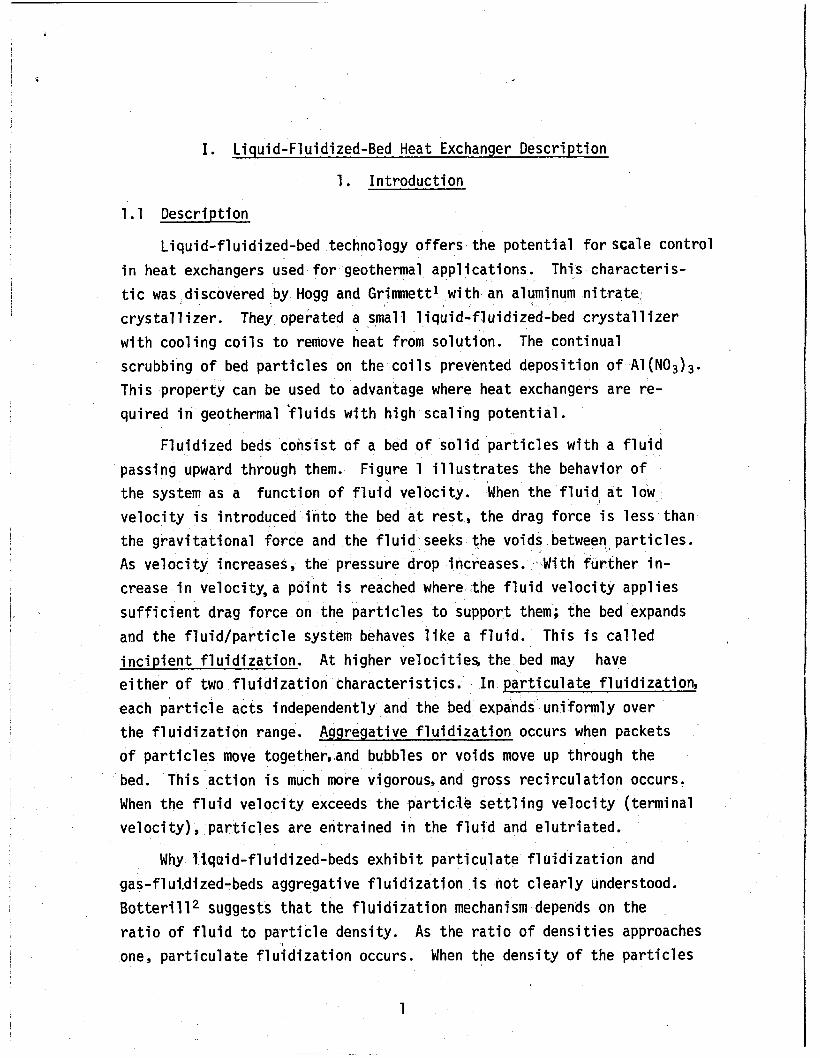
Liquid-fluidized-bed technology offers the potential for scale control i n heat exchangers used for geothermal applications. t i c was discovered by Hogg and Grimmett' w i t h an aluminum nitrate. crystall izer. They operated a small liquid-fluidized-bed crystall izer w i t h cooling coi ls to remove heat from solution. scrubbing of bed particles on the coils prevented deposition of A1 (N03)3. T h i s property can be used to advantage where heat exchangers are re- quired i n geothermal 'fluids w i t h h i g h scaling potential.
T h i s characteris-
The continual
Fluidized beds consist of a bed of solid particles w i t h a f luid passing upward through them. Figure 1 i l lustrates the behavior of the system as a function of f l u i d velocity. velocity is introduced into the bed a t rest, the drag force i s less than the gravitational force and the fluid seeks the voids between particles. As velocity increases, the pressure drop increases. - W i t h further i n - crease i n velocity,a point is reached where the f l u i d velocity applies sufficient drag force on the particles to support them; the bed expands and the fluid/particle system behaves l ike a f l u i d . incipient fluidization. A t higher velocities, the bed may have either of two f lu id iza t ion characteristics. each particle acts independently and the bed expands uniformly over the fluidization range. of particles move together,and bubbles or voids move up through the bed. When the f l u i d velocity exceeds the particle settling velocity (terminal velocity)
When the f l u i d a t low
T h i s is called
In particulate fluidization,
Aggregative fluidization occurs when packets
T h i s action i s much more vigorous, and gross recirculation occurs.
particles are entrained i n the fluid and elutriated.
Why liquid-fluidized-beds e x h i b i t particulate fluidization and gas-f 1 ui.di zed- beds aggregati ve f 1 u i d i zati on i s not cl early understood . Botterill* suggests t h a t the fluidization mechanism depends on the r a t i o of f luid t o particle density. As the ra t io of densities approaches one, particulate fluidization occurs. When the density of the particles
1

STYLIZED REPRESENTATION OF . .
RESPONSE OF BED TO UPWARDS OF FLUID THROUGH IT
8 ID m Y)
u c 0 QI 0 w re 3 rn
n
z LlQUlO LlQUlO 6AS
L - I
FLUID FLOW RATE WEL-S-2036
Figure 1. Schematic Representation o f F lu id izat ion as Function: of F lu id Flow Rate=&uidizi .n~ Rrf,g is e i t h e r l i q u i d or aas. as. shbwn. e r B$t r
2

I
I ? I ~
~
! !
b
i s much greater than the f l u i d density, aggregative f l u i d i z a t i o n resul ts . I n general, l iqu id- f lu id ized-beds e x h i b i t p a r t i c u l a t e f l u i d i z a t i o n and gas-f 1 uidized-beds aggregative f i u i d i zation. The densi ty re1 at ionship
was supported by Pate1 and Simpson,3 who found aggregative f l u i d i z a t i o n i n beds o f lead shot f l u i d i z e d w i t h water and p a r t i c u l a t e f l u i d i z a t i o n w i t h beds o f glass beads f l u i d i z e d w i t h water.
Gas-fluidized-bed technology i s we1 1 devel oped and has been used
extensively for p a r t i c l e coating, ca lc inat ion, and drying. However, 1 iqu id- f lu id izedibed technology remains r e l a t i v e l y undeveloped. The l a r g e s t body of l i t e r a t u r e i s the r e s u l t o f the f e a s i b i l i t y study o f a l iqu id- f lu id ized-bed nuclear reactor. This deals w i t h heat t ransfer from pa r t i c l es , which contain fuel, t o the l i q u i d , which acts as a coolant and moderator. Asummary o f t h i s work through 1966 i s published by A. C. Trupp.
l iqu id- f lu id ized-bed heat exchangers are made by immersing a tube bundle o r c o i l i n the bed. I n t h i s case, the geothermal f l u i d i s on the s h e l l s ide of the exchanger and the secondary f l u i d on the tube side. This reverses the normal design of the geothermal heat exchangers where the geothermal water passes throughthe tubes t o f a c i l i t a t e scale removal. There are two advantages t o p u t t i n g the geothermal f l u i d on the s h e l l side.
J 1. Organic secondary f l u i d t ransfer heat a t a lower r a t e than water. Pu t t i ng them through the tubes a t h igh v e l o c i t y subs tan t i a l l y increases the ove ra l l heat t rans fe r ra te.
f l u i d . This reduces the design requirement on s h e l l thickness and lowers the cost.
2. Geothermal b r i ne i s usua l l y a t lower pressure than the secondary
3
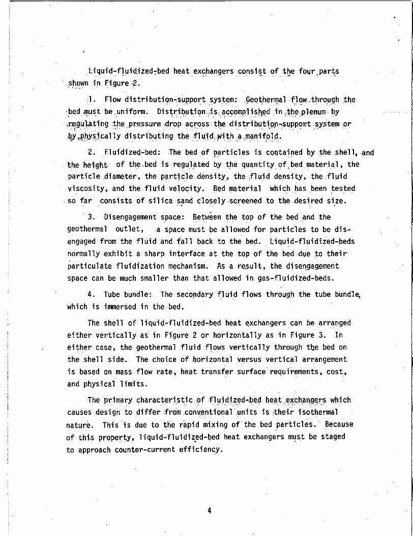
Liquid-fluidizedTbed heat exc.hangers consist of the c foqr<parts shown in Figure -2. I "
1. Flow distri bution-support . .. system: .Geot.herql f1o.w .through the ,bed must \ . be.uniform. Dist
e pressure dr $hysically distributing the fluid with a .manifold. 3 .
2. Fluidized-bed: The bed of particles * I is contained by the shell, and the height of the.bed is regulated by the quantity of .bed.material , the particle diameter, the particle density, the fluid density, the fluid viscosity, and the fluid velocity. Bed material so far consists of silica '. sand closely.screened to the desired size.
3.
which has been tested L .
Disengagement space: Between the top of the bed and the geothermal outlet, engaged from the fluid and fall back to the bed. normally exhibit a sharp interface at the top of the bed due to their particulate fluidization mechanism. As a re,sul t, the disengagement space can be much smaller than that allowed in gas-fluidized-beds.
a space must be allowed for particles to be dis- Liquid-fluidized-beds
4. Tube bundle: The secondary fluid flows through the tube bundle, which is immersed in the bed.
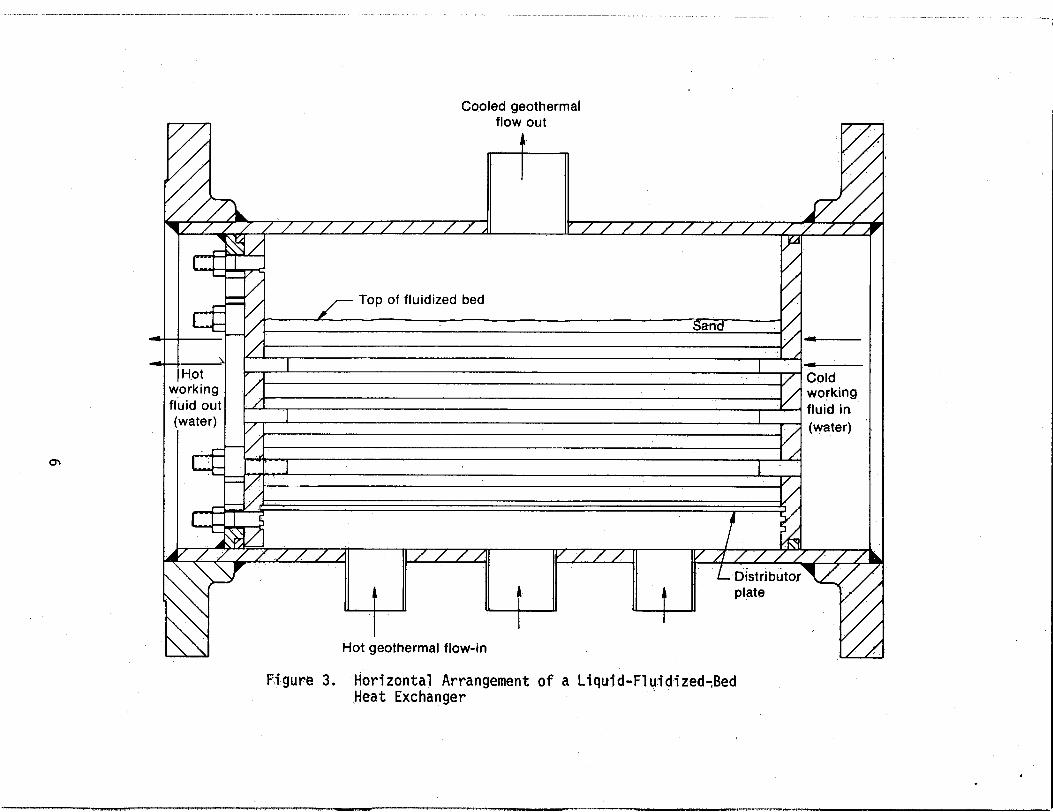
The shell of liquid-fluidized-bed heat exchangers can be arranged either vertically as in Figure 2 or horizontally as .in Figure 3. either case, the geothermal fluid flows vertically through the bed on the shell side. The choice of horizontal versus vertical arrangement is based on mass flow rate, heat transfer surface requirements, cost, and physical 1 imi ts.
In
The primary charac causes design to differ from .conventional units is their isothermal nature. This is due to the rapid mi.xing of the bed particles. of this property, 1 iquid-fluidized-bed heat exchangers must be staged to approach counter-current efficiency.
Because
4

Secondary Secondary fluid in fluid out
- Distributor plate
i
'
Geothermal ,fluid in
Figure 2. Diagram o f a Double-Pass, Vertical, Liquid-Fluidized-Bed Heat Exchanger
5
f l f l Cooled geothermal
flow out c
- Top of fluidized bed Y
Sand - - Norking
(water) I
1
E-;' fluid out
~ /
,' , ; (water)
4- 4 - - -
/
Figure 3. Horizontal Arrangement o f a Liquid-FluidizedtBed Heat Exchanger
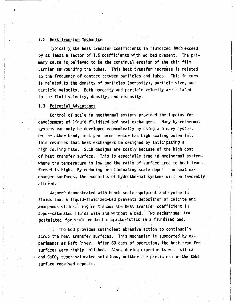
1.2 Heat Transfer Mechanism
Typical 1% the heat transfer coefficients i n fluidized beds exceed by a t least a factor of 1.5 coeffidients w i t h no bed present. The pri- mary cause is believed t o be the continual erosion of the t h i n film barrier surrounding the tubes. t o the frequency of contact between particles and tubes. is related t o the density o f particles (porosity), particle size, and particle velocity. Both porosity and particle velocity are related
T h i s heat transfer increase is related This in t u r n
to the f l u i d velocity, density, and viscosity.
1.3 Potential Advantages ,
Control 'of scale i n geothermal systems provided the impetus for development of liquid-fluidized-bed heat exchangers. Many hydrothermal systems can only be developed economically by using a binary system.
/
On the other hand, most geothermal water has h i g h scaling potential. T h i s requires t h a t heat exchangers be designed by anticipating a h i g h fou l ing rate. Such designs are costly because of the high cost of heat transfer surface. where the temperature i s low and the r a t i o of surface area t o heat trans- ferred is h igh . By reducing or eliminating scale deposit on heat ex- changer surfaces, the economics of hydrothermal systems will be favorably a1 tered.
T h i s is especially true i n geothermal systems
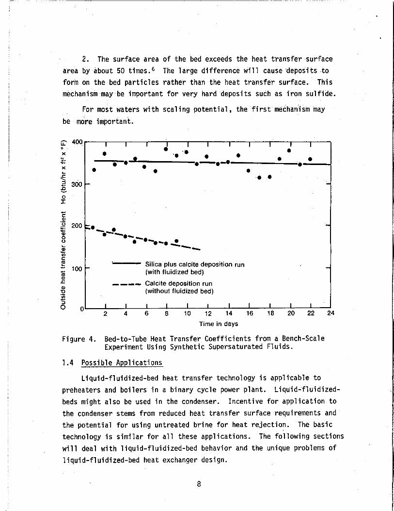
Wagner5 demonstrated w i t h bench-scale equipment and synthetic f l u i d s t h a t a liquid-fluidized-bed prevents deposition of calcite and amorphous s i l i ca . Figure 4 shows the heat transfer coefficient i n super-saturated fluids w i t h and wi thout a bed. Two mechanisms are postulated for scale control character ts t ics#in.a fluidized bed.
1. The bed provides sufficient abrasive action to continually scrub the heat transfer surfaces. This mechanism is supported by ex- periments a t Raft River. After 60 days of operation, the heat transfer surfaces were highly polished. Also, dur ing experiments with s i l i ca and CaCO, super-saturated solutions, neither the particles nor the 'tube surface. received deposit.
~
2. The surface area o f the bed exceeds the heat transfer surface area by about 50 times.6 The large difference will cause deposits t o form on the bed particles rather than the heat transfer surface. This mechanism may be important for very hard deposits such as iron sulfide.
For most waters with scaling potential, the first mechanism may be more important.
400 0
X N c c
X L
f 2 300 b, 0 I
I I I I I I I I I I I 0
0 0 0 0 0 .. ' 0 - .-.a 0-
0 0 . 0 0 0 .. .
Silica plus calcite deposition run (with fluidized bed) - --- Calcite deposition run (without f I uid ized bed)
'-
I I I I I I I I I I I 2 4 6 8 10 12 14 16 18 20 22 24
Time in days
Figure 4. Bed-to-Tube Heat Transfer Coefficients from a Bench-Scale Experiment Using Synthetic Supersaturated Fluids.
1.4 Possible Applications
Liquid-fl uidized-bed heat transfer technology i s applicable t o preheaters and boilers i n a binary cycle power plant. beds might also be used i n the condenser. Incentive fo r application t o the condenser stems from reduced heat transfer surface requirements and the potential for using untreated brine for heat rejection. technology is similar for a l l these applications. The following sections will deal with liquid-fluidized-bed behavior and the unique problems of liquid-fluidized-bed heat exchanger design.
Liquid-fluidized-
The basic
8
11. Fundamentals of Liquid-Fluidized-Bed Behavior
1. Definitions of Liquid-Fluidized-Bed Terms
1.1 Flu id iza t ion Velocity
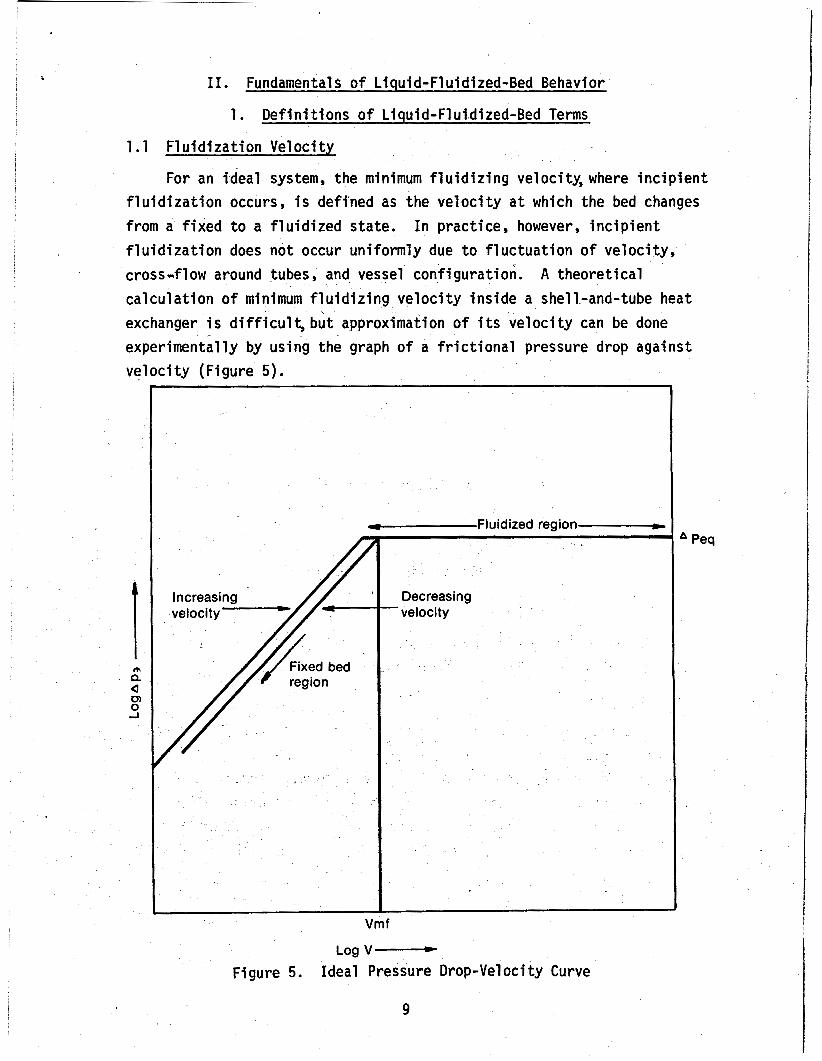
For an ideal system, the minimum fluidizing velocity, where incipient fluidization occurs, i s defined as the velocity a t which the bed changes from a fixed t o a f lu id i zed state. f l u i d i z a t i o n does not occur uniformly due t o fluctuation of velocity, cross-flow around tubes, and vessel configuration. calculation of minimum fluidizing velocity inside a shell-and-tube heat exchanger i s difficult , b u t approximation of i t s velocity can be done experimentally by us ing the graph of a frictional pressure drop against velocity (Figure 5).
In practice, however, incipient
A theoretical
Fluidized region-
1
Decreasing velocity -
f
Log v-
Peq
Figure 5. Ideal Pressure Drop-Vel oci ty Curve
1.2 Superficial Velocity
Superficial velocity is the vertical component of f l u i d velocity th rough the shel l , assuming the shell contains only fluid.
- 1 dM vo - -- F f k d t
1 . 3 Terminal Velocity
Terminal velocity is defined as a velocity of a solid particle fall ing freely from res t i n a stationary fluid under the action of gravity. derived as follows:
The terminal velocity ( v t ) for a sand particle can be
The drag
ad
force around a sphere of diameter (dp) is defined by :
(2) Fk = (% p j v t 2 ) Dc
T h i s force is balanced by the gravitational force minus Bhe bouyancy force on the sphere.
Fk = 1/6 rdp39c(ps - P f )
Equating ( 2 ) and (3 ) then solving for v t gives: 4 dp ( P s - P f ) v t 2 = 3
P f ( 4 )
Where the drag coefficient (Dc) w i t h a sphericity factor of 0.806 (sand) and h i g h Reynolds number i s found to be about 1.6.
1.4 Void Fraction
Void fraction (porosity = E ) i s a measure of interparticle space Volume of Sand Total Volume and i s expressed as: E = 1 -
Yoad fraction a t res t depends on the surface texture, sphericity, uniformity of the grain size, and c6mentation or compaction of the sand. sedimentation.
Expressed as a void fraction, the normal value i s about0.42% af te r Void fraction depends on velocity i n a fluidized system.
1.5 Particle Size and ShaDe
The particle size as used here i s a mean particle diameter (MPD) w i t h standard deviation of about - +30%. Particle shape is expressed by the sphericity factor,which i s -defined as the rat io of surface area of
10
a sphere having the same volume as the particle t o surface area of the particle. For sand, the sphericity i s found t o be 0.806.
2. Void Fraction Versus Reynold Number Relationships for Bed Expansion
Liquid-fluidized-beds e x h i b i t the characteristic of a stream1 ine l i q u i d . The bed expands smoothly as velocity is increased from the incipient fluidizing velocity to terminal velocity, assuming uniform particulate fluidization. As the l i q u i d velocity increases, the height of the bed increases, and particle concentration decreases until eventually particles become entrained i n the l i q u i d and escape from the bed. The free sett l ing velocity of a particle is no t directly applicable to suspensions of large numbers of particles, where neigh- boring particles interfere w i t h each other. Hence, the effect of the set t l ing velocity is reduced. i n the form of the porosity ( E ) and superficial veTocity (vo) .
T h i s reduction r a t i o may be expressed
vo = v t d (5)
Lewis, (et.al . ) 7 proposed the empirical relation, equation (6), fo r uniform size catalyst particles fluidized ' i n l i qu ids .
VO = 0.72 v t c 2 * 3 3 for Re = PfVodP > 500 (6) w Richardson and Zaki conducted extensive experiments and established
empirical correlations for the exponent ' m ' as a function of Re and
where log v i = log v t - dp/Dt
m = 4.45 R e - O o 1
(8)
(9) m = 4.45 + 18(dp/Dt) Re-0.l
m = 2.39
for 1 < Re < 200 for 200 < Re < 500 for Re > 500
However, Richardson i n a more recent report shows this equation is un- reliable under conditions where uniform fluidization is no t obtained. In heat exchangers, the tube bundle makes uniform fluidization very d i f f icu l t t o achieve. T h i s leads t o increased dp/Dt dependence i n equation (5). Our proposed equation is:
11

where m = 8.85/log(dp), dp-is in microns and 1 Rep < 200
This relation was extrapolated from Wilhelm and Kwauk's9 work and our own data on sand fluidized with water, as shown in Figure 6.
I I 1 I I I 1 I I I I I I
3 000
2 000 - E E
N
2
a
- 0,
1000 al - c 2 O.?OO
I6,20
I Ooh 10 60 15 30 23 00
I 1 1 I 1 I I I I I I I . 2 4 8 3 4 0 3 9 3 4 9 3 6 2 2 7 8 0 9 8 6 1 2 4 0 1 5 6 0 1 9 7 0 2 4 8 0 3 1 2 0
Superficial velocity (ft/m)
Figure 6. Variation of Porosity with Superficial Velocity for Various Particle Sizes (ft/min = 5.08 x m/sec) T=135OC
3. Dimensional Analysis
A number of correlations have been proposed for calculating surface heat transfer coefficients for both vertical tubes and horizontal tubes in fluidized beds. been correlated empirically on the basis o f a limiting film and bed resistance at the heat transfer surface.
In general, the results of these experiments have
The most adequate papers on the studies of heat transfer in liquid fluidized-bed are those by: (et.al),12 Ruckensten and Toereanu,13 Chu (et.al .),14 and Wasmund and
HamiltonY1o Brea (et.al) ,I1 Richardson
Smith. l 5
All workers, except Ruckenstein and sional groups are arranged in the follow
Nu = a Retb Pre cd ( l - ~ ) ~ (2) f
12
Wasmund, agree that the dimen- ng general form:
(11)

The constant and exponents (a, b, c, d, e, f) are found experimen- t a l l y i n the fo l low ing way: Hamilton and Brea co r re la te t h e i r data
by Chu's Colburn J- factors where Richardson uses J a g n n a d j a r a j u ' ~ ' ~ Colburn J- factors. Our data f i t s Chu's J-factor. The J-factor i s defined as:
Nu . Reo pr1'3
J =
and Chu;s J - fac to r i s
J = C
where C i s a constant.
Super f i c ia l v e l o c i t y (VO) and terminal v e l o c i t y ( v t ) i n the i n t e r - mediate t o tu rbu len t f low region are re la ted by:
Ret = Reo ( E ) ~ (14) 8.85
l o g dp where m =
Subst i tu t ion o f (14) i n t o (12):
Nu = C P r 1 / 3 Retn-' @ (E) (16)
where @ (E) = ( E ~ ( ~ - ~ ) ( 1 - ~ ) 1 - ~ ) and when dp = 1 mm MPD sand,
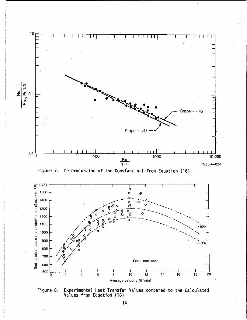
From Figure 7, the slope (n-1) 'has an average value of -0.465; and the constants b and e were 0.535 and 0.465,. respec- t i v e l y . The constant e has a value o f 1/3 def ined by the 3-factor. The constant d i s 0.535 a f t e r some algebraic ca lcu lat ion. The constants a and f were determined t o be 1.823 2 10% and 0.2 , respect ive ly , by t r ia l -and-er ro r method t o f i t our experimental data (see Figure 8). Subs t i tu t ion o f these constants i n t o equation (11) gives:
Nu = (1.823 2 .182) ( % ) O e 2 Ret 0.535 pr1/3 (,0.535m (1,E)0.465)(18)
This co r re la t i on i s v a l i d when poros i ty i s between 0.4 and 0.76. When
po ros i t y i s above 0.76, a cor rec t ion has been made t o adapt the equation t o the observed maximum when the outside heat t rans fe r c o e f f i c i e n t i s p l o t t e d against v e l o c i t y o r poros i ty .
13
Slope = -.45
Slope = -.48 -J’
- - - -
.01 , I I I 1 I 1 1 1 1 I I I I I I l l 1 1 I I I I I I 100 1000 10.000
Re - 1 - c INEL-A-4251
Figure 7. Determination of the Constant n-1 from Equation (16)
Figure 8. Experimental Heat Transfer Values compared to the Calculated Values from Equation (18)
14

NU = (1 .8~3 2 . Table I compares the values of the constants determined by our
work w i t h those obtained by other investigators. The correlation is similar t o Hamilton's, bu t a comparison of Nu numbers shows an average deviation o f -40% for Hamilton and Brea. The Richardson equation gives a 60% higher value, yields different curve shapes,and the maxi- mum occurs near a porosity of 0.65. l7
Table I
Comparison of Coefficients for Equation (11) Using Different
INEL W/A Bundle o f Tubes
1.823 0.535 1/3 0.535m 0.465 0.2
--
Experimental 'Data and Methods o f Correlation Hami 1 ton I s
Smith
INEL Hamilton Form of W/Si ng l e & Wasmumd & Coiled Tubes Brea
1.48 0.943 3.38 0.535 0.55 0.565 1/3 0.52 1/3 0.535m 0.55m 0.656m 0.465 ' 0.45 0.435 0.2 0.15 0.57
Richardson e t a1
0.67 0.62 113 0.62m-1 0.38 -0-
15
1. Staged Flow
Because of rapid mixing in a dense-phase 1 iquid-fluidjzed-bed, the Changes in shell-side temperature distribution approaches isothermal.
Cflation patterns do cause temperature variations wi-thin the bed, but %he isothermal approximation adequately describes the heat exchanger behavior.
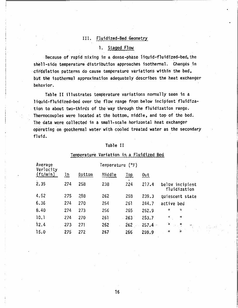
Table I1 illustrates temperature variations normally seen in a liquid-fluidized-bed over the flow range from below incipient flu-idita- tion to about two-thirds of the way through the fluidization range. Thermocouples were located at the bottom, middle, and top of the bed. The data were collected in a small-scale horizontal heat exchanger operating on geothermal water with coiled treated water as the secondary fluid.
Table I1
Temperature Variation in a Fluidized Bed
Average Verlocity (ft/min)
2.35
4.52
6.36 8.40 10.1 12.4 15.0
In
274
2 75 274 274 2 74 273 2 75
- Bottom
258
270 273 270 271 272
Temperature (OF)
Middl e
238
262 254 256
261 262 267
Top
224
258 261 265
263 262 266
out
21 7.4
239.3 244.7 252.9
253.7 257.4 259.9
- belox incipient
f 1 u i di rat i on quiescent state active bed
II tl
II 11
11 * I1
II i t
As seen i n Table l I , below the point o f fluidization, or when the bed i s i n a quiescent s ta te , the temperature pEofile i s normal, i .e . , the bottom temperature is highest and the top the lowest. Between velocities of 6 feet per minute and 12 feet per minute, the top and middle bed temperatures were inverted. This i s due t o circulation patterns established i n the bed. Above 12 feet per minute, the top and middle temperatures o f the bed are isothermal due t o vigorous mixing. tom temperature remains h i g h indicating less mixing.
The bot-
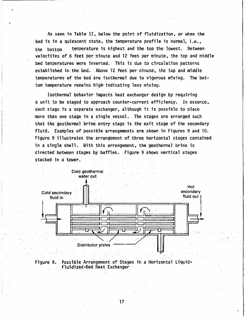
Isothermal behavior impacts heat exchanger design by requiring a unit t o be staged t o approach counter-current efficiency. each stage i s a separate exchanger, although i t is possible t o place more t h a n one stage in a single vessel. The stages are arranged such t h a t the geothermal brine entry stage is the exi t stage o f the secondary fluid. Examples of passibfe.arrangements are shown in Figures 9 and 10. Figure 9 i l lus t ra tes the arrangement of three horizontal stages contained in a single shell. directed- between stages by baffles. Figure 9 shows vertical stages stacked i n a tower.
In essence,
With this arrangement, the geothermal brine is
Cold geothermal water out
Figure 9. Possfble Arrangement of Stages i n a Horizontal Liquid- fluidized-Bed Heat Exchanger
17

i
Coolant flow Tube bundle
Stage n
Stage n + 1
I Geothermal
flow
Figure 10. Vertical’ Liquid-Fluidized-Bed Arrangement with the Geothermal Fluid Routed Internally Between Stages
18
,
Cost, efficiency, and brine velocity must be considered when de- termining the number of stages for a heat exchanger. the number of stages, the efficiency increases, requiring less total heat transfer surface. Efficiency approaches true counter-current efficiency asymptotically. the cost linearly. An optfmum is re'ached when adding a stage balances the cost saving in tube surface with the increased cost' stage.
By increasing
However, increasing the number of stages increases
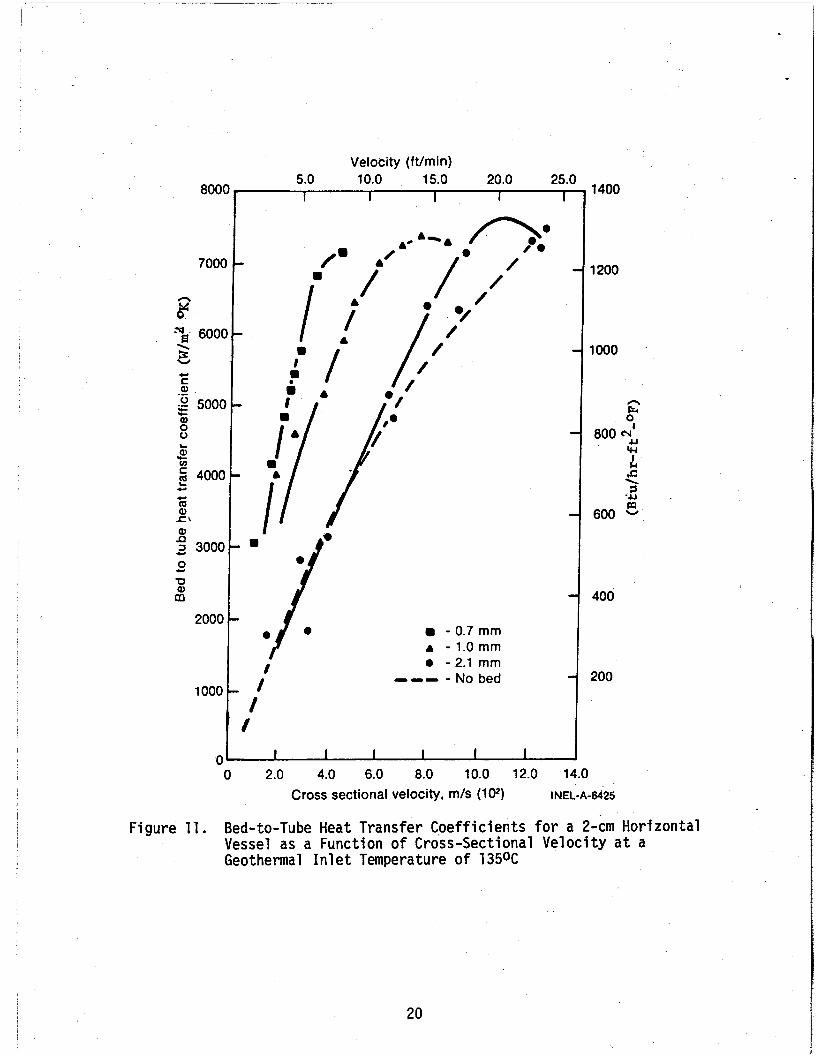
Each stage is limited in cross-sectional area by the velocity requirement. The brine velocity through the shell-side is limited by the window bounded by incipient fluidization and terminal velocity. However, to operate near the maximum heat transfer coefficient, the 1 imitation is more severe. heat transfer coefficients as a function of velocity and particle size. For each particle sIze,there exists a velocity which produces a maximum heat transfer cdefficjent. This occurs near'the porosity of 0.7 to 0.75.
Figure 1 1 shows experimental bed -to-tube
Figure 6 relates particle size to velocity and porosity. The cross-sectional area of a stage must be arranged such that the +hid velocity allows particles to be in the porosity range of 0.7 to 0.75. Not only velocity, but particle size is an important design parameter.
2. F1 ow Di s tri bu ti on Sys tems
Fluidization depends on fluid velocity, and uniform fluidization depends a7 a unifotm crossTsectiona1 velocity profile. Uniform velocity is provided by distributing the flow beneath the tube bundle-and bed. Fluid enters the bottom of the shell via a pipe or manifold. The flow is partially dispersed in the plenum. In this segment of the shell* the flow cross sett'lbn is increased from the cross-sectional area of the delivery system to the cross section of the support-distribution plate.
The support-distribution plate supports the bed and is the final part of the flow distribution system. The simplest system consists of a single perforated plate with the perforation diameter smaller than the particle diameter. This system is limited to non-scaling brines since small perforations are easily plugged.
19
800(
700C
n M 0
“Js 600( 2 c C Q, .- 8 500C
z g 4000
r Q, 0 0
.c u)
c c Q Q, SCI Q,
c =I 3000 0
-0 Q,
c
m 2000
1000
0
Ve tocity (ft/m i n) 5;O lq.0 1:.0 2q.O 270 , 1400
I
I) A ‘7
’/ e I
I I
f
- 0.7 mm A - 1.0 mm 0 - 2.1 mm --- - No bed
1 400
1 2oo 0 2.0 4.0 6.0 8.0 10.0 12.0 14.0
Cross sectional velocity, m/s (107 INEL-A-612S
Figure 11. Bed-to-Tube Heat Transfer Coefficients for a 2-cm Horizontal Vessel as a Function of Cross-Sectional Velocity a t a Geothermal Inlet Temperature of 1 3 5 O C
20
----
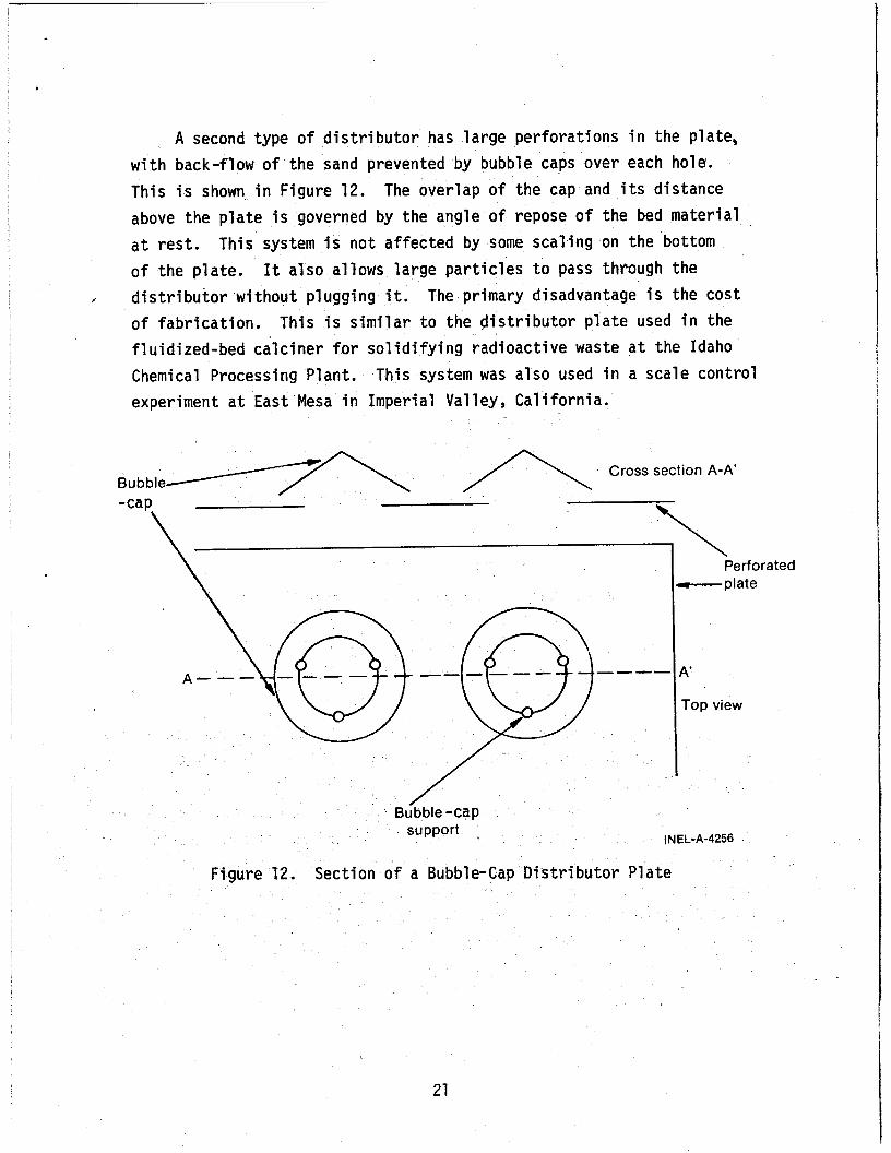
21
Perforated -plate
A'
Top view
Gas. fluidized .beds maintain the most uniform fluidization when the pressure drop across the distributor plate is 40% of the pressure drop across the bed. A similar rule of thumb is not yet available for liquid-fluidized-beds, b u t work i s proceeding i n this direction. drop across the d i s t r i b u t o r represents a parasitic pumping cost, and needs t o be minimized.
Pressure
3. Tube Arrangement
The two designs under consideration for liquid-fluidized-bed heat exchangers present separate problems i nvol v i ng f 1 ow around tubes. The vertical design contains a vertical tube bundle with parallel flow characteristics. In this case fluid velocity is constant on the shell-side.
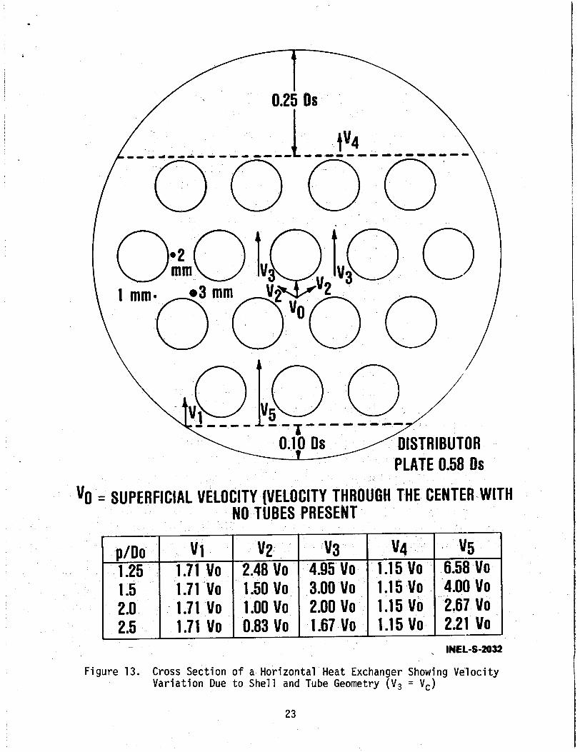
Horizontal vessel design presents more complex problems because o f the cross-flow nature and variable cross section.l8 Figure 13 shows the relative velocities in the cross section of a horizontal vessel. DS is the diameter of the shell and Do the diameter of the tubes. in various parts of the vessel are shown as a function of pitch-to-tube diameter ra t io . velocity a t the bottom of the exchanger could exceed terminal velocity M1e't.k top of the bed appears normal. exchangers, i t is imperative t o calculate the maximum velocityiis well as the cross-sectional velocity.
Velocities
Variable velocity creates the s i tua t ion where the
When designing horizontal
Conventional tube-and-she1 1 heat exchangers have a p i tch-to-tube diameter ra t io of about 1.25. T h i s i s undesirable i n liquid-fluidized- bed heat exchangers because the particle size becomes a significant
22
A combination distributor simulates natural 1 iqu id fluidized beds found in quicksand. or steel bal ls which are relatively stationary, b u t distribute the flow. fully i n bench-scale experiments. pebble bed. During flow conditions there is enough agitation in the pebble bed t o prevent scale formation i n the distr butor . The major disadvantage of this system i s added weight , which increases support costs .
In this systemsthe plenum is f i l l ed w i t h pebbles
T h i s system' i s known as a pebble bed and has been used success- A t res t the bed is supported by the
"0
, IN€L-S-2032
Figure 13. Cross Sec t ion o f a Hor Var ia t ion Due t o Shel l
zonta l Heat Exchanger Showing Veloc i ty and Tube Geometry (V, = Vc)
23
fraction of the distance between tubes. Also, the velocity between tubes becomes 1 arge.
Another problem created by cross-flow i n horizontal vessels is the area of very low velocity directly above a tube. streaming past the tubes creates a pile of particles resting on top of the tubes. These areas are dead as fa r as heat transfer is concerned, and are potential locations for corrosive attack. Two possible methods of eliminating this problem are t o induce internal circulation by means of baffles or t o use spiral fluted tubing. niques have not been performed.
In model u n i t s ,
Tests of these tech-
4. Proportioning rubes - Disengagement Space
One technique for providing more uniform flow velocities i n hori- zontal exchangers is t o vary the p i tch-to-tube diameter ra t io proportional t o the cross sectional area. A t the bottom of the vessel the tubes would be spread about 33% further apart t o produce the same velocity as seen a t the midpo in t cross section.
Disengagement space above the top of the bed must be designed i n t o the heat exchanger. particulate fluidization, the interface is definite and constant, b u t a small fraction of particles will have sufficient velocity t o escape the top of the bed,and sufficient head room must be allowed for them t o decelerate and drop back t o the bed. Two to three inches is sufficient in a vertical vessel i f the distribution i s uniform. However, as a safety factor 5 t o 6 inches i s usually allowed. the current convention i s t o allow 25% of the vessel diameter a t the top for disengagement. top of the vessel. allow less head space because there i s a normal drop i n velocity above the top row o f tubes.
In liquid-fluidized-bed heat exchangers with
In horizontal vessels
This i s due t o increasing fluid velocity i n the With larger vessels i t may prove practical to
24
.
IV. Sample Design Problem
The design process for a liquid-fluidized-bed -heat exchanger is similar t o designing a conventional tube-and-shell exchanger. parameters which are not included i n shell-and-tube units must be i ncl uded :
Several
1. The dumbel- of stages. 2. Shell-side velocity and consequently the shell cross-sectional
area. 3. Particle size. 4. Flow d is t r ibu t ion . 5. Disengagement space.
Present information indicates t h a t a shell-side fouling factor is not required.
Parameters which are fixed include:
1. Brine inlet temperature. 2. Coolant inlet temperature. 3. Materials of construction.
Parameters which are varied t o minimize system cost include:
1. 2. 3. 4. Tube diameter. 5. Number of tube passes.
The design example considers a small liquid-liquid heat exchanger t h a t w o u l d be used as a preheater i n a small power system or i n a non- electric application. For the .example given, which corresponds t o a small pre- heater for a binary electric p l a n t , isobutane was used as the secondary f l u i d .
From the mass flow rate and required liquid isobutane velocity the
Brine outlet temperature and brine mass flow rate. Coolant outlet temperature and coolant mass flow rate. Coolant tube-side velocity and the number of tubes.
number of tubes are calculated. (3/8 inch), 18BWG tubes are required.
For this case thirty-five 0.95-cm
25
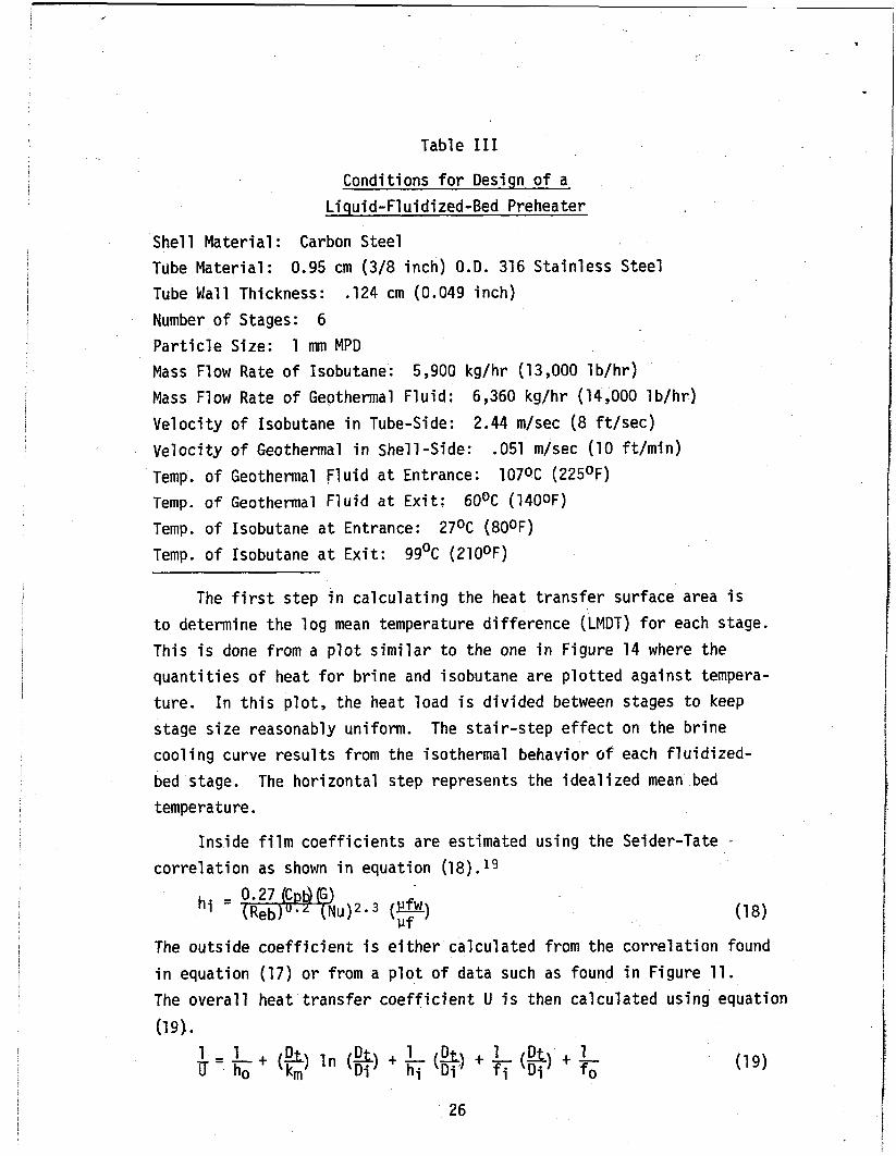
Table I11
Conditions for Design of a Liquid-Fluidized-Bed Preheater
She1 1 Material : Carbon Steel Tube Material: Tube Wall Thickness: Number of Stages: 6 Particle Size: 1 mm MPD Mass Flow Rate of Isobutane: Mass Flow Rate of Geothermal F l u i d : Velocity of Isobutane i n Tube-Side: Velocity of Geothermal i n Shell-Side: Temp. of Geothermal Fluid a t Entrance: Temp. o f Geothermal Fluid a t Exi t : Temp. of Isobutane a t Entrance: Temp. o f Isobutane a t Exi t :
0.95 cm (3/8 inch) O.D. 316 Stainless Steel .124 cm (0.049 inch)
5,900 kg /h r (13,000 l b / h r ) 6,360 kg/hr (14,000 l b / h r ) 2.44 m/sec (8 f t /sec)
.051 m/sec (10 ft/min) 107OC (225OF)
60% (140OF) 2 7 O C (80OF)
99OC ( 2 1 O O F )
The f irst step i n calculating the heat transfer surface area i s to determine the log mean temperature difference (LMDT) for each stage. T h i s is done from a plot similar to the one i n Figure 14 where the quantities of heat for brine and isobutane are plotted against tempera- ture. stage size reasonably uniform. cooling curve results from the isothermal behavior o f each fluidized- bed stage. The horizontal step represents the idealized mean bed temperature.
In this plot, the heat load is d iv ided between stages to keep The stair-step effect on the brine
Inside film coefficients are estimated u s i n g the Seider-Tate - correlation as shown i n equation (18).19
The outside coefficient is either calculated from the correlation found i n equation (17) or from a plot of data such as found i n Figure 11. The overall heat transfer coefficient U is then calculated u s i n g equation (19).
26

G e
160 -
150 -
140 -
130 -
120 -
Quantity of heat
Figure 14. D i v i s i o n o f Preheater i n t o S i x Stages; I n This Case D i v i s i o n i s Made t o Produce S i m i l a r S i z e Stages
27
In laboratory bench-scale experiments , the outside tube fouling 1 f0
resistance (-) was found t o be less thdn 5 x 10⁻⁶ M2kGJ w i t h a coil ex- changer i n synthetic brine. Normally this term is ignored. Inside fouling resistance for isobutane may be taken as 8.8 x M2k/W.
Using the value of the overall heat transfer coefficient ( U ) the heat transfer area ( A ) i s calculated using equation (20).
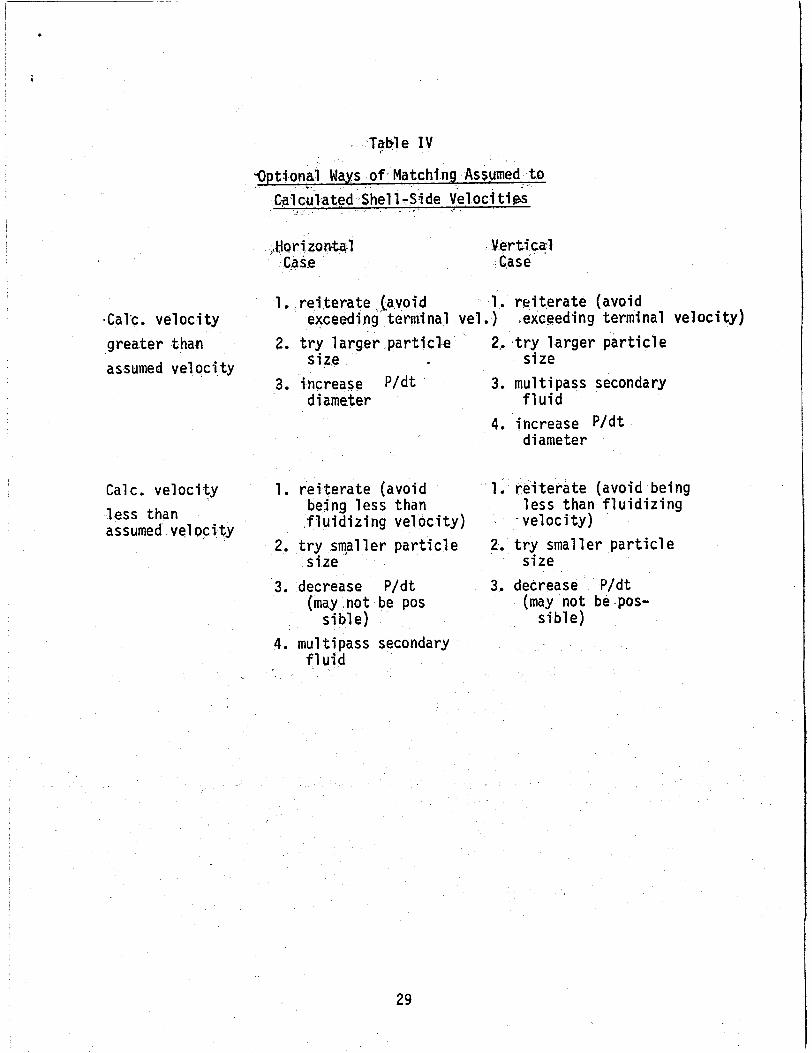
From the total required area, tube diameter, and number of tubes, the length of the tube bundle i s calculated. tubes and tube pitch, the diameter of the shell is calculated. The geothermal velocity i s then calculated and compared t o the value used i n determining the bed-to-tube heat transfer coefficient (ho). If the velocities vary, several options are available as shown i n Table IV,
From the number of
Care must be exercised i n reiterating t o velocities which are too high or too low. because i t i s close t o the heat transfer maximum. i s t o choose one o f the other techniques for closing the gap between
The assumed value of velocity is normally chosen The preferred method
the assumed and calculated velocity,and then rei terate t o fine tune.
For the 60 kW(e) pilot plant, three vertical stages and three horizon- tal stages were chosen; the calculated parameters are shown in Table IV. For demonstration only, three vertical stages and three horizontal stages were chosen t o achieve the six stages. would be o f the same type.
Normally, a l l stages
When compared t o conventional tube-and-shell exchangers designed for the same service, liquid-fluidized-bed heat exchangers require substantially less heat transfer surface. However, because of the higher pitch-to-tube diameter r a t io , the shells tend t o be larger, and consequently represent a greater fraction of the cost.
28
VCa1.c. velocity greater than assumed velocity
Cal c . vel oci ty less than assumed velocity
Table IV
‘Optional I . Ways of Matching Assumed t o C3lcu’lated Shell - . -S.ide Velocit ik
:.Horizontal Verticcl C3s.e C.ase
1. re i terate , Layoid 1. re i terate (avoid exceeding‘ terminal vel. ) .exceeding terminal velocity)
2. t ry larger particle
3. increase P / d t size
diameter
2,. , t r y larger particle size
3. mu1 t i pass secondary f luid
4. increase P / d t diameter
1. re i terate (avoid being less t h a n f 1 u i d i z i ng velocity)
2. t ry smaller particle size
3. decrease P /d t (may no t be pos
si bl e ) 4. mu1 tipass secondary
fluid
1, re i terate (avoid being less than f l u i d i z i n g
- vel oci ty ) 2. t r y smaller particle
3. decrease - P/dt
s ible)
size
(may not be pos-
29
.
Table V
Six-Stage, Six-Pass Liquid-Fluidized-Bed Preheater for a 60 kYe) Geothermal Power Plant
Stage Stage Stage Stage Stage Stage , No. No. No. No. No. No.
Temp. of liquid isobutane at 92 82 70 58 43 27 entrance (OC)
exit (OC)
mal fluid (OC)
Temp. of liquid isobutane at 99 92 82 70 58 43 i
Isothermal temp. of geothep 105 99 92 84 76 66
Quantity of heat exchanged 3.48~ 4.68~ 5.83~ 5.83~ 6.96~ 8.04~
LMTD (OC) 9.20 11.7 15.5 20.0 24.3 29.8
ho geothermal fluid film 6640 6691 6640 6640 6640 6640
hi liquid isobutane film 4142 4319 4194 4068 3978 3257
U overall heat transfer 1782 1827 1793 1765 1742 1702
Heat transfer area (m2) 2.11 2.20 2.09 1.65 1.65 1.59 Effective tube length (m) 2.01 2.10 1.99 1.57 1.57 1.51 Tube length per pass (m) .335 .349 .333 .338 .262 .251 Shell inside diameter (m) .254 .254 .254 .254 .254 .254
(W) 104 104 104 104 104 104
coefficient ( W/m2k)
coe f f i ci en t ( W/m2 k )
coefficient ( W/m2 k)
30
i
Ref ere nee s
1. Hogg, G.W. and Grimmett, E.S. 'I
fer i n .a Liquid F lu id i zed Bed", 62 (67), 1966.
I 2. Botterill, S. S. M., Flufd Bed Heat Transfer, Academic Press, 1975.
3. P a t e l , R. D. and Simpson, J. M., Chem Eng. Sc i . , 32, 76, '1977. Y
I 4: Trupp, A. C., "A Review of F l u i d i z a t i o n Relevant t o a Liquid 'F lu id- , i zed Bed Nuclear Reactor", N i theshe l l Nuclear Establ ishment , P i n -
awa, Manitoba, Oct. 1967.
5. Wagner, K. L., Prel imfnary Study o f Amorphous S i l i c a Deposition i n a Bench S c a l e Liquid F lu id i zed Bed Heat Exchanger, presented t o the S c a l e Management i n Geothermal Energy Developwnt Confer- ence, 1976.
Grimmett, E. S. "A Method o f Determining Volumes and Sur-face Areas for Groups of Won-Uniform Sized Particles. AEC Research and Devef- -
opment Report IDO-14617, 1963.
Lewis, E.1.I. and Bowerman, E. W. " F l u i d i z a t i o n of S o l i d P a r t i c l c s i n Liquid", Chein. Eng. Progr. 49, 12, 1952, pp 603.
6.
7.
8. Richardson, J. F. and Zaki, W. N., Trans. Inst, Chem. Engrs., 32, 35, 1954.
I 9.
10.
Nilhelm, R. H. , Mooson Kwauk, " F l u i d i t a t i o n o f S o l i d Particles", CIP.E., Vol. 44, No. 3, 1948, pp 201.
Hamilton, William, "A C o r r e l a t l o n f o r Heat T rans fe r i n L i q u i d Fluidized Beds", Can. 3. Chem, Engng., Vol. 48, 1970, pp-52.
12. Richardson, 3. F., M.N. Roman!, K. J. S h a k i r i , "Heat Trans fe r from Immersed Sur faces i n Liqui F lu id ized Bed", C*etn. Engng. Sci., Vol. 31, 1976, pp 614.
F l u i d i z i n g Agent and the S o l i d P a r t i c l e s o f Flu id ized Beds", FIP-tr-538, U.K.A,E.A., 1960.
F lu id i zed Bed", C.P.E. , Vol. 49, No. 3, 1953, pp 141.
13. Ruckenstein, E., I . Teoreanu, "On Heat o r Mass T r a n s f e r Batween the h
14. Chu, J. C., James K a l i l , William A. Wetteroth, "Mass T r a n s f e r i n 4
31
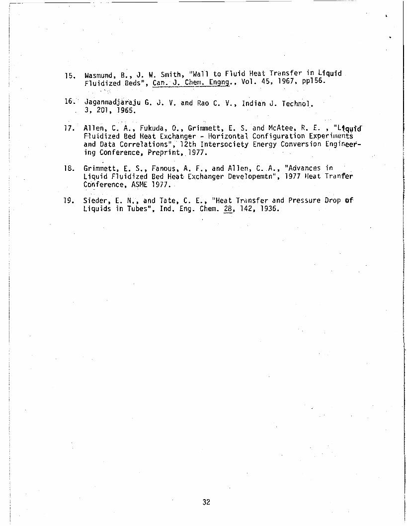
15. Wasmund, B. , J. W. Smith, "Wall t o F l u i d Heat T r a n s f e r i n Liquid F l u i d i z e d Beds", Can. J. Cheni. Engng., Vol. 45, 1967, pp156.
16. J a g a n n a d j a r a j u G. 3. V . and Rao C. V . , I n d i a n J. Technol. , 3 , 201, 1965.
17. A l l e n , C. A . , Fukuda, O., Grinunett, E. S . and McAtee, R . E . , "Liqyjtf F.luidized Bed Heat Exchanger - H o r i z o n t a l C o n f i g u r a t i o n Experiiiients and Data C o r r e l a t i o n s " , 1 2 t h I n t e r s o c i e t y Energy Conversion Engineer- i n g Conference, P r e p r i n t , 1977.
18. Griminett, E. S., Fanous, A. F . , and Allen, C. A . , "Advances i n Liquid F l u i d i z e d Bed Heat Exchanger Developemtn", 1977 l lea t TranPer Conference, ASME 1977.
L i q u i d s i n Tubes", Ind. Eng. Chem. - 28, 142, 1936. 19. S i e d e r , E. N . , and T a t e , C . E . , "Heat Tr i rnsfer and Pressure Drop bf
32
1
.
Nomenclature
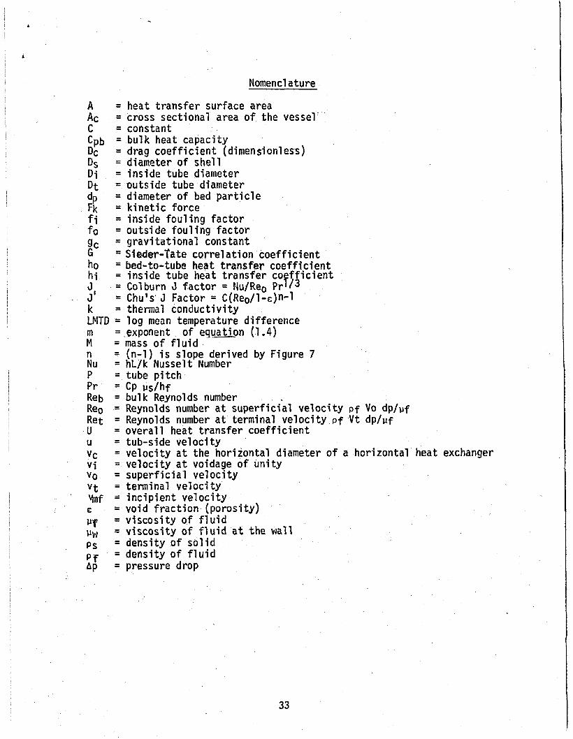
A = heat transfer surface area Ac C = constant Cpb = b u l k heat capacity Dc = drag coefficient (dimensionless) Ds = diameter of shell D i = inside tube diameter D t = outside tube diameter dp Fk = kinetic force f i = inside fouling factor f o = outside fouling factor gc = gravitational constant G = Siuer-Tate correlation coefficient ho h i J
- J' = Chu's'J Factor = C(Reo/l-E)n-l k = thermal conductivity LMTD = l og mean temperature difference m = exponent of equation (1.4) M = mass of f l u i d n Nu = hL/k Nusselt Number P = tube pitch Pr = CP vs/hf Reb = b u l k Reynolds number Reo = Reynolds number a t superficial velocity pf Vo dp/pf Ret = Reynolds number a t terminal velocity pf V t dp/pf U = overall heat transfer coefficient U = tub-s ide velocity vc = velocity a t the horizontal diameter o f a horizontal heat exchanger v i = velocity a t voidage of unity V o = superficial velocity v t = terminal velocity hf = incipient velocity E = void fraction (porosity) p~ = viscosity of f l u i d uw ps = density of sol id p f = density of f l u i d Ap = pressure drop
= cross sectional area of the vessel
= diameter of bed particle
= bed-to-tube heat transfer coefficient = inside tube heat transfer co ff ic ient = Colburn J factor = FJu/Reo Pr e i 3
= (n-1) is slope derived by Figure 7
,
= viscosity of f l u i d a t the wall
-
33

?
t

\
DISTRIBUTION RECORD FOR 5CP-’1153
Internal Distribution
1 - Chicago Patent Group 9800 South Cass Argonne, IL 60439
Office - DOE 83401
3 - ti. P. Pearson Information Management, EG&G
IO - INEL Technical Library
45 - Author
External Distribution
531 - Distrjbution under UC-66d - GE: Utilization Technology
45 - Special .External L
Total Copies Printed: 634
I