iCnd2 exam Updates - pearsoncmg.comptgmedia.pearsoncmg.com/imprint_downloads/cisco/... · iCnd2...
12
APPENDIX B ICND2 Exam Updates Over time, reader feedback allows Cisco Press to gauge which exam topics give our readers the most problems. In addition, Cisco may make small changes in the breadth of exam topics or in emphasis of certain topics. To assist readers with those topics, the author creates new materials to clarify and expand on those challenging exam topics. The document you are reading is Version 2.0 of this appendix. The original version (1.0) contained no technical topics; Version 2.0 includes detail about the Rapid Spanning Tree Protocol (RSTP). You can check for an updated version of this appendix at http://www.ciscopress.com/ title/9781587143731. Rapid STP (IEEE 802.1w) Concepts As described in detail in Chapters 1 and 2, the IEEE defines STP in the 802.1D IEEE stan- dard. The IEEE improved the 802.1D protocol with the definition of RSTP, as defined in standard 802.1w. RSTP (802.1w) works just like STP (802.1D) in several ways: n It elects the root switch using the same parameters and tiebreakers. n It elects the root port on nonroot switches with the same rules. n It elects designated ports on each LAN segment with the same rules. n It places each port in either forwarding or blocking state, although RSTP calls the blocking state the discarding state. RSTP can be deployed alongside traditional 802.1D STP switches, with RSTP features work- ing in switches that support it, and traditional 802.1D STP features working in the switches that support only STP. With all these similarities, you might be wondering why the IEEE bothered to create RSTP in the first place. The overriding reason is convergence. STP takes a relatively long time to converge (50 seconds with the default settings when all the wait times must be followed). RSTP improves network convergence when topology changes occur, usually converging within a few seconds (or in slow conditions, in about 10 seconds). IEEE 802.1w RSTP changes and adds to IEEE 802.1D STP in ways that avoid waiting on STP timers, resulting in quick transitions from forwarding to blocking state and vice versa.
Transcript of iCnd2 exam Updates - pearsoncmg.comptgmedia.pearsoncmg.com/imprint_downloads/cisco/... · iCnd2...
Appendix B
iCnd2 exam UpdatesOver time, reader feedback allows Cisco Press to gauge which exam topics give our readers the most problems. In addition, Cisco may make small changes in the breadth of exam topics or in emphasis of certain topics. To assist readers with those topics, the author creates new materials to clarify and expand on those challenging exam topics.
The document you are reading is Version 2.0 of this appendix. The original version (1.0) contained no technical topics; Version 2.0 includes detail about the Rapid Spanning Tree Protocol (RSTP).
You can check for an updated version of this appendix at http://www.ciscopress.com/title/9781587143731.
Rapid STp (ieee 802.1w) ConceptsAs described in detail in Chapters 1 and 2, the IEEE defines STP in the 802.1D IEEE stan-dard. The IEEE improved the 802.1D protocol with the definition of RSTP, as defined in standard 802.1w.
RSTP (802.1w) works just like STP (802.1D) in several ways:
n It elects the root switch using the same parameters and tiebreakers.
n It elects the root port on nonroot switches with the same rules.
n It elects designated ports on each LAN segment with the same rules.
n It places each port in either forwarding or blocking state, although RSTP calls the blocking state the discarding state.
RSTP can be deployed alongside traditional 802.1D STP switches, with RSTP features work-ing in switches that support it, and traditional 802.1D STP features working in the switches that support only STP.
With all these similarities, you might be wondering why the IEEE bothered to create RSTP in the first place. The overriding reason is convergence. STP takes a relatively long time to converge (50 seconds with the default settings when all the wait times must be followed). RSTP improves network convergence when topology changes occur, usually converging within a few seconds (or in slow conditions, in about 10 seconds).
IEEE 802.1w RSTP changes and adds to IEEE 802.1D STP in ways that avoid waiting on STP timers, resulting in quick transitions from forwarding to blocking state and vice versa.
658 CCNA ICND2 200-101 Official Cert Guide
Specifically, RSTP, compared to STP defines more cases in which the switch can avoid waiting for a timer to expire, such as the following:
n Adds a new mechanism to replace the root port, without any waiting to reach a forward-ing state (in some conditions)
n Adds a new mechanism to replace a designated port, without any waiting to reach a for-warding state (in some conditions)
n Lowers waiting times for cases in which RSTP must wait.
For instance, when a link remains up, but Hello bridge protocol data units (BPDU) simply stop arriving regularly on a port, STP requires a switch to wait for MaxAge seconds. STP defines the MaxAge timers based on 10 times the Hello timer, or 20 seconds, by default. RSTP shortens this timer, defining MaxAge as three times the Hello timer.
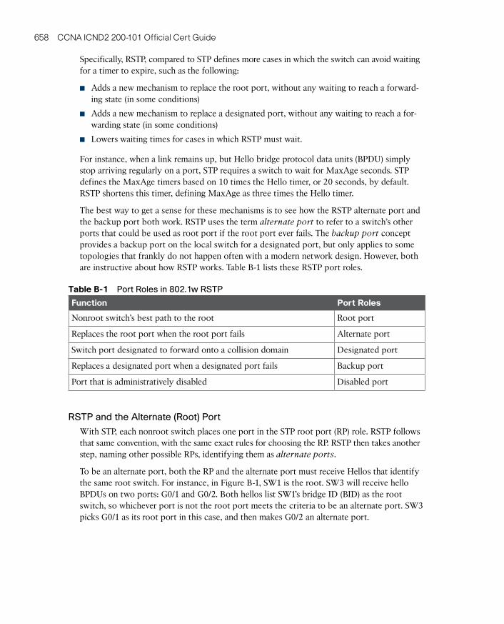
The best way to get a sense for these mechanisms is to see how the RSTP alternate port and the backup port both work. RSTP uses the term alternate port to refer to a switch’s other ports that could be used as root port if the root port ever fails. The backup port concept provides a backup port on the local switch for a designated port, but only applies to some topologies that frankly do not happen often with a modern network design. However, both are instructive about how RSTP works. Table B-1 lists these RSTP port roles.
Table B-1 Port Roles in 802.1w RSTP
Function port Roles
Nonroot switch’s best path to the root Root port
Replaces the root port when the root port fails Alternate port
Switch port designated to forward onto a collision domain Designated port
Replaces a designated port when a designated port fails Backup port
Port that is administratively disabled Disabled port
RSTP and the Alternate (Root) Port
With STP, each nonroot switch places one port in the STP root port (RP) role. RSTP follows that same convention, with the same exact rules for choosing the RP. RSTP then takes another step, naming other possible RPs, identifying them as alternate ports.
To be an alternate port, both the RP and the alternate port must receive Hellos that identify the same root switch. For instance, in Figure B-1, SW1 is the root. SW3 will receive hello BPDUs on two ports: G0/1 and G0/2. Both hellos list SW1’s bridge ID (BID) as the root switch, so whichever port is not the root port meets the criteria to be an alternate port. SW3 picks G0/1 as its root port in this case, and then makes G0/2 an alternate port.

B
Appendix B: ICND2 Exam Updates 659
Gi0/1
Gi0/1
Gi0/2
Gi0/2Gi0/1
Gi0/2SW1
SW3
SW2
Legend:
– Root Port– Alternate Port– Discarding State– Failing Link
Root DP RP
RP
DP DP
RPALT
ALT
Root is SW1I am SW2Root Cost = 4
Root is SW1I am SW1Root Cost = 0
Figure B-1 Example of SW3 Making G0/2 Become an Alternate Port
An alternate port basically works like the second-best option for root port. The alternate port can take over for the former root port, often very rapidly, without requiring a wait in other interim RSTP states. For instance, when the root port fails, or when hellos stop arriving on the original root port, the switch moves the original root port to a disabled role and transi-tions to a discarding state (the equivalent of STP’s blocking state). Without waiting on any timers, the best alternate port then becomes the new root port. That new root port also does not need to spend time in other states, like learning state, instead moving immediately to forwarding state.
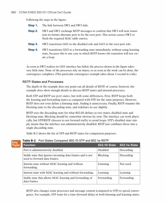
Figure B-2 shows an example of RSTP convergence in which the link between SW1 and SW3 fails. The figure begins with Step 1 as the event that causes the link to fail.
Gi0/1
Gi0/1
Gi0/2
Gi0/2Gi0/1
RSTP
ImmediateChange toForwarding
Gi0/2SW1
SW3
SW2
Legend:
– Root Port– Alternate Port– Discarding State– Failing Link
12
3
4
Root DP RP
RP
DP DPALT
RPALT
Figure B-2 Convergence Events with SW3 G0/1 Failure
660 CCNA ICND2 200-101 Official Cert Guide
Following the steps in the figure:
Step 1. The link between SW1 and SW3 fails.
Step 2. SW3 and SW2 exchange RSTP messages to confirm that SW3 will now transi-tion its former alternate port to be the root port. This action causes SW2 to flush the required MAC table entries.
Step 3. SW3 transitions G0/1 to the disabled role and G0/2 to the root port role.
Step 4. SW3 transitions G0/2 to a forwarding state immediately, without using learning state, because this is one case in which RSTP knows the transition will not cre-ate a loop.
As soon as SW3 realizes its G0/1 interface has failed, the process shown in the figure takes very little time. None of the processes rely on timers, so as soon as the work can be done, the convergence completes. (This particular convergence example takes about 1 second in a lab.)
RSTP States and Processes
The depth of the example does not point out all details of RSTP, of course; however, the example does show enough details to discuss RSTP states and internal processes.
Both STP and RSTP use port states, but with some differences. First, RSTP keeps both the learning and forwarding states as compared with STP, for the same purposes. However, RSTP does not even define a listening state, finding it unnecessary. Finally, RSTP renames the blocking state to the discarding state, and redefines its use slightly.
RSTP uses the discarding state for what 802.1D defines as two states: disabled state and blocking state. Blocking should be somewhat obvious by now: The interface can work physi-cally, but STP/RSTP chooses to not forward traffic to avoid loops. STP’s disabled state sim-ply meant that the interface was administratively disabled. RSTP just combines those into a single discarding state.
Table B-2 shows the list of STP and RSTP states for comparison purposes.
Table B-2 Port States Compared: 802.1D STP and 802.1w RSTP
Function 802.1d State 802.1w State
Port is administratively disabled. Disabled Discarding
Stable state that ignores incoming data frames and is not used to forward data frames.
Blocking Discarding
Interim state without MAC learning and without forwarding.
Listening Not used
Interim state with MAC learning and without forwarding. Learning Learning
Stable state that allows MAC learning and forwarding of data frames.
Forwarding Forwarding
RSTP also changes some processes and message content (compared to STP) to speed conver-gence. For example, STP waits for a time (forward delay) in both listening and learning states.
B
Appendix B: ICND2 Exam Updates 661
The reason for this delay in STP is that, at the same time, the switches have all been told to time out their MAC table entries. When the topology changes, the existing MAC table entries may actually cause a loop. With STP, the switches all tell each other (with BPDU messages) that the topology has changed, and to time out any MAC table entries using the forward delay timer. This removes the entries, which is good, but it causes the need to wait in both listening and learning state for forward delay time (default 15 seconds each).
RSTP, to converge more quickly, avoids relying on timers. RSTP switches tell each other (using messages) that the topology has changed. Those messages also direct neighboring switches to flush the contents of their MAC tables in a way that removes all the potentially loop-causing entries, without a wait. As a result, RSTP creates more scenarios in which a for-merly discarding port can immediately transition to a forwarding state, without waiting, and without using the learning state, as shown in the example in Figure B-2.
RSTP Backup (Designated) Ports
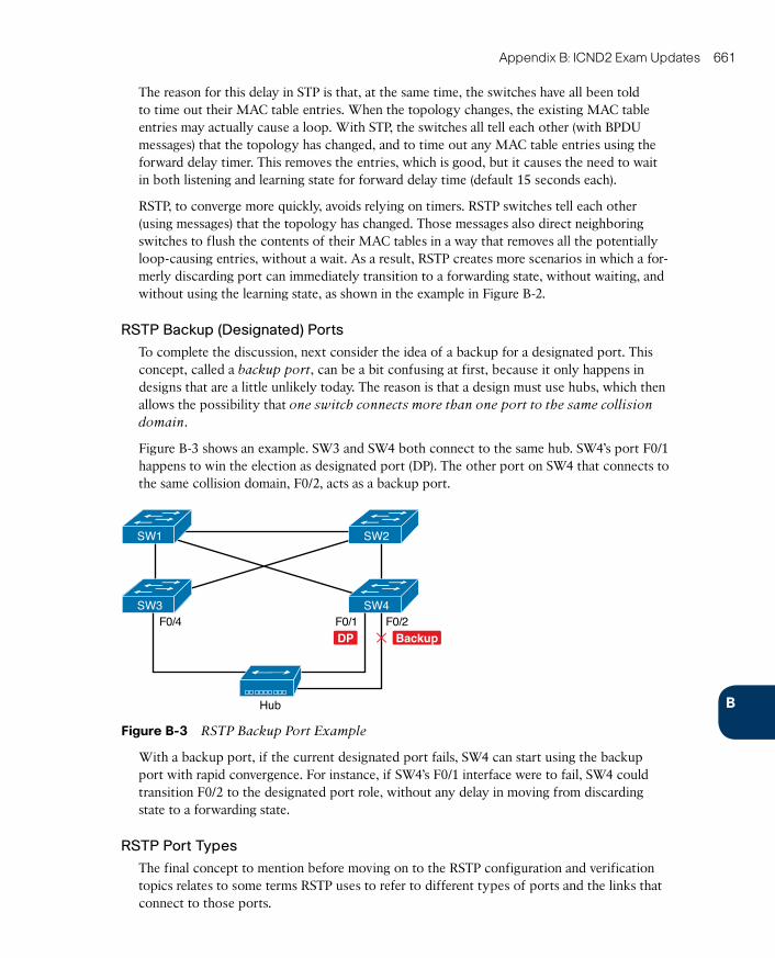
To complete the discussion, next consider the idea of a backup for a designated port. This concept, called a backup port, can be a bit confusing at first, because it only happens in designs that are a little unlikely today. The reason is that a design must use hubs, which then allows the possibility that one switch connects more than one port to the same collision domain.
Figure B-3 shows an example. SW3 and SW4 both connect to the same hub. SW4’s port F0/1 happens to win the election as designated port (DP). The other port on SW4 that connects to the same collision domain, F0/2, acts as a backup port.
SW1
SW3
SW2
F0/1F0/4 F0/2SW4
Hub
DP Backup
Figure B-3 RSTP Backup Port Example
With a backup port, if the current designated port fails, SW4 can start using the backup port with rapid convergence. For instance, if SW4’s F0/1 interface were to fail, SW4 could transition F0/2 to the designated port role, without any delay in moving from discarding state to a forwarding state.
RSTP Port Types
The final concept to mention before moving on to the RSTP configuration and verification topics relates to some terms RSTP uses to refer to different types of ports and the links that connect to those ports.
662 CCNA ICND2 200-101 Official Cert Guide
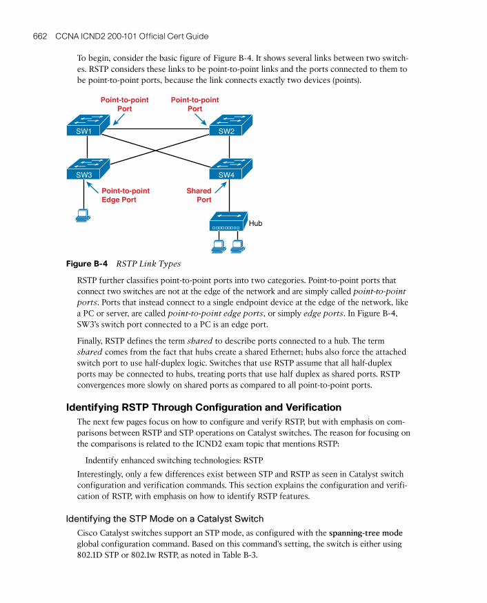
To begin, consider the basic figure of Figure B-4. It shows several links between two switch-es. RSTP considers these links to be point-to-point links and the ports connected to them to be point-to-point ports, because the link connects exactly two devices (points).
SW1
SW3
SW2
SW4
Hub
Point-to-pointEdge Port
SharedPort
Point-to-pointPort
Point-to-pointPort
Figure B-4 RSTP Link Types
RSTP further classifies point-to-point ports into two categories. Point-to-point ports that connect two switches are not at the edge of the network and are simply called point-to-point ports. Ports that instead connect to a single endpoint device at the edge of the network, like a PC or server, are called point-to-point edge ports, or simply edge ports. In Figure B-4, SW3’s switch port connected to a PC is an edge port.
Finally, RSTP defines the term shared to describe ports connected to a hub. The term shared comes from the fact that hubs create a shared Ethernet; hubs also force the attached switch port to use half-duplex logic. Switches that use RSTP assume that all half-duplex ports may be connected to hubs, treating ports that use half duplex as shared ports. RSTP convergences more slowly on shared ports as compared to all point-to-point ports.
identifying RSTp Through Configuration and VerificationThe next few pages focus on how to configure and verify RSTP, but with emphasis on com-parisons between RSTP and STP operations on Catalyst switches. The reason for focusing on the comparisons is related to the ICND2 exam topic that mentions RSTP:
Indentify enhanced switching technologies: RSTP
Interestingly, only a few differences exist between STP and RSTP as seen in Catalyst switch configuration and verification commands. This section explains the configuration and verifi-cation of RSTP, with emphasis on how to identify RSTP features.
Identifying the STP Mode on a Catalyst Switch
Cisco Catalyst switches support an STP mode, as configured with the spanning-tree mode global configuration command. Based on this command’s setting, the switch is either using 802.1D STP or 802.1w RSTP, as noted in Table B-3.

B
Appendix B: ICND2 Exam Updates 663
Table B-3 Cisco Catalyst STP Configuration Modes
parameter on spanning-tree mode Command
Uses STp or RSTp?
protocol Listed in Command Output
description
pvst STP ieee Default; per-VLAN spanning-tree instance
rapid-pvst RSTP rstp Like PVST, but uses RSTP rules instead of STP for each STP instance
mst RSTP mst Creates multiple RSTP instances but does not require 1 instance per each VLAN
To determine whether a Cisco Catalyst switch uses RSTP, you can look for two types of infor-mation. First, you can look at the configuration, as noted in the left column of the table. Also, some show commands list the STP protocol as a reference to the configuration of the spanning-tree mode global configuration command. A protocol of rstp or mst refers to one of the modes that uses RSTP, and a protocol of ieee refers to the mode that happens to use STP.
Before looking at an example of the output, review the topology in Figure B-5. The remain-ing RSTP examples in this appendix use this topology. In the RSTP examples in this appen-dix, SW1 will become root, and SW3 will block on one port (G0/2), as shown.
LarryFa0/11
Gi0/1
Gi0/1
Gi0/2
Gi0/2SW2
SW3
Gi0/1
Gi0/2SW1
Fa0/12Archie
Bob
Fa0/13
DPDP
DP
DP
DP DP
RP
– Designated Port
RP
Legend: – Root PortDPRP
– Blocking Port
Root
Figure B-5 Network Topology for STP and RSTP Examples
The first example focuses on VLAN 10, with all switches using 802.1D STP and the default setting of spanning-tree mode pvst. This setting creates an instance of STP per VLAN (which is the per-VLAN part of the name) and uses 802.1D STP. Each switch places the port connected to the PC into VLAN 10 and enables both PortFast and BPDU Guard. (See Chapter 2 for a review of PortFast and BPDU Guard.) Example B-1 shows a sample configu-ration from switch SW3, with identical interface subcommands configured on SW1’s F0/11 and SW2’s F0/12 ports, respectively.
664 CCNA ICND2 200-101 Official Cert Guide
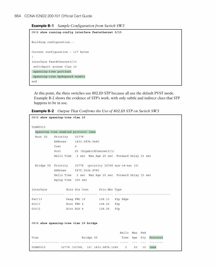
example B-1 Sample Configuration from Switch SW3
SW3# show running-config interface Fastethernet 0/13
Building configuration...
Current configuration : 117 bytes
!
interface FastEthernet0/13
switchport access vlan 10
spanning-tree portfast
spanning-tree bpduguard enable
end
At this point, the three switches use 802.1D STP because all use the default PVST mode. Example B-2 shows the evidence of STP’s work, with only subtle and indirect clues that STP happens to be in use.
example B-2 Output That Confirms the Use of 802.1D STP on Switch SW3
SW3# show spanning-tree vlan 10
VLAN0010
Spanning tree enabled protocol ieee
Root ID Priority 32778
Address 1833.9d7b.0e80
Cost 4
Port 25 (GigabitEthernet0/1)
Hello Time 2 sec Max Age 20 sec Forward Delay 15 sec
Bridge ID Priority 32778 (priority 32768 sys-id-ext 10)
Address f47f.35cb.d780
Hello Time 2 sec Max Age 20 sec Forward Delay 15 sec
Aging Time 300 sec
Interface Role Sts Cost Prio.Nbr Type
------------------- ---- --- --------- -------- --------------------------------
Fa0/13 Desg FWD 19 128.13 P2p Edge
Gi0/1 Root FWD 4 128.25 P2p
Gi0/2 Altn BLK 4 128.26 P2p
SW3# show spanning-tree vlan 10 bridge
Hello Max Fwd
Vlan Bridge ID Time Age Dly Protocol
---------------- --------------------------------- ----- --- --- --------
VLAN0010 32778 (32768, 10) 1833.9d7b.1380 2 20 15 ieee
B
Appendix B: ICND2 Exam Updates 665
The highlighted parts of the example note the references to the STP protocol as ieee, which implies that STP is in use. The term ieee is a reference to the original IEEE 802.1D STP standard.
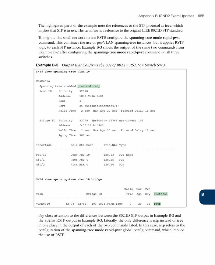
To migrate this small network to use RSTP, configure the spanning-tree mode rapid-pvst command. This continues the use of per-VLAN spanning-tree instances, but it applies RSTP logic to each STP instance. Example B-3 shows the output of the same two commands from Example B-2 after configuring the spanning-tree mode rapid-pvst command on all three switches.
example B-3 Output that Confirms the Use of 802.1w RSTP on Switch SW3
SW3# show spanning-tree vlan 10
VLAN0010
Spanning tree enabled protocol rstp
Root ID Priority 32778
Address 1833.9d7b.0e80
Cost 4
Port 25 (GigabitEthernet0/1)
Hello Time 2 sec Max Age 20 sec Forward Delay 15 sec
Bridge ID Priority 32778 (priority 32768 sys-id-ext 10)
Address f47f.35cb.d780
Hello Time 2 sec Max Age 20 sec Forward Delay 15 sec
Aging Time 300 sec
Interface Role Sts Cost Prio.Nbr Type
------------------- ---- --- --------- -------- --------------------------------
Fa0/13 Desg FWD 19 128.13 P2p Edge
Gi0/1 Root FWD 4 128.25 P2p
Gi0/2 Altn BLK 4 128.26 P2p
SW3# show spanning-tree vlan 10 bridge
Hello Max Fwd
Vlan Bridge ID Time Age Dly Protocol
---------------- --------------------------------- ----- --- --- --------
VLAN0010 32778 (32768, 10) 1833.9d7b.1380 2 20 15 rstp
Pay close attention to the differences between the 802.1D STP output in Example B-2 and the 802.1w RSTP output in Example B-3. Literally, the only difference is rstp instead of ieee in one place in the output of each of the two commands listed. In this case, rstp refers to the configuration of the spanning-tree mode rapid-pvst global config command, which implied the use of RSTP.
666 CCNA ICND2 200-101 Official Cert Guide
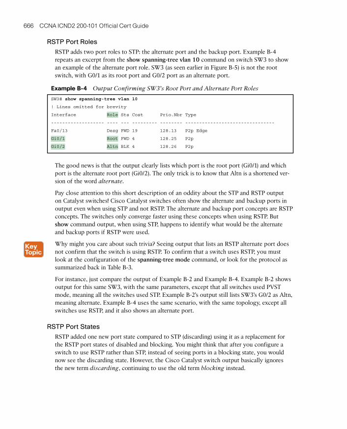
RSTP Port Roles
RSTP adds two port roles to STP: the alternate port and the backup port. Example B-4 repeats an excerpt from the show spanning-tree vlan 10 command on switch SW3 to show an example of the alternate port role. SW3 (as seen earlier in Figure B-5) is not the root switch, with G0/1 as its root port and G0/2 port as an alternate port.
example B-4 Output Confirming SW3’s Root Port and Alternate Port Roles
SW3# show spanning-tree vlan 10
! Lines omitted for brevity
Interface Role Sts Cost Prio.Nbr Type
------------------- ---- --- --------- -------- --------------------------------
Fa0/13 Desg FWD 19 128.13 P2p Edge
Gi0/1 Root FWD 4 128.25 P2p
Gi0/2 Altn BLK 4 128.26 P2p
The good news is that the output clearly lists which port is the root port (Gi0/1) and which port is the alternate root port (Gi0/2). The only trick is to know that Altn is a shortened ver-sion of the word alternate.
Pay close attention to this short description of an oddity about the STP and RSTP output on Catalyst switches! Cisco Catalyst switches often show the alternate and backup ports in output even when using STP and not RSTP. The alternate and backup port concepts are RSTP concepts. The switches only converge faster using these concepts when using RSTP. But show command output, when using STP, happens to identify what would be the alternate and backup ports if RSTP were used.
Why might you care about such trivia? Seeing output that lists an RSTP alternate port does not confirm that the switch is using RSTP. To confirm that a switch uses RSTP, you must look at the configuration of the spanning-tree mode command, or look for the protocol as summarized back in Table B-3.
For instance, just compare the output of Example B-2 and Example B-4. Example B-2 shows output for this same SW3, with the same parameters, except that all switches used PVST mode, meaning all the switches used STP. Example B-2’s output still lists SW3’s G0/2 as Altn, meaning alternate. Example B-4 uses the same scenario, with the same topology, except all switches use RSTP, and it also shows an alternate port.
RSTP Port States
RSTP added one new port state compared to STP (discarding) using it as a replacement for the RSTP port states of disabled and blocking. You might think that after you configure a switch to use RSTP rather than STP, instead of seeing ports in a blocking state, you would now see the discarding state. However, the Cisco Catalyst switch output basically ignores the new term discarding, continuing to use the old term blocking instead.
B
Appendix B: ICND2 Exam Updates 667
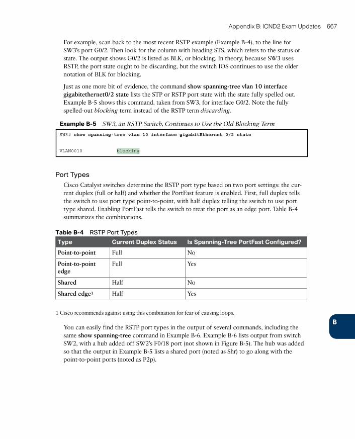
For example, scan back to the most recent RSTP example (Example B-4), to the line for SW3’s port G0/2. Then look for the column with heading STS, which refers to the status or state. The output shows G0/2 is listed as BLK, or blocking. In theory, because SW3 uses RSTP, the port state ought to be discarding, but the switch IOS continues to use the older notation of BLK for blocking.
Just as one more bit of evidence, the command show spanning-tree vlan 10 interface gigabitethernet0/2 state lists the STP or RSTP port state with the state fully spelled out. Example B-5 shows this command, taken from SW3, for interface G0/2. Note the fully spelled-out blocking term instead of the RSTP term discarding.
example B-5 SW3, an RSTP Switch, Continues to Use the Old Blocking Term
SW3# show spanning-tree vlan 10 interface gigabitEthernet 0/2 state
VLAN0010 blocking
Port Types
Cisco Catalyst switches determine the RSTP port type based on two port settings: the cur-rent duplex (full or half) and whether the PortFast feature is enabled. First, full duplex tells the switch to use port type point-to-point, with half duplex telling the switch to use port type shared. Enabling PortFast tells the switch to treat the port as an edge port. Table B-4 summarizes the combinations.
Table B-4 RSTP Port Types
Type Current duplex Status is Spanning-Tree portFast Configured?
Point-to-point Full No
Point-to-point edge
Full Yes
Shared Half No
Shared edge1 Half Yes
1 Cisco recommends against using this combination for fear of causing loops.
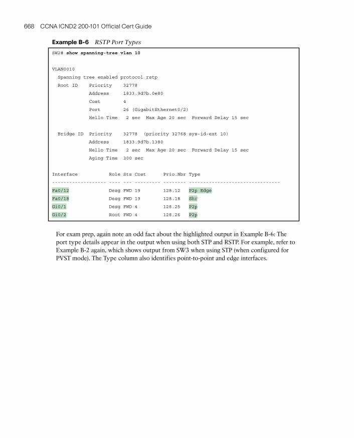
You can easily find the RSTP port types in the output of several commands, including the same show spanning-tree command in Example B-6. Example B-6 lists output from switch SW2, with a hub added off SW2’s F0/18 port (not shown in Figure B-5). The hub was added so that the output in Example B-5 lists a shared port (noted as Shr) to go along with the point-to-point ports (noted as P2p).
668 CCNA ICND2 200-101 Official Cert Guide
example B-6 RSTP Port Types
SW2# show spanning-tree vlan 10
VLAN0010
Spanning tree enabled protocol rstp
Root ID Priority 32778
Address 1833.9d7b.0e80
Cost 4
Port 26 (GigabitEthernet0/2)
Hello Time 2 sec Max Age 20 sec Forward Delay 15 sec
Bridge ID Priority 32778 (priority 32768 sys-id-ext 10)
Address 1833.9d7b.1380
Hello Time 2 sec Max Age 20 sec Forward Delay 15 sec
Aging Time 300 sec
Interface Role Sts Cost Prio.Nbr Type
------------------- ---- --- --------- -------- --------------------------------
Fa0/12 Desg FWD 19 128.12 P2p Edge
Fa0/18 Desg FWD 19 128.18 Shr
Gi0/1 Desg FWD 4 128.25 P2p
Gi0/2 Root FWD 4 128.26 P2p
For exam prep, again note an odd fact about the highlighted output in Example B-6: The port type details appear in the output when using both STP and RSTP. For example, refer to Example B-2 again, which shows output from SW3 when using STP (when configured for PVST mode). The Type column also identifies point-to-point and edge interfaces.