ICEM PlotServer Package Version 4 - Dassault...
117
ICEM PlotServer Package Version 4.1 User and Administrator Manual April 2003 © ICEM Ltd. 2003
Transcript of ICEM PlotServer Package Version 4 - Dassault...
ICEM PlotServer Package
Version 4.1
User and Administrator Manual
April 2003
© ICEM Ltd. 2003

Legal Notices and Contact
Copyright Information
Copyright © 2003 ICEM Ltd. All Rights Reserved.
User and training documentation from ICEM is subject to the copyright laws of the United States and other countries and is provided under a license agreement that restricts copying, disclosure, and use of such documentation. ICEM hereby grants to the licensed user the right to make such limited copies in printed form of this documentation if provided on software media, as may be necessary for internal/personal use only and all such copies shall be made in accordance with the license agreement under which the applicable software is licensed to the licensed user. Any copy made shall include the full ICEM copyright notice and any other proprietary notice provided by ICEM to the licensed user from time to time. This documentation may not be disclosed, transferred, modified, or reduced to any form, including, but not limited to, electronic media, or transmitted or made publicly available by any means whatsoever without the prior written consent of ICEM and no authorization is granted to make copies for such purposes.
Information described herein is furnished for general information only, is subject to change without notice, and should not, in any circumstances, be construed as a warranty or commitment by ICEM. ICEM assumes nor accepts any responsibility or liability for any errors or inaccuracies howsoever arising that may appear in this document.
The software described in this document is provided under a written license agreement, contains valuable trade secrets and commercial and intellectual proprietary information, and is protected by the copyright laws of the United States and other countries. It may not be copied or distributed in any form or medium, disclosed to third parties, or used in any manner not provided for in the software licenses agreement except with written prior approval from ICEM. PLEASE NOTE THAT UNAUTHORIZED USE OF SOFTWARE OR ITS DOCUMENTATION CAN RESULT IN CIVIL DAMAGES AND CRIMINAL PROSECUTION.
Registered Trade Marks of ICEM Ltd. or a Subsidiary
ICEM is a registered trade mark of ICEM Ltd.
Trade marks of ICEM Ltd. or a Subsidiary
ICEM Surf and ICEM DDN are unregistered trade marks of ICEM Ltd.
Third-Party Trade Marks
Adobe is a registered trade mark of Adobe Systems. AIX is a trade mark or registered trade mark of International Business Machines Corporation in the United States and other countries. CATIA is a registered trade mark of Dassault Systems. HP-UX is a registered trade mark of the Hewlett-Packard Company. I-DEAS is a trade mark or registered trade mark of Electronic Data Systems Corporation (EDS). InstallShield is a registered trade mark and service mark of InstallShield Software Corporation in the United States and/or other countries. IRIX is a registered trade mark of Silicon Graphics, Inc. Sun Solaris is a trade mark or registered trade mark of Sun Microsystems. Microsoft, Windows, Windows NT, Visual Basic, and the Visual Basic logo are registered trade marks of Microsoft Corporation in the United States and/or other countries. SuSE and its logo are registered trade marks of SuSE AG. Red Hat, the Red Hat "Shadow Man" logo, RPM, Maximum RPM, the RPM logo, Linux Library, PowerTools, Linux Undercover, RHmember, RHmember More, Rough Cuts, Rawhide and all Red Hat-based trade marks and logos are trade marks or registered trade marks of Red Hat, Inc. in the United States and other countries. Linux is a registered trade mark of Linus Torvald.
Licensed Third-Party Technology Information
Certain ICEM software products contain licensed third-party technology: FLEXlm is a registered trade mark of Macrovision Corporation. LightWork Libraries are copyrighted by LightWork Design 1990-2003. Pro/ENGINEER, CDRS, 3DPAINT are copyrighted by Parametric Technology Corporation. The CADverter for Catia, Cadds, Unigraphics are copyrighted by Theorem Solutions Ltd.
UNITED STATES GOVERNMENT RESTRICTED RIGHTS LEGEND
This document and the software described herein are Commercial Computer Documentation and Software, pursuant to FAR 12.212(a)-(b) (OCT'95) or DFARS 227.7202-1(a) and 227.7202-3(a) (JUN'95), is provided to the US Government under a limited commercial license only. For procurements predating the above clauses, use, duplication, or disclosure by the Government is subject to the restrictions set forth in subparagraph (c)(1)(ii) of the Rights in Technical Data and Computer Software Clause at DFARS 252.227-7013 (OCT'88) or Commercial Computer Software-Restricted Rights at FAR 52.227-19(c)(1)-(2) (JUN'87) or FAR 52.227-14 (ALT III), as applicable. 032603
ICEM Ltd.: registered office: Epsilon House, Enterprise Road, Chilworth Science Park, Southampton, SO16 7NS, U.K.

Contact Information
Licenses
Hotline
in Europe:
ICEM Technologies GmbHSiemensstrasse 963263 Neu-IsenburgGermany
Phone:Fax:E-mail:
+49 (0) 6102 366 9090+49 (0) 6102 366 [email protected]
outside Europe:
ICEM Technologies, Inc.38705 Seven Mile RoadSuite 320 Livonia, MI 48152USA
Phone: USA & Canada:outside USA:
+1 800 692 7322+1 734 462 1795
Fax:E-mail:
+1 734 462 [email protected]
Sales
in Europe:
ICEM Technologies GmbHSiemensstrasse 963263 Neu-IsenburgGermany
Phone:Fax:E-mail:
+49 6102 366 9000+49 6102 366 [email protected]
outside Europe:
ICEM Technologies, Inc.38705 Seven Mile RoadSuite 320 Livonia, MI 48152USA
Phone:Fax:E-mail:
+1 734 462 1795+1 734 462 [email protected]

Contents
Contents
Chapter 0 About this Manual 0-1
0.1 Manual Organization . . . . . . . . . . . . . . . . . . . . . . . . . . . . . . . . . . . . . . . . . . . . . . . . . . . . . . . . . . . . . . . . . . . . 0-1
0.2 Manual History . . . . . . . . . . . . . . . . . . . . . . . . . . . . . . . . . . . . . . . . . . . . . . . . . . . . . . . . . . . . . . . . . . . . . . . . 0-1
0.3 Conventions . . . . . . . . . . . . . . . . . . . . . . . . . . . . . . . . . . . . . . . . . . . . . . . . . . . . . . . . . . . . . . . . . . . . . . . . . . . 0-2
0.4 Customer Support (Hotline) . . . . . . . . . . . . . . . . . . . . . . . . . . . . . . . . . . . . . . . . . . . . . . . . . . . . . . . . . . . . . . 0-3
0.5 Sales. . . . . . . . . . . . . . . . . . . . . . . . . . . . . . . . . . . . . . . . . . . . . . . . . . . . . . . . . . . . . . . . . . . . . . . . . . . . . . . . . 0-3
0.6 ICEM License Files . . . . . . . . . . . . . . . . . . . . . . . . . . . . . . . . . . . . . . . . . . . . . . . . . . . . . . . . . . . . . . . . . . . . . 0-4
0.7 More Information . . . . . . . . . . . . . . . . . . . . . . . . . . . . . . . . . . . . . . . . . . . . . . . . . . . . . . . . . . . . . . . . . . . . . . 0-4
Chapter 1 Introduction 1-1
1.1 Supported Operating Systems . . . . . . . . . . . . . . . . . . . . . . . . . . . . . . . . . . . . . . . . . . . . . . . . . . . . . . . . . . . . . 1-1
1.2 Structure of this manual. . . . . . . . . . . . . . . . . . . . . . . . . . . . . . . . . . . . . . . . . . . . . . . . . . . . . . . . . . . . . . . . . . 1-1
1.3 Plot Scenario and Purpose of the PlotServer Package. . . . . . . . . . . . . . . . . . . . . . . . . . . . . . . . . . . . . . . . . . . 1-1
Chapter 2 The Icem PlotServer Concept 2-1
Chapter 3 Identifying and Using Defined Plotters 3-1
3.1 Identifying and Using Plotters on the System Level (UNIX Shell) . . . . . . . . . . . . . . . . . . . . . . . . . . . . . . . . 3-1
3.1.1 Identifying Plotters and Making Status Queries . . . . . . . . . . . . . . . . . . . . . . . . . . . . . . . . . . . . . . . . 3-1
3.1.2 Using Plotters . . . . . . . . . . . . . . . . . . . . . . . . . . . . . . . . . . . . . . . . . . . . . . . . . . . . . . . . . . . . . . . . . . 3-2
3.1.3 Managing Printing and Plotting Jobs . . . . . . . . . . . . . . . . . . . . . . . . . . . . . . . . . . . . . . . . . . . . . . . . 3-4
3.2 Identifying and Using Plotters under the ICEMview User Interface . . . . . . . . . . . . . . . . . . . . . . . . . . . . . . . 3-4
3.3 Plotting from Inside an ICEM Application . . . . . . . . . . . . . . . . . . . . . . . . . . . . . . . . . . . . . . . . . . . . . . . . . . . 3-8
3.3.1 ICEM DDN. . . . . . . . . . . . . . . . . . . . . . . . . . . . . . . . . . . . . . . . . . . . . . . . . . . . . . . . . . . . . . . . . . . . 3-8
3.3.2 ICEM Surf . . . . . . . . . . . . . . . . . . . . . . . . . . . . . . . . . . . . . . . . . . . . . . . . . . . . . . . . . . . . . . . . . . . 3-11
3.3.3 Icem Duct . . . . . . . . . . . . . . . . . . . . . . . . . . . . . . . . . . . . . . . . . . . . . . . . . . . . . . . . . . . . . . . . . . . . 3-12
Chapter 4 Installing the ICEM PlotServer Package 4-1
4.1 Preparing Installation from Cartridge. . . . . . . . . . . . . . . . . . . . . . . . . . . . . . . . . . . . . . . . . . . . . . . . . . . . . . . 4-1
4.2 Preparing Installation from CD-ROM. . . . . . . . . . . . . . . . . . . . . . . . . . . . . . . . . . . . . . . . . . . . . . . . . . . . . . . 4-2
4.3 Installation with the ICEM Installer . . . . . . . . . . . . . . . . . . . . . . . . . . . . . . . . . . . . . . . . . . . . . . . . . . . . . . . . 4-3
4.4 Installation with the PTC.Setup Program . . . . . . . . . . . . . . . . . . . . . . . . . . . . . . . . . . . . . . . . . . . . . . . . . . . . 4-5
4.5 Licensing . . . . . . . . . . . . . . . . . . . . . . . . . . . . . . . . . . . . . . . . . . . . . . . . . . . . . . . . . . . . . . . . . . . . . . . . . . . . . 4-7
4.6 Deinstalling the ICEM PlotServer Package . . . . . . . . . . . . . . . . . . . . . . . . . . . . . . . . . . . . . . . . . . . . . . . . . . 4-7
Chapter 5 Creating a Plot Queue on the Plot Server 5-1
5.1 Creating a Plot Queue Using IRIX System Commands . . . . . . . . . . . . . . . . . . . . . . . . . . . . . . . . . . . . . . . . . 5-1
5.2 Creating a Plot Queue Using the IRIX Printer Manager . . . . . . . . . . . . . . . . . . . . . . . . . . . . . . . . . . . . . . . . . 5-2
1
Contents
Chapter 6 Testing a Plot Queue on the Plot Server 6-1
Chapter 7 Creating a Plot Queue on the Plot Client 7-1
7.1 Creating a Network Plot Queue Using IRIX System Commands . . . . . . . . . . . . . . . . . . . . . . . . . . . . . . . . . .7-1
7.2 Creating a Network Plot Queue Using the IRIX Printer Manager . . . . . . . . . . . . . . . . . . . . . . . . . . . . . . . . . .7-1
Chapter 8 Removing a Plot Queue 8-1
8.1 Removing a Plot Queue Using IRIX System Commands . . . . . . . . . . . . . . . . . . . . . . . . . . . . . . . . . . . . . . . .8-1
8.2 Removing a Plot Queue Using the IRIX Printer Manager . . . . . . . . . . . . . . . . . . . . . . . . . . . . . . . . . . . . . . . .8-1
Chapter 9 Customizing the Plot Server 9-1
9.1 Customizing the Access Path of the License File. . . . . . . . . . . . . . . . . . . . . . . . . . . . . . . . . . . . . . . . . . . . . . .9-4
9.2 Entering the Uniplot Postprocessor and Keyword . . . . . . . . . . . . . . . . . . . . . . . . . . . . . . . . . . . . . . . . . . . . . .9-4
9.3 Entering and Changing a Start and End Sequence . . . . . . . . . . . . . . . . . . . . . . . . . . . . . . . . . . . . . . . . . . . . . .9-6
9.4 Changing the Default Uniplot Directives . . . . . . . . . . . . . . . . . . . . . . . . . . . . . . . . . . . . . . . . . . . . . . . . . . . . .9-8
9.5 Entering and Processing New Options . . . . . . . . . . . . . . . . . . . . . . . . . . . . . . . . . . . . . . . . . . . . . . . . . . . . . . .9-8
9.6 Further Processing of Plot Files Created on the Hard Disk . . . . . . . . . . . . . . . . . . . . . . . . . . . . . . . . . . . . . .9-10
9.6.1 Manipulating Plot Files . . . . . . . . . . . . . . . . . . . . . . . . . . . . . . . . . . . . . . . . . . . . . . . . . . . . . . . . . .9-10
9.6.2 Transferring Plot Files to the BSD Spooling System . . . . . . . . . . . . . . . . . . . . . . . . . . . . . . . . . . .9-10
9.6.3 Sending Plot Files to an Output Device Connected via Ethernet. . . . . . . . . . . . . . . . . . . . . . . . . . .9-12
9.6.4 Transferring Plot Files in Other Ways . . . . . . . . . . . . . . . . . . . . . . . . . . . . . . . . . . . . . . . . . . . . . . .9-12
9.7 Customizations to the Uniplot Postprocessors . . . . . . . . . . . . . . . . . . . . . . . . . . . . . . . . . . . . . . . . . . . . . . . .9-12
9.7.1 Making Changes in the File DHCFILE . . . . . . . . . . . . . . . . . . . . . . . . . . . . . . . . . . . . . . . . . . . . . .9-13
9.7.2 Making Changes in the File DHCEXT . . . . . . . . . . . . . . . . . . . . . . . . . . . . . . . . . . . . . . . . . . . . . .9-14
Chapter 10 Diagnosing and Correcting Plotting Problems 10-1
10.1 The Log File ‘plotlog’ on the Plot Server. . . . . . . . . . . . . . . . . . . . . . . . . . . . . . . . . . . . . . . . . . . . . . . . . . . .10-1
10.2 The Diagnostic Script ‘tst_plotter’ on the Plot Server . . . . . . . . . . . . . . . . . . . . . . . . . . . . . . . . . . . . . . . . . .10-3
10.3 Restarting the LP Spooler without Rebooting . . . . . . . . . . . . . . . . . . . . . . . . . . . . . . . . . . . . . . . . . . . . . . . .10-3
Chapter 11 Information on Output Devices and the Uniplot Software 11-1
11.1 Notes on the Operation of the PlotServer Package on AIX . . . . . . . . . . . . . . . . . . . . . . . . . . . . . . . . . . . . . .11-1
11.2 Notes on the Operation of CalComp CAL907 Output Devices . . . . . . . . . . . . . . . . . . . . . . . . . . . . . . . . . . .11-4
11.2.1 Pen Plotters . . . . . . . . . . . . . . . . . . . . . . . . . . . . . . . . . . . . . . . . . . . . . . . . . . . . . . . . . . . . . . . . . . .11-5
11.2.2 Raster Plotters (Laser, Ink Jet, Thermal, Electrostatic) . . . . . . . . . . . . . . . . . . . . . . . . . . . . . . . . . .11-6
11.2.3 Using CDCL (CalComp Device Control Language) . . . . . . . . . . . . . . . . . . . . . . . . . . . . . . . . . . . .11-6
11.3 Notes on the Operation of HPGL and HPGL/2 Output Devices . . . . . . . . . . . . . . . . . . . . . . . . . . . . . . . . . .11-7
11.3.1 DIN A4/A3 Printers (Laser, Ink Jet) . . . . . . . . . . . . . . . . . . . . . . . . . . . . . . . . . . . . . . . . . . . . . . .11-10
11.3.2 HP75XX Series Pen Plotters . . . . . . . . . . . . . . . . . . . . . . . . . . . . . . . . . . . . . . . . . . . . . . . . . . . . .11-10
11.3.3 DesignJet Series Raster Plotters. . . . . . . . . . . . . . . . . . . . . . . . . . . . . . . . . . . . . . . . . . . . . . . . . . .11-10
2
Contents
11.4 Notes on the Operation of PostScript Output Devices . . . . . . . . . . . . . . . . . . . . . . . . . . . . . . . . . . . . . . . . 11-13
11.4.1 troke Widths . . . . . . . . . . . . . . . . . . . . . . . . . . . . . . . . . . . . . . . . . . . . . . . . . . . . . . . . . . . . . . . . . 11-13
11.4.2 DIN A4/A3 Laser Printers . . . . . . . . . . . . . . . . . . . . . . . . . . . . . . . . . . . . . . . . . . . . . . . . . . . . . . 11-14
11.5 Supporting Other Output Devices . . . . . . . . . . . . . . . . . . . . . . . . . . . . . . . . . . . . . . . . . . . . . . . . . . . . . . . . 11-15
11.6 Manual Use of the Uniplot Preprocessors and Postprocessors . . . . . . . . . . . . . . . . . . . . . . . . . . . . . . . . . . 11-16
11.7 Notes about Uniplot Version 3.3 Release 01. . . . . . . . . . . . . . . . . . . . . . . . . . . . . . . . . . . . . . . . . . . . . . . . 11-18
11.7.1 The Uniplot Postprocessors and their Keywords . . . . . . . . . . . . . . . . . . . . . . . . . . . . . . . . . . . . . 11-18
11.8 The LP Spooler Interface File ‘plotface2.1’ . . . . . . . . . . . . . . . . . . . . . . . . . . . . . . . . . . . . . . . . . . . . . . . . 11-21
11.8.1 Innovations and Changes in ‘plotface2.1’ . . . . . . . . . . . . . . . . . . . . . . . . . . . . . . . . . . . . . . . . . . 11-21
11.8.2 Listing of the LP Spooler Interface File ‘plotface2.1’ . . . . . . . . . . . . . . . . . . . . . . . . . . . . . . . . . 11-22
3

Contents
4
Figures
Figures
Figure 1 Heterogeneous plotting environment . . . . . . . . . . . . . . . . . . . . . . . . . . . . . . . . . . . . . . . . . . . . . . . . . . . 1-2
Figure 2 LP spooler integrated plot format creation. . . . . . . . . . . . . . . . . . . . . . . . . . . . . . . . . . . . . . . . . . . . . . . 1-3
Figure 3 Client/Server Principle . . . . . . . . . . . . . . . . . . . . . . . . . . . . . . . . . . . . . . . . . . . . . . . . . . . . . . . . . . . . . . 2-1
Figure 4 Output on the screen of the ‘lpstat -t’ command . . . . . . . . . . . . . . . . . . . . . . . . . . . . . . . . . . . . . . . . . . 3-1
Figure 5 ICEM view Icon Catalog page . . . . . . . . . . . . . . . . . . . . . . . . . . . . . . . . . . . . . . . . . . . . . . . . . . . . . . . . 3-4
Figure 6 ICEM view printer and plotter icons . . . . . . . . . . . . . . . . . . . . . . . . . . . . . . . . . . . . . . . . . . . . . . . . . . . 3-5
Figure 7 ICEM view plotter dialog box . . . . . . . . . . . . . . . . . . . . . . . . . . . . . . . . . . . . . . . . . . . . . . . . . . . . . . . . 3-5
Figure 8 ICEM view printer dialog box . . . . . . . . . . . . . . . . . . . . . . . . . . . . . . . . . . . . . . . . . . . . . . . . . . . . . . . . 3-6
Figure 9 The IRIX 5.x Toolchest menu bar . . . . . . . . . . . . . . . . . . . . . . . . . . . . . . . . . . . . . . . . . . . . . . . . . . . . . 3-6
Figure 10 IRIX Printer Manager. . . . . . . . . . . . . . . . . . . . . . . . . . . . . . . . . . . . . . . . . . . . . . . . . . . . . . . . . . . . . . . 3-7
Figure 11 IRIX Printer Status Panel . . . . . . . . . . . . . . . . . . . . . . . . . . . . . . . . . . . . . . . . . . . . . . . . . . . . . . . . . . . . 3-7
Figure 12 Orga Autoplot DDN menu definitions, etc. . . . . . . . . . . . . . . . . . . . . . . . . . . . . . . . . . . . . . . . . . . . . . . 3-9
Figure 13 Orga Autoplot DDN trace definition, etc. . . . . . . . . . . . . . . . . . . . . . . . . . . . . . . . . . . . . . . . . . . . . . . 3-10
Figure 14 Orga autoplot procedure definition . . . . . . . . . . . . . . . . . . . . . . . . . . . . . . . . . . . . . . . . . . . . . . . . . . . 3-11
Figure 15 Surf Plotter Configuration File. . . . . . . . . . . . . . . . . . . . . . . . . . . . . . . . . . . . . . . . . . . . . . . . . . . . . . . 3-12
Figure 16 ICEM Installer Media-Path input dialog box . . . . . . . . . . . . . . . . . . . . . . . . . . . . . . . . . . . . . . . . . . . . . 4-3
Figure 17 ICEM Installer main dialog box . . . . . . . . . . . . . . . . . . . . . . . . . . . . . . . . . . . . . . . . . . . . . . . . . . . . . . . 4-4
Figure 18 ICEM PlotServer Package directory structure . . . . . . . . . . . . . . . . . . . . . . . . . . . . . . . . . . . . . . . . . . . . 4-4
Figure 19 Main Window of the PTC.Setup Program . . . . . . . . . . . . . . . . . . . . . . . . . . . . . . . . . . . . . . . . . . . . . . . 4-6
Figure 20 IRIX Printer Manager. . . . . . . . . . . . . . . . . . . . . . . . . . . . . . . . . . . . . . . . . . . . . . . . . . . . . . . . . . . . . . . 5-3
Figure 21 IRIX 6.5 Printer Manager Add dialog box with local Connection type selected. . . . . . . . . . . . . . . . . . 5-4
Figure 22 Test plot ‘ddnplot’ . . . . . . . . . . . . . . . . . . . . . . . . . . . . . . . . . . . . . . . . . . . . . . . . . . . . . . . . . . . . . . . . . 6-1
Figure 23 Diagnostic script ‘tst_plotter’ . . . . . . . . . . . . . . . . . . . . . . . . . . . . . . . . . . . . . . . . . . . . . . . . . . . . . . . . . 6-2
Figure 24 Diagnostic script — phase 1. . . . . . . . . . . . . . . . . . . . . . . . . . . . . . . . . . . . . . . . . . . . . . . . . . . . . . . . . . 6-3
Figure 25 Diagnostic script — phase 2. . . . . . . . . . . . . . . . . . . . . . . . . . . . . . . . . . . . . . . . . . . . . . . . . . . . . . . . . . 6-3
Figure 26 Diagnostic script — phase 3. . . . . . . . . . . . . . . . . . . . . . . . . . . . . . . . . . . . . . . . . . . . . . . . . . . . . . . . . . 6-3
Figure 27 Diagnostic script — phase 4. . . . . . . . . . . . . . . . . . . . . . . . . . . . . . . . . . . . . . . . . . . . . . . . . . . . . . . . . . 6-3
Figure 28 Diagnostic script — display of the log file. . . . . . . . . . . . . . . . . . . . . . . . . . . . . . . . . . . . . . . . . . . . . . . 6-4
Figure 29 Diagnostic script — phase 5. . . . . . . . . . . . . . . . . . . . . . . . . . . . . . . . . . . . . . . . . . . . . . . . . . . . . . . . . . 6-4
Figure 30 IRIX Printer Manager Add dialog box with Network Connection Type selected . . . . . . . . . . . . . . . . . 7-2
Figure 31 IRIX Printer Manager Delete dialog box . . . . . . . . . . . . . . . . . . . . . . . . . . . . . . . . . . . . . . . . . . . . . . . . 8-1
Figure 32 Structure of the interface file ‘plotface’ . . . . . . . . . . . . . . . . . . . . . . . . . . . . . . . . . . . . . . . . . . . . . . . . 9-2
Figure 33 Section of the customizing area of the file ‘plotface2.1’ (to be continued) . . . . . . . . . . . . . . . . . . . . . . 9-3
Figure 34 Section of the customizing area of the file ’plotface2.1’ (continued) . . . . . . . . . . . . . . . . . . . . . . . . . . 9-4
Figure 35 Selection of the Uniplot postprocessor. . . . . . . . . . . . . . . . . . . . . . . . . . . . . . . . . . . . . . . . . . . . . . . . . . 9-5
Figure 36 Selection of the Uniplot keyword. . . . . . . . . . . . . . . . . . . . . . . . . . . . . . . . . . . . . . . . . . . . . . . . . . . . . . 9-6
Figure 37 Definition of a start/end sequence . . . . . . . . . . . . . . . . . . . . . . . . . . . . . . . . . . . . . . . . . . . . . . . . . . . . . 9-7
5
Figures
Figure 38 Uniplot standard directive(s) . . . . . . . . . . . . . . . . . . . . . . . . . . . . . . . . . . . . . . . . . . . . . . . . . . . . . . . . . .9-8
Figure 39 ‘plotface’ options . . . . . . . . . . . . . . . . . . . . . . . . . . . . . . . . . . . . . . . . . . . . . . . . . . . . . . . . . . . . . . . . . . .9-9
Figure 40 Processing of the ready-to-plot file 'PLOTF' . . . . . . . . . . . . . . . . . . . . . . . . . . . . . . . . . . . . . . . . . . . . .9-10
Figure 41 Example of a remote BSD queue entry in the /etc/printcap file . . . . . . . . . . . . . . . . . . . . . . . . . . . . . .9-11
Figure 42 Example of a local BSD queue entry in the /etc/printcap file . . . . . . . . . . . . . . . . . . . . . . . . . . . . . . . .9-12
Figure 43 The 'dhcutl' program . . . . . . . . . . . . . . . . . . . . . . . . . . . . . . . . . . . . . . . . . . . . . . . . . . . . . . . . . . . . . . .9-13
Figure 44 Excerpt of the file 'DHCEXT' (to be continued) . . . . . . . . . . . . . . . . . . . . . . . . . . . . . . . . . . . . . . . . . .9-15
Figure 45 Excerpt of the file ’DHCEXT’ (continued) . . . . . . . . . . . . . . . . . . . . . . . . . . . . . . . . . . . . . . . . . . . . . .9-16
Figure 46 Log file ‘plotlog’. . . . . . . . . . . . . . . . . . . . . . . . . . . . . . . . . . . . . . . . . . . . . . . . . . . . . . . . . . . . . . . . . .10-2
Figure 47 Section of the customizing area of the file 'pll' . . . . . . . . . . . . . . . . . . . . . . . . . . . . . . . . . . . . . . . . . . .11-2
Figure 48 Customizing area of the file 'plr' . . . . . . . . . . . . . . . . . . . . . . . . . . . . . . . . . . . . . . . . . . . . . . . . . . . . . .11-3
Figure 49 Customizing plot file handling in the file ‘pll‘ . . . . . . . . . . . . . . . . . . . . . . . . . . . . . . . . . . . . . . . . . . .11-3
Figure 50 'Plotface2.1 CAL907’ customizing area . . . . . . . . . . . . . . . . . . . . . . . . . . . . . . . . . . . . . . . . . . . . . . . .11-4
Figure 51 Example of the use of CDCL commands . . . . . . . . . . . . . . . . . . . . . . . . . . . . . . . . . . . . . . . . . . . . . . .11-6
Figure 52 HPGL P1/P2 corners . . . . . . . . . . . . . . . . . . . . . . . . . . . . . . . . . . . . . . . . . . . . . . . . . . . . . . . . . . . . . . .11-7
Figure 53 Customizing area for ‘Plotface 2.1 HPGL’ . . . . . . . . . . . . . . . . . . . . . . . . . . . . . . . . . . . . . . . . . . . . . .11-8
Figure 54 Customizing area for ‘Plotface 2.1 HPGL/2’ . . . . . . . . . . . . . . . . . . . . . . . . . . . . . . . . . . . . . . . . . . . .11-9
Figure 55 Definition of pen attributes in the ‘DHCEXT’ file. . . . . . . . . . . . . . . . . . . . . . . . . . . . . . . . . . . . . . .11-12
Figure 56 Customizing area for ‘Plotface 2.1 PostScript’ . . . . . . . . . . . . . . . . . . . . . . . . . . . . . . . . . . . . . . . . . .11-13
Figure 57 Customizing stroke width in a PostScript file . . . . . . . . . . . . . . . . . . . . . . . . . . . . . . . . . . . . . . . . . . .11-14
Figure 58 Incorporation of paper tray selection into the PostScript file 'PLOTF' . . . . . . . . . . . . . . . . . . . . . . . .11-15
Figure 59 Running the Uniplot postprocessor manually . . . . . . . . . . . . . . . . . . . . . . . . . . . . . . . . . . . . . . . . . . .11-17
6
Tables
Tables
Table 1 Standard Uniplot CAL907 parameters . . . . . . . . . . . . . . . . . . . . . . . . . . . . . . . . . . . . . . . . . . . . . . . . . . 11-4
Table 2 Uniplot CAL907 transmission parameters . . . . . . . . . . . . . . . . . . . . . . . . . . . . . . . . . . . . . . . . . . . . . . . 11-5
Table 3 Uniplot HPGLR/HPGLU transmission parameters. . . . . . . . . . . . . . . . . . . . . . . . . . . . . . . . . . . . . . . . . 11-9
Table 4 DesignJet settings . . . . . . . . . . . . . . . . . . . . . . . . . . . . . . . . . . . . . . . . . . . . . . . . . . . . . . . . . . . . . . . . . 11-11
Table 5 Optimization parameters of the ‘optim‘ program . . . . . . . . . . . . . . . . . . . . . . . . . . . . . . . . . . . . . . . . . 11-16
Table 6 The most important Uniplot directives . . . . . . . . . . . . . . . . . . . . . . . . . . . . . . . . . . . . . . . . . . . . . . . . . 11-18
Table 7 CAL907 Keywords . . . . . . . . . . . . . . . . . . . . . . . . . . . . . . . . . . . . . . . . . . . . . . . . . . . . . . . . . . . . . . . . 11-18
Table 8 CALPM Keywords . . . . . . . . . . . . . . . . . . . . . . . . . . . . . . . . . . . . . . . . . . . . . . . . . . . . . . . . . . . . . . . . 11-19
Table 9 HPGLR Keywords. . . . . . . . . . . . . . . . . . . . . . . . . . . . . . . . . . . . . . . . . . . . . . . . . . . . . . . . . . . . . . . . . 11-20
Table 10 HPGLU Keywords. . . . . . . . . . . . . . . . . . . . . . . . . . . . . . . . . . . . . . . . . . . . . . . . . . . . . . . . . . . . . . . . . 11-20
Table 11 POSTSC Keywords . . . . . . . . . . . . . . . . . . . . . . . . . . . . . . . . . . . . . . . . . . . . . . . . . . . . . . . . . . . . . . . . 11-21
7

Tables
8

Chapter 0 About this Manual
Chapter 0 About this Manual
This manual is one of a set of manuals that describe the ICEM DDN software system. ICEM stands for Integrated
Computer-Aided Engineering and Manufacturing, DDN stands for Design/Drafting/Numerical Control.
ICEM DDN is a computer-aided design/computer-aided manufacturing (CAD/CAM) software package for 3-D
design, solid modeling, ANSI and DIN drafting, and numerically controlled manufacturing. It is an open system that
supports data exchange with other CAD/CAM systems.
This is a manual for design engineers and drafting personnel who have had initial training in the use of the ICEM sys-
tem. It is not intended to be a tutorial guide. For a step-by-step introduction to the ICEM system, refer to the ICEM
DDN Tutorial.
0.1 Manual Organization
This manual is organized as follows:
0.2 Manual History
The ICEM DDN 5.0 release does not contain any changes.
This edition obsoletes all previous editions.1
Chapter Description
1 Contains an introduction to the ICEM PlotServer Package.
2 Explains the ICEM PlotServer concept.
3 Shows how to identify and use defined plotters.
4 Describes the Installation of the ICEM PlotServer Package.
5 Shows how to create a plot queue on the plot server.
6 Shows how to test a plot queue on the plot server.
7 Shows how to create a plot queue on the plot client.
8 Shows how to remove a plot queue.
9 Describes how to customize the plot server.
10 Helps to diagnose and correct printing problems.
11 Introduces several output devices and gives additional information on operating system dependencies and the Uni-plot software.
1. © 1987, 1989, 1991, 1992, 1993, 1994, 1995, 1996, 1997, 1998, 1999, 2000 by ICEM TechnologiesAll rights reserved.
0-1

0.3 Conventions
0.3 Conventions
The following conventions are used in the manuals:
• Menus are represented by a series of numbers separated by periods. These numbers, called menu strings, represent
the selections in the ICEM DDN menu hierarchy. The first number is the main menu choice, the second number is
the second-level menu choice, and so on. For example, menu choice 5.13.3 EXECUTE A GPL PROGRAM is the
third level of the menu hierarchy.
Entering F or CTRL-F at any ICEM DDN menu or prompt returns you to the main menu. In the manuals, an “F.”
or “f.” is sometimes shown before a menu string to indicate that the first menu selection in the string is from the
main menu.
• Sometimes menu strings also contain letters or special characters that have the following meaning:
– OPT: invoke the options, e. g. by entering Ctrl-v
– SEL: entity selection, e. g. by clicking with the mouse
– ]: Operation complete, e. g. by entering the ] key via keyboard
– [: Operation reject, e. g. by entering the [ key via keyboard
• When the word “system” is used, it refers to the ICEM DDN software system.
When “operating system” is used, it refers to the platform's underlying operating system; for example, UNIX or
Windows. Operating systems are referred to specifically (by name or acronym) when there are differences among
them that affect ICEM DDN.
• Text displays on the screen are presented using a simulated computer typeface, as shown below:
PEN THICKNESS
1.ON
2.OFF
3.SET PEN THICKNESS
• In all examples, the letter “n” denotes a numeral, as shown below:.
1.COORDINATE XT = n.nnnn
2.COORDINATE YT = n.nnnn
3.COORDINATE ZT = n.nnnn
• Angle brackets are used in menus, messages, and prompts to indicate text strings that should not be taken literally.
For example, in the manual a message might be shown as:
CURRENT WORKING PART LIBRARY IS: <library name>
On the screen, the program will show the current library name in place of the text between the angle brackets.
The string “<xxx>” refers to user-defined options or settings.
• Technical changes are indicated by a vertical bar in the margin next to the change.
0-2

0.4 Customer Support (Hotline)
0.4 Customer Support (Hotline)
ICEM Technologies maintains a hotline to assist you in using our products. This hotline service is available for each
product you license from ICEM Technologies and cover with an ICEM Technologies software maintenance agree-
ment. ICEM Technologies also offers consulting at an hourly rate if you do not want to purchase on-going software
maintenance. To obtain current rates, ask your sales representative, contact the ICEM Technologies Helpdesk, or send
an email to [email protected].
If you need help not provided by the documentation or find that a product does not perform as described, contact the
hotline in one of the following ways:
• USA, Canada, Asia:
ICEM Technologies Helpdesk
A subsidiary of Parametric Technology Corp.
1210 County Road E West
Arden Hills, MN 55112-3739
Tel.: +1-651-765-3000
email: [email protected]
• Europe:
ICEM Technologies Helpdesk
A subsidiary of Parametric Technology Corp.
Siemensstr. 9
63263 Neu-Isenburg
Germany
Tel.: +49-6102-782-800
Fax: +49-6102-782-850
email: [email protected]
As an ICEM Technologies customer, you receive a site number to use for all support requests, hardware and software.
The site number is listed in the letter ICEM Technologies sends acknowledging your software purchase.
For both telephone and mail enquiries, you need to supply your ICEM Technologies site number. We also ask you for
the following information:
• level of operating system installed,
• machine type,
• product and product level for which support is needed, as well as
• as many details concerning the problem as you can gather.
This allows us to solve your problem as quickly and efficiently as possible.
0.5 Sales
If you need more information about other ICEM DDN modules, ICEM Surf, ICEM CAD data interfaces, or related
ICEM products, please contact your ICEM sales representative or the ICEM Technologies Sales:
0-3

0.6 ICEM License Files
• USA, Canada, Asia:
ICEM Technologies Sales
A subsidiary of Parametric Technology Corp.
1210 County Road E West
Arden Hills, MN 55112-3739
Tel.: +1-651-765-3000
email: [email protected]
• Europe:
ICEM Technologies Sales
A subsidiary of Parametric Technology Corp.
Siemensstr. 9
D-63263 Neu-Isenburg
Tel.: +49-6102-782-820
Fax: +49-6102-782-830
email: [email protected]
0.6 ICEM License Files
ICEM Technologies provides a FLEXlm license file to each customer for each ICEM product purchased. The appro-
priate license file must be installed correctly before an ICEM product can be executed.
Within ICEM DDN you can invoke the function F.1.17.5.1 LIST OPTIONS to see for which modules you have
licenses, whether there are still some licenses available in your network and when the licenses expire.
See the “ICEM Licensing with FLEXlm – Read Me First and User's Guide” for more information on licensing.
If you require a new license code, please contact the License Management Department by submitting an e-mail
request:
• European license requests to: [email protected]
• North America and other Non-European requests to: [email protected]
Each request should include the following information:
• company name
• customer contact name, phone number and e-mail address
• host ID of the computer
Note
Currently, ICEM license requests cannot be processed using the LM Web tools on the PTC Web page.
0.7 More Information
For more information about ICEM products and services, visit our Internet site at
http://www.icem.com.
0-4

0.7 More Information
0-5

0.7 More Information
0-6

Chapter 1 Introduction
Chapter 1 Introduction
1.1 Supported Operating Systems
Support of additional UNIX platforms is one of the essential innovations of the ICEM PlotServer Package version 4.1.
The ICEM PlotServer Package now may be installed on the following UNIX platforms:
• IRIX 4.x/5.x/6.x
• HP/UX 9.x, 10.x
• Solaris 2.x
• AIX 3.x, 4.x
This handbook still gives priority treatment of the usage and administration of the ICEM PlotServer Package under
the operating system IRIX. Notes about the other supported platforms were added where necessary. Particularly the
implementation for the operating system AIX differs essentially from that of the other supported platforms. For this
please refer to chapter Fehler! Verweisquelle konnte nicht gefunden werden.
1.2 Structure of this manual
This manual should explain the use and especially the administration of the ICEM PlotServer Package in an under-
standable manner, without getting caught up in unnecessary details. The first three chapters (’Fehler! Verweisquelle
konnte nicht gefunden werden.’, ‘Fehler! Verweisquelle konnte nicht gefunden werden.’ and ‘Fehler! Verweisquelle
konnte nicht gefunden werden.’) are aimed at the ICEM user. Basic knowledge of IRIX1 and the user interface IRIS
WorkSpace2 (IRIX 4.x), IndigoMagic Desktop (IRIX 5.x) or ICEMview3 are an advantage. These chapters should also
serve as a basis for the administrator, who in the following sections will learn everything he or she needs to know
about the installation, customization, and troubleshooting aids of the ICEM PlotServer Package. Since installation and
administration require superuser privileges, it is expected that the administrator have the knowledge of IRIX which
this presupposes. Finally, the Appendix contains notes on the optimal operation of diverse plot output devices, as well
as listings and tables. This top-down structure should help make it possible to recognize and understand the advan-
tages and flexibility of the ICEM PlotServer Package. Then, even complex plotting solutions, which are required by
heterogenous workstation and application environments, can be implemented simply and clearly.
1.3 Plot Scenario and Purpose of the PlotServer Package
In the age of 3D CAD systems, the creation of DIN-compliant 2D drawings still occupies an important place. The
functionality of the ICEM PlotServer Package is the direct result of experience which has been accumulated by ICEM
customer support. The plotting problems to be discussed range from a stand-alone workstation, that is a workstation
with a printer or plotter having a direct serial or parallel connection, all the way to an internetworked system of the
most varied UNIX workstations, PCs and output devices. This last case reflects the typical environment in design
offices for manufacturing engineering and, for example, the automobile manufacturers.
1. AIX, HP/UX and/or Solaris respectively.2. IRIS WorkSpace or IndigoMagic Desktop are the graphical user interfaces of IRIX 4.x and 5.x, respectively.3. An optional ICEM product which makes for comfortable, intuitive use of ICEM application programs.
1-1

1.3 Plot Scenario and Purpose of the PlotServer Package
Figure 1 Heterogeneous plotting environment
Figure 1 represents one of many possible scenarios which shows any UNIX workstation with a laser printer con-
nected, as well as two IRIX workstations, one of which functions as the plot server and drives the plotter, which is
directly connected to it. ICEM applications are executed on the IRIX workstations, and their plot files are supposed to
be output both on the plotter and on the laser printer. In addition, an application is running on the UNIX workstation
(Client A) which also wants to use the plotter. The ICEM PlotServer Package plus a few small requirements (see the
next chapter, among others) can solve this problem quickly (see Chapter 8 “Removing a Plot Queue” on page 8-1).
The ICEM PlotServer Package closes a gap in the IRIX1 operating system which is typical for UNIX. This is because
up to now it has not been possible to establish a standard under UNIX which allows application programs to create
drawing files in a metaformat2, which so-called drivers can then convert into the necessary output device-specific for-
mat and output. This makes it necessary for application programs either to create the output device-specific forms
directly, that is themselves, or to create proprietary intermediate formats and subsequently convert them by running
preprocessor and postprocessor programs.
Directly creating formats for diverse output devices has the disadvantage that no application program can adapt
quickly and flexibly enough to new output devices. Therefore, ICEM application programs (DDN, CFD DDN-
PCUBE, Surf and Duct) pursue the second solution path and produce neutral, application-specific plot files which are
translated into the output device-specific format by at least one conversion run. The preprocessors and postprocessors3
necessary for that are one of the components of the ICEM PlotServer Package.
1. AIX, HP/UX und/oder Solaris respectively.2. A neutral format independent of output device.3. This has to do with the Uniplot product from ICEM Technologies.
Client AUNIX Workstation
Client BIRIX Workstation
PlotserverIRIX Workstation
Plotter
Laserprinter ICEM
ICEMEthernet
1-2

1.3 Plot Scenario and Purpose of the PlotServer Package
Figure 2 LP spooler integrated plot format creation
This allows very rapid support for new printers and plotters, without having to update the applications themselves.
Under UNIX, which is to say also under IRIX, there are two powerful systems available for spooling, that is, for pass-
ing on, collecting, and formatted output of ready-to-plot files:
• The AT&T spooling system (standard under IRIX),
• The BSD spooling system (optionally usable under IRIX, also additionally)
One example of how the ICEM PlotServer Package makes optimal use of the AT&T spooling system is that the previ-
ously-mentioned format conversions on the plot server have been integrated into the AT&T spooling system. This is
completely transparent to the user, since he/she only has to pass on the plot file created by the ICEM application to the
spooling system.
The following chapter explains the concept of the ICEM PlotServer Package.
Applications
ICEM DDN
Duct
ICEM Surf
Applicationplot format
tape9
UniplotNPFILE
CAL907
HPGL, HPGL/2
PostScript
Neutral Uniplotformat
Preprocessor run Postprozessorlauf
Plotter formats
Integration into AT & T LP spooler
plot.npf
1-3

1.3 Plot Scenario and Purpose of the PlotServer Package
1-4

Chapter 2 The Icem PlotServer Concept
Chapter 2 The Icem PlotServer Concept
As was described in the Introduction, the ICEM PlotServer Package is pursuing the goal of offering a plotting solution
for the ICEM applications programs which is standardized and very flexible with regard to output devices. As one
might presume from the name of the product ‘ICEM PlotServer Package’, plotting is implemented according to the
client/server principle. That is, an workstation in the network serves as the plot server to prepare the output device-
specific formats1, as well as to output them to the printer or plotter. The link between the clients and the plot server is
the use of the standard AT&T LP spooling system, to which the application-specific plot files, that is the plot files cre-
ated by ICEM applications, are transferred.
Figure 3 Client/Server Principle
A so-called interface script (‘plotface’2) runs on the plot server under the control of the AT&T LP-Spooler3 and carries
out the necessary conversions until the plot files are in the output device-specific format and transfers them to the
printer or plotter in ‘ready-to-plot’ form4. The printer or plotter can be connected either
1. to the plot server by a direct serial or parallel connection,5 cabling
2. to another IRIX workstation on the network,
3. to a UNIX workstation of another manufacturer,
4. to a personal computer (PC), directly to the Ethernet
Cases 3-5 (non-native platforms) require that communication can take place via Ethernet and the TCP/IP protocols. It
is often necessary that the LPD protocol (BSD spooler) or a proprietary communications program6 be available.
1. CAL907, HPGL, HPGL/2, PostScript, etc.2. Made-up word derived from Plotter Interface.3. Except for AIX. See section 11.1 “Notes on the Operation of the PlotServer Package on AIX” on page 11-1 for details.4. That is, the content of the plot files can be processed directly on the output device.5. E.g. through an Ethernet interface card or Ethernet Printserver Box.6. This program must be available and capable of running on the plot server, i.e., under IRIX.
PlotserverIRIX Workstation
Ethernet
Plotter
ClientIRIX Workstations Laserprinter
ICEMICEM
ICEM
2-1

Chapter 2 The Icem PlotServer Concept
The ICEM PlotServer Package is only installed (and also licensed) on the workstation serving as the plot server. On
the client workstations only the AT&T LP spooler1 is used. This greatly simplifies administration and troubleshooting.
The ICEM PlotServer Package offers support for HPGL-, HPGL/2-, CAL907- and PostScript-compatible output
devices. Thus, the entire spectrum of current vector formats is covered. Raster formats such as PCL2 or TIFF3 are not
directly supported by the ICEM PlotServer Package. In this case it is necessary to resort to additional software4 which
is available for IRIX to create the necessary raster format from one of the above-mentioned vector formats.
Fine tuning concerning particular capabilities of an output device, such as selection of paper tray, pen attributes, addi-
tional plot copies, etc., can be done in the place prepared for this purpose in the accompanying LP spooling script
‘plotface’ (see Chapter 8 “Removing a Plot Queue” on page 8-1).
The plot server logs the last plotting operation for every defined plot queue in a log file having the filename ‘plotlog’.
This file is used, for example, for error analysis. A diagnostic shell script ‘tst_plotter’5, which checks the plot server
with respect to its spooling system, customizations in the ‘plotface’ file, and many other things (see Chapter 9 “Cus-
tomizing the Plot Server” on page 9-1), also ships with the ICEM PlotServer Package.
The ICEM PlotServer Package is always administered by defining one or several AT&T LP spooler queues on the
plot server workstation with ‘plotface’ as the interface script. Under IRIX, only a single system command is necessary
for this purpose (‘lputil’), or the IRIX Printer Manager, with its convenient graphical guidance of the user, can be
used. After that, if is necessary, a text editor (e.g., ‘jot’ or ‘vi’) can be used to customize the defined ‘plotface’ inter-
face scripts concerning the output device to be supported and/or the problems under consideration. After a successful
local test of the plot queues on the plot server (‘tst_plotter’) all that remains is to define standard AT&T network
queues on the client workstations. Under IRIX, even this can be managed with only a single system command
(‘mknetpr’), or, once again, with the IRIX Printer Manager.
1. Except for AIX. See section 11.1 “Notes on the Operation of the PlotServer Package on AIX” on page 11-1 for details.2. Hewlett Packard Printer Control Language.3. Tagged Image File Format.4. E.g., Impressario Server, an optional IRIX product.5. IRIX only.
2-2

Chapter 3 Identifying and Using Defined Plotters
Chapter 3 Identifying and Using Defined Plotters
The following section describes the actual use of defined ICEM PlotServer plot queues. As was already explained in
the preceding sections, the ICEM PlotServer Package is seamlessly integrated into the AT&T LP spooling system.
The consequence of this for the user is that there is no difference between using plotters on a client workstation and on
the plot server itself. Their operation is completely transparent and is ultimately always based on the system command
‘lp’.
Therefore, the standard system commands such as ‘lpstat’ or the IRIX proprietary Printer-Manager can be used to
identify existing plot queues, as well as to make queries about their status and manage them. Since integrating the use
of the ICEM PlotServer Package is extremely simple, there are diverse other possibilities for the user to use it in
ICEM applications themselves. As a rule, integrating the use of plot queues into the individual ICEM applications
only requires adjusting to the names of the currently selected plot queues. You will find out where this has to be done
for the respective ICEM applications starting in section 3.3 “Plotting from Inside an ICEM Application” on page 3-8.
3.1 Identifying and Using Plotters on the System Level (UNIX Shell)
If the administrator has properly defined plot queues on the Plotserver and possibly also on authorized clients, as is
described in Chapter 5 “Creating a Plot Queue on the Plot Server” on page 5-1, they can be identified, used, and man-
aged on the system level, that is, in an IRIX shell window, as described below.
3.1.1 Identifying Plotters and Making Status Queries
To identify and query the status of a plot queue, the command ‘lpstat -t’ is used. This command can be executed with
normal UNIX user privileges. The ‘-t’ option displays all available information about the local LP spooling system.
You can find other options in the Online Manual by typing ‘man lpstat’. Here is an example of the output on the
screen when ‘lpstat -t’ is entered:
Figure 4 Output on the screen of the ‘lpstat -t’ command
Every line of the output which begins with the words ‘device for …’ stands for a defined LP queue. The name after
the words ‘device for’ is the name of the LP queue followed by a colon, and after that is the interface used for the out-
put device. This can either be a true interface, such as the parallel port /dev/plp, a serial RS-232 port /dev/tty[12]1, or
the pseudo interface /dev/null.
1. The notation /dev/tty[12] stands for /dev/ttyd1 or /dev/ttyd2.
scheduler is runningsystem default destination: QMSdevice for QMS: /dev/plpdevice for QMSplot: /dev/plpQMS accepting requests since Apr 29 07:06QMSplot accepting requests since Jan 11 12:47printer QMS is idle. enabled since Apr 29 07:06printer QMSplot is idle. enabled since Jan 11 12:47
3-1
3.1 Identifying and Using Plotters on the System Level (UNIX Shell)
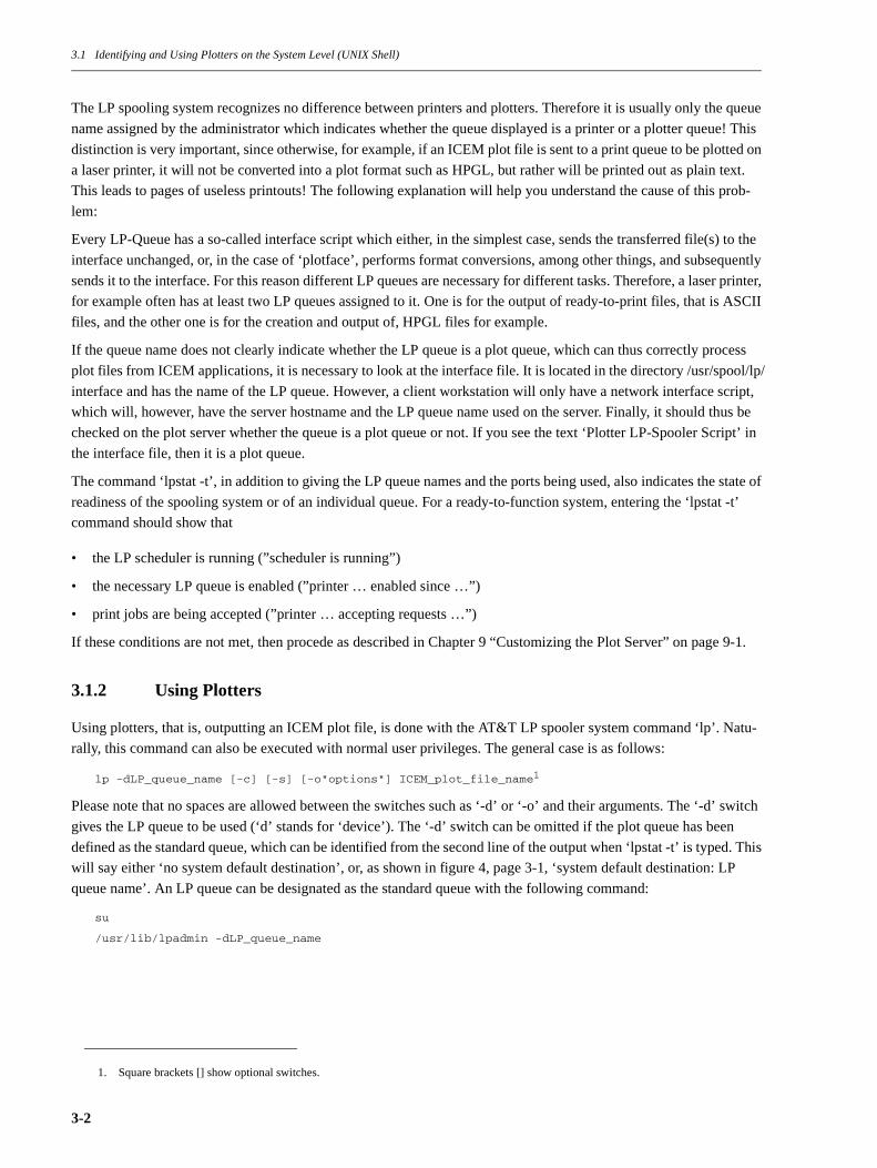
The LP spooling system recognizes no difference between printers and plotters. Therefore it is usually only the queue
name assigned by the administrator which indicates whether the queue displayed is a printer or a plotter queue! This
distinction is very important, since otherwise, for example, if an ICEM plot file is sent to a print queue to be plotted on
a laser printer, it will not be converted into a plot format such as HPGL, but rather will be printed out as plain text.
This leads to pages of useless printouts! The following explanation will help you understand the cause of this prob-
lem:
Every LP-Queue has a so-called interface script which either, in the simplest case, sends the transferred file(s) to the
interface unchanged, or, in the case of ‘plotface’, performs format conversions, among other things, and subsequently
sends it to the interface. For this reason different LP queues are necessary for different tasks. Therefore, a laser printer,
for example often has at least two LP queues assigned to it. One is for the output of ready-to-print files, that is ASCII
files, and the other one is for the creation and output of, HPGL files for example.
If the queue name does not clearly indicate whether the LP queue is a plot queue, which can thus correctly process
plot files from ICEM applications, it is necessary to look at the interface file. It is located in the directory /usr/spool/lp/
interface and has the name of the LP queue. However, a client workstation will only have a network interface script,
which will, however, have the server hostname and the LP queue name used on the server. Finally, it should thus be
checked on the plot server whether the queue is a plot queue or not. If you see the text ‘Plotter LP-Spooler Script’ in
the interface file, then it is a plot queue.
The command ‘lpstat -t’, in addition to giving the LP queue names and the ports being used, also indicates the state of
readiness of the spooling system or of an individual queue. For a ready-to-function system, entering the ‘lpstat -t’
command should show that
• the LP scheduler is running (”scheduler is running”)
• the necessary LP queue is enabled (”printer … enabled since …”)
• print jobs are being accepted (”printer … accepting requests …”)
If these conditions are not met, then procede as described in Chapter 9 “Customizing the Plot Server” on page 9-1.
3.1.2 Using Plotters
Using plotters, that is, outputting an ICEM plot file, is done with the AT&T LP spooler system command ‘lp’. Natu-
rally, this command can also be executed with normal user privileges. The general case is as follows:
lp -dLP_queue_name [-c] [-s] [-o"options"] ICEM_plot_file_name1
Please note that no spaces are allowed between the switches such as ‘-d’ or ‘-o’ and their arguments. The ‘-d’ switch
gives the LP queue to be used (‘d’ stands for ‘device’). The ‘-d’ switch can be omitted if the plot queue has been
defined as the standard queue, which can be identified from the second line of the output when ‘lpstat -t’ is typed. This
will say either ‘no system default destination’, or, as shown in figure 4, page 3-1, ‘system default destination: LP
queue name’. An LP queue can be designated as the standard queue with the following command:
su
/usr/lib/lpadmin -dLP_queue_name
1. Square brackets [] show optional switches.
3-2

3.1 Identifying and Using Plotters on the System Level (UNIX Shell)
The switch ‘-o’ can send options which control the plot output to the LP spooling system (see page 14). Finally, the
name of the file to be plotted must follow. Only one file can be specified; all other files will be ignored (this is not true
for print queues!). You can find the other switches in the Online Manual by typing the command ‘man lp’. However,
since some of the switches depend directly on the interface script which is used, they sometimes have no effect (e.g.,
number of copies).
Please observe the following when using the lp command:
• The file to be plotted must be in the ICEM application plot formats:
1. ICEM DDN, ‘tape9’ (not ‘CGM’!),
2. ICEM Surf, ‘NPFILE’ or
3. Duct, ‘*.npf’
• The file to be plotted must have UNIX global read permission, since the LP spooling system accesses the file with
the user ID ‘lp’. Its permissions can be changed with the command ‘chmod +r plot_file_name’, if necessary.
• Likewise the directory which contains the plot file must have global read and execute permission. You can do this
by typing the command ‘chmod +rx directory_name’.
Version 2.1 of the ‘plotface’ file takes into account the fact that, starting with IRIX 5.x, the lp command no longer dis-
plays an error message if ‘lp’ has problems with permissions. Therefore ‘plotface’ writes an unambiguous error mes-
sage in the log file ‘plotlog’. The file ‘plotlog’ for each plot queue is always located (only) on the plot server in the
directory /usr/spool/lp/request/plot_queue_name. When there are problems, it should always be the starting point
when investigating the possible causes of errors (see Chapter 9 “Customizing the Plot Server” on page 9-1).
The following options can be passed on to the interface script ‘plotface’ with the lp command using the ‘-o’ switch. If
several options should be necessary, they can either be passed on individually, i.e., each having its own ‘-o’ switch
and directly following argument, or they can be bundled together, with a single ‘-o’ switch followed by a string sur-
rounded by quotation marks which contains the individual arguments; within the string the individual arguments are
separated from one another with spaces.
• rot
This option (rotation) rotates the plot by 90× counter-clockwise. Example:
lp -dhp7475 -orot tape9
• ascale
This option (auto scale) changes the standard behavior of reproducing a plot true to scale. Instead, the plot will be
scaled down onto the existing plotting surface if it is too big. Example:
lp -dc1044 -oascale tape9
• A0 or a0 through A4 or a4
This option only has effect in the support of HPGL(/2)-compatible output devices and specifies the plotting sur-
face or the HPGL P1/P2 positions. Example:
lp -dhp650c -oa0 tape9
• An example of using several options simultaneously:
lp -dlaserjet -o’a4 rot ascale’ tape9
3-3

3.2 Identifying and Using Plotters under the ICEMview User Interface
3.1.3 Managing Printing and Plotting Jobs
Printing and plotting jobs are managed with the ‘lpstat’ command you are already familiar with, as well as the ‘cancel’
command, which allows plotting jobs which are still pending in the LP queue to be removed. When the ‘lpstat’ com-
mand is entered every printing or plotting job which has not yet been processed is displayed in the form queue_name-
ID. If, for any reason, you would like to cancel the processing of a particular plotting job, you can do this by entering
the command ‘cancel queue_name-ID’. With your user privileges you may only remove your own jobs. With supe-
ruser privileges, that is after you have entered the ‘su’ command, you may also remove printing and plotting jobs of
other users. A ‘cancel’ command issued from a client workstation also removes the plotting job which is automati-
cally created on the plot server. You can find further details in the Online Manual by entering the command ‘man can-
cel’.
3.2 Identifying and Using Plotters under the ICEMview1 User Interface
Figure 5 ICEM view Icon Catalog page
The optional ICEM product ICEMview opens a completely intuitive way of printing and plotting to you. Assuming
that the administrator has integrated the defined LP queues (see below), the ICEMview printer and plotter icons will
be available to every user in the WorkSpace (IRIX 4.x) or on the IndigoMagic Desktop (IRIX 5.x) for every LP queue
which is present. On the IndigoMagic Desktop, that is, under IRIX 5.x, you will find these icons on the ICEMview
Icon Catalog page (see figure 5), and in the WorkSpace (IRIX 4.x) you will find them in the WorkSpace window.
The ICEMview icons distinguish between print queues and plot queues, that is, queues which are suitable for ICEM
plot files (see figure 5 and figure 6). This feature uniquely marks the function of several queues which might be
present for a single output device. Printing and plotting are done intuitively by dragging and dropping a print2 or plot
file onto one of the ICEMview queue icons. After that, a graphical dialog box appears in which the options mentioned
1. IRIX only.2. Several files can also be dragged and dropped onto a printer icon simultaneously.
3-4

3.2 Identifying and Using Plotters under the ICEMview User Interface
in the previous section or lp command switches can be set by clicking switches or filling out text fields (see figure 7
and figure 8). As is normal under ICEMview, the settings can be saved or reset to the default values through the pop-
up menu which appears when the right mouse button is pressed when the cursor is inside the dialog box.
Figure 6 ICEM view printer and plotter icons
ICEMview also implicitly sees to it that plot files and directories have the correct permissions1. Another way it makes
your work easier is the elegant manner in which you can view a plot queue’s log file ‘plotlog’ (which is located on the
Plotserver) from every workstation. This is done by performing an ‘ALT-OPEN’2 on the desired plotter icon. ICEM-
view automatically displays the log file, which is located on the plot server, in its own window on a client workstation.
Figure 7 ICEM view plotter dialog box
The possible options given on page 14 for sending a plot with the ‘lp’ command can naturally also be entered in the
ICEMview plotter dialog box. Simply enter the desired option in the Options text field. If there is more than one
option, then separate them from one another with a space. Please note that the ‘-o’ switch of the ‘lp’ command is not
necessary here! Options which are constantly needed can also be stored, as was already described. Since the ICEM-
view plotter dialog box always appears, you can easily check options which might have been stored in this way.
1. This can only take place for files for which the user has the appropriate privileges to change.2. Double-clicking with the mouse on the ICEMview plotter icon while simultaneously pressing the ALT key on the keyboard.
3-5
3.2 Identifying and Using Plotters under the ICEMview User Interface
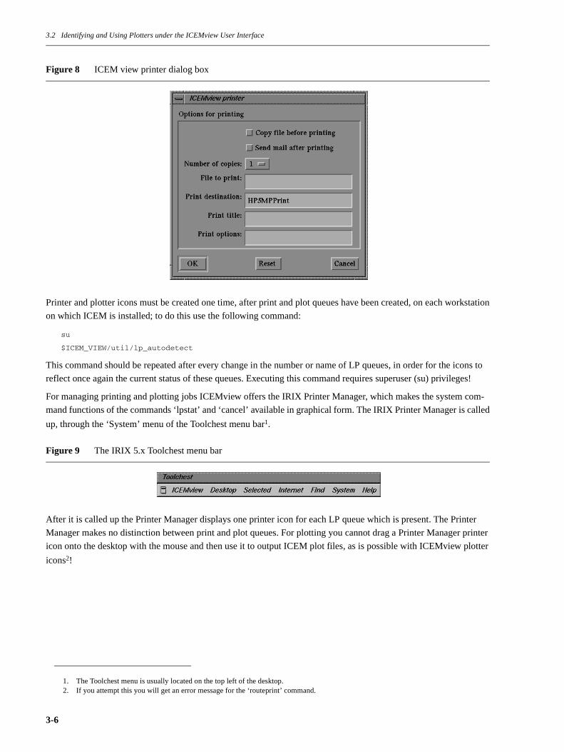
Figure 8 ICEM view printer dialog box
Printer and plotter icons must be created one time, after print and plot queues have been created, on each workstation
on which ICEM is installed; to do this use the following command:
su
$ICEM_VIEW/util/lp_autodetect
This command should be repeated after every change in the number or name of LP queues, in order for the icons to
reflect once again the current status of these queues. Executing this command requires superuser (su) privileges!
For managing printing and plotting jobs ICEMview offers the IRIX Printer Manager, which makes the system com-
mand functions of the commands ‘lpstat’ and ‘cancel’ available in graphical form. The IRIX Printer Manager is called
up, through the ‘System’ menu of the Toolchest menu bar1.
Figure 9 The IRIX 5.x Toolchest menu bar
After it is called up the Printer Manager displays one printer icon for each LP queue which is present. The Printer
Manager makes no distinction between print and plot queues. For plotting you cannot drag a Printer Manager printer
icon onto the desktop with the mouse and then use it to output ICEM plot files, as is possible with ICEMview plotter
icons2!
1. The Toolchest menu is usually located on the top left of the desktop.2. If you attempt this you will get an error message for the ‘routeprint’ command.
3-6
3.2 Identifying and Using Plotters under the ICEMview User Interface
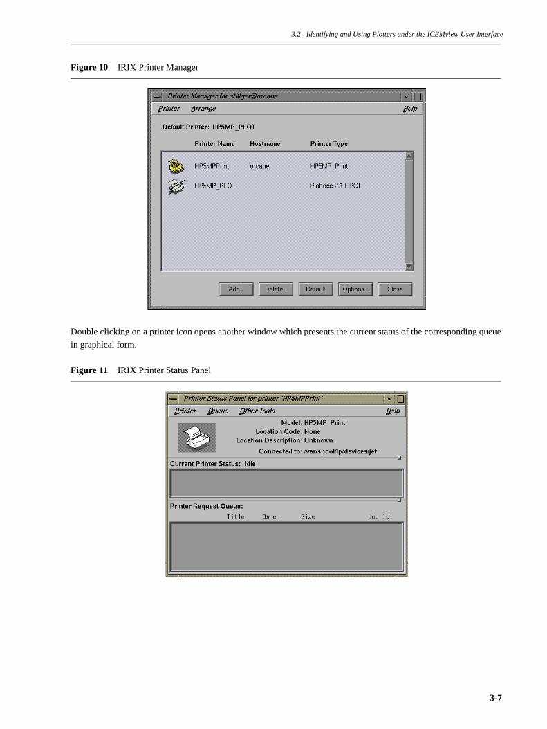
Figure 10 IRIX Printer Manager
Double clicking on a printer icon opens another window which presents the current status of the corresponding queue
in graphical form.
Figure 11 IRIX Printer Status Panel
3-7

3.3 Plotting from Inside an ICEM Application
Jobs to be removed can simply be selected with the mouse and removed from the queue through the ‘Queue’ pull-
down menu. The status indications of the IRIX Printer Manager are very much defined by the properties of the
Impressario1 printer drivers. For this reason you should not worry about the warnings and apparent error messages
which appear in the Printer Status Panel shown in figure 11. Standard printer and especially ‘plotface’ interface script
files cannot offer the expected Impressario driver information. This is a superficial flaw.
3.3 Plotting from Inside an ICEM Application
The highest form of integration of the ICEM PlotServer Package is provided when it is not necessary to quit the ICEM
application in order to output the plot file. Creation of the application-specific plot file is seamlessly connected with
passing it on to one of the defined plot queues. This requires at least one customization to reflect the currently-used
plot queue names, but can also entail customizing menus in this regard, which, for example, allow convenient selec-
tion of the output device from within the ICEM application. It is important to understand that, in the end, the ICEM
application has to issue an lp command with the file to be plotted. This considerably facilitates integration with the
ICEM applications. The following paragraphs show you examples of the standard integration with the ICEM applica-
tions DDN, Surf, and Duct.
3.3.1 ICEM DDN
Even the basic version of ICEM DDN offers integration of the ICEM PlotServer Package which is implemented
through the basic Orga modules. This integration puts the available plot queues into a DDN menu, whose menu items
can be expanded. The associated Orga control file is called ‘autoplot’ and is usually in the ICEM DDN ‘common’
area, that is in the /icem/common/orga directory. The block of this Orga control file for the DDN menu can be custom-
ized. Figure 12 shows the DDN menu text for two plot queues in bold type. A maximum of 19 menu entries can be
made. If more are needed, submenus can be used.
1. Optional IRIX product to support PCL- and ESC/P-compatible printers.
3-8

3.3 Plotting from Inside an ICEM Application
Figure 12 Orga Autoplot DDN menu definitions, etc.
The area for creating the DDN plot file ‘tape9’ (trace part) can, as a rule, remain unchanged. Figure 13 shows the sec-
tion of the Orga autoplot file which defines the DDN-internal command sequences to create DDN plot files in ‘tape9’
format. This area is followed by the definition of the UNIX commands which are subsequently to be executed (see fig-
ure 14). Here the current plot queue name should be customized after the ‘-d’ switch of the respective lp command. It
can be seen from the UNIX commands which have already been entered that even this solution sees to it that the plot
files and their directory have the correct UNIX permissions. Once all customizations have been made the total plotting
process is reduced to the DDN-internal selection of an Orga DIN drawing border and the subsequent selection of the
desired plot queue. The creation of the plot file and its output on the output device connected with the plot queue is
completely automatic (‘autoplot’). For more detailed information on the use of the Orga modules please consult the
DDN literature.
***************************************************************************** ** A U T O M A T I C P L O T T I N G ** *****************************************************************************
MENU/NODISPLAY ’AUTOMATIC PLOTTING ’ ISW CONTROL ’CURRENT DRAWING ’ PLTYP PLOT_AKT ’DISPLAY PLOT STATUS ’ PLSTAT QUEUE
SUBMENU/PLTYP ’OUTPUT DEVICE: ’ ISWTYP CONTROL ’QMS-LASERDRUCKER ’ ’CALCOMP 1043 ’ SUBMENU/PLSTAT ’DISPLAY PLOT STATUS ’ ISWQUE CONTROL ’ - OF ALL REQUESTS ’ ’ - OF LOCAL REQUESTS ONLY’
3-9

3.3 Plotting from Inside an ICEM Application
Figure 13 Orga Autoplot DDN trace definition, etc.
CONTROL/PLOT_AKT
MODAL RTL=1 REPLACE=1PROCEDURE LP_SYSTEMTRACEFILE PLOTGEN_AKT TRACEFILE/UNIX:’PLOTGEN_AKT’ ’PLOT ABSCHICKEN’ ’orga/aptrace’ ’M’ ’F.7.2’ * Enter plot menu ’5.1’ * Plot current drawing ’1’ * Change plot modals ’9.1’ * Plot format is tape9 ’1.2’ * Paper standard is international ’2.6’ * Nonstandard paper size: ’PAPERX’ * X-SIZE from retrieved frame ’PAPERY’ * Y-SIZE from retrieved frame ’]’ ’3.1’ * Plot region: Entire plot frame ’4.2’ * Plot extent: Entire part ’5.4’ * Plot origin: Lower left ’6.3’ * Plot scale: Use draft scale ’DRAFSC’ ’7.1’ * Calculate plot tolerance to match draft scale ’0.000646+1/(500*DRAFSC)’ ’8.1’ * Plot mode interactive ’]’ ’2’ * Initialize plot file ’tape9’ ’Y’ * Overwrite an existing file ’3’ * Create the plot file interactive ’F.7.14.3.1.3’ * Execute the command file to submit plottingUNIX: ’orga/approc &’ ’F.M’ ’|’ ’ ’ ’ PROZESS ABGESCHICKT. ’ ’|’
3-10

3.3 Plotting from Inside an ICEM Application
Figure 14 Orga autoplot procedure definition
3.3.2 ICEM Surf
ICEM Surf offers just as convenient integration with the ICEM PlotServer Package as ICEM DDN does. Here too, a
menu appearing in ICEM Surf can be customized as desired. Likewise, the features for users’ convenience range from
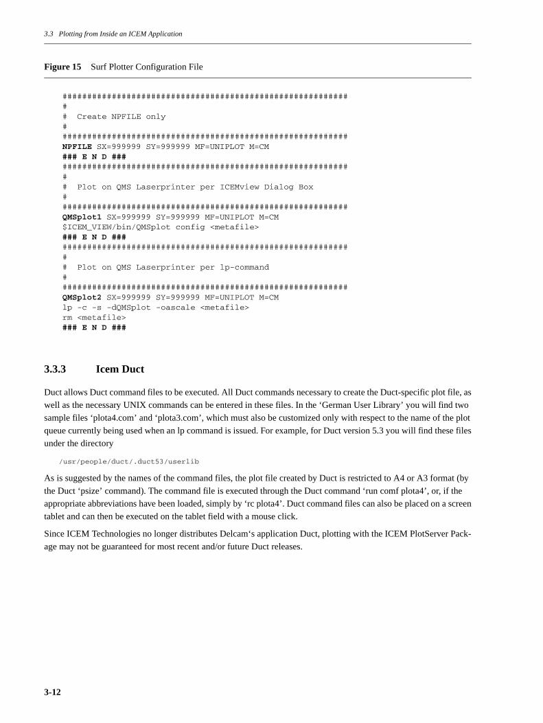
fully-automatic creation of plot files to output on the desired plot queue. The configuration file for Surf is called
‘plotter_configuration’ and is located in the directory /surf/config. This file contains a section for each menu
item which defines the creation of the Uniplot metafile ‘NPFILE’ and passes it on to the lp command. As an example,
figure 15 shows three Surf plot menu items. The first menu item ‘NPFILE’ only generates a Surf plot file (NPFILE),
without passing it on. The second menu item ‘QMSplot1’ uses the ICEMview1 plotter dialog box to send off the plot
file, which allows plotting options to be passed on in a flexible manner without having to provide separate menu items
for them. The third menu item in the example passes the Surf plot file directly on to the ICEM PlotServer Package
through the lp command.
1. Applicable only for IRIX with ICEMview installed.
************************** SEND PLOT TO LP QUEUE **************************PROCEDURE/UNIX:’LP_SYSTEM’ ’NO_EXECUTION’ ’orga/approc’UNIX: ’#!/bin/csh -f’UNIX: ’chmod o+rx plots plots/tape9’UNIX: ’switch ([ISWTYP])’UNIX: ’case 1:’UNIX: ’ lp -c -s -dqms plots/tape9’UNIX: ’ breaksw’UNIX: ’case 2:’UNIX: ’ lp -c -s -dcal_1043 plots/tape9’UNIX: ’ breaksw’UNIX: ’default:’UNIX: ’ echo "No plotter customization given."’UNIX: ’endsw’UNIX: ’rm plots/tape9 >& /dev/null’
3-11
3.3 Plotting from Inside an ICEM Application
Figure 15 Surf Plotter Configuration File
3.3.3 Icem Duct
Duct allows Duct command files to be executed. All Duct commands necessary to create the Duct-specific plot file, as
well as the necessary UNIX commands can be entered in these files. In the ‘German User Library’ you will find two
sample files ‘plota4.com’ and ‘plota3.com’, which must also be customized only with respect to the name of the plot
queue currently being used when an lp command is issued. For example, for Duct version 5.3 you will find these files
under the directory
/usr/people/duct/.duct53/userlib
As is suggested by the names of the command files, the plot file created by Duct is restricted to A4 or A3 format (by
the Duct ‘psize’ command). The command file is executed through the Duct command ‘run comf plota4’, or, if the
appropriate abbreviations have been loaded, simply by ‘rc plota4’. Duct command files can also be placed on a screen
tablet and can then be executed on the tablet field with a mouse click.
Since ICEM Technologies no longer distributes Delcam‘s application Duct, plotting with the ICEM PlotServer Pack-
age may not be guaranteed for most recent and/or future Duct releases.
############################################################ Create NPFILE only###########################################################NPFILE SX=999999 SY=999999 MF=UNIPLOT M=CM### E N D ############################################################### Plot on QMS Laserprinter per ICEMview Dialog Box###########################################################QMSplot1 SX=999999 SY=999999 MF=UNIPLOT M=CM$ICEM_VIEW/bin/QMSplot config <metafile>### E N D ############################################################### Plot on QMS Laserprinter per lp-command###########################################################QMSplot2 SX=999999 SY=999999 MF=UNIPLOT M=CMlp -c -s -dQMSplot -oascale <metafile>rm <metafile>### E N D ###
3-12
Chapter 4 Installing the ICEM PlotServer Package
Chapter 4 Installing the ICEM PlotServer Package
Starting with version 4.0 the ICEM PlotServer Package is supplied in ICEM Installer format on the CD-ROM of
ICEM DDN 3.3.01 or higher and ICEM Surf 3.0.01 or higher. Additionally a cartridge version is also available. The
ICEM Installer necessary for installation is located on CD-ROM in the directory /installer, on cartridge it is the first
‘tar’-tape file itself.
If an older version of the ICEM PlotServer Package (e.g., 3.03 or 3.02) should already be in use on the workstation
where the new version is to be installed, you should definitely backup at least the directories /usr/spool/lp/interface
and /usr/applications/uniplot before installing the new version.
• If you are installing from Cartridge you at first have to load the ICEM Installer program from the cartridge and
then to execute it. Please continue reading with csection 4.1 “Preparing Installation from Cartridge” on page 4-1.
• If you are installing from CD-ROM you are able to execute the ICEM Installer program directly from the CD-
ROM. Please continue reading with section 4.2 “Preparing Installation from CD-ROM” on page 4-2.
4.1 Preparing Installation from Cartridge
The ICEM Installer which is on the cartridge must first be loaded onto the workstation’s hard disk and then launched
in order to install the ICEM PlotServer Package. To do this proceed as follows:
1. Insert the cartridge into a local cartridge drive or one that is accessible over the network.
2. On the IRIX workstation where you want to install the ICEM PlotServer Package either log in as ‘root’ or assume
superuser privileges by typing
su
3. If you do not want to install the ICEM Installer permanently (recommended), you can temporarily load it into the
directory /tmp, execute it, and then delete it from the hard drive. Thus, you should type in:
cd /tmp
4. Now load the ICEM Installer from the cartridge by entering:
tar xvof remotehost:/dev/tape
where ‘remotehost’ is replaced by the computer name of the workstation to which the cartridge drive is connected.
If the cartridge drive is locally connected, it is sufficient to enter:
tar xvo
If you cannot communicate with your cartridge drive on the workstation through the standard name /dev/tape, then
you must use the complete device name, thus, for example /dev/mt/tps0d2 (for a cartridge drive having SCSI ID
2).
Step 4 will load a directory with the name ‘installer’ into the current directory, that is, /tmp.
5. Now execute the ICEM Installer program:
cd installer
./ICEM_installer
4-1

4.2 Preparing Installation from CD-ROM
Please proceed now to the third paragraph (”After you have started the ICEM Installer program, ...) in section 4.3
“Installation with the ICEM Installer” on page 4-3, where the key steps of the installation of the ICEM PlotServer
Package are described.
4.2 Preparing Installation from CD-ROM
To be able to install from CD-ROM you must have a connected and mounted CD-ROM device.If your CD-ROM
device won’t be connected directly to your system you have to execute the following steps on the server workstation
for the CD-ROM device first and then mount the CD-ROM directory to your system.
Execute the following steps to mount the CD-ROM device. If you have any further questions about mounting the CD-
ROM, please refer to the SGI Administrators Guide for more information about mounting and unmounting file sys-
tems.
You must be logged in as root to mount the CD-ROM.
su
Display the current system configuration to determine available unit to mount the CD-ROM on.
hinv
SGI Systems have 7 units that devices can be connected to. Choose an available unit for mounting the CD-ROM
drive. Units 0-3 are usually reserved for system devices. For this example unit 7 will be used.
The CD-ROM drive has a switch that can be set to the unit number that will be used for mounting. Set the switch to an
available unit.
Shutdown the system and connect the CD-ROM to a SCSI interface port. Place the ICEM 3.3.01 software disc into the
CD-ROM player. Power up the system and display the system configuration as before, the CD-ROM should appear.
hinv
look forunit andcontroller num-ber here
1 100 MHZ IP22 ProcessorFPU: MIPS R4010 Floating Point Chip Revision: 0.0CPU: MIPS R4000 Processor Chip Revision: 3.0On-board serial ports: 2On-board bi-directional parallel portData cache size: 8 KbytesInstruction cache size: 8 KbytesMain memory size: 128 MbytesIntegral Ethernet: ec0, version 1Tape drive: unit 6 on SCSI controller 0: QIC 150Disk drive: unit 2 on SCSI controller 0Disk drive: unit 1 on SCSI controller 0Integral SCSI controller 0: Version ...Iris Audio Processor: version A2 revision 4.1.0Graphics board: Indy 8-bitVino video: unit 0, revision 0, Indycam connected
4-2
4.3 Installation with the ICEM Installer
To mount the CD-ROM device, enter:
mkdir /CDROM
mount -o ro -t efs /dev/dsk/dksXdYs7 /CDROM
where X is the controller number and Y is an available unit number.
4.3 Installation with the ICEM Installer
Note:
This section implies installation from an ICEM DDN-CD.
Now that the CD-ROM has been mounted, display the contents of the installer directory. You should substitute /
CDROM in the following 2 commands, if your device is named /cdrom.
ls /CDROM/installer
Execute the ICEM Installer from the CD-ROM on a system console or supported X-terminal as follows:
/CDROM/installer/ICEM_installer
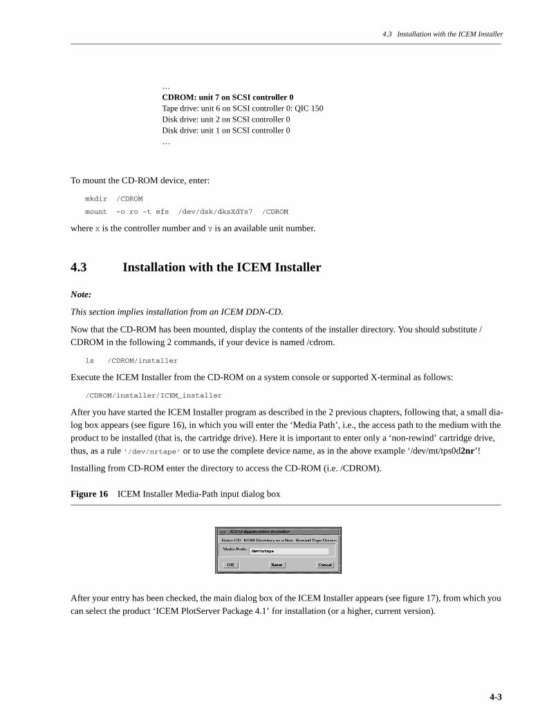
After you have started the ICEM Installer program as described in the 2 previous chapters, following that, a small dia-
log box appears (see figure 16), in which you will enter the ‘Media Path’, i.e., the access path to the medium with the
product to be installed (that is, the cartridge drive). Here it is important to enter only a ‘non-rewind’ cartridge drive,
thus, as a rule ‘/dev/nrtape’ or to use the complete device name, as in the above example ‘/dev/mt/tps0d2nr’!
Installing from CD-ROM enter the directory to access the CD-ROM (i.e. /CDROM).
Figure 16 ICEM Installer Media-Path input dialog box
After your entry has been checked, the main dialog box of the ICEM Installer appears (see figure 17), from which you
can select the product ‘ICEM PlotServer Package 4.1’ for installation (or a higher, current version).
…CDROM: unit 7 on SCSI controller 0Tape drive: unit 6 on SCSI controller 0: QIC 150Disk drive: unit 2 on SCSI controller 0Disk drive: unit 1 on SCSI controller 0…
4-3
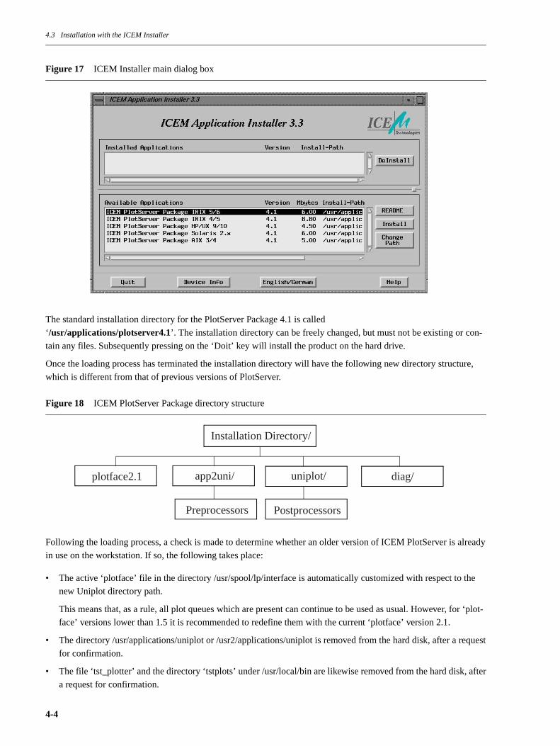
4.3 Installation with the ICEM Installer
Figure 17 ICEM Installer main dialog box
The standard installation directory for the PlotServer Package 4.1 is called
‘/usr/applications/plotserver4.1’. The installation directory can be freely changed, but must not be existing or con-
tain any files. Subsequently pressing on the ‘Doit’ key will install the product on the hard drive.
Once the loading process has terminated the installation directory will have the following new directory structure,
which is different from that of previous versions of PlotServer.
Figure 18 ICEM PlotServer Package directory structure
Following the loading process, a check is made to determine whether an older version of ICEM PlotServer is already
in use on the workstation. If so, the following takes place:
• The active ‘plotface’ file in the directory /usr/spool/lp/interface is automatically customized with respect to the
new Uniplot directory path.
This means that, as a rule, all plot queues which are present can continue to be used as usual. However, for ‘plot-
face’ versions lower than 1.5 it is recommended to redefine them with the current ‘plotface’ version 2.1.
• The directory /usr/applications/uniplot or /usr2/applications/uniplot is removed from the hard disk, after a request
for confirmation.
• The file ‘tst_plotter’ and the directory ‘tstplots’ under /usr/local/bin are likewise removed from the hard disk, after
a request for confirmation.
Installation Directory/
Preprocessors Postprocessors
plotface2.1 uniplot/ diag/app2uni/
4-4
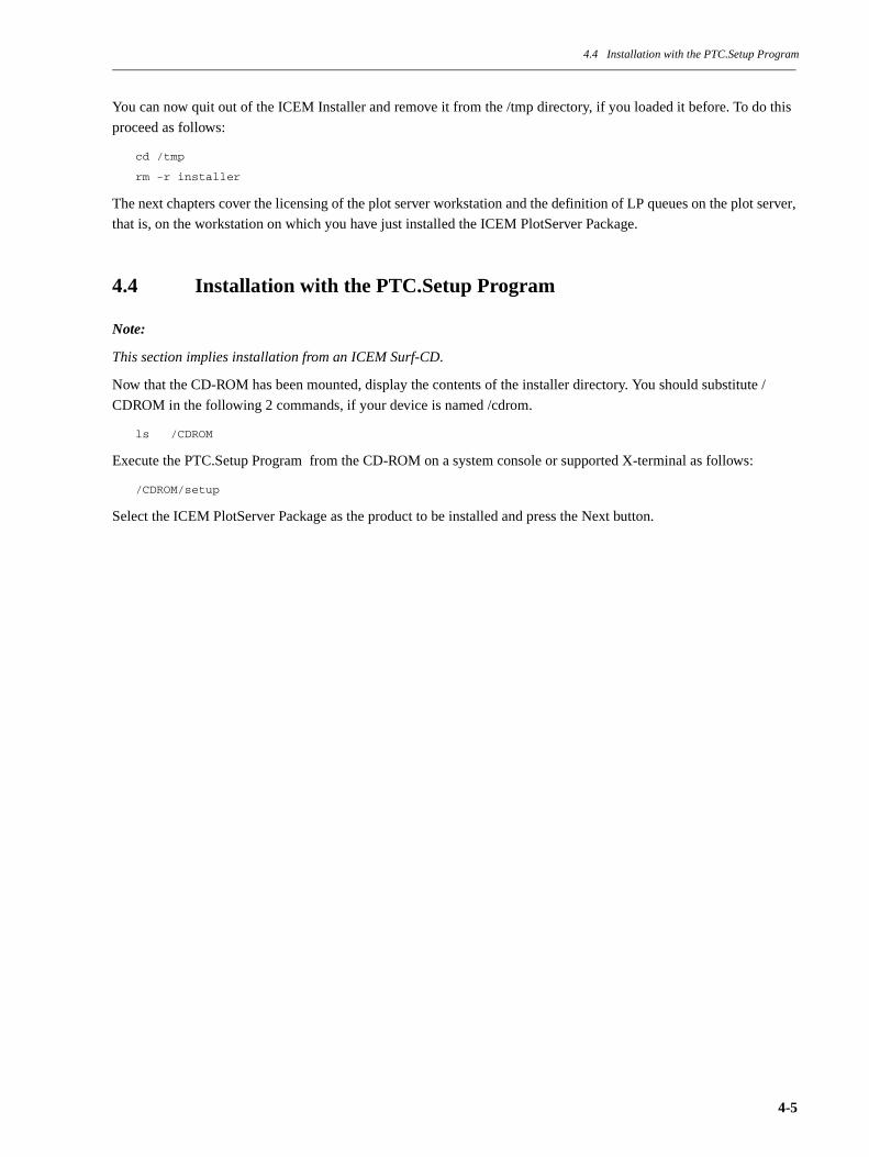
4.4 Installation with the PTC.Setup Program
You can now quit out of the ICEM Installer and remove it from the /tmp directory, if you loaded it before. To do this
proceed as follows:
cd /tmp
rm -r installer
The next chapters cover the licensing of the plot server workstation and the definition of LP queues on the plot server,
that is, on the workstation on which you have just installed the ICEM PlotServer Package.
4.4 Installation with the PTC.Setup Program
Note:
This section implies installation from an ICEM Surf-CD.
Now that the CD-ROM has been mounted, display the contents of the installer directory. You should substitute /
CDROM in the following 2 commands, if your device is named /cdrom.
ls /CDROM
Execute the PTC.Setup Program from the CD-ROM on a system console or supported X-terminal as follows:
/CDROM/setup
Select the ICEM PlotServer Package as the product to be installed and press the Next button.
4-5

4.4 Installation with the PTC.Setup Program
Figure 19 Main Window of the PTC.Setup Program
In the PTC.Setup window you will see a proposal where the PlotServer Package is to be installed. At this stage you
can select any other directory, provided that this directory meets one of the following three prerequisites:
• The directory is an existing ICEM PlotServer directory and contains a previous version of the ICEM PlotServer
Package.
• The directory exists, and it is empty.
• The direcory does not exist and it will be newly created by the PTC.Setup program.
Press the Next button and execute the consecutive steps. The installation status will be displayed in the PTC.Setup
window. When the installation is finished you may exit the PTC.setup program.
The next chapters cover the licensing of the plot server workstation and the definition of LP queues on the plot server,
that is, on the workstation on which you have just installed the ICEM PlotServer Package.
4-6
4.5 Licensing
4.5 Licensing
The ICEM PlotServer Package has to be FLEXlm node locked licensed for the plotserver workstation. Client worksta-
tions don’t need a license. The license code is expected in the file
/icem/lic/license.dat
If you use a different path or file name for the license file you have to use the environment variable
LM_LICENSE_FILE. Due to the fact that the AT&T LP spooling system runs independant from the user environ-
ment this environment variable must be set in the customizing area of the file ‚plotface‘ (see section 9.1 “Customizing
the Access Path of the License File” on page 9-4 ).
See the ICEM Licensing Manual for more details.
4.6 Deinstalling the ICEM PlotServer Package
If you have installed the ICEM PlotServer Package with the ICEM Installer program from a DDN-CD, you can use
this program for the deinstallation as well. All product-related information and files will be cleanly deleted from your
system. Execute the ICEM Installer as described in the previous chapters and then select from the installed applica-
tions list the application(s) you want to deinstall (see figure 17, page 4-4, ICEM Installer main dialog box).
If you have installed the ICEM PlotServer Package with the PTC.Setup program from an ICEM Surf-CD, you
should just delete the PlotServer installation directory by executing the following command
rm –r <plotserver_install_path>
4-7

4.5 Licensing
4-8
Chapter 5 Creating a Plot Queue on the Plot Server
Chapter 5 Creating a Plot Queue on the Plot Server
Once the ICEM PlotServer Package has been installed, as described in the preceding chapter, the plot server has all
the necessary components for creating and defining special plot queues. This chapter will now show you the proce-
dure for creating a plot queue.
The AT&T LP spooling system uses so-called interface script files. As a rule, these are executable ASCII files
(scripts), but can also be binary programs as, for example, in the case of Impressario printer drivers. The interface
script files are executed by the LP spooler and process and output the file passed to them through an ‘lp’ command.
All files and directories belonging to the AT&T spooling system are in the directory /usr/spool/lp. User and adminis-
trator commands are in the directories /usr/bin and /usr/lib. Templates of these interface script files are located in the
directory /usr/spool/lp/model. By contrast, the interface scripts of defined LP queues are located in the directory /usr/
spool/lp/interface. The procedure for creating a plot queue shown below always uses the ICEM PlotServer interface
script file ‘plotface’ from the /usr/spool/lp/model directory. As was already mentioned, when the plot queue has been
created, this file is copied into the /usr/spool/lp/interface directory. In the process, the name ‘plotface’ is changed to
the desired name of the plot queue. After the plot queue has been created with the copy of ‘plotface’ in the /usr/spool/
lp/interface directory as its interface script file, this file has to be customized to current requirements (using the ‘jot’ or
‘vi’ editors). Starting with ICEM PlotServer version 4.1, the tool ‘Mkplotter’ used in previous versions is no longer
supported. The customizations which are necessary or possible can be found in Chapter 8 “Removing a Plot Queue”
on page 8-1. as well as in Chapter 10 “Diagnosing and Correcting Plotting Problems” on page 10-1. in its subsections
on the operation of CAL907-, HPGL-, HPGL/2- and PostScript-compatible output devices.
But now let us turn to creating a plot queue on the plot server.
5.1 Creating a Plot Queue Using IRIX System Commands
IRIX allows an LP queue to be created with a single system command. This also represents the quickest way to create
a plot queue:
su
/usr/lib/lputil add port_name model_script_name plot_queue_name
Executing this command naturally requires superuser privileges (that is the reason for the ‘su’ command which might
be necessary). The four parameters have the following meanings:
• add instructs ‘lputil’ to create an LP queue.
• port_name must be a physical interface, that is, an RS232 interface /def/tty[12] or a parallel interface /dev/plp. The
latter should also be chosen if plot files are not to be output through a physical interface, but rather further pro-
cessed in any way. Earlier versions of ICEM PlotServer provided a pseudo-interface /dev/null for this purpose,
which, however, caused problems with the IRIX Printer Manager under IRIX 5.x.
• model_script_name gives the name of the template interface file in the directory /usr/spool/lp/model (without the
path).
• plot_queue_name defines the name which should be assigned to the plot queue. From this point on this name will
be used to communicate with the plot queue.
The command ‘lputil’, which, incidentally, has no entry in the IRIX Online Manual, takes care of all necessary
entries, directories, and permissions in the LP spooling system. In order for this command to function correctly, the
LP spooling system must be intact and the interface file under /usr/spool/lp/model must have the correct ownership
5-1
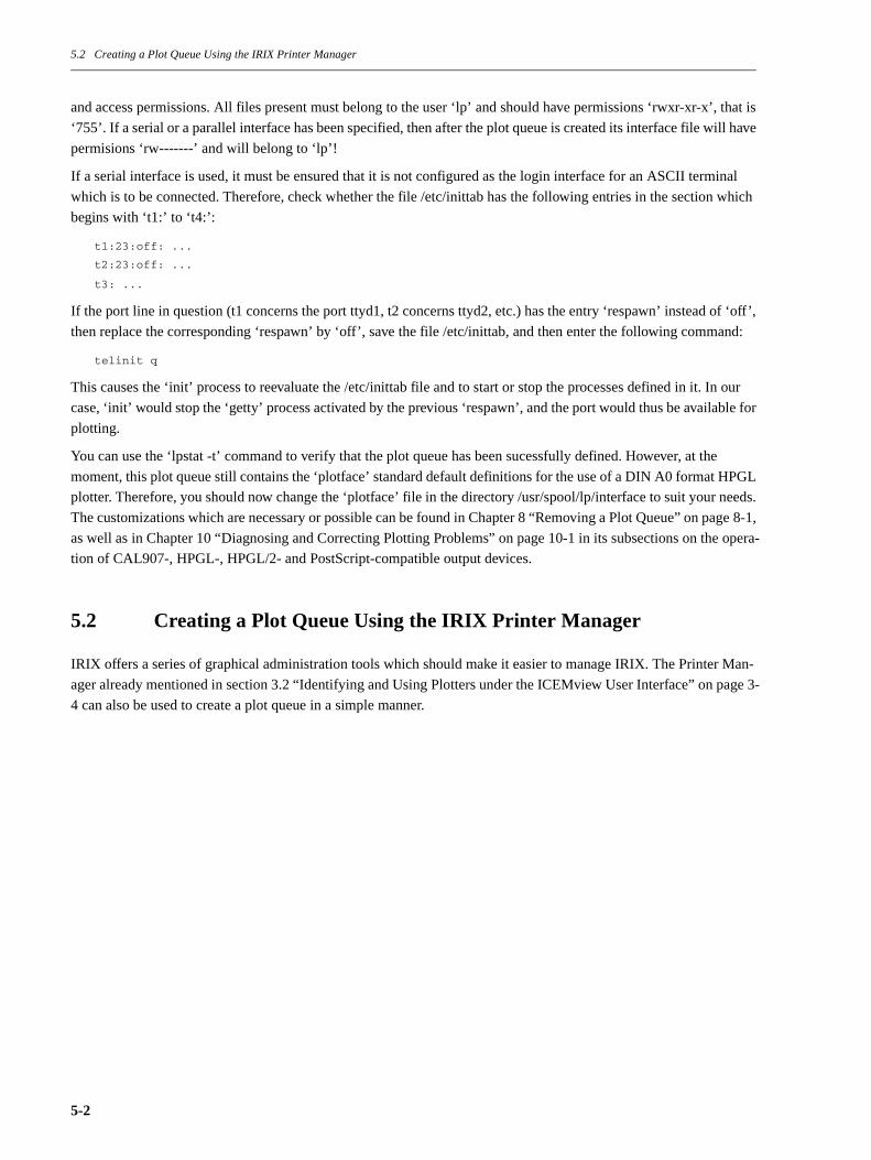
5.2 Creating a Plot Queue Using the IRIX Printer Manager
and access permissions. All files present must belong to the user ‘lp’ and should have permissions ‘rwxr-xr-x’, that is
‘755’. If a serial or a parallel interface has been specified, then after the plot queue is created its interface file will have
permisions ‘rw-------’ and will belong to ‘lp’!
If a serial interface is used, it must be ensured that it is not configured as the login interface for an ASCII terminal
which is to be connected. Therefore, check whether the file /etc/inittab has the following entries in the section which
begins with ‘t1:’ to ‘t4:’:
t1:23:off: ...
t2:23:off: ...
t3: ...
If the port line in question (t1 concerns the port ttyd1, t2 concerns ttyd2, etc.) has the entry ‘respawn’ instead of ‘off’,
then replace the corresponding ‘respawn’ by ‘off’, save the file /etc/inittab, and then enter the following command:
telinit q
This causes the ‘init’ process to reevaluate the /etc/inittab file and to start or stop the processes defined in it. In our
case, ‘init’ would stop the ‘getty’ process activated by the previous ‘respawn’, and the port would thus be available for
plotting.
You can use the ‘lpstat -t’ command to verify that the plot queue has been sucessfully defined. However, at the
moment, this plot queue still contains the ‘plotface’ standard default definitions for the use of a DIN A0 format HPGL
plotter. Therefore, you should now change the ‘plotface’ file in the directory /usr/spool/lp/interface to suit your needs.
The customizations which are necessary or possible can be found in Chapter 8 “Removing a Plot Queue” on page 8-1,
as well as in Chapter 10 “Diagnosing and Correcting Plotting Problems” on page 10-1 in its subsections on the opera-
tion of CAL907-, HPGL-, HPGL/2- and PostScript-compatible output devices.
5.2 Creating a Plot Queue Using the IRIX Printer Manager
IRIX offers a series of graphical administration tools which should make it easier to manage IRIX. The Printer Man-
ager already mentioned in section 3.2 “Identifying and Using Plotters under the ICEMview User Interface” on page 3-
4 can also be used to create a plot queue in a simple manner.
5-2

5.2 Creating a Plot Queue Using the IRIX Printer Manager
Figure 20 IRIX Printer Manager
However, there is a limitation in IRIX 4.x which allows the Printer Manager to define only one LP queue per inter-
face. But at least two LP queues are often required, especially for laser printers, one of which is used for outputting
ready-to-print documents, and the other for the output of vector plots from ICEM applications.
If you are logged into the system as ‘root’, you can call up the Printer Manager (see figure 20) from the ‘System’
menu of the Toolchest menu bar (see figure 9, page 3-6 The IRIX 5.x Toolchest menu bar). Clicking the ‘Add…’ but-
ton gives you another dialog box in which you can enter the desired queue name and connection (Local or Network).
A list box offers you templates, that is, interface script files.
5-3
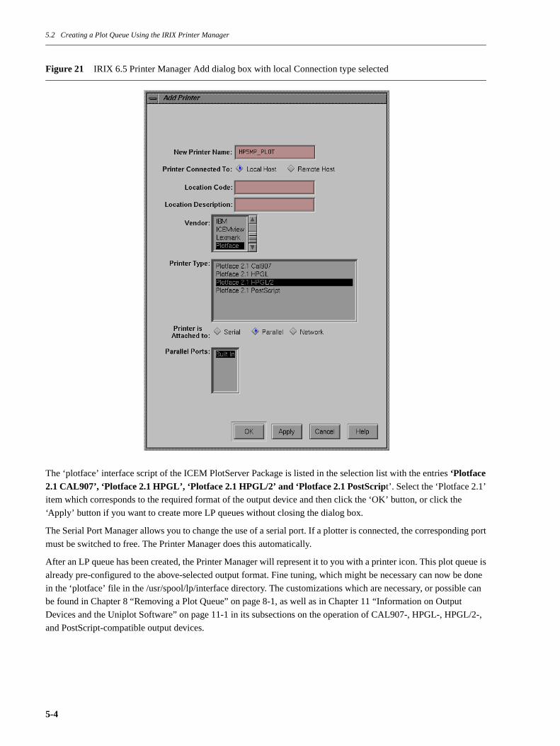
5.2 Creating a Plot Queue Using the IRIX Printer Manager
Figure 21 IRIX 6.5 Printer Manager Add dialog box with local Connection type selected
The ‘plotface’ interface script of the ICEM PlotServer Package is listed in the selection list with the entries ‘Plotface 2.1 CAL907’, ‘Plotface 2.1 HPGL’, ‘Plotface 2.1 HPGL/2’ and ‘Plotface 2.1 PostScript’. Select the ‘Plotface 2.1’
item which corresponds to the required format of the output device and then click the ‘OK’ button, or click the
‘Apply’ button if you want to create more LP queues without closing the dialog box.
The Serial Port Manager allows you to change the use of a serial port. If a plotter is connected, the corresponding port
must be switched to free. The Printer Manager does this automatically.
After an LP queue has been created, the Printer Manager will represent it to you with a printer icon. This plot queue is
already pre-configured to the above-selected output format. Fine tuning, which might be necessary can now be done
in the ‘plotface’ file in the /usr/spool/lp/interface directory. The customizations which are necessary, or possible can
be found in Chapter 8 “Removing a Plot Queue” on page 8-1, as well as in Chapter 11 “Information on Output
Devices and the Uniplot Software” on page 11-1 in its subsections on the operation of CAL907-, HPGL-, HPGL/2-,
and PostScript-compatible output devices.
5-4
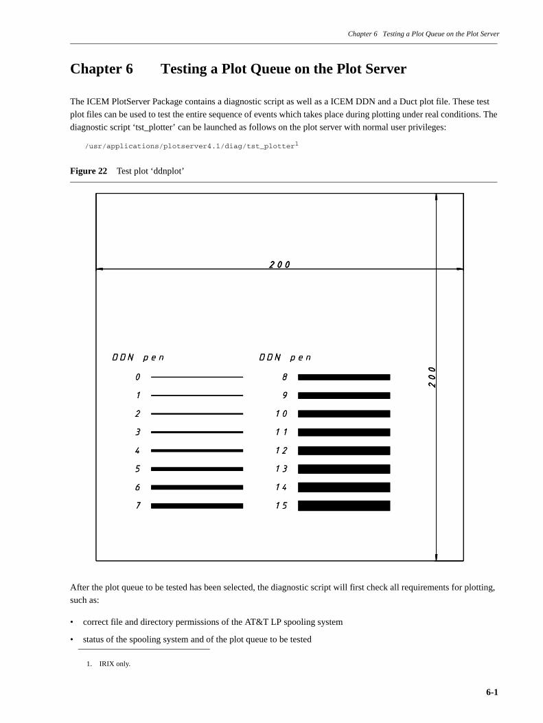
Chapter 6 Testing a Plot Queue on the Plot Server
Chapter 6 Testing a Plot Queue on the Plot Server
The ICEM PlotServer Package contains a diagnostic script as well as a ICEM DDN and a Duct plot file. These test
plot files can be used to test the entire sequence of events which takes place during plotting under real conditions. The
diagnostic script ‘tst_plotter’ can be launched as follows on the plot server with normal user privileges:
/usr/applications/plotserver4.1/diag/tst_plotter1
Figure 22 Test plot ‘ddnplot’
After the plot queue to be tested has been selected, the diagnostic script will first check all requirements for plotting,
such as:
• correct file and directory permissions of the AT&T LP spooling system
• status of the spooling system and of the plot queue to be tested
1. IRIX only.
6-1
Chapter 6 Testing a Plot Queue on the Plot Server
• entries in the ‘plotface’ file
• existence and correct permission of the necessary ICEM PlotServer components
• port permissions
and much more. Thus, for example, it will also check spooling system properties present in IRIX 4.x which could
block the spooling system. Next it gives data on the plotter format used, type of connection, etc. After that come notes
on the plotter settings and on the cable assignment for serial connection of the printer or plotter. Finally the ICEM
DDN test plot file is sent off with an ‘lp’ command. This test plot file, which is in a format smaller than DIN A4, con-
tains data for the use of sixteen plotter pens, as well as a dimensioned square whose edges are 200 mm long. Thus
even scaling and stroke width or pen color can be checked without wasting a lot of paper. Last, the log file ‘plotlog’ is
displayed in order to detect possible errors.
Experience with diagnostic scripts has shown that, for the most part, they can detect and eliminate all problems on the
part of the plot server. If a printer or plotter should still give no result, then the error can only have to do with the
transmission path (ports, cable) or with erroneous settings on the output device itself.
Naturally the test plots which are included can also be manually output for testing using the ‘lp’ command. The names
of the two test plots are
ddnplot
and
ductplot,
and they are likewise located in the directory
/usr/applications/plotserver4.1/diag.
The next page shows the output on the screen during the various phases of a sample run of the diagnostic script
tst_plotter’.
Figure 23 Diagnostic script ‘tst_plotter’
LP-SPOOLER PLOTTER TEST V. 4.1
This test script is for testing a ready defined LP-Spooler plotter, using the ’plotface’-interface script solution ...
1) The test script evaluates the existence of a defined ’plotface’ LP-Spooler. If several definitions exist, you will be asked which one to use for testing.
2) The test script checks ’correct’ LP-Spooler definition.
3) The test script displays the found relevant plot information and gives hints on the necessary cable connection and parameter settings on plotter site.
4) Then you will be asked to confirm the start of the plotter test. A prepared DDN or Duct plotfile will be processed through the defined LP-Spooler. The ’plotlog’-file will be displayed after the completion of the plot for error checking.
ok., let’s start testing ... press <CR>:
6-2

Chapter 6 Testing a Plot Queue on the Plot Server
Figure 24 Diagnostic script — phase 1
Figure 25 Diagnostic script — phase 2
Figure 26 Diagnostic script — phase 3
Figure 27 Diagnostic script — phase 4
PHASE 1) Checking for defined (local) LP-Spooler definitions ...
The following LP-Spooler plotter definitions were detected:
QMSplot
Please type in the name of the plotter to test:
PHASE 2) Checking defined LP-Spooler definition for QMSplot ...
LP-Spooler system seems to be ok.
Checking the customized values in the plotface file QMSplot ...
The customized values seem to be ok.
To continue, press <CR>:
PHASE 3) Hints for the plotter connection ...
You are using the POSTSC UNIPLOT driver with keyword PSLINE. The plot device (port) is /dev/plp. Please note a maximum Centronics cable length of 1.5 mtr!
Now prepare the plotter: Insert paper and put the plotter online.
To start the test plot, press <CR>:
PHASE 4) Do the test plot ...
Plot /usr/applications/plotserver4.1/diag/ddnplot started:Plot is in progress, please wait
Have a look to the plotters work, then check the ’plotlog’-file for error conditions by pressing <CR>:
6-3

Chapter 6 Testing a Plot Queue on the Plot Server
Figure 28 Diagnostic script — display of the log file
Figure 29 Diagnostic script — phase 5
If all plot queues defined on the plot server function satisfactorily, other IRIX workstations can also communicate
with them. The next Chapter 7 “Creating a Plot Queue on the Plot Client” on page 7-1 shows the necessary steps
which should be performed on the respective client workstation, and what might require attention in the process.
PLOT LOGFILE of ’plotface’ revision 2.1
========================================================================
Date of plot:____________ Mon Jan 11 15:00:59 PST 1999Plotdevice:______________ QMSplotPlot Port:_______________ /dev/plpUsername:________________ rootPlotfile:________________ /usr/spool/lp/request/QMSplot/d0-2076LP-ID:___________________ QMSplot-2076Options:_________________
========================================================================
DDN plotfile conversion:
--More--(25%)
PHASE 5) Last information ...
If you didn’t detect any error messages in the plotlog file, but you got a wasted plot output or even nothing, then check the following:
- Are there other processes using the port /dev/plp? - Is the cable connection ok.? - Is the plotters communication setup ok.? - Do you need start/end sequences sent to the plotter? - If available, does the selftest work on the plotter? - And last not least, are the pens/toner ok.?
On any further questions and/or problems, feel free to contact
ICEM HELPdesk, Tel: (+49)6102-782-800, Fax: (+49)6102-782-830
E-Mail: [email protected]
Bye ...
6-4
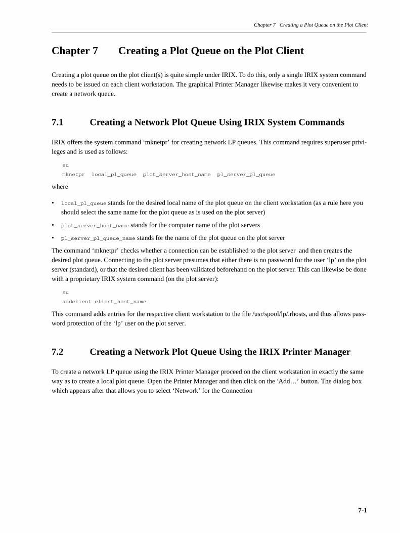
Chapter 7 Creating a Plot Queue on the Plot Client
Chapter 7 Creating a Plot Queue on the Plot Client
Creating a plot queue on the plot client(s) is quite simple under IRIX. To do this, only a single IRIX system command
needs to be issued on each client workstation. The graphical Printer Manager likewise makes it very convenient to
create a network queue.
7.1 Creating a Network Plot Queue Using IRIX System Commands
IRIX offers the system command ‘mknetpr’ for creating network LP queues. This command requires superuser privi-
leges and is used as follows:
su
mknetpr local_pl_queue plot_server_host_name pl_server_pl_queue
where
• local_pl_queue stands for the desired local name of the plot queue on the client workstation (as a rule here you
should select the same name for the plot queue as is used on the plot server)
• plot_server_host_name stands for the computer name of the plot servers
• pl_server_pl_queue_name stands for the name of the plot queue on the plot server
The command ‘mknetpr’ checks whether a connection can be established to the plot server and then creates the
desired plot queue. Connecting to the plot server presumes that either there is no password for the user ‘lp’ on the plot
server (standard), or that the desired client has been validated beforehand on the plot server. This can likewise be done
with a proprietary IRIX system command (on the plot server):
su
addclient client_host_name
This command adds entries for the respective client workstation to the file /usr/spool/lp/.rhosts, and thus allows pass-
word protection of the ‘lp’ user on the plot server.
7.2 Creating a Network Plot Queue Using the IRIX Printer Manager
To create a network LP queue using the IRIX Printer Manager proceed on the client workstation in exactly the same
way as to create a local plot queue. Open the Printer Manager and then click on the ‘Add…’ button. The dialog box
which appears after that allows you to select ‘Network’ for the Connection
7-1
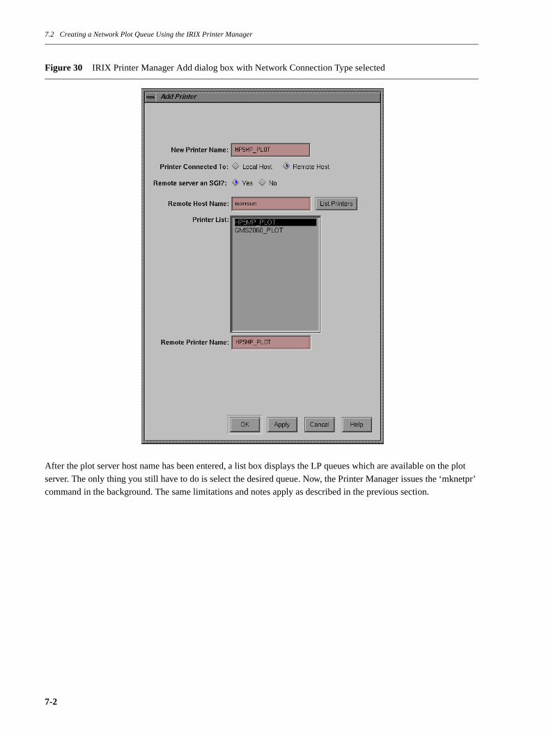
7.2 Creating a Network Plot Queue Using the IRIX Printer Manager
Figure 30 IRIX Printer Manager Add dialog box with Network Connection Type selected
After the plot server host name has been entered, a list box displays the LP queues which are available on the plot
server. The only thing you still have to do is select the desired queue. Now, the Printer Manager issues the ‘mknetpr’
command in the background. The same limitations and notes apply as described in the previous section.
7-2

Chapter 8 Removing a Plot Queue
Chapter 8 Removing a Plot Queue
It is also easy to remove a plot queue. Here too, IRIX offers a proprietary system command. And, this action can also
be performed using the IRIX Printer Manager.
8.1 Removing a Plot Queue Using IRIX System Commands
The system command is called ‘rmprinter’ and is used as follows:
su
rmprinter plot_queue_name
This command removes all AT&T LP spooler-proprietary administration entries, files, and directories which belong
to the given plot queue. This means that even the interface script file ‘plotface’, which might have been customized, is
removed from the directory /usr/spool/lp/interface. Thus it is very strongly recommended to save copies of the cus-
tomized ‘plotface’ files in the directory /usr/spool/lp/model!
Under no circumstances should you attempt to remove a plot queue in any other way than using the ‘rmprinter’ com-
mand. This could have a lasting effect on the function of the AT&T LP spooler.
8.2 Removing a Plot Queue Using the IRIX Printer Manager
It is extremely simple to remove a plot queue using the IRIX Printer Manager. Open the Printer Manager window,
then select the printer icon in question and click on the ‘Delete…’ button. Confirm the deletion by clicking ‘OK’.
Figure 31 IRIX Printer Manager Delete dialog box
8-1

Chapter 8 Removing a Plot Queue
8-2
Chapter 9 Customizing the Plot Server
Chapter 9 Customizing the Plot Server
The previous chapters showed that creating a plot queue copies the LP spooler interface file ‘plotface2.1’ into the
directory /usr/spool/lp/interface. In the process the file ‘plotface2.1’ is renamed with the given plot queue name. With
every plot request the LP spooler executes this interface file, which is provided with six parameters.
The task of the ‘plotface’ file is:
• to check the format of the file to be plotted. As was already mentioned, the allowed plot file formats are those of
the ICEM applications DDN, Surf, and Duct. If another format is passed to it, ‘plotface’ terminates prematurely
and writes an error entry into the log file ‘plotlog’ under /usr/spool/lp/request/plot_queue_name.
However, it is possible to specify that files of other formats be output unchanged (using dump) by assigning the
value ‘YES’ to the variable ‘dumpnoicem’ in the customizing area of ‘plotface2.1’.
• to convert the recognized ICEM plot file into the neutral Uniplot format NPFILE1 using the Uniplot preproces-sor specified for it.
• to check and evaluate the options passed on to the LP spooler.
• to convert the file ‘NPFILE’ into the appropriate plotter format (CAL907, HPGL etc.) on the basis of the speci-
fied variable values for customizing the format (see the following sub-section 9.1 “Customizing the Access Path of
the License File” on page 9-4) using the Uniplot postprocessor thus defined.
• to provide the ready-to-plot file with possible start and stop sequences.
• to output the ready-to-plot file, or, if so defined, to process it further and/or pass it on.
• to take care of diverse preliminary and finishing tasks which makes for the optimal use of the Uniplot post pro-
cessors.
• to make appropriate entries in its log file ‘plotlog’ for all processes.
The interface file plotface2.1’, whose listing is printed out in section 11.2 “Notes on the Operation of CalComp
CAL907 Output Devices” on page 11-4, has, roughly speaking, the following struture
1. Neutral Picture FILE.
9-1

Chapter 9 Customizing the Plot Server
Figure 32 Structure of the interface file ‘plotface’
Area in the file ‘plotlog’ is marked with the labels ‘START OF CUSTOMIZING AREA’ and ‘END OF CUSTOMIZ-
ING AREA’. The listing of the file ‘plotface2.1’ is printed out in section 11.8 “The LP Spooler Interface File
‘plotface2.1’” on page 11-21.
Customizing area
Here you will find variable assignments which you
should use to customize your system.
Commentary area
Here you will find notes on the installion and use of
‘plotface’.
Code area
As a rule this area remains unchanged. But even here there
are places prepared for special cases which can be custom-
ized and/or expanded.
9-2

Chapter 9 Customizing the Plot Server
Figure 33 Section of the customizing area of the file ‘plotface2.1’ (to be continued)
#-----------------------------------------------------------------------------#-----------------------------------------------------------------------------#- START OF CUSTOMIZING AREA -------------------------------------------------#-----------------------------------------------------------------------------#-----------------------------------------------------------------------------
# Information for the IRIX 5.x/6.x Printer Manager, don’t change!
# NAME=Plotface 2.1 Cal907# NAME=Plotface 2.1 HPGL# NAME=Plotface 2.1 HPGL/2# NAME=Plotface 2.1 PostScript
# Set the NAME variable below to 1 of the 4 values shown above,# filling the double quotes with 1 of the 4 strings shown above.# The NAME variable below will be set automatically by the Printer Manager,# if the IRIX Printer Manager is used to install the plot queue!
NAME="Plotface 2.1 HPGL"
#
TYPE="Plotface 2.1"
# License file variable, uncomment and adapt path if necessary
# LM_LICENSE_FILE=/icem/lic/license.dat; export LM_LICENSE_FILE
# Uniplot parameters <<<<<<<<<<<<<<<<<<<<<<<<<<<<<<<<<<<<<<<<<<<<<<<<<<<<<<<<<
# The ’if’-blocks below define, according to the value of the variable NAME,# the Uniplot device driver and keyword to be used. It might be necessary# to change manually the keyword definition to a value as described in the# ICEM PlotServer User and Administrator Manual.
if [ "$NAME" = "Plotface 2.1 Cal907" ]then
# Generic CalComp Cal907
dd=CAL907 # Device Driver d=CAL907 # Device-Keyword
9-3

9.1 Customizing the Access Path of the License File
Figure 34 Section of the customizing area of the file ’plotface2.1’ (continued)
You can see the entire listing of the ‘plotface2.1’ customizing area in section 11.8 “The LP Spooler Interface File
‘plotface2.1’” on page 11-21.
9.1 Customizing the Access Path of the License File
The AT&T LP spooling system runs independent of the users environment. That’s why the path and file name of the
license file must be specified in the customization area of the plotface interface script. Edit all plotface scripts in the
plot servers directory ~lp/interface and adapt the setting of the variable LM_LICENSE_FILE. See the bold line on
about half of figure 33.
9.2 Entering the Uniplot Postprocessor and Keyword
Obviously, the most important customization is entering the name of the Uniplot postprocessor and the keyword. This
is because they define what plotter format will be created. That is, whether CAL907, HPGL, HPGL/2 or PostScript
data should be generated.
Every Uniplot postprocessor possesses a series of keywords which influence how the Uniplot postprocessor creates
the plotter format. But, to jump ahead a little, only a few of the many keywords1 which Uniplot offers are really rele-
vant.
The selection of the Uniplot postprocessor and, thus, the plotter format to be created, is done in ‘plotface2.1’ by
assigning a specified text string to the variable ‘NAME’. This is done automatically if the the plot queue is defined
using the IRIX Printer Manager. If the plot queue was created on the shell level using the ‘lputil’ command, then the
variable ‘NAME’ must be manually assigned the value ‘Plotface 2.1 CAL907’, ‘Plotface 2.1 HPGL’, ‘Plotface 2.1
HPGL/2’ or ‘Plotface 2.1 PostScript’.
1. See section 11.7 “Notes about Uniplot Version 3.3 Release 01” on page 11-18.
# Cal907 parameters (Uniplot standard values): # Definition for the Generic CAL907 driver (dd=CAL907, d=CAL907): # Nr. of Pens, Steps/cm, Paper Length/Width, Sync/EOB-Codes and Checksum
nrpens=8 # Number of Pens steps=800 # Steps per cm plength=3600 # Paper Length in cm pwidth=86.4 # Paper Width in cm sync=94 # Double Sync Code with value 94 dez # A negative value will generate Single Sync eob=13 # End Of Block (EOB) Code with value 13 dez csum=N # Checksum (Y)es/(N)
inpdirs="$nrpens\n$steps\n$plength\n$pwidth\n$sync\n$eob\n$csum"
elif [ "$NAME" = "Plotface 2.1 Calpm" ]
9-4
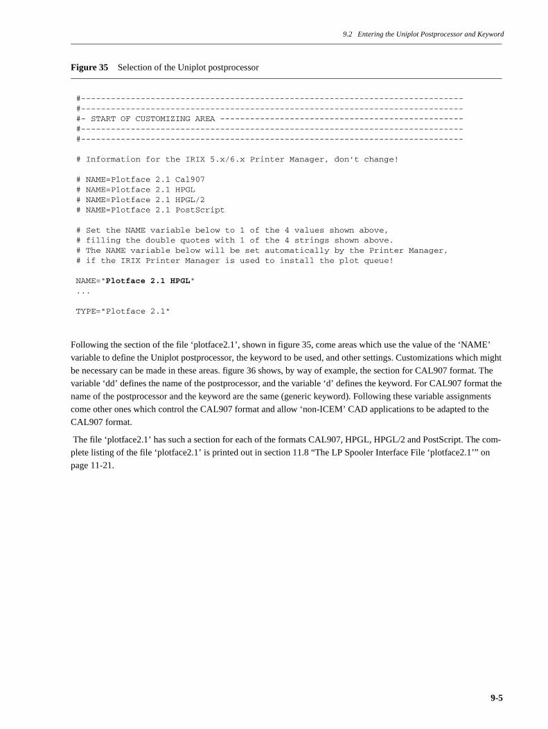
9.2 Entering the Uniplot Postprocessor and Keyword
Figure 35 Selection of the Uniplot postprocessor
Following the section of the file ‘plotface2.1’, shown in figure 35, come areas which use the value of the ‘NAME’
variable to define the Uniplot postprocessor, the keyword to be used, and other settings. Customizations which might
be necessary can be made in these areas. figure 36 shows, by way of example, the section for CAL907 format. The
variable ‘dd’ defines the name of the postprocessor, and the variable ‘d’ defines the keyword. For CAL907 format the
name of the postprocessor and the keyword are the same (generic keyword). Following these variable assignments
come other ones which control the CAL907 format and allow ‘non-ICEM’ CAD applications to be adapted to the
CAL907 format.
The file ‘plotface2.1’ has such a section for each of the formats CAL907, HPGL, HPGL/2 and PostScript. The com-
plete listing of the file ‘plotface2.1’ is printed out in section 11.8 “The LP Spooler Interface File ‘plotface2.1’” on
page 11-21.
#-----------------------------------------------------------------------------#-----------------------------------------------------------------------------#- START OF CUSTOMIZING AREA -------------------------------------------------#-----------------------------------------------------------------------------#-----------------------------------------------------------------------------
# Information for the IRIX 5.x/6.x Printer Manager, don’t change!
# NAME=Plotface 2.1 Cal907# NAME=Plotface 2.1 HPGL# NAME=Plotface 2.1 HPGL/2# NAME=Plotface 2.1 PostScript
# Set the NAME variable below to 1 of the 4 values shown above,# filling the double quotes with 1 of the 4 strings shown above.# The NAME variable below will be set automatically by the Printer Manager,# if the IRIX Printer Manager is used to install the plot queue!
NAME="Plotface 2.1 HPGL"...
TYPE="Plotface 2.1"
9-5
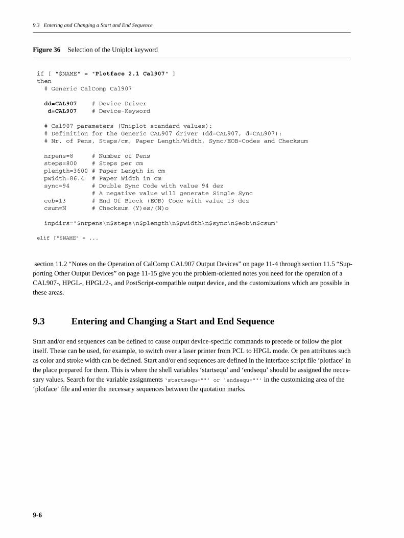
9.3 Entering and Changing a Start and End Sequence
Figure 36 Selection of the Uniplot keyword
section 11.2 “Notes on the Operation of CalComp CAL907 Output Devices” on page 11-4 through section 11.5 “Sup-
porting Other Output Devices” on page 11-15 give you the problem-oriented notes you need for the operation of a
CAL907-, HPGL-, HPGL/2-, and PostScript-compatible output device, and the customizations which are possible in
these areas.
9.3 Entering and Changing a Start and End Sequence
Start and/or end sequences can be defined to cause output device-specific commands to precede or follow the plot
itself. These can be used, for example, to switch over a laser printer from PCL to HPGL mode. Or pen attributes such
as color and stroke width can be defined. Start and/or end sequences are defined in the interface script file ‘plotface’ in
the place prepared for them. This is where the shell variables ‘startsequ’ and ‘endsequ’ should be assigned the neces-
sary values. Search for the variable assignments ‘startsequ=""’ or ‘endsequ=""’ in the customizing area of the
‘plotface’ file and enter the necessary sequences between the quotation marks.
if [ "$NAME" = "Plotface 2.1 Cal907" ]then # Generic CalComp Cal907
dd=CAL907 # Device Driver d=CAL907 # Device-Keyword
# Cal907 parameters (Uniplot standard values): # Definition for the Generic CAL907 driver (dd=CAL907, d=CAL907): # Nr. of Pens, Steps/cm, Paper Length/Width, Sync/EOB-Codes and Checksum
nrpens=8 # Number of Pens steps=800 # Steps per cm plength=3600 # Paper Length in cm pwidth=86.4 # Paper Width in cm sync=94 # Double Sync Code with value 94 dez # A negative value will generate Single Sync eob=13 # End Of Block (EOB) Code with value 13 dez csum=N # Checksum (Y)es/(N)o
inpdirs="$nrpens\n$steps\n$plength\n$pwidth\n$sync\n$eob\n$csum"
elif ["$NAME" = ...
9-6

9.3 Entering and Changing a Start and End Sequence
Figure 37 Definition of a start/end sequence
Here is an example of a start sequence for an HP-compatible laser printer with PCL escape sequences for switching
over to landscape format and HPGL/2 emulation:
startsequ="\033&l1O\033%0B"
The special character ‘escape’ is given in UNIX with octal notation ‘\033’. The same goes for almost all other non-
printing characters (ASCII codes less than decimal 32). The commands necessary in every particular case should be
obtained from the printer or plotter documentation.
Here is an example of a start sequence which, according to HPGL/2 syntax, defines plotter pen 1 to have stroke width
0.18 mm and color black:
startsequ="PW0.18,1;PC1,0,0,0;"
The ‘plotface’ file has pre-defined start and end sequences for HP-compatible laser printers and for the HP PaintJet
XL300, that is, for printers which should plot using HPGL emulation (HP 7475). They can be activated by assigning
the value ‘YES’ to one of the two prepared variables ‘hplj’ or ‘pjxl’. If additional commands are desired they can
be added in the respective ‘if’ block of the corresponding variables. The two ‘if’ blocks for checking the variables
‘hplj’ and ‘pjxl’ are located directly after the empty assignments for the variables ‘startsequ’ and ‘endsequ’ (see figure
37).
# Room for plotter specific start/end ’escape’ sequences
startsequ=""endsequ=""
if [ -n "$copies" ]then
# Assign code here which controls the multi copy feature of your plotter
startsequ=$startsequ"" endsequ=$endsequ""
fi
# Predefined sequences for the above mentioned laser printers
if [ "$hplj" = "YES" ] # HP Laserjet Laser printerthen startsequ=$startsequ"\033&l1O\033%0B" # landscape, HPGL/2 on endsequ=$endsequ"\033%0A\033E\033&l0O\014" # PCL mode, reset, portrait, fffiif [ "$pjxl" = "YES" ] # PaintJet XL300then startsequ=$startsequ"\033&l1O\033%-1BIN;" # landscape, HPGL/2 on, Init endsequ=$endsequ"\033%0A\033&l0O" # PCL mode, portraitfi
9-7

9.4 Changing the Default Uniplot Directives
9.4 Changing the Default Uniplot Directives
The Uniplot postprocessors can be controlled by a few small directives (scaling, rotation, etc.). The file ‘plotface2.1’
uses ‘SCALE=1’ as its standard directive, which reproduces the plot file true to scale. The ‘noscale’ option of the
‘lp’ options switch can temporarily change this directive to ‘DRAW=1’. This scales down the plot file to the plot area
size connected with the keyword. If, for example, this should be the standard setting, then this should be changed in
the customizing area of the ‘plotface’ file.
To do this use the editor to change the value of the variable ‘directive1’ from its present value of ‘SCALE=1\$’ to
‘DRAW=1\$’. The scaling factor can also be set to an arbitrary value (e.g., SCALE=0.5\$). Scaling which is different for
the X and Y axes, to compensate for plotter inaccuracies for example, can be attained with ‘SCALE=x-Factor,y-Fac-
tor\$’.
If more than one directive should be necessary, the additional directives should be assigned to the variable
‘directive2’. It appears useful to use this for the directive ‘ROTATE=ON*’, which permanently rotates the plot by 90×
counter clockwise. This directive can be temporarily set by using the ‘rot’ option of the ‘lp’ options switch.
Note
Uniplot directives must be separated by the character ‘*’. The last directive must end with the character ‘$’. The file
‘plotface’ creates the directives by concatenating the values of the two variables ‘directive2’ and ‘directive1’. This
explains the character combination ‘\$’ at the end of the value of the variable ‘directive1’ and the character ‘*’ at the
end of the value of the variable ‘directive2’. The ‘plotface’ file requires the backslash character ‘\’ in order to protect
the ‘$’ from being interpreted by the shell command ‘echo’, which is what writes the concatenated directive string
into a file (INPFILE) for the Uniplot postprocessor.
Figure 38 Uniplot standard directive(s)
9.5 Entering and Processing New Options
Entering new options certainly does not belong to the standard customizations which can be made in the ‘plotface’
file. However, ‘plotface’ makes their flexible expansion relatively simple.
As was already described on page 14, ‘plotface’ processes the options ‘ascale’, ‘noscale’, ‘rot’, and the sizes ‘a0 - a4’.
The options received from the ‘lp’ command are passed on to ‘plotface’ as positional parameter ‘$5’, which is a string.
The ‘plotface’ file sets the ‘options’ variable equal to this string. A Bourne shell ‘case’ statement checks the value of
the ‘options’ variable against known options, and performs the corresponding actions, usually by setting other vari-
ables.
Now it is very simple to insert new options to be checked into the case statement, and to handle them in the corre-
sponding manner. Figure 39 shows the section of the ‘plotface2.1’ file containing the case statement which was men-
tioned.
# Default directives <<<<<<<<<<<<<<<<<<<<<<<<<<<<<<<<<<<<<<<<<<<<<<<<<<<<<<<<< directive1="SCALE=1\$"directive2="NONE*" # any given Uniplot directive has to end with an ’*’
9-8

9.5 Entering and Processing New Options
Figure 39 ‘plotface’ options
Naturally, any new options which might be inserted, and the actions they perform must be reflected further on in the
‘plotface’ file.
#-----------------------------------------------------------------------------## Parse options specified with ’lp -o’ option##-----------------------------------------------------------------------------
for option in $optionsdo case $option in
noscale) directive1="SCALE=1\$" ;; NOSCALE) directive1="SCALE=1\$" ;; ascale) directive1="DRAW=1\$" ;; ASCALE) directive1="DRAW=1\$" ;; rot) directive2="ROTATE=ON*" ;; ROT) directive2="ROTATE=ON*" ;; a0) echo "$hpsizea0" > HPSIZE ;; A0) echo "$hpsizea0" > HPSIZE ;;
... ...
A4) echo "$hpsizea4" > HPSIZE ;; esacdone
9-9

9.6 Further Processing of Plot Files Created on the Hard Disk
9.6 Further Processing of Plot Files Created on the Hard Disk
The most common special customization in the ‘plotface’ file is further processing of plot files created on the hard
disk. This is because instead of directly outputting the ready-to-plot file to a physical interface, it is often desired to
make further manipulations in it, or to pass on the plot file in a completely different form. The following sections
show examples of how ‘plotface’ can be customized in a very targeted manner for a given problem. Figure 40 shows
the section of the file ‘plotface2.1’ which is to be changed by inserting any desired processing steps.
Figure 40 Processing of the ready-to-plot file 'PLOTF'
9.6.1 Manipulating Plot Files
You can find examples of the manipulation of the ready-to-plot file with the name ‘PLOTF’ in the ‘plotface’ file
itself. Thus, ‘plotface’ uses the Uniplot PostScript postprocessor to manipulate the stroke width in the PostScript code
of the file ‘PLOTF’ after it has been created.
Attaching start/end sequences, if they are defined, at the beginning or end of the file is another example of changing
the ready-to-plot file after it has been created.
The ‘/bin/cat ./PLOTF’ command shown inFigure 41 can be replaced by any Bourne shell command for manipulating
the ‘PLOTF’ file. Please note that all operations are executed with the user ID ‘lp’, since the interface script ‘plot-
face’ is executed by the AT&T LP spooling system under this user ID. This is especially important if you copy or
move the ‘PLOTF’ file. The corresponding actions must be permitted for the ‘user’ ‘lp’!
9.6.2 Transferring Plot Files to the BSD Spooling System
Especially in heterogeneous environments, that is, environments consisting of different computers internetworked
together and numerous application programs, the task of transferring a ready-to-plot file to another spooling system
often arises. The ICEM PlotServer Package then forms a type of gateway which creates the necessary plotter format
out of the ICEM plot files and then passes it on to existing print/plot queues in the network.
Transfer to the BSD spooling system is very often necessary, since it is available on practically all UNIX computers.
The BSD spooling system is even supported on the PC side. Naturally, transferring the ‘PLOTF’ file created by ‘plot-
face’ using the BSD spooling system’s ‘lpr’ command first requires the installation and configuration of the BSD
spooling system on the IRIX Plotserver Workstation.
#-----------------------------------------------------------------------------## Output or process the ready to plot plotfile PLOTF##-----------------------------------------------------------------------------
/bin/cat ./PLOTF # No redirection! The LP-Spooler does it for us!
# The above line may be replaced by any code processing the plotfile in # any different way (i.e. ftp, rcp, lpr it to another system).
# rm PLOTF # Remove or move the plot file. This is importantmv PLOTF plotf # due to the fact that Uniplot just opens the file # to write in without clearing it first!
9-10
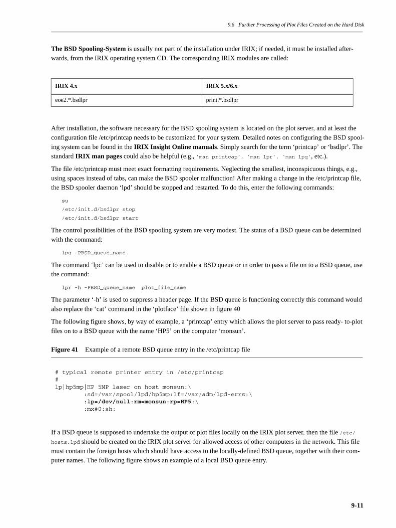
9.6 Further Processing of Plot Files Created on the Hard Disk
The BSD Spooling-System is usually not part of the installation under IRIX; if needed, it must be installed after-
wards, from the IRIX operating system CD. The corresponding IRIX modules are called:
After installation, the software necessary for the BSD spooling system is located on the plot server, and at least the
configuration file /etc/printcap needs to be customized for your system. Detailed notes on configuring the BSD spool-
ing system can be found in the IRIX Insight Online manuals. Simply search for the term ‘printcap’ or ‘bsdlpr’. The
standard IRIX man pages could also be helpful (e.g., ‘man printcap’, ‘man lpr’, ‘man lpq’, etc.).
The file /etc/printcap must meet exact formatting requirements. Neglecting the smallest, inconspicuous things, e.g.,
using spaces instead of tabs, can make the BSD spooler malfunction! After making a change in the /etc/printcap file,
the BSD spooler daemon ‘lpd’ should be stopped and restarted. To do this, enter the following commands:
su
/etc/init.d/bsdlpr stop
/etc/init.d/bsdlpr start
The control possibilities of the BSD spooling system are very modest. The status of a BSD queue can be determined
with the command:
lpq -PBSD_queue_name
The command ‘lpc’ can be used to disable or to enable a BSD queue or in order to pass a file on to a BSD queue, use
the command:
lpr -h -PBSD_queue_name plot_file_name
The parameter ‘-h’ is used to suppress a header page. If the BSD queue is functioning correctly this command would
also replace the ‘cat’ command in the ‘plotface’ file shown in figure 40
The following figure shows, by way of example, a ‘printcap’ entry which allows the plot server to pass ready- to-plot
files on to a BSD queue with the name ‘HP5’ on the computer ‘monsun’.
Figure 41 Example of a remote BSD queue entry in the /etc/printcap file
If a BSD queue is supposed to undertake the output of plot files locally on the IRIX plot server, then the file /etc/
hosts.lpd should be created on the IRIX plot server for allowed access of other computers in the network. This file
must contain the foreign hosts which should have access to the locally-defined BSD queue, together with their com-
puter names. The following figure shows an example of a local BSD queue entry.
IRIX 4.x IRIX 5.x/6.x
eoe2.*.bsdlpr print.*.bsdlpr
# typical remote printer entry in /etc/printcap#lp|hp5mp|HP 5MP laser on host monsun:\ :sd=/var/spool/lpd/hp5mp:lf=/var/adm/lpd-errs:\ :lp=/dev/null:rm=monsun:rp=HP5:\ :mx#0:sh:
9-11

9.7 Customizations to the Uniplot Postprocessors
Figure 42 Example of a local BSD queue entry in the /etc/printcap file
9.6.3 Sending Plot Files to an Output Device Connected via Ethernet
Modern Ethernet interfaces of printers or plotters, as a rule, have the ‘lpd’ protocol available, and therefore it is possi-
ble to address them with a BSD queue, as described in the previous section. The printer or plotter is then addressed
exactly like a remote BSD queue on another computer. It is important not to forget to enter the ‘hostname’ of the
printer or plotter, including its IP address, in the /etc/hosts file on the plot server. The ‘ping’ command should be used
to test the Ethernet connection to the output device before the BSD queue is defined on the plot server. Then, the
remaining steps correspond to those of the previous section.
Older Ethernet interfaces often require proprietary communications programs in order to send files from the plot
server to the printer or plotter. These programs are made available by the printer or plotter manufacturers either as
executable.
programs, or as source code. In the first case the binary program must naturally be compiled exactly for the operating
system, and in the second case it can be created on any platform, assuming it has a compiler, etc. The program to be
used should then be put in the ‘plotface’ file in the previously-described place (see figure 40), in order to send ready-
to-plot files to the output device over Ethernet.
9.6.4 Transferring Plot Files in Other Ways
It is also possible to transfer the ‘PLOTF’ file with the commands ‘cp’, ‘rcp’, ‘ftp’, and others. In so doing, keep in
mind that the user ‘lp’ must have permission to perform the desired operations. Before these actions are executed by
‘plotface’, you should run through them in the Bourne shell as user ‘lp’, e.g., by entering the command ‘su lp’ or
‘login lp’.
9.7 Customizations to the Uniplot Postprocessors
As has already been seen, the Uniplot postprocessors can be controlled to a certain extent by directives. More exten-
sive settings are concealed in the file ‘DHCFILE’1 or ‘DHCEXT’2 belonging to each postprocessor. These files con-
tain modifiable attributes for each postprocessor keyword, such as the number of pens, the resolution of the device,
the plotting surface, and other capabilities of the output device.
Except the new Uniplot postprocessor ‘HPGLU’, all others use one of the ‘DHCFILE’ binary files. The ‘HPGLU’
postprocessor takes its information from the ASCII file ‘DHCEXT’.
The following sections contain notes about how to change entries in the DHC files.
1. Device Hardware Characteristics FILE.2. Device Hardware Characteristics EXTended.
# typical local printer entry in /etc/printcap#lp|HP5|HP 5MP laser on /dev/plp:\ :sd=/var/spool/lpd/hp5mp:lf=/var/adm/lpd-errs:\ :lp=/dev/plp:mx#0:sh:
9-12
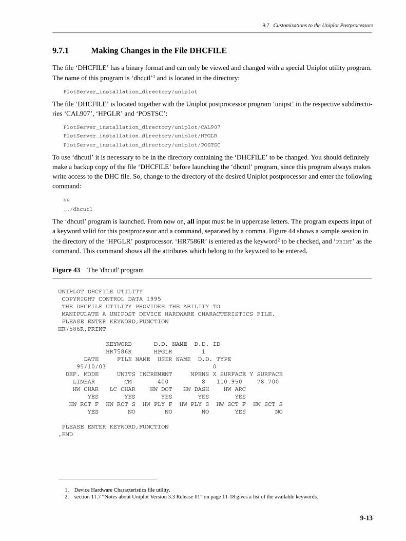
9.7 Customizations to the Uniplot Postprocessors
9.7.1 Making Changes in the File DHCFILE
The file ‘DHCFILE’ has a binary format and can only be viewed and changed with a special Uniplot utility program.
The name of this program is ‘dhcutl’1 and is located in the directory:
PlotServer_installation_directory/uniplot
The file ‘DHCFILE’ is located together with the Uniplot postprocessor program ‘unipst’ in the respective subdirecto-
ries ‘CAL907’, ‘HPGLR’ and ‘POSTSC’:
PlotServer_installation_directory/uniplot/CAL907
PlotServer_installation_directory/uniplot/HPGLR
PlotServer_installation_directory/uniplot/POSTSC
To use ‘dhcutl’ it is necessary to be in the directory containing the ‘DHCFILE’ to be changed. You should definitely
make a backup copy of the file ‘DHCFILE’ before launching the ‘dhcutl’ program, since this program always makes
write access to the DHC file. So, change to the directory of the desired Uniplot postprocessor and enter the following
command:
su
../dhcutl
The ‘dhcutl’ program is launched. From now on, all input must be in uppercase letters. The program expects input of
a keyword valid for this postprocessor and a command, separated by a comma. Figure 44 shows a sample session in
the directory of the ‘HPGLR’ postprocessor. ‘HR7586R’ is entered as the keyword2 to be checked, and ‘PRINT’ as the
command. This command shows all the attributes which belong to the keyword to be entered.
Figure 43 The 'dhcutl' program
1. Device Hardware Characteristics file utility.2. section 11.7 “Notes about Uniplot Version 3.3 Release 01” on page 11-18 gives a list of the available keywords.
UNIPLOT DHCFILE UTILITY COPYRIGHT CONTROL DATA 1995 THE DHCFILE UTILITY PROVIDES THE ABILITY TO MANIPULATE A UNIPOST DEVICE HARDWARE CHARACTERISTICS FILE. PLEASE ENTER KEYWORD,FUNCTIONHR7586R,PRINT
KEYWORD D.D. NAME D.D. ID HR7586R HPGLR 1 DATE FILE NAME USER NAME D.D. TYPE 95/10/03 0 DEF. MODE UNITS INCREMENT NPENS X SURFACE Y SURFACE LINEAR CM 400 8 110.950 78.700 HW CHAR LC CHAR HW DOT HW DASH HW ARC YES YES YES YES YES HW RCT F HW RCT S HW PLY F HW PLY S HW SCT F HW SCT S YES NO NO NO YES NO
PLEASE ENTER KEYWORD,FUNCTION,END
9-13

9.7 Customizations to the Uniplot Postprocessors
Entering ‘HR7586R,MODIFY’ allows one or several attributes to be changed. After a ‘MODIFY’ command has been
issued, the program will ask about all attributes in the series, for which reason it is strongly advised to display them
with the ‘PRINT’ command, in order that the correct answers can be entered. In the above example, when the program
asks about the number of pens (NPENS), 16 can be entered instead of 8, in order to take advantage of the capabilities
of a modern HPGL plotter.
A new keyword can also be entered into the DHC file with the ‘INSERT’ command.
To quit out of the ‘dhcutl’ program use the command ‘END’1.
The change will become effective the next time the Uniplot postprocessor is run with this keyword.
The ‘DHCFILE’ cannot be imported from older versions of Uniplot. Changes which might have been made must be
made again in a newer version of Uniplot using the ‘dhcutl’ program.
9.7.2 Making Changes in the File DHCEXT
The file ‘DHCEXT’ with its new ASCII format no longer has the shortcomings of the binary file ‘DHCFILE’. How-
ever, this new format is currently only supported by the Uniplot ‘HPGLU’ postprocessor. The file ‘DHCEXT’ does
not require any program to manipulate it, but rather can be viewed and changed using an editor. Figure 44 shows an
excerpt of the file ‘DHCEXT’. The original file contains notes at the beginning concerning the meaning of the individ-
ual values.
1. That is, no keyword, but only ‘,’ and ‘END’.
9-14
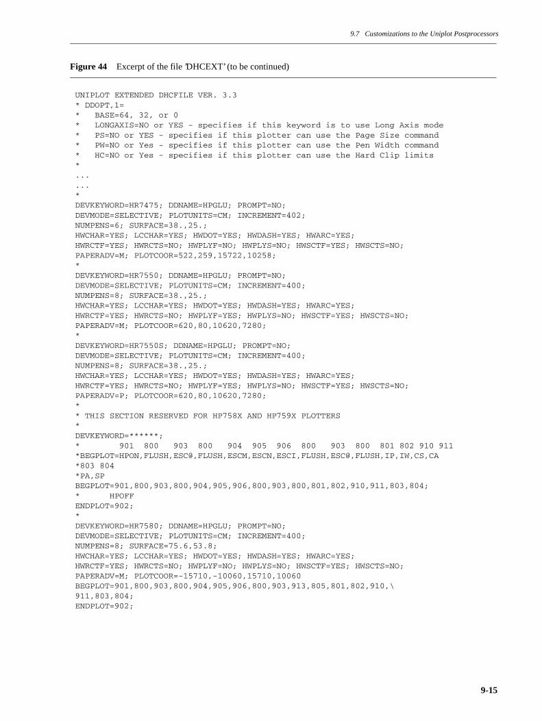
9.7 Customizations to the Uniplot Postprocessors
Figure 44 Excerpt of the file ’DHCEXT’ (to be continued)
UNIPLOT EXTENDED DHCFILE VER. 3.3* DDOPT,1=* BASE=64, 32, or 0* LONGAXIS=NO or YES - specifies if this keyword is to use Long Axis mode* PS=NO or YES - specifies if this plotter can use the Page Size command* PW=NO or Yes - specifies if this plotter can use the Pen Width command* HC=NO or Yes - specifies if this plotter can use the Hard Clip limits*......*DEVKEYWORD=HR7475; DDNAME=HPGLU; PROMPT=NO;DEVMODE=SELECTIVE; PLOTUNITS=CM; INCREMENT=402;NUMPENS=6; SURFACE=38.,25.;HWCHAR=YES; LCCHAR=YES; HWDOT=YES; HWDASH=YES; HWARC=YES;HWRCTF=YES; HWRCTS=NO; HWPLYF=NO; HWPLYS=NO; HWSCTF=YES; HWSCTS=NO;PAPERADV=M; PLOTCOOR=522,259,15722,10258;*DEVKEYWORD=HR7550; DDNAME=HPGLU; PROMPT=NO;DEVMODE=SELECTIVE; PLOTUNITS=CM; INCREMENT=400;NUMPENS=8; SURFACE=38.,25.;HWCHAR=YES; LCCHAR=YES; HWDOT=YES; HWDASH=YES; HWARC=YES;HWRCTF=YES; HWRCTS=NO; HWPLYF=YES; HWPLYS=NO; HWSCTF=YES; HWSCTS=NO;PAPERADV=M; PLOTCOOR=620,80,10620,7280;*DEVKEYWORD=HR7550S; DDNAME=HPGLU; PROMPT=NO;DEVMODE=SELECTIVE; PLOTUNITS=CM; INCREMENT=400;NUMPENS=8; SURFACE=38.,25.;HWCHAR=YES; LCCHAR=YES; HWDOT=YES; HWDASH=YES; HWARC=YES;HWRCTF=YES; HWRCTS=NO; HWPLYF=YES; HWPLYS=NO; HWSCTF=YES; HWSCTS=NO;PAPERADV=P; PLOTCOOR=620,80,10620,7280;** THIS SECTION RESERVED FOR HP758X AND HP759X PLOTTERS*DEVKEYWORD=******;* 901 800 903 800 904 905 906 800 903 800 801 802 910 911*BEGPLOT=HPON,FLUSH,ESC@,FLUSH,ESCM,ESCN,ESCI,FLUSH,ESC@,FLUSH,IP,IW,CS,CA*803 804*PA,SPBEGPLOT=901,800,903,800,904,905,906,800,903,800,801,802,910,911,803,804;* HPOFFENDPLOT=902;*DEVKEYWORD=HR7580; DDNAME=HPGLU; PROMPT=NO;DEVMODE=SELECTIVE; PLOTUNITS=CM; INCREMENT=400;NUMPENS=8; SURFACE=75.6,53.8;HWCHAR=YES; LCCHAR=YES; HWDOT=YES; HWDASH=YES; HWARC=YES;HWRCTF=YES; HWRCTS=NO; HWPLYF=NO; HWPLYS=NO; HWSCTF=YES; HWSCTS=NO;PAPERADV=M; PLOTCOOR=-15710,-10060,15710,10060BEGPLOT=901,800,903,800,904,905,906,800,903,913,805,801,802,910,\911,803,804;ENDPLOT=902;
9-15

9.7 Customizations to the Uniplot Postprocessors
Figure 45 Excerpt of the file ’DHCEXT’ (continued)
*DEVKEYWORD=HR7585; DDNAME=HPGLU; PROMPT=NO;DEVMODE=SELECTIVE; PLOTUNITS=CM; INCREMENT=400;NUMPENS=8; SURFACE=110.95,78.7;HWCHAR=YES; LCCHAR=YES; HWDOT=YES; HWDASH=YES; HWARC=YES;HWRCTF=YES; HWRCTS=NO; HWPLYF=NO; HWPLYS=NO; HWSCTF=YES; HWSCTS=NO;PAPERADV=M; PLOTCOOR=-20840,-16180,20840,16180;*
9-16
Chapter 10 Diagnosing and Correcting Plotting Problems
Chapter 10 Diagnosing and Correcting Plotting Problems
The standard AT&T spooling system, which is used by the ICEM PlotServer Package, along with additional diagnos-
tic aids such as a log file and a diagnostic script, offer a good basis for identifying and correcting the cause of plotting
problems quickly and surely.
When searching for the cause of plotting problems, you should proceed in the order of the following sub-chapters. If
these aids do not bring any improvement, the error must have to do either with the transmission medium to the output
device (cable, physical interface, network), or the output device itself (incorrect settings or physical defect).
10.1 The Log File ‘plotlog’ on the Plot Server
The first place to start when searching for the cause of a plotting problem should be to check the ASCII log file ‘plot-
log’. This log file is located on the plot server (and only there) in the ‘request’ directory of the corresponding plot
queue (that is, of an LP queue which uses the ‘plotface’ file as its interface script file). That is, generally speaking in
the directory:
/usr/spool/lp/request/plot_queue_name
The ‘plotlog’ file always contains the log entries of the last plotting run (that is, it is always overwritten). These
entries are made by the interface script file ‘plotface’ and reflect the progress of the diverse plot file conversions. Sim-
ple errors, such as, Uniplot preprocessors and postprocessors which are not (or are no longer) accessible because of
changed path names, etc., can thus be easily detected. In its various sections the ‘plotlog’ file shows the progress of
the sequence of plotting events and possible errors.
If the log file contains no current entries (date and time of the plot request), this shows that the interface script ‘plot-
face’ did not run on the plot server. This could be the cause of a malfunction of the spooling system of the plot server
or the client. The two next sections give procedures which can correct problems of the spooling system, among other
things.
10-1

10.1 The Log File ‘plotlog’ on the Plot Server
Figure 46 Log file ‘plotlog’
========================================================================
PLOT LOGFILE of ’plotface’ revision 2.1
========================================================================Date of plot:____________ Mon Jan 11 14:21:56 PST 1999Plotdevice:______________ QMSplotPlot Port:_______________ /dev/plpUsername:________________ wkuPlotfile:________________ /usr/spool/lp/request/QMSplot/d0-2165LP-ID:___________________ QMSplot-2165Options:_________________ rot ascale========================================================================The plotfile is already a Uniplot NPFILE ...========================================================================Content of ’INPFILE’:007.8711.3ROTATE=ON*DRAW=1$========================================================================Content of ’OPFILE’:INPFILE/dev/ttyNPFILEPLOTFPSLINECMOFFLINENOwkuDHCFILE ========================================================================-rw-r--r-- 1 lp lp 1804 Jan 11 14:21 DHCFILE-rw-rw-rw- 1 lp lp 33 Jan 11 14:21 INPFILE-rw-rw-r-- 1 lp lp 960 Jan 11 14:21 NPFILE-rw-rw-rw- 1 lp lp 67 Jan 11 14:21 OPFILE======================================================================== UNIPOST V3.3 RELEASE 01 COPYRIGHT CONTROL DATA 1995 PRINTER IMAGEABLE REGION IN INCHES: ENTER THE LOWER LEFT X BOUNDARY. ENTER THE LOWER LEFT Y BOUNDARY. ENTER THE UPPER RIGHT X BOUNDARY. ENTER THE UPPER RIGHT Y BOUNDARY. ROTATE=ON* DRAW=1$ THE FOLLOWING ERRORS WERE ENCOUNTERED - **UMI615 AUTOMATIC SCALING HAS OCCURRED INFORMATIVE ========================================================================End of Plot Protocol ...========================================================================
10-2

10.2 The Diagnostic Script ‘tst_plotter’ on the Plot Server
Figure 46 shows the content of a ‘plotlog’ file of a successful plot output on a PostScript laser printer.When using
ICEMview the log file ‘plotlog’ can be displayed in an elegant manner by performing an ‘ALT-OPEN’, that is by dou-
ble-clicking on the corresponding plotter icon while simultaneously holding down the ALT key. If this action is per-
formed on a client workstation, the corresponding log file is automatically accessed on the plot server. Thus, it is not
necessary to be on the plot server.
10.2 The Diagnostic Script ‘tst_plotter’ on the Plot Server
If the log file ‘plotlog’ gives no indication of the cause of the error, the second step should be to execute the diagnostic
script ‘tst_plotter’. The way to launch this script and the way it functions were described in detail in Chapter 6 “Test-
ing a Plot Queue on the Plot Server” on page 6-1.
The diagnostic script can reliably identify errors in the plot server’s spooling system, among others. The next section
explains how to restart the LP spooling system without rebooting the workstation.
10.3 Restarting the LP Spooler without Rebooting
If the LP spooling system no longer functions as usual, it often helps to restart it. Typical errors of the spooling system
which, as a rule, can be corrected by a restart include:
• Hanging plotting requests
• Plotting jobs not appearing in the plot queue
• Plotting jobs not being processed
It is usually enough to stop the spooling system with the appropriate system commands and to restart it. It is often not
possible to reboot the workstation just like that, especially with plot servers which also serve as NFS file servers.
Any plot requests which might be hanging should be removed from the LP queue using the ‘cancel’ command before
the spooling system is restarted.
To stop the spooling system, execute the following command with superuser privileges:
su
/etc/init.d/lp stop
After that, restart the spooling system as follows:
/etc/init.d/lp start
This sequence of commands is automatically executed when the workstation is rebooted and restarted (through the
symbolic links /etc/rc2.d/S60lp and /etc/rc0.d/K25lp).
However, if the malfunction of the spooling system should have to do with deadlocked serial ports, rebooting the
workstation is unavoidable.
It can happen that the LP spooling system has disabled an LP queue. Such a disabled queue can be re-enabled with the
‘enable’ command:
su
enable LP-queue_name
10-3

10.3 Restarting the LP Spooler without Rebooting
10-4

Chapter 11 Information on Output Devices and the Uniplot Software
Chapter 11 Information on Output Devices and the Uniplot Software
11.1 Notes on the Operation of the PlotServer Package on AIX
The implementation and usage of the ICEM PlotServer Package for AIX differs from the other supported UNIX plat-
forms. AIX uses a spooling system similar to the BSD spooling system. There is no option to use additionally an
AT&T compatible spooling system. To still keep full functionality of the plotface interface script, a normal script
based on plotface was created. This script is named ‘pll‘ (plot locally). Plot clients use a script similar to netface
named ‘plr‘ (plot remotely). After the installation of the ICEM PlotServer Package both scripts are located in the
installation directory. The usage of the scripts is identical to the lp-command. Both scripts should be customized and
copied in to a directory on the plot server beeing part of the user’s search path (i.e. /usr/bin). The plot client requires to
customize and copy the script ‘plr’ only.
The possible and necessary changes to both scripts ‘pll‘ and ‘plr‘ are well documented in the scripts and correspond to
the customizations of plotface.
11-1
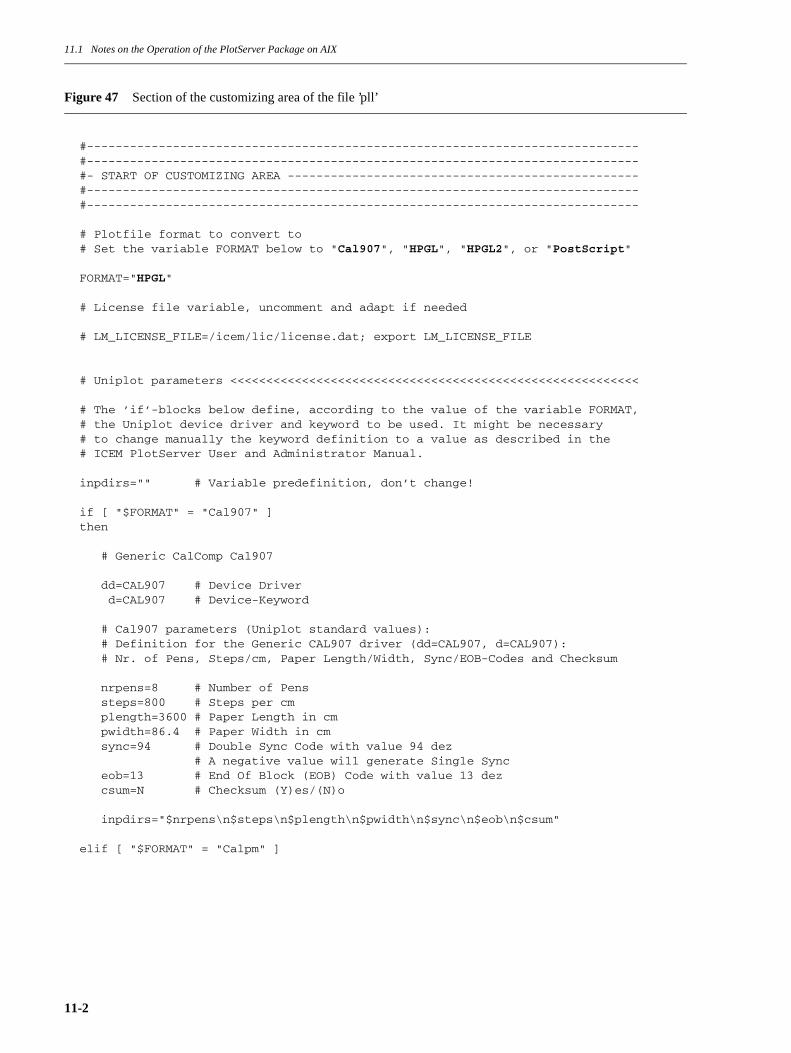
11.1 Notes on the Operation of the PlotServer Package on AIX
Figure 47 Section of the customizing area of the file ’pll’
#-----------------------------------------------------------------------------#-----------------------------------------------------------------------------#- START OF CUSTOMIZING AREA -------------------------------------------------#-----------------------------------------------------------------------------#-----------------------------------------------------------------------------
# Plotfile format to convert to# Set the variable FORMAT below to "Cal907", "HPGL", "HPGL2", or "PostScript"
FORMAT="HPGL"
# License file variable, uncomment and adapt if needed
# LM_LICENSE_FILE=/icem/lic/license.dat; export LM_LICENSE_FILE
# Uniplot parameters <<<<<<<<<<<<<<<<<<<<<<<<<<<<<<<<<<<<<<<<<<<<<<<<<<<<<<<<<
# The ’if’-blocks below define, according to the value of the variable FORMAT,# the Uniplot device driver and keyword to be used. It might be necessary# to change manually the keyword definition to a value as described in the# ICEM PlotServer User and Administrator Manual.
inpdirs="" # Variable predefinition, don’t change!
if [ "$FORMAT" = "Cal907" ]then
# Generic CalComp Cal907
dd=CAL907 # Device Driver d=CAL907 # Device-Keyword
# Cal907 parameters (Uniplot standard values): # Definition for the Generic CAL907 driver (dd=CAL907, d=CAL907): # Nr. of Pens, Steps/cm, Paper Length/Width, Sync/EOB-Codes and Checksum
nrpens=8 # Number of Pens steps=800 # Steps per cm plength=3600 # Paper Length in cm pwidth=86.4 # Paper Width in cm sync=94 # Double Sync Code with value 94 dez # A negative value will generate Single Sync eob=13 # End Of Block (EOB) Code with value 13 dez csum=N # Checksum (Y)es/(N)o
inpdirs="$nrpens\n$steps\n$plength\n$pwidth\n$sync\n$eob\n$csum"
elif [ "$FORMAT" = "Calpm" ]
11-2

11.1 Notes on the Operation of the PlotServer Package on AIX
Figure 48 Customizing area of the file ’plr’
The script ‘pll’ creates by usage of the ICEM PlotServer Package the ready to plot plot file. This file is either sent to
the spooling system using a dumb queue or copied in to the directory /tmp giving it a unique name. The next figure
shows the customizable area for this issue in the script ‘pll‘.
Figure 49 Customizing plot file handling in the file ‘pll‘
On principle the pair of both scripts ‘plr‘ and ‘pll‘ could also be used on any other supported UNIX platform.
#-----------------------------------------------------------------------------#-----------------------------------------------------------------------------#- START OF CUSTOMIZING AREA -------------------------------------------------#-----------------------------------------------------------------------------#-----------------------------------------------------------------------------
# Hostname of the ICEM PlotServer workstation
plotserver=""
# User account to use for rcp and rsh command
ruser=guest
#-----------------------------------------------------------------------------#-----------------------------------------------------------------------------#- END OF CUSTOMIZING AREA ---------------------------------------------------#-----------------------------------------------------------------------------#-----------------------------------------------------------------------------
#-----------------------------------------------------------------------------## Output or process the ready to plot plotfile PLOTF##-----------------------------------------------------------------------------
if [ -n "$device" -a -x /usr/bsd/lpr ]then # Forward the ready to plot plotfile to the dumb queue $device using lpr /usr/bsd/lpr -P$device -h PLOTFelse # Just move the ready to plot plotfile to /tmp with a unique naming scheme chmod 644 PLOTF mv PLOTF /tmp/${FORMAT}_$$fi
# The above lines may be replaced by any code processing the plotfile in # any different way (i.e. ftp, rcp).
11-3
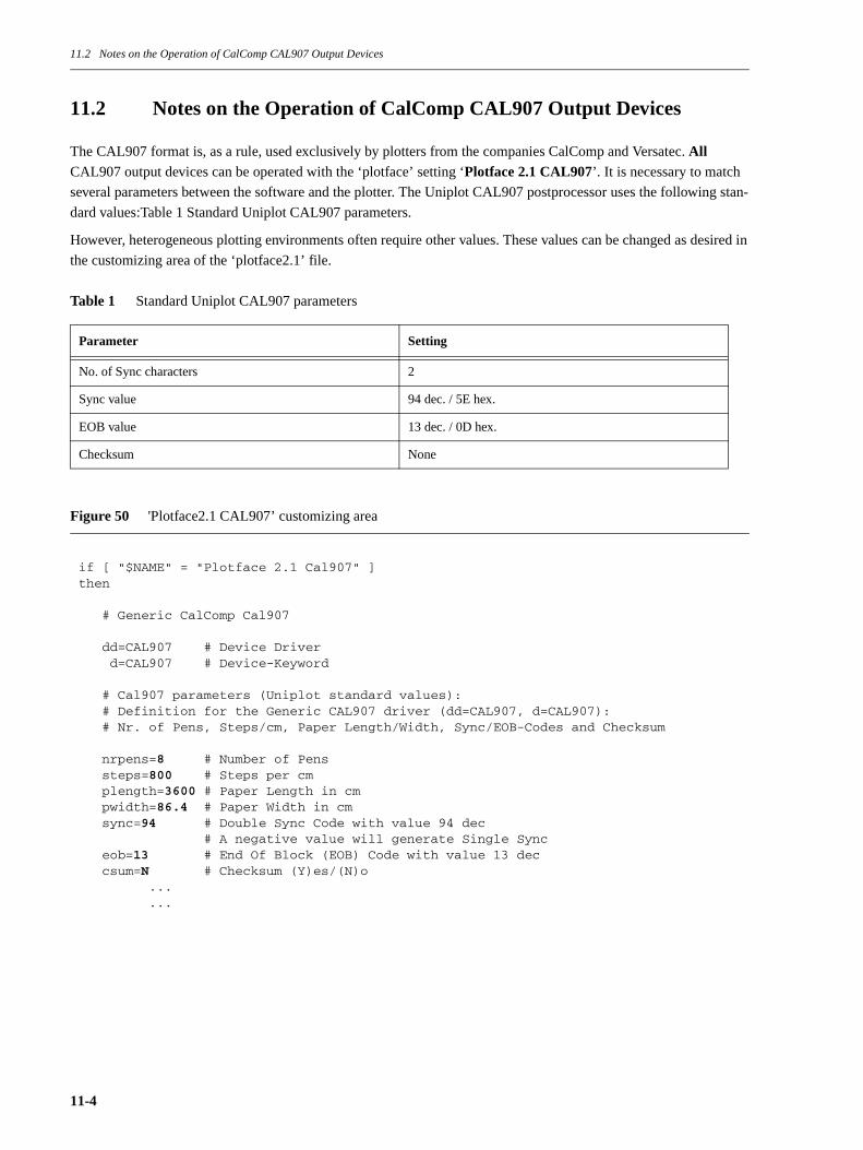
11.2 Notes on the Operation of CalComp CAL907 Output Devices
11.2 Notes on the Operation of CalComp CAL907 Output Devices
The CAL907 format is, as a rule, used exclusively by plotters from the companies CalComp and Versatec. All CAL907 output devices can be operated with the ‘plotface’ setting ‘Plotface 2.1 CAL907’. It is necessary to match
several parameters between the software and the plotter. The Uniplot CAL907 postprocessor uses the following stan-
dard values:Table 1 Standard Uniplot CAL907 parameters.
However, heterogeneous plotting environments often require other values. These values can be changed as desired in
the customizing area of the ‘plotface2.1’ file.
Table 1 Standard Uniplot CAL907 parameters
Figure 50 'Plotface2.1 CAL907’ customizing area
Parameter Setting
No. of Sync characters 2
Sync value 94 dec. / 5E hex.
EOB value 13 dec. / 0D hex.
Checksum None
if [ "$NAME" = "Plotface 2.1 Cal907" ]then # Generic CalComp Cal907 dd=CAL907 # Device Driver d=CAL907 # Device-Keyword # Cal907 parameters (Uniplot standard values): # Definition for the Generic CAL907 driver (dd=CAL907, d=CAL907): # Nr. of Pens, Steps/cm, Paper Length/Width, Sync/EOB-Codes and Checksum nrpens=8 # Number of Pens steps=800 # Steps per cm plength=3600 # Paper Length in cm pwidth=86.4 # Paper Width in cm sync=94 # Double Sync Code with value 94 dec # A negative value will generate Single Sync eob=13 # End Of Block (EOB) Code with value 13 dec csum=N # Checksum (Y)es/(N)o ... ...
11-4
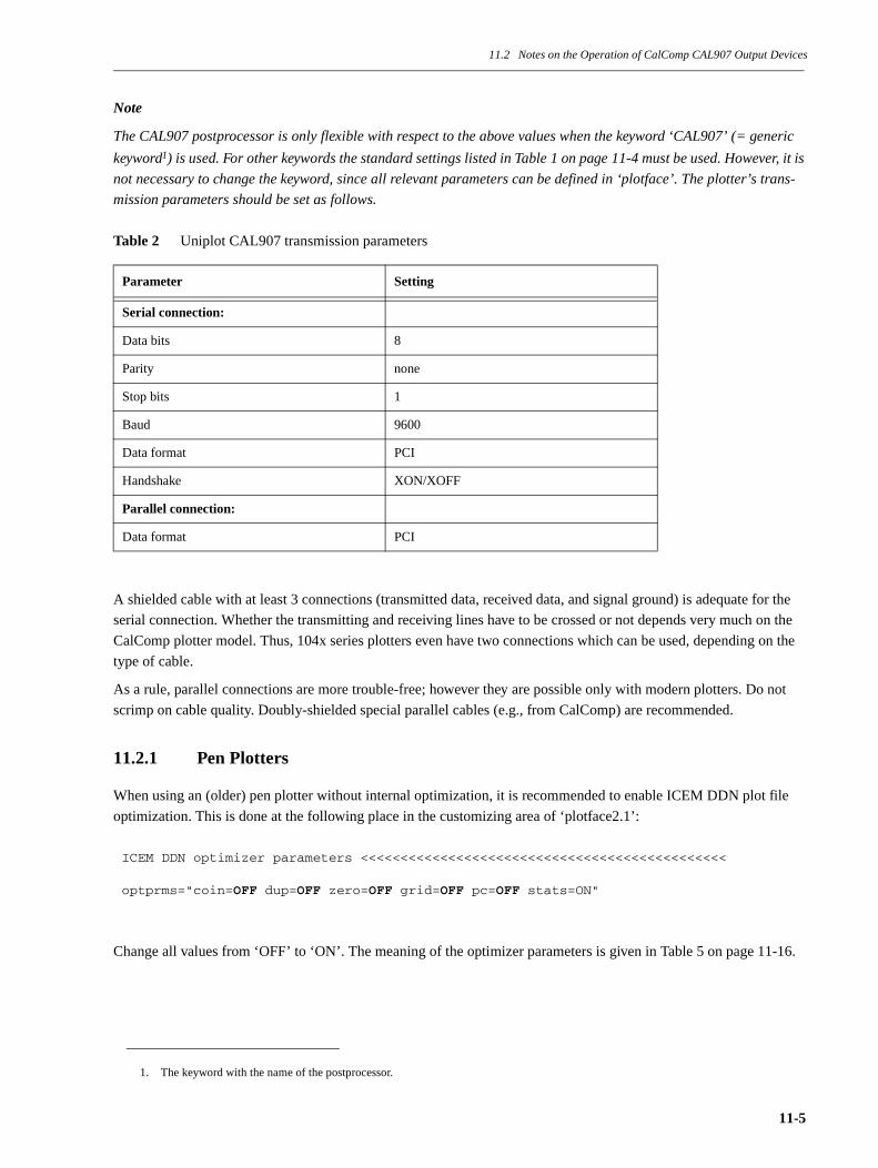
11.2 Notes on the Operation of CalComp CAL907 Output Devices
Note
The CAL907 postprocessor is only flexible with respect to the above values when the keyword ‘CAL907’ (= generic
keyword1) is used. For other keywords the standard settings listed in Table 1 on page 11-4 must be used. However, it is
not necessary to change the keyword, since all relevant parameters can be defined in ‘plotface’. The plotter’s trans-
mission parameters should be set as follows.
Table 2 Uniplot CAL907 transmission parameters
A shielded cable with at least 3 connections (transmitted data, received data, and signal ground) is adequate for the
serial connection. Whether the transmitting and receiving lines have to be crossed or not depends very much on the
CalComp plotter model. Thus, 104x series plotters even have two connections which can be used, depending on the
type of cable.
As a rule, parallel connections are more trouble-free; however they are possible only with modern plotters. Do not
scrimp on cable quality. Doubly-shielded special parallel cables (e.g., from CalComp) are recommended.
11.2.1 Pen Plotters
When using an (older) pen plotter without internal optimization, it is recommended to enable ICEM DDN plot file
optimization. This is done at the following place in the customizing area of ‘plotface2.1’:
Change all values from ‘OFF’ to ‘ON’. The meaning of the optimizer parameters is given in Table 5 on page 11-16.
1. The keyword with the name of the postprocessor.
Parameter Setting
Serial connection:
Data bits 8
Parity none
Stop bits 1
Baud 9600
Data format PCI
Handshake XON/XOFF
Parallel connection:
Data format PCI
ICEM DDN optimizer parameters <<<<<<<<<<<<<<<<<<<<<<<<<<<<<<<<<<<<<<<<<<<<<< optprms="coin=OFF dup=OFF zero=OFF grid=OFF pc=OFF stats=ON"
11-5

11.2 Notes on the Operation of CalComp CAL907 Output Devices
11.2.2 Raster Plotters (Laser, Ink Jet, Thermal, Electrostatic)
Raster plotters have been more successful than pen plotters due to their clear advantages, such as high output speed
and low operating noise. Modern devices such as the CalComp CCL600 laser printer, the CalComp Drawing Master
thermal plotter, the CalComp Solus laser plotter, as well as the CalComp Techjet ink jet plotter even have emulation
recognition, which makes customization of the CAL907 parameters (see Table 1 on page 11-4) unnecessary, and often
even allows the output of HPGL files.
11.2.3 Using CDCL (CalComp Device Control Language)
CDCL can be used to make extensive plotter settings using software. These CDCL commands can be integrated with-
out problems into the start sequence prepared by ‘plotface’. Thus, for example, implementing the capability of pro-
ducing multiple plots in a CalComp Drawing Master is very elegant. The CDCL commands simply have to be added
to the ‘plotface’ file and then the ‘lp’ option ‘-nnumber’ can be used. The ‘plotface’ file has the number available in
the variable ‘$copies’, which can be passed as an argument to the CDCL command ‘COPIES()’. The bold part of fig-
ure 51, page 11-6 shows what must be added to the ‘plotface’ file.
Figure 51 Example of the use of CDCL commands
# Room for plotter specific start/end ’escape’ sequences
startsequ=""endsequ=""
#-----------------------------------------------------------------------------# Multi copy feature per Calcomp CDCL#copies=$4
if [ -n "$copies" ]then sq="&&&&CALCOMP DEVICE CONTROL\n" sq=$sq"COPIES($copies)\n" startsequ=$sq"^^^^END OF FILE\n"fi#-----------------------------------------------------------------------------
11-6
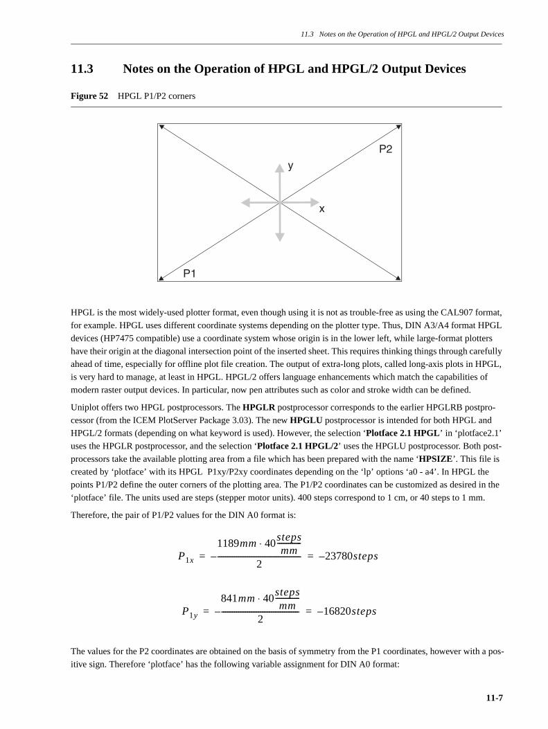
11.3 Notes on the Operation of HPGL and HPGL/2 Output Devices
11.3 Notes on the Operation of HPGL and HPGL/2 Output Devices
Figure 52 HPGL P1/P2 corners
HPGL is the most widely-used plotter format, even though using it is not as trouble-free as using the CAL907 format,
for example. HPGL uses different coordinate systems depending on the plotter type. Thus, DIN A3/A4 format HPGL
devices (HP7475 compatible) use a coordinate system whose origin is in the lower left, while large-format plotters
have their origin at the diagonal intersection point of the inserted sheet. This requires thinking things through carefully
ahead of time, especially for offline plot file creation. The output of extra-long plots, called long-axis plots in HPGL,
is very hard to manage, at least in HPGL. HPGL/2 offers language enhancements which match the capabilities of
modern raster output devices. In particular, now pen attributes such as color and stroke width can be defined.
Uniplot offers two HPGL postprocessors. The HPGLR postprocessor corresponds to the earlier HPGLRB postpro-
cessor (from the ICEM PlotServer Package 3.03). The new HPGLU postprocessor is intended for both HPGL and
HPGL/2 formats (depending on what keyword is used). However, the selection ‘Plotface 2.1 HPGL’ in ‘plotface2.1’
uses the HPGLR postprocessor, and the selection ‘Plotface 2.1 HPGL/2’ uses the HPGLU postprocessor. Both post-
processors take the available plotting area from a file which has been prepared with the name ‘HPSIZE’. This file is
created by ‘plotface’ with its HPGL P1xy/P2xy coordinates depending on the ‘lp’ options ‘a0 - a4’. In HPGL the
points P1/P2 define the outer corners of the plotting area. The P1/P2 coordinates can be customized as desired in the
‘plotface’ file. The units used are steps (stepper motor units). 400 steps correspond to 1 cm, or 40 steps to 1 mm.
Therefore, the pair of P1/P2 values for the DIN A0 format is:
The values for the P2 coordinates are obtained on the basis of symmetry from the P1 coordinates, however with a pos-
itive sign. Therefore ‘plotface’ has the following variable assignment for DIN A0 format:
x
y
P2
P1
P1x
1189mm 40stepsmm
-------------⋅
2---------------------------------------------– 23780steps–= =
P1y
841mm 40stepsmm
-------------⋅
2------------------------------------------– 16820steps–= =
11-7
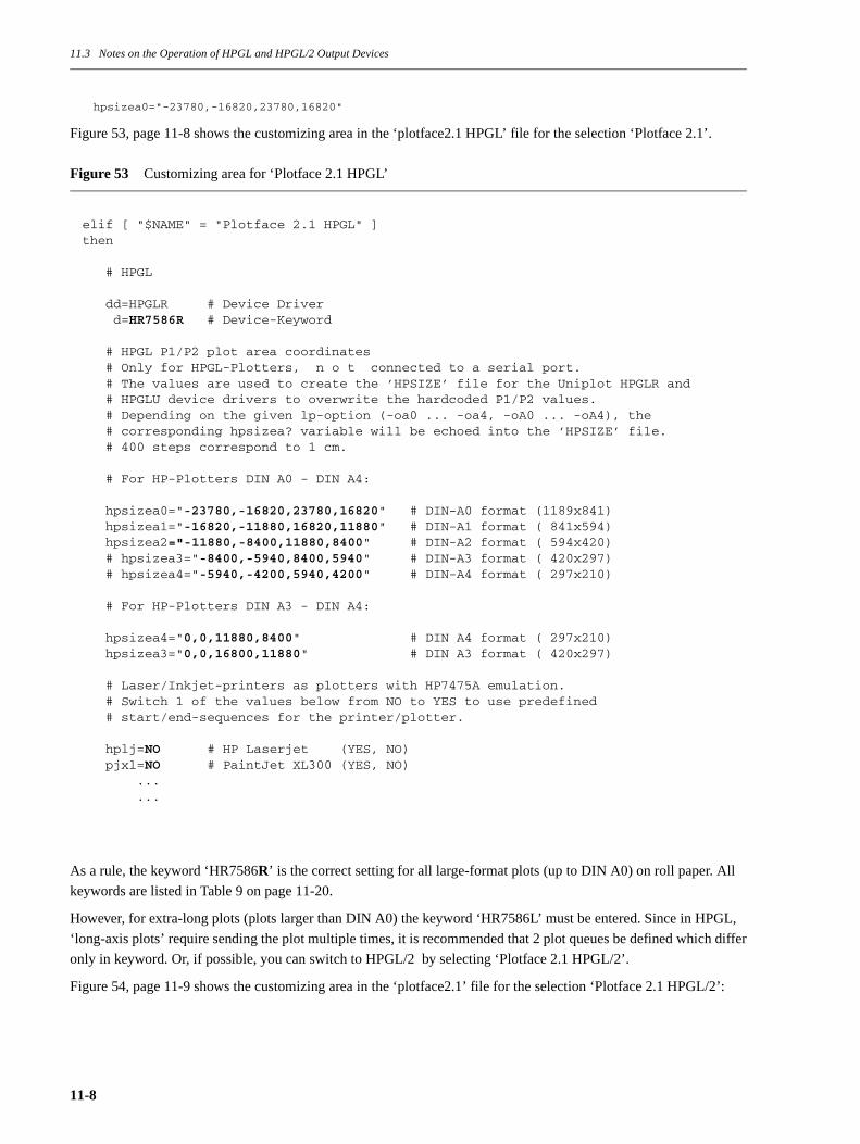
11.3 Notes on the Operation of HPGL and HPGL/2 Output Devices
hpsizea0="-23780,-16820,23780,16820"
Figure 53, page 11-8 shows the customizing area in the ‘plotface2.1 HPGL’ file for the selection ‘Plotface 2.1’.
Figure 53 Customizing area for ‘Plotface 2.1 HPGL’
As a rule, the keyword ‘HR7586R’ is the correct setting for all large-format plots (up to DIN A0) on roll paper. All
keywords are listed in Table 9 on page 11-20.
However, for extra-long plots (plots larger than DIN A0) the keyword ‘HR7586L’ must be entered. Since in HPGL,
‘long-axis plots’ require sending the plot multiple times, it is recommended that 2 plot queues be defined which differ
only in keyword. Or, if possible, you can switch to HPGL/2 by selecting ‘Plotface 2.1 HPGL/2’.
Figure 54, page 11-9 shows the customizing area in the ‘plotface2.1’ file for the selection ‘Plotface 2.1 HPGL/2’:
elif [ "$NAME" = "Plotface 2.1 HPGL" ]then
# HPGL
dd=HPGLR # Device Driver d=HR7586R # Device-Keyword
# HPGL P1/P2 plot area coordinates # Only for HPGL-Plotters, n o t connected to a serial port. # The values are used to create the ’HPSIZE’ file for the Uniplot HPGLR and # HPGLU device drivers to overwrite the hardcoded P1/P2 values. # Depending on the given lp-option (-oa0 ... -oa4, -oA0 ... -oA4), the # corresponding hpsizea? variable will be echoed into the ’HPSIZE’ file. # 400 steps correspond to 1 cm.
# For HP-Plotters DIN A0 - DIN A4:
hpsizea0="-23780,-16820,23780,16820" # DIN-A0 format (1189x841) hpsizea1="-16820,-11880,16820,11880" # DIN-A1 format ( 841x594) hpsizea2="-11880,-8400,11880,8400" # DIN-A2 format ( 594x420) # hpsizea3="-8400,-5940,8400,5940" # DIN-A3 format ( 420x297) # hpsizea4="-5940,-4200,5940,4200" # DIN-A4 format ( 297x210)
# For HP-Plotters DIN A3 - DIN A4:
hpsizea4="0,0,11880,8400" # DIN A4 format ( 297x210) hpsizea3="0,0,16800,11880" # DIN A3 format ( 420x297)
# Laser/Inkjet-printers as plotters with HP7475A emulation. # Switch 1 of the values below from NO to YES to use predefined # start/end-sequences for the printer/plotter.
hplj=NO # HP Laserjet (YES, NO) pjxl=NO # PaintJet XL300 (YES, NO) ... ...
11-8
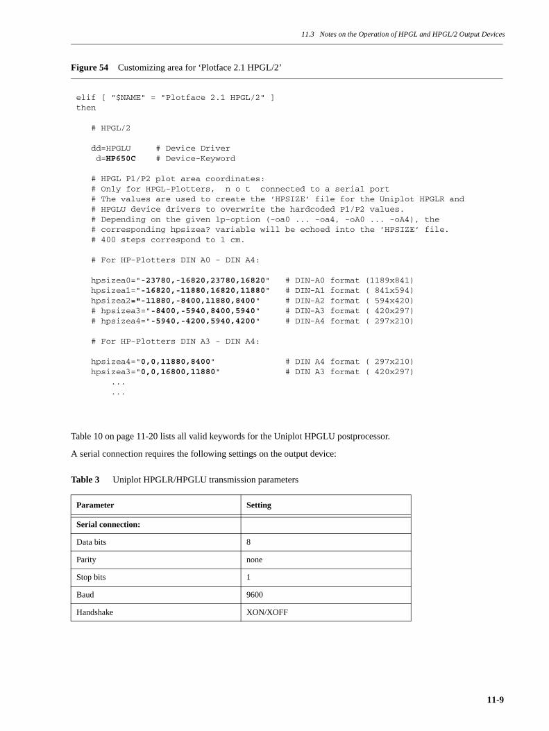
11.3 Notes on the Operation of HPGL and HPGL/2 Output Devices
Figure 54 Customizing area for ‘Plotface 2.1 HPGL/2’
Table 10 on page 11-20 lists all valid keywords for the Uniplot HPGLU postprocessor.
A serial connection requires the following settings on the output device:
Table 3 Uniplot HPGLR/HPGLU transmission parameters
Parameter Setting
Serial connection:
Data bits 8
Parity none
Stop bits 1
Baud 9600
Handshake XON/XOFF
elif [ "$NAME" = "Plotface 2.1 HPGL/2" ]then
# HPGL/2
dd=HPGLU # Device Driver d=HP650C # Device-Keyword
# HPGL P1/P2 plot area coordinates: # Only for HPGL-Plotters, n o t connected to a serial port # The values are used to create the ’HPSIZE’ file for the Uniplot HPGLR and # HPGLU device drivers to overwrite the hardcoded P1/P2 values. # Depending on the given lp-option (-oa0 ... -oa4, -oA0 ... -oA4), the # corresponding hpsizea? variable will be echoed into the ’HPSIZE’ file. # 400 steps correspond to 1 cm.
# For HP-Plotters DIN A0 - DIN A4:
hpsizea0="-23780,-16820,23780,16820" # DIN-A0 format (1189x841) hpsizea1="-16820,-11880,16820,11880" # DIN-A1 format ( 841x594) hpsizea2="-11880,-8400,11880,8400" # DIN-A2 format ( 594x420) # hpsizea3="-8400,-5940,8400,5940" # DIN-A3 format ( 420x297) # hpsizea4="-5940,-4200,5940,4200" # DIN-A4 format ( 297x210)
# For HP-Plotters DIN A3 - DIN A4:
hpsizea4="0,0,11880,8400" # DIN A4 format ( 297x210) hpsizea3="0,0,16800,11880" # DIN A3 format ( 420x297) ... ...
11-9
11.3 Notes on the Operation of HPGL and HPGL/2 Output Devices
11.3.1 DIN A4/A3 Printers (Laser, Ink Jet)
Almost all DIN A3/A4 output devices have HP7475 compatible emulation, and therefore can be operated with the
selection ‘Plotface 2.1 HPGL’. Simply change the keyword setting to ‘HR7475’.
Laser printers require a change-over sequence for HPGL operation which changes the laser printer over from PCL
mode to HPGL mode, and at the end back to PCL mode. In this case set the prepared variable ‘hplj’ to ‘YES’ (see fig-
ure 53, page 11-8). Then ‘plotface’ will automatically create the necessary start and end sequences.
Note: The original HP pen plotter HP7475A had a resolution of 402 steps/cm, instead of the usual 400 steps/cm. Laser
printers and other HP7475-emulating output devices are based on the correct 400 steps/cm. Therefore, using the Uni-
plot keyword ‘HR7475’ will output the plots a little too big!
Possible remedies are:
• Changing the resolution in the ‘DHCFILE’ file of the Uniplot HPGLR postprocessor. Change the ‘INCRE-
MENTS’ entry for the keyword ‘HR7475’ from ‘402’ to ‘400’, as described in section 9.7.1 “Making Changes in
the File DHCFILE” on page 9-13.
• Changing the standard directive ‘SCALE=1\$’ to ‘SCALE=0.995\$’.
• Using the selection ‘Plotface 2.1 HPGL/2’ and the keyword ‘LASERJET4’ or ‘LASERJET4R’.
11.3.2 HP75XX Series Pen Plotters
When using a pen plotter without internal optimization, it is recommended that ICEM DDN plot file optimization be
enabled. This is done at the following place in the customizing area of ‘plotface2.1’:
Change all values from ‘OFF’ to ‘ON’. The meaning of the optimizer parameters is given in Table 5 on page 11-16.
A different keyword must be used for single-sheet operation than for roll paper operation. Otherwise there is the dan-
ger that a single sheet plot which has not yet been taken out of the plotter could be overwritten by a subsequent plot-
ting job. The keywords for roll paper operation end with the letter ‘R’. The responsible entry in the ‘DHCFILE’ or
‘DHCEXT’ file is the ‘DEF. MODE’. For single-sheet operation this is ‘SELECTIVE’, and for roll paper operation it
is ‘LINEAR’.
During a serial connection ‘plotface’ attempts to find out the size and orientation of the inserted paper from the output
device using HPGL output requests. The corresponding feedback from the plotter is used to create the ‘HPSIZE’ file.
The ‘plot log’ file of the affiliated plot queue contains detailed information about the plotting area reported back to
‘plotface’ (also converted into mm).
11.3.3 DesignJet Series Raster Plotters
HP’s successful DesignJet series has almost completely replaced the use of pen plotters. The DesignJet 6xx/7xx series
can be operated either with the selection ‘Plotface 2.1 HPGL’ or with ‘Plotface 2.1 HPGL/2’. The default keywords in
‘plotface’ can be left as they are. The possible keywords for the DesignJet are given in Table 10 on page 11-20.
The plotter should have the following settings:
ICEM DDN optimizer parameters <<<<<<<<<<<<<<<<<<<<<<<<<<<<<<<<<<<<<<<<<<<<<< optprms="coin=OFF dup=OFF zero=OFF grid=OFF pc=OFF stats=ON"
11-10

11.3 Notes on the Operation of HPGL and HPGL/2 Output Devices
Table 4 DesignJet settings
The capability of the plotter to queue received plots and nest them in order to minimize paper use requires expanding
the plotter’s memory to at least 8 MB.
Pen attributes such as color and stroke width can either be set through a pen palette default on the plotter, or through
the software. The appropriate operating mode must be set on the plotter (see Table 4 on page 11-11). If software con-
trol of the attributes is desired, the necessary entries must be made in the ‘plotface’ file, or, if ‘Plotface 2.1 HPGL/2’ is
selected, in the ‘DHCEXT’ file of the Uniplot HPGLU postprocessor. This is because of the fact that ICEM applica-
tions output a pen number as a single pen attribute. Thus, Uniplot cannot obtain the additionally needed pen attributes
from the plot files of ICEM applications.
The following figure shows the section of the ‘DHCEXT’ file with the default pen attributes for a DesignJet.
Parameter Setting
Language HPGL/2, HP7586
Paper size Plotting area
Pen palette Palette or software
11-11

11.3 Notes on the Operation of HPGL and HPGL/2 Output Devices
Figure 55 Definition of pen attributes in the ‘DHCEXT’ file
It can be seen that all pens have been pre-assigned a stroke width of 0.35 mm. The color definitions expect data in
RGB notation1. The value ‘0’ designates none of the respective color, and the value ‘255’ sets it to its maximum. The
HP DesignJet offers the capability of making a test printout of 256 color settings. The color data is printed under the
color rectangles in RGB notation.
1. Red Green Blue components for a color.
** THIS SECTION RESERVED FOR HPGL2 PLOTTERS*DEVKEYWORD=******;PARITY=NONE; DATABITS=8;FORMAT=HPGL2; PAPERADV=A;DDOPT,1=BASE=64; LONGAXIS=NO; PS=YES; PW=YES; HC=YES;** HPON=ESC . Y HPOFF=ESC . Z*DDOPT,2=HPON=27,46,89; HPOFF=27,46,90;*PENMAP=1,2,3,4,5,6,7,8,9,10,11,12,13,14,15,0;PENTHICK=0.35,0.35,0.35,0.35,0.35,0.35,0.35,0.35,0.35,0.35,0.35,0.35,0.35,\0.35,0.35,0.35;* HPON IN IP IW NP PW CR PC CS CA SP PABEGPLOT=901,913,801,802,805,806,807,808,910,911,803,804;* HPOFF ENDPLOT=902;*COLOREXT=0,255,0,255,0,255;PENCOLOR=1,0,0,0;PENCOLOR=2,255,0,0;PENCOLOR=3,0,255,0;PENCOLOR=4,255,255,0;PENCOLOR=5,0,0,255;PENCOLOR=6,255,0,255;PENCOLOR=7,0,255,255;PENCOLOR=8,0,0,0;PENCOLOR=9,255,0,0;PENCOLOR=10,0,255,0;PENCOLOR=11,255,255,0;PENCOLOR=12,0,0,255;PENCOLOR=13,255,0,255;PENCOLOR=14,0,255,255;PENCOLOR=15,0,0,0;PENCOLOR=16,255,0,0;*DEVKEYWORD=HP650C; INTKEYWORD=HR7586; DDNAME=HPGLU; PROMPT=NO;DEVMODE=LINEAR; PLOTUNITS=CM; INCREMENT=400;NUMPENS=16; SURFACE=110.95,78.7;HWCHAR=YES; LCCHAR=YES; HWDOT=YES; HWDASH=YES; HWARC=YES;HWRCTF=YES; HWRCTS=NO; HWPLYF=NO; HWPLYS=NO; HWSCTF=YES; HWSCTS=NO;PAPERADV=A; PLOTCOOR=-20840,-16180,20840,16180;*
11-12
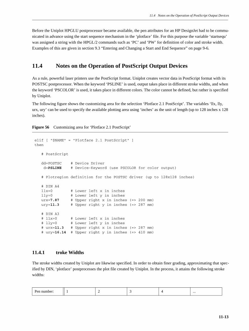
11.4 Notes on the Operation of PostScript Output Devices
Before the Uniplot HPGLU postprocessor became available, the pen attributes for an HP DesignJet had to be commu-
nicated in advance using the start sequence mechanism in the ‘plotface’ file. For this purpose the variable ‘startsequ’
was assigned a string with the HPGL/2 commands such as ‘PC’ and ‘PW’ for definition of color and stroke width.
Examples of this are given in section 9.3 “Entering and Changing a Start and End Sequence” on page 9-6.
11.4 Notes on the Operation of PostScript Output Devices
As a rule, powerful laser printers use the PostScript format. Uniplot creates vector data in PostScript format with its
POSTSC postprocessor. When the keyword ‘PSLINE’ is used, output takes place in different stroke widths, and when
the keyword ‘PSCOLOR’ is used, it takes place in different colors. The color cannot be defined, but rather is specified
by Uniplot.
The following figure shows the customizing area for the selection ‘Plotface 2.1 PostScript’. The variables ‘llx, lly,
urx, ury’ can be used to specify the available plotting area using ‘inches’ as the unit of length (up to 128 inches x 128
inches).
Figure 56 Customizing area for ‘Plotface 2.1 PostScript’
11.4.1 troke Widths
The stroke widths created by Uniplot are likewise specified. In order to obtain finer grading, approximating that spec-
ified by DIN, ‘plotface’ postprocesses the plot file created by Uniplot. In the process, it attains the following stroke
widths:
Pen number: 1 2 3 4 ...
elif [ "$NAME" = "Plotface 2.1 PostScript" ]then
# PostScript
dd=POSTSC # Device Driver d=PSLINE # Device-Keyword (use PSCOLOR for color output)
# Plotregion definition for the POSTSC driver (up to 128x128 inches)
# DIN A4 llx=0 # Lower left x in inches lly=0 # Lower left y in inches urx=7.87 # Upper right x in inches (=> 200 mm) ury=11.3 # Upper right y in inches (=> 287 mm)
# DIN A3 # llx=0 # Lower left x in inches # lly=0 # Lower left y in inches # urx=11.3 # Upper right x in inches (=> 287 mm) # ury=16.14 # Upper right y in inches (=> 410 mm)
11-13
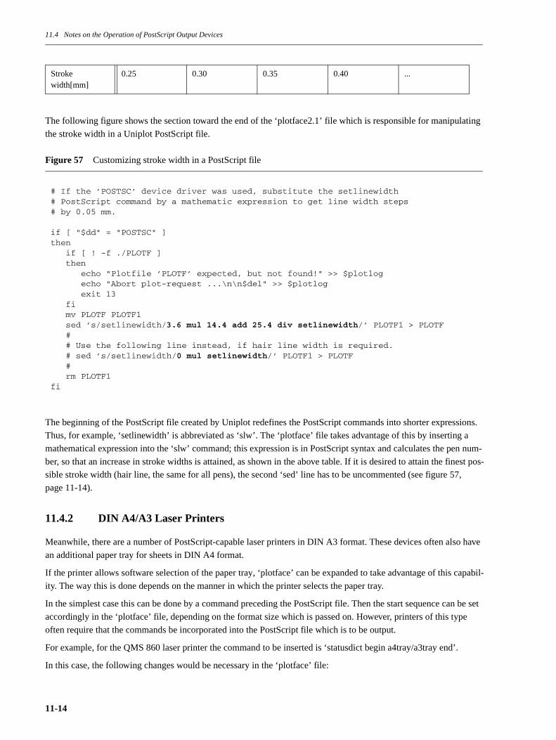
11.4 Notes on the Operation of PostScript Output Devices
The following figure shows the section toward the end of the ‘plotface2.1’ file which is responsible for manipulating
the stroke width in a Uniplot PostScript file.
Figure 57 Customizing stroke width in a PostScript file
The beginning of the PostScript file created by Uniplot redefines the PostScript commands into shorter expressions.
Thus, for example, ‘setlinewidth’ is abbreviated as ‘slw’. The ‘plotface’ file takes advantage of this by inserting a
mathematical expression into the ‘slw’ command; this expression is in PostScript syntax and calculates the pen num-
ber, so that an increase in stroke widths is attained, as shown in the above table. If it is desired to attain the finest pos-
sible stroke width (hair line, the same for all pens), the second ‘sed’ line has to be uncommented (see figure 57,
page 11-14).
11.4.2 DIN A4/A3 Laser Printers
Meanwhile, there are a number of PostScript-capable laser printers in DIN A3 format. These devices often also have
an additional paper tray for sheets in DIN A4 format.
If the printer allows software selection of the paper tray, ‘plotface’ can be expanded to take advantage of this capabil-
ity. The way this is done depends on the manner in which the printer selects the paper tray.
In the simplest case this can be done by a command preceding the PostScript file. Then the start sequence can be set
accordingly in the ‘plotface’ file, depending on the format size which is passed on. However, printers of this type
often require that the commands be incorporated into the PostScript file which is to be output.
For example, for the QMS 860 laser printer the command to be inserted is ‘statusdict begin a4tray/a3tray end’.
In this case, the following changes would be necessary in the ‘plotface’ file:
Stroke width[mm]
0.25 0.30 0.35 0.40 ...
# If the ’POSTSC’ device driver was used, substitute the setlinewidth # PostScript command by a mathematic expression to get line width steps # by 0.05 mm.
if [ "$dd" = "POSTSC" ]then if [ ! -f ./PLOTF ] then echo "Plotfile ’PLOTF’ expected, but not found!" >> $plotlog echo "Abort plot-request ...\n\n$del" >> $plotlog exit 13 fi mv PLOTF PLOTF1 sed ’s/setlinewidth/3.6 mul 14.4 add 25.4 div setlinewidth/’ PLOTF1 > PLOTF # # Use the following line instead, if hair line width is required. # sed ’s/setlinewidth/0 mul setlinewidth/’ PLOTF1 > PLOTF # rm PLOTF1fi
11-14
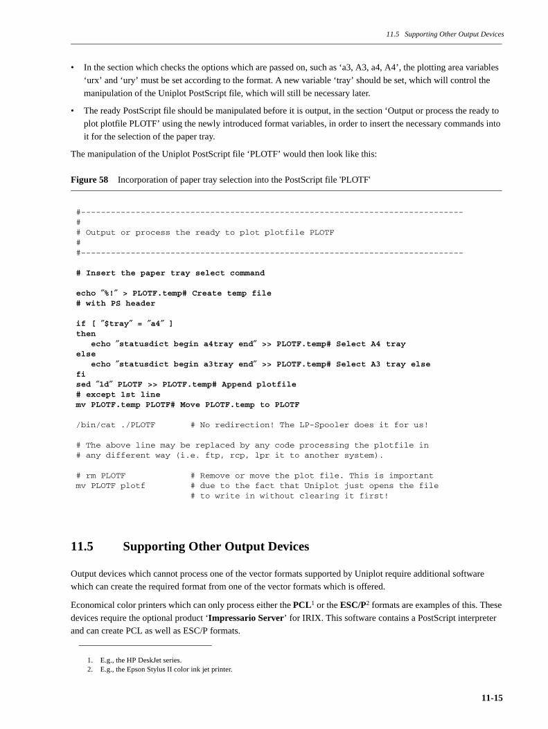
11.5 Supporting Other Output Devices
• In the section which checks the options which are passed on, such as ‘a3, A3, a4, A4’, the plotting area variables
‘urx’ and ‘ury’ must be set according to the format. A new variable ‘tray’ should be set, which will control the
manipulation of the Uniplot PostScript file, which will still be necessary later.
• The ready PostScript file should be manipulated before it is output, in the section ‘Output or process the ready to
plot plotfile PLOTF’ using the newly introduced format variables, in order to insert the necessary commands into
it for the selection of the paper tray.
The manipulation of the Uniplot PostScript file ‘PLOTF’ would then look like this:
Figure 58 Incorporation of paper tray selection into the PostScript file 'PLOTF'
11.5 Supporting Other Output Devices
Output devices which cannot process one of the vector formats supported by Uniplot require additional software
which can create the required format from one of the vector formats which is offered.
Economical color printers which can only process either the PCL1 or the ESC/P2 formats are examples of this. These
devices require the optional product ‘Impressario Server’ for IRIX. This software contains a PostScript interpreter
and can create PCL as well as ESC/P formats.
1. E.g., the HP DeskJet series.2. E.g., the Epson Stylus II color ink jet printer.
#-----------------------------------------------------------------------------## Output or process the ready to plot plotfile PLOTF##-----------------------------------------------------------------------------
# Insert the paper tray select command
echo ″%!″ > PLOTF.temp# Create temp file# with PS header
if [ ″$tray″ = ″a4″ ]then echo ″statusdict begin a4tray end″ >> PLOTF.temp# Select A4 trayelse echo ″statusdict begin a3tray end″ >> PLOTF.temp# Select A3 tray elsefised ″1d″ PLOTF >> PLOTF.temp# Append plotfile# except 1st linemv PLOTF.temp PLOTF# Move PLOTF.temp to PLOTF
/bin/cat ./PLOTF # No redirection! The LP-Spooler does it for us!
# The above line may be replaced by any code processing the plotfile in # any different way (i.e. ftp, rcp, lpr it to another system).
# rm PLOTF # Remove or move the plot file. This is importantmv PLOTF plotf # due to the fact that Uniplot just opens the file # to write in without clearing it first!
11-15

11.6 Manual Use of the Uniplot Preprocessors and Postprocessors
The PlotServer Package is customized by using the LP queue template ‘Plotface 2.1 PostScript’, but, instead of using
the ‘cat’ command to output the PostScript file which is created, it is passed on to the Impressario software, which
has final control of the output device.
By supporting the PostScript format the ‘Impressario Server’ software offers ideal integration with the IRIX system.
This is because this format allows optimal use to be made of all IRIX application programs, which create only Post-
Script files. This makes it possible to output screendumps1, vector plots, and the output of the IRIX programs Insight2,
Showcase3, etc., on non-PostScript-compatible devices.
11.6 Manual Use of the Uniplot Preprocessors and Postprocessors
Manual use of the Uniplot postprocessors requires an input file in the neutral Uniplot format ‘NPFILE’. Preprocessors
can be used to create this format from the ICEM application plot formats as follows:
ICEM Surf creates this format directly, so that in this case no preconversion is necessary. When using the programs
‘optim’ and ‘ductuni’ make sure that there is not already a file having the name ‘NPFILE’ in the current directory,
otherwise the plot file will be appended to it. The programs ‘optim’ and ‘ductuni’ are also found in the ICEM Plot-
Server installation directory under the subdirectory ‘app2uni’.
The program ‘optim’ also offers a series of other parameters which can be passed and which can be used to control the
plot file optimization (e.g., the sorting of vectors by pen, deletion of overlapping vectors, etc.). However, as a rule,
optimization is not necessary if the final output of the plot file is to be done on a raster device. And this ‘optim’ pro-
cess can require a great deal of computing time and working memory. For the sake of completeness, here is a table
giving the possible ‘optim’ parameters4.
Table 5 Optimization parameters of the ‘optim‘ program
1. Created with the IRIX program ‘snapshot’ or ‘scrsave’.2. IRIX Online manuals.3. A simple IRIX DTP multimedia program.
ICEM DDN - tape9: /icem/bin/optim i=tape9_file o=NPFILE fmt=NPFILE
Duct - plot.npf /duct/plotter/ductuni -iplot.npf
4. In the ‘plotface’ file the ‘optim’ parameters are controlled by the ‘optprms’ variable.
Parameter Description
zero=[ON,OFF] Remove vectors with length
dup=[ON,OFF] Remove duplicate vectors
coin=[ON,OFF] Combine overlapping vectors
pc=[ON,OFF] Sort by pen
grid=[ON,OFF] Optimize in an imposed raster
stats=[ON,OFF] Display optimization statistics
11-16
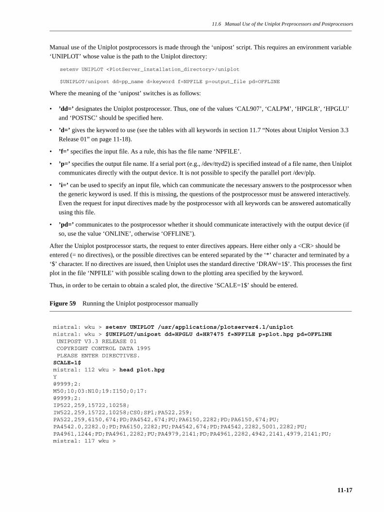
11.6 Manual Use of the Uniplot Preprocessors and Postprocessors
Manual use of the Uniplot postprocessors is made through the ‘unipost’ script. This requires an environment variable
‘UNIPLOT’ whose value is the path to the Uniplot directory:
setenv UNIPLOT <PlotServer_installation_directory>/uniplot
$UNIPLOT/unipost dd=pp_name d=keyword f=NPFILE p=output_file pd=OFFLINE
Where the meaning of the ‘unipost’ switches is as follows:
• ’dd=’ designates the Uniplot postprocessor. Thus, one of the values ‘CAL907’, ‘CALPM’, ‘HPGLR’, ‘HPGLU’
and ‘POSTSC’ should be specified here.
• ’d=’ gives the keyword to use (see the tables with all keywords in section 11.7 “Notes about Uniplot Version 3.3
Release 01” on page 11-18).
• ’f=’ specifies the input file. As a rule, this has the file name ‘NPFILE’.
• ’p=’ specifies the output file name. If a serial port (e.g., /dev/ttyd2) is specified instead of a file name, then Uniplot
communicates directly with the output device. It is not possible to specify the parallel port /dev/plp.
• ’i=’ can be used to specify an input file, which can communicate the necessary answers to the postprocessor when
the generic keyword is used. If this is missing, the questions of the postprocessor must be answered interactively.
Even the request for input directives made by the postprocessor with all keywords can be answered automatically
using this file.
• ’pd=’ communicates to the postprocessor whether it should communicate interactively with the output device (if
so, use the value ‘ONLINE’, otherwise ‘OFFLINE’).
After the Uniplot postprocessor starts, the request to enter directives appears. Here either only a <CR> should be
entered (= no directives), or the possible directives can be entered separated by the ‘*’ character and terminated by a
‘$’ character. If no directives are issued, then Uniplot uses the standard directive ‘DRAW=1$’. This processes the first
plot in the file ‘NPFILE’ with possible scaling down to the plotting area specified by the keyword.
Thus, in order to be certain to obtain a scaled plot, the directive ‘SCALE=1$’ should be entered.
Figure 59 Running the Uniplot postprocessor manually
mistral: wku > setenv UNIPLOT /usr/applications/plotserver4.1/uniplotmistral: wku > $UNIPLOT/unipost dd=HPGLU d=HR7475 f=NPFILE p=plot.hpg pd=OFFLINE UNIPOST V3.3 RELEASE 01 COPYRIGHT CONTROL DATA 1995 PLEASE ENTER DIRECTIVES.SCALE=1$mistral: 112 wku > head plot.hpgY@9999;2:M50;10;03:N10;19:I150;0;17:@9999;2:IP522,259,15722,10258;IW522,259,15722,10258;CS0;SP1;PA522,259;PA522,259,6150,674;PD;PA4542,674;PU;PA6150,2282;PD;PA6150,674;PU;PA4542.0,2282.0;PD;PA6150,2282;PU;PA4542,674;PD;PA4542,2282,5001,2282;PU;PA4961,1244;PD;PA4961,2282;PU;PA4979,2141;PD;PA4961,2282,4942,2141,4979,2141;PU;mistral: 117 wku >
11-17
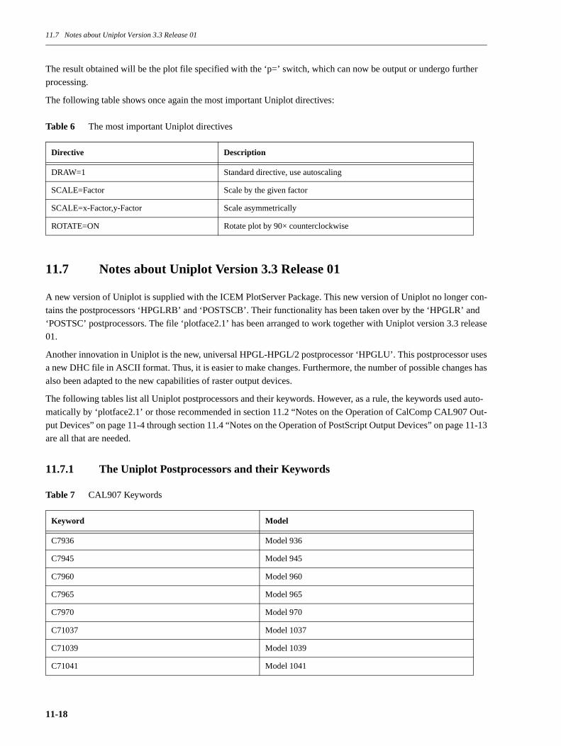
11.7 Notes about Uniplot Version 3.3 Release 01
The result obtained will be the plot file specified with the ‘p=’ switch, which can now be output or undergo further
processing.
The following table shows once again the most important Uniplot directives:
Table 6 The most important Uniplot directives
11.7 Notes about Uniplot Version 3.3 Release 01
A new version of Uniplot is supplied with the ICEM PlotServer Package. This new version of Uniplot no longer con-
tains the postprocessors ‘HPGLRB’ and ‘POSTSCB’. Their functionality has been taken over by the ‘HPGLR’ and
‘POSTSC’ postprocessors. The file ‘plotface2.1’ has been arranged to work together with Uniplot version 3.3 release
01.
Another innovation in Uniplot is the new, universal HPGL-HPGL/2 postprocessor ‘HPGLU’. This postprocessor uses
a new DHC file in ASCII format. Thus, it is easier to make changes. Furthermore, the number of possible changes has
also been adapted to the new capabilities of raster output devices.
The following tables list all Uniplot postprocessors and their keywords. However, as a rule, the keywords used auto-
matically by ‘plotface2.1’ or those recommended in section 11.2 “Notes on the Operation of CalComp CAL907 Out-
put Devices” on page 11-4 through section 11.4 “Notes on the Operation of PostScript Output Devices” on page 11-13
are all that are needed.
11.7.1 The Uniplot Postprocessors and their Keywords
Table 7 CAL907 Keywords
Directive Description
DRAW=1 Standard directive, use autoscaling
SCALE=Factor Scale by the given factor
SCALE=x-Factor,y-Factor Scale asymmetrically
ROTATE=ON Rotate plot by 90× counterclockwise
Keyword Model
C7936 Model 936
C7945 Model 945
C7960 Model 960
C7965 Model 965
C7970 Model 970
C71037 Model 1037
C71039 Model 1039
C71041 Model 1041
11-18

11.7 Notes about Uniplot Version 3.3 Release 01
Table 8 CALPM Keywords
C71042C Model 1042 with cut paper option
C71042R Model 1042 with roll paper option
C71043 Model 1043
C71044C Model 1044 with cut paper option
C71044R Model 1044 with roll paper option
C71051 Model 1051
C71055 Model 1055
C71060 Model 1060
C71065 Model 1065
C71073C Model 1073 with cut paper option
C71073R Model 1073 with roll paper option
C71075C Model 1075 with cut paper option
C71075R Model 1075 with roll paper option
C71077C Model 1077 with cut paper option
C71077R Model 1077 with roll paper option
CP5732 Model 5732 - 200 dots per cm
CP5734 Model 5734 - 400 dots per cm
CP5742 Model 5742 - 200 dots per cm
CP5744 Model 5744 - 400 dots per cm
CP5752 Model 5752 - 200 dots per cm
CP5754 Model 5754 - 400 dots per cm
CAL907 Generic keyword
Keyword Model
CX1023 Model 1023
X1041 Model 1041
X1042C Model 1042 with cut paper option
X1042R Model 1042 with roll paper option
X1043 Model 1043
X1044C Model 1044 with cut paper option
X1044R Model 1044 with roll paper option
CX5723 Model 5723 - 200 dots per cm
Keyword Model
11-19
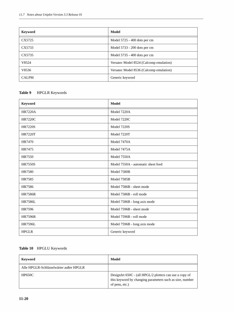
11.7 Notes about Uniplot Version 3.3 Release 01
Table 9 HPGLR Keywords
Table 10 HPGLU Keywords
CX5725 Model 5725 - 400 dots per cm
CX5733 Model 5733 - 200 dots per cm
CX5735 Model 5735 - 400 dots per cm
V8524 Versatec Model 8524 (Calcomp emulation)
V8536 Versatec Model 8536 (Calcomp emulation)
CALPM Generic keyword
Keyword Model
HR7220A Model 7220A
HR7220C Model 7220C
HR7220S Model 7220S
HR7220T Model 7220T
HR7470 Model 7470A
HR7475 Model 7475A
HR7550 Model 7550A
HR7550S Model 7550A - automatic sheet feed
HR7580 Model 7580B
HR7585 Model 7585B
HR7586 Model 7586B - sheet mode
HR7586R Model 7586B - roll mode
HR7586L Model 7586B - long axis mode
HR7596 Model 7596B - sheet mode
HR7596R Model 7596B - roll mode
HR7596L Model 7596B - long axis mode
HPGLR Generic keyword
Keyword Model
Alle HPGLR-Schlüsselwärter außer HPGLR
HP650C DesignJet 650C - (all HPGL/2 plotters can use a copy of this keyword by changing parameters such as size, number of pens, etc.)
Keyword Model
11-20
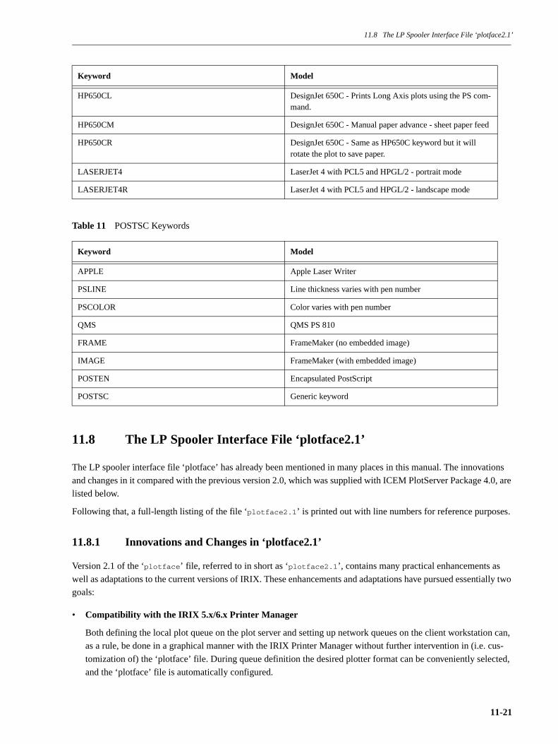
11.8 The LP Spooler Interface File ‘plotface2.1’
Table 11 POSTSC Keywords
11.8 The LP Spooler Interface File ‘plotface2.1’
The LP spooler interface file ‘plotface’ has already been mentioned in many places in this manual. The innovations
and changes in it compared with the previous version 2.0, which was supplied with ICEM PlotServer Package 4.0, are
listed below.
Following that, a full-length listing of the file ‘plotface2.1’ is printed out with line numbers for reference purposes.
11.8.1 Innovations and Changes in ‘plotface2.1’
Version 2.1 of the ‘plotface’ file, referred to in short as ‘plotface2.1’, contains many practical enhancements as
well as adaptations to the current versions of IRIX. These enhancements and adaptations have pursued essentially two
goals:
• Compatibility with the IRIX 5.x/6.x Printer Manager
Both defining the local plot queue on the plot server and setting up network queues on the client workstation can,
as a rule, be done in a graphical manner with the IRIX Printer Manager without further intervention in (i.e. cus-
tomization of) the ‘plotface’ file. During queue definition the desired plotter format can be conveniently selected,
and the ‘plotface’ file is automatically configured.
HP650CL DesignJet 650C - Prints Long Axis plots using the PS com-mand.
HP650CM DesignJet 650C - Manual paper advance - sheet paper feed
HP650CR DesignJet 650C - Same as HP650C keyword but it will rotate the plot to save paper.
LASERJET4 LaserJet 4 with PCL5 and HPGL/2 - portrait mode
LASERJET4R LaserJet 4 with PCL5 and HPGL/2 - landscape mode
Keyword Model
APPLE Apple Laser Writer
PSLINE Line thickness varies with pen number
PSCOLOR Color varies with pen number
QMS QMS PS 810
FRAME FrameMaker (no embedded image)
IMAGE FrameMaker (with embedded image)
POSTEN Encapsulated PostScript
POSTSC Generic keyword
Keyword Model
11-21
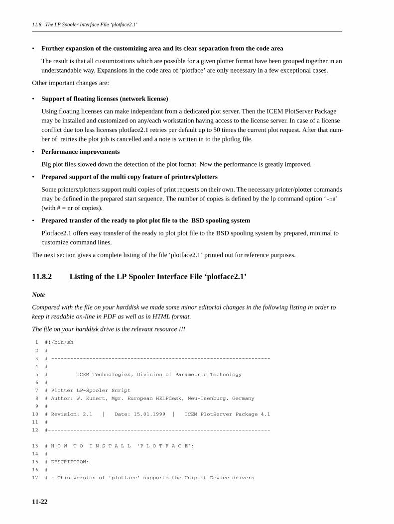
11.8 The LP Spooler Interface File ‘plotface2.1’
• Further expansion of the customizing area and its clear separation from the code area
The result is that all customizations which are possible for a given plotter format have been grouped together in an
understandable way. Expansions in the code area of ‘plotface’ are only necessary in a few exceptional cases.
Other important changes are:
• Support of floating licenses (network license)
Using floating licenses can make independant from a dedicated plot server. Then the ICEM PlotServer Package
may be installed and customized on any/each workstation having access to the license server. In case of a license
conflict due too less licenses plotface2.1 retries per default up to 50 times the current plot request. After that num-
ber of retries the plot job is cancelled and a note is written in to the plotlog file.
• Performance improvements
Big plot files slowed down the detection of the plot format. Now the performance is greatly improved.
• Prepared support of the multi copy feature of printers/plotters
Some printers/plotters support multi copies of print requests on their own. The necessary printer/plotter commands
may be defined in the prepared start sequence. The number of copies is defined by the lp command option ‘-n#’
(with # = nr of copies).
• Prepared transfer of the ready to plot plot file to the BSD spooling system
Plotface2.1 offers easy transfer of the ready to plot plot file to the BSD spooling system by prepared, minimal to
customize command lines.
The next section gives a complete listing of the file ‘plotface2.1’ printed out for reference purposes.
11.8.2 Listing of the LP Spooler Interface File ‘plotface2.1’
Note
Compared with the file on your harddisk we made some minor editorial changes in the following listing in order to
keep it readable on-line in PDF as well as in HTML format.
The file on your harddisk drive is the relevant resource !!!
1 #!/bin/sh
2 #
3 # ---------------------------------------------------------------------
4 #
5 # ICEM Technologies, Division of Parametric Technology
6 #
7 # Plotter LP-Spooler Script
8 # Author: W. Kunert, Mgr. European HELPdesk, Neu-Isenburg, Germany
9 #
10 # Revision: 2.1 | Date: 15.01.1999 | ICEM PlotServer Package 4.1
11 #
12 #----------------------------------------------------------------------
13 # H O W T O I N S T A L L ’P L O T F A C E’:
14 #
15 # DESCRIPTION:
16 #
17 # - This version of ’plotface’ supports the Uniplot Device drivers
11-22
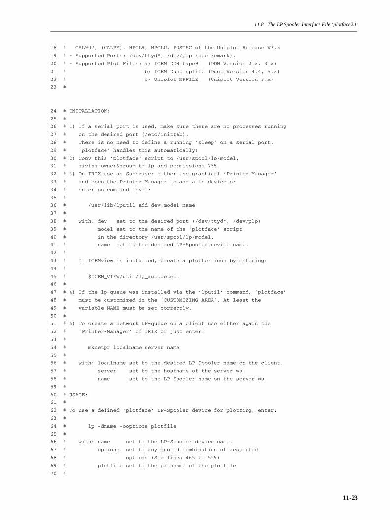
11.8 The LP Spooler Interface File ‘plotface2.1’
18 # CAL907, (CALPM), HPGLR, HPGLU, POSTSC of the Uniplot Release V3.x
19 # - Supported Ports: /dev/ttyd*, /dev/plp (see remark).
20 # - Supported Plot Files: a) ICEM DDN tape9 (DDN Version 2.x, 3.x)
21 # b) ICEM Duct npfile (Duct Version 4.4, 5.x)
22 # c) Uniplot NPFILE (Uniplot Version 3.x)
23 #
24 # INSTALLATION:
25 #
26 # 1) If a serial port is used, make sure there are no processes running
27 # on the desired port (/etc/inittab).
28 # There is no need to define a running ’sleep’ on a serial port.
29 # ’plotface’ handles this automatically!
30 # 2) Copy this ’plotface’ script to /usr/spool/lp/model,
31 # giving owner&group to lp and permissions 755.
32 # 3) On IRIX use as Superuser either the graphical ’Printer Manager’
33 # and open the Printer Manager to add a lp-device or
34 # enter on command level:
35 #
36 # /usr/lib/lputil add dev model name
37 #
38 # with: dev set to the desired port (/dev/ttyd*, /dev/plp)
39 # model set to the name of the ’plotface’ script
40 # in the directory /usr/spool/lp/model.
41 # name set to the desired LP-Spooler device name.
42 #
43 # If ICEMview is installed, create a plotter icon by entering:
44 #
45 # $ICEM_VIEW/util/lp_autodetect
46 #
47 # 4) If the lp-queue was installed via the ’lputil’ command, ’plotface’
48 # must be customized in the ’CUSTOMIZING AREA’. At least the
49 # variable NAME must be set correctly.
50 #
51 # 5) To create a network LP-queue on a client use either again the
52 # ’Printer-Manager’ of IRIX or just enter:
53 #
54 # mknetpr localname server name
55 #
56 # with: localname set to the desired LP-Spooler name on the client.
57 # server set to the hostname of the server ws.
58 # name set to the LP-Spooler name on the server ws.
59 #
60 # USAGE:
61 #
62 # To use a defined ’plotface’ LP-Spooler device for plotting, enter:
63 #
64 # lp -dname -ooptions plotfile
65 #
66 # with: name set to the LP-Spooler device name.
67 # options set to any quoted combination of respected
68 # options (See lines 465 to 559)
69 # plotfile set to the pathname of the plotfile
70 #
11-23

11.8 The LP Spooler Interface File ‘plotface2.1’
71 # The plotfile needs permissions 644,
72 # the directory of the plotfile needs permissions 755.
73 #
74 # IMPORTANT REMARK:
75 #
76 # This version of ’plotface’ plots on disk first (file PLOTF) and
77 # cats it on the port. Even if no plotting on a port is desired
78 # the port /dev/plp should be used when creating the lp-queue. The port
79 # /dev/null is no longer supported as in prior versions of ’plotface’!
80 # This circumvents problems with the IRIX Printer Manager and the
81 # ’mknetpr’-command.
82 # Code to process the plotfile may be added after the line headed
83 # ’# Output or process the ready to plot plotfile PLOTF’
84 #
85 #----------------------------------------------------------------------
86 #
87 # Variables for script-internal usage - don’t change!
88 #
89 #----------------------------------------------------------------------
90 plotter="‘basename $0‘" # lp-spooler device name
91 seqid="$1" # request id
92 name="$2" # user name
93 title="$3" # title string (lp -t) - won’t be used by default!
94 copies=$4 # number of copies (lp -n) - won’t be used by default!
95 options="$5" # options string (lp -o)
96 pfile="$6" # only 1 plotfile will be plotted!
97 plotlog="plotlog"
98 del="================================================================="
99 port="‘cat /usr/spool/lp/member/$plotter | grep /dev/‘"
100 p="$port"
101 ssequsent="false"
102 inpdirs=""
103 #---------------------------------------------------------------------
104 #---------------------------------------------------------------------
105 #- START OF CUSTOMIZING AREA -----------------------------------------
106 #---------------------------------------------------------------------
107 #---------------------------------------------------------------------
108 # Information for the IRIX 5.x/6.x Printer Manager, don’t change!
109 # NAME=Plotface 2.1 Cal907
110 # NAME=Plotface 2.1 HPGL
111 # NAME=Plotface 2.1 HPGL/2
112 # NAME=Plotface 2.1 PostScript
113 # Set the NAME variable below to 1 of the 4 values shown above,
114 # filling the double quotes with 1 of the 4 strings shown above.
115 # The NAME variable below will be set autom. by the Printer Manager,
116 # if the IRIX Printer Manager is used to install the plot queue!
11-24
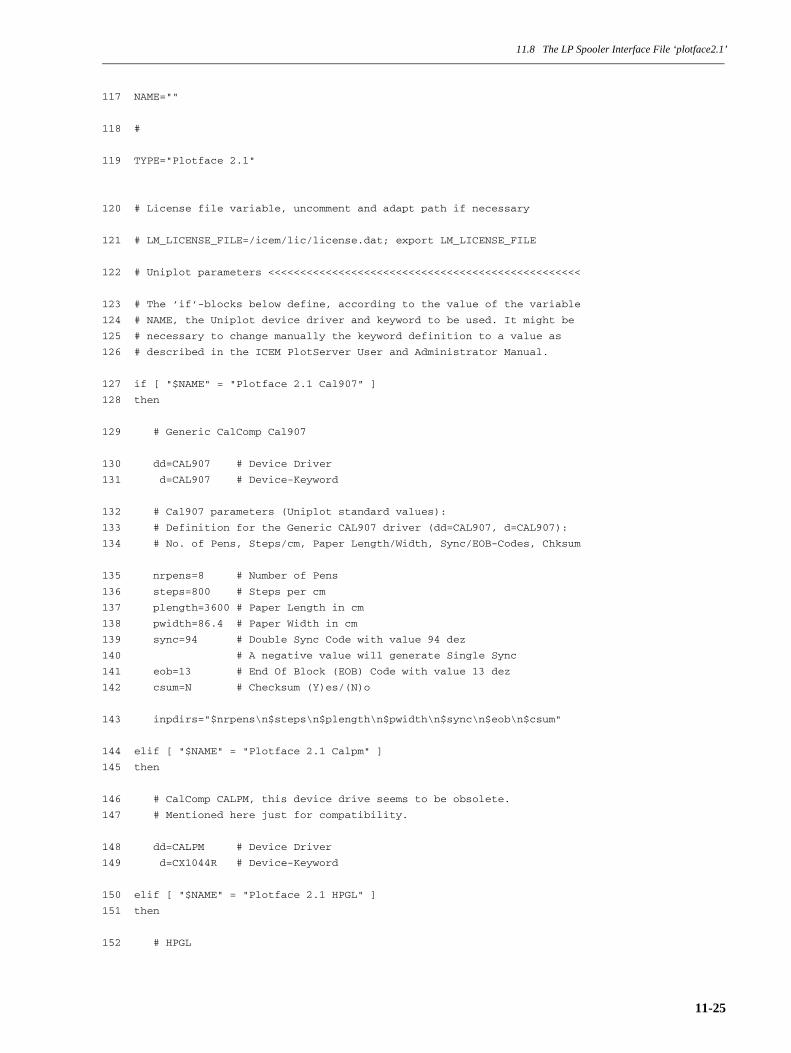
11.8 The LP Spooler Interface File ‘plotface2.1’
117 NAME=""
118 #
119 TYPE="Plotface 2.1"
120 # License file variable, uncomment and adapt path if necessary
121 # LM_LICENSE_FILE=/icem/lic/license.dat; export LM_LICENSE_FILE
122 # Uniplot parameters <<<<<<<<<<<<<<<<<<<<<<<<<<<<<<<<<<<<<<<<<<<<<<<<<
123 # The ’if’-blocks below define, according to the value of the variable
124 # NAME, the Uniplot device driver and keyword to be used. It might be
125 # necessary to change manually the keyword definition to a value as
126 # described in the ICEM PlotServer User and Administrator Manual.
127 if [ "$NAME" = "Plotface 2.1 Cal907" ]
128 then
129 # Generic CalComp Cal907
130 dd=CAL907 # Device Driver
131 d=CAL907 # Device-Keyword
132 # Cal907 parameters (Uniplot standard values):
133 # Definition for the Generic CAL907 driver (dd=CAL907, d=CAL907):
134 # No. of Pens, Steps/cm, Paper Length/Width, Sync/EOB-Codes, Chksum
135 nrpens=8 # Number of Pens
136 steps=800 # Steps per cm
137 plength=3600 # Paper Length in cm
138 pwidth=86.4 # Paper Width in cm
139 sync=94 # Double Sync Code with value 94 dez
140 # A negative value will generate Single Sync
141 eob=13 # End Of Block (EOB) Code with value 13 dez
142 csum=N # Checksum (Y)es/(N)o
143 inpdirs="$nrpens\n$steps\n$plength\n$pwidth\n$sync\n$eob\n$csum"
144 elif [ "$NAME" = "Plotface 2.1 Calpm" ]
145 then
146 # CalComp CALPM, this device drive seems to be obsolete.
147 # Mentioned here just for compatibility.
148 dd=CALPM # Device Driver
149 d=CX1044R # Device-Keyword
150 elif [ "$NAME" = "Plotface 2.1 HPGL" ]
151 then
152 # HPGL
11-25
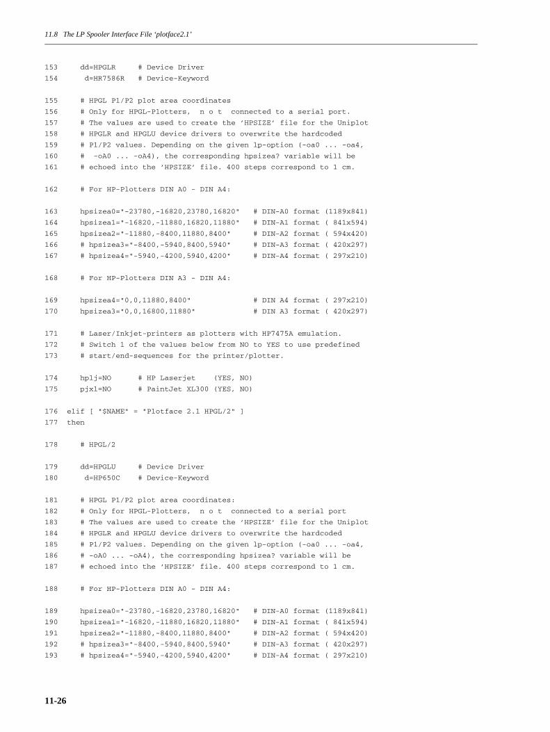
11.8 The LP Spooler Interface File ‘plotface2.1’
153 dd=HPGLR # Device Driver
154 d=HR7586R # Device-Keyword
155 # HPGL P1/P2 plot area coordinates
156 # Only for HPGL-Plotters, n o t connected to a serial port.
157 # The values are used to create the ’HPSIZE’ file for the Uniplot
158 # HPGLR and HPGLU device drivers to overwrite the hardcoded
159 # P1/P2 values. Depending on the given lp-option (-oa0 ... -oa4,
160 # -oA0 ... -oA4), the corresponding hpsizea? variable will be
161 # echoed into the ’HPSIZE’ file. 400 steps correspond to 1 cm.
162 # For HP-Plotters DIN A0 - DIN A4:
163 hpsizea0="-23780,-16820,23780,16820" # DIN-A0 format (1189x841)
164 hpsizea1="-16820,-11880,16820,11880" # DIN-A1 format ( 841x594)
165 hpsizea2="-11880,-8400,11880,8400" # DIN-A2 format ( 594x420)
166 # hpsizea3="-8400,-5940,8400,5940" # DIN-A3 format ( 420x297)
167 # hpsizea4="-5940,-4200,5940,4200" # DIN-A4 format ( 297x210)
168 # For HP-Plotters DIN A3 - DIN A4:
169 hpsizea4="0,0,11880,8400" # DIN A4 format ( 297x210)
170 hpsizea3="0,0,16800,11880" # DIN A3 format ( 420x297)
171 # Laser/Inkjet-printers as plotters with HP7475A emulation.
172 # Switch 1 of the values below from NO to YES to use predefined
173 # start/end-sequences for the printer/plotter.
174 hplj=NO # HP Laserjet (YES, NO)
175 pjxl=NO # PaintJet XL300 (YES, NO)
176 elif [ "$NAME" = "Plotface 2.1 HPGL/2" ]
177 then
178 # HPGL/2
179 dd=HPGLU # Device Driver
180 d=HP650C # Device-Keyword
181 # HPGL P1/P2 plot area coordinates:
182 # Only for HPGL-Plotters, n o t connected to a serial port
183 # The values are used to create the ’HPSIZE’ file for the Uniplot
184 # HPGLR and HPGLU device drivers to overwrite the hardcoded
185 # P1/P2 values. Depending on the given lp-option (-oa0 ... -oa4,
186 # -oA0 ... -oA4), the corresponding hpsizea? variable will be
187 # echoed into the ’HPSIZE’ file. 400 steps correspond to 1 cm.
188 # For HP-Plotters DIN A0 - DIN A4:
189 hpsizea0="-23780,-16820,23780,16820" # DIN-A0 format (1189x841)
190 hpsizea1="-16820,-11880,16820,11880" # DIN-A1 format ( 841x594)
191 hpsizea2="-11880,-8400,11880,8400" # DIN-A2 format ( 594x420)
192 # hpsizea3="-8400,-5940,8400,5940" # DIN-A3 format ( 420x297)
193 # hpsizea4="-5940,-4200,5940,4200" # DIN-A4 format ( 297x210)
11-26

11.8 The LP Spooler Interface File ‘plotface2.1’
194 # For HP-Plotters DIN A3 - DIN A4:
195 hpsizea4="0,0,11880,8400" # DIN A4 format ( 297x210)
196 hpsizea3="0,0,16800,11880" # DIN A3 format ( 420x297)
197 elif [ "$NAME" = "Plotface 2.1 PostScript" ]
198 then
199 # PostScript
200 dd=POSTSC # Device Driver
201 d=PSLINE # Device-Keyword (use PSCOLOR for color output)
202 # Plotregion definition for POSTSC driver (up to 128x128 inches)
203 # DIN A4
204 llx=0 # Lower left x in inches
205 lly=0 # Lower left y in inches
206 urx=7.87 # Upper right x in inches (=> 200 mm)
207 ury=11.3 # Upper right y in inches (=> 287 mm)
208 # DIN A3
209 # llx=0 # Lower left x in inches
210 # lly=0 # Lower left y in inches
211 # urx=11.3 # Upper right x in inches (=> 287 mm)
212 # ury=16.14 # Upper right y in inches (=> 410 mm)
213 inpdirs="$llx\n$lly\n$urx\n$ury"
214 else
215 echo "No NAME variable defined!" >> $plotlog
216 echo "Check the Customizing Area of plotface." >> $plotlog
217 echo "Abort plot-request ...\n\n$del" >> $plotlog
218 exit 5
219 fi
220 # Path to Uniplot <<<<<<<<<<<<<<<<<<<<<<<<<<<<<<<<<<<<<<<<<<<<<<<<<<<<
221 plotserver=/usr/applications/plotserver4.1
222 # Default directives <<<<<<<<<<<<<<<<<<<<<<<<<<<<<<<<<<<<<<<<<<<<<<<<<
223 directive1="SCALE=1\$"
224 directive2="NONE*" # any Uniplot directive has to end with an ’*’
225 # (ROTATE=ON, ORIGIN=x.x,y.y, etc)
226 # Path to the ICEM DDN converter program (tape9 -> NPFILE) <<<<<<<<<<<
227 ddn2npf=$plotserver/app2uni/optim
228 # Path to the ICEM DUCT converter program (duct.npf -> NPFILE) <<<<<<<
229 duct2npf=$plotserver/app2uni/ductuni
11-27

11.8 The LP Spooler Interface File ‘plotface2.1’
230 # Path to the HPGL to NPFILE converter program (HPGL -> NPFILE) <<<<<<
231 hp2npf=$plotserver/app2uni/hp2npf
232 # ICEM DDN optimizer parameters <<<<<<<<<<<<<<<<<<<<<<<<<<<<<<<<<<<<<<
233 optprms="coin=OFF dup=OFF zero=OFF grid=OFF pc=OFF stats=ON"
234 # Enable/Disable auto sleep setup/verify function
235 autosleep="YES" # (YES, NO)
236 # Enable/Disable dumping of non ICEM plotfiles directly on the port
237 dumpnonicem="NO" # (YES, NO)
238 #---------------------------------------------------------------------
239 # Room for plotter specific start/end ’escape’ sequences
240 startsequ=""
241 endsequ=""
242 if [ -n "$copies" ]
243 then
244 # Assign code here controlling the multi copy feature of your plotter
245 startsequ=$startsequ""
246 endsequ=$endsequ""
247 fi
248 # Predefined sequences for the above mentioned laser printers
249 if [ "$hplj" = "YES" ] # HP Laserjet Laser printer
250 then
251 startsequ=$startsequ"\033&l1O\033%0B" # landscape, HPGL/2 on
252 endsequ=$endsequ"\033%0A\033E\033&l0O\014" # PCL mode, reset,
# portrait, ff
253 fi
254 if [ "$pjxl" = "YES" ] # PaintJet XL300
255 then
256 startsequ=$startsequ"\033&l1O\033%-1BIN;" # landscape,
# HPGL/2 on, Init
257 endsequ=$endsequ"\033%0A\033&l0O" # PCL mode, portrait
258 fi
259 #---------------------------------------------------------------------
260 #---------------------------------------------------------------------
261 #- END OF CUSTOMIZING AREA -------------------------------------------
262 #---------------------------------------------------------------------
263 #---------------------------------------------------------------------
11-28

11.8 The LP Spooler Interface File ‘plotface2.1’
264 #---------------------------------------------------------------------
265 #
266 # Change dir to plot directory /usr/spool/lp/request/"lp-device-name"
267 #
268 #---------------------------------------------------------------------
269 cd /usr/spool/lp/request/$plotter
270 # Remove previous files used by ’unipst’
271 rm [DION]*FILE [OU]*ERR DHCEXT HPSIZE 2>/dev/null
272 #---------------------------------------------------------------------
273 #
274 # Parse options specified with ’lp -o’ option
275 #
276 #---------------------------------------------------------------------
277 for option in $options
278 do
279 case $option in
280 noscale)
281 directive1="SCALE=1\$"
282 ;;
283 NOSCALE)
284 directive1="SCALE=1\$"
285 ;;
286 ascale)
287 directive1="DRAW=1\$"
288 ;;
289 ASCALE)
290 directive1="DRAW=1\$"
291 ;;
292 rot)
293 directive2="ROTATE=ON*"
294 ;;
295 ROT)
296 directive2="ROTATE=ON*"
297 ;;
298 a0)
299 echo "$hpsizea0" > HPSIZE
300 ;;
11-29

11.8 The LP Spooler Interface File ‘plotface2.1’
301 A0)
302 echo "$hpsizea0" > HPSIZE
303 ;;
304 a1)
305 echo "$hpsizea1" > HPSIZE
306 ;;
307 A1)
308 echo "$hpsizea1" > HPSIZE
309 ;;
310 a2)
311 echo "$hpsizea2" > HPSIZE
312 ;;
313 A2)
314 echo "$hpsizea2" > HPSIZE
315 ;;
316 a3)
317 echo "$hpsizea3" > HPSIZE
318 ;;
319 A3)
320 echo "$hpsizea3" > HPSIZE
321 ;;
322 a4)
323 echo "$hpsizea4" > HPSIZE
324 ;;
325 A4)
326 echo "$hpsizea4" > HPSIZE
327 ;;
328 esac
329 done
330 #---------------------------------------------------------------------
331 #
332 # Automatically ensure running ’sleep’ on the serial plotter port
333 #
334 #---------------------------------------------------------------------
335 if [ "$autosleep" = "YES" ]
336 then
337 if [ "$port" != "/dev/plp" -a "$port" != "/dev/null" ]
338 then
339 # Hold port open with a ’sleep’ command (only for a serial port)
340 ok=0
341 tmpfile="/tmp/$plotter.sleep"
342 if [ -f $tmpfile ];
343 then
11-30
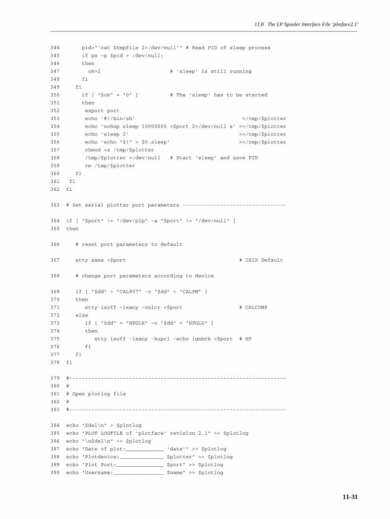
11.8 The LP Spooler Interface File ‘plotface2.1’
344 pid="‘cat $tmpfile 2>/dev/null‘" # Read PID of sleep process
345 if ps -p $pid > /dev/null;
346 then
347 ok=1 # ’sleep’ is still running
348 fi
349 fi
350 if [ "$ok" = "0" ] # The ’sleep’ has to be started
351 then
352 export port
353 echo ’#!/bin/sh’ >/tmp/$plotter
354 echo ’nohup sleep 10000000 <$port 2>/dev/null &’ >>/tmp/$plotter
355 echo ’sleep 2’ >>/tmp/$plotter
356 echo ’echo "$!" > $0.sleep’ >>/tmp/$plotter
357 chmod +x /tmp/$plotter
358 /tmp/$plotter >/dev/null # Start ’sleep’ and save PID
359 rm /tmp/$plotter
360 fi
361 fi
362 fi
363 # Set serial plotter port parameters ---------------------------------
364 if [ "$port" != "/dev/plp" -a "$port" != "/dev/null" ]
365 then
366 # reset port parameters to default
367 stty sane <$port # IRIX Default
368 # change port parameters according to device
369 if [ "$dd" = "CAL907" -o "$dd" = "CALPM" ]
370 then
371 stty ixoff -ixany -onlcr <$port # CALCOMP
372 else
373 if [ "$dd" = "HPGLR" -o "$dd" = "HPGLU" ]
374 then
375 stty ixoff -ixany -hupcl -echo ignbrk <$port # HP
376 fi
377 fi
378 fi
379 #---------------------------------------------------------------------
380 #
381 # Open plotlog file
382 #
383 #---------------------------------------------------------------------
384 echo "$del\n" > $plotlog
385 echo "PLOT LOGFILE of ’plotface’ revision 2.1" >> $plotlog
386 echo "\n$del\n" >> $plotlog
387 echo "Date of plot:____________ ‘date‘" >> $plotlog
388 echo "Plotdevice:______________ $plotter" >> $plotlog
389 echo "Plot Port:_______________ $port" >> $plotlog
390 echo "Username:________________ $name" >> $plotlog
11-31

11.8 The LP Spooler Interface File ‘plotface2.1’
391 echo "Plotfile:________________ $pfile" >> $plotlog
392 echo "LP-ID:___________________ $seqid" >> $plotlog
393 echo "Options:_________________ $options" >> $plotlog
394 echo "\n$del\n" >> $plotlog
395 #---------------------------------------------------------------------
396 #---------------------------------------------------------------------
397 #
398 # (1) CONVERT APPLICATION SPECIFIC PLOTFILE FORMAT TO UNIPLOT (NPF)
399 #
400 #---------------------------------------------------------------------
401 #---------------------------------------------------------------------
402 # Is the plotfile readable? If not, exit ...
403 if [ ! -r $pfile ]
404 then
405 echo "Can not read the plotfile! Abort plot-request ..." \
>> $plotlog
406 echo "\n$del" >> $plotlog
407 exit 6
408 fi
409 # AUTO-Detect type of plotfile (currently DDN, DUCT and NPFILE)
410 # Previously: ddnpf=‘strings $pfile | grep "ICEM PLOT FILE"‘
411 ddnpf=‘head -1 $pfile | grep "ICEM PLOT FILE"‘
412 if [ -n "$ddnpf" ]
413 then
414 echo "DDN plotfile conversion:\n" >> $plotlog
415 if [ ! -x $ddn2npf ]
416 then
417 if [ ! -x $plotserver/app2uni/‘basename $ddn2npf‘ ]
418 then
419 echo "Conversion program ‘basename $ddn2npf‘ not found" \
>> $plotlog
420 echo "in ‘dirname $ddn2npf‘ and $plotserver/app2uni !" \
>> $plotlog
421 echo "Abort plot-request ...\n\n$del" >> $plotlog
422 exit 7
423 else
424 echo "Conversion program $ddn2npf not found, but" \
>> $plotlog
425 echo "$plotserver/app2uni/‘basename $ddn2npf‘." \
>> $plotlog
426 echo "Plotface takes this program ...\n\n" >> $plotlog
427 ddn2npf="$plotserver/app2uni/‘basename $ddn2npf‘"
428 fi
429 fi
430 $ddn2npf i=$pfile o=NPFILE fmt=NPFILE $optprms >> $plotlog 2>&1
431 else
432 # Previously: dctpf=‘strings $pfile | grep "DOGPLOT"‘
433 dctpf=‘head -1 $pfile | strings | grep "DOGPLOT"‘
434 if [ -n "$dctpf" ]
435 then
11-32
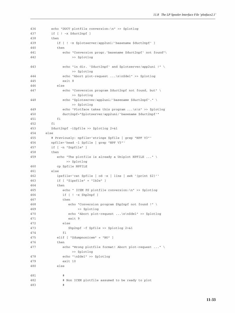
11.8 The LP Spooler Interface File ‘plotface2.1’
436 echo "DUCT plotfile conversion:\n" >> $plotlog
437 if [ ! -x $duct2npf ]
438 then
439 if [ ! -x $plotserver/app2uni/‘basename $duct2npf‘ ]
440 then
441 echo "Conversion progr.‘basename $duct2npf‘ not found"\
442 >> $plotlog
443 echo "in dir. ‘$duct2npf‘ and $plotserver/app2uni !" \
>> $plotlog
444 echo "Abort plot-request ...\n\n$del" >> $plotlog
445 exit 8
446 else
447 echo "Conversion program $duct2npf not found, but" \
>> $plotlog
448 echo "$plotserver/app2uni/‘basename $duct2npf‘." \
>> $plotlog
449 echo "Plotface takes this program ...\n\n" >> $plotlog
450 duct2npf="$plotserver/app2uni/‘basename $duct2npf‘"
451 fi
452 fi
453 $duct2npf -i$pfile >> $plotlog 2>&1
454 else
455 # Previously: npfile=‘strings $pfile | grep "NPF V3"‘
456 npfile=‘head -1 $pfile | grep "NPF V3"‘
457 if [ -n "$npfile" ]
458 then
459 echo "The plotfile is already a Uniplot NPFILE ..." \
>> $plotlog
460 cp $pfile NPFILE
461 else
462 ipsfile=‘cat $pfile | od -x | line | awk ’{print $2}’‘
463 if [ "$ipsfile" = "1b2e" ]
464 then
465 echo " ICEM PS plotfile conversion:\n" >> $plotlog
466 if [ ! -x $hp2npf ]
467 then
468 echo "Conversion program $hp2npf not found !" \
469 >> $plotlog
470 echo "Abort plot-request ...\n\n$del" >> $plotlog
471 exit 9
472 else
473 $hp2npf -f $pfile >> $plotlog 2>&1
474 fi
475 elif [ "$dumpnonicem" = "NO" ]
476 then
477 echo "Wrong plotfile format! Abort plot-request ..." \
>> $plotlog
478 echo "\n$del" >> $plotlog
479 exit 10
480 else
481 #
482 # Non ICEM plotfile assumed to be ready to plot
483 #
11-33
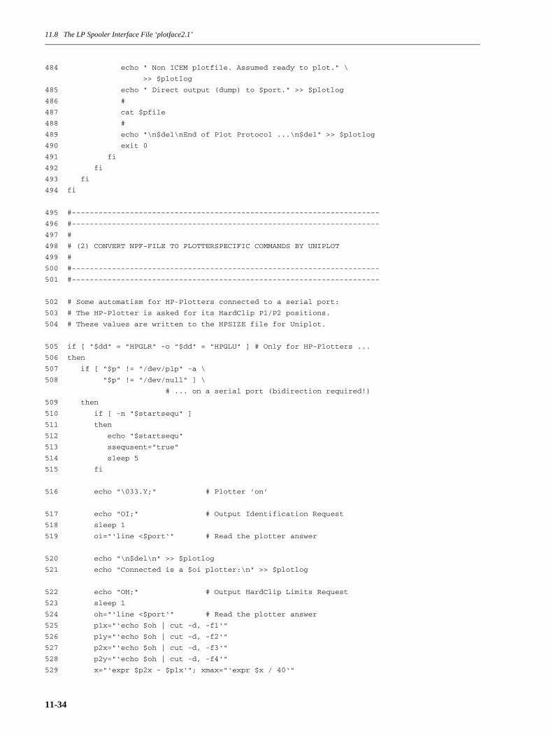
11.8 The LP Spooler Interface File ‘plotface2.1’
484 echo " Non ICEM plotfile. Assumed ready to plot." \
>> $plotlog
485 echo " Direct output (dump) to $port." >> $plotlog
486 #
487 cat $pfile
488 #
489 echo "\n$del\nEnd of Plot Protocol ...\n$del" >> $plotlog
490 exit 0
491 fi
492 fi
493 fi
494 fi
495 #---------------------------------------------------------------------
496 #---------------------------------------------------------------------
497 #
498 # (2) CONVERT NPF-FILE TO PLOTTERSPECIFIC COMMANDS BY UNIPLOT
499 #
500 #---------------------------------------------------------------------
501 #---------------------------------------------------------------------
502 # Some automatism for HP-Plotters connected to a serial port:
503 # The HP-Plotter is asked for its HardClip P1/P2 positions.
504 # These values are written to the HPSIZE file for Uniplot.
505 if [ "$dd" = "HPGLR" -o "$dd" = "HPGLU" ] # Only for HP-Plotters ...
506 then
507 if [ "$p" != "/dev/plp" -a \
508 "$p" != "/dev/null" ] \
# ... on a serial port (bidirection required!)
509 then
510 if [ -n "$startsequ" ]
511 then
512 echo "$startsequ"
513 ssequsent="true"
514 sleep 5
515 fi
516 echo "\033.Y;" # Plotter ’on’
517 echo "OI;" # Output Identification Request
518 sleep 1
519 oi="‘line <$port‘" # Read the plotter answer
520 echo "\n$del\n" >> $plotlog
521 echo "Connected is a $oi plotter:\n" >> $plotlog
522 echo "OH;" # Output HardClip Limits Request
523 sleep 1
524 oh="‘line <$port‘" # Read the plotter answer
525 p1x="‘echo $oh | cut -d, -f1‘"
526 p1y="‘echo $oh | cut -d, -f2‘"
527 p2x="‘echo $oh | cut -d, -f3‘"
528 p2y="‘echo $oh | cut -d, -f4‘"
529 x="‘expr $p2x - $p1x‘"; xmax="‘expr $x / 40‘"
11-34
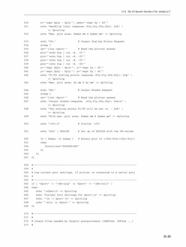
11.8 The LP Spooler Interface File ‘plotface2.1’
530 y="‘expr $p2y - $p1y‘"; ymax="‘expr $y / 40‘"
531 echo "HardClip limit response (P1x,P1y,P2x,P2y): $oh" \
>> $plotlog
532 echo "Max. plot area: $xmax mm X $ymax mm" >> $plotlog
533 echo "OP;" # Output Scaling Points Request
534 sleep 1
535 op="‘line <$port‘" # Read the plotter answer
536 p1x="‘echo $op | cut -d, -f1‘"
537 p1y="‘echo $op | cut -d, -f2‘"
538 p2x="‘echo $op | cut -d, -f3‘"
539 p2y="‘echo $op | cut -d, -f4‘"
540 x="‘expr $p2x - $p1x‘"; x="‘expr $x / 40‘"
541 y="‘expr $p2y - $p1y‘"; y="‘expr $y / 40‘"
542 echo "P1/P2 scaling points response (P1x,P1y,P2x,P2y): $op" \
>> $plotlog
543 echo "Max. plot area: $x mm X $y mm" >> $plotlog
544 echo "OW;" # Output Window Request
545 sleep 1
546 ow="‘line <$port‘" # Read the plotter answer
547 echo "Output window response (P1x,P1y,P2x,P2y): $ow\n" \
>> $plotlog
548 echo "The scaling points P1/P2 will be set to : $oh" \
>> $plotlog
549 echo "With max. plot area: $xmax mm X $ymax mm" >> $plotlog
550 echo "\033.Z" # Plotter ’off’
551 echo "$oh" > HPSIZE # Set up of HPSIZE with the OH-values
552 if [ $xmax -lt $ymax ] # Rotate plot if ((P2x-P1x)<(P2y-P1y))
553 then
554 directive2="ROTATE=ON*"
555 fi
556 fi
557 fi
558 #---------------------------------------------------------------------
559 #
560 # Log current port settings, if plotter is connected to a serial port
561 #
562 #---------------------------------------------------------------------
563 if [ "$port" != "/dev/plp" -a "$port" != "/dev/null" ]
564 then
565 echo "\n$del\n" >> $plotlog
566 echo "Current Port Settings for $port:\n" >> $plotlog
567 echo "‘ls -l $port‘\n" >> $plotlog
568 echo "‘stty -a <$port‘" >> $plotlog
569 fi
570 #---------------------------------------------------------------------
571 #
572 # Create files needed by Uniplot postprocessor (INPFILE, OPFILE ...)
573 #
11-35

11.8 The LP Spooler Interface File ‘plotface2.1’
574 #---------------------------------------------------------------------
575 # Create input directive file for ’unipst’
576 rm INPFILE 2>/dev/null # Clear input directive file
577 if [ -n "$inpdirs" ]
578 then
579 echo "$inpdirs" > INPFILE
580 fi
581 if [ "$directive2" != "NONE*" ]
582 then
583 echo "$directive2" >> INPFILE # Directive for ’unipst’
584 fi
585 echo "$directive1" >> INPFILE # Directive for ’unipst’
586 # Create operation file for ’unipst’
587 echo "INPFILE" > OPFILE # Source of input directives
588 echo "/dev/tty" >> OPFILE # Operator output
589 echo "NPFILE" >> OPFILE # Name of Neutral Picture Format file
590 echo "PLOTF" >> OPFILE # Plotfile on disk
591 echo "$d" >> OPFILE # Device keyword
592 echo "CM" >> OPFILE # Measurement (INCH, CM)
593 echo "OFFLINE" >> OPFILE # Plot disposition
594 echo "NO" >> OPFILE # Banner (NO or text)
595 echo "$name" >> OPFILE # User name
596 echo "DHCFILE" >> OPFILE # Device Hardware Characteristics File
597 echo " " >> OPFILE # Parameter lf1 (local font 1)
598 echo " " >> OPFILE # Parameter lf2 (local font 2)
599 echo "DHCEXT" >> OPFILE # Extended DHCFILE
600 #
601 echo "\n$del\n" >> $plotlog
602 echo "Content of ’INPFILE’:\n" >> $plotlog
603 /bin/cat INPFILE >> $plotlog
604 echo "\n$del\n" >> $plotlog
605 echo "Content of ’OPFILE’:\n" >> $plotlog
606 /bin/cat OPFILE >> $plotlog
607 echo "\n$del\n" >> $plotlog
608 if [ -f HPSIZE ]
609 then
610 echo "Content of ’HPSIZE’:\n" >> $plotlog
611 /bin/cat HPSIZE >> $plotlog
612 echo "\n$del\n" >> $plotlog
613 fi
614 # Copy the DHCFILE or DHCEXT file into current directory for ’unipst’
615 if [ -f $plotserver/uniplot/$dd/DHCFILE ]
616 then
617 cp $plotserver/uniplot/$dd/DHCFILE ./
11-36
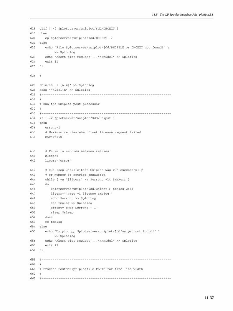
11.8 The LP Spooler Interface File ‘plotface2.1’
618 elif [ -f $plotserver/uniplot/$dd/DHCEXT ]
619 then
620 cp $plotserver/uniplot/$dd/DHCEXT ./
621 else
622 echo "File $plotserver/uniplot/$dd/DHCFILE or DHCEXT not found!" \
>> $plotlog
623 echo "Abort plot-request ...\n\n$del" >> $plotlog
624 exit 11
625 fi
626 #
627 /bin/ls -l [A-Z]* >> $plotlog
628 echo "\n$del\n" >> $plotlog
629 #---------------------------------------------------------------------
630 #
631 # Run the Uniplot post processor
632 #
633 #---------------------------------------------------------------------
634 if [ -x $plotserver/uniplot/$dd/unipst ]
635 then
636 errcnt=1
637 # Maximum retries when float license request failed
638 maxerr=50
639 # Pause in seconds between retries
640 sleep=5
641 licerr="error"
642 # Run loop until either Uniplot was run successfully
643 # or number of retries exhausted
644 while [ -n "$licerr" -a $errcnt -lt $maxerr ]
645 do
646 $plotserver/uniplot/$dd/unipst > tmplog 2>&1
647 licerr="‘grep -i license tmplog‘"
648 echo $errcnt >> $plotlog
649 cat tmplog >> $plotlog
650 errcnt=‘expr $errcnt + 1‘
651 sleep $sleep
652 done
653 rm tmplog
654 else
655 echo "Uniplot pp $plotserver/uniplot/$dd/unipst not found!" \
>> $plotlog
656 echo "Abort plot-request ...\n\n$del" >> $plotlog
657 exit 12
658 fi
659 #---------------------------------------------------------------------
660 #
661 # Process PostScript plotfile PLOTF for fine line width
662 #
663 #---------------------------------------------------------------------
11-37

11.8 The LP Spooler Interface File ‘plotface2.1’
664 # If the ’POSTSC’ device driver was used, substitute the setlinewidth
665 # PostScript command by a mathematic expression to get line width
666 # steps by 0.05 mm.
667 if [ "$dd" = "POSTSC" ]
668 then
669 if [ ! -f ./PLOTF ]
670 then
671 echo "Plotfile ’PLOTF’ expected, but not found!" >> $plotlog
672 echo "Abort plot-request ...\n\n$del" >> $plotlog
673 exit 13
674 fi
675 mv PLOTF PLOTF1
676 sed ’s/setlinewidth/3.6 mul 14.4 add 25.4 div setlinewidth/’ PLOTF1 > PLOTF
677 #
678 # Use the following line instead, if hair line width is required.
679 # sed ’s/setlinewidth/0 mul setlinewidth/’ PLOTF1 > PLOTF
680 #
681 rm PLOTF1
682 fi
683 #---------------------------------------------------------------------
684 #
685 # Add start/endsequences to the plotfile PLOTF
686 #
687 #---------------------------------------------------------------------
688 if [ ! -f ./PLOTF ]
689 then
690 echo "Plotfile ’PLOTF’ expected, but not found!" >> $plotlog
691 echo "Abort plot-request ...\n\n$del" >> $plotlog
692 exit 14
693 fi
694 if [ -n "$startsequ" -a "$ssequsent" = "false" ]
695 then
696 mv PLOTF PLOTF1
697 echo "$startsequ" > PLOTF
698 cat PLOTF1 >> PLOTF # Concatenate start sequence with the plotfile
699 rm PLOTF1
700 fi
701 if [ -n "$endsequ" ]
702 then
703 echo "$endsequ" >> PLOTF # Append defined end sequence to plotfile
704 fi
705 #---------------------------------------------------------------------
706 #
707 # Output or process the ready to plot plotfile PLOTF
708 #
709 #---------------------------------------------------------------------
710 /bin/cat ./PLOTF # No redirection! The LP-Spooler does it!
11-38
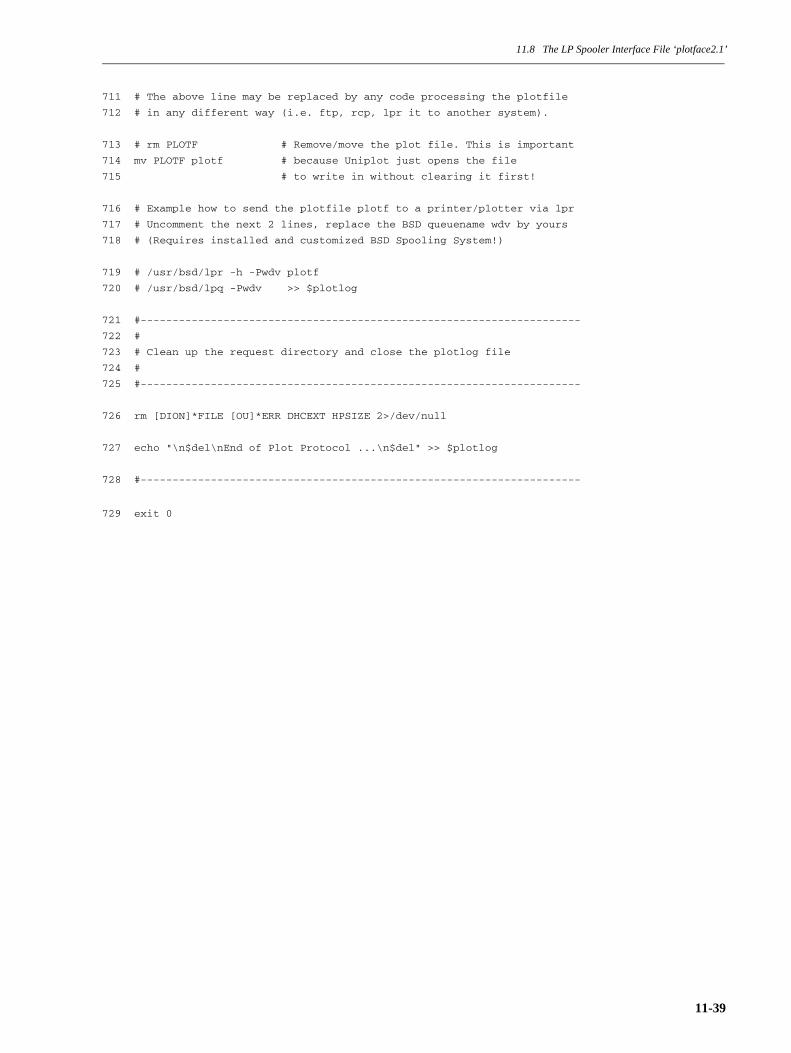
11.8 The LP Spooler Interface File ‘plotface2.1’
711 # The above line may be replaced by any code processing the plotfile
712 # in any different way (i.e. ftp, rcp, lpr it to another system).
713 # rm PLOTF # Remove/move the plot file. This is important
714 mv PLOTF plotf # because Uniplot just opens the file
715 # to write in without clearing it first!
716 # Example how to send the plotfile plotf to a printer/plotter via lpr
717 # Uncomment the next 2 lines, replace the BSD queuename wdv by yours
718 # (Requires installed and customized BSD Spooling System!)
719 # /usr/bsd/lpr -h -Pwdv plotf
720 # /usr/bsd/lpq -Pwdv >> $plotlog
721 #---------------------------------------------------------------------
722 #
723 # Clean up the request directory and close the plotlog file
724 #
725 #---------------------------------------------------------------------
726 rm [DION]*FILE [OU]*ERR DHCEXT HPSIZE 2>/dev/null
727 echo "\n$del\nEnd of Plot Protocol ...\n$del" >> $plotlog
728 #---------------------------------------------------------------------
729 exit 0
11-39

11.8 The LP Spooler Interface File ‘plotface2.1’
11-40

Index
Index
Aaddclient 7-1ascale 3-3, 9-8autoplot 3-8 – 3-9
CCAL907 2-1 – 2-2, 5-1 – 5-2, 5-4, 9-1, 9-4 – 9-6, 9-13, 11-4 – 11-
6, 11-17 – 11-19CALPM 11-19cancel 3-4, 3-6, 10-3Cartridge drive 4-1CD 9-11CDCL 11-6CGM 3-3Checksum 11-4chmod 3-3Client/server 2-1Customizing area 9-1, 9-3, 9-6, 9-8, 11-4 – 11-5, 11-8, 11-10
Dductuni 11-16
EEND OF CUSTOMIZING AREA 9-2End sequence 9-6 – 9-7, 11-10EOB 11-4Ethernet 2-1, 9-12
HHPGL 2-1 – 2-2, 3-2 – 3-3, 5-1 – 5-2, 5-4, 9-1, 9-4 – 9-7, 9-14, 11-
7 – 11-8, 11-10, 11-18, 11-20 – 11-21HPGL/2 2-1 – 2-2, 5-1 – 5-2, 5-4, 9-4 – 9-7, 11-7 – 11-8, 11-18,
11-20 – 11-21HPGLR 11-20HPGLU 11-20
IICEM DDN 3-3, 3-8, 3-11, 6-1 – 6-2, 11-5, 11-10, 11-16ICEM DUCT 3-3, 3-12, 6-1, 11-16ICEM Installer 4-1, 4-3 – 4-5, 4-7ICEM PlotServer Package 1-1 – 1-3, 2-1 – 3-1, 3-8, 3-11, 4-1, 4-4 –
4-6, 5-1, 5-4 – 6-1, 9-10, 10-1, 11-7, 11-18, 11-21ICEM SURF 3-3, 3-11, 11-16ICEMview 1-1, 3-4 – 3-6, 3-11, 10-3Icon Catalog 3-4Impressario 2-2, 3-8, 5-1, 11-15 – 11-16IndigoMagic Desktop 1-1, 3-4Installation 1-1, 4-3, 5-1, 9-10 – 9-11, 11-1IRIS WorkSpace 1-1IRIX 4.x 1-1, 3-4, 5-3, 6-2, 9-11IRIX 5.x 1-1, 3-3 – 3-4, 5-1, 9-11, 11-21
KKeywords 9-5, 9-8, 9-13 – 9-14, 11-5, 11-8 – 11-10, 11-17 – 11-18keywords 9-13
LLocal 5-3 – 5-4, 9-12lp 3-1 – 3-3, 3-5 – 3-6, 3-8 – 3-9, 3-11 – 4-1, 4-4, 5-1 – 5-2, 5-4,
6-2, 7-1, 8-1, 9-1, 9-8, 9-10, 9-12, 10-1, 10-3, 11-6lp_autodetect 3-6lpadmin 3-2lpstat 3-1 – 3-2, 3-4, 3-6, 5-2lputil 2-2, 5-1, 9-4
MManual
Organization 0-1mknetpr 2-2, 7-1 – 7-2
NNetwork 5-3, 7-1 – 7-2Network interface 3-2NPFILE 3-3, 3-11, 9-1, 11-16 – 11-17
Ooptim 11-16
PP1/P2 3-3, 11-7Paper tray 11-14Parallel 1-1, 2-1PCL 2-2, 3-8, 9-6 – 9-7, 11-15Pen attributes 9-6, 11-7, 11-11, 11-13Plot server 1-2 – 1-3, 2-1 – 3-5, 4-5 – 4-6, 5-1, 6-1, 6-4 – 7-2, 10-
1, 10-3Plot_server 7-1plota3.com 3-12plota4.com 3-12plotface 2-1 – 2-2, 3-2 – 3-3, 3-8, 4-4, 5-1 – 5-2, 5-4, 6-2, 8-1, 9-1
– 9-3, 9-6 – 9-12, 10-1, 11-5 – 11-6, 11-16, 11-21 – 11-22
plotface2.0 9-1 – 9-2, 9-4 – 9-5plotlog 2-2, 3-3, 3-5, 6-2, 9-1 – 9-2, 10-1 – 10-3plotter_configuration 3-11Postprocessor 9-1, 9-4 – 9-5, 9-8, 9-12 – 9-14, 11-4 – 11-5, 11-7,
11-13, 11-17 – 11-18POSTSC 11-21PostScript 2-1 – 2-2, 5-1 – 5-2, 5-4, 9-4 – 9-6, 9-10, 10-3, 11-14 –
11-16Printer Manager 2-2, 5-1 – 5-4, 7-1 – 8-1, 9-4, 11-21Printserver Box 2-1PTC.Setup Program 4-6
RRaster formats 2-2rmprinter 8-1rot 3-3, 9-8, 10-2
SSerial 1-1, 2-1START OF CUSTOMIZING AREA 9-2Start sequence 9-7, 11-6, 11-14Sync 11-4
Ttape9 3-3, 3-9, 11-16tar 4-1telinit 5-2
Index-1

Index
TIFF 2-2tst_plotter 2-2, 4-4, 6-1 – 6-2, 10-3
UUniplot 1-2, 3-11, 4-4, 9-1, 9-4 – 9-6, 9-8, 9-10, 9-12 – 9-14, 10-1,
11-4 – 11-5, 11-15 – 11-18userlib 3-12
VVector formats 2-2, 11-15
WWorkSpace 1-1, 3-4
Index-2