Ice Sheet Motion Speckle tracking. Velocity measurement techniques Day 1 Day 24 Feature Retracking...
23
Ice Sheet Motion Speckle tracking
-
date post
22-Dec-2015 -
Category
Documents
-
view
215 -
download
0
Transcript of Ice Sheet Motion Speckle tracking. Velocity measurement techniques Day 1 Day 24 Feature Retracking...

Ice Sheet Motion
Speckle tracking

Velocity measurement techniques
Day 1
Day 24
Feature Retracking
100 mDay 1 Day 24
10 m
Day 1 Day 24
10 m
InSAR Speckle Retracking

Speckle Geometry

1
1
2
1
21
x
2/1222
)sin()cos(
))cos()sin()sin()(cos(
)90cos(
)cos(baseline parallel
chosen) slope negative (for the )sin(
)cos(
directionazimuth in the definitionby is Since
ntdisplacememotion ice )(
yzr
rr
r
r
rz
ry
ax
zyx
So
SrSrD
SrD
B
SrD
SrD
and
Range direction only

periodrepeatSpeed
So
Again
Sr
SaBp
Bpce
and
SrSa
This
SrSa
zyx
ary
ax
yxy
yxz
365
)(
)cos(*)sin(
)cos(**
and sin
)cos(**)sin(
nts.displaceme horizontal
the tocompared large is rateon accumulati thewhere
casesin invalid is and assumptionimportant an is
**
slope surface the toparallel flows ice that theAssume
2/1222
1
1r

Preprocessing

Doppler Overlap
(See if you can use the image data to compute doppler spectra)

Velocity Processing

Azimuth Corrections• Azimuth pixel spacing goes as prf as well as orbit height, terrain elevation, look angle
and latitude. Consequently two slightly different orbits will have slightly different azimuth spacings given approximately by
For a purely vertical separation, corresponding to about 14 m in height, the azimuthDisplacement will change about 3 parts in 10^6. There will be an accumulating Error such that after about 500 km, the azimuth will be incorrect by a measurable .3 pixels.

Comparisons

Coherence Streaks
An early incorrect idea

Ionospheric Streaks
• For C-band Radarsat, A SAR footprint is illuminated for about 0.5 sec. The satellite travels about 3.5 km.
• If the integrated electron density changes along the line of sight, while the footprint is illuminated, then the phase history built from about 600 pulses will be corrupted
• The consequence is incorrect azimuth placement.
• The effect is smaller in the range direction.

Streaks
• Idea tested by – Comparing streak density with ionospheric
activity– Simulations using a phase screen– Relationships to streak density and magnetic
poles

Option 1 – azimuth offset, range phase; azimuth offset, range offsets; ascending descending range;
Option 3 – only ascending descending range products.

Calibrating Phase Islands in the
Absence of Local Control

Phase and Range Offset

rr
rr
rr
rr
rr
r
r
Ln
L
RRL
Grouping
RRL
and
LRR
Where
rLRR
rLRR
R
For
4144
)4
(4
constants
)(4
So
rangein pixelnth theisr and size, pixel theisLr pixel,first the torange the tocorrespond R
speckleFor
retracking speckle with found biason registrati the
examplefor toequivalent biases geometric thecontainsIt scene. theacrossuniformly addedconstant some is
island, phase local ain phase unwrapped theis where
)(4
R
InSAR
'
'
02
010
02
010
01
02
0
2022
1011
0
012


Phase reconciliation

Information from Wrapped Phase
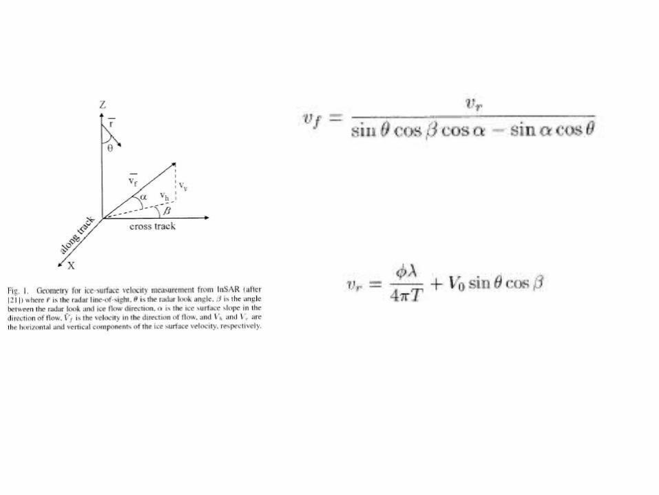

• Plug Vr into Vf and differentiate along flow direction
We assume that several terms are small: change in look direction is small; changes in flow directions are small for large glaciers over 0-30 km, Large scale strain rates not effected by surface slope.

Calculated Strain Rates