
ICE® Pile Driving Leads...used. The pile guide aligns the leads, hammer and drive cap with the...
18
Designed and manufactured in USA by ICE® World leader in cost-effective foundation equipment since 1974. WWW.ICEUSA.COM 888-ICE-USA1 Constant improvement and engineering progress make it necessary that ICE ® , Inc reserve the right to make specification changes without notice. Please consult ICE ® for the latest available information. High-strength structural tube front guide-rails for abrasion resistance. Braced rear tubes are structurally matched with front rails to provide equal moment capacity for both fore and aſt batter conditions. Rigid-bolted or pinned connections provide maximum stability. Available in various sections for maximum flexibility. All sections precision-fabricated in production jigs to maintain strict dimensional tolerances that ensure accurate connection and alignment. Fitted with full-length ladders for easy equipment access. Swinging, fixed, sliding and offshore configurations available. 20’’ through 66’’ sizes available. Engineered to provide maximum strength-to-weight ratio for superior pile rig performance. Rooster sheave Headblock with auger bracket Hydraulic spotter Boom point connector Durable - Economical - Versatile ICE® Pile Driving Leads
Transcript of ICE® Pile Driving Leads...used. The pile guide aligns the leads, hammer and drive cap with the...
Designed and manufactured in USA by ICE®World leader in cost-effective foundation equipment since 1974.
WWW.ICEUSA.COM888-ICE-USA1
Constant improvement and engineering progress make it necessary that ICE®, Inc reserve the right to make specification changes without notice. Please consult ICE® for the latest available information.
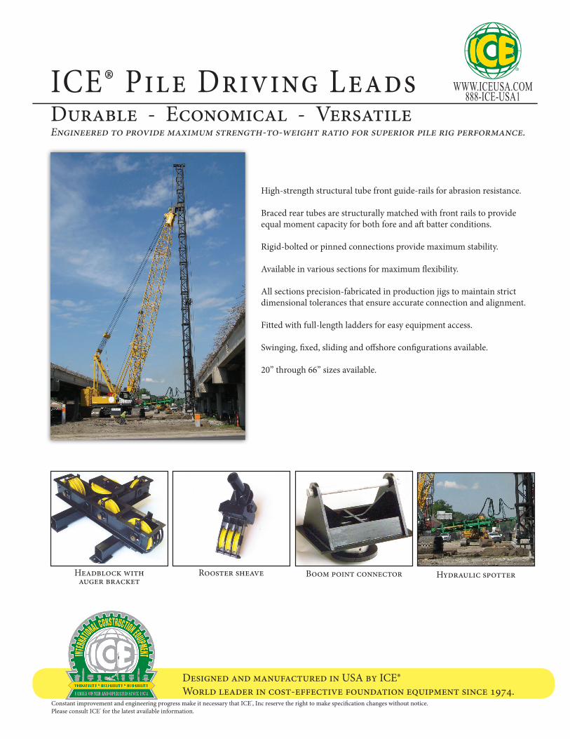
High-strength structural tube front guide-rails for abrasion resistance.
Braced rear tubes are structurally matched with front rails to provide equal moment capacity for both fore and aft batter conditions.
Rigid-bolted or pinned connections provide maximum stability.
Available in various sections for maximum flexibility.
All sections precision-fabricated in production jigs to maintain strict dimensional tolerances that ensure accurate connection and alignment.
Fitted with full-length ladders for easy equipment access.
Swinging, fixed, sliding and offshore configurations available.
20’’ through 66’’ sizes available.
Engineered to provide maximum strength-to-weight ratio for superior pile rig performance.
Rooster sheaveHeadblock with auger bracket
Hydraulic spotterBoom point connector
Durable - Economical - VersatileICE® Pile Driving Leads

©International Construction Equipment, Inc. All rights reserved. January 2015.
Designed and manufactured in USA by ICE®World leader in cost-effective foundation equipment since 1974.
WWW.ICEUSA.COM888-ICE-USA1
Swinging Fixed, Underhung Fixed, Extended
Cable Hung OffshoreSliding, Extended
ICE® Pile Driving LeadsDurable - Economical - Versatile

Designed and manufactured in USA by ICE®World leader in cost-effective foundation equipment since 1974.
WWW.ICEUSA.COM888-ICE-USA1
Constant improvement and engineering progress make it necessary that ICE®, Inc reserve the right to make specification changes without notice. Please consult ICE® for the latest available information.
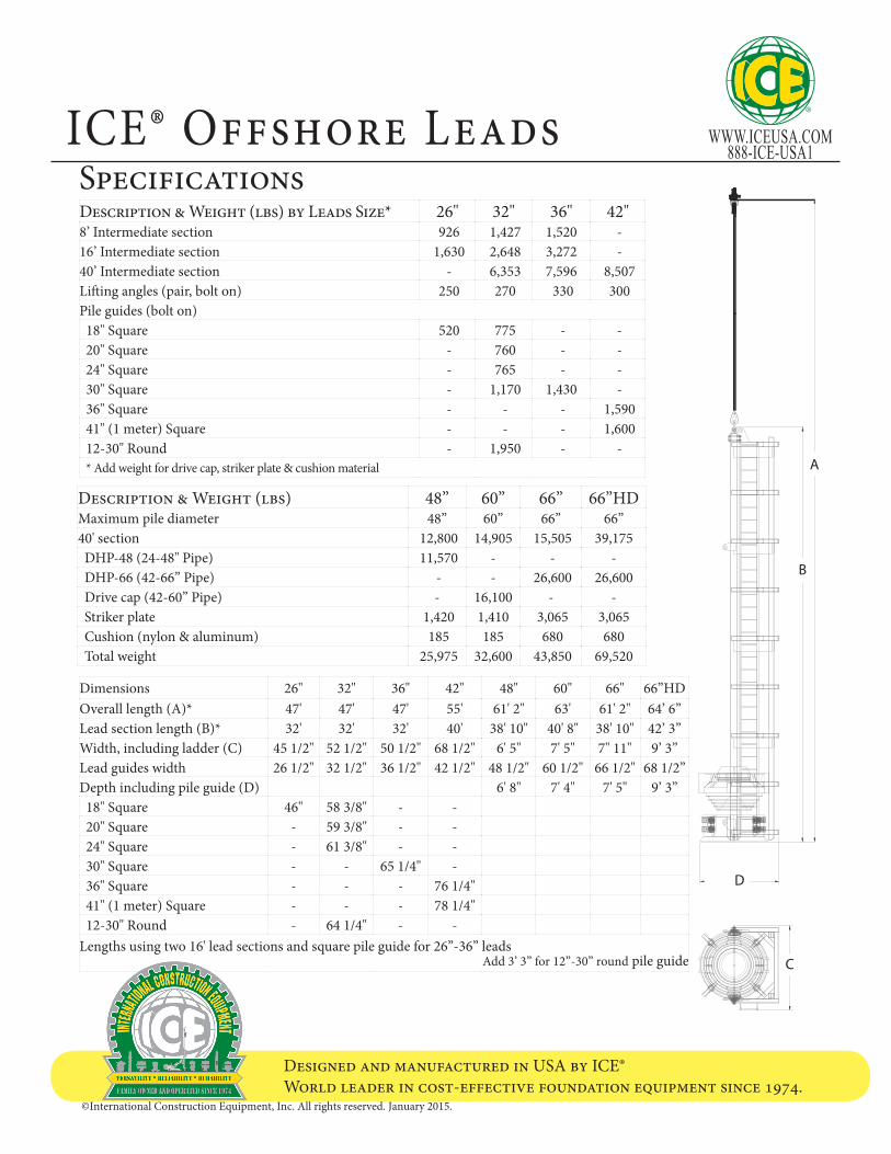
Offshore leads are hung from the crane boom by a crane line. The bottom of the leads has a guide that slides over the top of the pile. The crane line and boom are positioned to hold the leads plumb or at the desired batter in line with the pile.
Offshore leads are generally used with larger hammers and piles. The pile must have its own support structure.
Offshore leads are assembled from three components – a leads section, lifting gear, and a pile guide. The leads section guides the pile hammer and drive cap. The lifting gear supports the leads section and provides spacing for the ram and has a starting line if a diesel hammer is used. The pile guide aligns the leads, hammer and drive cap with the pile.
CAUTIONICE® leads are designed and built for normal hammers piles and driving conditions. If unusual ham-mers, piles or driving conditions are encountered or if any question about specific job situation arises, contact ICE before proceeding with pile driving operations.
ICE® Offshore Leads
©International Construction Equipment, Inc. All rights reserved. January 2015.
Designed and manufactured in USA by ICE®World leader in cost-effective foundation equipment since 1974.
WWW.ICEUSA.COM888-ICE-USA1
Description & Weight (lbs) by Leads Size* 26" 32" 36" 42"8’ Intermediate section 926 1,427 1,520 - 16’ Intermediate section 1,630 2,648 3,272 - 40’ Intermediate section - 6,353 7,596 8,507 Lifting angles (pair, bolt on) 250 270 330 300 Pile guides (bolt on)18" Square 520 775 - - 20" Square - 760 - - 24" Square - 765 - - 30" Square - 1,170 1,430 - 36" Square - - - 1,590 41" (1 meter) Square - - - 1,600 12-30" Round - 1,950 - - * Add weight for drive cap, striker plate & cushion material
C
D
A
B
Description & Weight (lbs) 48” 60” 66” 66”HDMaximum pile diameter 48” 60” 66” 66”40' section 12,800 14,905 15,505 39,175DHP-48 (24-48" Pipe) 11,570 - - -DHP-66 (42-66” Pipe) - - 26,600 26,600Drive cap (42-60” Pipe) - 16,100 - -Striker plate 1,420 1,410 3,065 3,065Cushion (nylon & aluminum) 185 185 680 680Total weight 25,975 32,600 43,850 69,520
ICE® Offshore LeadsSpecifications
Dimensions 26" 32" 36" 42" 48" 60" 66" 66”HDOverall length (A)* 47' 47' 47' 55' 61' 2" 63' 61' 2" 64’ 6”Lead section length (B)* 32' 32' 32' 40' 38' 10" 40' 8" 38' 10" 42’ 3”Width, including ladder (C) 45 1/2" 52 1/2" 50 1/2" 68 1/2" 6' 5" 7' 5" 7" 11" 9’ 3”Lead guides width 26 1/2" 32 1/2" 36 1/2" 42 1/2" 48 1/2" 60 1/2" 66 1/2" 68 1/2”Depth including pile guide (D) 6' 8" 7' 4" 7' 5" 9’ 3”18" Square 46" 58 3/8" - -20" Square - 59 3/8" - -24" Square - 61 3/8" - -30" Square - - 65 1/4" -36" Square - - - 76 1/4"41" (1 meter) Square - - - 78 1/4"12-30" Round - 64 1/4" - -
Lengths using two 16' lead sections and square pile guide for 26”-36” leads Add 3’ 3” for 12”-30” round pile guide

Designed and manufactured in USA by ICE®World leader in cost-effective foundation equipment since 1974.
WWW.ICEUSA.COM888-ICE-USA1
Constant improvement and engineering progress make it necessary that ICE®, Inc reserve the right to make specification changes without notice. Please consult ICE® for the latest available information.
HEADBLOCK
INTERMEDIATE WITHBOOM-POINT CONNECTOR
INTERMEDIATE
INTERMEDIATE
INTERMEDIATE
INTERMEDIATE
INTERMEDIATE
BOOM-POINT CONNECTOR
ROOSTER SHEAVE
SPOTTER
Fixed, extended leads extend above the boom-point. They are connected to the boom-point with a swivel connection to allow movement in the fore-aft and side-to-side directions. A spotter connects the bottom of the leads to the front of the crane. A headblock directs the crane lines over the top of the leads. A rooster sheave at the boom-point guides the lines to the headblock.
Extended leads require only a two-line crane (pile & hammer) although a third auxilary line may be used if desired. Excellent speed, control and accuracy are possible in positioning the leads. Side-to-side as well as fore and aft adjustment is possible. A shorter boom may be used. However, extended leads are more expensive and require more time to set up.
COMPONENTSICE® fixed extended leads are assembled from several components—4, 8, 16, or 40-foot intermediate sections, a headblock, a boom-point connector, a rooster sheave and a spotter.
Various intermediate sections have the boom-point connection positioned to allow vertical positioning of the leads. Multiple intermediate sections may be used both above and below the section to allow complete flexibility in boom and lead lengths.
The boom-point connector attaches the boom-point intermediate section to the boom-point of the crane. The connector permits full fore-aft and side-to-side movement.
The headblock, which carries the crane lines over the top of the leads, is available with either 4 or 6 sheaves to handle either 2 or 3 lines. An optional auger side-sheave is available.
Model 101, 155 or 225 spotters are available to position the bottom of the leads.
ICE® Fixed, Extended Leads
Rooster sheaveHeadblock with auger bracket
Hydraulic spotterBoom point connector

©International Construction Equipment, Inc. All rights reserved. January 2015.
Designed and manufactured in USA by ICE®World leader in cost-effective foundation equipment since 1974.
WWW.ICEUSA.COM888-ICE-USA1
A B
C
D
F
E
G
20 in. 26 in. 32 in. 42 in.A 39.5 45.5 52.5 68.5B 35.5 41.5 48.5 64.5C 28.5 34.5 40.5 54.5D 20.5 26.5 32.5 42.5E 18.8 20.8 31 35F 8 8 8 8G 34.1 36.1 48.6 53.8
C
F
E
B
G
D
36 in.A -B 35.5C 43D 26E 21F 6G 62
Pile Gate Weight (lbs) 26 in 32 inPile gate arms without rollers 800 1,000Rollers for 12” pile - set of 8 280 -Rollers for 14” pile - set of 8 240 -Rollers for 16” pile - set of 8 200 320Rollers for 18” pile - set of 8 160 280Rollers for 20” pile - set of 8 - 240Rollers for 22” pile - set of 8 200Rollers for 24” pile - set of 8 - 160DISTANCE LEADS
ABOVE GROUND
I
X
WORKING RADIUS
DIST. FROM BOOM BUTT TO TIP
BOOMANGLE
BOOM LEN
GTH
SPOTTER LENGTH
DISTANCE SPOTTER UP BACK OF LEADS
LEN
GTH
OF L
EA
DS
UN
DER
BO
OM
Layout Consideration
ICE® Fixed, Extended Leads
Description & Weight (lbs) by Leads Size 26 in 32 in 36 in4’ Intermediate section 570 - -8’ Intermediate section 947 1,427 1,52016’ Intermediate section 1,660 2,648 3,27240’ Intermediate section 4,146 6,353 7,5962’ Fixed boom-point section 670 - -3’ Fixed boom-point section - 1,563 -40’ Fixed boom-point section - 9,157 11,070Boom-point connnector - 2 axis 1,150 1,150 1,150Roosted sheave ( 3 lines x 8” sheaves) - 2 axis 150 150 150Roosted sheave ( 3 lines x 8” sheaves) - 3 axis 200 200 200Roosted sheave ( 3 lines x 18” sheaves) - 2 axis 500 500 500Headblock (4 sheaves for 2 lines) 1,200 1,400 1,490Headblock (6 sheaves for 3 lines) 1,330 1,530 1,620Headblock with auger bracket (2 lines plus auger line) 1,750 2,000 -Side auger guides (weight per foot) 33 33 33Connecting bolts (weight per connection) 13 28 37
CAUTIONICE® leads are designed and built for normal hammers piles and driving conditions. If unusual hammers, piles or driving conditions are encountered or if any question about specific job situation arises, contact ICE before proceeding with pile driving operations.
Designed and manufactured in USA by ICE®World leader in cost-effective foundation equipment since 1974.
WWW.ICEUSA.COM888-ICE-USA1
Constant improvement and engineering progress make it necessary that ICE®, Inc reserve the right to make specification changes without notice. Please consult ICE® for the latest available information.
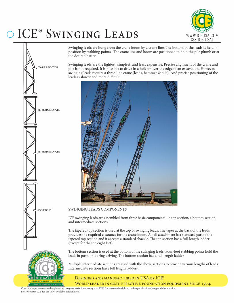
Swinging leads are hung from the crane boom by a crane line. The bottom of the leads is held in position by stabbing points. The crane line and boom are positioned to hold the pile plumb or at the desired batter.
Swinging leads are the lightest, simplest, and least expensive. Precise alignment of the crane and pile is not required. It is possible to drive in a hole or over the edge of an excavation. However, swinging leads require a three-line crane (leads, hammer & pile). And precise positioning of the leads is slower and more difficult.
SWINGING LEADS COMPONENTS
ICE swinging leads are assembled from three basic components—a top section, a bottom section, and intermediate sections.
The tapered top section is used at the top of swinging leads. The taper at the back of the leads provides the required clearance for the crane boom. A bail attachment is a standard part of the tapered top section and it accepts a standard shackle. The top section has a full-length ladder (except for the top eight feet). The bottom section is used at the bottom of the swinging leads. Four-foot stabbing points hold the leads in position during driving. The bottom section has a full length ladder.
Multiple intermediate sections are used with the above sections to provide various lengths of leads. Intermediate sections have full length ladders.
TAPERED TOP
INTERMEDIATE
INTERMEDIATE
BOTTOM
ICE® Swinging Leads

©International Construction Equipment, Inc. All rights reserved. January 2015.
Designed and manufactured in USA by ICE®World leader in cost-effective foundation equipment since 1974.
WWW.ICEUSA.COM888-ICE-USA1
Swinging leads components 20 in 26 in 32 in 36 in 42 in16’ Top Section with lifting bail assembly 1,170 1,495 2,288 - -32’ Top Section with lifting bail assembly 2,990 4,685 - -40’ Top Section with lifting bail assembly - - - 7,055 -Lifting angles (pair, bolt on) - - 270 330 3004’ Intermediate section - 570 - - -8’ Intermediate section 926 947 1,427 1,520 -16’ Intermediate section 1,630 1,660 2,648 3,272 -40’ Intermediate section - 4,146 6,353 7,596 8,5074’ Stab point bottom section 390 406 696 960 1,05020’ Stab point bottom section - 1,930 3,000 - -40’ Stab point bottom section - - - 7,094 -Side auger guides (weight per foot) 33 33 33 33 33Connecting bolts (weight per connection) 13 13 28 37 50
ICE sells and rents a full line of standard pile hammers, leads and accessories to meet a wide variety of job requirements. In addition, ICE engineers and production personnel are fully qualified to design and build special leads and accessories to meet unique and difficult job specifications.
An efficient, productive lead set-up is key to a profitable pile driving operation. Experi-enced ICE personnel are available to insure that the proper components are provided to achieve the optimum arrangement for each job.
A B
C
D
F
E
G
C
F
E
B
G
D
ICE® Swinging Leads20 in. 26 in. 32 in. 42 in.
A 39.5 45.5 52.5 68.5B 35.5 41.5 48.5 64.5C 28.5 34.5 40.5 54.5D 20.5 26.5 32.5 42.5E 18.8 20.8 31 35F 8 8 8 8G 34.1 36.1 48.6 53.8
36 in.A -B 35.5C 43D 26E 21F 6G 62
CAUTIONICE® leads are designed and built for normal hammers piles and driving conditions. If unusual hammers, piles or driving conditions are encountered or if any question about specific job situ-ation arises, contact ICE before proceeding with pile driving operations.
Designed and manufactured in USA by ICE®World leader in cost-effective foundation equipment since 1974.
WWW.ICEUSA.COM888-ICE-USA1
Constant improvement and engineering progress make it necessary that ICE®, Inc reserve the right to make specification changes without notice. Please consult ICE® for the latest available information.
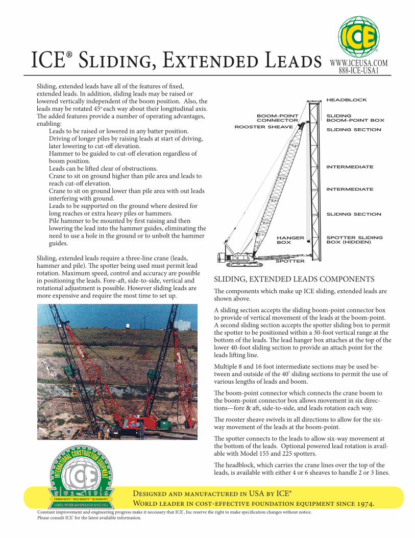
Sliding, extended leads have all of the features of fixed, extended leads. In addition, sliding leads may be raised or lowered vertically independent of the boom position. Also, the leads may be rotated 45o each way about their longitudinal axis. The added features provide a number of operating advantages, enabling:
Leads to be raised or lowered in any batter position.Driving of longer piles by raising leads at start of driving, later lowering to cut-off elevation. Hammer to be guided to cut-off elevation regardless of boom position. Leads can be lifted clear of obstructions.Crane to sit on ground higher than pile area and leads to reach cut-off elevation.Crane to sit on ground lower than pile area with out leads interfering with ground. Leads to be supported on the ground where desired for long reaches or extra heavy piles or hammers.Pile hammer to be mounted by first raising and then lowering the lead into the hammer guides, eliminating the need to use a hole in the ground or to unbolt the hammer guides.
Sliding, extended leads require a three-line crane (leads, hammer and pile). The spotter being used must permit lead rotation. Maximum speed, control and accuracy are possible in positioning the leads. Fore-aft, side-to-side, vertical and rotational adjustment is possible. However sliding leads are more expensive and require the most time to set up.
HEADBLOCK
SLIDING BOOM-POINT BOX
SLIDING SECTION
SLIDING SECTION
SPOTTER SLIDING BOX (HIDDEN)
BOOM-POINT CONNECTOR
ROOSTER SHEAVE
SPOTTER
HANGER BOX
INTERMEDIATE
INTERMEDIATE
SLIDING, EXTENDED LEADS COMPONENTS The components which make up ICE sliding, extended leads are shown above.
A sliding section accepts the sliding boom-point connector box to provide of vertical movement of the leads at the boom-point. A second sliding section accepts the spotter sliding box to permit the spotter to be positioned within a 30-foot vertical range at the bottom of the leads. The lead hanger box attaches at the top of the lower 40-foot sliding section to provide an attach point for the leads lifting line.
Multiple 8 and 16 foot intermediate sections may be used be-tween and outside of the 40’ sliding sections to permit the use of various lengths of leads and boom.
The boom-point connector which connects the crane boom to the boom-point connector box allows movement in six direc-tions—fore & aft, side-to-side, and leads rotation each way.
The rooster sheave swivels in all directions to allow for the six-way movement of the leads at the boom-point.
The spotter connects to the leads to allow six-way movement at the bottom of the leads. Optional powered lead rotation is avail-able with Model 155 and 225 spotters.
The headblock, which carries the crane lines over the top of the leads, is available with either 4 or 6 sheaves to handle 2 or 3 lines.
ICE® Sliding, Extended Leads

©International Construction Equipment, Inc. All rights reserved. January 2015.
Designed and manufactured in USA by ICE®World leader in cost-effective foundation equipment since 1974.
WWW.ICEUSA.COM888-ICE-USA1
ICE® sells and rents a full line of standard pile hammers, leads and accessories to meet a wide variety of job requirements. In addition, ICE® engineers and production team are fully qualified to design and build special leads & accessories to meet unique and difficult job specifications.
An efficient, productive lead set-up is key to a profitable pile driving operation. Experienced ICE® team members are available to insure
that the proper components are provided to achieve the optimum arrangement for each job.
ICE® Sliding, Extended LeadsA B
C
D
F
E
G
20 in. 26 in. 32 in. 42 in.A 39.5 45.5 52.5 68.5B 35.5 41.5 48.5 64.5C 28.5 34.5 40.5 54.5D 20.5 26.5 32.5 42.5E 18.8 20.8 31 35F 8 8 8 8G 34.1 36.1 48.6 53.8
C
F
E
B
G
D
36 in. A -B 35.5C 43D 26E 21F 6G 62
Pile Gate Weight (lbs) 26 in 32 inPile gate arms without rollers 800 1,000Rollers for 12” pile - set of 8 280 -Rollers for 14” pile - set of 8 240 -Rollers for 16” pile - set of 8 200 320Rollers for 18” pile - set of 8 160 280Rollers for 20” pile - set of 8 - 240Rollers for 22” pile - set of 8 200Rollers for 24” pile - set of 8 - 160
DISTANCE LEADS ABOVE GROUND
I
X
WORKING RADIUS
DIST. FROM BOOM BUTT TO TIP
BOOMANGLE
BOOM LENGTH
SPOTTER LENGTH
DISTANCE SPOTTER UP BACK OF LEADS
LEN
GTH
OF L
EA
DS
UN
DER
BO
OM
Layout Consideration
Description & Weight (lbs) by Leads Size 26 in 32 in 36 in4’ Intermediate section 570 - -8’ Intermediate section 947 1,427 1,52016’ Intermediate section 1,660 2,648 3,27240’ Intermediate section 4,146 6,353 7,5962’ Fixed boom-point section 670 - -3’ Fixed boom-point section - 1,563 -40’ Fixed boom-point section - 9,157 11,070Boom-point connnector - 2 axis 1,150 1,150 1,150Roosted sheave ( 3 lines x 8” sheaves) - 2 axis 150 150 150Roosted sheave ( 3 lines x 8” sheaves) - 3 axis 200 200 200Roosted sheave ( 3 lines x 18” sheaves) - 2 axis 500 500 500Headblock (4 sheaves for 2 lines) 1,200 1,400 1,490Headblock (6 sheaves for 3 lines) 1,330 1,530 1,620Headblock with auger bracket (2 lines plus auger line) 1,750 2,000 -Side auger guides (weight per foot) 33 33 33Connecting bolts (weight per connection) 13 28 3716’ long sliding box track with clamp-plates, bolts, nuts - 1,075 1,423Sliding boom point box - 897 1,115Lifting box with 3 sheaves - 448 616Spotter sliding box - 361 438
CAUTIONICE® leads are designed and built for normal hammers piles and driving conditions. If unusual hammers, piles or driving conditions are encoun-tered or if any question about specific job situa-tion arises, contact ICE before proceeding with pile driving operations.

Designed and manufactured in USA by ICE®World leader in cost-effective foundation equipment since 1974.
WWW.ICEUSA.COM888-ICE-USA1
Constant improvement and engineering progress make it necessary that ICE®, Inc reserve the right to make specification changes without notice. Please consult ICE® for the latest available information.
Swinging leads are hung from the crane boom by a crane line. The bottom of the leads is held in position by stabbing points. The crane line and boom are positioned to hold the pile plumb or at the desired batter.
Swinging leads are the lightest, simplest, and least expensive. Precise alignment of the crane and pile is not required. It is possible to drive in a hole or over the edge of an excavation. However, swinging leads require a three-line crane (leads, hammer & pile). And precise positioning of the leads is slower and more difficult.
SWINGING LEADS COMPONENTS ICE swinging leads are assembled from three basic components—a top section, a bottom section, and intermediate sections. The tapered top section is used at the top of swinging leads. The taper at the back of the leads provides the required clearance for the crane boom. A bail attachment is a standard part of the tapered top section and it accepts a standard shackle. The top section has a full-length ladder (except for the top eight feet).
The bottom section is used at the bottom of the swinging leads. Four-foot stabbing points hold the leads in position during driving. The bottom section has a full length ladder.
Multiple intermediate sections are used with the above sections to provide various lengths of leads. Intermediate sections have full length ladders.
TAPERED TOP
INTERMEDIATE
INTERMEDIATE
BOTTOM
ICE® Pin-Connected Swinging Leads

©International Construction Equipment, Inc. All rights reserved. January 2015.
Designed and manufactured in USA by ICE®World leader in cost-effective foundation equipment since 1974.
WWW.ICEUSA.COM888-ICE-USA1
ICE sells and rents a full line of standard pile hammers, leads and accessories to meet a wide variety of job requirements. In addition, ICE engineers and production personnel are fully qualified to design and build special leads and accessories to meet unique and difficult job specifications.
An efficient, productive lead set-up is key to a profitable pile driving operation. Experienced ICE personnel are available to insure that the proper components are provided to achieve the optimum arrangement for each job.
ICE® Pin-Connected Swinging LeadsA B
C
D
F
E
G
26 in. 32 in.A 45.5 52.5B 41.5 48.5C 34.5 40.5D 26.5 32.5E 20.8 31F 8 8G 36.1 48.6
Description & Weight (lbs) by Leads Size 26 in 32 in20’ Top Section with lifting bail assembly 2,450 2,47511’ Intermediate section 1,750 1,77020’ Intermediate section 2,850 2,88538’ Intermediate section 5,260 5,32020’ Stab point bottom section 2,450 2,475Lifting angles (pair, pin-on) 550 575Connecting pins (weight per connection) 18 18
CAUTIONICE® leads are designed and built for normal hammers piles and driving conditions. If unusual hammers, piles or driving conditions are encountered or if any question about specific job situation arises, contact ICE before proceeding with pile driving operations.

Designed and manufactured in USA by ICE®World leader in cost-effective foundation equipment since 1974.
WWW.ICEUSA.COM888-ICE-USA1
Constant improvement and engineering progress make it necessary that ICE®, Inc reserve the right to make specification changes without notice. Please consult ICE® for the latest available information.
High production and precise location of pile, especially on severe or compound batter.
Engine CAT C1.1Power 26 HP 19.7 kWOperating speed 3000 rpm 3000 rpmMaximum motors pressure 2000 psi 135 barMotors flow (no load) 18 gpm 70 lpmWeight (w/ full fluid & 1/2 fuel) 1315 lbs 595 kgLength 53 in 1350 mmWidth 41 in 1040 mmHeight 41 in 1040 mmHydraulic oil capacity 30 gal 110 litersFuel Capacity 15 gal 56 liters
ICE® Model 25
ICE® Spotters with ICE® Model 25 and 55 Power Units
ICE® MODEL 101 SPOTTERThe ICE® Model 101 light-duty, hydraulic lead spotter provides 21 ft (10’ hydraulic and 11’ manual) of fore-aft movement for batters up to 1:3 plus 6 ft of side-to-side move-ment (3’ each way from center) for plumbing. Standard items include rear, universal crane padeyes with pins, front lead connector plate, two-spool hydraulic valve, and 15’ hydraulic hoses connecting spotter to valve. Total weight = 3,000 lbs (1361 kg). Hydraulic requirements are 10 to 20 gpm at 1,500 psi.
ICE® MODEL 155 SPOTTERThe ICE® Model 155 medium-duty, hydraulic lead spotter provides 17 ft of hydraulic fore-aft movement for batters up to 1:3 plus 30° side-to-side movement (each way from center) for batters up to 1:4. Standard items include rear, universal crane padeyes with pins, front lead connector angles, two-spool hydraulic valve, and 15’ hydraulic hoses connecting spotter to valve. Optional items include a 30 degree (each way from center) front and lead rotator. Total weight = 6,000 lbs (2722kg). Hydraulic requirements are 10 to 20 gpm at 1,500 psi.
ICE® MODEL 225 SPOTTERThe ICE® Model 225 super-heavy-duty, hydraulic lead spotter provides 20 ft of hydraulic fore-aft movement for batters up to 1:3 plus 35° side-to-side movement (each way from center) for batters up to 1:3 plus 35° (each way from center) lead rotation. Standard items include rear, universal crane padeyes with pins, front lead connector box, three-spool hydraulic valve, and 15’ hydraulic hoses connecting spotter to valve. Total weight = 10,000 lbs (4536 kg). Hydraulic requirements are 10 to 20 gpm at 2,500 psi.
16’-5” Retracted, 37’-5” Extended18’-5” Retracted, 38’-5” Extended
16’-5” Retracted, 37’-5” Extended
3’3’
16’-5” Retracted, 37’-5” Extended
21’-5” Retracted, 41’-5” Extended
Engineered and fabricated to provide maximum strength-to-weight ratio for superior pile rig performance.Large-bore hydraulic cylinders provide smooth and easy pile positioning and maximum load capacity.Multi-segment design provides minimum retracted length for driving aft batters.Heavy-duty hydraulic lead rotators (optional on some models) provide precise pile positioning for compound batter piles.Rear pivot design (on some models) provides significant side-to-side movement for side batters to 1:4.
Engine CAT C2.2Power 50 HP 37.3 kWOperating speed 2800 rpm 2800 rpmMaximum motors pressure 3000 psi 190 barMotors flow (no load) 22 gpm 85 lpmWeight (w/ full fluid & 1/2 fuel) 2750 lbs 1247 kgLength 60 in 1525 mmWidth 44 in 1120 mmHeight 43 in 1090 mmHydraulic oil capacity 40 gal 150 litersFuel Capacity 17 gal 64 liters
ICE® Model 55
CAUTION: International Construction Equipment, Inc. (ICE®) claims no expertise in crane boom design and thus makes no representation as to the suitability of any crane boom to handle the imposed side and/or torsional leads resulting from batter piling operation. ICE®, therefore, advises the equipment user to consult with their crane boom manufacturer to obtain ap-proval for these loadings prior to erecting or operating a batter pile lead configuration.

Designed and manufactured in USA by ICE®World leader in cost-effective foundation equipment since 1974.
WWW.ICEUSA.COM888-ICE-USA1
Constant improvement and engineering progress make it necessary that ICE®, Inc reserve the right to make specification changes without notice. Please consult ICE® for the latest available information.
ICE® Spotters with ICE® Model 25 and 55 Power Units
Left Blank Intentionally

Designed and manufactured in USA by ICE®World leader in cost-effective foundation equipment since 1974.
WWW.ICEUSA.COM888-ICE-USA1
Constant improvement and engineering progress make it necessary that ICE®, Inc reserve the right to make specification changes without notice. Please consult ICE® for the latest available information.
ICE® drive cap system provides flexibility & cost savings for the contractor who drives various types/ sizes of piles or owns different sizes of pile hammers.
ICE® drive caps may be used with ICE® diesel & hydraulic impact hammers and many other manufacturers’ hammers.
The ICE® drive cap system includes the following four components: 1) Drive cap base which holds striker plate and cushion material in the top 2) Striker plate for single-acting diesels or striker block for hydraulic impact hammers 3) Cushion material - either nylon / aluminum or micarta / aluminum 4) Drive cap inserts for specific types of piles
Single piece drive caps are also available for larger hammers and piles.
Striker Plate
Aluminum
Aluminum
Cushion
Cushion
Drive Cap Base
Drive Cap Insert
©International Construction Equipment Inc. All rights reserved.
ICE® Drive Cap System

©International Construction Equipment, Inc. All rights reserved. January 2015.
Designed and manufactured in USA by ICE®World leader in cost-effective foundation equipment since 1974.
WWW.ICEUSA.COM888-ICE-USA1
DCP-16 700035 615 lbs Pipe and monotube to 16”
DCP-24 700037 1260 lbs 18” - 24” PipeDCP-30 700040 2530 lbs 24”, 26” & 30” Pipe
DCH-1 700032 780 lbs10”, 12” & 14” H-Beams12” Pipe PS28 & PS32 sheet piling
DCH-14 700358 955 lbs 12” & 14” H-Beams either wayDCH-18 700369 1405 lbs 16” & 18” H-Beams either way
DCH-2 700193 1010 lbs 14” H-Beams with 360° rotation
DCB-20 DCB-1 DCB-1HD DCB-2HD DCB-3HD700294 700005 700245 700236 700234
8” x 20” Leads 8” x 26” Leads 8” x 26” Leads 8” x 32” Leads 8” x 36” LeadsI-8, I-12, I-19 I-8, I-12, I-19 I-12, I-19, I-30 I-36, I-46, I-62 I-80, I-10030S, 32S, 42S 30S, 32S, 42S 60S, 80S 100S, 120S, 205S
115, IP2, IP3, IP4 160, 220, IP5, IP7 275Base DCB-20 760 lbs DCB-1 1065 lbs DCB-1HD 1245 lbs DCB-2HD 1670 lbs DCB-3HD 2340 lbs
Striker 4”x 16.5” 250 lbs 4”x 22.5” 460 lbs 4” x 22 1/2” 460 lbs 6” x 25” 845 lbs 8” x 30” 1410 lbsAluminum 1/2”x 16.5” 11 lbs 1/2”x 22.5” 20 lbs 1/2” x 22 1/2” (2) 40 lbs 1/2” x 25” (2) 50 lbs 1/2” x 30” (2) 72 lbs
Cushion 2”x 16.5” 19 lbs 2”x 22.5” 35 lbs 2” x 22 1/2” (2) 70 lbs 2” x 25” (2) 84 lbs 2” x 30” (2) 120 lbsCombined Weight 1040 lbs 1580 lbs 1815 lbs 2649 lbs 3942 lbs
DCC-10 700020 545 lbs 10” Square, round or octagonal concrete 10” H-Beams
DCC-12 700021 725 lbs12” Square, round or octagonal concrete12” H-Beams 10” Hexagonal concrete
DCC-14 700022 1080 lbs14” Square, round or octagonal concrete14” H-Beams 12” Hexagonal conrete
DCC-16 700023 1260 lbs 16” Square, round or octagonal concrete 14” Hexagonal conrete
DCC-18 700024 1415 lbs 18” Square, round or octagonal concrete 16” Hexagonal conrete
DCC-20 700025 1590 lbs 20” Square, round or octagonal concrete 18” Hexagonal conrete
DCC-24 700026 1775 lbs 24” Square, round or octagonal concrete 20” Hexagonal conrete
Drive Cap Bases
ICE® Drive Cap SystemDrive Cap Bases & Inserts
Inserts for H-Beams
Inserts for Pipe Piles
Inserts for Concrete Piles

Designed and manufactured in USA by ICE®World leader in cost-effective foundation equipment since 1974.
WWW.ICEUSA.COM888-ICE-USA1
Constant improvement and engineering progress make it necessary that ICE®, Inc reserve the right to make specification changes without notice. Please consult ICE® for the latest available information.
DCT-1 700042 700 lbs
Timber piles to 16”10” Square concrete14” Round concrete12” Pipe
DCS-1 700029 1165 lbs 12” Deep Z-sheet piles 8” x 26” Leads
DCS-2 700030 1130 lbs Flat sheet piles 8” x 26” Leads
DCS-3 700031 1870 lbs 14” Deep Z-sheet piles 8” x 32” Leads
DCS-4 700185 1280 lbs 16” Deep Z-sheet piles 8” x 26” Leads
DCS-5 700186 2365 lbs 18” Deep Z-sheet piles 8” x 32” Leads
DCA-1 2600 lbs ARBED Beam & sheet pile wall, wide-flange beams 8” x 26” Leads
ICE® Drive Cap SystemDrive Cap Bases & InsertsInserts for Sheet Piles
Inserts for Timber Piles

©International Construction Equipment, Inc. All rights reserved. January 2015.
Designed and manufactured in USA by ICE®World leader in cost-effective foundation equipment since 1974.
WWW.ICEUSA.COM888-ICE-USA1
Cap Item Application Leads Cushion Striker Cap Weight
DHCC-36 700266 36” Cylinder piles 8” x 42” 1/2”x30” AL (2)2”x30” Nylon (2) 8” x 30” 6,480 lbs
DHCC-54 700377 54’ Diam. x 6” wall max concrete cylinder piles 66” x 8” 1/2 x 27 AL (3)
1 x 27 Micarta (3) 12” x 27” 13,161 lbs
Cap Item Application Leads Cushion Striker Cap Weight
DHC-24 70004424” Concrete piles
8” x 32” 8” x 36” 1/2”x25” AL (2)
2”x25” Nylon (2)
6” x 25” 4,600 lbs
DHC-24HD 700368 8” x 32” 8” x 36” 8” x 25” 5,635 lbs
DHC-30 70007530” Concrete piles
8” x 36”
1/2”x30” AL (2) 2”x30” Nylon (2)
8” x 30” 4,485 lbs
DHC-30HD 700122 8” x 36” 8” x 42” 8” x 30” 5,870 lbs
DHC-36HD 700343 36” Concrete piles 8” x 42” 8” x 30” 7,450 lbs
Cap Item Application Leads Cushion Striker Cap Weight
DHP-42 700252 20” - 39” Pipe piles 8” x 42” 1/2” x 30” AL (2) 2” x 30” Nylon (2) 8” x 30” 5,200 lbs
DHP-48 700395 24, 30, 36, 42, 48” Pipe piles 8” x 48”8” x 54”
1/2 x 30 AL (3)1 x 30 Micarta (3) 8” x 30” 11,570 lbs
DHP-66 700375 36, 42, 54, 60, 66” Pipe piles 66” x 8”66” x 12”
1/2 x 37 AL (3)1 x 37 Micarta (3) 12” x 37” 26,600 lbs
ICE® Drive Cap SystemDrive CapsDrive Caps for Concrete
Drive Caps for Pipe
Drive Caps for Concrete Cylinder Piles