ICDE Project Report: Collection and Analysis of Common ...
54
Nuclear Safety NEA/CSNI/R(2013)2 June 2013 www.oecd-nea.org ICDE Project Report: Collection and Analysis of Common-cause Failures of Centrifugal Pumps
Transcript of ICDE Project Report: Collection and Analysis of Common ...

Nuclear SafetyNEA/CSNI/R(2013)2June 2013www.oecd-nea.org
ICDE Project Report: Collection and Analysis of Common-cause Failures of Centrifugal Pumps

Unclassified NEA/CSNI/R(2013)2 Organisation de Coopération et de Développement Économiques Organisation for Economic Co-operation and Development 04-Jul-2013 ________________________________________________________________________________________________________ English text only NUCLEAR ENERGY AGENCY COMMITTEE ON THE SAFETY OF NUCLEAR INSTALLATIONS
ICDE Project Report: Collection and Analysis of Common-Cause Failures of Centrifugal Pumps October 2012
JT03342760
Complete document available on OLIS in its original format This document and any map included herein are without prejudice to the status of or sovereignty over any territory, to the delimitation of international frontiers and boundaries and to the name of any territory, city or area.
NE
A/C
SN
I/R(2013)2
Unclassified
English text only

NEA/CSNI/R(2013)2
2
ORGANISATION FOR ECONOMIC CO-OPERATION AND DEVELOPMENT
The OECD is a unique forum where the governments of 34 democracies work together to address the economic, social and environmental challenges of globalisation. The OECD is also at the forefront of efforts to understand and to help governments respond to new developments and concerns, such as corporate governance, the information economy and the challenges of an ageing population. The Organisation provides a setting where governments can compare policy experiences, seek answers to common problems, identify good practice and work to co-ordinate domestic and international policies.
The OECD member countries are: Australia, Austria, Belgium, Canada, Chile, the Czech Republic, Denmark, Estonia, Finland, France, Germany, Greece, Hungary, Iceland, Ireland, Israel, Italy, Japan, Luxembourg, Mexico, the Netherlands, New Zealand, Norway, Poland, Portugal, the Republic of Korea, the Slovak Republic, Slovenia, Spain, Sweden, Switzerland, Turkey, the United Kingdom and the United States. The European Commission takes part in the work of the OECD.
OECD Publishing disseminates widely the results of the Organisation’s statistics gathering and research on economic, social and environmental issues, as well as the conventions, guidelines and standards agreed by its members.
This work is published on the responsibility of the OECD Secretary-General. The opinions expressed and arguments employed herein do not necessarily reflect the official
views of the Organisation or of the governments of its member countries.
NUCLEAR ENERGY AGENCY
The OECD Nuclear Energy Agency (NEA) was established on 1 February 1958. Current NEA membership consists of 31 countries: Australia, Austria, Belgium, Canada, the Czech Republic, Denmark, Finland, France, Germany, Greece, Hungary, Iceland, Ireland, Italy, Japan, Luxembourg, Mexico, the Netherlands, Norway, Poland, Portugal, the Republic of Korea, the Russian Federation, the Slovak Republic, Slovenia, Spain, Sweden, Switzerland, Turkey, the United Kingdom and the United States. The European Commission also takes part in the work of the Agency.
The mission of the NEA is:
– to assist its member countries in maintaining and further developing, through international co-operation, the scientific, technological and legal bases required for a safe, environmentally friendly and economical use of nuclear energy for peaceful purposes, as well as
– to provide authoritative assessments and to forge common understandings on key issues, as input to government decisions on nuclear energy policy and to broader OECD policy analyses in areas such as energy and sustainable development.
Specific areas of competence of the NEA include the safety and regulation of nuclear activities, radioactive waste management, radiological protection, nuclear science, economic and technical analyses of the nuclear fuel cycle, nuclear law and liability, and public information.
The NEA Data Bank provides nuclear data and computer program services for participating countries. In these and related tasks, the NEA works in close collaboration with the International Atomic Energy Agency in Vienna, with which it has a Co-operation Agreement, as well as with other international organisations in the nuclear field.
This document and any map included herein are without prejudice to the status of or sovereignty over any territory, to the delimitation of international frontiers and boundaries and to the name of any territory, city or area.
Corrigenda to OECD publications may be found online at: www.oecd.org/publishing/corrigenda. © OECD 2013
You can copy, download or print OECD content for your own use, and you can include excerpts from OECD publications, databases and multimedia products in your own documents, presentations, blogs, websites and teaching materials, provided that suitable acknowledgment of the OECD as source and copyright owner is given. All requests for public or commercial use and translation rights should be submitted to [email protected]. Requests for permission to photocopy portions of this material for public or commercial use shall be addressed directly to the Copyright Clearance Center (CCC) at [email protected] or the Centre français d'exploitation du droit de copie (CFC) [email protected].

NEA/CSNI/R(2013)2
3
COMMITTEE ON THE SAFETY OF NUCLEAR INSTALLATIONS
Within the OECD framework, the NEA Committee on the Safety of Nuclear Installations (CSNI) is an international committee made of senior scientists and engineers, with broad responsibilities for safety technology and research programmes, as well as representatives from regulatory authorities. It was set up in 1973 to develop and co-ordinate the activities of the NEA concerning the technical aspects of the design, construction and operation of nuclear installations insofar as they affect the safety of such installations.
The committee’s purpose is to foster international co-operation in nuclear safety amongst the NEA member countries. The CSNI’s main tasks are to exchange technical information and to promote collaboration between research, development, engineering and regulatory organisations; to review operating experience and the state of knowledge on selected topics of nuclear safety technology and safety assessment; to initiate and conduct programmes to overcome discrepancies, develop improvements and research consensus on technical issues; and to promote the co-ordination of work that serves to maintain competence in nuclear safety matters, including the establishment of joint undertakings.
The clear priority of the committee is on the safety of nuclear installations and the design and construction of new reactors and installations. For advanced reactor designs the committee provides a forum for improving safety related knowledge and a vehicle for joint research.
In implementing its programme, the CSNI establishes co-operate mechanisms with the NEA’s Committee on Nuclear Regulatory Activities (CNRA) which is responsible for the programme of the Agency concerning the regulation, licensing and inspection of nuclear installations with regard to safety. It also co-operates with the other NEA’s Standing Committees as well as with key international organisations (e.g., the IAEA) on matters of common interest.

NEA/CSNI/R(2013)2
4

NEA/CSNI/R(2013)2
5
PREFACE
The purpose of the International Common Cause Data Exchange (ICDE) Project is to allow multiple countries to collaborate and exchange Common Cause Failure (CCF) data to enhance the quality of risk analyses that include CCF modelling. Because CCF events are typically rare events, most countries do not experience enough CCF events to perform meaningful analyses. Data combined from several countries, however, yields sufficient data for more rigorous analyses.
The objectives of the ICDE Project are to:
a) Collect and analyse Common-Cause Failure (CCF) events over the long term so as to better understand such events, their causes, and their prevention.
b) Generate qualitative insights into the root causes of CCF events which can then be used to derive approaches or mechanisms for their prevention or for mitigating their consequences.
c) Establish a mechanism for the efficient feedback of experience gained in connection with CCF phenomena, including the development of defenses against their occurrence, such as indicators for risk based inspections.
d) Generate quantitative insights and record event attributes to facilitate quantification of CCF frequencies in member countries; and
e) Use the ICDE data to estimate CCF parameters.
The qualitative insights gained from the analysis of CCF events are made available by reports that are distributed openly. It is not the aim of those reports to provide direct access to the CCF raw data recorded in the ICDE data bank. The confidentiality of the data is a prerequisite of operating the project. The ICDE database is accessible only to those members of the ICDE Project Working Group who have actually contributed data to the data bank. Database requirements are specified by the members of the ICDE Steering Group and are implemented in the ICDE coding guidelines. It is assumed that the data will be used by the members in the context of PSA/PRA reviews and application.

NEA/CSNI/R(2013)2
6

NEA/CSNI/R(2013)2
7
ACKNOWLEDGEMENTS
The following people have significantly contributed to the preparation of this report by their personal effort: Wolfgang Werner (SAC), Gunnar Johanson (ES-konsult), Albert Kreuser (GRS), and in addition, the ICDE Steering Group and the people with whom they liaise in all participating countries are recognised as important contributors to the success of this study. Jean Gauvain has been the administrative NEA officer and contributed to finalising the report.

NEA/CSNI/R(2013)2
8

NEA/CSNI/R(2013)2
9
TABLE OF CONTENTS
1 INTRODUCTION ................................................................................................................................. 19
2 ICDE PROJECT .................................................................................................................................... 21
2.1 Background .................................................................................................................................... 21 2.2 Objectives of the ICDE Project ...................................................................................................... 21 2.3 Scope of the ICDE Project ............................................................................................................. 21 2.4 Reporting and Documentation ....................................................................................................... 22 2.5 Database Management ................................................................................................................... 22 2.6 ICDE Coding Format and Coding Guidelines ............................................................................... 22 2.7 Protection of Proprietary Rights ..................................................................................................... 22
3 DEFINITION OF COMMON-CAUSE EVENTS AND ICDE EVENTS ............................................ 23
4 COMPONENT DESCRIPTION ........................................................................................................... 25
4.1 General Description of the Component Centrifugal Pumps ........................................................... 25 4.2 Component Boundaries .................................................................................................................. 25 4.3 Event Boundary .............................................................................................................................. 26 4.4 Basic unit for ICDE event collection ............................................................................................. 26 4.5 Time frame for ICDE event exchange ........................................................................................... 26
5 PUMP EVENT COLLECTION AND CODING GUIDELINES ......................................................... 29
5.1 Coding Rules and Exceptions ........................................................................................................ 29 5.2 Functional Failure Modes ............................................................................................................... 29
6 OVERVIEW OF DATABASE CONTENT .......................................................................................... 31
6.1 Failure Mode and Impact of Failure ............................................................................................... 31 6.2 Observed Population Size and Exposed Population ....................................................................... 32 6.3 Root Cause, Coupling Factor, Corrective Action and Detection Method ...................................... 32
6.3.1 Root Cause ................................................................................................................................ 32 6.3.2 Coupling Factor ........................................................................................................................ 34 6.3.3 Corrective Actions .................................................................................................................... 35 6.3.4 Detection Methods .................................................................................................................... 36
7 ENGINEERING ASPECTS OF THE COLLECTED EVENTS ........................................................... 39
7.1 Scope .............................................................................................................................................. 39 7.2 Assessment Basis ........................................................................................................................... 39 7.3 Failure Symptom Categories .......................................................................................................... 40 7.4 Failure Cause Categories ................................................................................................................ 40 7.5 Assessment matrices ...................................................................................................................... 41
7.5.1 Evaluation for failure to start .................................................................................................... 43

NEA/CSNI/R(2013)2
10
7.5.2 Evaluation for failure to run ..................................................................................................... 46 The following observations are made from Table 5. ............................................................................. 46
8 SUMMARY AND CONCLUSIONS .................................................................................................... 49
9 REFERENCES ...................................................................................................................................... 53
List of Tables
Table 1 Definition of centrifugal pump subgroups by ranges of pump delivery head and mass flow rate .. 27
Table 2 Failure mode distribution ................................................................................................................ 32
Table 3 Relationship of Failure Symptom Categories and Failure Cause Categories for failure to start (without events with time factor L and/or shared cause factor L) ................................................. 42
Table 4 Failure Cause Categories for complete CCFs for failure to start .................................................... 44
Table 5 Relationship of Failure Symptom Categories and Failure Cause Categories for failure to run (without events with time factor L and/or shared cause factor L) ................................................. 45
Table 6 Failure Cause Categories for complete CCFs for failure to run ...................................................... 48
List of Figures
Figure 1 Physical boundary of centrifugal pumps ....................................................................................... 28
Figure 2 Root cause distribution (without “Others”) .................................................................................. 33
Figure 3 Coupling factor distribution ......................................................................................................... 35
Figure 4 Corrective actions distribution ...................................................................................................... 36
Figure 5 Detection methods distribution ..................................................................................................... 37

NEA/CSNI/R(2013)2
11
EXECUTIVE SUMMARY
Common-cause-failure (CCF) events can significantly impact the availability of safety systems of nuclear power plants. For this reason, the International Common Cause Failure Data Exchange (ICDE) project was initiated by several countries in 1994. In 1997, CSNI formally approved the carrying out of this project within the OECD NEA framework. The project has successfully operated over four consecutive terms (the current term being 2008-2011). The fifth term began in April 2008.
The objectives of the ICDE are to a) collect and analyse CCF events over the long term so as to better understand such events, their causes, and their prevention; b) to generate qualitative insights into the root causes of CCF events which can then be used to derive approaches or mechanisms for their prevention or for mitigating their consequences; c) to establish a mechanism for the efficient feedback of experience gained in connection with CCF phenomena, including the development of defences against their occurrence such as indicators for risk based inspections; d) to generate quantitative insights and record event attributes to facilitate quantification of CCF frequencies in member countries; and e) to use the ICDE data to estimate CCF parameters. The ICDE Project aims to include all possible events of interest, comprising complete, partial, and incipient CCF events, called “ICDE events”. The ICDE events are defined as “Impairment of two or more components with respect to performing a specific function that exists over a relevant time interval and is the direct result of a shared cause.”
The ICDE Project has furthermore established a principle that it shares the engineering insights of its analyses through the NEA Committee on Safety of Nuclear Installations (CSNI) by writing public reports of the analysis results of each component.
This report documents a study performed on a set of ICDE events related to centrifugal pumps. The events studied here had been collected in the ICDE database. Organisations from Canada, Finland, France, Germany, Japan, Spain, Sweden, Switzerland, United Kingdom and United States contributed to the exchange. The ICDE Project is the only international effort where large amounts of data from different countries are collected and analysed to draw conclusions about common cause failures.
Three-hundred-fifty-three ICDE events, exhibiting at least some degree of dependency, and spanning a period from 1975 through 2009, were examined in the study. The database contains general statistical information about event attributes like impairment of the components in the observed populations, root cause, coupling factor, detection methods and corrective actions taken. The events contained in the ICDE database were analysed with respect to failure modes, degree of impairment, failure symptoms, failure causes, and technical fault aspects.
Four failure modes were specified for pumps in the ICDE coding guidelines: “failure to start”, “failure to run,” “failure to stop” and “external leakage”. The most frequently encountered failure mode of pumps was "failure to run," representing 60% of events. ”Failure to start” accounts for 37% of the reported events. The remainder is external leakage and failure to stop.
Degree of impairment: 12% of the reported ICDE events were complete CCFs (all redundant components had failed in a short time interval and for the same cause). At least two, but not all completely failed components accounted for 10% of the events. Less than two components have completely failed in 77% of the events, but they fall within the definition of an ICDE event.
NEA/CSNI/R(2013)2
12
Dominant root causes were “Design, manufacture or construction inadequacy” and “Internal to component piece part”. Dominant coupling factor were “Operational general and maintenance.” and “Hardware”. Regarding detection methods, the high share of “Demand Event” (25% of the reported events) suggests that detection methods were not as successful as they should be. The most frequently reported corrective actions concerned “Specific maintenance/operation practices”, ”General administrative/procedure controls” and “Design modifications” (the codes in quotation marks represent ICDE coding).
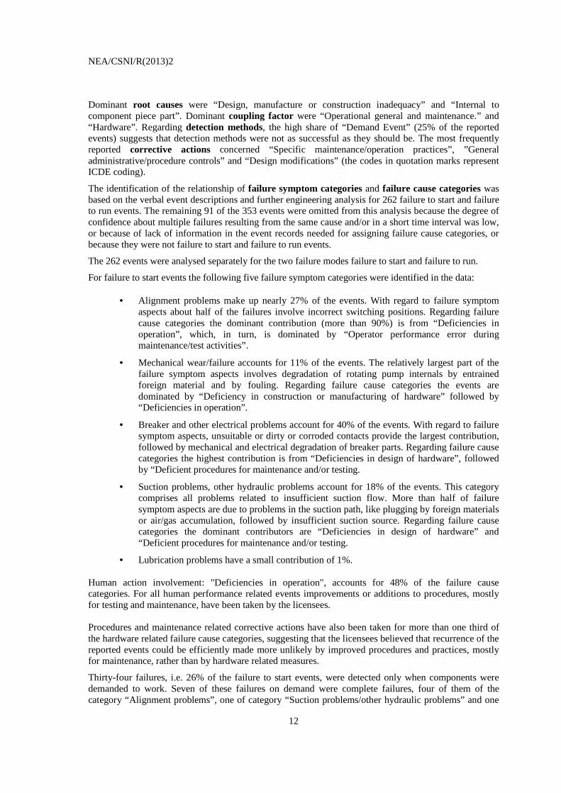
The identification of the relationship of failure symptom categories and failure cause categories was based on the verbal event descriptions and further engineering analysis for 262 failure to start and failure to run events. The remaining 91 of the 353 events were omitted from this analysis because the degree of confidence about multiple failures resulting from the same cause and/or in a short time interval was low, or because of lack of information in the event records needed for assigning failure cause categories, or because they were not failure to start and failure to run events.
The 262 events were analysed separately for the two failure modes failure to start and failure to run.
For failure to start events the following five failure symptom categories were identified in the data:
• Alignment problems make up nearly 27% of the events. With regard to failure symptom aspects about half of the failures involve incorrect switching positions. Regarding failure cause categories the dominant contribution (more than 90%) is from “Deficiencies in operation”, which, in turn, is dominated by “Operator performance error during maintenance/test activities”.
• Mechanical wear/failure accounts for 11% of the events. The relatively largest part of the failure symptom aspects involves degradation of rotating pump internals by entrained foreign material and by fouling. Regarding failure cause categories the events are dominated by “Deficiency in construction or manufacturing of hardware” followed by “Deficiencies in operation”.
• Breaker and other electrical problems account for 40% of the events. With regard to failure symptom aspects, unsuitable or dirty or corroded contacts provide the largest contribution, followed by mechanical and electrical degradation of breaker parts. Regarding failure cause categories the highest contribution is from “Deficiencies in design of hardware”, followed by “Deficient procedures for maintenance and/or testing.
• Suction problems, other hydraulic problems account for 18% of the events. This category comprises all problems related to insufficient suction flow. More than half of failure symptom aspects are due to problems in the suction path, like plugging by foreign materials or air/gas accumulation, followed by insufficient suction source. Regarding failure cause categories the dominant contributors are “Deficiencies in design of hardware” and “Deficient procedures for maintenance and/or testing.
• Lubrication problems have a small contribution of 1%. Human action involvement: "Deficiencies in operation", accounts for 48% of the failure cause categories. For all human performance related events improvements or additions to procedures, mostly for testing and maintenance, have been taken by the licensees. Procedures and maintenance related corrective actions have also been taken for more than one third of the hardware related failure cause categories, suggesting that the licensees believed that recurrence of the reported events could be efficiently made more unlikely by improved procedures and practices, mostly for maintenance, rather than by hardware related measures.
Thirty-four failures, i.e. 26% of the failure to start events, were detected only when components were demanded to work. Seven of these failures on demand were complete failures, four of them of the category “Alignment problems”, one of category “Suction problems/other hydraulic problems” and one

NEA/CSNI/R(2013)2
13
of category “Breaker and other electrical problems”. Four of them were caused by “Operator performance error during maintenance/test activities”. This indicates that testing practices/techniques have not always been capable of detecting human error induced deficiencies.
For failure to run events the following four failure symptom categories were identified as dominant in the data:
• Mechanical wear/failure is the dominant contribution, accounting for 28% of the events.
The largest part of the failure symptom aspects involves degradation of pumps or pump motors by vibrations, and of rotating pump internals by entrained foreign material. “Deficiency in construction or manufacturing of hardware” is the dominant failure cause category.
• Breaker and other electrical problems account for 22% of the events. Connectors that are insufficiently protected against moisture provide the largest contribution to failure symptom aspects, followed by mechanical or electrical degradation of breaker parts. Deficient procedures for maintenance and/or testing“, followed by “Deficiencies in design of hardware” are the dominant failure cause categories.
• Lubrication problems account 23% of the events. Insufficient quantity of lubricants, insufficient quality of lubricants and foreign material in lubrication oil provide the largest contributions to failure symptom aspects. “Deficient procedures for maintenance and/or testing“, followed by “Deficiencies in design of hardware (in this case wrong specification of lubricants)” are the dominant failure cause categories.
• Suction problems and other hydraulic problems account for 18% of the events. More than half of the failure symptom aspects s are due to problems in the suction path, like plugging by foreign materials or air/gas accumulation, followed by insufficient suction source. “Deficiencies in design of hardware” and “Deficient procedures for maintenance and/or testing” are the dominant failure cause categories.
Deficiencies in operation contribute 50% of the failure cause categories, the majority due to "Deficient maintenance procedures/practices", followed by “Operator performance error during maintenance/test activities”. In many cases, test and maintenance intervals were too long to detect the failures before multiple components were affected.
The other 50% of failure causes categories are design, construction, manufacturing deficiencies, mainly due to "Deficiencies in design of hardware" and “Deficiencies in construction/ manufacturing of hardware” and. The failures are mostly caused by mechanical wear, suction or other hydraulic problems and lubrication problems.
Fifty-one failures, i.e. about 24% of the failure to run events, were detected only when the component was “demanded to work”, i.e. the pumps started successfully but failed during operation. Ten of these failures on demand were complete failures, mostly of the failure symptom category “Suction problems/other hydraulic problems”. They are equally caused by operational problems and hardware problems. This indicates that maintenance and test procedures as well as testing practices have not always been capable of detecting the evolving failures.
For the 262 events analysed in detail, procedures and maintenance related corrective actions have been taken by the utilities in response to 62% of the events, although “Deficiencies in operation” were involved in only 52% of the events. This suggests that the operators thought that improved procedures and maintenance rules would be an effective and efficient defense, even against hardware related failures.
NEA/CSNI/R(2013)2
14
The high share of the procedure and maintenance related corrective actions underlines the paramount importance of continued reviews and improvements of existing maintenance and operating procedures and practices in order to enhance the plant-specific CCF defense. Significant differences exist in the involvement of human errors in complete CCFs between failure to start events and failure to run events:
• for failure to start, 85% of the complete CCFs involve human errors, only 14% are hardware related
− the share of human errors in complete CCFs (85%) is significantly higher than the share of human errors of 48% in general failure to start events
− for failure to start events there is a relatively high conditional probability of 0.19, given a failure to start event, that complete failures occur due to human error.
• for the failure to run events analysed in detail, 50% of the complete CCFs involve human
errors, 50% are hardware related
− the share of complete CCFs caused by design, construction, manufacturing deficiencies (50%) is equal to the share of these events (50%) in general failure to run events.
− For failure to run events the conditional probability of a complete failure to be caused by human error, given a failure to run event, is 0.06.
This suggests that maintenance and test activities are significantly more effective for preventing complete failures in failure to run events than in failure to start events. Thus, maintenance and test activities should specifically focus on the prevention of failure to start events.

NEA/CSNI/R(2013)2
15
ACRONYMS
AC Alternating Current
BWR Boiling Water Reactor
CP Centrifugal Pump
CCF Common Cause Failure
CNSC Canadian Nuclear Safety Commission (Canada)
CSN Consejo de Seguridad Nuclear (Spain)
CSNI Committee on the Safety of Nuclear Installations
DC Direct Current (Continuous current)
ENSI Swiss Federal Nuclear Safety Inspectorate (Switzerland)
FC Failure to Close
FO Failure to Open
GRS Gesellschaft für Anlagen- und Reaktorsicherheit (Germany)
I&C Instrumentation and Control
ICDE International Common Cause Failure Data Exchange
IRS Incident Reporting System
IRSN Institut de Radioprotection et de Sûreté Nucléaire (France)
JNES Japan Nuclear Energy Organisation (Japan)
KAERI Korea Atomic Energy Research Institute (Republic of Korea)
LOCA Loss-of-Coolant Accident
LOSP Loss of Offsite Power
NEA Nuclear Energy Agency
NPP Nuclear Power Plant
NRC Nuclear Regulatory Commission (USA)
OA Operating Agent
OECD Organisation for Economic Co-operation and Development
ONR Office for Nuclear Regulation (UK)
OP Observed Population
PRA Probabilistic Risk Assessment
PSA Probabilistic Safety Assessment

NEA/CSNI/R(2013)2
16
PWR Pressurized Water Reactor
RPS Reactor Protection System
SSM Swedish Radiation Safety Authority (Sweden)
STUK Finnish Centre for Radiation and Nuclear Safety (Finland)
UV Under voltage

NEA/CSNI/R(2013)2
17
GLOSSARY
(Ref. 2 to 5)
Common Cause Event: A dependent failure in which two or more component fault states exist simultaneously, or within a short time interval, and are a direct result of a shared cause. Complete failure: The component has completely failed and will not perform its function. For example, if the cause prevented a pump from starting, the pump has completely failed and impairment would be complete. If the description is vague this code is assigned in order to be conservative. Component: An element of plant hardware designed to provide a particular function. Component Boundary: The component boundary encompasses the set of piece parts that are considered to form the component. Coupling Factor/Mechanism: The coupling factor field describes the mechanism that ties multiple impairments together and identifies the influences that created the conditions for multiple components to be affected. Defence: Any operational, maintenance, and design measures taken to diminish the probability and/or consequences of common-cause failures. Exposed Population (EP): A set of similar or identical components actually having been exposed to the specific common causal mechanism in an actually observed CCF event. Failure: The component is not capable of performing its specified operation according to a success criterion. Failure Cause Categories: A list of potential deficiencies in operation and in design, construction and manufacturing which rendered possible a CCF event to occur. Failure Mechanism: The history describing the events and influences leading to a given failure. Failure Mode: The failure mode describes the function the components failed to perform.

NEA/CSNI/R(2013)2
18
Failure Symptom: An observed deviation from the normal condition or state of a component, indicating degradation or loss of the ability to perform its mission. Failure Symptom Categories: Are component-type-specific groupings of similar failure symptom aspects. Failure Symptom Aspects: Are component-type-specific observed faults or deviant conditions which have led to the CCF event. They are derived from the event description. Degraded: The component is capable of performing the major portion of the safety function, but parts of it are degraded. For example, high bearing temperatures on a pump will not completely disable a pump, but it increases the potential for failing within the duration of its mission. ICDE Event: Impairment 1) of two or more components (with respect to performing a specific function) that exists over a relevant time interval 2) and is the direct result of a shared cause. Incipient: The component is capable of performing the safety function, but parts of it are in a state that -if not corrected - would lead to a degraded state. For example, a pump-packing leak, that does not prevent the pump from performing its function, but could develop to a significant leak. Observed Population (OP): A set of similar or identical components that are considered to have a potential for failure due to a common cause. A specific OP contains a fixed number of components. Sets of similar OPs form the statistical basis for calculating common cause failure rates or probabilities. Root Cause: The most basic reason for a component failure, which, if corrected, could prevent recurrence. The identified root cause may vary depending on the particular defensive strategy adopted against the failure mechanism. Shared-Cause Factor: The shared cause factor allows the analyst to express his degree of confidence about the multiple impairments resulting from the same cause. Timing Factor: This is a measure of the “simultaneity” of multiple impairments. This can be viewed as an indication of the strength-of-coupling in synchronizing failure times.

NEA/CSNI/R(2013)2
19
1 INTRODUCTION
This report presents an overview of the exchange of common cause failure (CCF) data of centrifugal pumps (CP) among several countries. The objectives of this report are:
• To describe the data profile in the ICDE database for CP and to develop qualitative insights in the nature of the reported events, expressed by root causes, coupling factors, and corrective actions; and
• To develop the failure mechanisms and phenomena involved in the events, their relationship
to the root causes, and possibilities for improvement. The ICDE Project was organized to exchange CCF data among countries. A brief description of the project, its objectives, and the participating countries, is given in Section 2. Section 3 presents the definition of common cause failure and the ICDE event definitions. Section 4 presents a description of the CP, and Section 5 summarizes the coding guidelines for this component. Sections 6 and 7 contain the results of the study. Section 8 contains the summary and conclusions of the study.

NEA/CSNI/R(2013)2
20

NEA/CSNI/R(2013)2
21
2 ICDE PROJECT
2.1 Background
Common-cause-failure (CCF) events can significantly impact the availability of safety systems of nuclear power plants. In recognition of this, CCF data are systematically being collected and analysed in several countries. A serious obstacle to the use of national qualitative and quantitative data collections by other countries is that the criteria and interpretations applied in the collection and analysis of events and data differ among the various countries. A further impediment is that descriptions of reported events and their root causes and coupling factors, which are important to the assessment of the events, are usually written in the native language of the countries where the events were observed.
To overcome these obstacles, the preparation for the international common-cause data exchange (ICDE) project was initiated in August of 1994. Since April 1998, the OECD/NEA has formally operated the project. The Phase II had an agreement period covered years 2000-2002, phase III covered the period 2002-2005, phase IV 2005-2008 and phase V 2008 -2011. Member countries under the Phase IV Agreement of OECD/NEA and the organisations representing them in the project are: Canada (CNSC), Finland (STUK), France (IRSN), Germany (GRS), Japan (JAPEIC), Korea (KAERI), Spain (CSN), Sweden (SSM), Switzerland (ENSI), United Kingdom (NII), and United States (NRC). Phase VI is planned to begin in April 2011
2.2 Objectives of the ICDE Project
The objective of the ICDE activity is to provide a framework for a multinational co-operation:
a) collect and analyse Common-Cause Failure (CCF) events over the long term so as to better understand such events, their causes, and their prevention;
b) generate qualitative insights into the root causes of CCF events which can then be used to derive approaches or mechanisms for their prevention or for mitigating their consequences;
c) establish a mechanism for the efficient feedback of experience gained in connection with CCF phenomena, including the development of defences against their occurrence, such as indicators for risk based inspections;
d) generate quantitative insights and record event attributes to facilitate quantification of CCF frequencies in member countries; and
e) use the ICDE data to estimate CCF parameters.
2.3 Scope of the ICDE Project
The ICDE Project aims to include all possible events of interest, comprising complete, partial, and incipient CCF events, called “ICDE events” in this report. The project covers the key components of the main safety systems, including centrifugal pumps, diesel generators, motor operated valves, power
NEA/CSNI/R(2013)2
22
operated relief valves, safety relief valves, check valves, batteries, control rod drive mechanisms (CRDA), circuit breakers, level measurement, heat exchangers, etc.
2.4 Reporting and Documentation
The ICDE project has produced the following reports, which can be accessed through the OECD/NEA CSNI web site for CSNI reports [1]:
• Collection and analysis of common-cause failure of centrifugal pumps [NEA/CSNI/R(99)2]. Issued September 1999.
• Collection and analysis of common-cause failure of emergency diesel generators [NEA/CSNI/R(2000)20]. Issued May 2000.
• Collection and analysis of common-cause failure of motor-operated valves [NEA/CSNI/R(2001)10]. Issued February 2001.
• Collection and analysis of common-cause failure of safety valves and relief valves [NEA/CSNI/R(2002)19]. Issued October 2002.
• Collection and analysis of common-cause failure of check valves [NEA/CSNI/R(2003)15]. Issued February 2003.
• Collection and analysis of common-cause failure of batteries [NEA/CSNI/R(2003)19]. Issued September 2003.
• Collection and analysis of level measurement components [NEA/CSNI/R(2008)8]. Issued March 2008.
• Collection and analysis of common-cause failure of switching devices and circuit breakers [NEA/CSNI/R(2008)1]. Issued October 2007.
• ICDE General Coding Guidelines [NEA/CSNI/R(2004)4]. Issued January 2004.
• Proceedings of ICDE Workshop on the qualitative and quantitative use of ICDE Data [NEA/CSNI/R(2001)8. Issued November 2002.
2.5 Database Management
Data are collected in an MS.NET based database implemented and maintained at ES-Konsult, Sweden, the appointed ICDE Operating Agent. The database is regularly updated. It is operated by the Operating Agent following the decisions of the ICDE Steering Group.
2.6 ICDE Coding Format and Coding Guidelines
Data collection guidelines have been developed during the project and are continually revised. They describe the methods and documentation requirements necessary for the development of the ICDE databases and reports. The format for data collection is described in the general coding guideline and in the component specific guidelines. Component specific guidelines are developed for all analysed component types as the ICDE plans evolve [2].
2.7 Protection of Proprietary Rights
Procedures for protecting confidential information have been developed and are documented in the Terms and Conditions of the ICDE project [4]. The co-ordinators in the participating countries are responsible for maintaining proprietary rights according to the stipulations in the ICDE Terms and Conditions [4]. The data collected in the database are password protected and are only available to ICDE participants who have provided data.
NEA/CSNI/R(2013)2
23
3 DEFINITION OF COMMON-CAUSE EVENTS AND ICDE EVENTS
In the modelling of common-cause failures in systems consisting of several redundant components, two kinds of events are identified:
• Unavailability of a specific set of components of the system, due to a common dependency, for example on a support function. If such dependencies are known, they can be explicitly modelled in a PSA.
• Unavailability of a specific set of components of the system due to shared causes that are
not explicitly represented in the system logic model. Such events are also called "residual" CCFs, and are incorporated in PSA analyses by parametric models.
There is no rigid borderline between the two types of CCF events. There are examples in the PSA literature of CCF events that are explicitly modelled in one PSA and are treated as residual CCF in other PSAs (for example, CCF of auxiliary feed-water pumps due to steam binding, resulting from leaking check valves).
Several definitions of CCF events can be found in the literature, for example, “Common Cause Failure Data Collection and Analysis System, Vol. 1, NUREG/CR-6268”: [3]
• Common-Cause Event: A dependent failure in which two or more component fault states exist simultaneously, or within a short time interval, and are a direct result of a shared cause.
The data collection in the ICDE project comprises complete as well as potential CCF. To include all events of interest, an ‘ICDE event’ is defined as follows:
• ICDE Event: Impairment1 of two or more components (with respect to performing a specific function) that exists over a relevant time interval2 and is the direct result of a shared cause.
The ICDE data analysts may add interesting events that fall outside the ICDE event definition but are examples of recurrent - eventually non random - failures.
1 Possible attributes of impairment are the following:
• Complete failure of the component to perform its function • Degraded ability of the component to perform its function • Incipient failure of the component • Default is component is working according to specifications. 2 Relevant time interval: two pertinent inspection periods (for the particular impairment) or if unknown, a scheduled outage period.

NEA/CSNI/R(2013)2
24

NEA/CSNI/R(2013)2
25
4 COMPONENT DESCRIPTION
The coding guidelines for centrifugal pumps [2] is applied in the following description.
4.1 General Description of the Component Centrifugal Pumps
The family of pumps is comprised of those centrifugal pumps (CP) that are motor driven and are used for the purpose of establishing flow to or from the primary system or support systems. Centrifugal pump data are being collected for the systems (the corresponding IRS system coding is added in parentheses):
• auxiliary/emergency feedwater (3.BB)
• high pressure safety injection, PWR (3.BG)
• low pressure safety injection (may include residual heat removal), PWR (3.BG)
• gas circulators GCR (3.BG)
• residual heat removal (if out of emergency core cooling function), PWR and BWR (3.BE)
• containment spray (3.DD)
• ice condenser (3.DD)
• high pressure coolant injection/reactor core isolation cooling, BWR (3.BA)
• low pressure coolant injection (may include residual heat removal), BWR (3.BG)
• component cooling, including reactor building closed cooling water (3.CA)
• pressure vessel cooling and reactor ancillaries cooling GCR (3.CA)
• essential SWS (3.CB)
• essential raw cooling water (3.CB)
• standby liquid control, BWR (3.BD)
• LP and HP main and standby boiler circulating water pumps GCR (3.DG)
• emergency power generation and auxiliaries, including supply of fuel and lubrication oil (3.EF)
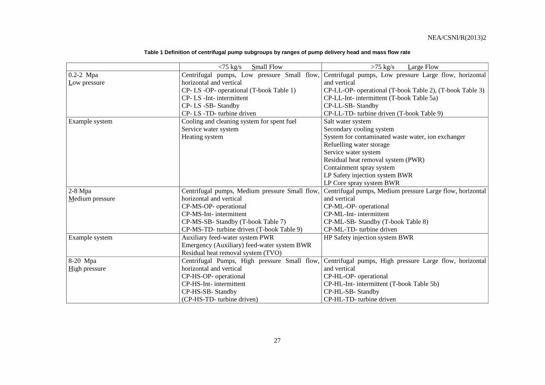
For data evaluation purposes, the family of centrifugal pumps is subdivided into six subgroups characterized by pump delivery head and mass flow rate. The classification is shown in Table 1.
4.2 Component Boundaries
The component for this study is the centrifugal pump, comprised of a pump with its internal piece-part components and a driver. The driver includes the circuit breaker, power leads, local protective devices, open/close limit switches, torque switches, and the motor. The control circuit that induces a start and

NEA/CSNI/R(2013)2
26
stop signal to a CP is not included within the CP boundary if it also controls other component functions, such as other pump actions, opening or closing of valves, etc.
4.3 Event Boundary
The mission for a CP is to maintain the water inventory in the primary system, or to maintain cooling flow in the primary or secondary system or in support systems. Some of the systems for which CP data are being collected serve dual purposes (low pressure injection and residual heat removal), such that the flow paths are also used during normal plant operation. Failure of the CP to perform its mission occurs if a pump that is required to be running to allow injection or cooling flow fails to start or fails to run.
4.4 Basic unit for ICDE event collection
The basic set for centrifugal pump data collection is the observed population (OP). The OP size typically varies from two to twelve, with the bulk in the two to four range.
4.5 Time frame for ICDE event exchange
The minimum period of exchange should cover a period of 5 years (The initial pump exchange covered Jan. 1 1990 - Dec. 31 1994, ref. Park City protocol).
NEA/CSNI/R(2013)2
27
Table 1 Definition of centrifugal pump subgroups by ranges of pump delivery head and mass flow rate
<75 kg/s Small Flow >75 kg/s Large Flow 0.2-2 Mpa Low pressure
Centrifugal pumps, Low pressure Small flow, horizontal and vertical CP- LS -OP- operational (T-book Table 1) CP- LS -Int- intermittent CP- LS -SB- Standby CP- LS -TD- turbine driven
Centrifugal pumps, Low pressure Large flow, horizontal and vertical CP-LL-OP- operational (T-book Table 2), (T-book Table 3) CP-LL-Int- intermittent (T-book Table 5a) CP-LL-SB- Standby CP-LL-TD- turbine driven (T-book Table 9)
Example system Cooling and cleaning system for spent fuel Service water system Heating system
Salt water system Secondary cooling system System for contaminated waste water, ion exchanger Refuelling water storage Service water system Residual heat removal system (PWR) Containment spray system LP Safety injection system BWR LP Core spray system BWR
2-8 Mpa Medium pressure
Centrifugal pumps, Medium pressure Small flow, horizontal and vertical CP-MS-OP- operational CP-MS-Int- intermittent CP-MS-SB- Standby (T-book Table 7) CP-MS-TD- turbine driven (T-book Table 9)
Centrifugal pumps, Medium pressure Large flow, horizontal and vertical CP-ML-OP- operational CP-ML-Int- intermittent CP-ML-SB- Standby (T-book Table 8) CP-ML-TD- turbine driven
Example system Auxiliary feed-water system PWR Emergency (Auxiliary) feed-water system BWR Residual heat removal system (TVO)
HP Safety injection system BWR
8-20 Mpa High pressure
Centrifugal Pumps, High pressure Small flow, horizontal and vertical CP-HS-OP- operational CP-HS-Int- intermittent CP-HS-SB- Standby (CP-HS-TD- turbine driven)
Centrifugal pumps, High pressure Large flow, horizontal and vertical CP-HL-OP- operational CP-HL-Int- intermittent (T-book Table 5b) CP-HL-SB- Standby CP-HL-TD- turbine driven

NEA/CSNI/R(2013)2
28
Figure 1 Physical boundary of centrifugal pumps
NEA/CSNI/R(2013)2
29
5 PUMP EVENT COLLECTION AND CODING GUIDELINES
5.1 Coding Rules and Exceptions
1. In general, the definition of the ICDE event is given in Section 2 of the General ICDE Coding Guidelines [2].
2. Some reports may discuss only one actual failure, and do not consider that the same cause will affect other Pumps, but the licensee replaces the failed component on all pumps as a precautionary measure. This event will be coded as incipient impairment of the components that did not actually fail.
3. In-operability due to seismic or electrical separation violations will not be included, unless an actual failure has occurred.
5.2 Functional Failure Modes
The functional pump failure modes are [5]:
Compulsory failure modes:
1. Failure to Start (FS): failure before nominal operating conditions are reached
2. Failure to Run (FR) failure after nominal operating conditions have been reached
Additional failure modes:
3. Failure to Stop (FC)
4. External leakage (EL)

NEA/CSNI/R(2013)2
30

NEA/CSNI/R(2013)2
31
6 OVERVIEW OF DATABASE CONTENT
CCF data have been collected for Centrifugal Pumps (CP). Organisations from Canada, Finland, France, Germany, Japan, Spain, Sweden, United Kingdom, and United States have contributed to this data exchange. Three-hundred-fifty-three (353) ICDE events were reported from nuclear power plants (pressurized water reactors, boiling water reactors, Magnox and advanced gas reactors). The data span a period from 1975 through 2009. The data are not necessarily complete for each country throughout this period.
Collecting these events has included both top-down work by identifying events on basis of licensee event reports and bottom-up work by going through events in plant maintenance databases. Although most CCF events are identified through the former mechanism, the latter has led to ICDE events that were not identified otherwise. This bottom-up work is rather resource intensive. The distributions of events in the following section are strictly based on the classes given in the ICDE coding guidelines [2]. In Section 7, a deeper engineering analysis of the events is presented.
6.1 Failure Mode and Impact of Failure
For each event in the ICDE database, the impairment of each component in the OP has been defined according to the categorisation of the general coding guidelines [2], with interpretation as presented in the Centrifugal Pumps coding guidelines (see Section 5.3) and summarised here.
• C denotes complete failure. The component has completely failed and will not perform its function. For example, if the cause prevents a pump from starting, the pump has completely failed and impairment would be complete. If the description is vague this code is assigned in order to be conservative.
• D denotes degraded. The component is capable of performing the major portion of the
safety function, but parts of it are degraded. For example, reduced capacity of a pump.
• I denotes incipient. The component is capable of performing the safety function, but parts of
it are in a state that - if not corrected - would lead to a degraded state. This coding is selected when slight damage is evident. If parts were replaced on some components due to failures of parallel components, this code is used for the components that didn’t actually experience a failure. This also applies if it was decided to implement said replacement at a later time.
• W denotes working, i.e. component has suffered no damage. The component is working according to specifications.
Table 2 summarizes the reported ICDE events by failure mode and impact of failure. 353 ICDE events have been collected in the ICDE database. 42 of them were complete CCF events. Complete CCF events are ICDE events in which all components of the exposed population (or observed population

NEA/CSNI/R(2013)2
32
respectively) fail completely due to the same cause and within a short time interval. A further subclass of ICDE events are partial CCF events having at least two components, but not all of them, completely failed.
Table 2 Failure mode distribution
FAILURE MODE
No. of ICDE events
Impact of failure
Complete CCF
events 1)
Partial CCF events
2)
FS – Failure to start 131 20 20 FR – Failure to run 211 20 16 FC – Failure to stop 5 1 1 EL – External leakage 6 1 - TOTAL 353 42 37
1 Only events with time factor or shared cause factor “high” are included. 2 Events with time factor or shared cause factor “low” are excluded The most common failure mode was "failure to run” (60%), followed by “failure to start” (37%). Complete CCF makes up 12% of the pump events.
6.2 Observed Population Size and Exposed Population
Not relevant for centrifugal pumps. There are only 17 events (5%) where there is a difference between OP size and exposed population.
6.3 Root Cause, Coupling Factor, Corrective Action and Detection Method
6.3.1 Root Cause
The general coding guidelines [2] define root cause as follows. The cause field identifies the most basic reason for the component’s failure. Most failure reports address an immediate cause and an underlying cause. For this project, the appropriate code is the one representing the common cause, or if all levels of causes are common cause, the most readily identifiable cause. The following coding is suggested:
• C – State of other component(s) (if not modelled in PSA). The cause of the state of the component under consideration is due to state of another component. Examples are loss of power and loss of cooling.
• D – Design, manufacture or construction inadequacy. This category encompasses actions
and decisions taken during design, manufacture, or installation of components, both before and after the plant is operational. Included in the design process are the equipment and system specification, material specification, and initial construction that would not be considered a maintenance function. This category also includes design modifications.
• A – Abnormal environmental stress. Represents causes related to a harsh environment that
is not within component design specifications. Specific mechanisms include chemical reactions, electromagnetic interference, fire/smoke, impact loads, moisture (sprays, floods,

NEA/CSNI/R(2013)2
33
etc.) radiation, abnormally high or low temperature, vibration load, and severe natural events.
• H – Human actions. Represents causes related to errors of omission or commission on the
part of plant staff or contractor staff. An example is a failure to follow the correct procedure. This category includes accidental actions, and failure to follow procedures for construction, modification, operation, maintenance, calibration, and testing. This category also includes deficient training.
• M – Maintenance. All maintenance not captured by H - human actions or P - procedure
inadequacy. • I – Internal to component, piece part. Deals with malfunctioning of parts internal to the
component. Internal causes result from phenomena such as normal wear or other intrinsic failure mechanisms. It includes the influence of the environment of the component. Specific mechanisms include erosion/corrosion, internal contamination, fatigue, and wear out/end of life.
• P – Procedure inadequacy. Refers to ambiguity, incompleteness, or error in procedures for
operation and maintenance of equipment. This includes inadequacy in construction, modification, administrative, operational, maintenance, test and calibration procedures. This can also include the administrative control of procedures, such as change control.
• O – Other. The cause of events is known, but does not fit in one of the other categories. • U – Unknown. This cause category is used when the cause of the component state cannot be
identified. Figure 1 summarises the root causes of the analysed events as coded in the ICDE database.
Figure 2 Root cause distribution (without “Others”)

NEA/CSNI/R(2013)2
34
The dominant root causes based on ICDE codes are “Design, manufacture or construction inadequacy” accounting for 26% of the events, followed by “Internal to component, piece part” accounting for 20% of the events.
6.3.2 Coupling Factor
The general coding guidelines [2] define coupling factor as follows. The coupling factor field describes the mechanism that ties multiple impairments together and identifies the influences that created the conditions for multiple components to be affected. For some events, the root cause and the coupling factor are broadly similar, with the combination of coding serving to give more detail as to the causal mechanisms. Selection is made from the following codes:
• H – Hardware (component, system configuration, manufacturing quality, installation configuration quality). Coded if none of or more than one of HC, HS or HQ applies, or if there is not enough information to identify the specific “hardware” coupling factor.
• HC – Hardware design. Components share the same design and internal parts.
• HS – System design. The CCF event is the result of design features within the system in
which the components are located.
• HQ – Hardware quality deficiency. Components share hardware quality deficiencies from the manufacturing process. Components share installation or construction features, from initial installation, construction, or subsequent modifications.
• O – Operational (maintenance/test (M/T) schedule, M/T procedures, M/T staff, operation
procedure, operation staff). Coded if none of or more than one of OMS, OMP, OMF, OP or OF applies, or if there is not enough information to identify the specific “maintenance or operation” coupling factor.
• OMS – Maintenance/test (M/T) schedule. Components share maintenance and test
schedules. For example, the component failed because maintenance was delayed until failure.
• OMP – M/T procedure. Components are affected by the same inadequate maintenance or
test procedure. For example, the component failed because the maintenance procedure was incorrect or a calibration set point was incorrectly specified.
• OMF – M/T staff. Components are affected by a maintenance staff error.
• OP – Operation procedure. Components are affected by an inadequate operations
procedure.
• OF – Operation staff. Components are affected by the same operations staff personnel error.
• EI – Environmental internal. Components share the same internal environment. For example, the process fluid flowing through the component was too hot.
• EE – Environmental external. Components share the same external environment. For
example, the room that contains the components was too hot.
NEA/CSNI/R(2013)2
35
• U – Unknown. Sufficient information was not available in the event report to determine a definitive coupling factor.
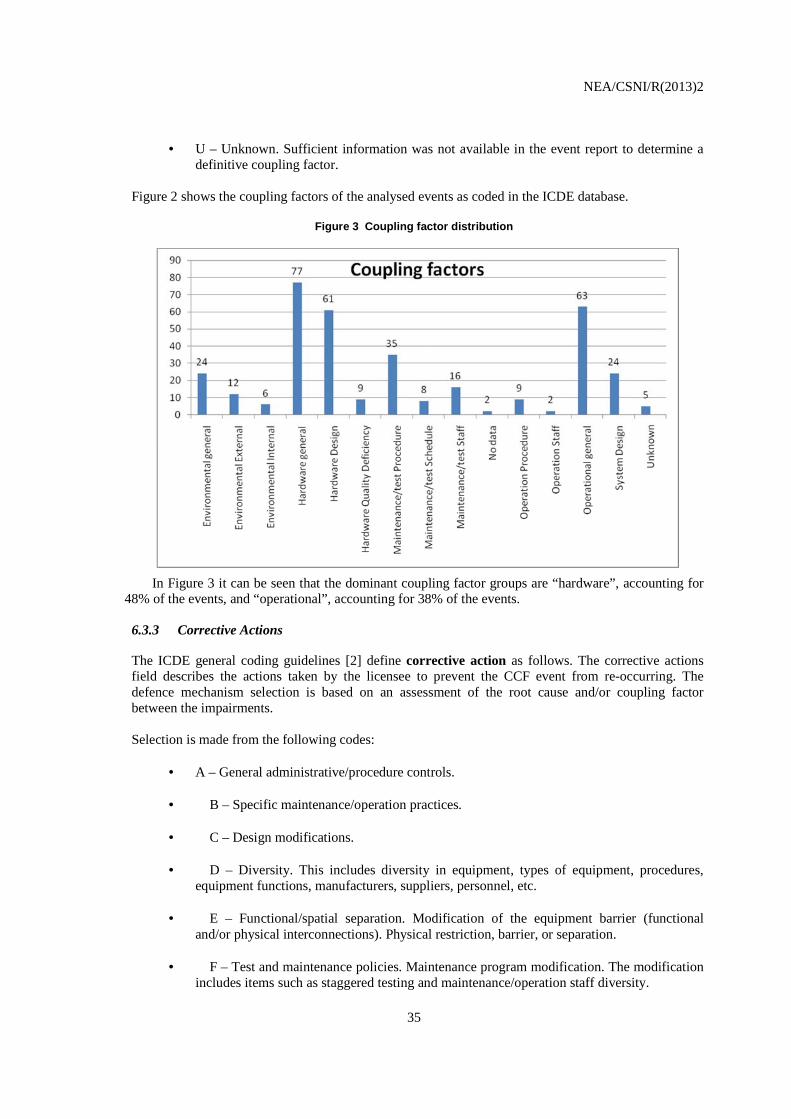
Figure 2 shows the coupling factors of the analysed events as coded in the ICDE database.
Figure 3 Coupling factor distribution
In Figure 3 it can be seen that the dominant coupling factor groups are “hardware”, accounting for 48% of the events, and “operational”, accounting for 38% of the events.
6.3.3 Corrective Actions
The ICDE general coding guidelines [2] define corrective action as follows. The corrective actions field describes the actions taken by the licensee to prevent the CCF event from re-occurring. The defence mechanism selection is based on an assessment of the root cause and/or coupling factor between the impairments. Selection is made from the following codes:
• A – General administrative/procedure controls.
• B – Specific maintenance/operation practices.
• C – Design modifications.
• D – Diversity. This includes diversity in equipment, types of equipment, procedures, equipment functions, manufacturers, suppliers, personnel, etc.
• E – Functional/spatial separation. Modification of the equipment barrier (functional
and/or physical interconnections). Physical restriction, barrier, or separation.
• F – Test and maintenance policies. Maintenance program modification. The modification includes items such as staggered testing and maintenance/operation staff diversity.

NEA/CSNI/R(2013)2
36
• G – Fixing of component.
• O – Other. The corrective action is not included in the classification scheme.
• U – Unknown. Adequate detail is not provided to make adequate corrective action
identification.
Figure 4 summarizes the corrective actions of the analysed events as coded in the ICDE database.
Figure 4 Corrective actions distribution
Improvement of maintenance and test procedures makes up 56% of the corrective actions taken, while actions related to design, construction and manufacturing make up 42% of the corrective actions.
6.3.4 Detection Methods
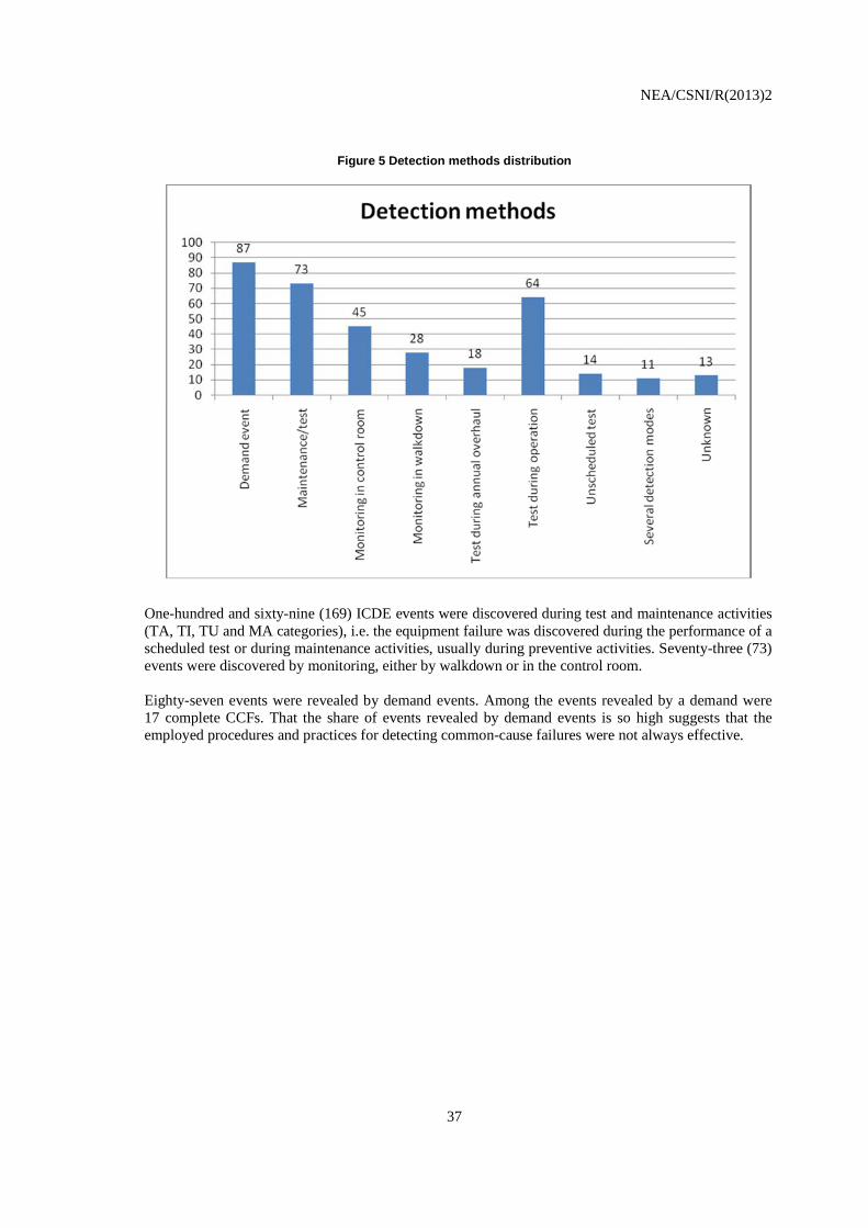
Figure 5 summarises how the failures were detected. In cases of several detection modes in one OP where the detection mode for at least one component was “demand event”, the coding of the event was changed to “demand event” if the event record clearly showed that demand was the first type of detection mode to occur.
NEA/CSNI/R(2013)2
37
Figure 5 Detection methods distribution
One-hundred and sixty-nine (169) ICDE events were discovered during test and maintenance activities (TA, TI, TU and MA categories), i.e. the equipment failure was discovered during the performance of a scheduled test or during maintenance activities, usually during preventive activities. Seventy-three (73) events were discovered by monitoring, either by walkdown or in the control room. Eighty-seven events were revealed by demand events. Among the events revealed by a demand were 17 complete CCFs. That the share of events revealed by demand events is so high suggests that the employed procedures and practices for detecting common-cause failures were not always effective.

NEA/CSNI/R(2013)2
38
NEA/CSNI/R(2013)2
39
7 ENGINEERING ASPECTS OF THE COLLECTED EVENTS
7.1 Scope
The intention of this section is to provide the reader with a deeper qualitative insight in the database content beyond that obtained from using the database coding only (as performed in Section 6 of this report). In the subsequent paragraphs a detailed analysis of failure symptoms and failure causes is presented for failure to start and failure to run events. For that purpose, all events classified with a low time factor, or a low shared cause factor were omitted because the degree of confidence about multiple failures resulting from the same cause and/or in a short time interval is low in such cases. Furthermore, 35 events with incomplete event coding where also omitted because the assignment to a failure cause category was not possible, see the explanation given in section 7.2. As a result of this screening process, 262 of the 353 reported ICDE events were reviewed in more detail with respect to failure causes, failure symptom categories and failure symptom aspects. In a second step, the review was focused on complete CCF events.
7.2 Assessment Basis
In the following sections, the 262 selected events, as defined above, are analysed with respect to failure symptoms and failure causes. The following definitions are applied: Failure Symptom is an observed deviation from the normal condition or state of a component, indicating degradation or loss of the ability to perform its mission. Failure Symptom Aspects are component-type specific observed faults or deviant conditions which have led to the CCF event. They are derived from the event descriptions. Failure Symptom Categories are component-type-specific groupings of similar failure symptom aspects. Failure Cause Categories are a list of potential deficiencies in operation and in design, construction and manufacturing which rendered possible a CCF event to occur. Appropriate failure symptom categories and failure symptom aspects are first identified by engineering binning derived from the verbal event descriptions. For the identification of the failure cause categories, root causes are combined with coupling factors, because, by definition, it is the coupling factor that identifies the mechanism that ties together multiple failures and the influences that created the conditions for multiple components to be affected. The root cause alone does not provide the information required for identifying failure cause categories. In the assessment matrices only events are included which permit assignment to "failure cause categories". For 35 events (after subtraction of those with time factor and/or coupling factor L) the root cause is coded “Unknown” and the coupling factor is not human error related. In this situation the assignment to a “failure cause category” is not possible, see the definition of “failure cause categories” in section 7.4.

NEA/CSNI/R(2013)2
40
Finally, the mapping of failure symptom categories onto failure cause categories is shown by the assessment matrices "Relationship of Failure Symptoms and Failure Cause Categories for Failure to Start", Table 3, and "Relationship of Failure Symptoms and Failure Cause Categories for Failure to Run", Table 5. These matrices provide the basis for deriving insights and conclusions.
7.3 Failure Symptom Categories
Failure symptom categories are derived from the event descriptions. The following failure symptom categories were identified as being important to the analysis:
• Alignment problems
• Mechanical wear/failure
• Lubrication problems
• Breaker problems and other electrical problems
• Suction problems/other hydraulic problems
• Others
7.4 Failure Cause Categories
Two principal categories of failure causes are introduced:
Deficiencies in operation
This group comprises all ICDE events that involve human errors, expressed by a human error related root cause, or a human error related coupling factor. Note that, following this definition, events are included in this group if
• The root cause is human error related or
• The root cause is hardware related but human errors have created the conditions for multiple components to be affected by a shared cause, i.e. if the coupling factor is human error related.
• The root cause and coupling factor are human error related. Three failure cause categories have been identified as being important in this group:
• O1 Deficient procedures for maintenance and/or testing
• O2 Insufficient attention to aging of piece parts
• O3 Operator performance error during maintenance/test activities
Deficiencies in design, construction, manufacturing This group comprises all events with hardware related root cause and hardware related coupling factor. Thus, an event is only included, for example, in category D (design deficiency) if the root cause is coded as “design”, combined with any hardware related coupling factor, or if the coupling factor is coded as “hardware design” or “system design”, combined with any hardware related root cause. Three failure cause categories have been identified for this group:
• D Deficiency in design of hardware
NEA/CSNI/R(2013)2
41
• C/M Deficiency in construction or manufacturing of hardware
• D-MOD Deficient design modifications
7.5 Assessment matrices
Failure symptom categories and their relationship to the failure cause categories differ significantly between failure to start and failure to run. Therefore, these two failure modes will be treated separately in this report. The matrices "Relationship of failure symptom categories and failure cause categories for failure to start”, Table 3, and "Relationship of failure symptom categories and failure cause categories for failure to run”, Table 5, form the basis for interpreting the collected data. The failure symptom categories as defined in Section 7.3 are assigned to the columns of the matrices, the failure cause categories as defined in Section 7.4 are assigned to the rows of the matrices. The matrix entries show the number of ICDE events having been reported for each of the failure symptom categories/failure cause categories combinations. Note that these observations are based on the events remaining after deletion from the data set of those with a “low” time factor or shared cause factor and others with incomplete event coding.

NEA/CSNI/R(2013)2
42
Table 3 Relationship of Failure Symptom Categories and Failure Cause Categories for failure to start (without events with time factor L and/or shared cause factor L)
Failure Symptom Categories
Failure Cause Categories
B1
Alignment problems
B2
Mechanical wear/failure
B3
Breaker problems, other
electrical problems
B4
Suction problems, other
hydraulic problems
B5
Lubrication problems
Others
Total
Deficiencies in operation
(root cause or coupling factor are
human error related)
22 3 10 6 1 1 43
O1
Deficient maintenance/test
procedures
7 1 8 4 1 1 22
O2
Insufficient attention to aging of piece
parts
2 2
O3
Operator performance error
during maintenance/test
activities
15 2 2 19
Design, construction,
manufacturing deficiencies
(root cause and coupling factor are hardware related)
2 7 25 10 - 3 47
D
Deficiencies in design of hardware
1 2 19 8 30
C/M
Deficiencies in construction/
manufacturing of hardware
5 5 2 - 1 13
D-MOD
Deficient design modifications
1 2 - 1 4
Total 24 10 36 16 1 3 90
Unknown failure cause category
23

NEA/CSNI/R(2013)2
43
7.5.1 Evaluation for failure to start
The following observations are made from Table 3 and from the failure analysis fields of the database:
7.5.1.1 Failure cause categories for failure to start
Deficiencies in operation contributed 48% of the failure cause categories, with 24% due to "Deficient maintenance procedures/practices" and 22% due to “Operator performance error during maintenance/test activities. In many cases, test and maintenance intervals were too long to detect the failures before multiple components were affected, or too little attention was given to the possibility of operator performance errors.
The other 52% of failure cause categories were design, construction, manufacturing deficiencies, mainly due to "Deficiencies in design of hardware", followed by “Deficiencies in construction/manufacturing of hardware”. Most of these failures were caused by breaker and other electrical problems and by suction or other hydraulic problems.
7.5.1.2 Failure symptom categories and failure symptom aspects for failure to start
B1. Alignment problems make up nearly 27% of the events. With regard to failure symptom aspects about half of the failures involve incorrect switching positions. Regarding failure cause categories the dominant contribution (more than 90%) is from “Deficiencies in operation”, which, in turn, is dominated by “Operator performance error during maintenance/test activities”.
B2. Mechanical wear/failure accounts for 11% of the events. The relatively largest part of the failure
symptom aspects involves degradation of rotating pump internals by entrained foreign material and by fouling. Regarding failure cause categories the events are dominated by “Deficiency in construction or manufacturing of hardware” followed by “Deficiencies in operation”.
B3. Breaker and other electrical problems account for 40% of the events. With regard to failure
symptom aspects, unsuitable or dirty or corroded contacts provide the largest contribution, followed by mechanical and electrical degradation of breaker parts. Regarding failure cause categories the highest contribution is from “Deficiencies in design of hardware”, followed by “Deficient procedures for maintenance and/or testing.
B4. Suction problems, other hydraulic problems account for 18% of the events. This category
comprises all problems related to insufficient suction flow. More than half of failure symptom aspects are due to problems in the suction path, like plugging by foreign materials or air/gas accumulation, followed by insufficient suction source. Regarding failure cause categories the dominant contributors are “Deficiencies in design of hardware” and “Deficient procedures for maintenance and/or testing.
B5. Lubrication problems have a small contribution of 1%. B6. Others. This category comprises various failure symptoms. Its contribution is 3%.
7.5.1.3 Human error involvement for failure to start
• Human action involvement: "Deficiencies in operation", accounts for 48% of the failure cause categories. For all human performance related events improvements or additions to procedures, mostly for testing and maintenance, have been taken by the licensees.
NEA/CSNI/R(2013)2
44
• Procedures and maintenance related corrective actions have also been taken for more than one third of the hardware related failure cause categories, suggesting that the licensees believed that recurrence of the reported events could be efficiently made more unlikely by improved procedures and practices, mostly for maintenance, rather than by hardware related measures.
• In all, for 62% of the events the corrective actions involved modifications of procedures and practices.
Changing practices appears to be a working and low-cost alternative in many cases, even for purely hardware related failures, so the low share of hardware related corrective actions is not surprising.
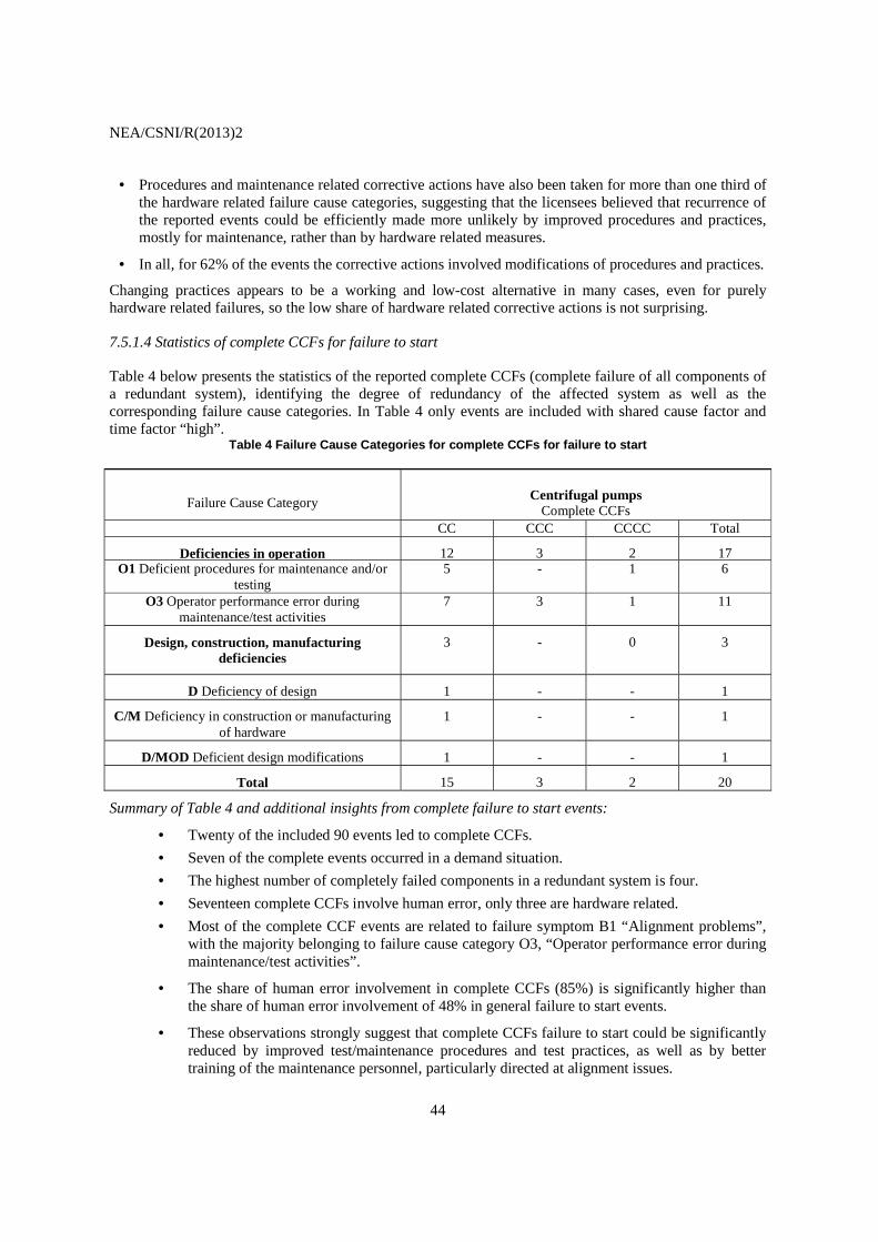
7.5.1.4 Statistics of complete CCFs for failure to start
Table 4 below presents the statistics of the reported complete CCFs (complete failure of all components of a redundant system), identifying the degree of redundancy of the affected system as well as the corresponding failure cause categories. In Table 4 only events are included with shared cause factor and time factor “high”.
Table 4 Failure Cause Categories for complete CCFs for failure to start
Failure Cause Category
Centrifugal pumps
Complete CCFs CC CCC CCCC Total
Deficiencies in operation 12 3 2 17 O1 Deficient procedures for maintenance and/or
testing 5 - 1 6
O3 Operator performance error during maintenance/test activities
7 3 1 11
Design, construction, manufacturing deficiencies
3 - 0 3
D Deficiency of design 1 - - 1
C/M Deficiency in construction or manufacturing of hardware
1 - - 1
D/MOD Deficient design modifications 1 - - 1
Total 15 3 2 20
Summary of Table 4 and additional insights from complete failure to start events:
• Twenty of the included 90 events led to complete CCFs.
• Seven of the complete events occurred in a demand situation.
• The highest number of completely failed components in a redundant system is four.
• Seventeen complete CCFs involve human error, only three are hardware related.
• Most of the complete CCF events are related to failure symptom B1 “Alignment problems”, with the majority belonging to failure cause category O3, “Operator performance error during maintenance/test activities”.
• The share of human error involvement in complete CCFs (85%) is significantly higher than the share of human error involvement of 48% in general failure to start events.
• These observations strongly suggest that complete CCFs failure to start could be significantly reduced by improved test/maintenance procedures and test practices, as well as by better training of the maintenance personnel, particularly directed at alignment issues.

NEA/CSNI/R(2013)2
45
Table 5 Relationship of Failure Symptom Categories and Failure Cause Categories for failure to run (without events with time factor L and/or shared cause factor L)
Failure Symptom Categories
Failure Cause Categories
B1
Alignment problems
B2
Mechanical/ chemical
wear
B3
Breaker problems,
other electrical problems
B4
Suction problems,
other hydraulic problems
B5
Lubrication problems
B6
Others
Total
Deficiencies in operation
(root cause or coupling factor are
human error related)
7 13 27 10 25 4 86
O1 Deficient
maintenance/test procedures
2 8 21 8 16 2 57
O2
Insufficient attention to aging of piece parts
- - 1 - - - 1
O3 Operator performance
error during maintenance/test
activities
5 5 5 2 9 2 28
Design, construction,
manufacturing deficiencies
(root cause and coupling factor are hardware related)
3 35 11 20 15 2 86
D Deficiencies in design
of hardware
2 18 5 10 11 1 47
C/M Deficiencies in construction/
manufacturing of hardware
- 16 5 8 4 1 34
D-MOD Deficient design
modifications
1 1 1 2 - - 5
Total 10 48 38 30 40 6 172
Unknown failure cause category
15

NEA/CSNI/R(2013)2
46
7.5.2 Evaluation for failure to run
The following observations are made from Table 5.
7.5.2.1 Failure cause categories for failure to run
• Deficiencies in operation cause 50% of the failures, mainly due to failure cause categories O1, “Deficient maintenance procedures” and O3, “Operator performance error during maintenance/test activities”.
• The other 50% of failures are caused by design, construction and manufacturing deficiencies, mainly due to failure cause categories D, “Deficiencies in design of hardware” and C/M “Deficiencies in construction/ manufacturing of hardware”.
7.5.2.2 Failure symptom categories and failure symptom aspects for failure to run
B1. Alignment problems provide only a small contribution of 6%. B2. Mechanical wear/failure is the dominant contribution, accounting for 28% of the events. The
largest part of the failure symptom aspects involves degradation of pumps or pump motors by vibrations and of rotating pump internals by entrained foreign material. Regarding failure cause categories the events are dominantly caused by “Deficiency in construction or manufacturing of hardware”.
B3. Breaker and other electrical problems account for 22% of the events. With regard to failure
symptom aspects, incorrectly plugged-in connectors that are insufficiently protected against moisture provide the largest contribution, followed by mechanical or electrical degradation of breaker parts. Regarding failure cause categories the highest contribution is from “Deficient procedures for maintenance and/or testing“, followed by “Deficiencies in design of hardware”.
B4. Suction problems, other hydraulic problems account for 18% of the events. This category
comprises all problems related to insufficient suction flow. More than half of failure symptom aspects are due to problems in the suction path, like plugging by foreign materials or air/gas accumulation, followed by insufficient suction source. Regarding failure cause categories the dominant contributors are “Deficiencies in design of hardware” and “Deficient procedures for maintenance and/or testing“.
B5. Lubrication problems
Lubrication problems account 23% of the events. The failure symptom aspects are dominated by insufficient quantity of lubrication oil/grease, insufficient quality of lubrication oil and foreign material in lubrication oil. Regarding failure cause categories the highest contribution is from “Deficient procedures for maintenance and/or testing“, followed by “Deficiencies in design of hardware (in this case wrong specification of lubricants)”.
B6. Others. This category comprises various symptoms. Its contribution is 3%.
7.5.2.3 Human error involvement for failure to run
• Human action involvement: "Deficiencies in operation", accounts for 50% of the failure cause categories. For all human performance related events improvements or additions to procedures, mostly for testing and maintenance, have been taken by the licensees.

NEA/CSNI/R(2013)2
47
• Procedures and maintenance related corrective actions have also been taken for more than 1/3 of the hardware related failure cause categories, suggesting that the licensees believed that recurrence of the reported events could be efficiently made more unlikely by improved procedures and practices, mostly for maintenance, rather than by hardware related measures.
• Only 32% of the events have both been caused by design, construction and manufacturing deficiencies
and been corrected by hardware related measures, although 50% of the events have been caused by design, construction and manufacturing deficiencies. Changing practices may be a working and low-cost alternative in many cases, even for purely hardware related failures, so this low share is not surprising.
• In all, 62% of the corrective actions concerned procedures and practices.
7.5.2.4 Statistics of complete CCFs for failure to run
Table 6 below presents the statistics of the reported complete CCFs (complete failure of all components of a redundant system), identifying the degree of redundancy of the affected system as well as the event scenarios. In Table 6 only events are included with shared cause factor and time factor “high”.

NEA/CSNI/R(2013)2
48
Table 6 Failure Cause Categories for complete CCFs for failure to run
Failure Cause Category
Centrifugal pumps
Complete CCFs CC CCC CCCC Total
Deficiencies in operation 8 1 1 10
O1 Deficient procedures for maintenance and/or testing
4 1 - 5
O3 Operator performance error during maintenance/test activities
4 - 1 5
Design, construction, manufacturing deficiencies
9 - 1 10
D Deficiencies in design of hardware 6 - - 6
C/M Deficiency in construction or manufacturing of hardware
1 - 1 2
D/MOD Deficient design modifications 2 - - 2
Total 17 1 2 20
Summary of Table 6 and additional insights from complete failure to run events:
• Twenty of the included 172 events are complete CCFs.
• Ten of these events occurred in a demand situation.
• The highest number of completely failed components in a redundant system is four.
• Ten complete CCFs involve human error, 10 are hardware related. Thirteen of the complete CCF events are related to failure symptom B4 “Suction problems, other hydraulic problems”, with 9 belonging to design, construction, manufacturing deficiencies.
• Yet, in six of the ten complete CCFs caused by design, construction, manufacturing deficiencies the operator chose corrective actions related to maintenance/test activities.
• This suggests that the operators believed many complete CCFs could have been avoided by improved test/maintenance procedures and test practices, as well as by better training of the maintenance personnel.

NEA/CSNI/R(2013)2
49
8 SUMMARY AND CONCLUSIONS
Organizations from Canada, Finland, France, Germany, Japan, Korea, Spain, Sweden, Switzerland, United Kingdom and the United States contributed with CCF data of centrifugal pumps to this data exchange. Three-hundred and fifty-three (353) ICDE events were reported from Nuclear Power Plants in these countries.
Two-hundred and sixty-two (262) reported failure to start and failure to run ICDE events were reviewed in more detail in Section 7 of this report with respect to impact of failure, failure cause categories, failure symptom categories and failure symptom aspects. All events classified with time factor or shared-cause factor "low", as well as others with incomplete coding were screened out from this analysis to concentrate the effort on the most likely dependent failures. Ninety of these were failure to start events, one-hundred and seventy-two were failure to run events. In 40 events all components of the exposed population failed. Among them were 32 events involving double redundancy, four each involving triple and quadruple redundancies.
The 262 events were analysed separately for the two failure modes failure to start and failure to run.
For failure to start events the following four failure symptom categories were identified as dominant in the data:
• Breaker and other electrical problems is the dominant failure symptom category, accounting
for 40% of the events. Inadequate or dirty or corroded contacts provide the largest contribution, followed by mechanical and electrical degradation of breaker parts. “Deficiencies in design of hardware”, followed by “Deficient procedures for maintenance and/or testing are the dominant failure cause categories.
• Alignment problems account for 27% of the events. About half of the failures involve
incorrect switching positions. “Deficiencies in operation”, which in turn is dominated by “Operator performance error during maintenance/test activities” is the dominant failure cause category.
• Suction problems and other hydraulic problems account for 18% of the events. More than half
of the failures are due to problems with the suction path, like plugging by foreign materials or air/gas accumulation, followed by insufficient suction source. “Deficiencies in design of hardware” and “Deficient procedures for maintenance and/or testing” are the dominant failure cause categories.
• Mechanical wear/failure accounts for 11% of the events. The largest part of the failures
involves degradation of rotating pump internals by entrained foreign material and by fouling. “Deficiencies in operation” and “Deficiencies in construction or manufacturing of hardware” are the two nearly equal failure cause categories.
NEA/CSNI/R(2013)2
50
Deficiencies in operation contribute 48% of the failure causes. In many cases, test and maintenance intervals were too long to detect the failures before multiple components were affected, or too little attention was given to the possibility of operator performance errors.
The other 52% of failure causes are design, construction, manufacturing deficiencies. Most of these failures are caused by breaker and other electrical problems as well as by suction and other hydraulic problems.
Twenty-one of the failure to start events (21%) were detected only when components were demanded to work. Six of these failures on demand were complete failures. This indicates that testing practices/techniques have not always been capable of detecting human error induced deficiencies.
For failure to run events the following five failure symptom categories were identified as dominant in the data:
• Mechanical wear/failure is the dominant contribution, accounting for 28% of the events. The
largest part of the failures involves degradation of pumps or pump motors by vibrations, and of rotating pump internals by entrained foreign material. “Deficiency in construction or manufacturing of hardware” is the dominant failure cause category.
• Breaker and other electrical problems account for 22% of the events. Connectors that are
insufficiently protected against moisture provide the largest contribution, followed by mechanical or electrical degradation of breaker parts. Deficient procedures for maintenance and/or testing“, followed by “Deficiencies in design of hardware” are the dominant failure cause categories.
• Lubrication problems account 23% of the events. Insufficient quantity of lubricants,
insufficient quality of lubricants and foreign material in lubrication oil provide the largest contributions. “Deficient procedures for maintenance and/or testing“, followed by “Deficiencies in design of hardware (in this case wrong specification of lubricants)” are the dominant failure cause categories.
• Suction problems and other hydraulic problems account for 18% of the events. More than half
of the failures are due to problems in the suction path, like plugging by foreign materials or air/gas accumulation, followed by insufficient suction source. “Deficiencies in design of hardware” and “Deficient procedures for maintenance and/or testing“ are the dominant failure cause categories.
• Alignment problems provide a small contribution of 6%.
Deficiencies in operation contribute 50% of the failure cause categories, the majority due to "Deficient maintenance procedures/practices", followed by “Operator performance error during maintenance/test activities”. In many cases, test and maintenance intervals were too long to detect the failures before multiple components were affected.
The other 50% of failure cause categories are design, construction, manufacturing deficiencies, mainly due to "Deficiencies in design of hardware" and “Deficiencies in construction/ manufacturing of hardware”. The failures are mostly caused by mechanical wear, suction or other hydraulic problems, and lubrication problems.
Forty-eight failures, i.e. about 28% of the failure to run events, were detected only when the component was demanded to work. Ten of these failures on demand were complete failures, mostly of the failure

NEA/CSNI/R(2013)2
51
symptom category “Suction problems/other hydraulic problems”. They were equally caused by operational problems and hardware problems. It appears that maintenance and test procedures as well as testing practices have not always been capable of detecting the evolving failures.
For the 262 events analysed in detail, procedures and maintenance related corrective actions have been taken by the utilities in response to 62% of the events, although “Deficiencies in operation” were involved in only 50% of the events. This suggests that the operators thought that improved procedures and maintenance rules would be an effective and efficient defense, even against hardware related failures.
The high share of the procedure and maintenance related corrective actions underlines the paramount importance of continued reviews and improvements of existing maintenance and operating procedures and practices in order to enhance the plant-specific CCF defense.
Significant differences exist in the involvement of human errors in complete CCFs between failure to start events and failure to run events
• for failure to start, 85% of the complete CCFs involve human errors, only 14% are hardware
related: − the share of human errors in complete CCFs (85%) is significantly higher than the share of
human errors of 48% in general failure to start events;
− for failure to start events there is a relatively high conditional probability of 0.19, given a failure to start event, that complete failures occur due to human error.
• for failure to run, 50% of the complete CCFs involve human errors, 50% are hardware related:
− the share of complete CCFs caused by design, construction, manufacturing deficiencies (50%) is equal to the share of these events (50%) in general failure to run events;
− for failure to run events the conditional probability of a complete failure to be caused by human error, given a failure to run event, is 0.06.
This suggests that maintenance and test activities are significantly more effective for preventing complete failures in failure to run events than in failure to start events. Thus, maintenance and test activities should specifically focus on the prevention of failure to start events.
A general remark is in order here: There are events for which a clear-cut distinction between human a aspects and hardware failure aspects is difficult. This is illustrated by the following example: Specification of adequate maintenance procedures including maintenance intervals is part of the maintainability design of any technical component. If non-compliance by the maintenance organization with such specifications causes a failure there clearly is human error involvement. If failures occur despite the observance by the operator of maintenance specifications the cause of such failures would be viewed as hardware related design error, because, for example, the progression of mechanical wear or the suitability of a lubricant had been misjudged by the designer. Finally, there is the situation that a plant has been in operation for an extended period of time, like most of the plants included in the ICDE data collection, but the operator has failed to adapt maintenance procedures to operating experience that suggests more stringent standards. Events falling in the categories "Deficiencies in design, construction, maintenance" but with procedure related corrective actions could have resulted from such situations. Unfortunately, most event descriptions related to such situations do not explain why the plant operator believed that hardware problems could be corrected by procedure related corrective actions, and whether such actions were effective.

NEA/CSNI/R(2013)2
52
NEA/CSNI/R(2013)2
53
9 REFERENCES
[1] NEA CSNI website, reports: http://home.nea.fr/html/nsd/docs/indexcsni.html. [2] International Common Cause failure data Exchange ICDE General Coding Guidelines ICDE
CG00, CSNI Tech Note publication NEA/CSNI/R(2004)4. Rev. 6, 2009-03-25. [3] Marshall, F.M., D. Rasmuson, and A. Mosleh. Common Cause Failure Data Collection and
Analysis System, Volume 1 – Overview, U.S. Nuclear Regulatory Commission, NUREG/CR-6268, INEEL/EXT-97-00696. June 1998.
[4] OECD Joint Project: International Common Cause Failure Data Exchange (ICDE), Amended
Terms and Conditions For The Project Operation 2011-2014.


![[ICDE 2012] On Top-k Structural Similarity Search](https://static.fdocuments.us/doc/165x107/55924ff71a28abfc028b4672/icde-2012-on-top-k-structural-similarity-search.jpg)