ICASS 272015 Kamperidis et al. FINALwrap.warwick.ac.uk/78241/1/WRAP_1290177-es-230316-118.pdfFigure...
21
warwick.ac.uk/lib-publications Original citation: Kamperidis, Vasileios C., Karavasilis, Theodore L. and Vasdravellis, George (2015) Design and modeling of a novel damage-free steel column base. In: Eighth International Conference on advances in steel structures, Lisbon, Portugal, 22-24 Jul 2015 Permanent WRAP URL: http://wrap.warwick.ac.uk/78241 Copyright and reuse: The Warwick Research Archive Portal (WRAP) makes this work by researchers of the University of Warwick available open access under the following conditions. Copyright © and all moral rights to the version of the paper presented here belong to the individual author(s) and/or other copyright owners. To the extent reasonable and practicable the material made available in WRAP has been checked for eligibility before being made available. Copies of full items can be used for personal research or study, educational, or not-for-profit purposes without prior permission or charge. Provided that the authors, title and full bibliographic details are credited, a hyperlink and/or URL is given for the original metadata page and the content is not changed in any way. A note on versions: The version presented here may differ from the published version or, version of record, if you wish to cite this item you are advised to consult the publisher’s version. Please see the ‘permanent WRAP URL’ above for details on accessing the published version and note that access may require a subscription. For more information, please contact the WRAP Team at: [email protected]
Transcript of ICASS 272015 Kamperidis et al. FINALwrap.warwick.ac.uk/78241/1/WRAP_1290177-es-230316-118.pdfFigure...

warwick.ac.uk/lib-publications
Original citation: Kamperidis, Vasileios C., Karavasilis, Theodore L. and Vasdravellis, George (2015) Design and modeling of a novel damage-free steel column base. In: Eighth International Conference on advances in steel structures, Lisbon, Portugal, 22-24 Jul 2015 Permanent WRAP URL: http://wrap.warwick.ac.uk/78241 Copyright and reuse: The Warwick Research Archive Portal (WRAP) makes this work by researchers of the University of Warwick available open access under the following conditions. Copyright © and all moral rights to the version of the paper presented here belong to the individual author(s) and/or other copyright owners. To the extent reasonable and practicable the material made available in WRAP has been checked for eligibility before being made available. Copies of full items can be used for personal research or study, educational, or not-for-profit purposes without prior permission or charge. Provided that the authors, title and full bibliographic details are credited, a hyperlink and/or URL is given for the original metadata page and the content is not changed in any way. A note on versions: The version presented here may differ from the published version or, version of record, if you wish to cite this item you are advised to consult the publisher’s version. Please see the ‘permanent WRAP URL’ above for details on accessing the published version and note that access may require a subscription. For more information, please contact the WRAP Team at: [email protected]

Eighth International Conference on ADVANCES IN STEEL STRUCTURES
Lisbon, Portugal, July 22-24, 2015
DESIGN AND MODELING OF A NOVEL DAMAGE-FREE STEEL COLUMN BASE
Vasileios C. Kamperidis*, Theodore L. Karavasilis* and George Vasdravellis**
* School of Engineering, University of Warwick, United Kingdom e-mails: [email protected], [email protected]
** George Vasdravellis e-mail: [email protected]
Keywords: Column base; Self-centering; Post-tensioned; Web hourglass pins; Rocking; Seismic resilience.
Abstract. Column bases are fundamental components of a steel frame. However their design has not yet received appropriate attention. Conventional steel column bases cannot be easily repaired if damaged and exhibit difficult-to-predict and simulate stiffness, strength and hysteretic behaviour. This paper proposes a novel demountable and fully repairable column base for resilient steel buildings. The new column base isolates damage in easy-to-replace structural elements with the goal of minimizing repair time and disruption of the building service in the aftermath of a strong earthquake. Moreover, it can be easily constructed and deconstructed to enable sustainable steel frame designs. It provides significant flexibility in the design, with rotational stiffness and moment resistance that can be independently tuned. It has self-centering capability for reducing residual drifts. The paper presents design rules, an analytical hysteretic model and a 3D finite element model for the new column base.
1 INTRODUCTION
Resilience is defined as the capability of societies to restore after extreme loading conditions. In case of strong earthquakes, earthquake structural resilience is the capability of buildings to quickly recover after a strong earthquake. Current seismic design codes [1] do not consider seismic resilience and primarily focus in collapse prevention and life safety; modern seismic code-compliant buildings are traditionally designed to sustain significant inelastic deformations in structural members. This design philosophy has well known advantages, including life safety and economy. However inelastic deformations result in damage and residual drifts and thus to post-earthquake direct and indirect losses. Direst losses include costs for post-earthquake demolition and repair, and costs for utilities restoration. The more important, though, are the indirect losses, such as the losses due to the downtime of the building, during which the building cannot be used or occupied. Such losses highlight the need for resilient structures, combining minimal structural damage with long-term seismic performance and economy.
Structural resilience can be realized with structural designs allowing rapid construction and disassembly on-site, easy and low-cost repair, and potential for reuse of the structural elements at the end of the building’s life, without excessively increasing the initial construction cost of the building. Thus, buildings use less energy and produce less pollution and waste during both their construction and repair.
To provide building resilience, avoiding significant inelastic deformations and residual drifts, self-centering post-tensioned (SCPT) beam-to-column connections have been proposed as viable alternative to conventional beam-to-column connections, transforming the typical

V. C. Kamperidis et al.
2
moment resisting frames (MRFs) to self-centering moment resisting frames (SC-MRFs). In SC-MRFs, the softening behaviour at the beam-to-column connections is achieved by the gap opening in the beam-to-column interface, avoiding the plastic hinges in this position, and thus structural damage. In addition, the rocking behaviour of these connections has been proved to reduce seismic loading and ductility demands in a connection, forcing its structural response in the elastic region [2]. Rocking motion in a connection has also been proved to reduce story accelerations and seismic lateral forces, with concurrent base shear reduction [3]. However, rocking motion is not considered sufficient to reduce storeys’ lateral displacements and limit peak seismic forces. Energy dissipation devices (EDs) have also been used in SCPT connections, to decrease floor accelerations and dissipate seismic energy. EDs can be either yielding-based [4-10], or friction-based [11-14], activated when gap opens and can be easily replaced if damaged. Dynamic time-history analyses on SC-MRFs with SCPT connections and conventional column bases (CBs), showed that, under major earthquakes, the SC-MRFs would had recovered their initial geometry, with minimum residual drifts, if significant residual deformations had been avoided to CBs [4, 15, 16].
Conventional steel CBs are fundamental components of the steel frame. Their behaviour has been proved to have significant effect to the overall building seismic response, with the base connections’ flexibility to largely effect the period of the building and the lateral displacement of the storeys [17]. However, their behavior has not yet received significant attention. Conventional CBs are difficult to fabricate; cannot be easily repaired if damaged; do not ensure a self-centering behaviour; have difficult-to-predict and simulate stiffness, strength and hysteresis; and their stiffness and strength cannot be independently tuned at the desired levels. Moreover, within EC8 [1], conventional CBs are designed to develop plastic hinges under moderate-to-strong earthquakes, resulting in difficult-to-repair damage, inelastic deformations and residual drifts and therefore in high repair costs and building downtime.
On the other hand, several studies on post-tensioned (PT) CBs, have confirmed their ability to eliminate structural damage and ensure self-centering behaviour, by limiting story displacements and peak seismic forces [18-21]. According to [18], post-tensioning provides clamping and restoring forces to enable the connection for self-centering behaviour. Post-tensioning in CBs has also been found to affect residual deformations and minimizing residual drifts, and hence enhancing self-centering capability, according to [21].
This paper proposes a novel PT rocking CB with EDs. The proposed CB addresses the shortcomings of conventional CBs and provides rotational rigidity control, independent tuning of stiffness and strength (to allow for optimum design through utilization of smaller joint coefficient factors, and thus smaller column sections), ensures self-centering capability, has easy-to-predict and simulate strength, stiffness and hysteretic behaviour, and is easy-to-be-repaired or replaced if damaged. The paper presents a design procedure for the new CB according to Eurocodes [1, 22, 23, 24], along with a detailed nonlinear finite element model which was used for the preliminary numerical analysis of the CB.
2 THE DAMAGE FREE CB
2.1 Structural details
Figure 1 shows the two different CB configurations that are proposed. Fig. 1(a) shows a proposed CB, with eight web hourglass steel pins (WHPs) - named NCB7 - two at each side of a concrete filled tube (CFT), which serves as column foot. NCB7 resists overturning moment and dissipates seismic energy in both loading directions. Fig 1(b) shows the proposed CB, with four WHPs – named NCB7X – in two of the CFT’s sides. NCB7X resists

V. C. Kamperidis et al.
3
overturning moment in both loading directions, but dissipates seismic energy – primarily - in only one of them.
Figure 1: 3D representations of (a) NCB7, and (b) NCB7X CB
Fig. 2 shows an elevation, a plan view and a cross section of the NCB7 proposed CB, for a tubular column section (steel or concrete filled). Steel I-beams can also be accommodated in the CB, as seen in Fig. 1.
Figure 2: (a) cross section; (b) elevation; (c) plan view.
In Fig. 2(c), four 47 mm diameter high-strength steel rods (ERs) are placed symmetrically about the gravity centre of the column. The ERs are anchored at an elevated stiffened steel
(b) (a)
(a) (b)
(c)

V. C. Kamperidis et al.
4
plate, called anchor stand (AS) and to the bottom of the building’s foundation. ERs are post-tensioned and thereby clamp the column foot to the base plate (BP), providing stiffness, strength and self-centering capability. To ensure the consistency of the post-tensioning forces, the ERs-to-AS fixation is detailed according to [25]. The length and yield strength of the ERs are appropriately selected to avoid yielding for the targeted drift levels. Fig. 3 shows the two proposed implementation scenarios in a steel building. ERs can either be accommodated in the basement of a building (Fig. 3(a)), or in additional foundation parts, like small-height piles under the columns footings (Fig. 3(b)).
Figure 3: (a) The NCB7 CB implemented in a building with basement, and (b) The NCB7 CB, implemented in a building with conventional foundation (grade beams).
The WHPs are inserted in aligned holes drilled on steel plates welded at the four sides of the CFT, named web plates (WPs) and to vertically welded steel plates, on the BP, named supporting plates (SPs), as seen in Fig. 2.
Figure 4: (a) Photo of a WHP; (b) Geometry and assumed static system for half a WHP; (c) Equilibrium in half a WHP; (d) BCs, contact interactions and loading of WHPs.
(a)
(b)
(c)
(d)
(b) (a)
V. C. Kamperidis et al.
5
Energy is dissipated through inelastic bending of the WHPs having an optimized hourglass shape (Fig. 4), with enhanced fracture capacity [26].
To avoid large bending and therefore local plastifications, the AS is strengthened with underside steel stiffeners (SAS). These stiffeners are welded in the corners of the CFT, vertically to the AS, to support it against bending, due to the large post-tensioning forces ERs exert at the area around the ERs’ holes on the AS (Fig. 1). Shear is resisted both through friction, in the interface between the BP and the horizontal steel plate at the bottom of the CFT, named foot end plate (FEP), and also with steel plated elements, bolted on the base plate, around the base of the CFT, named shear bumpers (SB).
2.2 Damage-free CB behaviour
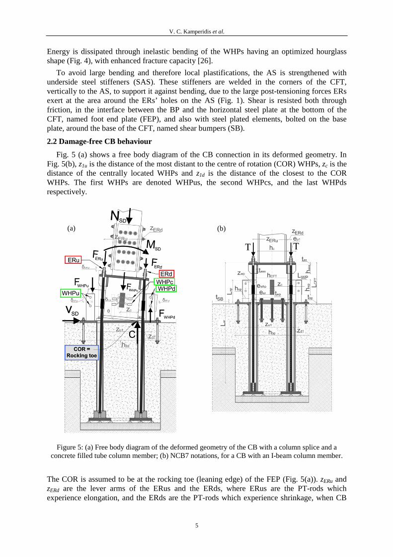
Fig. 5 (a) shows a free body diagram of the CB connection in its deformed geometry. In Fig. 5(b), z1u is the distance of the most distant to the centre of rotation (COR) WHPs, zc is the distance of the centrally located WHPs and z1d is the distance of the closest to the COR WHPs. The first WHPs are denoted WHPus, the second WHPcs, and the last WHPds respectively.
Figure 5: (a) Free body diagram of the deformed geometry of the CB with a column splice and a concrete filled tube column member; (b) NCB7 notations, for a CB with an I-beam column member.
The COR is assumed to be at the rocking toe (leaning edge) of the FEP (Fig. 5(a)). zERu and zERd are the lever arms of the ERus and the ERds, where ERus are the PT-rods which experience elongation, and the ERds are the PT-rods which experience shrinkage, when CB
(a) (b)

V. C. Kamperidis et al.
6
rocks. T is the initial post-tensioning at each ER, while FERu and FERd are the total force developed to the ERus and the ERds respectively. FWHPu, FWHPc and FWHPd are the forces developed at the WHPus, the WHPcs and the WHPds respectively. NSD, MSD and VSD are the design axial force, the design bending moment and the design base shear, assumed from a preliminary pushover analysis. C is the compressive force at the rocking toe of the FEP of the CFT, equal to:
C = NSD + FWHPu + FWHPc - FWHPd + FERu + FERd (1)
Fig. 6 shows the theoretical cyclic moment-rotation (M-θ) behaviour of the CB. The CB’s moment resistance M, is given by the relation:
ERWHPN MMMM ++= (2)
where MN, MWHP, and MER are the moment contributions of the axial force NSD, the WHPs, and the ERs to the total moment resistance of the CB respectively.
Figure 6: (a) Theoretical cyclic M-θ behaviour of the CB; (b) Moment contribution of the axial force NSD; (c) Moment contribution of the WHPs; (d) Moment contribution of the ERs for θ5<θERd,PTF.
After decompression of the CB (Point 1 in Fig. 6 (a)), gap opens and the behaviour of the connection becomes non-linear elastic with rotational stiffness S12. At point 2, the WHPus yield, and M continuous to increase with slope S23. At point 3, the WHPcs yield, and M continuous to increase with slope S34. At point 4, the WHPds yield and M continuous to

V. C. Kamperidis et al.
7
increase with slope S45 up to point 5, corresponding to the targeted base rotation θt, represented (in the diagram) by the rotation θ5. Upon loading reversal, the CB begins to unload until gap closes. Equations to calculate SWHP,12; SWHP,23; SWHP,34; SWHP,45; SER,15; S12; S23; S34; S34; θ2; θ3 and θ4, are provided in Section 2.3.
The MWHP-θ behaviour is considered multi-linear elastoplastic. When loading is reversed, both the WHPs and the ERs unload with their elastic stiffness up to point 6. ERs continue to unload with the same stiffness KER, until the gap closes. From point 6 to 7, WHPus unload with their post-elastic stiffness Kfp, while WHPcs and WHPds unload with their elastic stiffness Kfe. From point 7 to point 8, both WHPus and WHPcs unload with their post-elastic stiffness, while only the WHPds continue to unload with their elastic one. From point 8 to 9, all WHPs unload with their post-elastic stiffness. The axial force’s moment contribution is assumed to be of a constant magnitude (Fig. 6 (b)), due to the small values of θ, ignoring the effect of the rocking to the M-θ curve shape [27].
2.3 Design procedure for the damage-free CB
The design procedure of the new CB involves the dimensioning of its basic components (e.g. ERs, WHPs, WPs, SPs) to achieve a target connection performance. For the NCB7 connection the design procedure has the following steps:
Step 1: Calculation of the initial post-tensioning force. Select a value for the ratio MIGO/MN,pl,Rd,c, where MIGO is the moment at point 2 in Fig. 6(a) and MN,pl,Rd,c is the plastic moment of resistance of the column (member), allowing for interaction with axial force NSD. The aforementioned ratio should be less than one for the SC-MRF to have base shear strength comparable to that of conventional MRFs. Select a value for the ratio Md/MIGO, where Md is the moment contribution of both the post-tensioning and the axial force, equal to the moment at point 1 in Fig. 6(a). In past research [28, 29] Md is referred as decompression moment because it is the moment at which the gap, in the interface between the base plate and the CFT, opens. Md/MIGO should be larger than 0,5 to approximately achieve self-centering behaviour for the connection. The initial post-tensioning force T, at each PT rod, is given by the relation:
ERdERdERuERu
CFTSDD
znzn
hNMT
⋅−⋅⋅⋅−= 5.0
(3)
Step 2: Design the ERs. Select a yield strength, fy,ER, for the ERs, and assume an initial diameter DER for the rods. The yield force at each rod will be:
2,,,, 5,0 ERERyERERyiYER DfAfF ⋅⋅⋅=⋅= π (4)
where AER is the gross sectional area of each ER.
The force developed at the ERus is:
,, 0ERu ERu ER ERu ERu ERu YF n K z n Tθ θ θ= ⋅ ⋅ ⋅ + ⋅ < ≤ (5)
where θERu,Y is the base rotation at which ERus yield, equal to:

V. C. Kamperidis et al.
8
,,
y ER ERERu Y
ER ERu
f A T
K zθ
⋅ −=
⋅ (6)
where KER is the axial stiffness of each ER, given by the relation:
ER ERER
ER
E AK
L
⋅= (7)
The force at all nER ERds is given by the relation:
,, 0ERd ERd ER ERd ERd ERd PTFF n K z n Tθ θ θ= − ⋅ ⋅ ⋅ + ⋅ < < (8)
where θERd,PTF is the base rotation at which the ERds become stress-free, equal to:
,ERd PTFER ERd
T
K zθ
⋅
=⋅
(9)
Check which is the minimum between θERu,Y and θERd,PTF, according to the following relation:
, ,, ,PTF
ER Y iERuERu Y ERd
ERd
F Tz
z Tθ θ
−> ⇒ < (10)
The connection is designed to satisfy relation (10). To avoid yielding at the ERs under the design basis earthquake (DBE; 475 yrs return period), the length of the ERs must be calculated according to the following relation (θERu,Y > θDBE):
( ),
ER ER ERu DBEER DBE
y ER ER
E A zL
f A T
θ⋅ ⋅ ⋅≥⋅ −
(11)
Similarly, to avoid yielding, at the ERs, under the maximum considered earthquake (MCE; 2500 yrs return period), the length of the ERs must be calculated according to the following relation (θERu,Y > θMCE):
( ),
ER ER ERu MCEER MCE
y ER ER
E A zL
f A T
θ⋅ ⋅ ⋅≥⋅ −
(12)
Step 3: Design the WHPs. Select the number of the more distant (nWHPu), the central (nWHPc) and the closest to the COR (nWHPd) WHPs, and calculate the required yield force of each WHP FWHP,Y,i according to the relation:
[ ]1 2 2
, , 2 2 21 1
( ) ( )u IGO N ERWHP Y i
WHPu u WHPc c WHPd d
z M M MF
n z n z n z
θ θ⋅ − −=
⋅ + ⋅ + ⋅ (13)
where MER(θ2) is the total moment contribution of ERs, for base rotation θ2, equal to:
( ) ( ) ( )2 2 1ER ER ERu ERu ERd ERd ERM K n z n z Mθ θ θ= ⋅ ⋅ − ⋅ ⋅ + (14)

V. C. Kamperidis et al.
9
and MER(θ1), the total moment contribution of ERs, for base rotation θ1, equal to:
( ) ( ) ( ) ( )1 1 1ER ERu ERu ERd ERd ERu ERdM n z n z T M Mθ θ θ= ⋅ − ⋅ ⋅ = − (15)
It is initially assumed that the contribution of the ERs, to the total moment resistance of the connection, is negligible, for base rotations up to θ2 (point 2 of Fig. 6(a)). That yields:
( ) ( ) ( )2 10ER ER ERM M Mθ θ θ≅ = = (16)
Given this assumption, a first estimation of FWHP,Y,i can be derived as follows:
( )1 1
, , 2 2 21 1
u IGO N ERWHP Y i
WHPu u WHPc c WHPd d
z M M MF
n z n z n z
θ⋅ − − =⋅ + ⋅ + ⋅
(17)
According to [9], the yield strength of each WHP is given by the relation:
3
,,Y,
2
3e y WHP
WHP iWHP
D fF
L
⋅ ⋅=
⋅ (18)
where LWHP is the length of half a WHP, fy,WHP is the yield strength of the WHPs and De is its external diameter (Fig. 4(a)). Solving (18) for De, yields:
,Y,3
,
3
2WHP i WHP
ey WHP
F LD
f
⋅ ⋅=
⋅ (19)
From [9], considering (19), the internal diameter of a WHP Di is given by the relation:
( )32.57 e
iWHP
DD
Lπ⋅
=⋅
(20)
According to [9], the elastic stiffness Kfe of a WHP is given from the relation:
3
2 3
92
40 48e i
fe
e WHP WHP
D D E GK
E D L G L
π⋅ ⋅ ⋅ ⋅ ⋅= ⋅ ⋅ ⋅ ⋅ + ⋅ ⋅
(21)
According to [9], the post-elastic stiffness Kfp of a WHP is given from the relation:
fefp KK ⋅= %2 (22)
The first estimations of θ2, θ3 and θ4, are given from the relations:
, ,2
1
WHP Y i
fe u
F
K zθ =
⋅ (23)

V. C. Kamperidis et al.
10
, ,3
WHP Y i
fe c
F
K zθ =
⋅ (24)
, ,4
1
WHP Y i
fe d
F
K zθ =
⋅ (25)
The deflection of each WHP, when yielding occurs, is given from the following relation:
, ,,
WHP Y iWHP Y
fe
F
Kδ = (26)
The calculated value of 2θ is used (14) to yield a better estimation of the real value of MER.
The latter value is then substituted in relation (13), to yield an new value for FWHP,Y,i, and the WHP design process is repeated (Eq. 18-26).
Step 4: Design of the supporting plates and the web plates. The thickness of the WPs is given by the following relation, according to [26]:
, ,min2,
0.35 WHP Y i WPWP
y WP d
F Et
f k
⋅ ⋅=
⋅ (27)
where Kd is derived from [26] as follows:
1 2
1 2d
D DK
D D
⋅=+
(28)
where D1 is the diameter of the holes at the SPs, and D2 is the WHPs’ external diameter.
The thickness of the SP is also derived from [26], and is given by the following relation:
( ),min
0,52, , , , , ,
3,546
38,809 40 197
WHP plSP
WHP Y i WHP pl d y SP WHP Y i
Mt
F M K f F
⋅=
⋅ + ⋅ ⋅ ⋅ − ⋅ (29)
All rest CB’s components are designed to Eurocodes.
Step 5: Self-centering capability. To check whether the CB provides self-centering behaviour up to a desired rotation θt, the following relations should be satisfied:
( ) ( )12 23 2 23 34 3 4D tM S S S S forθ θ θ θ≥ − ⋅ + − ⋅ < (30)
( ) ( ) ( )12 23 2 23 34 3 34 45 4 4D tM S S S S S S forθ θ θ θ θ≥ − ⋅ + − ⋅ + − ⋅ ≥ (31)
If relations (30) and (31) are not satisfied, return to Step 1, and repeat the design procedure with a higher Md/MIGO ratio. The design procedure can be applied to the NCB7X CB, modifying the above relations.

V. C. Kamperidis et al.
11
2.4 Analytical hysteretic model.
The total rotational stiffness of the idealized moment-base rotation diagram of Fig. 6(a) is given by the following relations:
Points 1 to 2 (θ1 < θ ≤ θ2):
( ) ( )2 2 2 2 212 1 1fe WHPu u WHPc c WHPd d ER ERu ERu ERd ERdS K n z n z n z K n z n z= ⋅ ⋅ + ⋅ + ⋅ + ⋅ ⋅ + ⋅ (32)
Points 2 to 3 (θ2 < θ ≤ θ3):
( ) ( )2 2 2 2 223 3 1 1fe WHPu u WHPc c WHPd d ER ERu ERu ERd ERdS K n z n z n z K n z n zλ= ⋅ ⋅ ⋅ + ⋅ + ⋅ + ⋅ ⋅ + ⋅ (33)
Points 3 to 4 (θ3 < θ ≤ θ4):
( ) ( )2 2 2 2 234 3 1 3 1fe WHPu u WHPc c WHPd d ER ERu ERu ERd ERdS K n z n z n z K n z n zλ λ= ⋅ ⋅ ⋅ + ⋅ ⋅ + ⋅ + ⋅ ⋅ + ⋅ (34)
Points 4 to 5 (θ4 < θ ≤ θ5):
( ) ( )2 2 2 2 245 3 1 3 3 1fe WHPu u WHPc c WHPd d ER ERu ERu ERd ERdS K n z n z n z K n z n zλ λ λ= ⋅ ⋅ ⋅ + ⋅ ⋅ + ⋅ ⋅ + ⋅ ⋅ + ⋅ (35)
The total rotational stiffness of the unloading parts of half the first hysteretic loop, is defined by the following expression:
S56 = S12; S67 = S23; S78 = S34; S89 = S45 (36)
The values of θ at the characteristic points 6 to 9, of Fig. 6(a), are the following:
6 5 22θ θ θ= − ⋅ (37)
7 5 32θ θ θ= − ⋅ (38)
8 5 42θ θ θ= − ⋅ (39)
9 0θ = (40)
The values of the CB’s moment resistance at the characteristic points of Fig. 6(a) are the following:
( )1 , ,2CFT
D SD ERu ER u ERd ER d
hM M N n z n z T= = ⋅ + ⋅ − ⋅ ⋅ (41)
2 IGOM M= or 2 12 2DM M S θ= + ⋅ (42)
( )3 12 23 2 23 3DM M S S Sθ θ= + − ⋅ + ⋅ (43)
( ) ( )4 12 23 2 23 34 3 34 4DM M S S S S Sθ θ θ= + − ⋅ + − ⋅ + ⋅ (44)

V. C. Kamperidis et al.
12
( ) ( ) ( )5 12 23 2 23 34 3 34 45 4 45 5DM M S S S S S S Sθ θ θ θ= + − ⋅ + − ⋅ + − ⋅ + ⋅ (45)
( ) ( ) ( )6 12 23 2 23 34 3 34 45 4 45 5DM M S S S S S S Sθ θ θ θ= + − − ⋅ + − ⋅ + − ⋅ + ⋅ (46)
( ) ( ) ( )7 23 12 2 23 34 3 34 45 4 45 5DM M S S S S S S Sθ θ θ θ= + − ⋅ + − − ⋅ + − ⋅ + ⋅ (47)
( ) ( ) ( )8 23 12 2 34 23 3 34 45 4 45 5DM M S S S S S S Sθ θ θ θ= + − ⋅ + − ⋅ + − − ⋅ + ⋅ (48)
( ) ( ) ( )9 23 12 2 34 23 3 45 34 4DM M S S S S S Sθ θ θ= + − ⋅ + − ⋅ + − ⋅ (49)
3 THREE-DIMENSIONAL NONLINEAR FINITE ELEMENT MODEL
3.1 Model for the WHPs.
To simulate the cyclic behaviour of the WHPs, a three-dimensional FEM model was developed in ABAQUS [30]. Fig. 7 shows the mesh of a single WHP. WHPs were modelled using the C3D8R, which is an 8-node linear (first-order) brick, reduced-integration, hexahedral solid element, with hourglass control, available in ABAQUS.
Figure 7: 3D representation of the mesh and the seeding details of a single WHP.
The material properties of the WHPs were specified according to the coupon tests of [26] for a duplex stainless steel material (SSD). Research, reported in [26], has shown that WHPs made of SSD, have superior seismic performance. The steel grade used, aimed to achieve the required force, while keeping the dimensions of the WHPs relatively small. The nominal stress σnom – nominal strain nomε curves, were converted into piecewise linear true stress trueσ - logarithmic plastic strain ln
plε curves, as required for the material properties input in ABAQUS, according to the relations:
( )1true nom nomσ σ ε= ⋅ + (50)
( )ln ln 1pl truenom E
σε ε= + − (51)
where E is the Young’s modulus for the WHPs. Fig. 4(d) shows the boundary conditions (BCs) and the contact interactions of the WHPs-WPs-SPs system along with the WHPs’

V. C. Kamperidis et al.
13
loading modelling. Contact interactions were applied between the cylindrical external surfaces of the WHPs and the holes at the SPs. The contact-pair type of contact interaction was used to model the interaction between the WHPs and the SPs, with surface-to-surface contact discretization. A master and a slave surface were defined for that reason. The finite-sliding contact formulation tracking approach was used to account for the relative motion between the interacting surfaces. The contact algorithm enforces contact conditions in an average sense over regions nearby slave nodes, using a Lagrange multiplier formulation. The averaging regions are approximately centered on slave nodes and hence each contact constraint, predominantly, considers one slave node as well as adjacent slave nodes. The finite-sliding tracking approach allows for the arbitrary relative separation, sliding and rotation of the constrained surfaces, with connectivity of the currently active contact constraints changing upon relative tangential motion of the contacting surfaces.
Figure 8: (a) PEEQ distribution in a WHP, (b) WP’s and SP’s plastifications potential areas, (c) View cut in the uplifted WHPs for base rotation 0,028 rad.
A large number of simulations were conducted, to identify the optimum mesh refinement for all parts of the CB. A finer mesh was selected for the WHPs, were large stress
(a) (b)
(c)

V. C. Kamperidis et al.
14
concentration existed, while a coarser mesh selected for other parts of the connection where less accuracy needed. The final mesh discretization used solely hexahedral finite elements with maximum side length of 8 mm at the external parts of the WHP, while at the internal parts the refinement resulted even to size of 3 mm, as seen in Fig. 7. Coarse mesh served for the computational efficiency, where possible.
The imposed displacement history, used to simulate the cyclic loading in the FEM, consisted of 45 mm amplitude half cycles, applied at the tip of the column member (TIP). The total height of the connection, starting from the FEP up to the TIP, was 1,5 m (Fig. 9(b)).
Displacement-controlled non-linear analysis was performed along with automatic stabilization, to ensure that numerical problems due to the contact interactions will not occur.. Fig. 8(a) shows the deformed shape of a WHP, and plots - separately from the SPs and the WPs - the equivalent plastic strain (PEEQ) distribution, which corresponds to the maximum horizontal displacement, imposed at the TIP of the FEM model, as seen in Fig. 8(c). The latter displacement yields a 0,028 rad base rotation. PEEQ is defined in ABAQUS [30] as follows:
2
3p p
ij iijPEEQ ε ε= ⋅ ⋅ (52)
where pijε is the plastic strain components in the i and j directions. However, the optimized
hourglass shape of the internal parts of the WHP avoids extreme stress picks and obtains a uniform distribution of plastic deformation along its length, while PEEQ is totally absent from its external parts (Fig. 4(a)). Fig 8(b) shows the negligible ovalization - as a result of plastic deformations - at the inner circumferential edges of the SP holes, designed under the specifications of [26], while small plastic deformations occur at the bottoms of the SPs. WPs, also designed under [26], totally avoided plastic deformations. The FEM results verified the accuracy of the design rules of [26].
3.2 Model for the connection.
Fig. 9(a) shows the three-dimensional FEM model developed to represent the geometry and the characteristics of the analytical model of the connection, and to simulate its behaviour. The welded interfaces, i.e. SPs welded on the BP, SAS welded to the AS and the CFT, WPs welded to the CFT, column member welded to the AS, and AS welded to the CFT, were modelled by applying kinematic (tie) constraints to the degrees of freedom (DOFs) of the nodes at the interface between the two bodies (parts). Kinematic constraints were also applied between the WHPs’ “external” part, at the middle of the WHP, between the SBs and the BP, and also between the ERs’ washer plates (ERWs), by applying tie constraints between the two surfaces. Contact interactions were specified between surface pairs that separate after contact. The contact surface pairs in the CB, as a whole, are the following: the ERs and the AS holes, between which normal contact, using the hard contact pressure-overclosure contact enforcement method, was applied; the ERW and the AS, between which normal – hard - contact was applied; the FEP and the BP, between which normal contact and friction – with a friction coefficient of a magnitude 0,2 – was applied; the WHPs and the SPs, between which normal contact and friction was applied, with friction coefficient of a magnitude 0,2; and the SBs and the CFT, between which normal - hard - contact was applied. Mechanical-type BCs were applied at the following surfaces: at the underside surface of the BP (fully-fixity), to restraint all of its kinematic DOFs; at the bottom surface of the ERs, to obtain the full fixity of them; to the TIP, to realize the imposed displacement.

V. C. Kamperidis et al.
15
Except from the SPs and the WPs, all other parts of the connection modelled solely using the C3D8R solid element. More reduced integration elements were used in the regions were stress concentration was expected, mainly for two reasons: the first is that this kind of elements, having less integration points, provide computational efficiency without having a significant effect to the problem’s solution accuracy; the second is that in displacement-based finite element formulations, with the inclusion of plasticity phenomena, the more integration points used, the more overestimated the stiffness matrix becomes.
Figure 9: (a) Mesh of the CB, (b) Basic dimensions of the CB, (c) Dimensions of a WHP.
Hence, the use of reduced integration elements results to less stiffer elements, and thereby provides a correction to the problem. In the SPs and the WPs a small number of the C3D6 solid element was used. The C3D6 element is a 6-node linear triangular prism [31]. In general a finer mesh was applied to regions with the likelihood of large plastic deformations and buckling phenomena, while a coarser mesh applied in regions where local instabilities were not expected.
To obtain the material laws in ABAQUS, the stress-strain relations, using nominal material property values, were converted into piecewise linear true stress-logarithmic plastic strain curves according to the relations (50) and (51). The latter relations used to define the uniaxial material properties of all the components of the connection. The BP, SB, FEP, CFT, AS, SAS, ERW, and the column member were assigned to the common steel grade S355, with an elasto-plastic law with isotropic hardening rule. The WPs and the SPs were assigned to the SSD material, namely to the same material with the WHPs. The material of the ERs had nominal yield strength equal to 1050 MPa, Young’s modulus 205 GPa, and elongation capacity 7%, according to the suppliers’ specifications.
(a) (b)
(c)

V. C. Kamperidis et al.
16
Displacement-based and pressure-based BCs were used to realize the loadings in the CB. Axial force was realized in the model, as a pressure load, applied to the whole upper surface of the TIP (Fig. 8(c)). A pressure of a magnitude 30,387 N/mm2 was implemented for that reason. A displacement-control BC was created, to reproduce the moment at the base of the column. The translational DOF, denoted U1 in ABAQUS, was assigned with a displacement value of 45 mm, in order to reproduce the equivalent moment (Fig. 8(c)). The analysis consisted of seven steps; in the second step, contact interactions were established to ensure that numerical problems due to contact formulation will be avoided in the next steps. The post-tensioning of the CB, also established at the second step, by applying an adjust-length-based bolt load, in an internal surface of the ERs, and thereby the targeted post-tensioning force T was realized. In the subsequent steps, the cyclically displacement history was established. Displacement-controlled non-linear analysis was performed. The whole CB’s FEM model consisted of 116926 nodes and 86307 elements, 84939 of which were linear hexahedral elements of type C3D8R, and 1368 linear wedge elements of type C3D6 (6-node linear triangular (wedge) prism, reduced integration, with hourglass control. The total computational time of each of the cyclic analysis was completed in 42 minutes, in an Intel(R) Core(TM) i7-3770 CPU @ 3.40 GHz (8 CPUs), with 32 Gb RAM, running in 64 Windows 7 environment.
3.3 Assessment of the finite element model.
Fig. 10 plots the moment-base rotation hysteresis of the FEM analysis’ results, against the analytical results.
Figure 10: (a) FEM vs Analytical results for the NCB7X (4 WHPs), (b) FEM vs Analytical results for the NCB7 (8 WHPs).
The results of the analysis show that a good agreement is achieved between the FEM and the analytical model, for both CBs’ models; i.e. good agreement is obtained for the connection with the four WHPs (Fig. 1(b)), and also good agreement is obtained for the connection with the eight WHPs (Fig. 1(b)). The predicted values for the Md and MIGO, are in very good agreement between the FEM and the analytical model. For both models, the elastic stiffness is almost the same, as well as post-elastic stiffness is almost identical. Both connections were designed according to paragraph 2.4 to obtain self-centering behaviour. From the FEM analysis results, this behaviour is achieved, with good agreement for the returning moment M9 (Fig. 6(a)). Small discrepancies are observed in the thickness of the hysteretic loops between
(a) (b)

V. C. Kamperidis et al.
17
the FEM and the analytical models. This is because the analytical hysteretic model doesn’t count for plastifications in other parts of the connection rather than only in the WHPs.
However, small plastifications are observed in the FEM models, under MCE-leveled base rotations, resulting in energy dissipation and thereby broadening of the loops. Moreover, the differences in the slopes of the unloading parts of the diagrams are due to the rocking phenomenon which is a highly non-linear phenomenon.
The damage in the connection is evaluated by monitoring the plastic deformations. The latters are plotted by the PEEQ stresses. From Fig. 8(a), and 8(b), it can be seen that plastic deformations developed in the WHP holes of the SP, and in the bottoms of the SPs, in addition to those expected in the WHPs.
The comparison between the FEM analyses and the analytical model show that the analytical hysteretic model developed in paragraph 2 captures well the FEM models. It is verified this way the accuracy of the analytical model.
4 CONCLUSIONS
This paper presents a novel damage-free rocking steel post-tensioned column base (CB), with high strength steel post-tensioned rods (ERs) and energy dissipation devices, consisting of steel cylindrical pins, with an optimized hourglass shape (WHPs). The novel CB addresses the shortcomings of conventional CBs and achieves structural resilience under strong earthquakes. An analytical model has been developed for the connection, using simple mechanics and plastic analysis, to predict the CB’s hysteretic behaviour and provide design rules. A detailed non-linear finite element model (FEM) has also been developed for the new CB. Based on the findings of this paper, the following conclusions are drawn:
• The new CB achieves to be very easily inspected and repaired if damaged. It allows easy construction and deconstruction, eliminating in-situ welding, and provides potential for re-use of its structural components. Smart detailing in the new CB provides a damage-isolation mechanism, enabling damage concentration, in easy-to-replace structural elements, while all other parts of the connection remain elastic. Due to the formation of the new CB, the large post-tensioning forces are applied only to a concrete filled tube, serving as the column foot, and not to the column member. In this manner, the post-tensioned CB avoids axial shortening as a result of the post-tensioning forces. The new CB has a rotational rigidity and strength control mechanism which allows for optimum steel design. The independent tuning of stiffness and strength of the connection enables for smaller joint coefficient factors utilization and hence for smaller column sections. By tuning the basic characteristics of the ERs or/and WHPs, the connection obtains different performance objectives. With or without a column splice, it provides the option to accommodate different types of column members, i.e. I-beams or tubes, either steel or steel-concrete composite.
• The analytical hysteretic model enables for easy and good prediction of the CB’s moment resistance, rotational stiffness and hysteretic behaviour.
• The step-by-step design procedure, sizes all the new fundamental components of the connection, whilst all other components are designed to Eurocodes. In addition, identifies all the failure modes of the connection and defines the CB’s limit states. Following the design procedure, the novel CB obtains self-centering behaviour and enhanced energy dissipation, while keeping its moment resistance and rotational stiffness to the same levels as a conventional CB connection.

V. C. Kamperidis et al.
18
• The FEM predicts and simulates well the structural properties of the CB and its hysteretic behaviour. The model permits a thorough investigation of the stress state in the connection and can be used to identify the possible failure modes and limit states. FEM analysis showed that the CB can undergo large deformations, with high energy dissipation characteristics, and avoid damage in all no-replaceable parts; damage for drift levels equal to those expected under either design basis earthquake, or the maximum considered earthquake, is isolated in the WHPs, nevertheless negligible plastic deformations occurred at the bottoms of the supporting plates and at the WHP holes at the supporting plates, without affecting - though - the connection’s overall behaviour. Thus, repair can be achieved without welding or bolting. FEM analysis showed that anchor stand stiffeners are necessary to prevent unwanted minor bending at the anchor stand, due to the increase of the post-tensioning forces. The FEM analysis’ results verified the accuracy of the analytical hysteretic model.
• The NCB7X connection (4 WHPs) obtains better agreement with the analytical model, compared with the NCB7 (8 WHPs). That is due to the fact that the four central WHPs in the NCB7 connection are subjected in a more complex loading than the ones in the NCB7X, which are subject in pure bending.
• Different column section geometries, in the base storey, and/or utilization of higher-strength steel grades for the ERs, result in shorter ERs.
• As a future research, an experimental program is planned to test the proposed connection under cyclic loading in the Lab and to provide the physical evidence of the connection’s behavior. After recalibrating the FEM model on the basis of the experimental results, the connection will be incorporated in the seismic analysis of multi-story frames to study its effect on the global seismic response.
REFERENCES
[1] EC8. Eurocode 8: Design of structures for earthquake resistance; Part 1: General rules, seismic actions and rules for buildings; 2013.
[2] Isoda, H., Lin, Y., Shimizu, H., Ozaki, F., Kawai, Y., Shaking table tests of rocking system for Japanese wood house, World Conference on Timber Engineering (WCTE), Auckland, 16-19 July 2012.
[3] Roh, H., Cimellaro, G.P., Seismic fragility evaluation of RC frame structures retrofitted with control concrete rocking column and damping technique, J Struct Eng, 15: 1069-1082, 2011.
[4] Ricles J., Sause R., Garlock M., Zhao C., Posttensioned seismic energy dissipating connections for moment resisting frames, J Struct Eng 2001; 127(2): 113-21.
[5] Christopoulos C., Filiatrault A., Uang C.M., Folz B., Posttensioned energy dissipating connections for moment-resisting steel frames, J Struct Eng ASCE 2002; 128(9): 1111-20.
[6] Chou C.C., Lai Y.J., Post-tensioned self-centering moment connections with beam bottom flange energy dissipators, J Constr Steel Res 2009; 65(10-11): 1931-41.
[7] Chou C-C, Tsai K-C, Yang W-C, Self-cenetring steel connections with steel bars and discontinuous composite slab, Earthq Eng Struct Dyn 2009; 38: 403-22.
[8] Vasdravellis G., Karavasilis T.L., Uy B., Large-scale experimental validation of steel post-tensioned connections with web hourglass pins, J Struct Eng 2013; 139(6): 1033-42.
[9] Vasdravellis G., Karavasilis T.L., Uy B., Finite element models and cyclic behaviour of self-centering post-tensioned connections with web hourglass pins, Eng Struct 2013; 52: 1-16.

V. C. Kamperidis et al.
19
[10] Dimopoulos A., Karavasilis T.L., Vasdravellis G., Uy B., Seismic design, modelling and assessment of self-centering steel frames using post-tensioned connections with web hourglass shape pins, Bulletin of Earthquake Engineering 2013; 11:1797–1816.
[11] Rojas P, Ricles JM, Sause R. Seismic performance of post-tensioned steel moment resisting frames with friction devices. J Struct Eng 2004; 131(4): 529-40.
[12] Kim H.J., Christopoulos C., Friction damped posttensioned self-centering steel moment-resisting frames, Journal of Structural Engineering 2008; 134(11): 1768-1779.
[13] Tsai K.C., Chou C.C., Lin C.L., Chen P.C., Jhang S.J., Seismic self-centering steel beam-to-column moment connections using bolted friction devices, Earthquake Engineering and Structural Dynamics 2008; 37: 627-645.
[14] Wolski M., Ricles J.M., Sause R., Experimental study of a self-centering beam-column connection with bottom flange friction device, J Struct Eng 2009; 135(5): 479-488. [15] Ricles J., Sause R., Garlock M., Zhao C., Post-tensioned seismic resistant connections for steel frames, J Struct Eng 2001; 127(2): 113-21.
[15] Garlock, M., Full-scale testing, seismic analysis, and design of post-tensioned seismic resistant connections for steel frames, Ph.D. Dissertation: Civil and Env. Engineering Dept., Lehigh University, Bethlehem, PA, 2002.
[16] Dimopoulos A.I., Karavasilis T.L., Vasdravellis G, Seismic design, modelling and assessment of self-centering steel frames using post-tensioned connections with web hourglass shape pins, Bull Earthquake Eng 2013; 11 (5), 1797-1816
[17] Borzouie, J., Rodgers, G. W., MacRae, G. A., Chase, J. G., Clifton C. G., Moghadam, A. S., Base connections seismic sustainability and base flexibility effects, Steel Innovation Conference 2013, Christchurch, New Zealand, February 2013.
[18] Chi, H., Liu, J., Seismic behavior of post-tensioned column base for steel self-centering moment resisting frame, Journal of Constructional Steel Research 78 (2012) 117–130
[19] Ikenaga M., Nagae T, Nakashima M., and Suita K. Development of Column Bases Having Self-Centering and Damping Capability, Behaviour of Steel Structures in Seismic Areas, STESSA; 2006. p. 703-8.
[20] Ikenaga, M., Nakashima, M., Nagae, T., Reduction of residual story drift of moment resisting frames using self-centering column bases, Behaviour of steel structures in seismic areas, STESSA; 2009. p. 465-71.
[21] Chou, C-C, Chen, J-H, Analytical model validation and influence of column bases for seismic responses of steel post-tensioned self-centering MRF systems, Eng Struct 2011; 33: 2628-43.
[22] EC3. Eurocode 3: Design of steel structures; Part 1-1: General rules and rules for steel buildings; 2010.
[23] EC3. Eurocode 3: Design of steel structures; Part 1-8: Design of Joints; 2005.
[24] EC4. Eurocode 4: Design of composite steel and concrete structures; Part 1-1: General rules and rules for buildings; 2004.
[25] VSL International LTD (www.vsl.com).
[26] Vasdravellis G., Karavasilis T.L., Uy B., Design rules, experimental evaluation, and fracture models for high-strength and stainless steel hourglass shape energy dissipation devices, Journal of Structural Engineering 2014; 140(11): 04014087.
[27] Barthes C.B., PhD thesis. Design of Earthquake Resistant Bridges Using Rocking Columns, University of California, Berkeley. 2012.
[28] Garlock M., Sause R., Ricles J.M., Behavior and design of posttensioned steel frame systems. Journal of Structural Engineering 2007; 133(3): 389-399.
[29] Kim H.J., Christopoulos C., Seismic design procedure and seismic response of post-tensioned self-centering steel frames. Earthquake Engineering and Structural Dynamics 2008; 38(3): 355-376.

V. C. Kamperidis et al.
20
[30] Abaqus/CAE 6.13 [Computer software]. Dassault Systemes, 2014.