IC-F5061/D F5063 F6061/D F6063 Instruction Manual THIS INSTRUCTION MANUAL — Th s nstruct on manual...
24
INSTRUCTION MANUAL VHF MOBILE TRANSCEIVER iF5063 iF5061/D UHF MOBILE TRANSCEIVER iF6063 iF6061/D
Transcript of IC-F5061/D F5063 F6061/D F6063 Instruction Manual THIS INSTRUCTION MANUAL — Th s nstruct on manual...

INSTRUCTION MANUAL
VHF MOBILE TRANSCEIVER
iF5063iF5061/D
UHF MOBILE TRANSCEIVER
iF6063iF6061/D
�
READ ALL INSTRUCTIONS carefully and com-pletely before us�ng the transce�ver.
SAVE THIS INSTRUCTION MANUAL — Th�s �nstruct�on manual conta�ns �mportant operat�ng �nstruct�ons for the IC-F5061/D, IC-F5063 VHF MOBILE TRANSCEIV-ERS, IC-F6061/D, IC-F6063 UHF MOBILE TRANSCEIV-ERS.
See the operat�ng gu�de for deta�ls of BIIS, MDC, LTR® and D�g�tal system operat�ons. Ask your dealer for deta�ls.
Icom, Icom Inc. and the logo are reg�stered trademarks of Icom Incor-porated (Japan) �n the Un�ted States, the Un�ted K�ngdom, Germany, France, Spa�n, Russ�a and/or other countr�es.LTR �s a reg�stered trademark of the E.F.Johnson Company.All other products or brands are reg�stered trademarks or trademarks of the�r respect�ve holders.
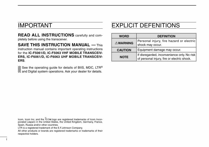
IMPORTANT EXPLICIT DEFENITIONS
WORD DEFINITION
RWARNINGPersonal �njury, f�re hazard or electr�c shock may occur.
CAUTION Equ�pment damage may occur.
NOTEIf d�sregarded, �nconven�ence only. No r�sk of personal �njury, fire or electr�c shock.

RWARNING! NEVER connect the transce�ver to an AC outlet. Th�s may pose a fire hazard or result �n an electr�c shock.
RWARNING! NEVER connect the transce�ver to a power source of more than 16 V DC such as a 24 V battery. Th�s connect�on w�ll ru�n the transce�ver.
RWARNING! NEVER cut the DC power cable be-tween the DC plug and fuse holder. If an �ncorrect connec-t�on �s made after cutt�ng, the transce�ver m�ght be damaged.
RWARNING! NEVER place the transce�ver where normal operat�on of the veh�cle may be h�ndered or where �t could cause bod�ly �njury.
CAUTION! NEVER allow ch�ldren to touch the trans-ce�ver.
CAUTION! NEVER expose the transce�ver to ra�n, snow or any l�qu�ds.
USE the spec�fied m�crophone only. Other m�crophones have d�fferent p�n ass�gnments and may damage the transce�ver.
DO NOT use or place the transce�ver �n areas w�th tem-peratures below –30°C (–22°F) or above +60°C (+140°F), or �n areas subject to d�rect sunl�ght, such as the dashboard.
DO NOT operate the transce�ver w�thout runn�ng the ve-h�cle’s eng�ne. The veh�cle’s battery w�ll qu�ckly run out when the transce�ver transm�ts wh�le the veh�cle’s eng�ne �s OFF.
DO NOT place the transce�ver �n excess�vely dusty env�-ronments.
DO NOT place the transce�ver aga�nst walls. Otherw�se heat d�ss�pat�on w�ll be obstructed.
DO NOT use chem�cal agents such as benz�ne or alcohol when clean�ng, as they damage the transce�ver surfaces.
BE CAREFUL! The transce�ver w�ll become hot when operat�ng cont�nuously for long per�ods.
For U.S.A. onlyCAUTION! Changes or mod�ficat�ons to th�s transce�ver, not expressly approved by Icom Inc., could vo�d your author�ty to operate th�s transce�ver under FCC regulat�ons.
Icom opt�onal equ�pment �s des�gned for opt�mal perform-ance when used w�th th�s transce�ver. We are not respon-s�ble for the transce�ver be�ng damaged or any acc�dent caused when us�ng non-Icom opt�onal equ�pment.
PRECAUTIONS
��
���
FCC INFORMATION• FOR CLASS B UNINTENTIONAL RADIATORS:Th�s equ�pment has been tested and found to comply w�th the l�m�ts for a Class B d�g�tal dev�ce, pursuant to part 15 of the FCC Rules. These l�m�ts are des�gned to prov�de reason-able protect�on aga�nst harmful �nterference �n a res�dent�al �nstallat�on. Th�s equ�pment generates, uses and can rad�ate rad�o frequency energy and, �f not �nstalled and used �n ac-cordance w�th the �nstruct�ons, may cause harmful �nterfer-ence to rad�o commun�cat�ons. However, there �s no guaran-tee that �nterference w�ll not occur �n a part�cular �nstallat�on. If th�s equ�pment does cause harmful �nterference to rad�o or telev�s�on recept�on, wh�ch can be determ�ned by turn�ng the equ�pment off and on, the user �s encouraged to try to cor-rect the �nterference by one or more of the follow�ng meas-ures:
• Reor�ent or relocate the rece�v�ng antenna. • Increase the separat�on between the equ�pment and re-
ce�ver. • Connect the equ�pment �nto an outlet on a c�rcu�t d�ffer-
ent from that to wh�ch the rece�ver �s connected. • Consult the dealer or an exper�enced rad�o/TV techn�-
c�an for help.
VOICE CODING TECHNOLOGY
The AMBE+2™ vo�ce cod�ng Technology embod�ed �n th�s product �s protected by �ntellectual property r�ghts �nclud�ng patent r�ghts, copyr�ghts and trade secrets of D�g�tal Vo�ce Systems, Inc. Th�s vo�ce cod�ng Technology �s l�censed solely for use w�th�n th�s Commun�cat�ons Equ�pment. The user of th�s Technology �s expl�c�tly proh�b�ted from attempt�ng to extract, remove, decomp�le, reverse eng�neer, or d�sassemble the Object Code, or �n any other way convert the Object Code �nto a human-readable form. U.S. Patent Nos.#5,870,405, #5,826,222, #5,754,974, #5,701,390, #5,715,365, #5,649,050, #5,630,011, #5,581,656, #5,517,511, #5,491,772, #5,247,579, #5,226,084 and #5,195,166.

�v
TABLE OF CONTENTSIMPORTANT .......................................................................... �EXPLICIT DEFINITIONS ....................................................... �PRECAUTIONS .................................................................... ��VOICE CODING TECHNOLOGY ........................................ ���FCC INFORMATION ........................................................... ���TABLE OF CONTENTS ....................................................... �v
1 PANEL DESCRIPTION ................................................1−7 ■ Front panel ...................................................................1 ■ Funct�on d�splay ...........................................................2 ■ Programmable funct�on keys ........................................3
2 BASIC OPERATION ..................................................8−13 ■ Turn�ng power ON ........................................................8 ■ Channel select�on .........................................................8 ■ Call procedure ..............................................................9 ■ Rece�v�ng and transm�tt�ng ...........................................9 ■ User set mode ............................................................12 ■ Scrambler funct�on .....................................................13 ■ Emergency transm�ss�on ............................................13 ■ Stun funct�on ..............................................................13 ■ Pr�or�ty A channel select�on ........................................13
3 CONNECTION AND MAINTENANCE ....................14−16 ■ Rear panel connect�on ...............................................14 ■ Suppl�ed Accessor�es .................................................15 ■ Mount�ng the transce�ver ............................................15 ■ Antenna ......................................................................16 ■ Fuse replacement ......................................................16 ■ Clean�ng .....................................................................16 ■ Opt�ons .......................................................................16
4 SAFETY TRAINING INFORMATION .............................17
12345678910111213141516

Icom Inc.
q e
y
SpeakerFunction display (p. 2)w r
t
■ Front panel
q AF VOLUME CONTROL KNOB [VOL] Rotate the knob to adjust the des�red aud�o output level. • M�n�mum aud�o level �s pre-programmed.
wLED INDICATOR ➥ L�ghts red wh�le transm�tt�ng a s�gnal. ➥ L�ghts green wh�le rece�v�ng a s�gnal.
e UP/DOWN KEYS [CH Up]/[CH Down] Push to select an operat�ng channel, etc. * The des�red funct�on can be ass�gned by your dealer. (p. 3)
rPOWER SWITCH [ ] Push and hold for 1 sec. to turn the power ON and OFF. • Automat�c scan start, Password prompt and Set mode access
are ava�lable at power ON.
tDEALER-PROGRAMMABLE KEYS Des�red funct�ons can be programmed �ndependently by
your dealer. (p. 3)
yMICROPHONE CONNECTOR Connect the suppl�ed or opt�onal m�crophone. NEVER connect non-spec�f�ed m�crophones. The p�n
ass�gnments may be d�fferent and the transce�ver may be damaged.
D MICROPHONEThe suppl�ed m�crophone has a PTT sw�tch and a hanger hook.• The follow�ng funct�ons are ava�lable when the m�crophone �s on or
off hook (depend�ng on the sett�ng): - Automat�c scan starts when �t �s on hook. - Scan �s cancelled when �t �s off hook. - Scan �s paused when �t �s off hook. - Automat�c pr�or�ty channel select�on �s ava�lable when �t �s off
hook. - Sets to ‘Inaud�ble’ cond�t�on (mute cond�t�on) when �t �s on hook. - Sets to ‘Aud�ble’ cond�t�on (unmute cond�t�on) when �t �s off hook.
1
1 PANEL DESCRIPTION

■ Function display
Icom Inc.
!1
q w e r t y u i o
!0
qSIGNAL STRENGTH INDICATOR Ind�cates relat�ve s�gnal strength level as below.
Weak Receive Signal level Strong
wLOW POWER INDICATOR Appears when low output power �s selected.
e AUDIBLE INDICATOR ➥ Appears when the channel �s �n the ‘aud�ble’ (unmute)
cond�t�on. ➥ Appears when the spec�f�ed 2/5-tone/BIIS*1/MDC*2
code �s rece�ved.
r COMPANDER INDICATOR Appears when the compander funct�on �s act�vated.
t SCRAMBLER INDICATOR Appears when the vo�ce scrambler funct�on �s act�vated.
y BELL INDICATOR Appears/bl�nks when the spec�f�c 2/5-tone/BIIS*1/MDC*2
code �s rece�ved, accord�ng to the pre-programm�ng.
u CALL CODE MEMORY INDICATOR ➥ Appears when the call code memory �s selected. ➥ Appears when a phone call �s rece�ved.*3
i SCROLL INDICATOR Appears when the SDM, �ncludes more than 12 charac-
ters, �s selected dur�ng the rece�ved message select�on mode*1.
o SDM INDICATOR Appears when an SDM �s rece�ved, or a transm�t SDM �s
selected.*1
!0 ALPHANUMERIC DISPLAY ➥ D�splays an operat�ng channel number, channel name,
Set mode contents, DTMF code, etc. ➥ The �nd�cat�on mode can be selected from 1 l�ne or 2
l�nes. Ask your dealer for deta�ls. • In th�s �nstruct�on manual, the LCD �llustrat�on �s descr�bed
us�ng the 2 l�nes �nd�cat�on mode.
!1 ACTIVATED KEY INDICATOR Appears above the key ass�gned as [Scan A Start/Stop],
[Scan B Start/Stop], [Scan Add/Del(Tag)], [Lock], [Talk Around], [Surve�llance] and [BIIS button]*1 keys dur�ng that key �s act�vated.
*1 BIIS operat�on only *2 MDC operat�on only *3 LTR® operat�on only
See the operat�ng gu�de for deta�ls of BIIS, MDC, LTR® and D�g�tal system operat�ons. Ask your dealer for deta�ls.
2
1PANEL DESCRIPTION
12345678910111213141516

3
1 PANEL DESCRIPTION
■ Programmable function keysThe follow�ng funct�ons can be ass�gned to [UP], [DOWN], [P0], [P1], [P2], [P3] and [P4] programmable funct�on keys.Consult your Icom dealer or system operator for deta�ls con-cern�ng your transce�vers programm�ng.If the programmable funct�on names are bracketed �n the fol-low�ng explanat�ons, the spec�fic key �s used to act�vate the funct�on depends on the programm�ng.
CH UP AND DOWN KEYS ➥ Push to select an operat�ng channel.➥ Push to select a transm�t code channel after push�ng [TX
Code CH Select].➥ Push to select a DTMF channel after push�ng [DTMF Au-
tod�al].➥ Push to select a scan group after push�ng and hold�ng
[Scan A Start/Stop]/[Scan B Start/Stop] for 1 sec.
ZONE KEYPush th�s key, then select the des�red zone us�ng [CH Up]/ [CH Down].
What is “zone”?— Selected channels are ass�gned to a zone accord�ng to how they are to be used �n a group. For example, ‘Staff A’ and ‘Staff B’ are ass�gned �nto a “Bus�ness” zone, and ‘John’ and ‘C�ndy’ are ass�gned �nto a “Pr�vate” zone.
ZONE UP AND DOWN KEYSPush to select an operat�ng zone.
SCAN A KEY➥ Push to start and cancel scann�ng operat�on. • When Power ON Scan funct�on �s act�vated, push to pause the
scann�ng operat�on. And the paused scan resumes after the spec�fied t�me per�od has passed.
➥ Push and hold th�s key for 1 sec. to �nd�cate the scan l�st, then push [CH Up] or [CH Down] to select the des�red l�st.
SCAN B KEY➥ Push to start and cancel scann�ng operat�on. The scan restarts after the spec�f�ed t�me per�od has
passed when the scan (started w�th th�s key) �s cancelled by except for th�s key operat�on.
➥ Push and hold th�s key for 1 sec. to �nd�cate the scan l�st, then push [CH Up] or [CH Down] to select the des�red l�st.

4
1PANEL DESCRIPTION
1
SCAN ADD/DEL (TAG) KEY➥ Push to add or delete the selected channel to/from the
scan group. 1. Push to �nd�cate the scan group, then push [CH Up] or [CH Down]
to select the des�red group. 2. Push to add or delete the channel to/from the selected scan
group. 3. Push and hold for 1 sec. to ex�t the scan group select�on mode.➥ Push th�s key wh�le scan �s paused (a s�gnal �s detected)
on a channel (except for pr�or�ty channel,) the channel �s cleared from the scan group.
Depend�ng on the sett�ng, the cleared channel �s added to the scan group aga�n after the scan �s cancelled.
PRIO A/B KEYS➥ Push to select Pr�or�ty A or Pr�or�ty B channel.➥ Push and hold [Pr�o A (Rewr�te)] or [Pr�o B (Rewr�te)] for
1 sec. to rewr�te the operat�ng channel as the Pr�or�ty A or Pr�or�ty B channel.
MR-CH 1/2/3/4 KEYSPush to select the memory channel 1 to 4 d�rectly.
MONI (AUDI) KEY ➥ Push to mute and release the CTCSS (DTCS) or 2-tone
squelch mute. Open any squelch/deact�vate any mute wh�le push�ng and hold�ng th�s key. (LMR operat�on only)
➥ Act�vates one of (or two of) the follow�ng funct�ons on each channel �ndependently: (PMR operat�on only)
• Push and hold to un-mute the channel (aud�o �s em�tted; ‘Aud�-ble’ cond�t�on).
• Push to mute the channel (sets to ‘Inaud�ble’ only). • Push to un-mute the channel (sets to ‘Aud�ble’ only). • Push after the commun�cat�on �s fin�shed to send a ‘reset code’.
(5-tone/BIIS operat�on only)
NOTE: The un-mute cond�t�on (‘Aud�ble’ cond�t�on) may automat�cally return to the mute cond�t�on (‘Inaud�ble’ cond�t�on) after a spec�f�ed per�od depend�ng on pro-gramm�ng.
PUBLIC ADDRESS KEYPush to act�vate the Publ�c Address (PA) funct�on for vo�ce ampl�f�cat�on. When the PA funct�on �s act�vated, the aud�o output can be controlled from the transce�ver separately w�th [CH Up]/[CH Down].• Th�s funct�on �s ava�lable when the external un�t, such as a aud�o
ampl�fier, speaker, etc. �s add�t�onally connected.• Push th�s key, then speak �nto the m�crophone wh�le push�ng and
hold�ng [PTT].

5
1 PANEL DESCRIPTION
RX SPEAKER KEYPush to turn the RX speaker funct�on ON or OFF.When the RX speaker funct�on �s turned ON, the rece�ved aud�o can be heard v�a the external speaker.• Th�s funct�on �s ava�lable when the external speaker �s add�t�onally
connected.• Th�s funct�on �s useful when you are out of the veh�cle.• The aud�o output level �s l�nked to the transce�ver’s volume control.
LIGHT KEYPush to turn the transce�ver’s backl�ght ON for about 5 sec. when the backl�ght funct�on �s turned OFF �n user set mode.
LOCK KEYPush and hold to electron�cally lock all programmable keys except the follow�ng:[Mon�(Aud�)], [L�ght], [Lock], [Call] (�ncl. Call A and Call B), [Emergency], [Surve�llance], [Lone Worker] and [OPT 1/2/3].
LONE WORKER KEYPush to turn the Lone Worker funct�on ON or OFF.• If the Lone Worker funct�on �s act�vated, the Emergency funct�on �s
automat�cally turned ON after the spec�fied t�me per�od has passed w�th no operat�on �s performed.
HIGH/LOW KEYPush to select the transm�t output power temporar�ly or per-manently, depend�ng on the pre-sett�ng.• Ask your dealer for the output power level for each select�on.
TONE/RAN CH SELECT KEY➥ Wh�le �n analog mode operat�on, push to enter the con-
t�nuous tone channel select�on mode. Then select the des�red tone frequency/code sett�ng w�th [CH Up] or [CH Down]. After the select�on, push th�s key aga�n to set.
➥ Wh�le �n d�g�tal mode operat�on, push to enter the RAN channel select�on mode. Then select the des�red RAN set-t�ng w�th [CH Up] or [CH Down]. After the select�on, push th�s key aga�n to set.
➥ Wh�le �n m�xed (d�g�tal and analog) mode operat�on, push to enter the cont�nuous tone channel select�on mode. Then select the des�red tone frequency/code sett�ng w�th [CH Up] or [CH Down]. After the select�on, push th�s key to set. After that, the RAN channel select�on screen ap-pears. Select the des�red RAN sett�ng w�th [CH Up] or [CH Down]. After the select�on, push th�s key aga�n to set.
C.TONE CH ENT KEYPush to select the cont�nuous tone channel us�ng [CH Up]/[CH Down] to change the tone frequency/code sett�ng after push�ng th�s key. The selected channel rema�ns set as the cont�nuous tone channel unt�l another channel �s des�gnated as such. (Analog or m�xed mode operat�on only)
TALK AROUND KEYPush to turn the talk around funct�on ON and OFF.• The talk around funct�on equal�zes the transm�t frequency to the
rece�ve frequency for transce�ver-to-transce�ver commun�cat�on.

6
1PANEL DESCRIPTION
1WIDE/NARROW KEYPush to toggle the IF bandw�dth between w�de and narrow. (Analog or m�xed mode operat�on only)• The w�de passband w�dth can be selected from 25.0 or 20.0 kHz
us�ng the CS-F5060 cloning software. (PMR operat�on only) Ask your dealer for deta�ls.
DTMF AUTODIAL KEYPush to enter the DTMF channel select�on mode. Then select the des�red DTMF channel us�ng [CH Up]/[CH Down].After select�ng the DTMF channel, push aga�n to transm�t the selected DTMF code.
RE-DIAL KEYPush to transm�t the last-transm�tted DTMF code.• TX memor�es are cleared after turn�ng the transce�ver OFF.
CALL KEYSPush to transm�t a 2/5-tone/BIIS ID code.• Call transm�ss�on �s necessary before call�ng another stat�on
depend�ng on your s�gnall�ng system.• [Call A] and/or [Call B] may be ava�lable when your system
employs select�ve ‘Ind�v�dual/Group’ calls. Ask your dealer wh�ch call �s ass�gned to each key.
EMERGENCY KEYPush and hold to transm�t the emergency call.• The emergency call transm�ts w�th beeps; the d�splay does not
change.• The transce�ver can transm�t the emergency call s�lently or w�th the
d�splay changes depend�ng on the pre-sett�ng. Ask your dealer for deta�ls.
• If you want to cancel the emergency call, push and hold the key aga�n before transm�tt�ng the call.
• The emergency call �s transm�tted one t�me only or repeatedly unt�l rece�v�ng a control code, depend�ng on the pre-sett�ng.
SURVEILLANCE KEYPush to turn the surve�llance funct�on ON or OFF.When th�s funct�on �s turned ON, the beep �s not em�tted and the LCD backl�ght and the LED �nd�cator do not l�ght when a s�gnal �s rece�ved or a key �s pushed.
TX CODE ENTER KEY (PMR operat�on only)Push to enter the ID code ed�t mode d�rectly, for both 5-tone and MSK. Then set the des�red d�g�t us�ng [CH Up]/ [CH Down]. (p. 11)
TX CODE CHANNEL SELECT KEY➥ Push to enter the ID code channel select�on mode
d�rectly. Then set the des�red channel us�ng [CH Up]/ [CH Down]. (p. 10)
➥ Dur�ng ID code channel select�on mode, push for 1 sec. to enter the ID code ed�t mode for 5-tone and MSK. Then set the des�red d�g�t us�ng [CH Up]/[CH Down]. (p. 11)

7
1 PANEL DESCRIPTION
TX CODE CHANNEL UP/DOWN KEYSPush to select a TX code channel d�rectly.
SCRAMBLER/ENCRYPTION KEY➥ Wh�le �n analog mode operat�on, push to toggle the vo�ce
scrambler funct�on ON and OFF.➥ Wh�le �n d�g�tal mode operat�on, push to toggle the
encrypt�on transm�ss�on funct�on ON and OFF.
COMPANDER KEYPush to toggle the compander funct�on ON and OFF. The compander funct�on reduces no�se components from the transm�tted aud�o to prov�de clear commun�cat�on.
ID-MR SELECT KEY (PMR operat�on only)➥ Recalls detected ID codes. • Push th�s key, then select the ID code us�ng [CH Up]/
[CH Down]. • Up to 5 ID’s are memor�zed.➥ Push and hold for 1 sec. to erase the selected ID’s.
HOOK SCAN KEYWhen the on hook scan funct�on �s act�vated, push th�s key to d�sables on hook scan funct�on (stop scann�ng) temporar-�ly. Push th�s key aga�n to re-start scann�ng.
USER SET MODE KEY➥ Push and hold for 1 sec. to enter user set mode. • Dur�ng user set mode, push th�s key to select an �tem, and
change the value or cond�t�on us�ng [CH Up]/[CH Down].➥ Push and hold th�s key for 1 sec. aga�n to ex�t user set mode.
User set mode �s also ava�lable v�a the ‘Power ON funct�on.’ Refer to p. 12 also.
10Key ENT KEYPush to enable the connected m�crophone's 10-keypad operat�on.• The des�red memory channel, TX code channel (5-tone), ID l�st
number (d�g�tal), TX status (MSK/D�g�tal) or Short Data Message (d�g�tal) can be selected. (Depends on the pre-programm�ng.)
OPT 1/2/3 KEYSPush to control the output s�gnal level from the opt�onal un�t connector.

8
2BASIC OPERATION
12345678910111213141516
■ Turning power ONq Push and hold [ ] for 1 sec. to turn the power ON.w If the transce�ver �s programmed for a start up password,
�nput the d�g�t codes as d�rected by your dealer. • The keys as below can be used for password �nput: The transce�ver detects numbers �n the same block as �dent�cal.
Therefore “01234” and “56789” are the same.
KEY
NUMBER0
5
4
9
3
8
2
7
1
6
e When the “PASSWORD” �nd�cat�on does not clear after �nputt�ng 6 d�g�ts, the �nput code number may be �ncorrect. Turn the power off and start over �n th�s case.
■ Channel selectionSeveral types of channel select�ons are ava�lable. Methods may d�ffer accord�ng to your system set up.
NON-ZONE TYPE:To select the des�red operat�ng channel:• Push [CH Up] or [CH Down].• Push one of [MR-CH 1] to [MR-CH 4].
ZONE TYPE:To select the des�red zone:• Push [Zone], then push [CH Up] or [CH Down].• Push [Zone Up] or [Zone Down].
D Voting operationThe transce�ver automat�cally starts scann�ng when a zone, spec�fied for the vot�ng operat�on, �s selected.The vot�ng scan detects the S-meter of the repeater and automat�cally selects the strongest stat�on.
AUTOMATIC SCAN TYPE:Channel sett�ng �s not necessary for th�s type. When turn�ng power ON, the transce�ver automat�cally starts scann�ng. Scann�ng stops when rece�v�ng a call.

9
2 BASIC OPERATION
■ Call procedureWhen your system employs tone s�gnal�ng (exclud�ng CTCSS and DTCS), a call procedure may be necessary pr�or to vo�ce transm�ss�on. The tone s�gnall�ng employed may be a select�ve call�ng system wh�ch allows you to call spec�fic stat�on(s) only and prevent unwanted stat�ons from contact�ng you.
q Select the des�red TX code channel, 2/5-tone code ac-cord�ng to your System Operator’s �nstruct�ons.
• Th�s may not be necessary depend�ng on programm�ng. • Refer to pages. 10–11 for select�on.w Push [Call] (ass�gned to one of the dealer programmable
keys).e After transm�tt�ng, the rema�nder of your commun�cat�on
can be carr�ed out �n the normal fash�on.Selective calling Non-selective calling
■ Receiving and transmittingReceiving:q Push and hold [ ] for 1 sec. to turn the power ON.w Push [CH Up] or [CH Down] to select the convent�onal
system channel, �n sequence.e When rece�v�ng a call, rotate [VOL] to adjust the aud�o
output level to a comfortable l�sten�ng level.
Transmitting:Wa�t for the channel to become clear to avo�d �nterference.q Take the m�crophone off hook. • 2/5-tone mute may be released. (The ‘aud�ble’ cond�t�on �s se-
lected and BUSY �nd�cator l�ghts green.) • A pr�or�ty channel may be selected automat�cally.w Wa�t for the channel to become clear. • The channel �s busy when BUSY �nd�cator l�ghts green.e Wh�le push�ng and hold�ng [PTT], speak �nto the m�cro-
phone at your normal vo�ce level.r Release [PTT] to return to rece�ve.
IMPORTANT: To max�m�ze the readab�l�ty of your s�gnal; 1. Pause br�efly after push�ng [PTT]. 2. Hold the m�crophone 5 to 10 cm (2 to 4 �nches) from
your mouth, then speak �nto the m�crophone at a nor-mal vo�ce level.

10
2BASIC OPERATION
12345678910111213141516
D Transmitting notes• Transmit inhibit function The transce�ver has several �nh�b�t funct�ons wh�ch restr�ct transm�ss�on under the follow�ng cond�t�ons:
- The channel �s �n mute cond�t�on (‘Inaud�ble’ cond�t�on; “ ” (Aud�ble �nd�cator) does not appear.)
- The channel �s busy. - Un-matched (or matched) CTCSS �s rece�ved.
(Depend�ng on the pre-sett�ng) - The selected channel �s a ‘rece�ve only’ channel.
• Time-out timer After cont�nuous transm�ss�on for the pre-programmed t�me per�od, the t�me-out t�mer �s act�vated, caus�ng the trans-ce�ver to stop transm�tt�ng.
• Penalty timer Once the t�me-out t�mer �s act�vated, transm�ss�on �s further �nh�b�ted for a per�od determ�ned by the penalty t�mer.
D TX code channel selectionIf the transce�ver has [TX Code CH Select] ass�gned to �t, the �nd�cat�on can be toggled between the operat�ng channel number (or name) and TX code channel number (or name). When the TX code channel number (or name) �s d�splayed, [CH Up] or [CH Down] selects the TX code channel.
USING [TX CODE CH SELECT] KEY:q Push [TX Code CH Select]— a TX code channel number
(or name) appears.w Push [CH Up] or [CH Down] to select the des�red TX code
channel.e After select�ng, push [TX Code CH Select] to set. • Return to the stand-by mode.r Push [Call] to transm�t the selected TX code.
USING [TX CODE CH UP]/[TX CODE CH DOWN] KEY:If the transce�ver has a [TX Code CH Up] or [TX Code CH Down] key ass�gnment, the programmed TX code channel can be selected d�rectly when pushed.

11
2 BASIC OPERATION
D TX code number edit (PMR operat�on only)If the transce�ver has [TX Code CH Select] or [TX Code Enter] ass�gned to �t, TX code contents can be ed�ted w�th�n the allowable d�g�ts.
USING [TX CODE CH SELECT] KEY:q Push [TX Code CH Select] to enter the TX code channel
select�on mode. • Select the des�red operat�ng channel before enter�ng the TX
code channel select�on mode �f necessary.w Push [TX Code CH Select] for 1 sec. to enter the TX code
ed�t mode. • The d�g�t to be ed�ted bl�nks.e Push [TX Code CH Select] to select the des�red d�g�t to
be ed�ted.r Push [CH Up] or [CH Down] to select the des�red d�g�t.t Push [TX Code CH Select] to set. The d�g�t to the r�ght w�ll
bl�nk automat�cally.y Repeat r and t to ed�t all allowable d�g�ts.u After ed�t�ng, push [TX Code CH Select] to set. • Return to the stand-by mode.i Push [Call] to transm�t.
USING [TX CODE ENTER] KEY:q Push [TX Code Enter] to enter the TX code ed�t mode. • The d�g�t to be ed�ted bl�nks.w Push [TX Code Enter] to select the des�red d�g�t to be ed-
�ted.e Push [CH Up] or [CH Down] to select the des�red d�g�t.r Push [TX Code Enter] to set. The d�g�t to the r�ght w�ll
bl�nk automat�cally.t Repeat e and r to ed�t all allowable d�g�ts.y After ed�t�ng, push [TX Code Enter] to set. • Return to the stand-by mode.u Push [Call] to transm�t.
D DTMF transmissionIf the transce�ver has [DTMF Autod�al] ass�gned to �t, the automat�c DTMF transm�ss�on funct�on �s ava�lable. Up to 8 DTMF channels are ava�lable.
q Push [DTMF Autod�al]— a DTMF channel appears.w Push [CH Up] or [CH Down] to select the des�red DTMF
channel.e Push [DTMF Autod�al] to transm�t the DTMF code.

12
2BASIC OPERATION
2■ User set modeUser set mode �s accessed w�th [User Set Mode] and allows you to set seldom-changed sett�ngs. In th�s case you can “custom�ze” the transce�ver operat�on to su�t your prefer-ences and operat�ng style.
Entering the user set mode:q Wh�le push�ng and hold�ng [P1] and [P2], push [ ] to turn
the power ON. • Turn power OFF �n advance. • You should hold [P1] and [P2] unt�l “SET MODE” appears on
the d�splay.
[P1] [P2] [ ]
w Push and hold [P0] for 1 sec. to enter user set mode.
[P0]
e Push [P0] several t�mes to select the appropr�ate �tem. Then, push [Up] or [Down] to set the des�red level/cond�-t�on.
• Ava�lable set mode funct�ons are Backlight, LCD Contrast, Beep, Beep Level, Ringer Level, SQL Level, AF Min Level, Mic Gain, Battery Voltage, Horn, Signal Moni and Lone Worker.
[P0] [Up]/[Down]
r Push and hold [ ] for 1 sec. to turn power OFF, then ON aga�n to ex�t set mode.
[ ]
User set mode �s also ava�lable us�ng a programmable key. Please refer to p. 7 [User Set Mode] sect�on for �nstruct�ons regard�ng us�ng the key ass�gned for user set mode.
NOTE: [Up], [Down] and [P0] act�vate wh�le �n the user set mode regardless of the ass�gned key funct�ons.

13
2 BASIC OPERATION
■ Scrambler functionThe vo�ce scrambler funct�on prov�des pr�vate commun�ca-t�on between stat�ons. All vers�ons have a bu�lt-�n frequency �nvers�on type scrambler; however, an opt�onal roll�ng or non-roll�ng type �s ava�lable as well.
q Push [Scrambler] to turn the scrambler funct�on ON. • “ ” (Scrambler �nd�cator) appears.w Push [Scrambler] aga�n to turn the scrambler funct�on
OFF. • “ ” d�sappears.
■ Emergency transmissionWhen [Emergency] �s pushed for the spec�fied t�me per�od, an emergency s�gnal �s automat�cally transm�tted. (p. 6)
When [Emergency] �s pushed for the spec�fied t�me per�od, the DTMF or 5-tone* emergency s�gnal �s transm�tted once or repeatedly on the emergency channel. However, when no emergency channel �s spec�fied, the s�gnal �s transm�tted on the prev�ously selected channel.
If you want to cancel the emergency call, push and hold the key aga�n before transm�tt�ng the call.
* Depend�ng on the operat�ng model type.
■ Stun functionWhen the spec�fied ID, set as a k�ll ID, �s rece�ved, the stun funct�on �s act�vated.
When the k�ll ID �s rece�ved, the transce�ver sw�tches to the password requ�red cond�t�on. Enter�ng of the password (p. 8) �s necessary to operate the transce�ver aga�n �n th�s case.
■ Priority A channel selectionWhen one of the follow�ng operat�ons �s performed, the transce�ver selects the Pr�or�ty A channel automat�cally.
• Turn�ng the power ON The Pr�or�ty A channel �s selected each t�me the trans-
ce�ver power �s turned ON.• Status call The Pr�or�ty A channel �s selected when transm�tt�ng a sta-
tus call. (BIIS operat�on only)• Off hook. The Pr�or�ty A channel �s selected when the m�crohone �s
took off from �ts hanger.

14
3CONNECTION AND MAINTENANCE
12345678910111213141516
Antenna
Black
Red
12VBattery
SolderCrimp
NOTE: Use the terminals as shown below for the cable connections.
R CAUTION! NEVER remove the fuse-ho lder f rom the DC power cable.
q ANTENNA CONNECTORConnects to an antenna. Contact your dealer about antenna selection and placement.
q
e EXTERNAL SPEAKER JACK
w D-Sub 25-pin
Connect a 4–8 ˘ external speaker.
Connect an exter-nal unit.
r MICROPHONE HANGERConnect the supplied mi-crophone hanger to the vehicle’s ground for mi-crophone on/off hook functions. (See p. 1)
t IGNITION LEAD
ty DC POWER RECEPTACLE
Connects to a 12 V DC battery. Pay atten-tion to polarities. NEVER connect to a 24 V battery. This will damage the transceiver.
r
y
Optional speaker
w
e
Connects to a ignition line.R Do not put a pressure to
this lead.Binding to the DC power cable is recommended.
Microphone* The supplied micro-phone type is differ-ent depending on the version.
*
■ Rear panel connection
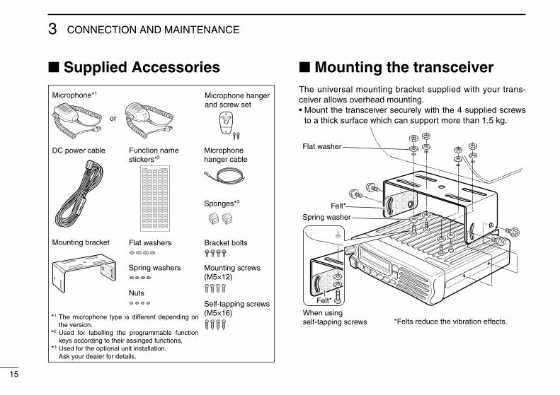
■ Supplied Accessories
Microphone*1 Microphone hanger and screw set
Microphone hanger cable
DC power cable
Sponges*3
Mounting bracket Flat washers
Spring washers
Bracket bolts
Mounting screws (M5×12)
Self-tapping screws (M5×16)
Nuts
Function name stickers*2
*3
*2
The microphone type is different depending on the version.Used for labelling the programmable function keys according to their assinged functions.Used for the optional unit installation.Ask your dealer for details.
*1
or
■ Mounting the transceiverThe un�versal mount�ng bracket suppl�ed w�th your trans-ce�ver allows overhead mount�ng.• Mount the transce�ver securely w�th the 4 suppl�ed screws
to a th�ck surface wh�ch can support more than 1.5 kg.
Flat washer
Felt*
Spring washer
When usingself-tapping screws
Felt*
*Felts reduce the vibration effects.
15
3 CONNECTION AND MAINTENANCE

16
3CONNECTION AND MAINTENANCE
12345678910111213141516
■ AntennaA key element �n the performance of any commun�cat�on systems �s an antenna. Contact your dealer for more �nfor-mat�on regard�ng antennas and how to �nstall them.
■ Fuse replacementA fuse �s �nstalled �n the suppl�ed DC power cable. If a fuse blows or the transce�ver stops funct�on�ng, track down the source of the problem �f poss�ble, and then replace the dam-aged fuse w�th a new rated one.❑ Fuse rat�ng: 20 A USE the 20 A fuse only.
■ CleaningIf the transce�ver becomes dusty or d�rty, w�pe �t clean w�th a soft, dry cloth.
AVOID the use of solvents such as benzene or alcohol, as they may damage the transce�ver sur-faces.
■ Options• RMK-3 separation kit +
OPC-607/OPC-608/OPC-609 separation cable
Allows you to �nstall the transce�ver ma�n un�t separately from the front panel for operat�ng conven�ence.
• OPC-1132/OPC-347 dc power cable
OPC-1132: 3 m (9.8 ft) OPC-347: 7 m (23 ft)
• HM-152/HM-152T/HM-148 hand microphone
HM-152 : Hand m�crophone HM-152T : DTMF m�crophone HM-148 : Heavy duty m�crophone
• SM-25 desktop microphone
• SP-5/SP-10/SP-22 external speaker
Input �mpedance : 4 ø Max. �nput power : 5 W SP-5 : Large speaker for good aud�o qual�ty. SP-10 : For all-round mob�le operat�on. SP-22 : Compact and easy-to-�nstall.
• UT-109R/UT-110R scrambler units
Non-roll�ng type (UT-109R)/Roll�ng type (UT-110R) vo�ce scrambler un�t prov�des h�gher commun�cat�on secur�ty.
• UT-96R 5tone unit
• UT-126H digital modulator/demodulator unit
Prov�des 6.25 kHz d�g�tal mode operat�on. ( UT-126H �s a upgrade vers�on of UT-119H. UT-119H can be used
depend�ng on the vers�on. Ask your dealer for deta�ls.)

Your Icom radio generates RF electromagnetic energy during transmit mode. This radio is de-signed for and classified as “Occupational Use Only”, meaning it must be used only during the course of employment by individuals aware of the hazards, and the ways to minimize such hazards. This radio is NOT intended for use by the “General Population” in an uncontrolled environment.
• For compl�ance w�th FCC and Industry Canada RF Exposure Re-qu�rements, the transm�tter antenna �nstallat�on shall comply w�th the follow�ng two cond�t�ons:
1. The transm�tter antenna ga�n shall not exceed 0 dB�. 2. IC-F5061/F5061D: The antenna �s requ�red to be located outs�de of a veh�cle and
kept at a d�stance of 48 cent�meters or more between the trans-m�tt�ng antenna of th�s dev�ce and any persons dur�ng operat�on. For small veh�cle as worst case, the antenna shall be located on the roof top at any place on the centre l�ne along the veh�cle �n order to ach�eve 48 cent�meters separat�on d�stance. In order to ensure th�s d�stance �s met, the �nstallat�on of the antenna must be mounted at least 48 cent�meters away from the nearest edge of the veh�cle �n order to protect aga�nst exposure to bystanders.
2. IC-F6061/F6061D: The antenna �s requ�red to be located outs�de of a veh�cle and
kept at a d�stance of 38 cent�meters or more between the trans-m�tt�ng antenna of th�s dev�ce and any persons dur�ng operat�on. For small veh�cle as worst case, the antenna shall be located on the roof top at any place on the centre l�ne along the veh�cle �n order to ach�eve 38 cent�meters separat�on d�stance. In order to ensure th�s d�stance �s met, the �nstallat�on of the antenna must be mounted at least 38 cent�meters away from the nearest edge of the veh�cle �n order to protect aga�nst exposure to bystanders.
To ensure that your exposure to RF electromag-netic energy is within the FCC allowable limits for occupational use, always adhere to the following guidelines:
• DO NOT operate the rad�o w�thout a proper antenna attached, as th�s may damage the rad�o and may also cause you to exceed FCC RF exposure l�m�ts. A proper antenna �s the antenna suppl�ed w�th th�s rad�o by the manufacturer or an antenna spec�fically au-thor�zed by the manufacturer for use w�th th�s rad�o.
• DO NOT transm�t for more than 50% of total rad�o use t�me (“50% duty cycle”). Transm�tt�ng more than 50% of the t�me can cause FCC RF exposure compl�ance requ�rements to be exceeded. The rad�o �s transm�tt�ng when the “TX �nd�cator” l�ghts red. You can cause the rad�o to transm�t by press�ng the “PTT” sw�tch.
Electromagnetic Interference/CompatibilityDur�ng transm�ss�ons, your Icom rad�o generates RF energy that can poss�bly cause �nterference w�th other dev�ces or systems. To avo�d such �nterference, turn off the rad�o �n areas where s�gns are posted to do so. DO NOT operate the transm�tter �n areas that are sens�t�ve to electromagnet�c rad�at�on such as hosp�tals, a�rcraft, and blast�ng s�tes.
W ARNING CAUTION
17
4 SAFETY TRAINING INFORMATION

MEMO
12345678910111213141516

1-1-32 Kam�m�nam�, H�rano-ku, Osaka 547-0003, Japan
A-6565D-1EX-ePr�nted �n Japan© 2006–2008 Icom Inc.
Pr�nted on recycled paper w�th soy �nk.