IC-F3G/F4G Instruction Manual - Icom ALL INSTRUCTIONS carefully and completely before using the...
32
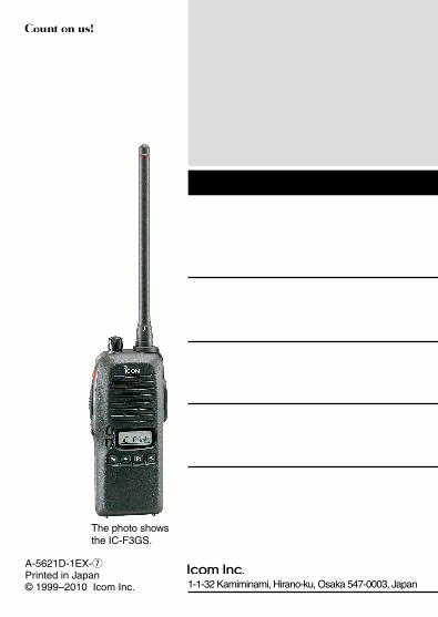
INSTRUCTION MANUAL UHF TRANSCEIVER iF4GT/GS iF3GT/GS VHF TRANSCEIVER The photo shows the IC-F3GT.
Transcript of IC-F3G/F4G Instruction Manual - Icom ALL INSTRUCTIONS carefully and completely before using the...

INSTRUCTION MANUAL
UHF TRANSCEIVER
iF4GT/GS
iF3GT/GSVHF TRANSCEIVER
The photo shows the IC-F3GT.
i
FOREWORDThank you for purchasing the IC-F3GT/GS, IC-F4GT/GS FM trans-ceiver.
READ ALL INSTRUCTIONS carefully and completely before using the transceiver.
SAVE THIS INSTRUCTION MANUAL–This instruction manual con-tains important operating instructions for the transceiver.
EXPLICIT DEFINITIONS
WORD DEFINITION
RDANGER!Personal death, serious injury or an explo-sion may occur.
RWARNING!Personal injury, fire hazard or electric shock may occur.
CAUTION Equipment damage may occur.
NOTEIf disregarded, inconvenience only. No risk of personal injury, fire or electric shock.
Icom, Icom Inc. and the Icom logo are registered trademarks of Icom Incorpo-rated (Japan) in Japan, the United States, the United Kingdom, Germany, France, Spain, Russia and/or other countries.All other products or brands are registered trademarks or trademarks of their re-spective holders.

ii
PRECAUTIONSR DANGER! NEVER short the terminals of the battery pack.
R WARNING! NEVER hold the transceiver so that the an-tenna is very close to, or touching exposed parts of the body, es-pecially the face or eyes, while transmitting. The transceiver will perform best if the microphone is 5 to 10 cm away from the lips and the transceiver is vertical.
R WARNING! NEVER operate the transceiver with a head-set or other audio accessories at high volume levels.
CAUTION: NEVER use non-Icom battery packs/chargers to prevent the loss of the transceiver’s good performance and warranty.
DO NOT push the PTT when not actually desiring to transmit.
DO NOT use or place the transceiver in direct sunlight or in areas with temperatures below –10°C or above +50°C.
DO NOT modify the transceiver for any reason.
KEEP the transceiver from the heavy rain, and NEVER immerse it in the water. The transceiver construction is water resistant, not waterproof.
Approved Icom optional equipment is designed for optimal perfor-mance when used with an Icom transceiver.Icom is not responsible for the destruction or damage to an Icom transceiver in the event the Icom transceiver is used with equip-ment that is not manufactured or approved by Icom.
iii
TABLE OF CONTENTS
FOREWORD ..................................................................................iEXPLICIT DEFINITIONS ................................................................iPRECAUTIONS ............................................................................. iiTABLE OF CONTENTS ................................................................ iii
1 PANEL DESCRIPTION ....................................................... 1−3 ■ Switches, controls, keys and connectors ..............................1 ■ Function display ....................................................................3
2 ACCESSORIES ........................................................................4 ■ Accessory attachment...........................................................4
3 BATTERY PACKS ............................................................. 5−10 ■ Battery pack replacement .....................................................5 ■ Battery cautions ....................................................................6 ■ Battery charging ....................................................................7 ■ Charging caution ...................................................................9 ■ Battery case (Option) ..........................................................10
4 PROGRAMMABLE FUNCTIONS ................................... 11−15 ■ General ...............................................................................11
5 CONVENTIONAL OPERATION ...................................... 16−18 ■ Receiving and transmitting ..................................................16 ■ Call procedure .....................................................................17 ■ Tx code channel selection ...................................................18 ■ Manual 5-tone codes ..........................................................18 ■ Transmitting notes ...............................................................18
iv
6 OTHER FUNCTIONS .............................................................19 ■ DTMF PAGER/CODE SQUELCH .......................................19
7 MAINTENANCE .....................................................................20 ■ Optional unit installation ......................................................20
8 CLONING ...............................................................................21 ■ Cloning ................................................................................21
9 OPTIONS ......................................................................... 23−24
1
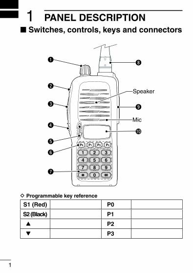
PANEL DESCRIPTION1■ Switches, controls, keys and connectors
2 3
4 5 6
7 8 9
0
1
P0 P1 P2 P3
Speaker
Mic
i
o
!0
q
w
e
r
y
u
t
D Programmable key reference
S1 (Red) P0
S2 (Black) P1
Y P2
Z P3
2
1PANEL DESCRIPTION
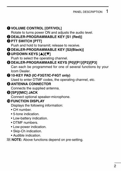
q VOLUME CONTROL [OFF/VOL] Rotate to turns power ON and adjusts the audio level.wDEALER-PROGRAMMABLE KEY [S1 (Red)]e PTT SWITCH [PTT] Push and hold to transmit; release to receive.rDEALER-PROGRAMMABLE KEY [S2(Black)]t UP/DOWN KEYS [Y]/[Z] Push to select the operating channel.yDEALER-PROGRAMMABLE KEYS [P0]/[P1]/[P2]/[P3] Can each be programmed for one of several functions by your
Icom Dealer.u 10-KEY PAD (IC-F3GT/IC-F4GT only) Used to enter DTMF codes, the operating channel, etc.i ANTENNA CONNECTOR Connects the supplied antenna.o [SP]/[MIC] JACK Connect optional speaker-microphone.!0 FUNCTION DISPLAY Displays the following information: • CH number. • 5-tone indication. • Low-battery indication. • DTMF numbers. • Low-power indication. • Skip-Ch indication. • Audible indication.
NOTE: Above functions depend on pre-setting.
PANEL DESCRIPTION1
3
■ Function display
q w e r t y u i
o
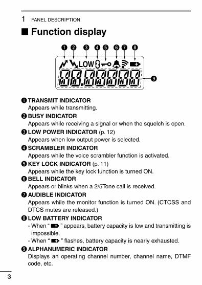
q TRANSMIT INDICATOR Appears while transmitting.
w BUSY INDICATOR Appears while receiving a signal or when the squelch is open.
e LOW POWER INDICATOR (p. 12) Appears when low output power is selected.
r SCRAMBLER INDICATOR Appears while the voice scrambler function is activated.
t KEY LOCK INDICATOR (p. 11) Appears while the key lock function is turned ON.y BELL INDICATOR Appears or blinks when a 2/5Tone call is received.
u AUDIBLE INDICATOR Appears while the monitor function is turned ON. (CTCSS and
DTCS mutes are released.)
i LOW BATTERY INDICATOR - When “ ” appears, battery capacity is low and transmitting is
impossible. - When “ ” flashes, battery capacity is nearly exhausted.
o ALPHANUMERIC INDICATOR Displays an operating channel number, channel name, DTMF
code, etc.

2ACCESSORIES
4
■ Accessory attachmentD Supplied accessoriesThe following accessories are supplied. Qty.• Battery pack ................................................................................ 1• Flexible antenna .......................................................................... 1• Belt clip (with screws) .................................................................. 1• 2251 OPT sheet* ......................................................................... 1* See p. 20 for details.
D AntennaThe antenna screws onto the transceiver as illus-trated right.
Keep the jack cover attached when jacks are not in use to avoid bad contacts.
D Belt clip Attach the belt clip to the transceiver as illustrated below.
Use the supplied screws only.
5
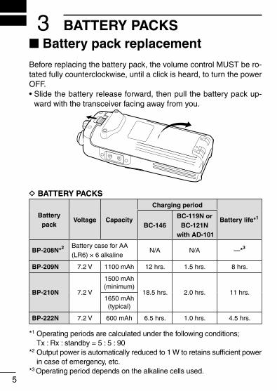
3 BATTERY PACKS■ Battery pack replacementBefore replacing the battery pack, the volume control MUST be ro-tated fully counterclockwise, until a click is heard, to turn the power OFF.• Slide the battery release forward, then pull the battery pack up-
ward with the transceiver facing away from you.
D BATTERY PACKS
Batterypack
Voltage Capacity
Charging period
Battery life*1
BC-146BC-119N or
BC-121N with AD-101
BP-208N*2 Battery case for AA(LR6) × 6 alkaline
N/A N/A —*3
BP-209N 7.2 V 1100 mAh 12 hrs. 1.5 hrs. 8 hrs.
BP-210N 7.2 V
1500 mAh(minimum)
18.5 hrs. 2.0 hrs. 11 hrs.1650 mAh(typical)
BP-222N 7.2 V 600 mAh 6.5 hrs. 1.0 hrs. 4.5 hrs.
*1 Operating periods are calculated under the following conditions; Tx : Rx : standby = 5 : 5 : 90
*2 Output power is automatically reduced to 1 W to retains sufficient power in case of emergency, etc.
*3 Operating period depends on the alkaline cells used.
6
3BATTERY PACKS
■ Battery cautionsR DANGER! NEVER short the terminals of the battery pack (or charging terminals of the transceiver). Also, current may flow into nearby metal objects such as a necklace, so be careful when placing battery packs (or the transceiver) in handbags, etc.Simply carrying with or placing near metal objects such as a neck-lace, etc. may cause shorting. This may damage not only the bat-tery pack, but also the transceiver.
R DANGER! NEVER incinerate used battery packs. Internal battery gas may cause an explosion.
R WARNING! NEVER immerse the battery pack in water. If the battery pack becomes wet, be sure to wipe it dry BEFORE attach-ing it to the transceiver.
Clean the battery terminals to avoid rust or miss contact.
Keep battery terminals clean. It’s a good idea to clean battery ter-minals once a week.
If your battery pack seems to have no capacity even after being charged, completely discharge it by leaving the power ON over-night. Then, fully charge the battery pack again. If the battery pack still does not retain a charge (or only very little charge), a new bat-tery pack must be purchased. (p. 5)

7
3 BATTERY PACKS
■ Battery charging
D Rapid charging with the BC-144NThe optional BC-144N provides rapid charging of the battery pack.The following items are additionally required:• AD-99N* and an AC adapter (not supplied with some versions). *Supplied with the charger.
BC-144N+ AD-99N
Insert together with the AD-99N.Check the orienta-tion of the AD-99N for correct charging.
Turn power OFF.
D Spacer combination.• Be sure to attach the spacer (Spacer B/
C) to the adapter (Spacer A) with the orientation as illustrated in the diagram at right.
• Attach the spacer (Spacer B/C) to the adaptor with the orientation of the stamp “ ” pointing up.
NOTE: Push the notch carefully when removing the spacer from the adaptor.
The BC-144N cannot be used in a vehicle, because the charger requires 16 V DC input.
Check orientation
and
Spacer A
Spacer B/C

8
3BATTERY PACKS
D Rapid charging with the BC-121N+AD-101The optional BC-121N allows up to 6 battery packs to be charged simultaneously.The following items are additionally required.• Six AD-101 (The spacer is supplied with the AD-101.)• An AC adapter (purchase separately).
AC adapter(Purchase separately)
Charge indicator(each indicator functions independently)
Insert together with the spacer.Check the orientation of the spacer for correct charging.
Turn power OFF.
D Regular charging with the BC-137 #11/BC-146
The optional BC-137 #11 or BC-146 provides regular charging of the battery pack.The following item is addi-tionally required:• AD-99N* and an AC adapter
(purchase separately). * Supplied with the charger. BC-137 #11
or BC-146
Insert together with AD-99N.Check the orienta-tion of AD-99N for correct charging.
Turn power OFF.
9
3 BATTERY PACKS
■ Charging cautionPrior to using the transceiver for the first time, the battery pack must be fully charged for optimum life and operation.• Recommended temperature range for charging: Between +10°C and +40°C.• Use the optional charger (BC-119N/BC-121N/BC-144N for rapid
charging, BC-137 #11/BC-146 for regular charging) only. NEVER use other manufacturers’ chargers.
The battery pack contains a rechargeable battery.Charge the battery pack before first operating the transceiver, or when the battery pack becomes exhausted.If you want to prolong the battery life, the following points should be observed:• Avoid over charging. The charging period should be less than
20 hours.• Use the battery pack until it becomes almost completely ex-
hausted under normal conditions. We recommend battery charg-ing after transmitting becomes impossible.
D Battery pack lifeWhen the operating period becomes extremely short even after charging the battery pack fully, a new battery pack is needed.
10
3BATTERY PACKS
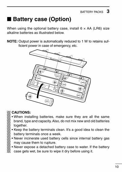
■ Battery case (Option)When using the optional battery case, install 6 × AA (LR6) size alkaline batteries as illustrated below.
NOTE: Output power is automatically reduced to 1 W to retains suf-ficient power in case of emergency, etc.
CAUTIONS:• When installing batteries, make sure they are all the same
brand, type and capacity. Also, do not mix new and old batteries together.
• Keep the battery terminals clean. It’s a good idea to clean the battery terminals once a week.
• Never incinerate used battery cells since internal battery gas may cause them to rupture.
• Never expose a detached battery case to water. If the battery case gets wet, be sure to wipe it dry before using it.
■ GeneralIn the following explanations, programmable function names are bracketed, the specific switch used to activate the function depends on programming.
D KEYPAD LOCK FUNCTIONThis function locks access to all programmable switches (except the switch assigned for the lock function).
Push and hold the [LOCK] switch for 1 sec. to toggle the lock func-tion ON and OFF.• “ ”appears while the lock function is ON.• This function may be inhibited on some channels.
D PRIORITY CHANNELThis function is used to select a pre-programmed channel at the push of a switch.
Push the [PRIORITY] switch to select the priority channel.• “PRIO” appears briefly, then the priority channel is automatically se-
lected.
D SCAN FUNCTIONThe scan function allows you to search a pre-programmed group of channels for signals.
Push the [SCAN] switch to start/stop scan.• Scan pauses on a channel when receiving a signal.• Depending on programming, a message may appear while scanning.• “Lockout SCAN” (pre-programmed list SCAN) or “Priority SCAN” can
be pre-programmed.• When the “Power-save function” is activated, the transceiver checks
all pre-programmed channels then returns to the “Power-save func-tion” again.
11
4 PROGRAMMABLE FUNCTIONS

12
4PROGRAMMABLE FUNCTIONS
D HIGH/LOW OUTPUT POWERThis function selects high or low output power for a channel.
Push the [HIGH/LOW] switch to toggle the transmit output power between high and low.• “LOW” appears when low output power is selected.
D SCRAMBLER FUNCTION (An UT-109 #01* or UT-110 #01* is required.)
This function provides higher communication security.UT-109 : Non-rolling type. 32 code numbers are available.UT-110 : Rolling type. 1020 (4 groups × 255) code numbers are
available.
Push the [SCRM] switch to toggle the function ON and OFF.
NOTE: NEVER use #02 High AF level version of the scrambler unit, as they are not compatible.
D BEEP FUNCTIONThis function provides confirmation beep tones when pushing switches.
Push the [BEEP] switch to toggle the function ON and OFF.
13
4 PROGRAMMABLE FUNCTIONS
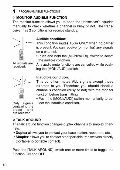
D MONITOR AUDIBLE FUNCTIONThe monitor function allows you to open the transceiver’s squelch manually to check whether a channel is busy or not. The trans-ceiver has 2 conditions for receive standby:
All signals arereceived.
2 3
4 5 6
7 8 9
0
1
P0 P1 P2 P3
Audible condition:This condition mutes audio ONLY when no carrier is present. You can receive (or monitor) any signals on a channel.• Push and hold the [MONI/AUDI], switch to select
the audible condition.Any audio mute functions are cancelled while push-ing the [MONI/AUDI] switch.
2 3
4 5 6
7 8 9
0
1
P0 P1 P2 P3
Only signals containing the proper tone are received.
Inaudible condition:This condition mutes ALL signals except those directed to you. Therefore you should check a channel’s condition (busy or not) with the monitor function before transmitting.• Push the [MONI/AUDI] switch momentarily to se-
lect the inaudible condition.
D TALK AROUNDThe talk around function changes duplex channels to simplex chan-nels. • Duplex allows you to contact your base station, repeaters, etc. • Simplex allows you to contact other portable transceivers directly
(portable-to-portable contact).
Push the [TALK AROUND] switch one or more times to toggle the function ON and OFF.

14
4PROGRAMMABLE FUNCTIONS
D DTMF TRANSMISSIONThis function allows you to send a pre-programmed DTMF code to control a repeater, open another transceiver’s squelch, etc.
Manual transmission:Push desired digit keys in sequence while pushing [PTT].• Pushing [PTT] may not be necessary depending on programming.
Automatic pre-programmed transmission:q Push the [DTMF] switch to select DTMF autodial mode, then
push [Y] or [Z] to select the desired channel.w Push the [DTMF] switch once more to send a DTMF code.
D DTMF RE-DIAL FUNCTIONThis function allows you to transmit the last-used DTMF code at the push of a key.
Push the [DTMF RE-DIAL] switch momentarily to activate the func-tion.• The previously transmitted DTMF code is automatically transmitted.• If no code has been transmitted since turning the power ON, this func-
tion does not activate.
D EMERGENCY FUNCTIONThe emergency function allows you to send your ID quickly and easily to your Base Station, etc. in case of emergency.
Push and hold the [EMERGENCY] switch for 1 sec. to activate the emergency function.• The transceiver selects a pre-programmed channel, then sends an
emergency signal to your Base Station.• The pre-programmed channel remains selected until a control signal
is received from the Base Station, or power is turned OFF.• The emergency call is repeatedly transmitted at pre-programmed in-
tervals.

15
4 PROGRAMMABLE FUNCTIONS
D DISPLAY LIGHTINGThe function display has 3 backlight conditions.OFF : No backlight.AUTO : When any key is pushed, the backlight turns ON
for 5 sec. automatically.CONTINUOUS : Backlight stays ON continuously.

16
5CONVENTIONAL OPERATION■ Receiving and transmitting
CAUTION: Transmitting without an antenna may damage the transceiver. See p. 4 for antenna attachment.Turn power ON as described on p. 2.
Receiving:q Push [Y]/[Z] to select a channel.w Listen for a transmission and adjust [VOL] to a comfortable lis-
tening level. • When no transmission is heard, push and hold monitor while
adjusting [VOL] (your transceiver may not be programmed with the monitor function).
The transceiver is now set to receive desired calls on the selected channel.
Transmitting:Wait for the channel to become clear to avoid interference.q While pushing and holding [PTT], speak into the microphone at
a normal voice level. • When a tone signalling system is used, the call procedure de-
scribed at right may be necessary.w Release [PTT] to return to receive.
IMPORTANT: To maximize the readability of your transmitted sig-nal, pause a few sec. after pushing [PTT], hold the microphone 5 to 10 cm from your mouth and speak at a normal voice level.
17
5 CONVENTIONAL OPERATION
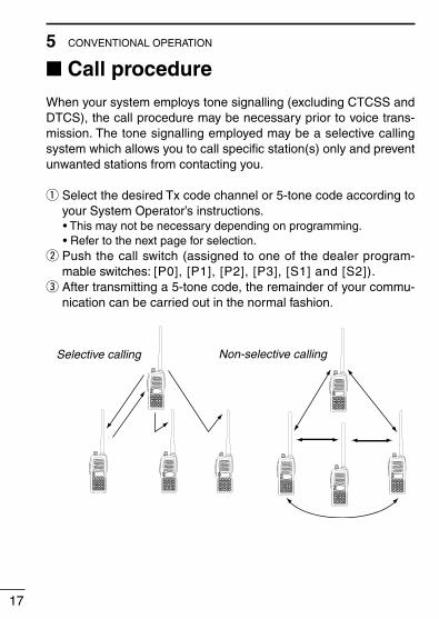
■ Call procedureWhen your system employs tone signalling (excluding CTCSS and DTCS), the call procedure may be necessary prior to voice trans-mission. The tone signalling employed may be a selective calling system which allows you to call specific station(s) only and prevent unwanted stations from contacting you.
q Select the desired Tx code channel or 5-tone code according to your System Operator’s instructions.
• This may not be necessary depending on programming. • Refer to the next page for selection.w Push the call switch (assigned to one of the dealer program-
mable switches: [P0], [P1], [P2], [P3], [S1] and [S2]).e After transmitting a 5-tone code, the remainder of your commu-
nication can be carried out in the normal fashion.
2 3
4 5 6
7 8 9
0
1
P0 P1 P2 P3
2 3
4 5 6
7 8 9
0
1
P0 P1 P2 P3
2 3
4 5 6
7 8 9
0
1
P0 P1 P2 P3
2 3
4 5 6
7 8 9
0
1
P0 P1 P2 P3
2 3
4 5 6
7 8 9
0
1
P0 P1 P2 P3
2 3
4 5 6
7 8 9
0
1
P0 P1 P2 P3
2 3
4 5 6
7 8 9
0
1
P0 P1 P2 P3
2 3
4 5 6
7 8 9
0
1
P0 P1 P2 P3
Non-selective callingSelective calling
18
5CONVENTIONAL OPERATION
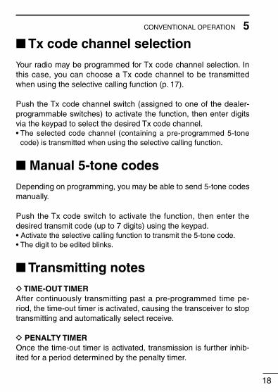
■ Tx code channel selectionYour radio may be programmed for Tx code channel selection. In this case, you can choose a Tx code channel to be transmitted when using the selective calling function (p. 17).
Push the Tx code channel switch (assigned to one of the dealer-programmable switches) to activate the function, then enter digits via the keypad to select the desired Tx code channel.• The selected code channel (containing a pre-programmed 5-tone
code) is transmitted when using the selective calling function.
■ Manual 5-tone codesDepending on programming, you may be able to send 5-tone codes manually.
Push the Tx code switch to activate the function, then enter the desired transmit code (up to 7 digits) using the keypad.• Activate the selective calling function to transmit the 5-tone code.• The digit to be edited blinks.
■ Transmitting notesD TIME-OUT TIMERAfter continuously transmitting past a pre-programmed time pe-riod, the time-out timer is activated, causing the transceiver to stop transmitting and automatically select receive.
D PENALTY TIMEROnce the time-out timer is activated, transmission is further inhib-ited for a period determined by the penalty timer.
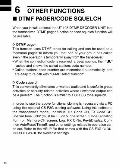
■ DTMF PAGER/CODE SQUELCHWhen you install optional the UT-108 DTMF DECODER UNIT into the transceiver, DTMF pager function or code squelch function will be available.
D DTMF pagerThis function uses DTMF tones for calling and can be used as a “common pager” to inform you that one of your group has called even if the operator is temporarily away from the transceiver.• When the connection code is received, a beep sounds, then “ ”
flashes and shows the called stations code number.• Called stations code number are memorised automatically, and
are easy to re-call with “ID-MR select function”.
D Code squelchThis conveniently eliminates unwanted audio and is useful in group activities or security related activities where unwanted output can be a problem. The function is similar to a CTCSS tone squelch.
In order to use the above functions, cloning is necessary via a PC using the optional CS-F3G cloning software. Using this software, the transceiver’s model, individual RX Code CH, TX Code CH, Special Tone Link2 (must be ‘E’) on 5Tone screen, 5Tone Signaling Form on Memory-CH screen, Log, RX C-No, Key&Display, Com-mon AutoReset TimerB, and other settings related to operation can be set. Refer to the HELP file that comes with the CS-F3G CLON-ING SOFTWARE for available settings.
19
6 OTHER FUNCTIONS

20
7MAINTENANCE■ Optional unit installation
You can install an optional unit in the transceiver.
q Remove the optional connector access cover (named 2251 OPT sheet).
• Insert a screwdriver into the hollow of the chassis, then lift and take away the cover. (The cover can not be used again.)
q
w Install the desired optional unit. Insert tightly to avoid a bad con-nection.
e Remove the paper backing of 2251 OPT sheet supplied as an accessory.
r Attach the new 2251 OPT sheet to the service window.t Program the necessary information with the cloning software
before operation. Please ask your dealer or system operator for details.
r
we

■ CloningCloning allows you to quickly and easily transfer the programmed contents from one transceiver to another transceiver; or data from PC to a transceiver using the optional CS-F3G cloning software.
D Transceiver-to-transceiver cloningq Connect the optional OPC-474 cloning cable to the [SP] jack of
the master and slave transceivers. • The master transceiver is used to send data to the slave trans-
ceiver.w While pushing [P0] and [Y], turn the transceiver’s power on to
enter cloning mode (For both the master transceiver and slave transceiver).
• “CLONE” appears and the transceiver enters the clone standby condition.
e Push [PTT] on the master transceiver. • “CLOUT” appears in the master transceiver’s display. • “CL IN” appears automatically in the slave transceiver’s display. • When cloning is finished, “CLONE” appears in the master trans-
ceiver’s display. NOTE: DO NOT push the [PTT] on the slave transceiver during clon-
ing. This will cause a cloning error.r When cloning is finished, turn power off, then on again to return
to normal operation.
NOTE: Transceiver-to-transceiver cloning can not be done between 40CH version and 100CH version, or CPU Rev.1.✻
and Rev.2.0.
• While pushing [P3] and [Y], turn the transceiver’s power on to enter CPU version check mode. CPU revision is displayed (“100CH” display for 100CH version only).
21
8 CLONING

22
8CLONING
D PC-to-transceiver cloningPlease refer to the HELP file that comes with the CS-F3G cloning software.
CAUTION: Imprudent cloning operation causes a cloning error. In such a case, memory contents may be lost. Cloning must then be repeated.

D BATTERY PACKS• BP-208N battery case
Battery case for 6 × AA (LR6) cells• BP-209N ni-cd battery pack
Voltage : 7.2 V Capability : 1100 mAh• BP-210N ni-mh battery pack
Voltage : 7.2 V Capability : 1500 mAh (minimum)/1650 mAh (typical)• BP-222N ni-cd battery pack
Voltage : 7.2 V Capability : 600 mAh
D REGULAR CHARGERS• BC-137 (#11) battery charger + BC-122 ac adaptor
• BC-146 battery charger + BC-147S ac adaptor
D RAPID CHARGERS• BC-144N desktop charger + BC-145S ac adaptor
• BC-121N multi-charger + AD-101 charger adapter (6 pcs.) + BC-157S ac adapter
• BC-119N desktop charger + AD-101 charger adapter + BC-145S ac adapter
D INTERNAL UNITS• UT-96 5tone unit
• UT-108 dtmf decoder unit
• UT-109/UT-110 voice scrambler units
23
9 OPTIONS
24
9OPTIONS
D OTHER OPTIONS• HM-131L speaker-microphone
• HS-51 head set
Allows you hands-free operation. Includes PTT and TOT.• VS-1L vox/ptt case + HS-94/HS-95/HS-97
HS-94 : Ear hook typeHS-95 : Neck-arm typeHS-97 : Throat microphone
• SP-13 earphone
• MB-103/MB-86 belt clips
MB-103 : Same as that supplied with the transceiver.MB-86 : Swivel belt clip
• MB-96N/MB-96F belt hangers
MB-96N : Swivel belt hanger.MB-96F : Standard type hanger.
• FA-SC25V/FA-SC55V/FA-SC25U/FA-SC57U/FA-SC72U antennas
FA-SC25V : 136–150 MHz FA-SC55V : 150–174 MHzFA-SC25U : 400–430 MHz FA-SC57U : 430–470 MHzFA-SC72U : 470–520 MHz
• FA-SC56VS/FA-SC57VS/FA-SC73US stubby antennas
FA-SC56VS : 150–162 MHz FA-SC57VS : 160–174 MHzFA-SC73US : 450–490 MHz
• AD-98FSC antenna connector adapter
Allows you to connect a BNC-type antenna.• CS-F3G CLONING SOFTWARE + OPC-478 CLONING CABLE
Allows you to clone the memory contents of an IC-F3GT/GS, IC-F4GT/GS by PC editing.
• OPC-474 CLONING CABLE
Cloning cable for transceiver to transceiver
Some options may not be available in some countries. Please ask your dealer for details.

MEMO

MEMO
1-1-32 Kamiminami, Hirano-ku, Osaka 547-0003, Japan
A-5621D-1EX-uPrinted in Japan© 1999–2010 Icom Inc.
The photo shows the IC-F3GS.


![ProLight PBVC-10FWU-F3G 10W Power LED Version: 1EV External Visual JESD22 B-101 N/A See notes [2] 0 HTFB High Temperature Forward Bias JESD22-A108 Tamb =85 C, IF = max. DC [1] 1000](https://static.fdocuments.us/doc/165x107/6127a9601ad5444e340186c0/prolight-pbvc-10fwu-f3g-10w-power-led-version-1-ev-external-visual-jesd22-b-101.jpg)