IC-A24/A6 Instruction manual - Wings & Wheels
40
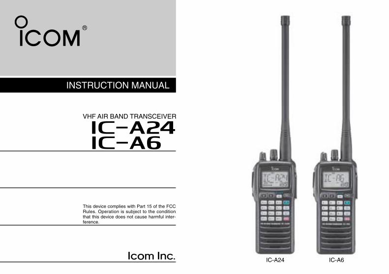
INSTRUCTION MANUAL iA6 iA24 VHF AIR BAND TRANSCEIVER This device complies with Part 15 of the FCC Rules. Operation is subject to the condition that this device does not cause harmful inter- ference. IC-A24 IC-A6
Transcript of IC-A24/A6 Instruction manual - Wings & Wheels
INSTRUCTION MANUAL
iA6iA24
VHF AIR BAND TRANSCEIVER
This device complies with Part 15 of the FCCRules. Operation is subject to the conditionthat this device does not cause harmful inter-ference.
IC-A24 IC-A6

i
SAFETY TRAINING INFORMATIONYour Icom radio generates RF electromagnetic energy duringtransmit mode. This radio is designed for and classified as“Occupational Use Only”, meaning it must be used only dur-ing the course of employment by individuals aware of the haz-ards, and the ways to minimize such hazards. This radio isNOT intended for use by the “General Population” in an un-controlled environment.
This radio has been evaluated for compliance at the distance of 2.5 cm withthe FCC RF exposure limits for “Occupational Use Only”. In addition, your Icomradio complies with the following Standards and Guidelines with regard to RFenergy and electromagnetic energy levels and evaluation of such levels for ex-posure to humans:
• FCC OET Bulletin 65 Edition 97-01 Supplement C, Evaluating Compliancewith FCC Guidelines for Human Exposure to Radio Frequency Electro-magnetic Fields.
• American National Standards Institute (C95.1-1992), IEEE Standard forSafety Levels with Respect to Human Exposure to Radio Frequency Elec-tromagnetic Fields, 3 kHz to 300 GHz.
• American National Standards Institute (C95.3-1992), IEEE RecommendedPractice for the Measurement of Potentially Hazardous ElectromagneticFields– RF and Microwave.
• The following accessories are authorized for use with this product. Use ofaccessories other than those specified may result in RF exposure levelsexceeding the FCC requirements for wireless RF exposure.; Belt Clip (MB-86/103), Rechargeable Ni-MH Battery Pack (BP-210N) and Alkaline Bat-tery Case (BP-208N).
To ensure that your expose to RF electromagnetic en-ergy is within the FCC allowable limits for occupationaluse, always adhere to the following guidelines:
W ARNING
• DO NOT operate the radio without a proper antenna attached, as this maydamaged the radio and may also cause you to exceed FCC RF exposurelimits. A proper antenna is the antenna supplied with this radio by the man-ufacturer or antenna specifically authorized by the manufacturer for usewith this radio.
• DO NOT transmit for more than 50% of total radio use time (“50% dutycycle”). Transmitting more than 50% of the time can cause FCC RF expo-sure compliance requirements to be exceeded. The radio is transmittingwhen “ ” appears on the function display. You can cause the radio totransmit by pressing the “PTT” switch.
• ALWAYS keep the antenna at least 2.5 cm (1 inch) away from the bodywhen transmitting and only use the Icom belt-clips which are listed onpage 31 when attaching the radio to your belt, etc., to ensure FCC RF ex-posure compliance requirements are not exceeded. To provide the recipi-ents of your transmission the best sound quality, hold the antenna at least5 cm (2 inches) from your mouth, and slightly off to one side.
The information listed above provides the user with the information needed tomake him or her aware of RF exposure, and what to do to assure that this radiooperates with the FCC RF exposure limits of this radio.
Electromagnetic Interference/CompatibilityDuring transmissions, your Icom radio generates RF energy that can possiblycause interference with other devices or systems. To avoid such interference,turn off the radio in areas where signs are posted to do so. DO NOT operatethe transmitter in areas that are sensitive to electromagnetic radiation such ashospitals and blasting sites.
Occupational/Controlled UseThe radio transmitter is used in situations in which persons are exposed asconsequence of their employment provided those persons are fully aware ofthe potential for exposure and can exercise control over their exposure.
CAUTION

ii
FOREWORD
Thank you for purchasing this Icom product. The IC-A24/A6VHF AIR BAND TRANSCEIVER is designed and built withIcom’s state of the art technology and craftsmanship. Withproper care this product should provide you with years oftrouble-free operation.
IMPORTANT
READ ALL INSTRUCTIONS carefully and completelybefore using the transceiver.
SAVE THIS INSTRUCTION MANUAL— This in-struction manual contains important operating instructions forthe IC-A24/A6.
EXPLICIT DEFINITIONS
SUPPLIED ACCESSORIES
Accessories included with the transceiver: Qty.q Antenna .......................................................................... 1w Belt clip ........................................................................... 1e Handstrap ....................................................................... 1r Battery pack* or battery case .......................................... 1t Wall charger* .................................................................. 1y Carrying case* ................................................................ 1u Headset adapter* ........................................................... 1
*The battery pack, wall charger, headset adapter or carrying casemay differ depending on version. Some versions do not include abattery pack, wall charger, headset adapter or carrying case.
WORD DEFINITION
RWARNING
CAUTION
NOTE
Personal injury, fire hazard or electric shock may occur.
If disregarded, inconvenience only. No risk of personal injury, fire or electric shock.
Equipment damage may occur.
q w e
t
r
y
u

iii
PRECAUTION
RWARNING! NEVER hold the transceiver so that theantenna is very close to, or touching exposed parts of thebody, especially the face or eyes, while transmitting. Thetransceiver will perform best if the microphone is 5 to 10 cmaway from the lips and the transceiver is vertical.
RWARNING! NEVER operate the transceiver with aheadset or other audio accessories at high volume levels.Hearing experts advise against continuous high volume op-eration. If you experience a ringing in your ears, reduce thevolume level or discontinue use.
NEVER connect the transceiver to an AC outlet or to apower source of more than 11.5 V DC. Such a connection willdamage the transceiver.
NEVER connect the transceiver to a power source that isDC fused at more than 5 A. Accidental reverse connection willbe protected by this fuse, higher fuse values will not give anyprotection against such accidents and the transceiver will beruined.
NEVER short the terminals of the battery pack. Also, cur-rent may flow into nearby metal objects, such as a necklace, etc. Therefore, be careful when carrying with, or placing nearmetal objects, carrying in handbags, etc.
DO NOT allow children to play with any radio equipmentcontaining a transmitter.
DO NOT operate the transceiver near unshielded electricalblasting caps or in an explosive atmosphere.
AVOID using or placing the transceiver in direct sunlight orin areas with temperatures below –10°C (+14°F) or above+60°C (+140°F).
The use of non-Icom battery packs/chargers may impairtransceiver performance and invalidate the warranty.
Even when the transceiver power is OFF, a slight current stillflows in the circuits. Remove the battery pack or case fromthe transceiver when not using it for a long time. Otherwise,the battery pack or installed dry cell batteries will become ex-hausted.
Icom, Icom Inc. and the logo are registered trademarks of Icom Incor-porated (Japan) in the United States, the United Kingdom, Germany, France,Spain, Russia and/or other countries.
FCC caution: Changes or modifications to this transceiver, notexpressly approved by Icom Inc., could void your authority tooperate this transceiver under FCC regulations. (U.S.A. only)

iv
SAFETY TRAINING INFORMATION ............................................... iFOREWORD ................................................................................... iiIMPORTANT .................................................................................... iiEXPLICIT DEFINITIONS ................................................................. iiSUPPLIED ACCESSORIES ............................................................ iiPRECAUTIONS............................................................................... iiiTABLE OF CONTENTS ................................................................. iv
1 PANEL DESCRIPTION ........................................................ 1–6Panel description ................................................................... 1Function display ..................................................................... 5
2 ACCESSORY ATTACHMENT .................................................. 7
3 BASIC OPERATION .......................................................... 8–11Setting a frequency ................................................................ 8Setting a squelch level ........................................................... 8Selecting a weather channel................................................... 8Receiving ............................................................................... 9Transmitting ........................................................................... 9ANL function ........................................................................... 9Low battery indicator ............................................................ 10Recall function ..................................................................... 10Setting weather alert function................................................ 11Accessing 121.5 MHz emergency frequency ....................... 11Lock function ........................................................................ 11Side tone function ................................................................ 11Setting beep tone ................................................................. 11Backlighting .......................................................................... 11
4 MEMORY OPERATION ................................................... 12–15Memory channel selection ................................................... 12Transferring memory contents ............................................. 12
Programming a memory channel ......................................... 13Memory names .................................................................... 14Clearing the memory contents ............................................. 14
5 SCAN OPERATION ......................................................... 16–17Scan types ........................................................................... 16COM band scan ................................................................... 16Memory scan ....................................................................... 16Weather channel scan (U.S.A. version only) ............................ 17 “TAG” channels ................................................................... 17
6 VOR NAVIGATION (IC-A24 only) .................................... 18–24VOR indications ................................................................... 18VOR functions ...................................................................... 19Flying to a VOR station ........................................................ 20Entering a desired course .................................................... 22Crosschecking position ........................................................ 22Duplex operation (U.S.A. version only) .................................... 24
7 BATTERY PACKS ........................................................... 25–27Battery charging ................................................................... 25Battery cautions ................................................................... 25Optional battery case ........................................................... 26Optional battery chargers ..................................................... 27
8 CLONING ................................................................................ 28
9 TROUBLESHOOTING ............................................................ 29
10 SPECIFICATIONS .................................................................. 30
11 OPTIONS ................................................................................ 31
12 QUICK REFERENCE ...................................................... 32– 33
13 OPTIONAL HEADSET CONNECTION .................................. 34
TABLE OF CONTENTS
1
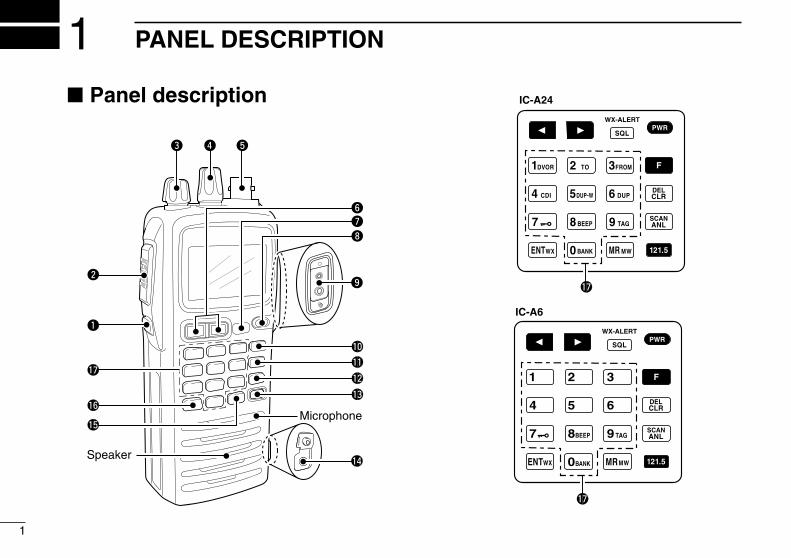
1 PANEL DESCRIPTION
Panel description
e r t
uy
i
o
Microphone
Speaker
!6
!5
!7
q
w
!1
!0
!2
!3
!4
WX-ALERT
IC-A24
!7
WX-ALERT
!7
IC-A6

2
1q BACKLIGHT SWITCH [LIGHT] (p. 11)Turns the backlight for display and keypad ON or OFF.
w PTT SWITCH [PTT] (p. 9)Push and hold to transmit; release to receive.• “ ” appears on the function display while transmitting.
e VOLUME [VOL] (p. 9)Adjusts the audio level.
r TUNING DIAL [DIAL] (pgs. 8–12)Rotate [DIAL] to select the desired frequency, WX chan-
nel number, BANK number and memory channel.Rotate [DIAL] to set the squelch level and beep tone
level.
t ANTENNA CONNECTOR [ANT] (p. 7)Connects the supplied antenna.
y RECALL CHANNEL UP/DOWN KEYS [ΩΩ]/[≈≈] (p. 10)Push to enter the recall function mode.Push to call the stored frequency in the recall
mode.Push , then push [Ω]/[≈]to replace stored re-
call frequencies to back or front.
u SQUELCH KEY [SQL•WX-ALERT] (p. 8)Push [SQL•WX-ALERT], then rotate [DIAL] to se-
lect the squelch level.• 24 squelch levels and squelch open (0) are available.
Push , then push [SQL•WX-ALERT] to turnthe WX-alert function ON or OFF.
i POWER SWITCH [PWR] (pgs. 9, 28)Push and hold for 2 sec. to turn the power ON
or OFF.While pushing and holding [MR•MW], push
[PWR] to enter the cloning function mode.
o EXTERNAL SPEAKER AND MICROPHONE JACKS[MIC/SP] (p. 34)Connects an OPC-499 HEADSET ADAPTER and headset, ifdesired.
!0 FUNCTION KEYPush to call up the function indicator, “ ”, thenpush another key to access its secondary function.• “ ” appears for 3 sec. after is pushed; at this timepushing again cancels the indication.
NOTE: In general, “ ” disappears when an-other key is pushed to activate a secondaryfunction. However, some keys which have morethan one secondary function, (such as [DUP]),do not cancel “ ”. In this case, “ ” disap-pears automatically after 3 sec.
1PANEL DESCRIPTION

3
1 PANEL DESCRIPTION
!1 CLEAR KEY [CLR•DEL] (pgs. 8–17) Push to turn to the frequency mode, when mem-
ory channel, WX channel, 121.5 MHz, squelchlevel setting or beep tone setting is selected.
Push , then push and hold [CLR•DEL] todelete a recall frequency data.
Push to clear the entered comment of memoryname while programming.
Push to stop the scan function to turn to the fre-quency mode while the scan function is operat-ing.
!2 ANL KEY [ANL•SCAN] (pgs. 9, 16, 17) Push to turn the ANL function ON or OFF. Push , then push [ANL•SCAN] to start the
scan function.
!3 EMERGENCY KEY [121.5 MHz] (p. 11)Push for 2 sec. to select the 121.5 MHz emergencyfrequency.
!4 DC POWER JACKConnect the AC adapter or optional cable to charge thebattery pack or to operate by external power supply. (seeright illustration)
!5 MEMORY MODE KEY [MR•MW] (pgs. 12–15) Push to call the memory channel mode.Push , then push [MR•MW] to program the
contents into the memory channels.
!6 ENTER KEY [ENT•WX] (pgs. 8, 14) Push to enter the numeral input. Enters con-
secutive zero digits. (p. 8)Push , then push [ENT•WX] to enter the
weather channel selection mode (U.S.A. versiononly). (p. 8)
Push to program the memory name. (p. 14)
NOTE: Some functions may not be available depending onversions. Ask your authorized dealer for details.
Wall charger
To [DC 11V]
IC-A24/A6 CP-20 (for 11 24 V)(optional)
To the cigarette lighter socket
• DC POWER CONNECTION

4
1PANEL DESCRIPTION
1!7 DIGIT KEYS Input the specified digit during frequency input, memory
channel selection, etc. In addition, each key has one or more secondary func-
tion after pushing as follows:
Push , then push [0•BANK] to select the mem-ory BANK number to rotate [DIAL] on the memoryoperation. (p. 12)
Push , then push [1•DVOR] to select the DVORdisplay from the CDI display in NAV band. (p. 19)*1
Push , then push [2•TO] to change thecourse indicator characteristics to “TO” flag inthe DVOR display in NAV band. (p. 19)*1
Corrects the deviation while using “TO” flag. *1
Push , then push [3•FROM] to change thecourse indicator characteristics to “FROM” flagin the DVOR display in NAV band. (p. 19)*1
Corrects the deviation while using “FROM” flag. *1
Push , then push [4•CDI] to select the CDI dis-play from the CDI display in NAV band. (p. 19)*1
Push , then push [5•DUP-W] to set the duplexfrequency in NAV band for U.S.A. version only.(p. 24)*1
Push , then push [6•DUP] to turn the duplexfunction ON and OFF in NAV band for U.S.A. ver-sion only. (p. 24)*1
Push , then push [7• ] to turn the key lockfunction ON and OFF. (p. 11)
Push , then push [8•BEEP] to turn the beeptone setting mode ON (p. 11).• Adjustable level; 0 to 9
Push , then push [9•TAG] to set the displayedmemory or weather channel as a “TAG” channel.(p. 17)
*1 These functions available on the IC-A24 only.

5
1 PANEL DESCRIPTION
Function display q FUNCTION INDICATOR (p. 2)
Appears when is pushed.
w TX INDICATOR (p. 9)Appears while transmitting.
e RX INDICATOR (p. 9)Appears when receiving a signal or when the squelchopens.
r DUPLEX INDICATOR (IC-A24 only) (p. 24)“DUP” appears when the duplex function is activated in
NAV mode.“DUP” blinks while setting the duplex frequency.
t LOW BATTERY INDICATOR (p. 10)Appears when the battery is nearing exhaustion. The at-
tached battery pack requires recharging.Appears and flashes when battery replacement is nec-
essary.
y LOCK INDICATOR (p. 11)Appears while the lock function is in use.
u FREQUENCY DISPLAY (pgs. 8, 14)Shows the operating frequency.Shows the channel name when the memory name func-
tion is selected.
i
q w e r t y
o
!0!1!1 !2!3
!4
u
!5

6
1PANEL DESCRIPTION
1
i TAG CHANNEL INDICATOR (p. 17)“ ” appears when the memory channel is set as a TAGchannel.
o MEMORY CHANNEL INDICATOR (pgs. 12–15)Shows the memory channel number.
!0 MEMORY BANK NUMBER INDICATOR (p. 12)Shows the selected memory bank number.
!1 OVERFLOW INDICATOR (IC-A24 only) (pgs. 18–22)Appears when the deviation between the desired courseand flying course is over 10 degrees.
!2 ANL INDICATOR (p. 9)Appears while the ANL (Automatic Noise Limiter) functionis in use.
!3 COURSE DEVIATION NEEDLES (IC-A24 only)(pgs. 18–22)Indicates the deviation between the desired course andyour actual flying course every 2 degrees.
!4 COURSE INDICATORS (IC-A24 only) (p. 19) Indicates where your aircraft is located on a VOR radial
in DVOR mode. Indicates where your desired course is located on a
VOR radial in CDI mode.
!5 TO-FROM INDICATOR (IC-A24 only) (p. 19)Indicates whether the VOR navigation information isbased on a course leading to the VOR station or leadingaway from the VOR station.

7
DAntennaCAUTION: DO NOT transmit without an antenna. Other-wise the transceiver may be damaged.
Insert the supplied antenna into the antenna connector andscrew down the antenna as shown below.
DBelt clipConveniently attaches to your belt.Attach the belt clip with the supplied screws as below.
NOTE: Use the supplied screws only.
DBattery pack replacementBefore replacing the battery pack, push [PWR] for 2 sec. toturn the power OFF.
Slide the battery release button forward, then pull the batterypack upward with the transceiver facing away from you.
Supplied screws
2 ACCESSORY ATTACHMENT

8
3BASIC OPERATION
Setting a frequencyïUsing keypadq Push [PWR] for 2 sec. to turn power ON, then push
[CLR•DEL] to select the frequency mode when memory CHnumber or WX CH number appears on the function dis-play.
w Push 5 appropriate digit keys to input the frequency.•Push [1]* as the 1st digit.• When a wrong digit is input, push [CLR•DEL] to clear,
then repeat step w again.• Push [ENT•WX] to enter consecutive zero digits.•Only [2]*, [5]*, [7• ] and [0•BANK] can be entered as the5th and final digit.
[EXAMPLE]• 111.225 MHz: Push• 117.250 MHz: Push• 120.000 MHz: Push• 125.300 MHz: Push
ïUsing the tuning dialq Push [PWR] for 2 sec. to turn power ON, then push
[CLR•DEL] to select the frequency mode when memory CHnumber or WX CH number appears on the function dis-play.
w Rotate [DIAL] to set the desired frequency.• To select the 1 MHz tuning step, push , then rotate
[DIAL]. Push again to return the normal tuning.
Setting a squelch levelThe transceiver has a noise squelch circuit to mute undesirednoise while receiving no signal.q Push [SQL•WX-ALERT], then rotate [DIAL] to select the
squelch level.• ‘SQL--0’ is loose squelch and ‘SQL--24’ is tight squelch.•Appears “ ” while the squelch is open.
w Push [SQL•WX-ALERT] or [CLR•DEL] to exit the squelchset mode.
Selecting a weather channel (U.S.A. version only)
The U.S.A. version has VHF marine WX (weather) channelreceiving capability for flightplanning.q Push , then push
[ENT•WX] to select WXchannel mode.• “WX--” and previously se-
lected channel number appears.w Rotate [DIAL] to select the desired WX channel.e Push [CLR•DEL] to exit the WX channel mode and return
to frequency mode.
23
9
3 BASIC OPERATION
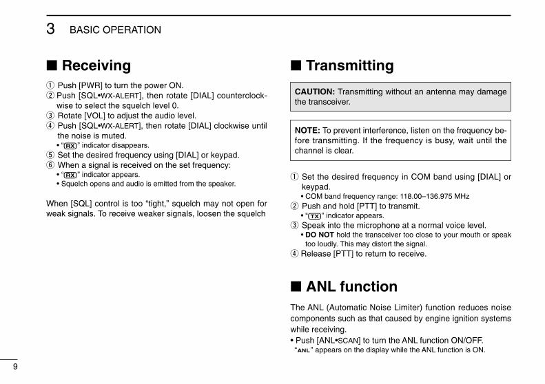
Receivingq Push [PWR] to turn the power ON.w Push [SQL•WX-ALERT], then rotate [DIAL] counterclock-
wise to select the squelch level 0.e Rotate [VOL] to adjust the audio level.r Push [SQL•WX-ALERT], then rotate [DIAL] clockwise until
the noise is muted.• “ ” indicator disappears.
t Set the desired frequency using [DIAL] or keypad.y When a signal is received on the set frequency:
• “ ” indicator appears.• Squelch opens and audio is emitted from the speaker.
When [SQL] control is too “tight,” squelch may not open forweak signals. To receive weaker signals, loosen the squelch
Transmitting
q Set the desired frequency in COM band using [DIAL] orkeypad.• COM band frequency range: 118.00–136.975 MHz
w Push and hold [PTT] to transmit.• “ ” indicator appears.
e Speak into the microphone at a normal voice level.• DO NOT hold the transceiver too close to your mouth or speak
too loudly. This may distort the signal.r Release [PTT] to return to receive.
ANL functionThe ANL (Automatic Noise Limiter) function reduces noisecomponents such as that caused by engine ignition systemswhile receiving.• Push [ANL•SCAN] to turn the ANL function ON/OFF.“ ” appears on the display while the ANL function is ON.
CAUTION: Transmitting without an antenna may damagethe transceiver.
NOTE: To prevent interference, listen on the frequency be-fore transmitting. If the frequency is busy, wait until thechannel is clear.

10
3BASIC OPERATION
Low battery indicatorLow battery indicator appearswhen the battery power has de-creased to a specified level. Theattached battery pack requiresrecharging.
Recall functionThe recall function stores the last 10 frequencies used.The function stores frequencies when the frequency is pro-grammed and transmitted on (except memory, weather andemergency channels).
DCalling the stored frequenciesPush to call the 1st stored frequency.Push to call the 10th stored frequency.
DDeletes the stored recall channelqPush or to select the deleting recall channel.wPush , then push [CLR•DEL] for 2 sec. to delete it.
• (e.g.) Deletes “r0” recall channel which is stored 120.450 MHz,and “r1” recall channel stores 123.450 MHz.
DReplaces the stored recall channelqPush or to select the replacing recall channel.wPush , then push or to replace it.
• Replaces the selected channel into the previous channel whenpush , then .
• Replaces the selected channel into the behind channel whenpush , then .
• (e.g.) Replaces “r0” which is stored 121.375 MHz into “r1”.
NOTE: Deletes in order of old recall channel automaticallywhen stored frequencies exceeds 10 channels.
Low battery indicator
Appears recall number.
: Push : Push
• Recall number rotation
3

11
3 BASIC OPERATION
Setting weather alert functionAn NOAA broadcast station transmits a weather alert tone be-fore any important weather announcements. When theweather alert function is turned ON, the transceiver detectsthe alert, and sounds a beep tone until the transceiver is op-erated. The previously selected (used) weather channel ischecked any time during standby, or while scanning.• Push , then push [SQL•WX-ALERT] to turns the weather
alert function ON (Indicates “ ”)/OFF (Indicates“ ”).
Accessing 121.5 MHzemergency frequency
The IC-A24 and IC-A6 can quickly gain access to the121.5 MHz emergency frequency. This function can be acti-vated even when the key lock function is in use.q Push [121.5] for 2 sec. to call the emergency frequency.w Push [CLR•DEL] to exit from the emergency frequency.
Lock functionThe lock function prevents accidental frequency changes andaccidental function activation.q Push , then push [7• ] to turn the lock function ON.
• “ ” appears.w To turn the function OFF, repeat step q above.
• “ ” disappears.
Side tone functionWhen using an optional headset, the transceiver outputs yourtransmitted voice to the headset for monitoring. Connect theoptional headset with the transceiver when using this function(OPC-499 HEADSET ADAPTER and headset are required).(p. 34)
DSetting the side tone levelq Push [PTT] to turn the transmit mode ON.w During transmit mode, rotate [DIAL] to adjust the monitor-
ing level.• ‘ST--0’ is OFF and ‘ST--10’ is Max. level.
NEVER operate the transceiver with a headset at high vol-ume levels for long period. A ringing in your ears mayoccur. If so, reduce the monitor level or discontinue use.
Setting beep toneThe beep tone which sounds at the push of a switch can beset, if desired.q Push , then push [8•BEEP] to enter the beep tone
setting mode.w Rotate [DIAL] to set the beep level.
• ‘BEP-- 0’ is OFF and ‘BEP-- 9’ is Max. level. e Push [CLR•DEL] to exit the beep tone set mode.
BacklightingPush [LIGHT] to turn the display and keypad backlighting ONor OFF.

12
4MEMORY OPERATION
Memory channel selectionThe transceiver has 200 memory channels for storage ofoften-used frequencies along with 6-character notes.
q Push [MR•MW] to select memory mode.• Memory BANK number and memory CH. number appears.
Using [DIAL]:w Push [0•BANK], then rotate [DIAL] to select the desired
memory BANK number, then push [0•BANK] (or[CLR•DEL]) to exit the BANK selection mode.• “BANK” appears.
e Rotate [DIAL] to select the desired memory CH. number.• If no memory CH. is programmed in the selected BANK, no
memory CH. selection is available.
Using the Keypad:w Push [0•BANK], then push appropriate digit key ([0•BANK]
to [9•TAG]) to select the desired memory BANK number,then push [0•BANK] (or [CLR•DEL]) to exit the BANK-se-lection mode.• “BANK” appears.
e Push 2 appropriate digit key (00 to 19) to select the de-sired memory CH. number.• If no memory CH. is programmed in the selected BANK, no
memory CH. selection is available.NOTE: Comments appear first when programmed, how-ever, the transceiver can be programmed by your dealer toshow the operating frequency first. Push [MR•MW] to dis-play the comment in this case.
Transferring memorycontents
This function transfers a memory channel’s contents into thefrequency mode. This is useful when searching for signalsaround a memory channel’s frequency.
q Push [MR•MW] to select memory mode.w Select the desired memory channel to be transferred using
[DIAL] or keypad.e Push , then push [MR•MW] to transfer the memory
channel’s contents into the frequency mode.• BANK number and memory CH. number disappears as
frequency mode is automatically selected and the mem-ory contents are transferred.
Memory mode Frequency mode
34

13
4 MEMORY OPERATION
Programming a memorychannel
The transceiver has 200 (20 CH. × 10 BANK) memory chan-nels for storage of often-used frequencies.
q Push [CLR•DEL] to select the frequency mode, if neces-sary.
w Select the desired frequency.• Push , then push [ENT•WX] to select a weather channel.*• Set the desired frequency or weather channel* using [DIAL] or
keypad.e Push , then push [MR•MW] to program the contents
into the selected memory channel.•Memory BANK and memory channel number appears.
r Rotate [DIAL] to select the desired memory channel num-ber.•Push , then push [0•BANK] to select the BANK number if de-sired.
• Push [CLR•DEL], [ENT•WX] or , then push [0•BANK] to exitthe BANK selection mode.
• “M,” BANK and memory numbers are blinks.t Push [ENT•WX] to program the information into the chan-
nel and return to the frequency mode.
*Weather channel: U.S.A. version only.
(or rotate [DIAL])
(or rotate [DIAL])
Push
PushPush
Push
Push
or
or
Push
Push
Push
or
•EXAMPLE: Programming WX-05* into memory BANK 3/memory channel 9.
14
4MEMORY OPERATION
Memory names
ïProgramming memory names
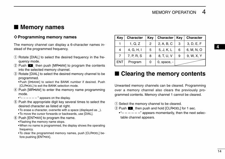
The memory channel can display a 6-character names in-stead of the programmed frequency.
q Rotate [DIAL] to select the desired frequency in the fre-quency mode.
w Push , then push [MR•MW] to program the contentsinto the selected memory channel.
e Rotate [DIAL] to select the desired memory channel to beprogrammed.•Push [0•BANK] to select the BANK number if desired. Push[CLR•DEL] to exit the BANK selection mode.
r Push [MR•MW] to enter the memory name programmingmode.• “-- -- -- -- -- -- ” appears on the display.
t Push the appropriate digit key several times to select thedesired character as listed at right.•To erase a character, overwrite with a space (displayed as _).•To move the cursor forwards or backwards, use [DIAL].
y Push [ENT•WX] to program the name.•Flashing the memory name stops.•When no name is programmed, the display shows the operatingfrequency.
•To clear the programmed memory names, push [CLR•DEL] be-fore pushing [ENT•WX].
Clearing the memory contents
Unwanted memory channels can be cleared. Programmingover a memory channel also clears the previously pro-grammed contents. Memory channel 1 cannot be cleared.
q Select the memory channel to be cleared.w Push , then push and hold [CLR•DEL] for 1 sec.
• “-- -- -- -- -- --” appears momentarily, then the next selec-table channel appears.
Key Character Key Character Key Character
1 1, Q, Z 2 2, A, B, C 3 3, D, E, F
4 4, G, H, I 5 5, J, K, L 6 6, M, N, O
7 7, P, R, S 8 8, T, U, V 9 9, W, X, Y
ENT Program 0 0, space, -
4

15
4 MEMORY OPERATION
Push
Push
Push PushPush
Push
Push Push
Push Push
•EXAMPLE: Programming 125.000 MHz into memory BANK 1/ memory channel 17 with “AIR-23” as a comment.
NOTE: Push [0•BANK], then rotate [DIAL] to select theBANK number, if desired. Push [CLR•DEL] to continuememory name programming.

16
5SCAN OPERATION
Scan typesThe U.S.A. version has 3 scan types to suit your needs. Thenon-U.S.A. versions have 2 scan types.
COM band scanq Push [CLR•DEL] to select the frequency mode.w Push [SQL•WX-ALERT] to set the squelch level to the point
where noise is just muted.e Push , then push [ANL•SCAN] to start the scan.
• When a signal is received, the scan pauses until it disappears.• To change the scanning direction, rotate [DIAL].
r To stop the scan, push [CLR•DEL].
Memory scanq Push [MR•MW] to select memory mode.w Push [SQL•WX-ALERT] to set the squelch level to the point
where noise is just muted.e Push , then push [ANL•SCAN] to start the scan.
• When a signal is received, the scan pauses until it disappears.• To change the scanning direction, rotate [DIAL].
r To stop the scan, push [CLR•DEL].
WEATHER CHANNEL SCANRepeatedly scans all “TAG” weather channels. Weatherchannels are available for the U.S.A. version only.
MEMORY SCANRepeatedly scans all“TAG” memory chan-nels. Used for checkingoften-used channelsand bypassing usuallybusy channels such ascontrol-tower frequen-cies.
COM BAND SCANRepeatedly scansall frequenciesover the entireCOM band.
108.00MHz
Scan
Jump
118.00MHz
136.975MHz
non-TAGchannel
non-TAG channel
Mch 2 Mch 4 Mch 6
Mch 7Mch 1
Mch 8Mch 10Mch 19
45

17
5 SCAN OPERATION
Weather channel scan (U.S.A. version only)
q Push , then push [ENT•WX] to select a weather chan-nel.
w Set squelch to the point where noise is just muted.e Push , then push [ANL•SCAN] to start the scan.
• When a signal is received, the scan pauses until it disappears.• To change the scanning direction, rotate [DIAL].
r To stop the scan, push [CLR•DEL].
“TAG” channel settingMemory and weather channels* can be specified to beskipped for the memory and weather channel* scans respec-tively. The “TAG” channel function is only available duringscan operation.
q Push [MR•MW] to select memory mode; or, push , thenpush [ENT•WX] to select a weather channel.*
w Select the desired memory channel to be a “TAG” chan-nel.
e Push , then push [9•TAG] to set a “TAG.”• “TAG” appears.• Non-“TAG” channels are skipped during scan.
r To cancel the “TAG” setting, repeat above steps.
*Weather channel: U.S.A. version only.
Memory channel 15 isscanned during memoryscan.
Memory channel 15 isskipped during scan.
Push then
Appears the “TAG” indicator.

18
6VOR NAVIGATION (IC-A24 ONLY)
VOR indicators
214
34
FROM
COM BAND(118.00 136.975 MHz)
NAV BAND (108.00 117.975 MHz)
DVOR MODE
Function display of the IC-A24General VOR equipment
To-from flag indicator
CDI MODE
Course indicator
Courseindicator
Course deviation needlesOverflow indicator
Push [F] then [4 CDI].Push [F] then [1 DVOR].
To-from flag indicator
Course indicator
Course deviation needle
To-from flag indicator
Two-degree deviation marks
56

19
6 VOR NAVIGATION (IC-A24 ONLY)
VOR functionsDTo select the CDI modeTo show the deviation between your flying course and the de-sired course, push , then push [4•CDI] to select the CDImode.
DTo select the DVOR modeWhen entering the NAV band, 108.000–117.975 MHz, theIC-A24 selects the DVOR mode automatically.
To show your aircraft’s direction to (or from) the VOR station,push , then push [1•DVOR] to select the DVOR mode.
D ‘TO’ or ‘FROM’ flag selectionThe to-from flag indicators indicate whether the VOR naviga-tion information is based on a course leading to the VOR sta-tion or leading away from the VOR station.
Push , then push [3•FROM] or [2•TO] to change the flagfrom ‘TO’ to ‘FROM’ or vice versa, respectively.
NOTE:•When using the ‘TO’ flag and passing through the VOR station,the ‘TO’ flag changes to the ‘FROM’ flag automatically.
•When turning power ON, the ‘FROM’ flag is selected automati-cally.
DSelecting the next VOR station when usingCDI mode (when using the course deviation needle)
q Push , then push [1•DVOR] to select the DVOR mode.w Push the keypad or rotate [DIAL] to set the next VOR sta-
tion’s frequency.e Push , then push [4•CDI] to select the CDI mode.
•Select ‘TO’ or ‘FROM’ flag, if desired.
Operating frequency can not be changed.
Each course deviation arrow indicates a two-degree deviation.
Course indicator is fixed, but it can be changed with the tuning dial or keypad.
Operating frequency can not be changed.
Course deviation needle does not appear.
Course indicator shows your direction to (or from) the VOR station.
20
6VOR NAVIGATION (IC-A24 ONLY)
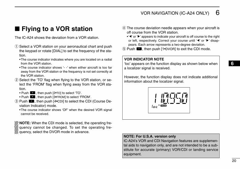
Flying to a VOR stationThe IC-A24 shows the deviation from a VOR station.
q Select a VOR station on your aeronautical chart and pushthe keypad or rotate [DIAL] to set the frequency of the sta-tion.•The course indicator indicates where you are located on a radialfrom the VOR station.
•The course indicator shows ‘- -’ when either aircraft is too faraway from the VOR station or the frequency is not set correctly atthe VOR station.
w Select the ‘TO’ flag when flying to the VOR station, or se-lect the ‘FROM’ flag when flying away from the VOR sta-tion.• Push , then push [2•TO] to select ‘TO’.• Push , then push [3•FROM] to select ‘FROM’.
e Push , then push [4•CDI] to select the CDI (Course De-viation Indicator) mode.•The course indicator shows ‘OF’ when the desired VOR signalcannot be received.
NOTE: When the CDI mode is selected, the operating fre-quency cannot be changed. To set the operating fre-quency, select the DVOR mode in advance.
r The course deviation needle appears when your aircraft isoff course from the VOR station.• ‘Ω’ or ‘≈’ appears to indicate your aircraft is off course to the rightor left, respectively. Correct your course until ‘Ω’ or ‘≈’ disap-pears. Each arrow represents a two-degree deviation.
t Push , then push [1•DVOR] to exit the CDI mode.
VOR INDICATOR NOTE‘loc’ appears on the function display as shown below whena localizer signal is received.
However, the function display does not indicate additionalinformation about the localizer signal.
NOTE: For U.S.A. version onlyIC-A24’s VOR and CDI Navigation features are supplemen-tal aids to navigation only, and are not intended to be a sub-stitute for accurate (primary) VOR/CDI or landing serviceequipment.
6

21
6 VOR NAVIGATION (IC-A24 ONLY)
VORstation
0
10 20
30
40
50
60
70
80
90
100 110
120 130 140 150 160 170
180 190
200
210
220
230
240
250
260
270 280
290 300
310 320 330 340 350 N
Magneticnorth
Desired course
Aircraft heading 40
123.65VORTACSEATTLE
116.8 Ch 115 SEA
THE AIRCRAFT IS ON COURSE
VORstation
0
10 20
30
40
50
60
70
80
90
100 110
120 130 140 150 160 170
180 190
200
210
220
230
240
250
260
270 280
290 300
310 320 330 340 350 N
Magneticnorth
Aircraft should be
heading 40
Aircraft heading 46
(6 off course)
Flown course
123.65VORTACSEATTLE
116.8 Ch 115 SEA
THE AIRCRAFT IS OFF COURSE
NOTE: The course deviation indica-tor appears when the aircraft is offcourse. In this example, the aircraft is6 degrees off course to the left. Thepilot must turn more than 6 degreesright to get back on course.

22
6VOR NAVIGATION (IC-A24 ONLY)
Entering a desired courseThe IC-A24 shows not only the deviation from the VOR sta-tion but the deviation from the desired course.
q Push the keypad or rotate [DIAL] to set the frequency forthe desired VOR station.•Push , then push [2•TO] or [3•FROM] to change the to-fromflag.
w Push , then push [4•CDI] to select CDI mode.e Set the desired course to the VOR station using the tun-
ing dial or keypad.• ‘Ω’ or ‘≈’ appears on the function display when your aircraft is offthe desired course.
•When your heading is correct, the ABSS function (see right col-umn for detail) may be useful instead of course input.
r The course deviation needle points to the right when youraircraft is off course to the left.•To get back on course, fly right more than the number of degreesindicated by the CDI arrows.
• If the overflow indicator appears on the right side, select a head-ing plus 10 degrees to the desired course; if the overflow indica-tor appears on the left side, select a heading minus 10 degrees.
Crosschecking positionq Select 2 VOR stations on your aeronautical chart.w Push the keypad or rotate [DIAL] to set the frequency of
one of the VOR station in the DVOR mode.•The course indicator shows course deviation from the VOR ra-dial. Note the radial you are on.
e Push the keypad or rotate [DIAL] to set the frequency ofthe other VOR station in DVOR mode.•Note the radial from the station you are on.
r Extend the radials from each VOR station on the chart.Your aircraft is located at the point where the lines inter-sect.
ABSS FUNCTIONIn the CDI mode, the Auto Bearing Set System (ABSS)adds or subtracts the number of degrees indicated by theCDI arrows from the Omni Bearing Selector (OBS).
To use ABSS, push , then push [2•TO] while using the‘TO’ flag; or, push , then push [3•FROM] while using the‘FROM’ flag.
q
w
Overflow indicator (left)
Overflow indicator (right)
Course deviation needles (left)e
r
Course deviation needles (right)
w e rq
6

23
6 VOR NAVIGATION (IC-A24 ONLY)
EXAMPLE: Entering the desired course bearing 65° to a VOR station.
VORstation
0
10 20
30
40
50
60
70
80
90
100 110
120 130 140 150 160 170
180 190
200
210
220
230
240
250
260
270 280
290 300
310 320 330 340 350
NMagneticnorth
VORstation
0
10 20
30
40
50
60
70
80
90
100 110
120 130 140 150 160 170
180 190
200
210
220
230
240
250
260
270 280
290 300
310 320 330 340 350 113.4 Ch 81 OLM
VORTACOLYMPIA
116.8 Ch 115 SEA
123.65VORTACSEATTLE
CROSSCHECKING POSITION

24
6VOR NAVIGATION (IC-A24 ONLY)
Duplex operation (U.S.A. version only)
The duplex function allows you to call a flight service stationwhile receiving a VOR station. The duplex function requiresfrequency programming for the flight service station in ad-vance.
DProgramming a duplex frequencyq Push [CLR•DEL] to select the frequency mode.w Set a NAV band frequency using the tuning dial or keypad.
•NAV band frequency range: 108.00–117.975 MHze Push , then push [5•DUP-W].
• “DUP” flashes and transmit frequency appears.r Set the frequency of the flight service station using the tun-
ing dial or keypad. When using the tuning dial, push[ENT•WX] after setting a frequency.•The displayed frequency returns to the NAV band frequency.
DOperating the duplex functionq Set the desired frequency in NAV band.
•NAV band frequency range: 108.00–117.975 MHzw Push , then push [6•DUP] to turn the duplex function
ON.• “DUP” appears on the function display.
e Push and hold [PTT] to transmit at the pre-programmedtransmit frequency.
r Release [PTT] to return to receive.t Push , then push [6•DUP] to cancel the function.
• “DUP” disappears on the function display.
NOTE: A duplex frequency can be programmed into eachmemory channel independently. Set a duplex frequencybefore programming the memory channel, if desired. Theduplex ON/OFF setting can also be programmed into amemory channel.
EXAMPLE: Programming 123.65 MHz as the transmit frequency in the duplex function.
6

25
7 BATTERY PACKS
Battery chargingPrior to using the transceiver for the first time, the batterypack must be fully charged for optimum life and operation.
CAUTION: To avoid damage to the transceiver, turn thepower OFF while charging.
• Recommended temperature range for charging: +10°C to +40°C (+50°F to +104°F)- The Li-Ion battery (optional) is functioning within –20°C to
+60°C (–4°F to +140°F)• Use the supplied AC adapter on regular charging. NEVER
use another manufacture’s adapters.• Use the specified chargers (BC-119N, BC-121N and
BC-144N). NEVER use another manufacture’s charger.
NEVER connect DC power to the transceiver when in-stalling Alkaline batteries. Such a connection will damagethe transceiver.
D Recycling information (U.S.A. only)The product that you have purchased contains arechargeable battery. The battery is recyclable.At the end of its life, under various state andlocal laws, it may be illegal to dispose of this bat-tery into the municipal waste stream. Call 1-800-822-8837 for battery recycling options in yourarea or contact your dealer.
Battery cautionsCAUTION! NEVER insert battery pack/transceiver(with the battery pack attached) with wet or soiled into thecharger. This may result in corrosion of the charger terminalsor damage to the charger. The charger is not waterproof andwater can easily get into it.
NEVER incinerate used battery packs. Internal battery gasmay cause an explosion.
NEVER immerse battery pack in water. If the battery packbecomes wet, be sure to wipe it dry immediately (particularlythe battery terminals BEFORE attaching it to the transceiver.
NEVER short the terminals of the battery pack. Also, cur-rent may flow into nearby metal objects, such as a necklace,etc. Therefore, be careful when carrying with, or placing nearmetal objects, carrying in handbags, etc.
If your battery pack seem to have no capacity even afterbeing charged, completely discharge them by leaving thepower ON overnight. Then, fully charge the battery packagain. If the batteries still do not retain a charge (or very little),new battery pack must be purchased.
Turn the transceiver power OFF when charging the batterypack. Otherwise, the battery pack may not fully charge orcharge properly.

26
7BATTERY PACKS
DRegular chargingq Attach the battery pack to the transceiver.w Be sure to turn the transceiver power OFF.e Connect the Wall charger or optional cable (CP-20) as
shown below.r Charging the battery pack approx. 8 hours, depending on
the remaining power condition.
DO NOT charge BP-210N more than 12 hours. Otherwise,BP-210N will be damaged. BP-210N must be charged for8–12 hours only.
Optional battery caseWhen using a battery case attached to the transceiver, install6 × AA(R6) size Alkaline batteries as illustrated below.
qRemove the battery case from the transceiver.w Install 6 × AA(R6) size Alkaline batteries.
•Be sure to observe the correct polarity.
CAUTION:•When installing batteries, make sure they are all the samebrand, type and capacity. Also, do not mix new and oldbatteries together.
•Keep battery contacts clean. It’s a good idea to clean bat-tery terminals once a week.
Wall charger
To [DC 11V]
IC-A24/A6 with attached battery pack
CP-20 (for 11 24 V)(optional)
To the cigarette lighter socket
Turn power OFF
7

27
7 BATTERY PACKS
Optional battery chargersDRapid charging with the BC-119N+AD-101The optional BC-119N provides rapid charging of batterypacks. The following are additionally required.• AD-101 charger adapter.• An AC adapter (may be supplied with BC-119N depending on ver-
sions).NOTE: Attach the spacer (Spacer B/C) to the adapter (Spacer
A) with orientation as illustrated below.
DRapid charging with the BC-121N+AD-101The optional BC-121N allows up to 6 battery packs to becharged simultaneously. The following are additionally re-quired.• Six AD-101 charger adapters.• An AC adapter (BC-124) or the DC power cable (OPC-656).
NOTE: Attach the spacer (Spacer B/C) to the adapter (SpacerA) with orientation as illustrated below.
AD-99 (suppliedwith AD-101)
AD-101(optional)
AC adapter
Supplied screwswith AD-101.
BC-119N(optional)
IC-A24/A6
BP-209N/BP-210N/BP-211N
Turn power OFF
Spacer A
Spacer B/C
Check orientation
andIC-A24/A6
BP-209N/BP-210N/BP-211N
AC adapter (BC-124: Purchase separately)
AD-101 charger adapters are installed in each slot.
DC power cable (OPC-656)(Connect with the DC power supply; 13.8 V/at least 7 A)
Turn power OFF
AD-99 (supplied with AD-101)
Spacer A
Spacer B/C
Check orientation
and

28
8CLONING
Cloning allows you to quickly and easily transfer theprogrammed data from one transceiver to anothertransceiver, or, data from PC to a transceiver using theoptional CS-A24 cloning software.
DTransceiver to transceiver cloningq Connect the OPC-474 CLONING CABLE with adapter plugs
to [SP/MIC] jack of the master and slave transceivers.• The master transceiver is used to send data to the slave trans-
ceiver.w While push and holding [MR•MW],
push [PWR] to enter cloning mode(for operating the master transceiveronly).• “CLONE” appears and the transceiversenter the clone standby condition.
e Push [MR•MW] on the master trans-ceiver.• “CL-OUT” appears in the master trans-ceiver’s display.
• “COURSE DEVIATION NEEDLES”shows that cloning is taking place
• “CL-IN” appears automatically in theslave transceiver’s display.
r When cloning is finished, turn power OFF, then ON againto exit cloning mode.
NOTE: DO NOT transfer the data from IC-A24 to IC-A6,when the data contains the NAV band data. In such case,cloning error may occur.
DCloning using PCData can be cloned to and from a PC (Microsoft®, Windows®
98/98SE/Me/2000/XP) using the optional CS-A24 CLONINGSOFTWARE and the optional OPC-478 (RS-232C type) orOPC-478U (USB type) CLONING CABLE. Consult the CS-A24CLONING SOFTWARE HELP file for details.
DCloning errorNOTE: DO NOT push [ENT•WX] on the slave transceiverduring cloning. This will cause acloning error.
When the display at right appears, acloning error has occurred.
In this case, both transceivers automatically return to theclone standby condition and cloning must be repeated.
Microsoft and Windows are registered trademarks of Mi-crosoft Corporation in the U.S.A. and other countries.
78
“COURSE DEVIATIONNEEDLES” shows thatcloning is taking place.
29
9 TROUBLESHOOTING
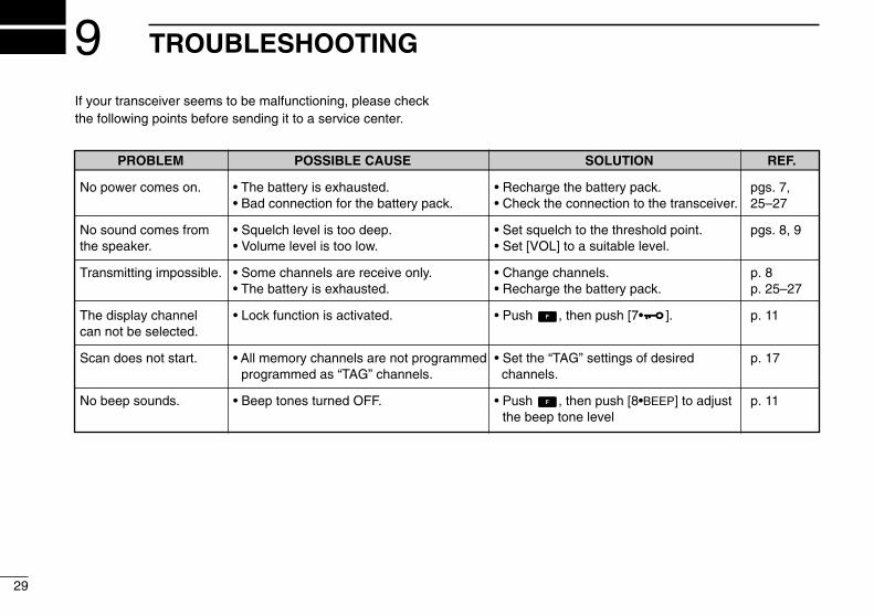
If your transceiver seems to be malfunctioning, please checkthe following points before sending it to a service center.
PROBLEM POSSIBLE CAUSE SOLUTION REF.
No power comes on. • The battery is exhausted. • Recharge the battery pack. pgs. 7,• Bad connection for the battery pack. • Check the connection to the transceiver. 25–27
No sound comes from • Squelch level is too deep. • Set squelch to the threshold point. pgs. 8, 9the speaker. • Volume level is too low. • Set [VOL] to a suitable level.
Transmitting impossible. • Some channels are receive only. • Change channels. p. 8• The battery is exhausted. • Recharge the battery pack. p. 25–27
The display channel • Lock function is activated. • Push , then push [7• ]. p. 11can not be selected.
Scan does not start. • All memory channels are not programmed • Set the “TAG” settings of desired p. 17programmed as “TAG” channels. channels.
No beep sounds. • Beep tones turned OFF. • Push , then push [8•BEEP] to adjust p. 11the beep tone level

30
10SPECIFICATIONS
DGeneral•Frequency coverage (MHz): TX 118.000 to 136.975
RX 108.000 to 136.975*1
WX 161.650 to 163.275*2
*1: IC-A24 only, IC-A6; 118.000 to 136.975 MHz*2:U.S.A. version only.• Mode : 6K00A3E
16K0G3E (161.65 to 163.275 MHz)•Channel spacing : 25 kHz•Number of memory channels : 200 (20 CH. × 10 BANK)•Power supply requirement : Specified battery packs/case or
11.0 V DC at external DC jack•Usable temp. range : –10˚C to +60˚C (+14°F to +140°F)•Current drain :
Tx 1.5 A typicalRx 70 mA typical (at stand by)
300 mA typical.(at AF max.)•Antenna connector : BNC 50 Ω (nominal)•Dimensions : 54(W)×129.3(H)×35.5(D) mm(projections not incl.) 21⁄8(W) × 53⁄32(H) × 113⁄32(D) inch
•Weight : Approx. 180 g (6.35 oz)(Without the battery pack and antenna.)
DTransmitter•Output power : 5 W (PEP) typical
1.5 W (CW) typical•Modulation : Low level modulation•Modulation limiting : 70 to 100%•Audio harmonic distortion : Less than 10% (at60 % mod.)•Hum and noise ratio : More than 35 dB•Spurious emissions : More than 46 dB (except oper-
ating frequency ±6.25 Hz range)•Microphone connector : 3-conductor 2.5(d) mm (1/10˝)/
more than 100 kΩ
DReceiver•Receive system : Double conversion
superheterodyne• Intermediate frequencies : 1st 30.05 MHz
2nd 450 kHz•Sensitivity VOR (AM 6dB S/N): Less than –3 dBµ typical
COM (AM 6dB S/N): Less than –6 dBµ typicalWX (FM 12dB SINAD): Less than –13 dBµ typical
•Squelch sensitivity : AM Less than 0 dBµFM Less than –7 dBµ
•Selectivity : More than 7.5 kHz/–6 dB)Less than 25 kHz/–60 dB)
•Spurious response : AM More than 60 dBrejection FM More than 30 dB
•Audio output power : More than 500 mW typical(at 10% distortion with an 8 Ωload, 30% mod.)
•Noise and hum : More than 40 dB at 30% mod.•External SP connector : 3-conductor 3.5 (d) mm
(1/8˝)/8 ΩAll stated specifications are subject to change withoutnotice or obligation.
910

31
11 OPTIONS
D BATTERY CASE AND PACKS•BP-208N BATTERY CASE
Battery case for 6 × AA (R6) Alkaline cells.• BP-209N Ni-Cd BATTERY PACK
7.2 V/1100 mAh Ni-Cd battery pack.• BP-210N Ni-MH BATTERY PACK
7.2 V/1650 mAh Ni-MH battery pack.• BP-211N Li-Ion BATTERY PACK
7.4 V/1800 mAh Li-Ion battery pack.
D CHARGERS• BC-110AR/DR WALL CHARGER
The same as supplied with the transceiver.•BC-119N DESKTOP CHARGER + AD-101 CHARGER ADAPTER
+ BC-145 AC ADAPTER
For rapid charging of battery packs. An AC adapter is supplied withthe charger depending on versions. Charging time: approx. 1.5 to 2hours.
•BC-121N MULTI-CHARGER + AD-101 CHARGER ADAPTER (6 pcs.)+ BC-124 AC ADAPTER
For rapid charging of up to 6 battery packs (six AD-101’s are re-quired) simultaneously. An AC adapter should be purchased sepa-rately. Charging time: approx. 1.5 to 2 hours.
•BC-144N DESKTOP CHARGER
For rapid charging of BP-209N (Ni-Cd) and BP-210N (Ni-MH).
D BELT CLIPS• MB-103 BELT CLIP
The same as supplied with the transceiver.• MB-86 SWIVEL BELT CLIP
Belt clip for swivel type.• MB-96F/96N LEATHER BELT HANGER
MB-96F: Attaches with the supplied belt clip (Fixed type).MB-96N: Belt hanger for swivel type.
D DC CABLES•CP-20 CIGARETTE LIGHTER CABLE
Charges the battery pack through a cigarette lighter socket*.Operates IC-A24/A6 through a cigarette lighter socket*.
*Both 12 V and 24 V batteries are available.•OPC-656 DC POWER CABLE FOR BC-121N WITH DC
Charges the battery pack using 13.8 V power source instead of theAC adapter for BC-121N.
D OTHER OPTIONS• OPC-499 HEADSET ADAPTER CABLE
When using an optional headset, such as those from the DavidClark Co. via the adapter, the transceiver outputs your transmittedvoice to the headset for monitoring.
• LC-159 CARRYING CASE
Helps protect the transceiver from scratches, etc.
Different versions of this radio use different options. Askyour authorized dealer for details.

OP
ER
ATIO
N G
UID
E
iA
24
/A
6
n V
OR
NA
VIG
AT
ION
(p.
20)
n V
OR
NA
VIG
ATI
ON
(p. 2
2)
F
lyin
g t
o a
VO
R s
tati
on
En
teri
ng
a d
esir
ed c
ou
rse.
q w e
q w
Pus
h ke
ypad
or
rota
te [
DIA
L] t
o se
t th
e fr
eque
ncy
for
the
de-
sire
d V
OR
sta
tion.
Pus
h
,
then
pus
h [2
TO
] o
r [3
FR
OM
] to
chan
ge th
e to
- f
rom
flag
.
Pus
h
,
the
n pu
sh [
4 C
DI]
to
sele
ct C
DI m
ode.
'Ω
' or
' ≈' a
ppea
rs o
n th
e fu
nc-
tio
n di
spla
y w
hen
your
airc
raft
is
off t
he d
esire
d co
urse
. W
hen
your
hea
ding
is c
orre
ct,
the
AB
SS
fun
ctio
n m
ay b
e u
sefu
l ins
tead
of c
ours
e in
put.
Sel
ect
a V
OR
sta
tion
on y
our
aero
-na
utic
al c
hart
and
pus
h th
e ke
ypad
or
rot
ate
[DIA
L] t
o se
t th
e st
atio
n's
freq
uenc
y.
Sel
ect
the
'TO
' fla
g w
hen
flyin
g to
th
e V
OR
st
atio
n,
or
sele
ct
the
'FR
OM
' fla
g w
hen
flyin
g aw
ay f
rom
th
e V
OR
sta
tion.
P
ush
, th
en p
ush
[2 T
O] t
o se
- l
ect '
TO
'. P
ush
, th
en p
ush
[3 F
RO
M] t
o s
e lec
t 'F
RO
M'.
Pus
h
,
then
pus
h [4
C
DI]
to s
e-le
ct th
e C
DI m
ode.
The
cou
rse
indi
cato
r s
how
s 'O
F'
whe
n th
e de
sire
d V
OR
sig
nal c
an n
ot b
e re
ceiv
ed.
The
cou
rse
devi
atio
n ne
edle
ap-
pear
s w
hen
your
ai
rcra
ft
is
off
cour
se fr
om th
e V
OR
sta
tion.
Pus
h
,
the
n pu
sh [
1 D
VO
R]
to
exit
the
CD
I mod
e.
r t
VO
R N
AV
IGA
TIO
N F
lyin
g to
a V
OR
sta
tion
(Con
tinue
d)
n S
CA
N (
pgs.
16,
17)
q w e
Pus
h [C
LR D
EL]
, [M
R M
W]
or
,
then
[E
NT
WX
]* t
o se
lect
the
fre
-qu
ency
, mem
ory
or W
X C
H*
mod
e.
Pus
h
,
then
pus
h [A
NL
SC
AN
] to
sta
rt s
cann
ing.
D
ecim
al p
oint
blin
ks d
urin
g sc
an-
ning
. R
otat
e [D
IAL]
to c
hang
e th
e sc
an-
ning
dire
ctio
n.
Pus
h [C
LR D
EL]
to
canc
el t
he s
can-
ning
.
32
12QUICK REFERENCE
Important operating instructions are summed up in this and the following pagefor your simple reference.By cutting along the line and folding on the dotted line, it will become a cardsized operating guide which can easily be carried in a card case or wallet,etc.
q Cut w Fold e Complete
<C
UT
HE
RE
>

33
12 QUICK REFERENCE
Transferrin
g m
emo
ry con
tents
n M
EM
OR
Y O
PE
RA
TION
(p. 13) n
ME
MO
RY
OP
ER
ATIO
N (p. 12)
q wert
Push [C
LR D
EL] to select the fre-
quency mode or push , then
push [EN
T W
X] to select WX
CH
* m
ode.
Select the desired frequency or W
X
CH
.*
Push , then push [M
R M
W] to
enter mem
ory programm
ing mode.
“M”, B
AN
K and m
emory num
bers blink on the display.
Rotate [D
IAL] (or push keypad) to
select a desired mem
ory CH
num-
ber (0 to 19). P
ush [0 B
AN
K], then select the B
AN
K
number
if desired.
Push
[0 BA
NK] to exit the B
AN
K selec-
tion mode.
Push
[EN
T
WX]
to program
the
mem
ory contents.
qwe
Push [M
R
MW
] to enter mem
ory m
ode.
Select the desired channel to be
transferred.
Push , then push [M
R M
W].
BA
NK
number and m
emory C
H
number disappears as frequency
mode
is autom
atically selected
and the
mem
ory contents
are transferred.
n M
EM
OR
Y O
PE
RA
TIO
N (p. 12)
n TA
G C
HA
NN
EL
S (p. 17)
q w
Push [M
R M
W] to select the m
em-
ory mode.
Push , then [9 TA
G] to turn the
channel “TAG
” ON
and OF
F.
n L
OC
K F
UN
CT
ION
(p. 9)
Push ,T
hen push [7 ] to turn the key lock function O
N.
“ ” appears on the display.
Push ,T
hen push [7 ] to turn the keylock function O
FF.
q w
Mem
ory p
rog
ramm
ing
*WX
CH
available U.S
.A. version only.
Mem
ory B
AN
K/C
H selectio
n
Push [M
R•M
W] to enter the m
em-
ory CH
mode.
Push , then push [0 B
AN
K] to enter the B
AN
K selection m
ode.
Push keypad (or rotate [D
IAL]) to
select the desired BA
NK
number
(BA
NK
0 to 9).
Push , then push [0 B
AN
K] (or push [E
NT
WX]) to set the B
AN
K
number and exit the B
AN
K selec-
tion mode.
Push [C
LR D
EL] to exit the B
AN
K
selection mode.
qwe

34
13OPTIONAL HEADSET CONNECTION
DOPC-499 (HEADSET ADAPTER) connectionWhen using a headset, such as those from the David Clark Co. via the OPC-499 HEADSET ADAPTOR adapter, the transceiver out-puts your transmitted voice to the headset for monitoring. See “ Side tone function “(p. 11) when setting the side tone level.
PTT
OPC-499
IC-A24/A6
PTT switch
HEADSET(Must be purchasedseparately)
Use a PTT switch with a 3.5 mm (1/8") diameter plug, if required.
1213

1-1-32 Kamiminami, Hirano-ku, Osaka 547-0003, Japan
A-6403D-1EXPrinted in Japan© 2004 Icom Inc.