IC-A120/IC-A120E FULL MANUAL - Icom · FULL MANUAL INDEX 10 CI-V INFORMATION ... Displays “CH...
41
FULL MANUAL INDEX 10 CI-V INFORMATION 9 SPECIFICATIONS AND OPTIONS 8 CONNECTION AND INSTALLATION 7 MENU MODE 6 Bluetooth ® OPERATION 5 OTHER FUNCTIONS 4 MEMORY OPERATION 3 SCAN OPERATION 2 BASIC OPERATION 1 PANEL DESCRIPTION INTRODUCTION iA120 iA120E VHF AIR BAND TRANSCEIVER
Transcript of IC-A120/IC-A120E FULL MANUAL - Icom · FULL MANUAL INDEX 10 CI-V INFORMATION ... Displays “CH...
FULL MANUAL
INDEX
10 CI-V INFORMATION
9 SPECIFICATIONS AND OPTIONS
8 CONNECTION AND INSTALLATION
7 MENU MODE
6 Bluetooth® OPERATION
5 OTHER FUNCTIONS
4 MEMORY OPERATION
3 SCAN OPERATION
2 BASIC OPERATION
1 PANEL DESCRIPTION
INTRODUCTION
iA120iA120E
VHF AIR BAND TRANSCEIVER

i
INTRODUCTION
FOREWORDREAD ALL INSTRUCTIONS carefully before using the IC-A120/IC-A120E vhf air band transceiver.KEEP THIS FULL MANUAL, because it contains important operating information that may be useful in the future.The BASIC MANUAL is supplied with the transceiver.
Icom, Icom Inc. and the Icom logo are registered trademarksof Icom Incorporated (Japan) in Japan, the United States,the United Kingdom, Germany, France, Spain, Russia,Australia, New Zealand and/or other countries.

1-1
Section 1 PANEL DESCRIPTIONFront panel .............................................................................1-2Function display ....................................................................1-3

1 PANEL DESCRIPTION
1-2
Front panel
q VOLUME CONTROL KNOB Adjusts the audio output level.w STATUS INDICATOR ➥ Lights red while transmitting. ➥ Lights green while receiving.e UP/DOWN KEYS [∫]/[√] Push to select an operating channel, frequency,
and menu items.r POWER KEY [ ] ➥ Hold down for 1 second to turn the power ON or
OFF. ➥ Push to exit the Menu mode.t ENTER/MHz/GRP KEY [ ]/[MHz]/[GRP] ➥ Push to save entered data, a selected item, and
so on in the Menu mode. ➥ Push to open the “MEMORY” menu in the
Memory mode. ➥ Push to enter the MHz digit Selection mode in
the VFO mode*. * For only EXP, USA, and EUR versions.
y MENU/CLEAR KEY [MENU]/[CLR] ➥ Push to enter the Menu mode. ➥ Push to cancel entered data, or to return to the
previous screen in the Menu mode.u SQUELCH ADJUSTMENT/LOCK KEY [SQL]/[ ] ➥ Push to open the squelch adjustment window (p. 2-3). ➥ Hold down for 1 second to turn the Key Lock
function ON or OFF (p. 7-6).i PRIORITY CHANNEL/DUALWATCH KEY [PRI]/[DUAL] ➥ Push to select the Priority channel. ➥ Hold down for 1 second to turn ON Dualwatch
operation, push to turn it OFF.o SCAN KEY [SCAN] ➥ Push to start or stop a scan. ➥ Hold down for 5 seconds to select whether or not
to lockout the displayed channel (p. 7-3).!0 MICROPHONE CONNECTOR Connect the supplied or an optional microphone.
q e
!0
SPEAKERFUNCTION DISPLAYw r
tyuio
1 PANEL DESCRIPTION
1-3
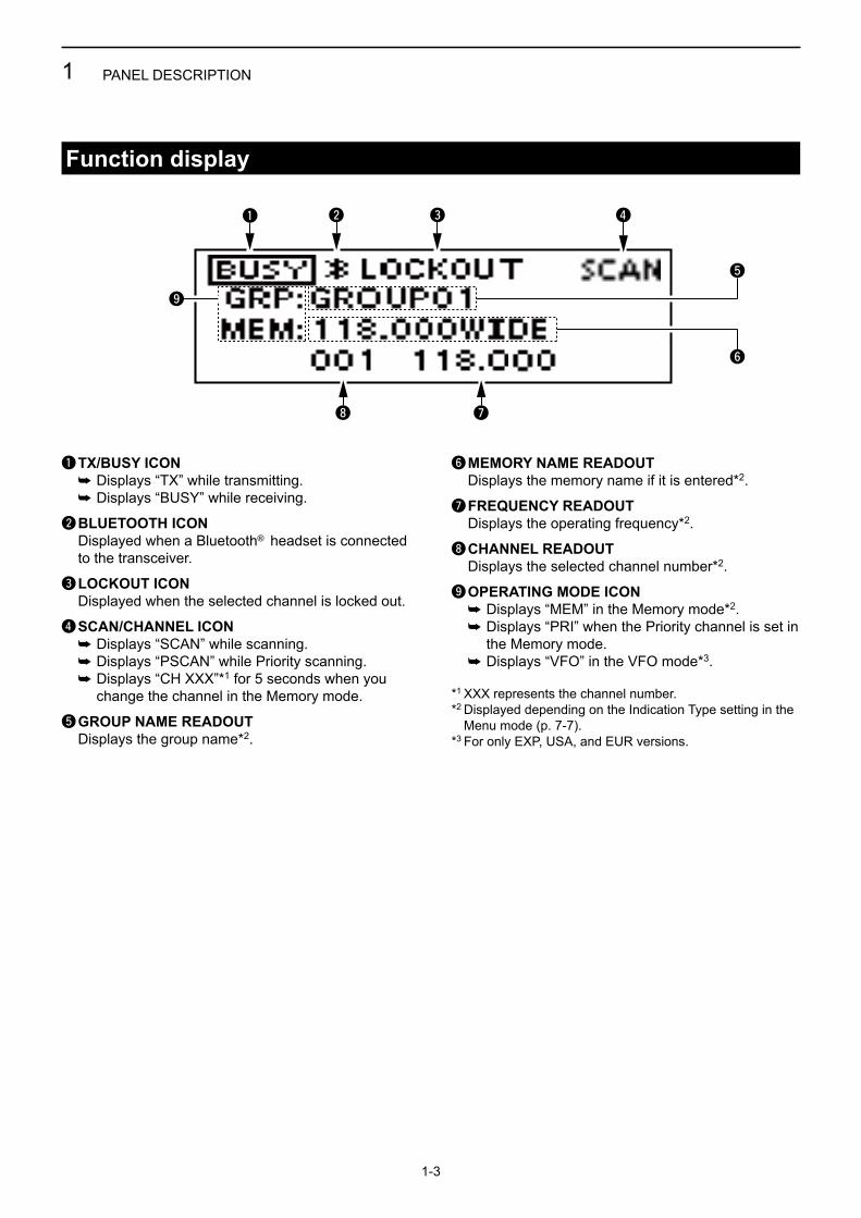
Function display
q TX/BUSY ICON ➥ Displays “TX” while transmitting. ➥ Displays “BUSY” while receiving.
w BLUETOOTH ICON Displayed when a Bluetooth® headset is connected
to the transceiver.
e LOCKOUT ICON Displayed when the selected channel is locked out.
r SCAN/CHANNEL ICON ➥ Displays “SCAN” while scanning. ➥ Displays “PSCAN” while Priority scanning. ➥ Displays “CH XXX”*1 for 5 seconds when you
change the channel in the Memory mode.
t GROUP NAME READOUT Displays the group name*2.
y MEMORY NAME READOUT Displays the memory name if it is entered*2.
u FREQUENCY READOUT Displays the operating frequency*2.
i CHANNEL READOUT Displays the selected channel number*2.
o OPERATING MODE ICON ➥ Displays “MEM” in the Memory mode*2. ➥ Displays “PRI” when the Priority channel is set in
the Memory mode. ➥ Displays “VFO” in the VFO mode*3.
*1 XXX represents the channel number.*2 Displayed depending on the Indication Type setting in the
Menu mode (p. 7-7).*3 For only EXP, USA, and EUR versions.
RX
q w e r
i u
t
y
o
2-1
Section 2 BASIC OPERATIONTurning ON the transceiver ..................................................2-2
D Entering the password .....................................................................2-2
Receiving and transmitting ..................................................2-2Adjusting the squelch ...........................................................2-3

2 BASIC OPERATION
2-2
Turning ON the transceiverHold down [ ] for 1 second to turn ON the power. If the transceiver is preset for a start-up password, enter the 6 digits password.
While in the Password Entry mode, “PASSWORD” is displayed.
D Entering the passwordEnter the password in the following manner.
KEY
NUMBER0
5
1
6
2
7
3
8
4
9
Example:If the password is 513824, push [SCAN], [PRI/DUAL], [MENU/CLR], [MENU/CLR], [SQL/ ], and then push[ /MHz/GRP].• Note that each key represents 2 digits. That means,
“123456” and “678901” are entered in exactly the same way (requires no multiple or extended pushing.)
• The entered password will not be displayed.• If “PASSWORD” does not disappear after entering, the
entered password is incorrect. Turn OFF the transceiver, and then try again.
Receiving and transmitting1. Setting the frequency
Setting the frequency in the Memory mode1) Open the “MEMORY” menu. ➥ Push [ /MHz/GRP]. 2) Select “GROUPS” item. ➥ Push [∫] or [√], and then push [ /MHz/GRP].
3) Select a desired group. ➥ Push [∫] or [√], and then push [ /MHz/GRP].
4) Select a desired channel. ➥ Push [∫] or [√].
Setting the frequency in the VFO mode(For only EXP, USA, and EUR versions.)1) Switch the transceiver to the VFO mode. ➥ Select “VFO MODE” group in the Menu mode
and then push [ /MHz/GRP].
MENU > VFO MODE/MEMORY MODE
2) Set the MHz digit. ➥ Push [ /MHz/GRP], and then push [∫] or [√]. • The MHz digit blinks.3) Exit the MHz digit Selection mode. ➥ Push [ /MHz/GRP] again.4) Set the kHz digit. ➥ Push [∫] or [√].
TIP: You can select the channel spacing in the “CH SPACING” item*.
* The menu may not be displayed, depending on the transceiver’s presettings. Ask your authorized Icom dealer or transceiver administrator for details.
CAUTION: In Canada, use of 8.33 kHz Channel Spacing of this radio is strictly prohibited and shall not be used.
2 BASIC OPERATION
2-3
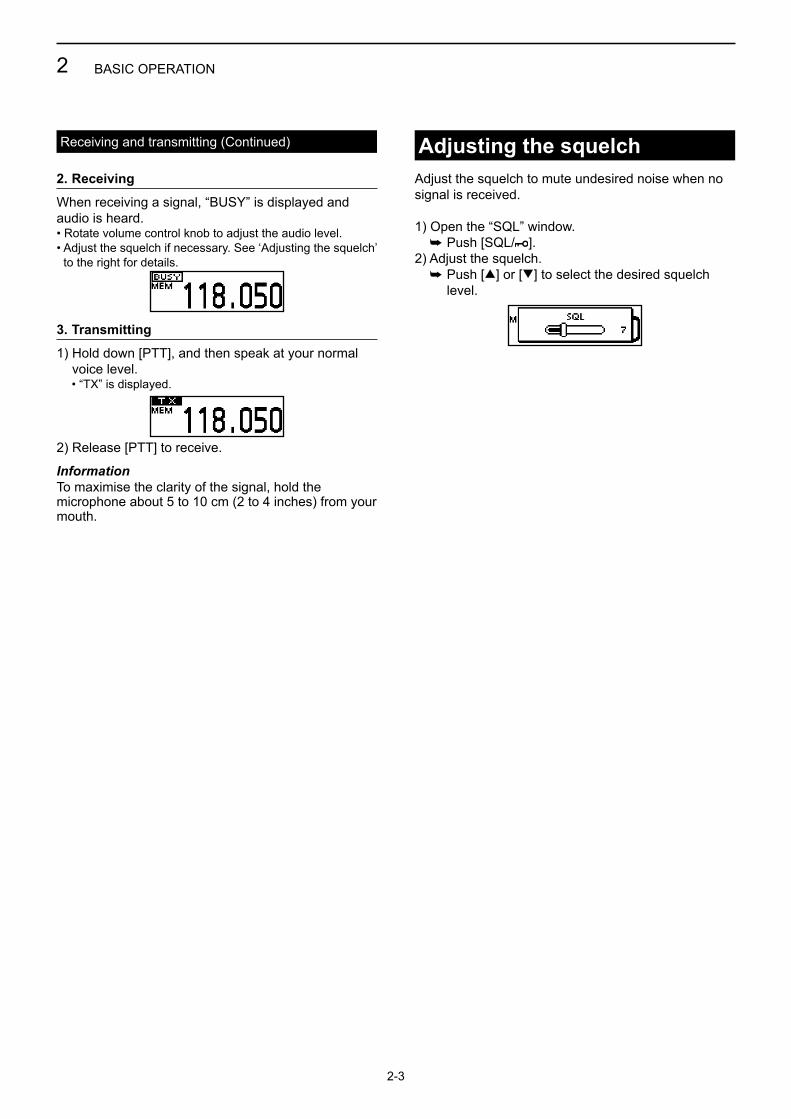
Adjusting the squelchAdjust the squelch to mute undesired noise when no signal is received.
1) Open the “SQL” window. ➥ Push [SQL/ ]. 2) Adjust the squelch. ➥ Push [∫] or [√] to select the desired squelch
level.
2. Receiving
When receiving a signal, “BUSY” is displayed and audio is heard.• Rotate volume control knob to adjust the audio level.• Adjust the squelch if necessary. See ‘Adjusting the squelch’
to the right for details.
3. Transmitting
1) Hold down [PTT], and then speak at your normal voice level.
• “TX” is displayed.
2) Release [PTT] to receive.
InformationTo maximise the clarity of the signal, hold the microphone about 5 to 10 cm (2 to 4 inches) from your mouth.
Receiving and transmitting (Continued)
3-1
Section 3 SCAN OPERATIONScan types..............................................................................3-2
D Memory channnel scan ....................................................................3-2 D Priority scan .....................................................................................3-2 D VFO scan .........................................................................................3-2
Scan settings .........................................................................3-2 D Selecting Scan types .......................................................................3-2 D Setting the Resume timer ................................................................3-2 D On-Hook scan ..................................................................................3-2 D Setting the stop/TX channel. ............................................................3-2

The IC-A120/IC-A120E have different types of scan described below to search for signals.
D Memory channel scan Repeatedly scans memory channels belonging to the same group except locked out channels.
D Priority scanWhile scanning the Memory channel, Priority watch checks for a signal on the selected Priority channel.
D VFO scan (For only EXP, USA and EUR versions.)Repeatedly scans all frequencies over the entire band.
Customize the Scan settings in the Menu mode. When you push [SCAN], the transceiver starts scanning according to the settings described below.
D Selecting Scan typesSelect the desired scan type in the “SCAN TYPE” item before scanning (p. 7-6).
MENU > SETTINGS > SCAN > SCAN TYPE
D Setting the Resume timerSet the period of time to resume scanning after the receiving signal disappears (p. 7-6).
MENU > SETTINGS > SCAN > RESUME TIMER
D On-Hook scanThe transceiver scans for signals while the microphone is on the hook, depending on the setting(p. 7-6).
MENU > SETTINGS > SCAN > ON-HOOK SCAN
D Setting the stop/TX channel.Select the channel that the On-Hook scan stops on when you remove the microphone from the hook, and the channel to transmit on when you push [PTT] while the Dualwatch function is ON (p. 7-6).
MENU > SETTINGS > SCAN > STOP/TX CH
3 SCAN OPERATION
3-2
Scan types
Mch 1
Mch 2
Mch 3
Mch 200
Locked out channel
Lowestfrequency
HighestfrequencyStart
Scan
Jump
Priority channel
Mch 1Mch 2Mch 3
Mch 200
Locked out channel
NOTE: The Scan function may be disabled, depending on the transceiver’s setting. Ask your authorized Icom dealer or transceiver administrator for details.
Scan settings

4-1
Section 4 MEMORY OPERATIONGeneral description ...............................................................4-2Editing a Memory channel ....................................................4-2
D Editing the memory name ................................................................4-2 D Deleting a Memory channel .............................................................4-2
Entering contents into the Memory channels .....................4-3
4 MEMORY OPERATION
4-2
General descriptionThe IC-A120/IC-A120E has 200 memories to store frequently used channels. You can assign the stored channel to up to 10 groups.
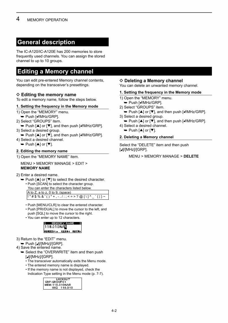
You can edit pre-entered Memory channel contents, depending on the transceiver’s presettings.
D Editing the memory nameTo edit a memory name, follow the steps below.
1. Setting the frequency in the Memory mode1) Open the “MEMORY” menu. ➥ Push [ /MHz/GRP]. 2) Select “GROUPS” item. ➥ Push [∫] or [√], and then push [ /MHz/GRP]. 3) Select a desired group. ➥ Push [∫] or [√], and then push [ /MHz/GRP]. 4) Select a desired channel. ➥ Push [∫] or [√].
2. Editing the memory name1) Open the “MEMORY NAME” item.
MENU > MEMORY MANAGE > EDIT > MEMORY NAME
2) Enter a desired name. ➥ Push [∫] or [√] to select the desired character. • Push [SCAN] to select the character group. You can enter the characters listed below.
• Push [MENU/CLR] to clear the entered character. • Push [PRI/DUAL] to move the cursor to the left, and
push [SQL] to move the cursor to the right. • You can enter up to 12 characters.
3) Return to the “EDIT” menu. ➥ Push [ ]/[MHz]/[GRP].4) Save the entered name. ➥ Select the “OVERWRITE” item and then push [ ]/[MHz]/[GRP]. • The transceiver automatically exits the Menu mode. • The entered memory name is displayed. • If the memory name is not displayed, check the
Indication Type setting in the Menu mode (p. 7-7).
Editing a Memory channel
A to Z, a to z, 0 to 9, (space)! " # $ % & ' ( ) * + , - . / : ; < = > ? @ [ \ ] ^ _ ` { | } ~
D Deleting a Memory channelYou can delete an unwanted memory channel.
1. Setting the frequency in the Memory mode1) Open the “MEMORY” menu. ➥ Push [ /MHz/GRP]. 2) Select “GROUPS” item. ➥ Push [∫] or [√], and then push [ /MHz/GRP]. 3) Select a desired group. ➥ Push [∫] or [√], and then push [ /MHz/GRP]. 4) Select a desired channel. ➥ Push [∫] or [√].
2. Deleting a Memory channel
Select the “DELETE” item and then push [ ]/[MHz]/[GRP].
MENU > MEMORY MANAGE > DELETE
4 MEMORY OPERATION
4-3
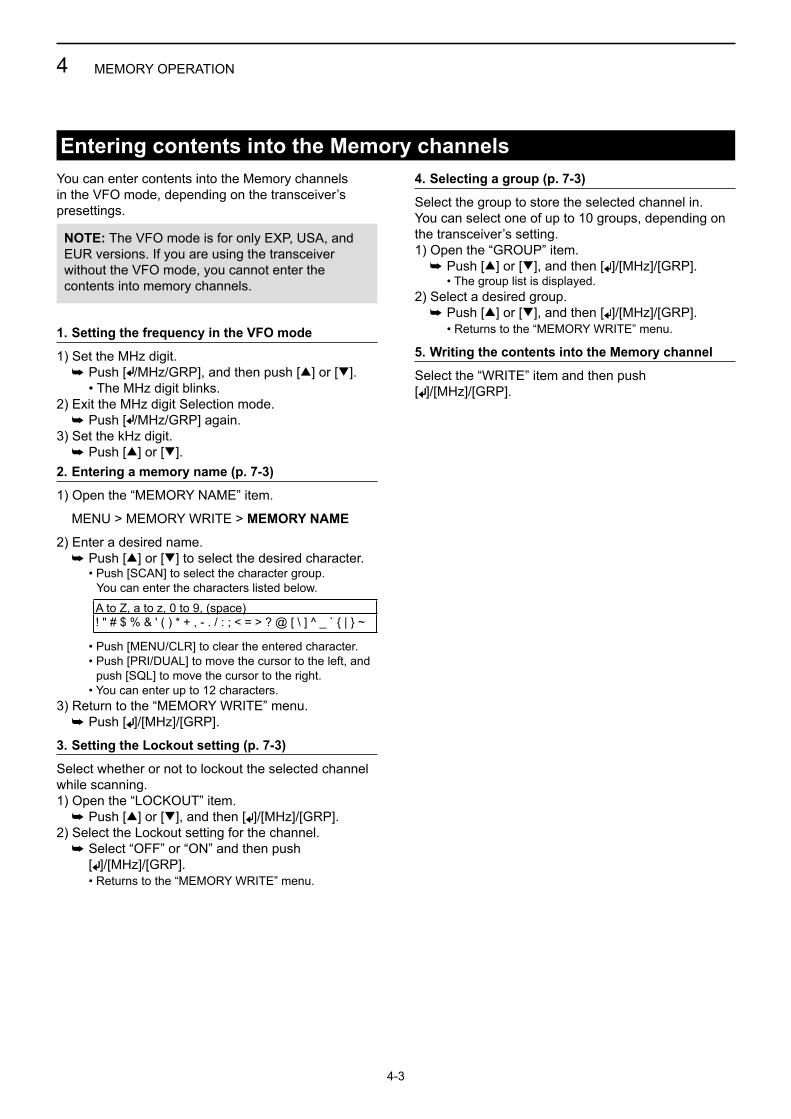
You can enter contents into the Memory channels in the VFO mode, depending on the transceiver’s presettings.
1. Setting the frequency in the VFO mode
1) Set the MHz digit. ➥ Push [ /MHz/GRP], and then push [∫] or [√]. • The MHz digit blinks.2) Exit the MHz digit Selection mode. ➥ Push [ /MHz/GRP] again.3) Set the kHz digit. ➥ Push [∫] or [√].2. Entering a memory name (p. 7-3)
1) Open the “MEMORY NAME” item.
MENU > MEMORY WRITE > MEMORY NAME
2) Enter a desired name. ➥ Push [∫] or [√] to select the desired character. • Push [SCAN] to select the character group. You can enter the characters listed below. A to Z, a to z, 0 to 9, (space)
! " # $ % & ' ( ) * + , - . / : ; < = > ? @ [ \ ] ^ _ ` { | } ~
• Push [MENU/CLR] to clear the entered character. • Push [PRI/DUAL] to move the cursor to the left, and
push [SQL] to move the cursor to the right. • You can enter up to 12 characters.3) Return to the “MEMORY WRITE” menu. ➥ Push [ ]/[MHz]/[GRP].
3. Setting the Lockout setting (p. 7-3)
Select whether or not to lockout the selected channel while scanning.1) Open the “LOCKOUT” item. ➥ Push [∫] or [√], and then [ ]/[MHz]/[GRP].2) Select the Lockout setting for the channel. ➥ Select “OFF” or “ON” and then push [ ]/[MHz]/[GRP]. • Returns to the “MEMORY WRITE” menu.
Entering contents into the Memory channels4. Selecting a group (p. 7-3)
Select the group to store the selected channel in.You can select one of up to 10 groups, depending on the transceiver’s setting.1) Open the “GROUP” item. ➥ Push [∫] or [√], and then [ ]/[MHz]/[GRP]. • The group list is displayed.2) Select a desired group. ➥ Push [∫] or [√], and then [ ]/[MHz]/[GRP]. • Returns to the “MEMORY WRITE” menu.
5. Writing the contents into the Memory channel
Select the “WRITE” item and then push [ ]/[MHz]/[GRP].
NOTE: The VFO mode is for only EXP, USA, and EUR versions. If you are using the transceiver without the VFO mode, you cannot enter the contents into memory channels.

5-1
Section 5 OTHER FUNCTIONSPriority channel .....................................................................5-2
D Setting the Priority channel ..............................................................5-2
Dualwatch operation .............................................................5-2

The Priority channel enables you to have quick accessto a specific channel. You can set one of the Memory channels as the Priority channel.
D Setting the Priority channel1) Open the “PRIORITY CH” menu.
MENU > SETTINGS > FUNCTIONS > PRIORITY CH
• The channel set as the Priority channel is displayed. • “OFF” is displayed if no channel is set as the Priority
channel.
2) Open the “GROUP” menu. ➥ Push [ /MHz/GRP].3) Select the desired group. ➥ Push [∫] or [√] and then push [ /MHz/GRP].4) Select the desired channel. ➥ Push [∫] or [√] and then push [ /MHz/GRP]. • “Returns to the “PRIORITY CH” menu. • “The selected channel is displayed as the Priority
channel.
5 OTHER FUNCTIONS
5-2
Priority channel
NOTE: The Priority channel may be disabled, depending on the transceiver’s setting. Ask your authorized Icom dealer or transceiver administrator for details.
Dualwatch operationDualwatch monitors the Priority channel while a VFO* or Memory channel is selected.If a signal is received on the Priority channel, Dualwatch changes to the Priority channel until the Priority signal disappears. Dualwatch then returns to the selected other channel.*For only EXP, USA, and EUR versions.
Hold down [PRI/DUAL] for 1 second to turn ON the Dualwatch function.• The Priority channel is displayed under the selected
channel.• The Priority channel’s name may be displayed, depending
on the Indication Type setting. See page 7-7 for details.
• When a signal is received on the Priority channel, “PRI” blinks and the Priority channel is displayed larger than the selected channel.
• If the “STOP/TX CH” item’s setting in the menu mode (p. 7-6) is set to “PRIORITY CH,” “TX:PRI” is displayed as shown below.

6-1
Section 6 Bluetooth® OPERATIONOperating Bluetooth® ............................................................6-2Electromagnetic interference ...............................................6-2Pairing with a headset...........................................................6-3Connecting a paired headset ...............................................6-3Setting AF output ..................................................................6-3Disconnecting a headset ......................................................6-4Unpairing a headset ..............................................................6-4
6 Bluetooth® OPERATION
6-2
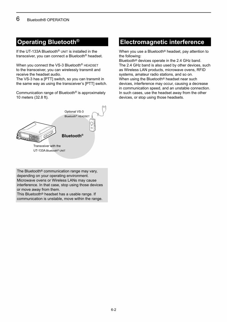
If the UT-133A Bluetooth® unit is installed in the transceiver, you can connect a Bluetooth® headset.
When you connect the VS-3 Bluetooth® headset to the transceiver, you can wirelessly transmit and receive the headset audio.The VS-3 has a [PTT] switch, so you can transmit in the same way as using the transceiver’s [PTT] switch.
Communication range of Bluetooth® is approximately 10 meters (32.8 ft).
Operating Bluetooth®
The Bluetooth® communication range may vary, depending on your operating environment.Microwave ovens or Wireless LANs may cause interference. In that case, stop using those devices or move away from them.This Bluetooth® headset has a usable range. If communication is unstable, move within the range.
Bluetooth®
Electromagnetic interferenceWhen you use a Bluetooth® headset, pay attention to the following:Bluetooth® devices operate in the 2.4 GHz band.The 2.4 GHz band is also used by other devices, such as Wireless LAN products, microwave ovens, RFID systems, amateur radio stations, and so on. When using the Bluetooth® headset near such devices, interference may occur, causing a decrease in communication speed, and an unstable connection.In such cases, use the headset away from the other devices, or stop using those headsets.
Transceiver with theUT-133A Bluetooth® unit
Optional vs-3Bluetooth® headset

6 Bluetooth® OPERATION
6-3
Pairing with a headsetThese instructions describe pairing with the VS-3 Bluetooth® headset. You can pair a maximum of 7 Bluetooth® headsets with the transceiver.• If you try to pair a Bluetooth® headset to a transceiver that
already has 7 headsets paired with it, the oldest headset will automatically be unpaired.
1. Turning ON transceiver’s Bluetooth® function
1) Open the “BLUETOOTH FUNC” item. MENU > SETTINGS > BLUETOOTH
> BLUETOOTH FUNC
2) Activate the Bluetooth® unit. ➥ Select “ON” and push [ /MHz/GRP].
2. Entering the Pairing mode of the VS-3• See the VS-3’s instruction manual for details.
3. Pairing the Bluetooth® headset
1) Open the “DEVICE SEARCH” item. MENU > BLUETOOTH > PAIR/CONNECT
> DEVICE SEARCH
2) Search for a headset to pair. ➥ Select “HEADSET” and push [ /MHz/GRP]. • The found headsets are displayed. • “NOT FOUND” is displayed if no headset is found. • Push [MENU/CLR] to cancel searching. • The headset name changes to its Bluetooth® device
address in 5 seconds.
3) Select the desired headset to pair. ➥ Push [∫] or [√] and then push [ /MHz/GRP]. • A passkey or PIN code may be required to
pair, depending on the headset. Refer to your headset’s instructions for details.
4) Exit the Menu mode. ➥ Push [ ]. • “ ” is displayed if the headset is correctly paired.
If you have a previously paired headset, follow the steps below to connect it. 1) Open the “PAIR/CONNECT” menu. MENU > BLUETOOTH > PAIR/CONNECT
• The paired headsets are displayed.2) Select the desired headset to connect. ➥ Push [∫] or [√] and then push [ /MHz/GRP]. • “CONNECT” and “UNPAIR” is displayed.3) Connect the headset. ➥ Select “CONNECT” and then push
[ /MHz/GRP]. • The check mark “4” in the box is displayed.
4) Exit the Menu mode. ➥ Push [ ].
Setting AF outputYou can select the AF output option in the “AF OUTPUT” item.MENU > SETTINGS > BLUETOOTH > HEADSET SET > AF OUTPUT
HEADSET: Outputs audio to the connected Bluetooth® headset.
HEADSET & SPEAKER: Outputs audio to both the connected Bluetooth® headset and the transceiver’s speaker.
Connecting a paired headset
6 Bluetooth® OPERATION
6-4
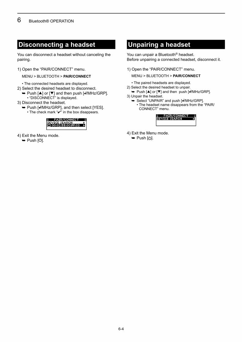
Disconnecting a headset Unpairing a headsetYou can disconnect a headset without canceling the pairing.
1) Open the “PAIR/CONNECT” menu. MENU > BLUETOOTH > PAIR/CONNECT
• The connected headsets are displayed.2) Select the desired headset to disconnect. ➥ Push [∫] or [√] and then push [ /MHz/GRP]. • “DISCONNECT” is displayed.3) Disconnect the headset. ➥ Push [ /MHz/GRP], and then select [YES]. • The check mark “4” in the box disappears.
4) Exit the Menu mode. ➥ Push [ ].
You can unpair a Bluetooth® headset.Before unpairing a connected headset, disconnect it.
1) Open the “PAIR/CONNECT” menu.
MENU > BLUETOOTH > PAIR/CONNECT
• The paired headsets are displayed.2) Select the desired headset to unpair. ➥ Push [∫] or [√] and then push [ /MHz/GRP].3) Unpair the headset. ➥ Select “UNPAIR” and push [ /MHz/GRP]. • The headset name disappears from the “PAIR/
CONNECT” menu.
4) Exit the Menu mode. ➥ Push [ ].

7-1
Section 7 MENU MODEUsing the Menu mode ...........................................................7-2Menu mode items ..................................................................7-3VFO MODE/MEMORY MODE group .....................................7-3MEMORY WRITE group .........................................................7-3
D MEMORY NAME .............................................................................7-3 D LOCKOUT ........................................................................................7-3 D GROUP ............................................................................................7-3 D GROUP NAME ................................................................................7-3 D WRITE .............................................................................................7-3
MEMORY MANAGE group ....................................................7-4EDIT .................................................................................7-4
D MEMORY NAME .............................................................................7-4 D LOCKOUT ........................................................................................7-4 D GROUP NAME ................................................................................7-4 D OVERWRITE ...................................................................................7-4
DELETE ...........................................................................7-4BLUETOOTH group ...............................................................7-4 PAIR/CONNECT ..............................................................7-4
D DEVICE SEARCH............................................................................7-4
PAIRING STANDBY .........................................................7-4SETTINGS group ...................................................................7-5
FUNCTIONS ....................................................................7-5 D CH SPACING ...................................................................................7-5 D PRIORITY CH ..................................................................................7-5 D NOISE LIMITING .............................................................................7-5 D TIME OUT TIMER ............................................................................7-5 D MIC KEY CUSTOMIZE ....................................................................7-5 D LOCK FUNCTION ............................................................................7-6 D CI-V ..................................................................................................7-6
SCAN ...............................................................................7-6 D SCAN TYPE .....................................................................................7-6 D RESUME TIMER .............................................................................7-6 D ON-HOOK SCAN ............................................................................7-6 D STOP/TX CH ...................................................................................7-6
DISPLAY ..........................................................................7-7 D LCD BACKLIGHT ............................................................................7-7 D LCD CONTRAST .............................................................................7-7 D INDICATION TYPE ..........................................................................7-7
SOUNDS ..........................................................................7-7 D KEY BEEP .......................................................................................7-7 D BEEP LEVEL ...................................................................................7-7 D SIDE TONE ......................................................................................7-7 D SPEAKER OUTPUT ........................................................................7-7
BLUETOOTH ...................................................................7-8 D BLUETOOTH FUNC ........................................................................7-8 D AUTO CONNECT ............................................................................7-8 D HEADSET SET ................................................................................7-8 D DATA DEVICE SET ..........................................................................7-9 D DEVICE INFO .................................................................................7-9 D DEVICE INITIALIZE .........................................................................7-9
INFORMATION ................................................................7-9 D VERSION .........................................................................................7-9
7 MENU MODE
7-2
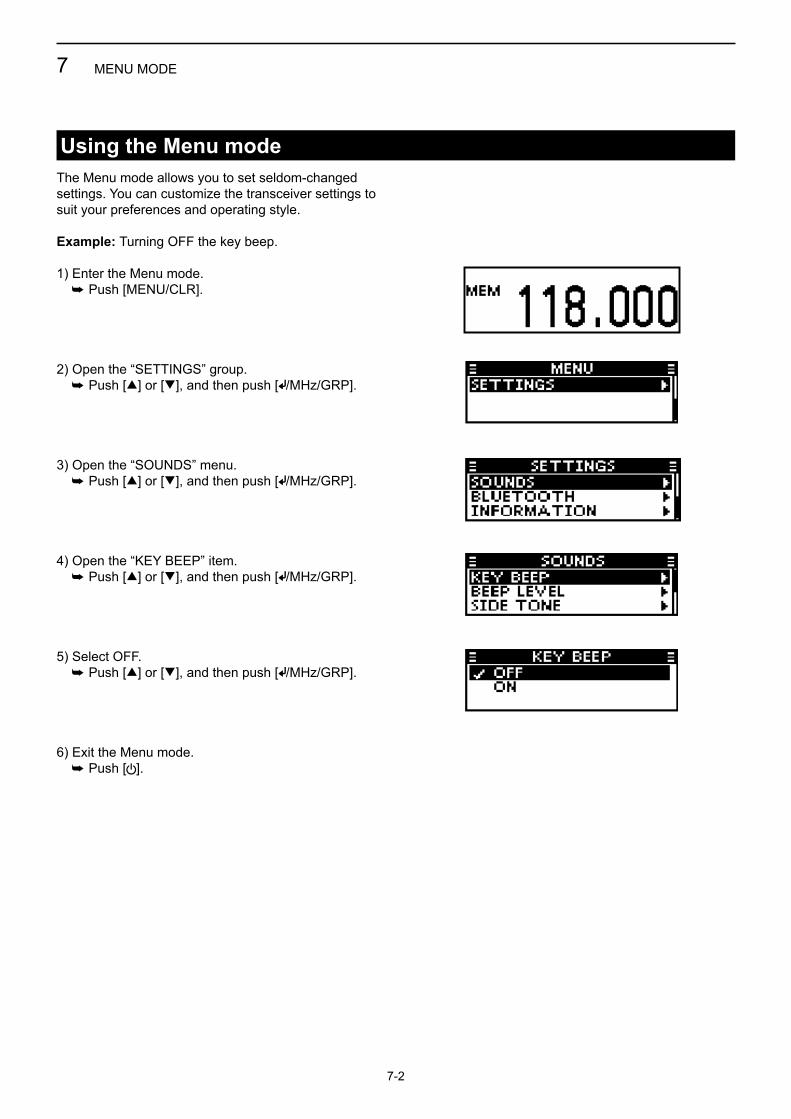
Using the Menu modeThe Menu mode allows you to set seldom-changed settings. You can customize the transceiver settings to suit your preferences and operating style.
Example: Turning OFF the key beep.
1) Enter the Menu mode. ➥ Push [MENU/CLR].
2) Open the “SETTINGS” group. ➥ Push [∫] or [√], and then push [ /MHz/GRP].
3) Open the “SOUNDS” menu. ➥ Push [∫] or [√], and then push [ /MHz/GRP].
4) Open the “KEY BEEP” item. ➥ Push [∫] or [√], and then push [ /MHz/GRP].
5) Select OFF. ➥ Push [∫] or [√], and then push [ /MHz/GRP].
6) Exit the Menu mode. ➥ Push [ ].

7 MENU MODE
7-3
Menu mode itemsThe menu items contained in the transceiver may be different, depending on the transceiver’s setting. Ask your dealer or transceiver administrator for details.
Switch the transceiver to the VFO mode or Memory mode.Displays “VFO MODE” group when the transceiver is in the Memory mode, and displays “MEMORY MODE” group when the transceiver is in the VFO mode.
VFO MODE/MEMORY MODE group(For only EXP, USA, and EUR versions.)
MEMORY WRITE group(May not be displayed, depending on the transceiver’s presettings.)
D MEMORY NAMEEnter the memory name when you enter the frequency in the Memory channel.You can enter the characters listed below.
A to Z, a to z, 0 to 9, (space)! " # $ % & ' ( ) * + , - . / : ; < = > ? @ [ \ ] ^ _ ` { | } ~
D LOCKOUTSelect whether or not to lockout the selected channel while scanning.• OFF: The channel will not be locked out while
scanning.• ON: The channel will be locked out while scanning.
D GROUPSelect the group to store the selected channel in.You can select one of up to 10 groups, depending on the transceiver’s setting.
D GROUP NAMEEnter a group name of up to 12 characters.You can enter the characters listed below.
A to Z, a to z, 0 to 9, (space)! " # $ % & ' ( ) * + , - . / : ; < = > ? @ [ \ ] ^ _ ` { | } ~
D WRITESave the entered settings in the MEMORY WRITE group items.
In the Memory mode In the VFO mode

7 MENU MODE
7-4
■ EDIT D MEMORY NAME
Edit a selected Memory channel’s name.You can enter the characters listed below.
A to Z, a to z, 0 to 9, (space)! " # $ % & ' ( ) * + , - . / : ; < = > ? @ [ \ ] ^ _ ` { | } ~
D LOCKOUTSelect whether or not to lock out the selected channel while scanning.• OFF: The channel will not be locked out while
scanning.• ON: The channel will be locked out while scanning.
D GROUP NAMEEdit a Group name. You can enter the characters listed below.
A to Z, a to z, 0 to 9, (space)! " # $ % & ' ( ) * + , - . / : ; < = > ? @ [ \ ] ^ _ ` { | } ~
D OVERWRITESave the edited settings in the MEMORY MANAGE group items.
■ DELETEDelete a selected Memory channel.
MEMORY MANAGE group(May not be displayed, depending on the transceiver’s presettings.)
■ PAIR/CONNECTDisplays the paired Bluetooth® headsets and devices.
D DEVICE SEARCHSearch for a Bluetooth® headset or a Bluetooth® data device to pair and connect.• HEADSET: Search for a Bluetooth® headset.• DATA DEVICE: Search for a Bluetooth® data device.
■ PAIRING STANDBYWait for the pairing request from a Bluetooth® headset or a Bluetooth® data device.
BLUETOOTH group(Displayed only when the optional UT-133A Bluetooth® unit is installed.)
7 MENU MODE
7-5
■ FUNCTIONS D CH SPACING
(May not be displayed, depending on the transceiver’s presettings.)
Select “8.33 kHz,” “25 kHz,” or “8.33 kHz/25 kHz” channel spacing.
D PRIORITY CH (May not be displayed, depending on the
transceiver’s presettings.)Select the Priority channel from the Memory channels stored in the transceiver (p. 5-2).• The channel set as the Priority channel is displayed.• “OFF” is displayed if no channel is set as the Priority
channel.
D NOISE LIMITINGSet the noise limiting function for receiving and transmitting.
RX• OFF: The Noise Limiting function is OFF.• ANL: The Automatic Noise Limiter (ANL) is ON.• LOW: Reduces the received signal noise level to 1/2
of normal.• MID: Reduces the received signal noise level to 1/3
of normal.• HIGH: Reduces the received signal noise level to
1/10 of normal.
TX• OFF: The Noise Limiting function is OFF.• ON: The Noise Limiting function is ON.
D TIME OUT TIMER (May not be displayed, depending on the
transceiver’s presettings.)The Time-out Timer (TOT) limits continuous transmissions on the channel, to prevent occupying the channel for a long time.• OFF*1: The Time-out Timer is disabled.• 30 sec to 180 sec: Sets the Time-out Timer to
between 30 seconds and 180 seconds.
*1 Except IC-A120E (AUS version).
D MIC KEY CUSTOMIZE (May not be displayed, depending on the
transceiver’s presettings.)You can customize the key assignment for the optional HM-217 speaker micrOphOne (p. 9-3).
[P1]/[P2]• VFO/MR MODE*2: Push to change the
operating mode.• PRIORITY CH: Push to select the Priority
channel.• DUALWATCH: Push to check the Priority
channel while receiving another channel.
• SCAN START/PAUSE: Push to start a scan. Push again to pause the scan
• SQL Push to adjust the squelch. (p. 2-3)
• VOL Push to adjust the volume. • LOCK Push to turn the Key Lock
function ON or OFF.• --- No function is assigned.
*2 For only USA, EXP and EUR versions.
[UP]/[DOWN]• UP/DOWN: Push to select the channel.• VOL UP/DOWN: Push to adjust the volume
level.• SQL UP/DOWN: Push to adjust the squelch
level.• --- No function is assigned.
D LOCK FUNCTIONSelect an option for the Key Lock function.• All: Locks all keys.• Microphone Key: Locks the keys on the
microphone.• Panel Key: Locks the keys on the
transceiver.
SETTINGS group
CAUTION: In Canada, use of 8.33 kHz Channel Spacing of this radio is strictly prohibited and shall not be used.

7 MENU MODE
7-6
SETTINGS group
■ Functions (Continued) D CI-V
(May not be displayed, depending on the transceiver’s presettings.)
CI-V addressTo distinguish equipment, each CI-V transceiver has its own Icom standard address in hexadecimal code.The IC-A120/IC-A120E’s default address is 92.When 2 or more transceivers are controlled through a PC at the same time, set a different address for each transceiver.
CI-V baud rateSet the CI-V data transfer speed. • 4800 BPS to 19200 BPS: Sets the data transfer
speed to between 4800 bps and 19200 bps.
• AUTO: The baud rate is automatically set according to the data rate of the controller.
CI-V transceiveTurn the CI-V Transceive function ON or OFF.• OFF: Turns OFF the function.• ON: When you change a setting on one
transceiver, the same setting is automatically changed on other connected transceivers.
■ SCAN D SCAN TYPE
(May not be displayed, depending on the transceiver’s presettings.)
Select the scan type. When you push [SCAN], the scan proceeds according to this setting.• NORMAL: Push [SCAN] to start a Normal scan.• PRIORITY: Push [SCAN] to start a Priority scan.
D RESUME TIMER (May not be displayed, depending on the
transceiver’s presettings.)When a received signal disappears, the scan resumes according to this setting. Set the Resume Timer to between 3 seconds and 10 seconds.
D ON-HOOK SCAN (May not be displayed, depending on the
transceiver’s presettings.)Set the On-Hook scan function (p.3-2) to ON or OFF.• OFF: The On-Hook scan function is OFF.• ON: The On-Hook scan function is ON.
D STOP/TX CH (May not be displayed, depending on the
transceiver’s presettings.)Select the channel that On-Hook scan stops on when you remove the microphone from the hook, and the channel to transmit on when you push [PTT] in Dualwatch operation.• SCAN CH: The displayed channel is used as the
scan stop channel during an On-Hook scan, and as the transmit channel.
• PRIORITY CH: The Priority channel is used as the scan stop channel during an On-Hook scan, and as the transmit channel.

7 MENU MODE
7-7
SETTINGS group (Continued)
■ DISPLAY D LCD BACKLIGHT
Sets the LCD backlight brightness level to between 0 and 3.
D LCD CONTRASTSets the LCD contrast level to between 1 and 10.
D INDICATION TYPESelect the indication type for Function display in the Memory mode.• FREQ: Displays frequency on the Function
display.• NAME: Displays channel name on the
Function display.• FREQ & NAME: Displays frequency and channel
name on the Function display.
■ SOUNDS D KEY BEEP
Set the key beep to ON or OFF.• OFF: The key beep is OFF.• ON: The key beep is ON.
D BEEP LEVELSets the beep level to between 1 and 10 or OFF.
D SIDE TONEThe Side tone function outputs the transmitting audio to the VS-3 Bluetooth® headset or the headset connected to the transceiver with OPC-871A headset adapter.Sets the Side tone level to between 1 and 10 or OFF.
D SPEAKER OUTPUTSelect the speaker output setting.• OFF: No audio is heard from any speaker.• AUTO: If an external speaker is connected to
the transceiver, the audio is heard from the external speaker.
If an external speaker is not connected to the transceiver, the audio is heard from the internal speaker.
• INTERNAL: The audio is heard from only the Internal speaker.
• EXTERNAL: The audio is heard from only the External speaker.
• INT & EXT: The audio is heard from both the internal speaker and the external speaker.

7 MENU MODE
7-8
SETTINGS group (Continued)
■ BLUETOOTHThe items in the “BLUETOOTH” menu are displayed only when the UT-133A Bluetooth® unit is installed.
D BLUETOOTH FUNCTurn the Bluetooth® function ON or OFF.• OFF: The Bluetooth® function is OFF.• ON: The Bluetooth® function is ON.
D AUTO CONNECT (May not be displayed, depending on the
transceiver’s presettings.)Select whether or not to automatically connect to the last bonded Bluetooth® headset.• OFF: The user has to manually connects to the
Bluetooth® headset.• ON: The transceiver automatically connects to the
last bonded Bluetooth® headset.
D HEADSET SET
AF OUTPUTSelect the AF output option.• HEADSET: Outputs audio to the Bluetooth®
headset.• HEADSET & SPEAKER: Outputs audio to both the
Bluetooth® headset and the internal speaker.
BT HEADSET USE (May not be displayed, depending on the
transceiver’s presettings.)Select which device’s audio and PTT to use when a Bluetooth® headset and the microphone are connected to the transceiver.• NORMAL: Transmits the audio from the
device whose [PTT] is pushed.• MIC: Transmits the audio from the
Bluetooth® headset.• PTT (MAIN MIC): The transmission is made
by pushing [PTT] on the Bluetooth® headset.
Transmits the audio from the hand microphone.
• PTT (MAIN HS MIC): The transmission is made by pushing [PTT] on the Bluetooth® headset.
Transmits the audio from the headset connected to the transceiver with the optional OPC-871A headset adapter.
ICOM HEADSET (May not be displayed, depending on the
transceiver’s presettings.)
POWER SAVE:Select whether or not to use the Battery Saving mode with VS-3 Bluetooth® headset.• OFF: The Power Save mode is OFF.• ON: The Power Save mode is temporalily activated
if the connected VS-3 Bluetooth® headset is not used for 120 seconds.
ONE-TOUCH PTT:This function enables you to communicate with a single push of the VS-3 Bluetooth® headset's [PTT].Select whether or not to enable the One-Touch PTT function.• OFF: The function is OFF.• ON: The function is ON.
PTT BEEP:Set the beep sound when pushing [PTT] on the optional VS-3 Bluetooth® headset.• OFF: No beep sounds when you push VS-3's [PTT].• ON: Beep sounds when you push VS-3's [PTT].

7 MENU MODE
7-9
D DATA DEVICE SET (May not be displayed, depending on the
transceiver’s presettings.)
BT CI-VSelect whether or not to send back the serial data received from the Bluetooth® SPP (Serial Port Profile) on a connected device when sending or receiving a CI-V command.• ECHO BACK OFF: The serial data will not be
send back.• ECHO BACK ON: The serial data will be sent
back.
D DEVICE INFO Displays the information of the UT-133A Bluetooth®
unit. You can edit the unit’s name.• Push [ ]/[MHz]/[GRP] to edit the unit’s name.
D DEVICE INITIALIZE (May not be displayed, depending on the
transceiver’s presettings.)Initialize the UT-133A Bluetooth® unit, and then reboot the transceiver.
■ INFORMATION D VERSION
Displays your transceiver’s firmware version number.
SETTINGS group (Continued)

8-1
Section 8 CONNECTION AND INSTALLATIONRear panel connection ..........................................................8-2Mounting the transceiver ......................................................8-3Supplied accessories ............................................................8-4

q
e
w
r
t
8 CONNECTION AND INSTALLATION
8-2
Rear panel connection
Antenna
Microphone
Black
Red
12 V or 24 V* Battery
R WARNING! NEVER remove the fuse holders from the DC power cable.
NOTE: Use the terminals as shown below for the cable connections.
Crimp Solder
q ANTENNA CONNECTOR Connect an antenna cable.w HEADSET ADAPTER CONNECTOR Connect an optional OPC-871A headset adapter. Ask your dealer for details.
e MICROPHONE HANGER Connect the supplied
microphone hanger to the vehicle’s ground to use the microphone ON/OFF hook functions.
t DC POWER RECEPTACLE Connects to a 12 V or 24 V*
DC power source. Pay attention to polarities.
R WARNING! NEVER connect the transceiver to a power source of more than 31.5 V DC. This could damage the transceiver.
r EXTERNAL SPEAKER JACK Connectan8Ωexternalspeaker
* The transceiver automatically adjusts to the input voltage.
Microphonehanger cable

8 CONNECTION AND INSTALLATION
8-3
Mounting the transceiver
Flat washer
Felt*
Spring washer
When usingself-tapping screws
*Felt reduces vibration

8 CONNECTION AND INSTALLATION
8-4
Supplied accessories
Microphone Microphone hanger Microphonehanger cable
DC power cable Mounting bracket Sponges*
Flat washers Bracket bolts Self-tapping screws(5×16)
Spring washers Mounting screws(5×12)
Nuts Fuses (10 A)
* Used to install the optional UT-133A Bluetooth® unit. Ask your dealer for details.
Self-tapping screws(3×16, for Microphone hanger)

9-1
Section 9 SPECIFICATIONS AND OPTIONSSpecifications ........................................................................9-2
D General ............................................................................................9-2 D Transmitter .......................................................................................9-2 D Receiver ...........................................................................................9-3
Options ...................................................................................9-3
9 SPECIFICATIONS AND OPTIONS
9-2
SpecificationsIn Canada, Use of 8.33 kHz Channel Spacing of this radio is strictly prohibited and shall not be used.
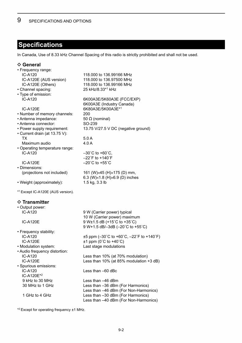
D General• Frequency range: IC-A120 118.000 to 136.99166 MHz IC-A120E (AUS version) 118.000 to 136.97500 MHz IC-A120E (Others) 118.000 to 136.99166 MHz• Channel spacing: 25 kHz/8.33*1 kHz• Type of emission: IC-A120 6K00A3E/5K60A3E (FCC/EXP) 6K00A3E (Industry Canada) IC-A120E 6K80A3E/5K00A3E*1
• Number of memory channels: 200• Antenna impedance: 50 ø (nominal)• Antenna connector: SO-239• Power supply requirement: 13.75 V/27.5 V DC (negative ground)• Current drain (at 13.75 V): TX 5.0 A Maximum audio 4.0 A• Operating temperature range: IC-A120 –30˚Cto+60˚C, –22˚Fto+140˚F IC-A120E –20˚Cto+55˚C• Dimensions: (projections not included) 161 (W)✕45 (H)✕175 (D) mm, 6.3 (W)✕1.8 (H)✕6.9 (D) inches• Weight (approximately): 1.5 kg, 3.3 lb
*1 Except IC-A120E (AUS version).
D Transmitter• Output power: IC-A120 9 W (Carrier power) typical 10 W (Carrier power) maximum IC-A120E 9W±1.5dB(+15˚Cto+35˚C) 9W+1.5dB/–3dB(–20˚Cto+55˚C)• Frequency stability: IC-A120 ±5ppm(–30˚Cto+60˚C,–22˚Fto+140˚F) IC-A120E ±1ppm(0˚Cto+40˚C)• Modulation system: Last stage modulations• Audio frequency distortion: IC-A120 Less than 10% (at 70% modulation) IC-A120E Lessthan10%(at85%modulation+3dB)• Spurious emissions: IC-A120 Less than –60 dBc IC-A120E*2
9 kHz to 30 MHz Less than –46 dBm 30 MHz to 1 GHz Less than –36 dBm (For Harmonics) Less than –46 dBm (For Non-Harmonics) 1 GHz to 4 GHz Less than –30 dBm (For Harmonics) Less than –40 dBm (For Non-Harmonics)
*2 Except for operating frequency ±1 MHz.

HM-217 speaker micrOphOneThe speaker microphone with [∫]/[√] keys and [P1]/[P2] keys.
You can customize the key assignment in the Menu mode (p. 7-5).
VS-3 Bluetooth® headsetThe Bluetooth® headset with a [PTT] switch.
UT-133A Bluetooth® unit
OPC-871A headset adapterThe adapter to connect a standard headset.
OPC-478UC clOning cableThe cable to connect a PC and the OPC-592 clOning cable adapter when you control the transceiver with the CI-V commands (p. 10-2).
OPC-592 clOning cable adapterThe cable adapter to connect the transceiver and the OPC-478UC clOning cable when you control the transceiver with the CI-V commands (p. 10-2).
D Receiver• Receive system: Double conversion superheterodyne• Intermediate frequencies: 1st 38.85 MHz 2nd 450 kHz• Sensitivity: IC-A120 Lessthan1μV(pd)(at6dBS/N) IC-A120E Less than –101 dBm (12 dB SINAD with CCITT)• Squelch sensitivity: IC-A120 Lessthan0.35μV(pd) IC-A120E Less than –116 dBm• Spurious response rejection ratio: IC-A120 More than 5 mV (pd) IC-A120E More than 70 dB• Audio output power: External speaker More than 10 W (at13.75VDCwith8Ωload60%mod,10%distortion) Side tone More than 100 mW (at13.75VDCwith500Ωload60%mod,10%distortion)
All stated specifications are subject to change without notice or obligation.
9 SPECIFICATIONS AND OPTIONS
9-3
Options
Specifications(Continued)
UP/DOWN KEYS [∫]/[√]Push to select the channel.
P1 KEY [P1]Push to select the Priority channel.
P2 KEY [P2]Push to turn the Key Lock function ON or OFF.

10-1
Section 10 CI-V INFORMATIONCI-V data setting ....................................................................10-2CI-V connection example ......................................................10-2Data format.............................................................................10-2Command table ......................................................................10-3
D Operating frequency setting .............................................................10-3 D Operating mode setting....................................................................10-3 D Squelch setting ................................................................................10-4

10 CI-V INFORMATION
10-2
CI-V data settingYou can control the transceiver with the Icom Communications Interface-V (CI-V) commands.Set the transceiver’s address, baud rate and transceive functions. See page 7-6 for setting theCI-V conditions using the Menu mode.
Connect the transceiver to a PC as shown below.To use the OPC-478UC clOning cable and the OPC-592 clOning cable adapter, you must first install a USB driver.The driver and installation guide are supplied with the cloning cable.Read the guide carefully before installing the driver.
CI-V connection example
IC-A120/IC-A120E
To a USB port
USB cable
OPC-592
OPC-478UC
Data formatThe CI-V system uses the following data formats. Data formats differ, depending on the command numbers. A data area or sub command is added to some commands.
* The reply messages from the transceiver are the command “FB” (OK) or “FA” (NG).
Controller to IC-A120/IC-A120E
FE FE 92 E0 Cn Sc Data area FD
Pre
ambl
eco
de (f
ixed
)
Tran
scei
ver’s
defa
ult a
ddre
ss
Con
trolle
r’sde
faul
t add
ress
Com
man
d nu
mbe
r(s
ee th
e co
mm
and
tabl
e)
Sub
com
man
d nu
mbe
r(s
ee th
e co
mm
and
tabl
e)
BC
D c
ode
data
suc
h as
for f
requ
ency
, mem
ory
num
ber e
ntry
(see
the
data
con
tent
des
crip
tion)
End
of m
essa
geco
de (f
ixed
)
IC-A120/IC-A120E to controller
q w e r t y u
FE FE E0 92 Cn Sc Data area FD
q w e r* t y u
10 CI-V INFORMATION
10-3
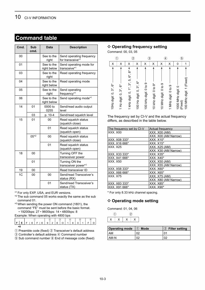
Command table
Cmd. Subcmd.
Data Description
00 See to the right
Send operating frequency for transceive*1
01 See to the right below
Send operating mode for transceive*1
03 See to the right
Read operating frequency
04 See to the right below
Read operating mode
05 See to the right
Send operating frequency*1
06 See to the right below
Send operating mode*1
14 01 0000 to 0255
Send/read audio output level
03 p. 10-4 Send/read squelch level15 01 00 Read squelch status
(squelch close)01 Read squelch status
(squelch open)05*2 00 Read squelch status
(squelch close)01 Read squelch status
(squelch open)18 00 Turning OFF the
transceiver power01 Turning ON the
transceiver power*3
19 00 Read transceiver ID1C 00 00 Send/read Transceiver’s
status (RX)01 Send/read Transceiver’s
status (TX)
*1 For only EXP, USA, and EUR versions.*2 The sub command 05 works exactly the same as the sub
command 01.*3 When sending the power ON command (1801), the
command “FE” must be sent before the basic format. • 19200bps: 27 • 9600bps: 14 • 4800bps: 8Example: When operating with 4800 bps
q w e r t y
FF E×8
29EFE E 1081O DF
q Preamble code (fixed) w Transceiver’s default addresse Controller’s default address r Command numbert Sub command number y End of message code (fixed)
D Operating frequency settingCommand: 00, 03, 05
q
XX X X X
w e
X
r t
XX 10
10H
z di
git:
0, 3
*, 6
*
1 H
z di
git:
0, 3
*, 6
*
1 kH
z di
git:
0, 1
*, 3
*, 5
, 6*,
8*
100
Hz
digi
t: 0,
3*,
6*
100
kHz
digi
t: 0
to 9
10 k
Hz
digi
t: 0
to 9
*
10 M
Hz
digi
t: 0
to 9
1 M
Hz
digi
t: 0
to 9
1000
MH
z di
git:
0(F
ixed
)10
0 M
Hz
digi
t: 1
(Fix
ed)
X X X 0
q w
1kHz桁:0~3
100Hz桁:0~9
10Hz桁:0~9
1Hz桁:0
(固定)
X X 0 X X X
q* w e
0 (f
ixed
)F
irst d
igit:
0~
7S
econ
d di
git:
0~7
Thi
rd d
igit:
0~
7
Receive polarity: 0: Normal 1: ReverseTransmit polarity: 0: Normal 1: Reverse
The frequency set by CI-V and the actual frequency differs, as described in the table below.
The frequency set by CI-V Actual frequencyXXX. X00 XXX. X00 (AM)
XXX. X00 (AM Narrow)XXX. X08 333* XXX. X10*XXX. X16 666* XXX. X15*XXX. X25 XXX. X25 (AM)
XXX. X30 (AM Narrow)XXX. X33 333* XXX. X35*XXX. X41 666* XXX. X40*XXX. X50 XXX. X50 (AM)
XXX. X55 (AM Narrow)XXX. X58 333* XXX. X60*XXX. X66 666* XXX. X65*XXX. X75 XXX. X75 (AM)
XXX. X80 (AM Narrow)XXX. X83 333* XXX. X85*XXX. X91 666* XXX. X90*
* For only 8.33 kHz channel spacing.
D Operating mode setting
Command: 01, 04, 06
q
XX X X
w
Operating mode q Mode w Filter settingAM 02 01AM-N 02 02

10 CI-V INFORMATION
10-4
D Squelch setting
Command: 1403
OFF 1 2 3 40000–0009 0010–0019 0020–0030 0031–0040 0041–0050
5 6 7 8 90051–0060 0061–0071 0072–0081 0082–0091 0092–0101
10 11 12 13 140102–0112 0113–0122 0123–0132 0133–0142 0143–0153
15 16 17 18 190154–0163 0164–0173 0174–0183 0184–0194 0195–0204
20 21 22 23 240205–0214 0215–0224 0225–0235 0236–0245 0246–0255
Command table (Continued)

INDEX
10-5
NNoise limiting .......................................................... 7-5
OOne-touch PTT ....................................................... 7-8On-hook scan ......................................................... 3-2Options ................................................................... 9-3
PPassword ................................................................ 2-2Power save ............................................................. 7-8Priority channel ................................................5-2, 7-5Priority scan ............................................................ 3-2PTT beep ................................................................ 7-8
RReceiving ................................................................ 2-2
SScan resume timer ................................................. 7-6Scan types .............................................................. 3-2Speaker selection ................................................... 7-7Specifications ......................................................... 9-2Squelch................................................................... 2-3Stop/TX channel ..................................................... 7-6
TTime-out timer ........................................................ 7-5Transmitting ............................................................ 2-2Turning ON the transceiver .................................... 2-2
UUT-133A Information............................................... 7-9
AAccessories, supplied ............................................. 8-4AF output ................................................................ 6-3
BBeep Level.............................................................. 7-7Bluetooth Bluetooth function ............................................... 7-8 Bluetooth headset use ........................................ 7-8 Bluetooth operation ............................................. 6-2 Device Search..................................................... 7-4 Disconnecting ..................................................... 6-4 Pairing ................................................................. 6-3 Pairing list ........................................................... 7-4 Pairing standby ................................................... 7-4 Unpairing............................................................. 6-4
CChannel spacing ..................................................... 7-5CI-V Address ............................................................... 7-6 Baud rate ............................................................ 7-6 Command table.................................................. 10-3 Data format ........................................................ 10-2 Transceive .......................................................... 7-6Connection Auto connect ....................................................... 7-8 Rear panel .......................................................... 8-2
DData device setting ................................................. 7-9Device initialize ....................................................... 7-9Dualwatch ............................................................... 5-2
EElectromagnetic interference .................................. 6-2
FFirmware version .................................................... 7-9Front panel ............................................................. 1-2
GGroup ..................................................................... 7-3Group name.....................................................7-3, 7-4
HHeadset setting....................................................... 7-8
KKey beep ................................................................ 7-7
LLCD backlight ......................................................... 7-7LCD contrast........................................................... 7-7Lock function .......................................................... 7-6Lockout channel ..............................................7-3, 7-4
MMain screen, indication type ................................... 7-7Memory channel ..................................................... 4-2 Deleting .............................................................. 4-2 Editing ................................................................. 4-2 Entering frequency ............................................. 4-3 Overwrite ............................................................ 7-4Memory mode......................................................... 2-2Menu mode, using .................................................. 7-2MIC key customize ................................................. 7-5Mounting the transceiver ........................................ 8-3

1-1-32 Kamiminami, Hirano-ku, Osaka 547-0003, JapanA-7249-3EX-qa© 2015–2016 Icom Inc.