iC-2710h INSTRUCTION MANUAL - RigPix Database - …rigpix.com/icom/ic2710h_manual.pdfSAVE THIS...
88
INSTRUCTION MANUAL iC-2710h DUAL BAND FM TRANSCEIVER
Transcript of iC-2710h INSTRUCTION MANUAL - RigPix Database - …rigpix.com/icom/ic2710h_manual.pdfSAVE THIS...

INSTRUCTION MANUAL
iC-2710hDUAL BAND FM TRANSCEIVER
IC-2710H.qxd 02.2.8 16:55 Page A (1,1)
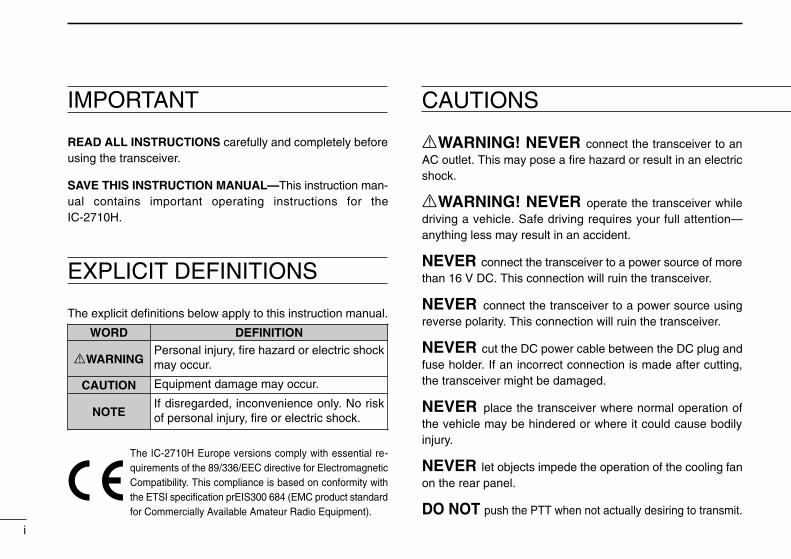
RWARNING! NEVER connect the transceiver to anAC outlet. This may pose a fire hazard or result in an electricshock.
RWARNING! NEVER operate the transceiver whiledriving a vehicle. Safe driving requires your full attention—anything less may result in an accident.
NEVER connect the transceiver to a power source of morethan 16 V DC. This connection will ruin the transceiver.
NEVER connect the transceiver to a power source usingreverse polarity. This connection will ruin the transceiver.
NEVER cut the DC power cable between the DC plug andfuse holder. If an incorrect connection is made after cutting,the transceiver might be damaged.
NEVER place the transceiver where normal operation ofthe vehicle may be hindered or where it could cause bodilyinjury.
NEVER let objects impede the operation of the cooling fanon the rear panel.
DO NOT push the PTT when not actually desiring to transmit.
i
IMPORTANT
READ ALL INSTRUCTIONS carefully and completely beforeusing the transceiver.
SAVE THIS INSTRUCTION MANUAL—This instruction man-ual contains important operating instructions for theIC-2710H.
EXPLICIT DEFINITIONS
The explicit definitions below apply to this instruction manual.
CAUTIONS
WORD DEFINITION
RWARNINGPersonal injury, fire hazard or electric shockmay occur.
CAUTION Equipment damage may occur.
NOTEIf disregarded, inconvenience only. No riskof personal injury, fire or electric shock.
The IC-2710H Europe versions comply with essential re-quirements of the 89/336/EEC directive for ElectromagneticCompatibility. This compliance is based on conformity withthe ETSI specification prEIS300 684 (EMC product standardfor Commercially Available Amateur Radio Equipment).
IC-2710H.qxd 02.2.8 16:55 Page i (1,1)
ii
UNPACKING
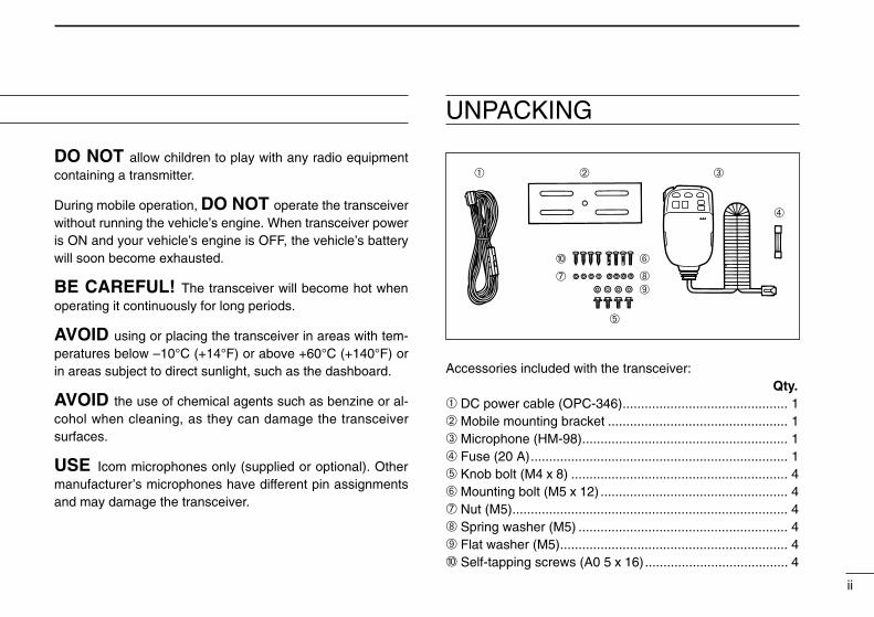
Accessories included with the transceiver:Qty.
➀ DC power cable (OPC-346)............................................. 1➁ Mobile mounting bracket ................................................. 1➂ Microphone (HM-98)........................................................ 1➃ Fuse (20 A)...................................................................... 1➄ Knob bolt (M4 x 8) ........................................................... 4➅ Mounting bolt (M5 x 12) ................................................... 4➆ Nut (M5)........................................................................... 4➇ Spring washer (M5) ......................................................... 4➈ Flat washer (M5).............................................................. 4➉ Self-tapping screws (A0 5 x 16)....................................... 4
DO NOT allow children to play with any radio equipmentcontaining a transmitter.
During mobile operation, DO NOT operate the transceiverwithout running the vehicle’s engine. When transceiver poweris ON and your vehicle’s engine is OFF, the vehicle’s batterywill soon become exhausted.
BE CAREFUL! The transceiver will become hot whenoperating it continuously for long periods.
AVOID using or placing the transceiver in areas with tem-peratures below –10°C (+14°F) or above +60°C (+140°F) orin areas subject to direct sunlight, such as the dashboard.
AVOID the use of chemical agents such as benzine or al-cohol when cleaning, as they can damage the transceiversurfaces.
USE Icom microphones only (supplied or optional). Othermanufacturer’s microphones have different pin assignmentsand may damage the transceiver.
➀ ➁ ➂
➃
➄
➅➉
➆ ➇➈
IC-2710H.qxd 02.2.8 16:55 Page ii (1,1)

TABLE OF CONTENTS
iii
IMPORTANT .................................................................................... iEXPLICIT DEFINITIONS ................................................................. iCAUTIONS ...................................................................................... iUNPACKING ................................................................................... iiTABLE OF CONTENTS ................................................................. iii
1 PANEL DESCRIPTION ....................................................... 1 – 8 Front panel ........................................................................................... 1 Function display ................................................................................... 3 Rear panel ............................................................................................ 5 Microphone .......................................................................................... 6 Microphone keypad .............................................................................. 7
2 INSTALLATION ................................................................. 9 – 14 Installation methods ............................................................................. 9 Location .............................................................................................. 10 Single body installation ...................................................................... 10 Microphone connection ...................................................................... 11 Separate installation ........................................................................... 11 Optional MB-58 installation ................................................................ 12 Battery connection ............................................................................. 13 DC power supply connection ............................................................. 13 Antenna installation ............................................................................ 14
3 SETTING A FREQUENCY .............................................. 15 – 19 Preparation ......................................................................................... 15 Lock functions .................................................................................... 16 Using a tuning dial .............................................................................. 17 Using [Y]/[Z] switches ....................................................................... 17 Tuning step selection ......................................................................... 18 Using the keypad ............................................................................... 19
4 BASIC OPERATION ....................................................... 20 – 26
Receiving ........................................................................................... 20 Monitor function .................................................................................. 21 Audio mute function ........................................................................... 21 Avionics band receive ........................................................................ 21 Sub band access ................................................................................ 22 Sub band mute/sub band busy beep ................................................. 23 Para-watch ......................................................................................... 24 Transmitting ........................................................................................ 25 Selecting the output power ................................................................. 25 Crossband full duplex ......................................................................... 26 One-touch PTT function ..................................................................... 26
5 REPEATER OPERATION ............................................... 27 – 31 Operation ........................................................................................... 27 Subaudible tones ............................................................................... 29 Offset frequency ................................................................................. 30 Auto repeater ..................................................................................... 31
6 MEMORY OPERATION .................................................. 32 – 36 General description ............................................................................ 32 Memory channel selection ................................................................. 32 Programming a memory channel ....................................................... 33 Programming a memory channel via the microphone .......................... 34 Transferring memory contents ........................................................... 35 Memory clearing ................................................................................. 36
7 CALL CHANNEL OPERATION ...................................... 37 – 38 Calling up a call channel contents ...................................................... 37 Transferring call channel contents ..................................................... 37 Programming a call channel ............................................................... 38
8 SCRATCH PAD MEMORY .............................................. 39 – 40 What is a scratch pad memory? ......................................................... 39
IC-2710H.qxd 02.2.8 16:55 Page iii (1,1)

iv
Calling up a scratch pad memory ....................................................... 39 Transferring scratch pad memory contents ........................................ 40
9 SCAN OPERATION ........................................................ 41 – 46 Scan types ......................................................................................... 41 Start/stop scan ................................................................................... 42 Programming scan edges .................................................................. 43 Programming scan edges via the microphone ................................... 44 Skip channel setting ........................................................................... 45 Scan resume condition ....................................................................... 46
10 PRIORITY WATCH .......................................................... 47 – 48 Priority watch types ............................................................................ 47 Priority watch operation ...................................................................... 48
11 DTMF MEMORY ENCODER .......................................... 49 – 52 Programming a DTMF code ............................................................... 49 Clearing the DTMF memory contents ................................................ 49 Programming a DTMF code via the microphone ............................... 50 Transmitting a DTMF code ................................................................. 51 DTMF speed ...................................................................................... 52
12 POCKET BEEP AND TONE SQUELCH ........................ 53 – 55 Pocket beep operation ....................................................................... 53 Tone squelch operation ...................................................................... 54 Tone scan ........................................................................................... 55
13 PAGER AND CODE SQUELCH ..................................... 56 – 62 Pager function .................................................................................... 56 Code channels ................................................................................... 57 Code programming ............................................................................ 58 Pager operation .................................................................................. 59 Code squelch function ........................................................................ 61 Code squelch operation ..................................................................... 62
14 EXTERNAL DTMF REMOTE .......................................... 63 – 64
15 OPTIONAL UNIT INSTALLATION ......................................... 65 Optional unit installation ..................................................................... 65
16 WIRELESS OPERATION ................................................ 66 – 71 Connection ......................................................................................... 66 HM-90 WIRELESS MICROPHONE ............................................................ 66 EX-1759 installation ........................................................................... 67 HM-90 switches .................................................................................. 68 Microphone address ........................................................................... 71
17 OTHER FUNCTIONS ...................................................... 72 – 74 Beep tones on/off ............................................................................... 72 Time-out timer .................................................................................... 72 Auto power-off .................................................................................... 73 Cooling fan setting ............................................................................. 73 Microphone [F-1]/[F-2] keys ............................................................... 74 Display dimmer setting ....................................................................... 74 Demonstration display ........................................................................ 74
18 MAINTENANCE .............................................................. 75 – 77 Troubleshooting .................................................................................. 75 Fuse replacement .............................................................................. 77 Partial resetting .................................................................................. 77 Total resetting ..................................................................................... 77
19 SPECIFICATIONS .................................................................. 78
20 OPTIONS ........................................................................ 79 – 80
21 MODE ARRANGEMENT CHART ................................... 81 – 82
IC-2710H.qxd 02.2.8 16:55 Page iv (1,1)

PANEL DESCRIPTION1
1
q POWER SWITCH [POWER]Turns power ON and OFF when pushed for 1 sec.
w TUNING DIALS Select the operating frequency (p. 17), the memory
channel (p. 32), the contents of the set mode display(p. 82) and the scanning direction. (p. 42)
Select the main band when pushed. (p. 15) When the sub band is selected, activate the sub band
function when pushed and held. (p. 22) When the main band is selected, change the operating
band (for para watch) when pushed and held. (p. 24)
e SQUELCH CONTROLS [SQL(MONI)] Vary the squelch level. (p. 20)
• RF attenuator activates and increases the attenuation whenrotated clockwise to the center position and further.
Toggles squelch opened and closed when pushed.• Transmit frequency is automatically selected when squelch
opens.
r VOLUME CONTROLS [VOL(SET L)]/[VOL(SET D)] Adjust the audio levels. (p. 20) Select set mode when pushed. (p. 82) Toggles the lock function ON/OFF when pushed and
held [SET(L)]. (p. 16) Allows you to adjust the display brightness when
pushed and held [SET(D)]. (p. 74)
V MHzSCAN
S.MW MW
LOW DUP POWER DTMF TMONI
SQL
MONI
SQL
SET L
VOL
SET D
VOL
M CALL PRIO
V MHz SCAN
S.MW MW
M CALLPRIO
LOCK
VFO
CALL
MR
SUB
BAND
F-2
F-1
Function display (p. 3)
Front panel (remote controller)
IC-2710H.qxd 02.2.8 16:55 Page 1 (1,1)
1PANEL DESCRIPTION
2
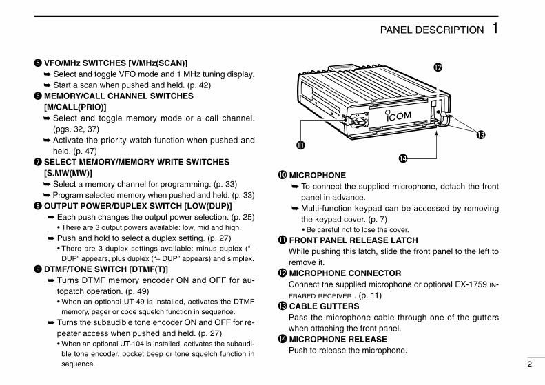
t VFO/MHz SWITCHES [V/MHz(SCAN)] Select and toggle VFO mode and 1 MHz tuning display. Start a scan when pushed and held. (p. 42)
y MEMORY/CALL CHANNEL SWITCHES[M/CALL(PRIO)] Select and toggle memory mode or a call channel.
(pgs. 32, 37) Activate the priority watch function when pushed and
held. (p. 47)u SELECT MEMORY/MEMORY WRITE SWITCHES
[S.MW(MW)] Select a memory channel for programming. (p. 33) Program selected memory when pushed and held. (p. 33)
i OUTPUT POWER/DUPLEX SWITCH [LOW(DUP)] Each push changes the output power selection. (p. 25)
• There are 3 output powers available: low, mid and high.
Push and hold to select a duplex setting. (p. 27)• There are 3 duplex settings available: minus duplex (“–
DUP” appears, plus duplex (“+ DUP” appears) and simplex.
o DTMF/TONE SWITCH [DTMF(T)] Turns DTMF memory encoder ON and OFF for au-
topatch operation. (p. 49)• When an optional UT-49 is installed, activates the DTMF
memory, pager or code squelch function in sequence.
Turns the subaudible tone encoder ON and OFF for re-peater access when pushed and held. (p. 27)• When an optional UT-104 is installed, activates the subaudi-
ble tone encoder, pocket beep or tone squelch function insequence.
!0 MICROPHONE To connect the supplied microphone, detach the front
panel in advance. Multi-function keypad can be accessed by removing
the keypad cover. (p. 7)• Be careful not to lose the cover.
!1 FRONT PANEL RELEASE LATCHWhile pushing this latch, slide the front panel to the left toremove it.
!2 MICROPHONE CONNECTORConnect the supplied microphone or optional EX-1759 IN-FRARED RECEIVER . (p. 11)
!3 CABLE GUTTERSPass the microphone cable through one of the gutterswhen attaching the front panel.
!4 MICROPHONE RELEASEPush to release the microphone.
IC-2710H.qxd 02.2.8 16:55 Page 2 (1,1)

1 PANEL DESCRIPTION
3
q SUB BAND ACCESS INDICATORS (p. 22)Appear when the sub band access function is activatedand indicate the function control band via the microphoneand some front panel switches (except transmitting).
w MAIN BAND INDICATORS (p. 15)Indicate the main band for transmit and function control.
e TRANSMIT INDICATORS (p. 25) Appear while transmitting. Flash while transmitting with the one-touch PTT func-
tion (p. 26).r FREQUENCY READOUTS
Show the operating frequency, set mode contents, etc.• The decimal point of the frequency flashes while scanning.
(p. 42)
• “d” appears in place of the 100 MHz while the DTMF memoryfunction is in use; when optional units are installed, “P,” or “C”appears in place of the 100 MHz while the pager or codesquelch functions are in use, respectively. (pgs. 49, 59, 61)
t DUPLEX INDICATORS (p. 27)“DUP–” or “DUP” appear during semi-duplex operation (re-peater operation).
y TONE INDICATORS “T” appears while the subaudible tone encoder is in
use. (p. 27) “T SQL” appears while the optional tone squelch func-
tion is in use. (p. 54) “T SQLS” appears while the optional pocket beep
function is in use. (p. 53)
BUSYLOW LOW
MUTE
PR I O
DUP
SKIP SKIPBUSY
MUTE
PR I O
– T SQL DUP – T SQLTOT
A O
REMO
q
w e r t y u i
o
!0
!1
q
o
!0
!1
!2!3!4!5!6 !2!3!4!5!6!7
wert y
Function display
IC-2710H.qxd 02.2.8 16:55 Page 3 (1,1)
4
1PANEL DESCRIPTION
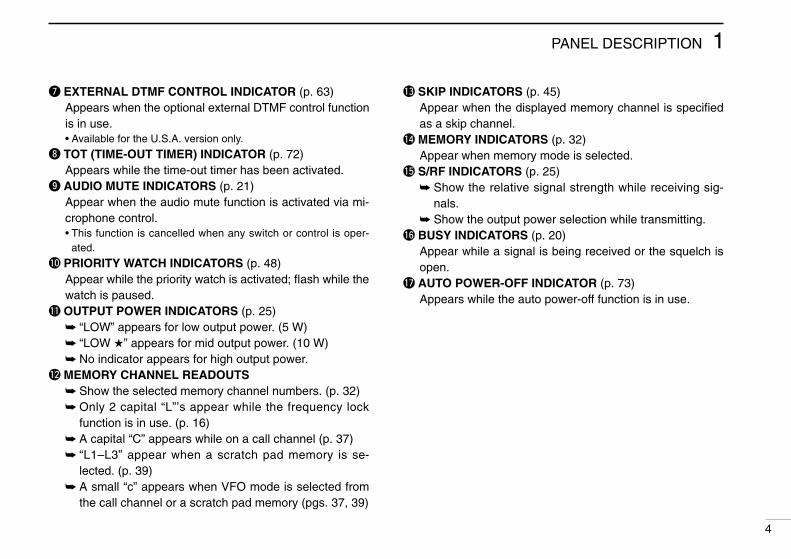
u EXTERNAL DTMF CONTROL INDICATOR (p. 63)Appears when the optional external DTMF control functionis in use.• Available for the U.S.A. version only.
i TOT (TIME-OUT TIMER) INDICATOR (p. 72)Appears while the time-out timer has been activated.
o AUDIO MUTE INDICATORS (p. 21)Appear when the audio mute function is activated via mi-crophone control.• This function is cancelled when any switch or control is oper-
ated.
!0 PRIORITY WATCH INDICATORS (p. 48)Appear while the priority watch is activated; flash while thewatch is paused.
!1 OUTPUT POWER INDICATORS (p. 25) “LOW” appears for low output power. (5 W) “LOW ” appears for mid output power. (10 W) No indicator appears for high output power.
!2 MEMORY CHANNEL READOUTS Show the selected memory channel numbers. (p. 32) Only 2 capital “L”’s appear while the frequency lock
function is in use. (p. 16) A capital “C” appears while on a call channel (p. 37) “L1–L3” appear when a scratch pad memory is se-
lected. (p. 39) A small “c” appears when VFO mode is selected from
the call channel or a scratch pad memory (pgs. 37, 39)
!3 SKIP INDICATORS (p. 45)Appear when the displayed memory channel is specifiedas a skip channel.
!4 MEMORY INDICATORS (p. 32)Appear when memory mode is selected.
!5 S/RF INDICATORS (p. 25) Show the relative signal strength while receiving sig-
nals. Show the output power selection while transmitting.
!6 BUSY INDICATORS (p. 20)Appear while a signal is being received or the squelch isopen.
!7 AUTO POWER-OFF INDICATOR (p. 73)Appears while the auto power-off function is in use.
IC-2710H.qxd 02.2.8 16:55 Page 4 (1,1)
1 PANEL DESCRIPTION
5
Rear panel
qw
e
r
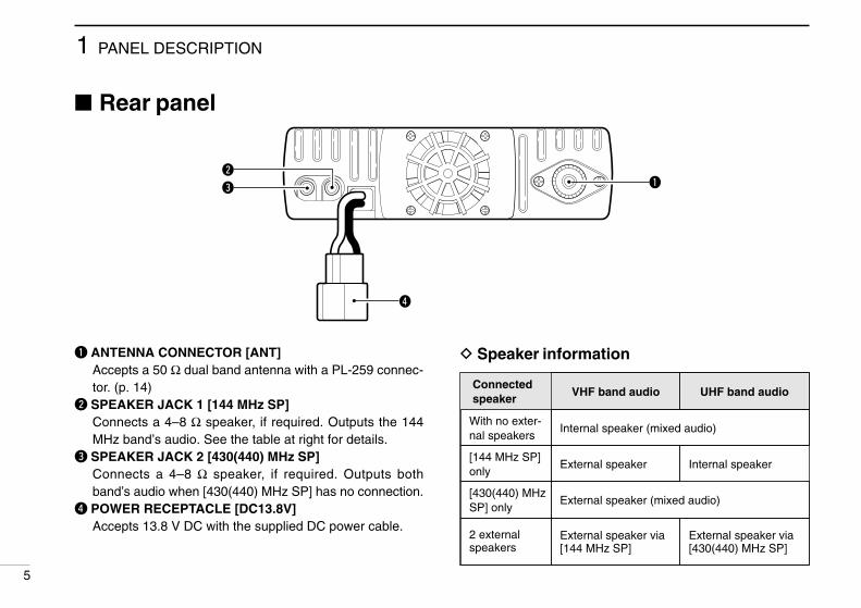
q ANTENNA CONNECTOR [ANT]Accepts a 50 Ω dual band antenna with a PL-259 connec-tor. (p. 14)
w SPEAKER JACK 1 [144 MHz SP]Connects a 4–8 Ω speaker, if required. Outputs the 144MHz band’s audio. See the table at right for details.
e SPEAKER JACK 2 [430(440) MHz SP]Connects a 4–8 Ω speaker, if required. Outputs bothband’s audio when [430(440) MHz SP] has no connection.
r POWER RECEPTACLE [DC13.8V]Accepts 13.8 V DC with the supplied DC power cable.
D Speaker information
Connectedspeaker
VHF band audio UHF band audio
With no exter-nal speakers
Internal speaker (mixed audio)
[144 MHz SP]only
External speaker
[430(440) MHzSP] only
External speaker (mixed audio)
2 externalspeakers
External speaker via[144 MHz SP]
External speaker via[430(440) MHz SP]
Internal speaker
IC-2710H.qxd 02.2.8 16:55 Page 5 (1,1)

1PANEL DESCRIPTION
6
Microphone
LOCK
VFO
CALL
MR
SUB
BAND
MW
FUNC
ACLR
D-OFF
BSET
PTT-M
3PRIO
DTMF
6LOW
AFC-OFF
2SCAN
CSQL
5MID
AFC
1MONI
PGR
4HIGH
T-OFF
CENT
TSQL
9SIMP
16KEY LOCK
#
TSQLS
8DUP+
TONE-2
0
TONE
7DUP
TONE-1
F-2
F-1
DTMF-S
MUTE
DSQLSQLVOLVOL
Mic element
q
w
e r t
y
u
i
o
q UP/DOWN SWITCHES [Y]/[Z] Push either switch to change the operating frequency,
memory channel, set mode contents, etc. (pgs. 17, 32) Push and hold either switch to start scanning. (p. 42)
w PTT SWITCH Push and hold to transmit; release to receive. (p. 25) Toggles between transmitting and receiving while the
one-touch PTT function is in use. (p. 26)e VFO SWITCH [VFO(LOCK)]
Push to select VFO mode. Push and hold to toggle the lock function ON and OFF.
r MEMORY SWITCH [MR(CALL)] Push to select memory mode. (p. 32) Push and hold to select the call channel. (p. 37)
t ACTIVITY INDICATORLights red while a key is pushed; lights green while theone-touch PTT function is in use.
y BAND SWITCH Push to toggle the main band. (p. 15) Push and hold to turn the sub band access function ON
and OFF. (p. 22)u FUNCTION SWITCHES [F-1]/[F-2] (p. 74)
Assign your desired key function from the front panelswitches.• Default settings are VHF and UHF tuning dials to [F-1] and [F-2],
respectively for quick band selection.
i FUNCTION INDICATOR Lights yellow while [FUNC] is activated—indicates the
secondary function of switches can be accessed. Lights green when [DTMF-S] is activated—DTMF sig-
nals can be transmitted with the keypad. (p. 51)o KEYPAD
Used for controlling the transceiver, transmitting a DTMFencoder, etc. See pgs. 7 and 8 for function details.
IC-2710H.qxd 02.2.8 16:55 Page 6 (1,1)
1 PANEL DESCRIPTION
7
Microphone keypad
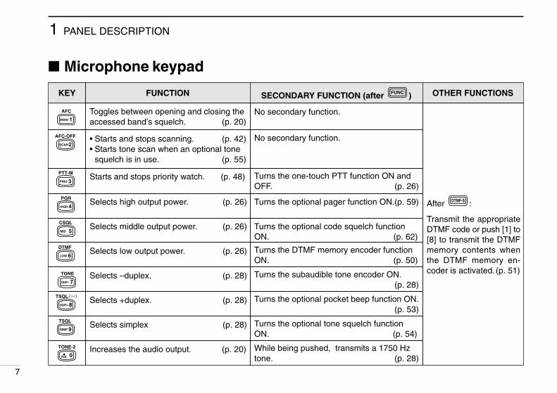
FUNCTION SECONDARY FUNCTION (after )FUNC OTHER FUNCTIONS
Toggles between opening and closing theaccessed band’s squelch. (p. 20)
No secondary function.
After :
Transmit the appropriateDTMF code or push [1] to[8] to transmit the DTMFmemory contents whenthe DTMF memory en-coder is activated. (p. 51)
DTMF-S
• Starts and stops scanning. (p. 42)• Starts tone scan when an optional tone
squelch is in use. (p. 55)
No secondary function.
Starts and stops priority watch. (p. 48) Turns the one-touch PTT function ON andOFF. (p. 26)
Selects high output power. (p. 26) Turns the optional pager function ON.(p. 59)
Selects middle output power. (p. 26) Turns the optional code squelch functionON. (p. 62)
Selects low output power. (p. 26) Turns the DTMF memory encoder functionON. (p. 50)
Selects –duplex. (p. 28) Turns the subaudible tone encoder ON.(p. 28)
Selects +duplex. (p. 28) Turns the optional pocket beep function ON.(p. 53)
Selects simplex (p. 28) Turns the optional tone squelch functionON. (p. 54)
Increases the audio output. (p. 20) While being pushed, transmits a 1750 Hztone. (p. 28)
AFC
1MONI
AFC-OFF
2SCAN
PTT-M
3PRIO
PGR
4HIGH
CSQL
5MID
DTMF
6LOW
TONE
7DUP–
TSQLS
8DUP+
TSQL
9SIMP
TONE-2
0VOL
KEY
IC-2710H.qxd 02.2.8 16:55 Page 7 (1,1)

1PANEL DESCRIPTION
8
KEY FUNCTION SECONDARY FUNCTION (after )FUNC OTHER FUNCTIONS
• Clears a digit before entry. (p. 19)• Cancels the scan, priority watch, pager,
code squelch or DTMF memory function.(pgs. 42, 48, 51, 59, 62)
• Writes the VFO contents into the memorychannel or call channel. (pgs. 34, 38)
• Advances the memory channel numberwhen continuously pushed after program-ming is completed. (p. 34)
After :
Transmit the appropriateDTMF code. (p. 51)
DTMF-S
Enters set mode and advances the setmode selection order. (p. 82)
Turns the pager, code squelch, DTMF mem-ory or DTMF remote function OFF.
(pgs. 59, 62, 63)
• Sets the keypad for numeral input.(p. 19)
• Decreases the set mode selection orderafter entering set mode. (p. 82)
Turns the subaudible tone encoder, pocketbeep or tone squelch OFF. (pgs. 28, 53, 54)
Increases the squelch level. (p. 20)• The [SQL] control on the front panel has prior-
ity when rotated.
Mutes both band’s audio signals. (p. 21)• Mute function is released when any operation is
performed.
Decreases the squelch level. (p. 20)• The [SQL] control on the front panel has prior-
ity when rotated.
Locks the digit keys on the keypad (includingthe A–D, # and M keys. (p. 16)
Decreases the audio output. (p. 20) Sends a 1750 Hz tone signal for 1 sec.(p. 28)
MW
ACLR
D-OFF
BSET
16KEY LOCK
#SQL
T-OFF
CENT
MUTE
DSQL
TONE-1
MVOL
IC-2710H.qxd 02.2.8 16:55 Page 8 (1,1)

D Separate installation
• Optional OPC-600 SEPARATION CABLE (3.5 m; 11.5 ft) orOPC-601 (7.0 m; 23.0 ft) is necessary.
• Optional MB-58 REMOTE CONTROLLER BRACKET is availablefor front panel mounting.
• Optional MB-65 MOUNTING BASE is available for increasingfront panel mounting possibilities (MB-58 is necessary).
• Optional OPC-440 MICROPHONE CABLE (5.0 m; 16.4 ft) andOPC-647 (2.5 m; 8.2 ft) are available to extend the micro-phone cable.
• Optional OPC-441 SPEAKER CABLE (5.0 m; 16.4 ft) is avail-able to extend the speaker cable.
INSTALLATION2
9
Installation methodsD Single body installation
• It is not necessary to purchase a mounting bracket. Thesupplied mounting bracket (or optional MB-17A) can beused for installation.
Main body
Front panel
IC-2710H.qxd 02.2.8 16:55 Page 9 (1,1)

2INSTALLATION
10
LocationSelect a location which can support the weight of the trans-ceiver and does not interfere with driving in any way. We rec-ommend the locations shown in the diagram below.
Single body installation➀ Drill 4 holes where the mounting bracket is to be installed.
• Approx. 5.5–6 mm (3⁄16 in) when using nuts; approx. 2–3 mm (1⁄16
in) when using self-tapping screws.
➁ Insert the supplied screws, nuts and washers through themounting bracket and tighten.
➂ Adjust the angle for the clearest view of the function dis-play.
NEVER place the transceiver or remote controller wherenormal operation of the vehicle may be hindered or whereit could cause bodily injury.NEVER place the transceiver or remote controller whereair bag deployment may be obstructed.DO NOT place the transceiver or remote controller wherehot or cold air blows directly onto it.AVOID placing the transceiver or remote controller in di-rect sunlight.
• EXAMPLE INSTALLATION LOCATIONS
20°
Mounting nut
Mountingbracket
When usingself-tappingscrews.
NutSpring washer
Flat washer
Flat washer
Springwasher
IC-2710H.qxd 02.2.8 16:55 Page 10 (1,1)

2 INSTALLATION
11
Microphone connectionThe microphone connector is located behind the front panel.Connect the supplied microphone as follows:
➀ Push the release button, then detach the remote controlleras shown below.
➁ Connect the supplied microphone to the microphone con-nector.
➂ Reattach the remote controller to the main body.➃ To remove the microphone, push the release button as
above.
Separate installationUsing an optional OPC-600/601 SEPARATION CABLE, the frontpanel can be separated from the main body, doubling as a re-mote controller.
➀ Detach the front panel as shown at left.➁ Connect a separation cable to the front panel and to the
main body using the supplied screws as illustrated below.
mic releasePush
Releasebutton
OPC-600 or OPC-601
Rear of front panel Main body
➀ 8 V OUT➁ Freq. up/down➂ 8 V control IN➃ PTT➄ Mic AF (–)➅ Mic AF (+)➆ Ground➇ Data IN
➇➀
Microphone pin assignments
IC-2710H.qxd 02.2.8 16:55 Page 11 (1,1)
2INSTALLATION
12
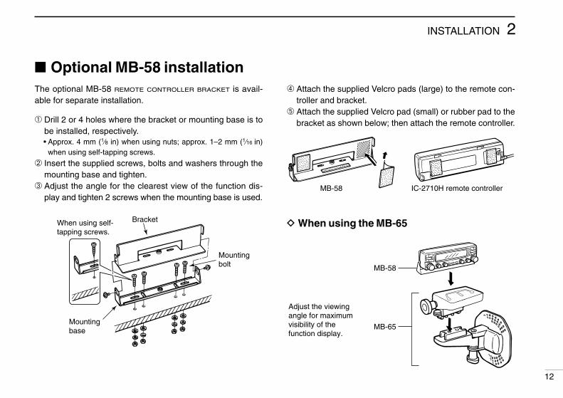
Optional MB-58 installationThe optional MB-58 REMOTE CONTROLLER BRACKET is avail-able for separate installation.
➀ Drill 2 or 4 holes where the bracket or mounting base is tobe installed, respectively.• Approx. 4 mm (1⁄8 in) when using nuts; approx. 1–2 mm (1⁄16 in)
when using self-tapping screws.
➁ Insert the supplied screws, bolts and washers through themounting base and tighten.
➂ Adjust the angle for the clearest view of the function dis-play and tighten 2 screws when the mounting base is used.
BracketWhen using self-tapping screws.
Mountingbase
Mountingbolt
➃ Attach the supplied Velcro pads (large) to the remote con-troller and bracket.
➄ Attach the supplied Velcro pad (small) or rubber pad to thebracket as shown below; then attach the remote controller.
D When using the MB-65
MB-58 IC-2710H remote controller
MB-58
MB-65
Adjust the viewing angle for maximum visibility of the function display.
IC-2710H.qxd 02.2.8 16:55 Page 12 (1,1)

2 INSTALLATION
13
Battery connection DC power supply connectionUse a 13.8 V DC power supply with more than 12 A capabil-ity. An optional IC-PS30 DC POWER SUPPLY is available forusing the transceiver with a DC power supply in your home.
Make sure the ground terminal of the DC power supply isgrounded.
NEVER connect the transceiver directly to a 24 V battery.DO NOT use the cigarette lighter socket for power con-nections.Attach a rubber grommet when passing the DC powercable through a metal plate to prevent short circuits.
• CONNECTING TO A DC POWER SOURCESee p. 77 for fuse replacement.
Fuses20 A
blackred⊕
red
Grommet
⊕
−
black−
12 VSuppliedDC power cable
• CONNECTING TO A DC POWER SUPPLYSee p.77 for fuse replacement.
DC powersupply 13.8 V
to anACoutlet
Fuses20 Ablack
red⊕−
⊕−
IC-2710H.qxd 02.2.8 16:55 Page 13 (1,1)
2INSTALLATION
14
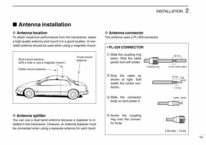
Antenna installationD Antenna locationTo obtain maximum performance from the transceiver, selecta high-quality antenna and mount it in a good location. A non-radial antenna should be used when using a magnetic mount.
D Antenna splitterYou can use a dual band antenna because a duplexer is in-stalled in the transceiver. However, an external duplexer mustbe connected when using a separate antenna for each band.
D Antenna connectorThe antenna uses a PL-259 connector.
30 mm
10 mm (soft solder)
10 mm
1–2 mm
solder solder
Softsolder
Coupling ring
• PL-259 CONNECTOR
➀
➂
➃
➁
Slide the coupling ring down. Strip the cable jacket and soft solder.
Slide the connector body on and solder it.
Screw the coupling ring onto the connec-tor body.
Strip the cable as shown at right. Soft solder the center con-ductor.
(10 mm ≈ 3⁄8 in)
Roof-mount antenna(Drill a hole or use a magnetic mount.)
Gutter-mount antenna
Trunk-mountantenna
IC-2710H.qxd 02.2.8 16:55 Page 14 (1,1)

SETTING A FREQUENCY3
15
PreparationD Turning power ONPush [POWER] for 1 sec. to turn power ON.
D Main bandThe IC-2710H can receive 144 MHz and 430(440) MHz bandsignals simultaneously. Function access or frequencychanges affect the main band only. In addition, signals canbe transmitted on the main band only. Set the desired bandas the main band.
Push the desired band’s tuning dial to select the main band.• “Q” indicates the main band.
Push [BAND] to toggle the main band selectionbetween the 144 and 430(440) MHz bands.
D VFO and memory modesThe transeiver has 2 normal operating modes: VFO modeand memory mode. You can select VFO mode or memorymode independently on each band.
Push the desired band’s [V/MHz] to select VFO mode whenthe transceiver is not in VFO mode.• If VFO mode is already selected, the digits below 100 kHz disap-
pear. In this case, push [V/MHz] again (or push twice depending onversion).
Push [VFO] to select VFO mode.• The microphone controls the main band only (or using
sub band access; p. 22). Push [BAND] to toggle themain band, then push [VFO], if necessary.
Push [POWER] for 1 sec.
BAND
Indicates memory modeVFO mode is selected
VFO
IC-2710H.qxd 02.2.8 16:55 Page 15 (1,1)

3SETTING A FREQUENCY
16
Lock functionsTo prevent accidental frequency changes and unnecessaryfunction access, use the lock function. The transceiver has 2different lock functions.
D Frequency lockThis function locks the tuning dials and switches electronicallyand can be used together with the microphone lock function.
Push and hold [(SET)L] until “L” appears in the memory chan-nel readout to activate the function.• To cancel the function, push and hold [(SET)L] until “L” disappears.• [PTT], [BAND], [MONI], [MUTE], [VOL] and [SQL] can be used while
the frequency lock function is in use. Also, DTMF tones or DTMFmemory contents can be transmitted from the microphone.
Push and hold [(VFO)LOCK] for 1 sec. to togglethe function ON and OFF.
D Microphone keypad lockThis function locks the microphone keypad.
Push [FUNC] then [A16 KEYLOCK] to togglethe microphone keypad lock function ON andOFF.• [PTT] and the 7 keys on the upper half of the mi-
crophone can be used.• All switches on the transceiver can be used.• The keypad lock function is released when the
power is turned OFF then ON again.
2 “L”s appear while the frequency lock functionis in use.
16 KEY LOCK#
LOCK
IC-2710H.qxd 02.2.8 16:55 Page 16 (1,1)

3 SETTING A FREQUENCY
17
Using a tuning dial➀ Rotate the desired band’s tuning dial to set the frequency.
• If VFO mode is not selected, push the same band’s [V/MHz] toselect VFO mode.
• Frequency changes according to the selected tuning steps.(p. 18)
➁ For the 1 MHz frequency setting, rotate the same band’stuning dial after pushing [V/MHz].• Pushing [V/MHz] for 1 sec. starts a scan function. If this happens,
push [V/MHz] again to stop the scan.
D 10 MHz stepsSome versions have 10 MHz tuning steps. For these versionsthe [V/MHz] switch selects 10 MHz, 1 MHz then kHz steps insequence.
Using [Y]/[Z] switchesPush [Y] or [Z] to set the main band’s frequency.• If VFO mode is not selected, push [VFO] to select it.• Frequency changes according to the selected tuning
steps. (p. 18)• Pushing [Y] or [Z] for more than 0.5 sec. activates a
scan. If this happens, push [Y] or [Z] again to stop it.
NOTE: 1 MHz steps cannot be used via the [Y]/[Z]switches
The display shows that the 1 MHz tuning step isselected for the VHF band.
YZ
5 9
IC-2710H.qxd 02.2.8 16:55 Page 17 (1,1)
3SETTING A FREQUENCY
18
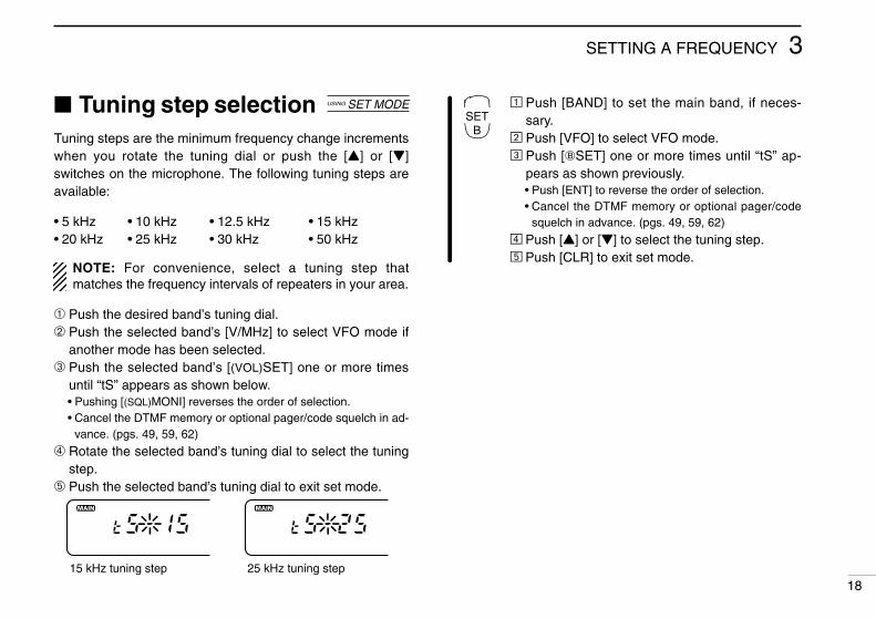
Tuning step selectionTuning steps are the minimum frequency change incrementswhen you rotate the tuning dial or push the [Y] or [Z]switches on the microphone. The following tuning steps areavailable:
• 5 kHz • 10 kHz • 12.5 kHz • 15 kHz• 20 kHz • 25 kHz • 30 kHz • 50 kHz
NOTE: For convenience, select a tuning step thatmatches the frequency intervals of repeaters in your area.
➀ Push the desired band’s tuning dial.➁ Push the selected band’s [V/MHz] to select VFO mode if
another mode has been selected.➂ Push the selected band’s [(VOL)SET] one or more times
until “tS” appears as shown below.• Pushing [(SQL)MONI] reverses the order of selection.• Cancel the DTMF memory or optional pager/code squelch in ad-
vance. (pgs. 49, 59, 62)
➃ Rotate the selected band’s tuning dial to select the tuningstep.
➄ Push the selected band’s tuning dial to exit set mode.
Ä Push [BAND] to set the main band, if neces-sary.
Å Push [VFO] to select VFO mode.Ç Push [FSET] one or more times until “tS” ap-
pears as shown previously.• Push [ENT] to reverse the order of selection.• Cancel the DTMF memory or optional pager/code
squelch in advance. (pgs. 49, 59, 62)
É Push [Y] or [Z] to select the tuning step.Ñ Push [CLR] to exit set mode.
USING SET MODE
25 kHz tuning step15 kHz tuning step
SETB
IC-2710H.qxd 02.2.8 16:55 Page 18 (1,1)

3 SETTING A FREQUENCY
19
Using the keypadThe frequency can be directly set via numeralkeys on the microphone.
Ä Push [BAND] to set the main band, if necessary.Å Push [VFO] to select VFO mode.Ç Push [ENT] to activate the keypad for digit input.
É Push 5 keys to input a frequency.• When a digit is mistakenly input, push [ENT] to clear the input,
then input from the 1st digit.• Pushing [CLR] clears input digits and retrieves the frequency.
Ñ Push [Y] or [Z] to make adjustments below the 10 kHzdigit, if desired.
ENTC
[EXAMPLE]: Setting the frequency to 145.360 MHz.
[EXAMPLE]: Setting the frequency to 446.325 MHz. (When the 25 kHz tuning step is selected in UHF.)
BAND then VFO CENT 3PRIO5MID1MONI 4HIGH 6LOW
BAND then VFO CENT 3PRIO6LOW4HIGH 4HIGH 0VOL
IC-2710H.qxd 02.2.8 16:55 Page 19 (1,1)

BASIC OPERATION 4
20
ReceivingThe IC-2710H can receive 144 MHz and 430(440) MHz bandsignals simultaneously.
➀ Push [POWER] for 1 sec. to turn power ON.➁ Set the audio levels.
Push [(SQL)MONI] to open the squelch. Rotate the [VOL] control to adjust the audio output level. Push [(SQL)MONI] again to close the squelch.
➂ Set the squelch levels. Rotate [SQL] fully counterclockwise in advance. Rotate [SQL] clockwise until the noise just disappears. When interference is received, rotate [SQL] clockwise
again for attenuator operation.➃ Set the operating frequency. (pgs. 15–19)➄ When receiving a signal on the set frequency, squelch
opens and the transceiver emits audio.• “BUSY” appears and the S/RF indicator shows the relative signal
strength on the received band.
BUSY1 5 9
When receiving a signal on VHF.
The volume and squelch levels can be adjusted via the mi-crophone. However, levels return to the front panel settingwhen power is turned OFF or a front panel control is adjusted.
Ä Push [POWER] on the transceiver for 1 sec. toturn power ON.
Å Set the audio levels. Select the desired band. Push [➀MONI], then push [BZVOL] or
[IYVOL] to adjust the audio level. Push [➀MONI] again to close the squelch.
Ç Set the squelch level using [AZSQL] or[HYSQL], if desired.
É Set the operating frequency. (pgs. 15–19)
CONVENIENTRF attenuator: The transceiver has an RF attenuator relatedto the [SQL] setting. The attenuator is automatically activatedwhen [SQL] is rotated further than the 12 o’clock position.Approx. 10 dB attenuation is obtained at full rotation.
BAND
VOL
VOL
Appears while setting volume Appears while setting squelch
BUSY1 1
IC-2710H.qxd 02.2.8 16:55 Page 20 (1,1)

4 BASIC OPERATION
21
Avionics band receive (U.S.A. version only)
AM mode can be selected over the range of 118.000 to135.995 MHz for reception of avionics-related broadcasts.
Push and hold [(SQL)MONI] to toggle between AM and FMmodes.• Mode selection cannot be performed via the microphone.
NOTE: The avionics band can be selected in the left bandonly, even when the para watch fuinction is in use.
CONVENIENTThe tuning steps for the avionics band are available sepa-rately from those for other ranges.
1 5 9
Appears when AMmode is selected.
Monitor functionThis function is used to listen to weak signals without disturb-ing the squelch setting or to open the desired band’s squelchmanually even when the optional mute functions such as tonesquelch, pager functions, etc., are in use.
Push the desired band’s [MONI] to open the desired band’ssquelch.• Push [MONI] again to cancel the function.• While duplex is ON for repeater operation, the transmitting fre-
quency can be monitored with [MONI].
Ä Push [BAND] to change bands, if necessary.Å Push [➀MONI] to open the main band’s
squelch.• Push [➀MONI] again to cancel the function.
Audio mute functionThis function mutes both band’s audio signalswithout disturbing the volume settings.
Ä Push [FUNC] then [HMUTE] to mute both band’s audio signals.• “MUTE” appears for both bands.
Å Push [ECLR] (or any other key) to cancel the function.• “MUTE” disappears.
MONI➀
MUTEH
IC-2710H.qxd 02.2.8 16:55 Page 21 (1,1)

4BASIC OPERATION
22
Sub band accessThis function allows you to change sub band settings such asduplex settings, especially useful from the microphone, duringtransmission standby on the main band.
It’s easy to access the sub band and return to the main bandwith the band switch.
➀ Push and hold the sub band’s tuning dial until “^” ap-pears as shown below.• If the [PTT] is pushed at this time, transmit is on the main band.• If the main band’s tuning dial is mistakenly pushed and held, the
para-watch function is activated. In this case, push the mainband’s tuning dial for 1 sec. and repeat ➀ again. (p. 24)
➁ Activate functions such as duplex setting, subaudibletones, etc.
➂ To exit sub band access, push the main band’s tuning dial.• To switch from the sub band to the main band, push the sub
band’s tuning dial.• Pushing and holding the sub band’s tuning dial until “^” dis-
appears also exits sub band access.
The sub band access function is also available from the mi-crophone and is useful for setting the sub band’s frequency,etc. during transmission standby on the main band.
Ä Push and hold [(BAND)SUB].• “^” appears.• If the [PTT] is pushed at this time, transmit is on the
main band.
Å Set the sub band’s operating frequency or acti-vate functions.
Ç To exit sub band access, push and hold[(BAND)SUB] again.• “^” disappears.• To switch from the sub band to the main band (for
transmitting), push [(BAND)SUB] (momentarily).
“^” appears
BAND
IC-2710H.qxd 02.2.8 16:55 Page 22 (1,1)

4 BASIC OPERATION
23
Sub band mute/sub band busy beep
The sub band mute function automatically cuts out sub bandAF signals when both main and sub band signals are re-ceived simultaneously.
The sub band busy beep sounds when the sub band’ssquelch is closed to inform you that the sub band’s squelchhas been opened.
➀ While pushing [(VOL)SET L] (on the left side of the trans-ceiver), push [POWER] to enter initial set mode.
➁ Push [SET] one or more times until “Sub” appears in thedisplay as shown above.• Push [MONI] to reverse the order of selection.
USING INITIAL SET MODE
The display shows that the sub band mute is turned ON and the sub band busy beep is turned OFF.
Common setting for each band
➂ Rotate the main band’s tuning dial to set the condition.
➃ Push [POWER] momentarily to exit initial set mode.
DISPLAY SUB BAND MUTE BUSY BEEPSub-oF OFF OFF
Sub-oF S OFF ONSub-on ON OFFSub-on S ON ON
IC-2710H.qxd 02.2.8 16:55 Page 23 (1,1)

4BASIC OPERATION
24
Para-watchThe IC-2710H can simultaneously receive 2 signals on thesame band, 144 MHz or 430(440) MHz band, using the para-watch function.
[EXAMPLE]
Can be switched between VHF and UHF.
➀ Push the desired band's tuning dial to assign the mainband.
➁ Push and hold the main band’s tuning dial until “-144-” or “-430-” (or “-440-” for U.S.A. version) appears to changethe operating band.
➂ Repeat step ➁ again to cancel the function.
NOTE: • Memory channels are common for the same band.• Transmitting on the para-watch frequency is possible and
the transmission quality is the same as usual. However,the opposite band’s audio is muted, even when bothbands are reversed.
The para-watch function cannot be activated fromthe regular microphone keys. However, when thetuning dial function is assigned to the user-pro-grammable keys, [F-1] and [F-2], the para-watchfunction can be activated via the microphone inthe same manner as described above.
F-1F-2
Receiving a VHF signal
IC-2710H.qxd 02.2.8 16:55 Page 24 (1,1)

4 BASIC OPERATION
25
Transmitting
NOTE: To prevent interference, listen on the frequency before
transmitting by pushing the main band’s [(SQL)MONI] orthe microphone’s [➀MONI].
To prevent howling and sensitivity rejection, AVOID set-ting the 430(440) MHz band frequency near a multipleof the 144 MHz band frequency, e.g. setting for145 MHz and 435 MHz.
➀ Push the desired band’s tuning dial to select the main bandfor transmitting.
➁ Set the operating frequency. (pgs. 15–19)• Select output power if desired. See section at right for details.
➂ Push and hold [PTT] to transmit.• “$” appears.• The S/RF indicator shows the output power selection.• The operating frequency, etc. are automatically programmed into
a scratch pad memory. See p. 39 for details.• One-touch PTT function is available. See p. 26 for details.
➃ Speak into the microphone using your normal voice level.• DO NOT hold the microphone too close to your mouth or speak
too loudly. This may distort the signal.
➄ Release [PTT] to return to receive.
Selecting the output powerThe transceiver has 3 output power levels to suit your oper-ating requirements. Lower output power during short-distancecommunication may reduce interference to other stations andreduces current consumption.
➀ Push the desired band’s tuning dial.➁ Push [LOW] one or more times to select the desired out-
put power.• The output power can be changed while transmitting.
CAUTION: Transmitting without an antenna may dam-age the transceiver.
POWERSELECTION
S/RF INDICATOR VHF UHF
HIGH 50 W 35 W
MID 10 W 10 W
LOW 5 W 5 W
1 5 9
LOW 1 51 5
LOW 11
IC-2710H.qxd 02.2.8 16:55 Page 25 (1,1)
4BASIC OPERATION
26
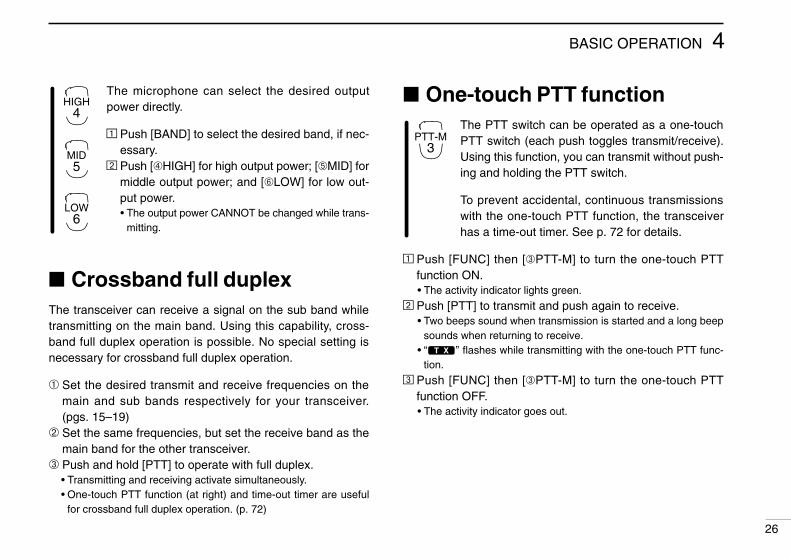
The microphone can select the desired outputpower directly.
Ä Push [BAND] to select the desired band, if nec-essary.
Å Push [➃HIGH] for high output power; [➄MID] formiddle output power; and [➅LOW] for low out-put power.• The output power CANNOT be changed while trans-
mitting.
Crossband full duplexThe transceiver can receive a signal on the sub band whiletransmitting on the main band. Using this capability, cross-band full duplex operation is possible. No special setting isnecessary for crossband full duplex operation.
➀ Set the desired transmit and receive frequencies on themain and sub bands respectively for your transceiver.(pgs. 15–19)
➁ Set the same frequencies, but set the receive band as themain band for the other transceiver.
➂ Push and hold [PTT] to operate with full duplex.• Transmitting and receiving activate simultaneously.• One-touch PTT function (at right) and time-out timer are useful
for crossband full duplex operation. (p. 72)
One-touch PTT functionThe PTT switch can be operated as a one-touchPTT switch (each push toggles transmit/receive).Using this function, you can transmit without push-ing and holding the PTT switch.
To prevent accidental, continuous transmissionswith the one-touch PTT function, the transceiverhas a time-out timer. See p. 72 for details.
Ä Push [FUNC] then [➂PTT-M] to turn the one-touch PTTfunction ON.• The activity indicator lights green.
Å Push [PTT] to transmit and push again to receive.• Two beeps sound when transmission is started and a long beep
sounds when returning to receive.• “$” flashes while transmitting with the one-touch PTT func-
tion.
Ç Push [FUNC] then [➂PTT-M] to turn the one-touch PTTfunction OFF.• The activity indicator goes out.
HIGH4
MID5
LOW6
PTT-M3
IC-2710H.qxd 02.2.8 16:55 Page 26 (1,1)
REPEATER OPERATION5
27
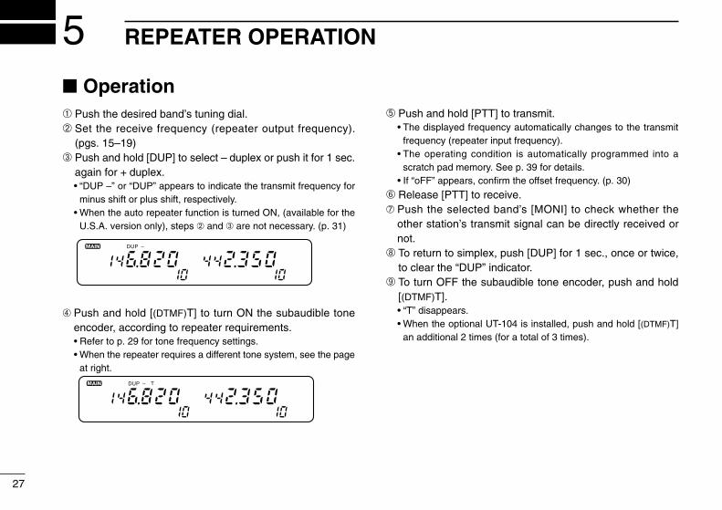
Operation➀ Push the desired band’s tuning dial.➁ Set the receive frequency (repeater output frequency).
(pgs. 15–19)➂ Push and hold [DUP] to select – duplex or push it for 1 sec.
again for + duplex.• “DUP –” or “DUP” appears to indicate the transmit frequency for
minus shift or plus shift, respectively.• When the auto repeater function is turned ON, (available for the
U.S.A. version only), steps ➁ and ➂ are not necessary. (p. 31)
➃ Push and hold [(DTMF)T] to turn ON the subaudible toneencoder, according to repeater requirements.• Refer to p. 29 for tone frequency settings.• When the repeater requires a different tone system, see the page
at right.
➄ Push and hold [PTT] to transmit.• The displayed frequency automatically changes to the transmit
frequency (repeater input frequency).• The operating condition is automatically programmed into a
scratch pad memory. See p. 39 for details.• If “oFF” appears, confirm the offset frequency. (p. 30)
➅ Release [PTT] to receive.➆ Push the selected band’s [MONI] to check whether the
other station’s transmit signal can be directly received ornot.
➇ To return to simplex, push [DUP] for 1 sec., once or twice,to clear the “DUP” indicator.
➈ To turn OFF the subaudible tone encoder, push and hold[(DTMF)T].• “T” disappears.• When the optional UT-104 is installed, push and hold [(DTMF)T]
an additional 2 times (for a total of 3 times).
DUP –
DUP – T
IC-2710H.qxd 02.2.8 16:55 Page 27 (1,1)

5REPEATER OPERATION
28
Ä Push [BAND] to select the desired band, if nec-essary.
Å Set the receive frequency (repeater output fre-quency). (pgs. 15–19)
Ç Push [➆DUP–] to select – duplex; push[➇DUP+] for + duplex.
É Push [FUNC] then [➆TONE] to turn ON the sub-audible tone encoder according to repeater re-quirements.• Refer to p. 29 for tone frequency setting.
• When the repeater requires a different tone system,
see at right.
Ñ Push and hold [PTT] to transmit.Ö Push and hold [➀MONI] to check whether the
other station’s signal can be directly received.Ü Release [PTT] to receive.á To return to simplex operation, push [➈SIMP].à To turn OFF the subaudible tone encoder, push
[FUNC], then [GT-OFF].
D DTMF tonesPush [DTMF-S], then push the keys of the desiredDTMF digits.• The function indicator lights green.• 0–9, A–D, M(E) and #(F) are available.• Cancel the DTMF memory encoder or optional pager/code
squelch function in advance. (pgs. 49, 59, 62)• Push [DTMF-S] again to return the keypad to normal
function control.• The transceiver has 8 DTMF memory channels for au-
topatch operation. See p. 49 for details.
D 1750 Hz toneA 1750 Hz tone is required to access mostEuropean repeaters. The microphone has 1750Hz tone capability.
Ä Push [FUNC].• The mode indicator lights orange.
Å Push [BTONE-1] to transmit a 1750 Hz tone call signal for1 sec.; push and hold [ITONE-2] to transmit a 1750 Hztone call signal for an arbitrary period.• The mode indicator goes out automatically.• The optional HM-90 also has 1750 Hz tone capability.
DTMF S
TONE-1
TONE-2
DUP–7
DUP+8
SIMP9
IC-2710H.qxd 02.2.8 16:55 Page 28 (1,1)
5 REPEATER OPERATION
29
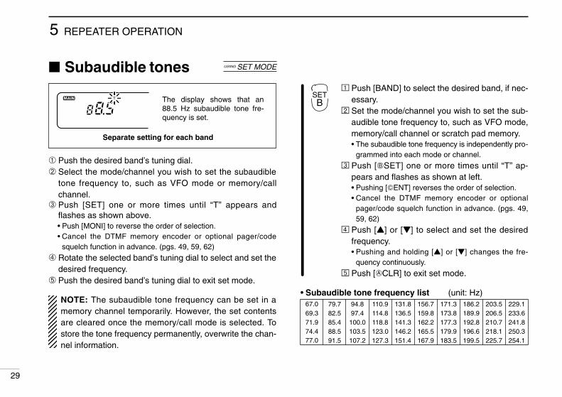
Subaudible tones
➀ Push the desired band’s tuning dial.➁ Select the mode/channel you wish to set the subaudible
tone frequency to, such as VFO mode or memory/callchannel.
➂ Push [SET] one or more times until “T” appears andflashes as shown above.• Push [MONI] to reverse the order of selection.• Cancel the DTMF memory encoder or optional pager/code
squelch function in advance. (pgs. 49, 59, 62)
➃ Rotate the selected band’s tuning dial to select and set thedesired frequency.
➄ Push the desired band’s tuning dial to exit set mode.
NOTE: The subaudible tone frequency can be set in amemory channel temporarily. However, the set contentsare cleared once the memory/call mode is selected. Tostore the tone frequency permanently, overwrite the chan-nel information.
USING SET MODE
1 5 9
T
Separate setting for each band
The display shows that an 88.5 Hz subaudible tone fre-quency is set.
Ä Push [BAND] to select the desired band, if nec-essary.
Å Set the mode/channel you wish to set the sub-audible tone frequency to, such as VFO mode,memory/call channel or scratch pad memory.• The subaudible tone frequency is independently pro-
grammed into each mode or channel.
Ç Push [FSET] one or more times until “T” ap-pears and flashes as shown at left.• Pushing [GENT] reverses the order of selection.• Cancel the DTMF memory encoder or optional
pager/code squelch function in advance. (pgs. 49,59, 62)
É Push [Y] or [Z] to select and set the desiredfrequency.• Pushing and holding [Y] or [Z] changes the fre-
quency continuously.
Ñ Push [ECLR] to exit set mode.
• Subaudible tone frequency list (unit: Hz)
SETB
67.0 79.7 94.8 110.9 131.8 156.7 171.3 186.269.3 82.5 97.4 114.8 136.5 159.8 173.8 189.971.9 85.4 100.0 118.8 141.3 162.2 177.3 192.874.4 88.5 103.5 123.0 146.2 165.5 179.9 196.677.0 91.5 107.2 127.3 151.4 167.9 183.5 199.5
203.5206.5210.7218.1225.7
229.1233.6241.8250.3254.1
IC-2710H.qxd 02.2.8 16:55 Page 29 (1,1)
5REPEATER OPERATION
30
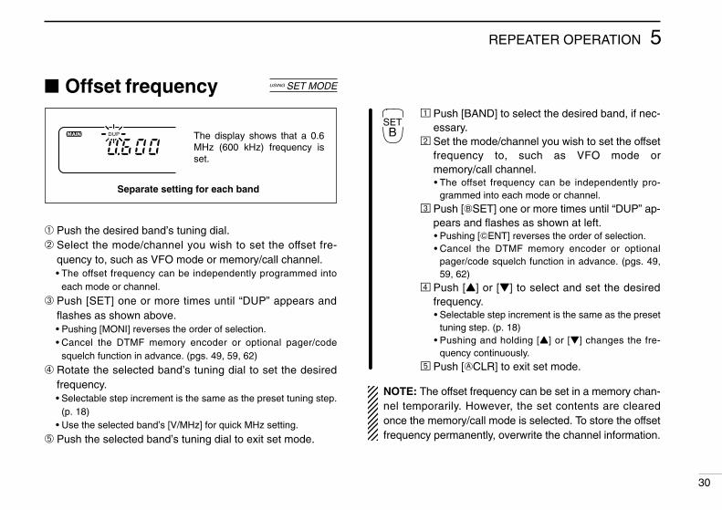
Offset frequency
➀ Push the desired band’s tuning dial.➁ Select the mode/channel you wish to set the offset fre-
quency to, such as VFO mode or memory/call channel.• The offset frequency can be independently programmed into
each mode or channel.
➂ Push [SET] one or more times until “DUP” appears andflashes as shown above.• Pushing [MONI] reverses the order of selection.• Cancel the DTMF memory encoder or optional pager/code
squelch function in advance. (pgs. 49, 59, 62)
➃ Rotate the selected band’s tuning dial to set the desiredfrequency.• Selectable step increment is the same as the preset tuning step.
(p. 18)• Use the selected band’s [V/MHz] for quick MHz setting.
➄ Push the selected band’s tuning dial to exit set mode.
USING SET MODE
Separate setting for each band
The display shows that a 0.6 MHz (600 kHz) frequency is set.
DUP
Ä Push [BAND] to select the desired band, if nec-essary.
Å Set the mode/channel you wish to set the offsetfrequency to, such as VFO mode ormemory/call channel.• The offset frequency can be independently pro-
grammed into each mode or channel.Ç Push [FSET] one or more times until “DUP” ap-
pears and flashes as shown at left.• Pushing [GENT] reverses the order of selection.• Cancel the DTMF memory encoder or optional
pager/code squelch function in advance. (pgs. 49,59, 62)
É Push [Y] or [Z] to select and set the desiredfrequency.• Selectable step increment is the same as the preset
tuning step. (p. 18)• Pushing and holding [Y] or [Z] changes the fre-
quency continuously.Ñ Push [ECLR] to exit set mode.
NOTE: The offset frequency can be set in a memory chan-nel temporarily. However, the set contents are clearedonce the memory/call mode is selected. To store the offsetfrequency permanently, overwrite the channel information.
SETB
IC-2710H.qxd 02.2.8 16:55 Page 30 (1,1)

5 REPEATER OPERATION
31
Auto repeater(U.S.A. version only)
The U.S.A. version automatically activates the repeater set-tings (DUP or DUP– and tone encoder ON/OFF) when theoperating frequency falls within the general repeater outputfrequency range and deactivates them when outside of therange.
D Setting the auto repeater function ON/OFF➀ Push [POWER] to turn power OFF.➁ While pushing [(VOL)SET L] (left side), turn power ON to
enter initial set mode.➂ Push [SET L] one or more times until the “rPt” display ap-
pears as shown below.➃ Rotate the left-hand tuning dial to turn the auto repeater
function ON (“rPt-r1” or “rPt-r2”) or OFF (“rPt-oF”).• “rPt-r1” and “rPt-r2” automatically set the duplex setting and du-
plex/tone encoder settings, respectively.
➄ Push [POWER] momentarily to exit initial set mode.
USING INITIAL SET MODE
Duplex setting:Tone encoder:
Automatic ONAutomatic OFF
Automatic ONAutomatic ON
DUP TDUP
D Frequency range and offset directionFREQUENCY RANGE DUPLEX DIRECTION145.200–145.495 MHz146.610–146.995 MHz
“DUP–” appears
147.000–147.395 MHz “DUP” appears
442.000–444.995 MHz “DUP” appears
447.000–449.995 MHz “DUP–” appears
IC-2710H.qxd 02.2.8 16:55 Page 31 (1,1)

MEMORY OPERATION 6
32
General descriptionThe transceiver has 99 regular memory channels plus 6 scanedge memory channels (3 pairs) on each band; each of thesecan be individually programmed with the following data.
• Operating frequency (pgs. 15–19)• Duplex direction (DUP or DUP–) and its offset frequency
(pgs. 27, 30)• Subaudible tone encoder or tone squelch*1 and its tone fre-
quency (pgs. 27, 29)• Skip information*2 (p. 45)*1An optional UT-104 TONE SQUELCH UNIT is necessary.*2Except for the scan edge memory channels.
Memory channel selectionD Using a tuning dial➀ Push the desired band’s [M/CALL] once or twice to display
“!”.➁ Rotate the same band’s tuning dial to select the desired
memory channel.• Only the programmed memory can be selected.
D Using [Y]/[Z] switchesÄ Push [BAND] to select the desired band, if nec-
essary.Å Push [MR] to select memory mode.Ç Push [Y] or [Z] several times to select the de-
sired memory channel.• Pushing [Y]/[Z] more than 0.5 sec. activates a scan.• If a scan is activated, push [Y] or [Z] again to stop it.
D Using the keypadÄ Push [BAND] to select the desired band, if necessary.Å Push [MR] to select memory mode.Ç Push [GENT] to activate the keypad for numeral input.É Push 2 appropriate digit keys to input a channel
number.• When inputting non-programmed channel numbers
the previous memory channel appears.• To select scan edge channels, “B” and “A” can be
used for A and b respectively.
MR
Y/Z
MR
ENTC
IC-2710H.qxd 02.2.8 16:55 Page 32 (1,1)

6 MEMORY OPERATION
33
Programming a memory channelVFO mode settings, including the set mode contents such assubaudible tone frequency, etc., are programmed into a mem-ory channel.
➀ Set the desired frequency in VFO mode: Push the desired band’s [V/MHz] to select VFO mode. Set the frequency using the desired band’s tuning dial. Set other data (e.g. tone frequency, etc.) if required.
➁ Push [S.MW] momentarily.• “!” and the memory channel number flashes.
➂ Rotate the tuning dial to select the memory channel to be
programmed.• Memory channels not yet programmed are blank.
➃ Push [S.MW] for 1 sec. to program.• 3 beeps may sound.• Memory channel number automatically advances when continu-
ing to push [S.MW] after programming.
CONVENIENTMemory programming can be performed in versatile wayse.g. memory channel to the same (or different) memory chan-nel, memory channel to the call channel, etc.
[EXAMPLE]: Programming 145.870 MHz into memory channel 20 via the remote controller.
1 5 91 5 91 5 9
S.MW MWPush and Rotate for setting
freq., etc.
Rotate
Pushmomentarily
S.MW MWPush
for 1 sec. and continue pushing
V/MHzSCAN
IC-2710H.qxd 02.2.8 16:55 Page 33 (1,1)

6MEMORY OPERATION
34
Programming a memory channel via the microphoneMemory channel programming can be performedvia the microphone.
Ä Push [BAND] to select the desired band, if necessary.Å Set the desired frequency in VFO mode:
Push [VFO] to select VFO mode. Set the frequency using the keypad. Set other data (e.g. offset frequency, duplex direction, subaudi-
ble tone encoder ON/OFF and its frequency), if required.
MWÇ Push [FUNC] then [EMW] momentarily.É Select the memory channel to be programmed:
Push [Y] or [Z] to select the memory channel (direct numeralinput cannot be used).
Ñ Push [FUNC] then [EMW] for 1 sec. to program. 3 beeps may sound and the VFO contents (including the sub-
audible tone frequency, etc.) are programmed. Memory channel number advances when continuing to push
[MW] after programming.
[EXAMPLE]: Programming 145.870 MHz into memory channel 20 via the microphone.
1 5 91 5 91 5 9
Push , Push thenmomentarily
PushPush for 1 sec. and continue pushing
BAND VFO
8DUP+ 7DUP
5MID1MONI 4HIGH
CENT
MW
FUNC ACLR
thenMW
FUNC ACLR
IC-2710H.qxd 02.2.8 16:55 Page 34 (1,1)

6 MEMORY OPERATION
35
Transferring memorycontents
This function transfers a memory channel’s contents into a VFO(or another memory/call channel). This is useful when search-ing for signals around a memory channel frequency and for re-calling the offset frequency, subaudible tone frequency, etc.
➀ Push the desired band’s tuning dial.➁ Select the memory channel to be transferred:
Select memory mode by pushing the selected band’s [M/CALL]once or twice (“!” appears).
Rotate the selected band’s tuning dial to select the memorychannel.
➂ Push [S.MW] momentarily, then rotate the tuning dial to se-lect another memory channel to transfer.• To transfer to the VFO, push and hold [(S.MW)MW] instead of
pushing momentarily.
➃ Push and hold [(S.MW)MW] to transfer when a momentarypush was used in the previous step.
DUP – T DUP – T
S.MW MWPush
+
for 1 sec.
MW
FUNC ACLR
Ä Push [BAND] to select the desired band, if nec-essary.
Å Select the memory channel to be transferred: Push [MR] to select memory mode. Push [Y] or [Z] to select the memory channel; or
push [GENT] then push the desired memory chan-nel number (2 digits) to select the memory channeldirectly.
Ç Push [FUNC] then [EMW] momentarily, thenpush [Y] or [Z] to select another memory chan-nel to transfer.• To transfer to the VFO, push [FUNC] then push and
hold [EMW] instead of pushing momentarily.É Push [FUNC] then [EMW] for 1 sec. to transfer
when a momentary push was used in the pre-vious step.
MW
IC-2710H.qxd 02.2.8 16:55 Page 35 (1,1)
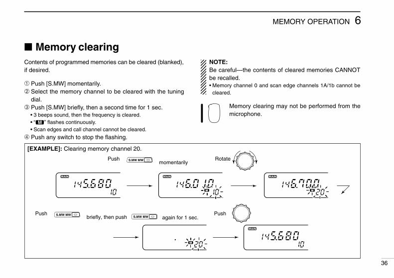
Memory clearingContents of programmed memories can be cleared (blanked),if desired.
➀ Push [S.MW] momentarily.➁ Select the memory channel to be cleared with the tuning
dial.➂ Push [S.MW] briefly, then a second time for 1 sec.
• 3 beeps sound, then the frequency is cleared.• “!” flashes continuously.• Scan edges and call channel cannot be cleared.
➃ Push any switch to stop the flashing.
[EXAMPLE]: Clearing memory channel 20.
NOTE:Be careful—the contents of cleared memories CANNOTbe recalled.• Memory channel 0 and scan edge channels 1A/1b cannot be
cleared.
Memory clearing may not be performed from themicrophone.
6MEMORY OPERATION
36
1 5 9
Push Rotatemomentarily
again for 1 sec.
S.MW MW
Pushbriefly, then push S.MW MW
S.MW MWPush
IC-2710H.qxd 02.2.8 16:55 Page 36 (1,1)

CALL CHANNEL OPERATION7
37
Calling up a call channelEach band has an independent call channel to store a most-often-used frequency for quick recall.
➀ Push the desired band’s [M/CALL] once or twice to displaya large “C” in the memory channel readout.• To transmit on the call channel, select the desired band as the
main band in advance.
➁ Push the same band’s [V/MHz] or [M/CALL] to exit the callchannel.
Ä Push [BAND] to select the desired band, if nec-essary.
Å Push [(MR)CALL] for 1 sec. to select the callchannel.
Transferring call channelcontents
➀ Push the desired band’s tuning dial.➁ Select the call channel by pushing the selected band’s
[M/CALL] once or twice.• A large “C” appears.
➂ Push [S.MW] momentarily, then rotate the tuning dial to se-lect another memory channel to transfer.• To transfer to the VFO, push and hold [(S.MW)MW] instead of
pushing momentarily.➃ Push and hold [(S.MW)MW] to transfer when a momentary
push was used in the previous step.
Ä Push [BAND] to select the desired band, if nec-essary.
Å Push [(MR)CALL] for 1 sec. to select the callchannel.
Ç Push [FUNC], then [EMW] momentarily.• To transfer to the VFO, push [FUNC] then [EMW] in-
stead of pushing [EMW] momentarily.
É Push [FUNC] then [EMW] for 1 sec. to transferwhen momentarily pushing [EMW] in step ➂.
Large “C” shows the call channel is selected.
Small “c” shows VFO mode was selected from the call channel.
CALL
MWA
IC-2710H.qxd 02.2.8 16:55 Page 37 (1,1)

7CALL CHANNEL OPERATION
38
Programming a call channelIn addition to an operating frequency, duplex information andsubaudible tone information (tone encoder or tone squelch*ON/OFF and its frequency) can be programmed into the callchannel.*An optional UT-104 is necessary.
➀ Push the desired band’s tuning dial.➁ Select the call channel by pushing the selected band’s
[M/CALL] once or twice. (A large “C” appears.)➂ Set the desired frequency in VFO mode:
Push [VFO] to select VFO mode. Set the frequency using the keypad. Set other data (e.g. offset frequency, duplex direction, subaudi-
ble tone encoder ON/OFF and its frequency), if required.
➃ Push [(S.MW)MW] for 1 sec. to program.
[EXAMPLE]: Programming 145.120 MHz into the VHF call channel via the microphone.
CONVENIENTThe call channel can also be programmed from the VFO di-rectly (similar to memory programming).
Ä Push [BAND] to select the desired band, if nec-essary.
Å Push [(MR)CALL] for 1 sec. to select the callchannel.
Ç Set the desired frequency in VFO mode:• Push [VFO] to select VFO mode.• Set the desired frequency using the keypad.• Set other data, if required.
É Push [FUNC] then [EMW] for 1 sec. to pro-gram.
MWA
BAND VFO 2SCAN
5MID
1MONI
1MONI
4HIGH
CENT MW
FUNC ACLR
CALL
MRCall channel VFO mode then
for 1 sec.for 1 sec.
BeepBeepBeep
IC-2710H.qxd 02.2.8 16:55 Page 38 (1,1)

SCRATCH PAD MEMORY8
39
What is a scratch padmemory?
During VFO operation, the transceiver automatically memo-rizes operating frequency information, separate from regularmemory channels, when transmitting on a new frequency.The 3 previously operated frequencies for each band can berecalled.
NOTE: When memory mode is selected, the frequency isnot programmed into a scratch pad.
Calling up a scratch padmemory
➀ Select the call channel by pushing the desired band’s[M/CALL] once or twice. (A large “C” appears.)• To transmit on the scratch pad memory, select the desired band
as the main band in advance.
➁ Rotate the selected band’s tuning dial to select a scratchpad memory.• Previously transmitted frequency and one of “L1–L3” appears.• When first applying power or after CPU resetting, scratch pad
memories contain no data and therefore cannot be accessed.
➂ Push the selected band’s [V/MHz] or [M/CALL] to exit thescratch pad memory.
• The 3rd scratch pad memory will be cleared when trans-mitting on a new frequency. If the transmit frequency isalready stored in a scratch pad memory, the scratch padmemory is not cleared but the order is changed.
• When transmitting on a scratch pad memory, the scratchpad memory becomes the 1st scratch pad memory andthe order is changed.
Newest
Oldest
The oldest written frequency is cleared.
Order is changed if transmitting on this channel.
DUP
DUP
IC-2710H.qxd 02.2.8 16:55 Page 39 (1,1)

8SCRATCH PAD MEMORY
40
➀ Push the desired band’s tuning dial.➁ Select the call channel by pushing the selected band’s
[M/CALL] once or twice.• A large “C” appears.
➂ Rotate the selected band’s tuning dial to select the desiredscratch pad memory.• One of “L1”–“L3” appears.
➃ Push [(S.MW)MW] momentarily.• “ ” flashes to indicate VFO as the transferring channel.
➄ Rotate the tuning dial to select the desired memory chan-nel if required.
➅ Push and hold [(S.MW)MW] to transfer.
Ä Push [BAND] to select the desired band, if nec-essary.
Å Push [(MR)CALL] for 1 sec. to select the callchannel.
Ç Push [Z] one or more times to select the de-sired scratch pad memory.
É Push [FUNC] then [EMW] momentarily.• “ ” flashes to indicate VFO as the transferring
channel.
Ñ Push [Y] or [Z] to select the desired memorychannel if required.
Ö Push [FUNC] then [EMW] for 1 sec. to transfer.
Ä Push [BAND] to select the desired band, if nec-essary.
Å Push and hold [(MR)CALL] to select the callchannel.
Ç Push [Z] one or more times to select a duplexscratch pad memory.• Once entering a scratch pad memory, [Y] can also
be used for selection.
É Push [MR] or [VFO] to exit the scratch padmemory.
Transferring scratch padmemory contents
Transferring scratch pad memory contents to the VFO is donesimilarly to transferring regular memory/call channel contents.
CALL
Push for 1 sec.
then
S.MW MW
MWFUNC ACLR
MW
IC-2710H.qxd 02.2.8 16:55 Page 40 (1,1)

SCAN OPERATION9
41
FULL SCAN (p. 42) Repeatedly scans all fre-quencies over the entire band. Used as the sim-plest scan without any pre-liminary settings neces-sary.
PROGRAMMED SCAN(p. 42)
Repeatedly scans bet-ween two user-programmed frequencies. Used for checking for fre-quencies within a speci-fied range such as repeat-er output frequencies, etc. 3 pairs of scan edges are available.
SCAN RESUME CONDITION(p. 46)
5 resume conditions are available: 3 timer scans, pause scan and empty scan. When receiving a signal, pause scan paus-es until the signal disap-pears; timer scans pause for 5, 10 or 15 sec. Empty pause scan pauses until a signal appears.
MEMORY SCAN (p. 42) Repeatedly scans memo-ry channels except for skip channels. Used for often-called channels and by-passing normally busy channels such as repeat-er frequencies.
Band edge
Band edge
Scan
Jump
Band edge
Band edge
Scan
Jump
Scan edges
SKIP
SKIP
Mch 1 Mch 5
Mch 2 Mch 3 Mch 4
Mch 6Mch 80 Mch 7
Pausescan
Receivinga signal
Timerscan
Emptypausescan
Pausing
Pausing
2 sec.
2 sec.
Scan typesScanning searches for transmitted signals automatically andmakes it easier to locate new stations for contact or listeningpurposes.
Scanning with tone squelch:When an optional tone squelch is in use, tone decodescan acivates instead of the above scans. To activate the
above scans with the tone squelch function, push and hold[Y] or [Z] on the microphone.
Each band has 3 scan types and 5 resume conditions to suityour needs. Scans on both bands can be operated separatelyor simultaneously.
IC-2710H.qxd 02.2.8 16:55 Page 41 (1,1)

Scan start/stopD Pre-operation• Common setting: scan resume condition. (p. 46)• For programmed scan: program the scan edges. (p. 43)• For memory scan: program 2 or more memory chan-
nels; set memory skip settings, if de-sired. (p. 45)
D Operation➀ Push the desired band’s tuning dial.➁ Select VFO mode for full/programmed scan; or memory
mode for memory scan with the selected band’s [V/MHz]switch.
➂ Set the selected band’s squelch to the point where noiseis muted.
➃ Push [(V/MHz)SCAN] for 1 sec. to start the scan.• When the optional tone squelch is in use, [(V/MHz)SCAN] starts
the tone scan.• To change the scanning direction, rotate the selected band’s tun-
ing dial.• The memory channel readout indicates the scan type as follows:
9SCAN OPERATION
42
➄ To select the scan range while operating full/programmedscan, push [SET] several times.
➅ To stop the scan, push [(VMHz)SCAN].
Ä Push [BAND] to select the desired band, if nec-essary.
Å Push [VFO] to select VFO mode for full/pro-grammed scan; or push [MR] to select memorymode for memory scan.
Ç Push [HYSQL] or [AZSQL] one or more timesto set the squelch just closed.
É Push [➂SCAN] to start the scan.• [Y]/[Z] also start the scan when pushed and held.
Ñ To select the scan range while operatingfull/programmed scan, push [SET] severaltimes.
Ö To stop the scan push [ECLR].
SCAN2
SETB
During full scan
Push to select full scanand scan edgepairs in sequence.
SET L
During programmed scan
Indicates scan edge channels.• P1 stands for 1A/1b.• P1 to P3 are available when they are programmed.
During memory scan
IC-2710H.qxd 02.2.8 16:55 Page 42 (1,1)

9 SCAN OPERATION
43
Programming scan edgesScan edges can be programmed in the same manner asmemory channels. Scan edges are programmed into pairs ofscan edge channels, 1A/1b to 3A/3b, in memory channels.
➀ Push the desired band’s tuning dial.➁ Set the desired frequency in VFO mode:
Push the selected band’s [V/MHz] to select VFO mode. Set the frequency using the selected band’s tuning dial. Set other data (e.g. offset frequency, etc.) if required.
➂ Push [S.MW] momentarily.• “!” and the memory channel number flashes.
[EXAMPLE]: Programming 145.30 MHz and 145.80 MHz for the VHF scan edges 1A and 1b.
1 5 91 5 9
S.MW MWPushVHFtuningdial.
then rotateRotate
Push
momentarilyS.MW MW
S.MW MW
Push
and hold
continue pushing
Program 1b in the same manner.
➃ Rotate the tuning dial to select a scan edge channel (1A to3A).
➄ Push [(S.MW)MW] for 1 sec. to program.• 3 beeps may sound and the frequency is programmed.• Scan edge 1b is automatically selected when continuing to push
[(S.MW)MW] after programming.➅ To program a frequency for the other pair of scan edges,
1b to 3b, repeat steps ➃ and ➄.• If the same frequency is programmed into both scan edges, pro-
grammed scan will not function.
IC-2710H.qxd 02.2.8 16:55 Page 43 (1,1)

9SCAN OPERATION
44
Programming scan edges viathe microphone
Ä Push [BAND] to select the desired band, if nec-essary.
Å Set the desired frequency in VFO mode: Push [VFO] to select VFO mode. Set the frequency using the keypad.
Ç Push [FUNC] then [EMW] momentarily.É Push [Y] or [Z] to select scan edge channels.Ñ Push [FUNC] then [EMW] for 1 sec. to pro-
gram.
[EXAMPLE]: Programming 145.30 MHz and 145.80 MHz for the VHF scan edges 1A and 1b.
1 5 91 5 91 5 9
Push Push thenmomentarily
Program 1bin the samemanner.
PushPush for 1 sec. and continue pushing
VFO
3PRIO 0VOL
5MID1MONI 4HIGH
C
A
ENT
MW
FUNC ACLR
thenMW
FUNC CLR
Y
3 beeps may sound and the VFO contents (including the sub-audible tone frequency, etc.) are programmed.
Memory channel number advances to the next scan edge chan-nel (1b to 3b) when continuing to push [EMW] after program-ming.
Ö To program a frequency for the other scan edge channel,repeat steps Å and Ñ.
MWA
IC-2710H.qxd 02.2.8 16:55 Page 44 (1,1)

9 SCAN OPERATION
45
Skip channel settingThe memory skip function speeds up scanning by checkingonly desired memory channels. Set the memory channels tobe skipped or scanned as follows.
➀ Push the desired band’s tuning dial.➁ Select the memory channel to program or to cancel the
skip function on: Select memory mode by pushing the selected band’s [M/CALL]
once or twice. Rotate the selected band’s tuning dial to select the memory
channel.
➂ Push [SET] one or more times until “CHS” appears asshown above.• Pushing [MONI] reverses the order of selection.
➃ Rotate the selected band’s tuning dial to turn the skip func-tion ON or OFF on the selected channel.• “~” appears : The memory channel is skipped during(CHS-on) memory scan.
• “~” disappears : The memory channel is scanned during(CHS-OFF) memory scan.
USING SET MODE
Separate setting for each band
SKIP
The display shows that VHF memory channel 10 is set as a skip channel.
➄ Push the selected band’s tuning dial to exit set mode.
NOTE: Scan edge memory channels cannot be specifiedas skip channels, however, they are skipped during mem-ory scan anyway.
Ä Push [BAND] to select the desired band, if nec-essary.
Å Select the memory channel to program or tocancel the skip function on: Select memory mode by pushing [MR]. Push [Y] or [Z] to select a memory channel.
Ç Push [FSET] one or more times until “CHS” ap-pears as shown at left.• Pushing [GENT] reverses the order of selection
once entering set mode.
É Push [Y] or [Z] to set or cancel the skip infor-mation.• See item ➃ at left for skip indicator details.
Ñ Push [ECLR] to exit set mode.
SETB
IC-2710H.qxd 02.2.8 16:55 Page 45 (1,1)

9SCAN OPERATION
46
Scan resumecondition
The scan resume condition can be selected as timer, pauseor empty pause scan. The empty pause scan is useful forfinding unused frequencies. The resume condition is alsoused for priority watch. (p. 47)
➀ Push the desired band’s tuning dial.➁ Push [SET] one or more times until “SCt” or “SCP” appears
as shown above.• Pushing [MONI] reverses the order of selection.• Cancel the DTMF encoder or optional pager/code squelch in ad-
vance. (p. 49, 59, 62)
Separate setting for each band
The display shows that the scan resumes 15 sec. after it stops.
USING SET MODE ➂ Rotate the selected band’s tuning dial to set the desiredtimer.• “SCt-15” : Scan pauses 15 sec. while receiving a signal.• “SCt-10” : Scan pauses 10 sec. while receiving a signal.• “SCt-5” : Scan pauses 5 sec. while receiving a signal.• “SCP-2” : Scan pauses until the signal disappears and then re-
sumes 2 sec. thereafter.• “SCt-EP” : Scan pauses on a frequency that is not busy and re-
sumes 2 sec. after a signal appears.
➃ Push the selected band’s tuning dial to exit set mode.
Ä Push [BAND] to select the desired band, if nec-essary.
Å Push [FSET] one or more times until “SCt” or“SCP” appears as shown at left.• Pushing [GENT] reverses the order of selection
once entering set mode.• Cancel the DTMF memory encoder or pager/code
squelch in advance. (pgs. 49, 59, 62)
Ç Push [Y] or [Z] to select the scan resume con-dition.• See item ➂ above for scan resume condition details.
É Push [ECLR] to exit set mode.
SETB
IC-2710H.qxd 02.2.8 16:55 Page 46 (1,1)
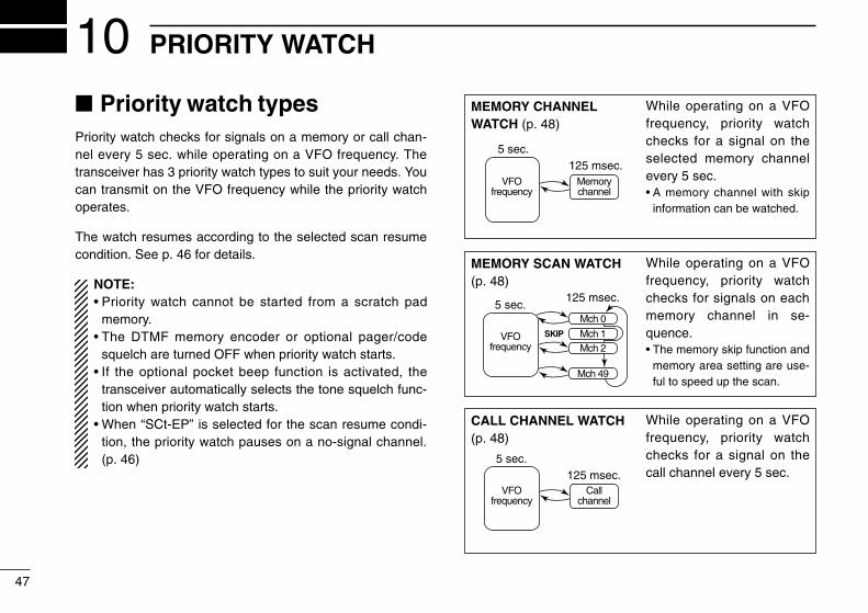
PRIORITY WATCH10
47
Priority watch typesPriority watch checks for signals on a memory or call chan-nel every 5 sec. while operating on a VFO frequency. Thetransceiver has 3 priority watch types to suit your needs. Youcan transmit on the VFO frequency while the priority watchoperates.
The watch resumes according to the selected scan resumecondition. See p. 46 for details.
NOTE:• Priority watch cannot be started from a scratch pad
memory.• The DTMF memory encoder or optional pager/code
squelch are turned OFF when priority watch starts.• If the optional pocket beep function is activated, the
transceiver automatically selects the tone squelch func-tion when priority watch starts.
• When “SCt-EP” is selected for the scan resume condi-tion, the priority watch pauses on a no-signal channel.(p. 46)
MEMORY CHANNELWATCH (p. 48)
MEMORY SCAN WATCH(p. 48)
CALL CHANNEL WATCH(p. 48)
VFOfrequency
Memorychannel
5 sec.125 msec.
VFOfrequency
Mch 1
Mch 0
Mch 2
Mch 49
5 sec.125 msec.
SKIP
VFOfrequency
Callchannel
5 sec.125 msec.
While operating on a VFOfrequency, priority watchchecks for a signal on theselected memory channelevery 5 sec.• A memory channel with skip
information can be watched.
While operating on a VFOfrequency, priority watchchecks for signals on eachmemory channel in se-quence.• The memory skip function and
memory area setting are use-ful to speed up the scan.
While operating on a VFOfrequency, priority watchchecks for a signal on thecall channel every 5 sec.
IC-2710H.qxd 02.2.8 16:55 Page 47 (1,1)

10PRIORITY WATCH
48
Priority watch operation➀ Push the desired band’s tuning dial.➁ Select VFO mode; then, set an operating frequency.➂ Set the watching channel(s).
For memory channel watch:Select the desired memory channel.For memory scan watch:Select memory mode; then, push [(V/MHz)SCAN] for 1 sec.to start memory scan.For call channel watch:Select the call channel by pushing the selected band’s[M/CALL] once or twice.
➃ Push the selected band’s [(M/CALL)PRIO] for 1 sec. to startthe watch.• The transceiver checks the memory or call channel frequency
every 5 sec.• The watch resumes according to the selected scan resume con-
dition. (p. 46)• While the watch is pausing, pushing the selected band’s
[M/CALL] resumes the watch manually.
➄ Push the selected band’s [M/CALL] while the displayshows the VFO frequency to stop the watch.
PR I O
While pausing on the memory or call chan-nel, “PRIO” flashes.
Ä Push [BAND] to select the desired band, if nec-essary.
Å Select VFO mode; then, set an operating fre-quency.
Ç Set the watching channel(s).For memory channel watch:Push [MR] then [Y] or [Z] to select the desiredmemory channel.For memory scan watch:Push [MR] then [➁SCAN] to start the memoryscan.For call channel watch:Push and hold [(MR)CALL] to select the callchannel.
É Push [➂PRIO] to start the watch.• The transceiver checks the memory or call channel
frequency every 5 sec.• The watch resumes according to the selected scan
resume condition. (p. 46)• To resume the watch manually while pausing, push
[➂PRIO] or [ECLR].
Ñ To stop the watch, push [ECLR] once (or twicewhile watch pauses).
PRIO3
IC-2710H.qxd 02.2.8 16:55 Page 48 (1,1)
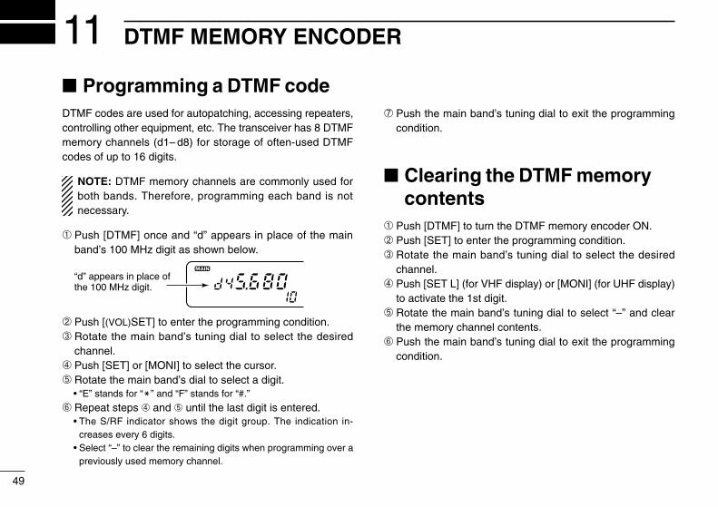
DTMF MEMORY ENCODER11
49
Programming a DTMF codeDTMF codes are used for autopatching, accessing repeaters,controlling other equipment, etc. The transceiver has 8 DTMFmemory channels (d1– d8) for storage of often-used DTMFcodes of up to 16 digits.
NOTE: DTMF memory channels are commonly used forboth bands. Therefore, programming each band is notnecessary.
➀ Push [DTMF] once and “d” appears in place of the mainband’s 100 MHz digit as shown below.
➁ Push [(VOL)SET] to enter the programming condition.➂ Rotate the main band’s tuning dial to select the desired
channel.➃ Push [SET] or [MONI] to select the cursor.➄ Rotate the main band’s dial to select a digit.
• “E” stands for “M” and “F” stands for “#.”
➅ Repeat steps ➃ and ➄ until the last digit is entered.• The S/RF indicator shows the digit group. The indication in-
creases every 6 digits.• Select “–” to clear the remaining digits when programming over a
previously used memory channel.
➆ Push the main band’s tuning dial to exit the programmingcondition.
Clearing the DTMF memorycontents
➀ Push [DTMF] to turn the DTMF memory encoder ON.➁ Push [SET] to enter the programming condition.➂ Rotate the main band’s tuning dial to select the desired
channel.➃ Push [SET L] (for VHF display) or [MONI] (for UHF display)
to activate the 1st digit.➄ Rotate the main band’s tuning dial to select “–” and clear
the memory channel contents.➅ Push the main band’s tuning dial to exit the programming
condition.
“d” appears in place of the 100 MHz digit.
IC-2710H.qxd 02.2.8 16:55 Page 49 (1,1)

11DTMF MEMORY ENCODER
50
Programming a DTMF code via the microphone
[EXAMPLE]: Programming “5428AB453” into DTMF memory channel “d4.”
DTMF codes can be directly programmed via thekeypad on the microphone. The contents can beoverwritten, but cannot be cleared via the micro-phone. See the page at left for clearing the con-tents.
Ä Push [FUNC] then [➅DTMF] to turn the DTMF memoryfunction ON.• “d” appears in place of the 100 MHz digit.
Å Push [FSET] to enter the programming condition.Ç Push [Y] or [Z] to select the desired channel.
DTMF6
É Push the desired digit keys.• When the first digit is input, previous memory contents are
cleared automatically.• “E” stands for “M” and “F” stands for “#.”• Push [Y] then [Z], and repeat this step when making a mistake.• The S/RF indicator shows the digit group. The indication in-
creases every 6 digits.
Ñ Push the [BAND] to exit the programming condition.• The [ECLR] key cannot be used to exit. If pushed, “A” is input,
and the previously programmed data is erased. Reprogram againin such a case.
Push
8DUP+5MID 5MID4HIGH 4HIGHACLR
thenFUNC
DTMF
6LOW BSET
BSET2SCAN 3PRIO BAND
IC-2710H.qxd 02.2.8 16:55 Page 50 (1,1)

11 DTMF MEMORY ENCODER
51
Transmitting a DTMF codeD Using the DTMF memory function
(automatic transmission)The selected DTMF code is transmitted at each push of thePTT switch when the DTMF memory encoder is turned ON.
➀ Push [DTMF] to turn the DTMF memory encoder ON.• “d” appears in place of the main band’s 100 MHz digit.
➁ Push [SET] to enter the programming condition.➂ Rotate the main band’s tuning dial to select the desired
DTMF memory channel.➃ Push [PTT] to transmit the selected DTMF code.
• At each push of [PTT], the selected DTMF code is transmitted.• The speaker emits the DTMF tones sent.
➄ Push [DTMF] to cancel the function.• “d” disappears.• When an optional UT-49 is installed, push [DTMF] several times until
a number appears for the 100 MHz digit and “REMO” disappears.
Ä Push [FUNC] then [➅DTMF] to turn the DTMFmemory encoder ON.• “d” appears in place of the main band’s 100 MHz
digit.
Å Push [FSET] to enter the programming condi-tion.
Ç Push [Y] or [Z] to select the desired channel.
DTMF6
É Push [PTT] to transmit the selected DTMF code.• At each push of [PTT], the selected DTMF code is transmitted.
Ñ Push [ECLR] to cancel the function.
D Transmitting a DTMF memory channel directlyÄ Push [FUNC] then [➅DTMF] to turn the DTMF
memory encoder ON.• “d” appears in place of the main band’s 100 MHz
digit.
Å Push [DTMF-S], then push the desired DTMFchannel number.• “1” to “8” are available for channel numbers.
Ç Push [DTMF-S] again to deactivate the DTMFsetting.
É Push [ECLR] to turn the DTMF memory en-coder OFF.• When the DTMF memory encoder is turned ON con-
tinuously, each push of the PTT transmits the previ-ously selected DTMF code.
DTMF-S
IC-2710H.qxd 02.2.8 16:55 Page 51 (1,1)

11DTMF MEMORY ENCODER
52
DTMF speedThe rate at which DTMF memories send individual DTMFcharacters can be set to accommodate operating needs. Thissetting does not affect an optional pager or code squelch op-eration.
➀ Push [POWER] to turn power OFF.➁ While pushing [(VOL)SET L] (left side), push [POWER] for
1 sec. to turn power ON and enter initial set mode.➂ Push [(VOL)SET L] or [(SQL)MONI] to select the “dtd” dis-
play as shown above.➃ Rotate the main band’s tuning dial to select the desired
speed as shown in the table at right.➄ Push [POWER] momentarily to exit initial set mode.
USING INITIAL SET MODE
Common setting for each band
The display shows the fas-test DTMF speed is selected.
DISPLAY INTERVAL SPEEDdtd-1 100 msec. 5.0 cpsdtd-2 200 msec. 2.5 cpsdtd-3 300 msec. 1.6 cpsdtd-5 500 msec. 1.0 cps
cps=characters/second
IC-2710H.qxd 02.2.8 16:55 Page 52 (1,1)

POCKET BEEP AND TONE SQUELCH12
53
Ä Push [BAND] to select the desired band, if nec-essary.
Å Set the operating frequency.Ç Program the subaudible tone frequency in set
mode.• See p. 29 for programming details.
É Push [FUNC] then [➇T SQLS] to turn thepocket beep ON.• Turn OFF the pager or code squelch to activate the
pocket beep. (pgs. 59, 62) The pocket beep cannotbe used with the pager or code squelch.
Ñ When a signal with the correct tone is received,the transceiver emits beep tones for 30 sec.and flashes “S.”
Ö Push [PTT] to answer or push [ECLR] to stopthe beeps and flashing.• Tone squelch is automatically selected.• Pushing [FUNC] then [➈TSQL] also selects the tone
squelch.
Ü To cancel the function, push [FUNC] then[GT-OFF].
D Waiting for a call from a specific stationA subaudible tone matched with the stations frequency isnecessary. Use the tone squelch on the next page or a sub-audible tone encoder (p. 29).
Pocket beep operationThis function uses subaudible tones for calling and can beused as a “common pager” to inform you that someone hascalled while you were away from the transceiver.
To operate the pocket beep function, an optional UT-104 isnecessary. See p. 65 for installation details.
D Waiting for a call from a specific station➀ Push the desired band’s tuning dial.➁ Set the operating frequency.➂ Program the subaudible tone frequency in set mode.
• See p. 29 for programming details.
➃ Push [(DTMF)T] for 1 sec., 2 times to indicate “T SQLS”in the function display.• Turn OFF the pager or code squelch to activate the pocket beep.
(pgs. 59, 62) The pocket beep cannot be used in combinationwith the pager or code squelch.
➄ When a signal with the correct tone is received, the trans-ceiver emits beep tones and flashes “S”.• Beep tones sound for 30 sec. To stop the beeps manually, push
the tuning dial (or any key).• “S” flashes coninuously until step ➅ or ➆.• When receiving another call while “S” is flashing, no beeps sound.
➅ Push [PTT] to answer.• Tone squelch is automatically selected when transmitting.
➆ Push [(DTMF)T] for 1 sec. once or twice to cancel the function.
T SQLS8
T-OFFC
optional UT-104
IC-2710H.qxd 02.2.8 16:55 Page 53 (1,1)

12POCKET BEEP AND TONE SQUELCH
54
Tone squelch operationThe tone squelch opens only when receiving a signal with thesame pre-programmed subaudible tone. This function can beactivated on both bands with separate tone frequencies si-multaneously. To operate the tone squelch function, an op-tional UT-104 is necessary.
➀ Push the desired band’s tuning dial.➁ Set the operating frequency.➂ Program the subaudible tone frequency in set mode.
• See p. 29 for programming details.
➃ Push [(DTMF)T] for 1 sec., several times until “T SQL” ap-pears in the function display.• The pager or code squelch can be used together with the tone
squelch. (p. 62)
➄ When the received signal includes the correct tone, thesquelch opens and the signal can be heard.• When the received signal includes an incorrect tone, the squelch
does not open. However, the S/RF indicator shows the receivedsignal strength.
• To open the accessed band’s squelch manually, push the ac-cessed band’s [MONI].
➅ Operate the transceiver in the normal way (push [PTT] totransmit; release [PTT] to receive).
➆ To cancel the tone squelch, push [(DTMF)T] for 1 sec.• “T SQL” disappears from the function display.
Ä Push [BAND] to select the desired band, if nec-essary.
Å Set the operating frequency.Ç Program the subaudible tone frequency in set
mode.• See p. 29 for programming details.
É Push [FUNC] then [➈T SQL] to turn the tonesquelch ON.• The pager or code squelch can be used with the
tone squelch. (p. 62)
Ñ When the received signal includes the correcttone, the squelch opens and the signal can beheard.• When the received signal includes and incorrect
tone, the squelch does not open. However, the S/RFindicator shows the received signal strength.
• To open the accessed band’s squelch manually,push [➀MONI].
Ö Operate the transceiver in the normal way(push [PTT] to transmit; release [PTT] to re-ceive).
Ü To cancel the tone squelch, push [FUNC] then[GT-OFF].
T SQL9
T-OFFC
IC-2710H.qxd 02.2.8 16:55 Page 54 (1,1)
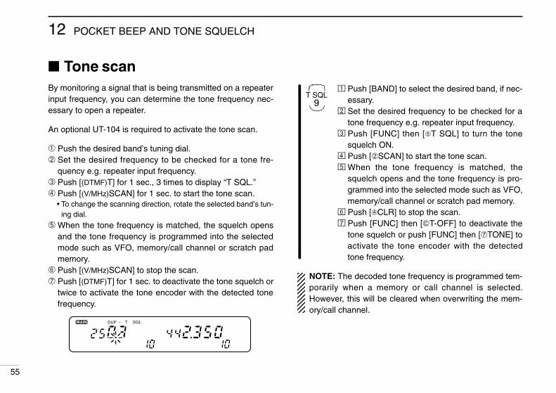
12 POCKET BEEP AND TONE SQUELCH
55
Ä Push [BAND] to select the desired band, if nec-essary.
Å Set the desired frequency to be checked for atone frequency e.g. repeater input frequency.
Ç Push [FUNC] then [➈T SQL] to turn the tonesquelch ON.
É Push [➁SCAN] to start the tone scan.Ñ When the tone frequency is matched, the
squelch opens and the tone frequency is pro-grammed into the selected mode such as VFO,memory/call channel or scratch pad memory.
Ö Push [ECLR] to stop the scan.Ü Push [FUNC] then [GT-OFF] to deactivate the
tone squelch or push [FUNC] then [➆TONE] toactivate the tone encoder with the detectedtone frequency.
NOTE: The decoded tone frequency is programmed tem-porarily when a memory or call channel is selected.However, this will be cleared when overwriting the mem-ory/call channel.
Tone scanBy monitoring a signal that is being transmitted on a repeaterinput frequency, you can determine the tone frequency nec-essary to open a repeater.
An optional UT-104 is required to activate the tone scan.
➀ Push the desired band’s tuning dial.➁ Set the desired frequency to be checked for a tone fre-
quency e.g. repeater input frequency.➂ Push [(DTMF)T] for 1 sec., 3 times to display “T SQL.”➃ Push [(V/MHz)SCAN] for 1 sec. to start the tone scan.
• To change the scanning direction, rotate the selected band’s tun-ing dial.
➄ When the tone frequency is matched, the squelch opensand the tone frequency is programmed into the selectedmode such as VFO, memory/call channel or scratch padmemory.
➅ Push [(V/MHz)SCAN] to stop the scan.➆ Push [(DTMF)T] for 1 sec. to deactivate the tone squelch or
twice to activate the tone encoder with the detected tonefrequency.
DUP – T SQL
T SQL9
IC-2710H.qxd 02.2.8 16:55 Page 55 (1,1)
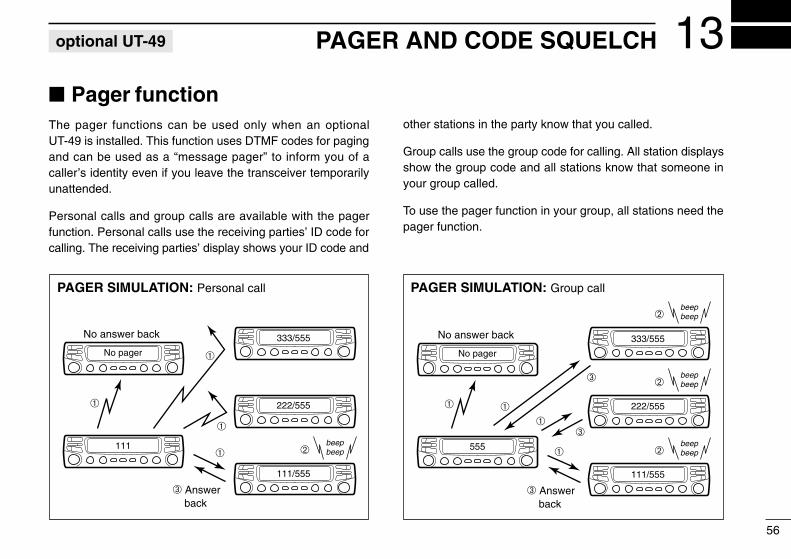
PAGER AND CODE SQUELCH 13
56
Pager functionThe pager functions can be used only when an optionalUT-49 is installed. This function uses DTMF codes for pagingand can be used as a “message pager” to inform you of acaller’s identity even if you leave the transceiver temporarilyunattended.
Personal calls and group calls are available with the pagerfunction. Personal calls use the receiving parties’ ID code forcalling. The receiving parties’ display shows your ID code and
other stations in the party know that you called.
Group calls use the group code for calling. All station displaysshow the group code and all stations know that someone inyour group called.
To use the pager function in your group, all stations need thepager function.
No answer back
➂ Answer back
No pager
111
333/555
222/555
111/555
➀
➀
➀
➀
➁beepbeep
No answer back
➂ Answer back
No pager
555
333/555
222/555
111/555
➀
➀➀➀
➁beepbeep
➁beepbeep
➁beepbeep
➂
➂
PAGER SIMULATION: Personal call PAGER SIMULATION: Group call
optional UT-49
IC-2710H.qxd 02.2.8 16:55 Page 56 (1,1)

13 PAGER AND CODE SQUELCH
57
Code channelsD Before programmingThe pager and code squelch functions require ID codes and agroup code. These codes are 3-digit DTMF codes and mustbe written in the code channels before operation. The trans-ceiver has separate code channels for each band.
D Code channel assignment
* Code channel P automatically memorizes an ID code when receiv-ing a pager call. The contents in channel P cannot be changedmanually.
ID ORGROUP CODE
CODE CHANNELNUMBER
“RECEIVE ACCEPT”OR “RECEIVE INHIBIT”
Your ID code 0 “Receive accept” only.
Other parties’ID code 1–5
“Receive inhibit” shouldbe programmed in each
channel.
Group code One of 1–5“Receive accept” must be
programmed.
Memory space* P “Receive inhibit” only.
RECEIVE ACCEPT AND INHIBITCode channels 1–5 can store the transmit codes for per-sonal calls to other individuals and the group codes forgroup calls.
The group codes should be programmed as “receive ac-cept” (“ ” disappears) to receive all calls from groupmembers.
If transmit codes are not programmed as “receive inhibit,”the transceiver accepts calls directed to other individualsand your answer back may confuse other members in yourgroup—this is not a selective calling system. Therefore,transmit codes should be programmed as “receive inhibit”(“ ” appears) so the transceiver rejects calls directed toother individuals.
SKIP
SKIP
IC-2710H.qxd 02.2.8 16:55 Page 57 (1,1)

13PAGER AND CODE SQUELCH
58
Code programming➀ Push the desired band’s tuning dial.
• Each band has separate code channels.
➁ Push [DTMF] 2 times to turn the pager function ON.• “P” appears in place of the 100 MHz digit.
➂ Push [(VOL)SET] to select the code channel setting display.➃ Rotate the selected band’s tuning dial to select the desired
code channel, 0–5.• Code channel P cannot be used for programming.
➄ Push [(SQL)MONI] or [(VOL)SET] to select the digit to beprogrammed.
➅ Rotate the selected band’s tuning dial to set the digit.➆ Repeat ➄ and ➅ until the last digit is programmed.➇ Push [DTMF] to set the code channel for “receive inhibit”
or “receive accept.”• When “receive inhibit” is set, “ ” appears.• Code channel 0 cannot be set as “receive inhibit.”• See p. 57 for “receive inhibit” or “receive accept” details.
➈ Push the selected band’s tuning dial to exit the setting dis-play.
SKIP
1 5 9
The display shows that VHF code channel 0 (your ID code) is pro-grammed for 248.
Ä Push [BAND] to select the desired band, if nec-essary.• Each band has separate code channels.
Å Push [FUNC] then [➃PGR] to turn the pagerfunction ON.• “P” appears in place of the 100 MHz digit.
Ç Push [FSET] to select the code channel settingdisplay.
É Push [Y] or [Z] to select and set the desiredcode channel, 0–5.• Code channel P cannot be used for programming.
Ñ Push the numeral keys to enter the desired3-digit code.• Digits are automatically stored once the 3rd digit has
been entered.
Ö Push [FSET] to set the code channel for “re-ceive inhibit” or “receive accept.”• When “receive inhibit” is set, “ ” appears.• Code channel 0 cannot be set as “receive inhibit.”• See p. 57 for “receive inhibit” or “receive accept” de-
tails.
Ü Push [ECLR] to exit the setting display.
SKIP
SETB
IC-2710H.qxd 02.2.8 16:55 Page 58 (1,1)

13 PAGER AND CODE SQUELCH
59
Pager operationD Calling a specific station➀ Push the desired band’s tuning dial.➁ Set the operating frequency.➂ Push [DTMF] 2 times to turn the pager function ON.
• “P” appears in place of the 100 MHz digit.• An optional tone squelch can be used together with the pager
function, although the pocket beep cannot be used. (p. 54)
➃ Select the desired code channel: Push [SET]. Rotate the selected band’s tuning dial to select the code chan-
nel. Push the selected band’s tuning dial to exit the setting display.
➄ Push [PTT] to transmit the pager code.➅ Wait for an answer back.
• When the transceiver receives an answer back code, the func-tion display shows the other parties’ ID or group code and beeps.(p. 60)
➆ After confirming a connection, push the selected band’stuning dial to display the operating frequency.• DO NOT push numeral keys on the microphone while a 3-digit
code is indicated, or code channel contents are changed.
➇ Push [DTMF] once to select code squelch or 2 times (or 3times for U.S.A. version) to select the non-selective callingsystem.
Ä Push [BAND] to select the desired band, if nec-essary.
Å Set the operating frequency.Ç Push [FUNC] then push [➃PGR] to turn the
pager function ON.• “P” appears in place of the 100 MHz digit.• An optional tone squelch can be used together with
the pager function. (p. 54)
É Select the desired code channel: Push [FSET]. Push [Y] or [Z] to select the code channel. Push [ECLR] to exit the setting display.
Ñ Push [PTT] to transmit the pager code.Ö Wait for an answer back.
• When the transceiver receives an answer backcode, the function display shows the other parties’ID or group code and beeps. (p. 60)
Ü After confirming a connection, push [ECLR] todisplay the operating frequency.• DO NOT push numeral keys on the microphone
while a 3-digit code is indicated, or code channelcontents are changed.
á Push [FUNC] then [➄C SQL] to select codesquelch or push [ECLR] to select the non-se-lective calling system.• Pushing [FUNC] then [FD-OFF] also selects the
non-selective calling system.
PGR4
IC-2710H.qxd 02.2.8 16:55 Page 59 (1,1)

13PAGER AND CODE SQUELCH
60
D Waiting for a call from a specific station➀ Push the desired band’s tuning dial.➁ Set the operating frequency.➂ Push [DTMF] to turn the pager function ON.
• “P” appears in place of the 100 MHz digit.• An optional tone squelch can be used together with the pager
function, although the pocket beep cannot be used. (p. 54)
➃ Wait for a call.• When receiving a call, the other parties’ ID or group code ap-
pears; “S” and the channel number blink as shown on the nextpage.
• DO NOT push numeral keys on the microphone while a 3-digitcode is indicated, or code channel contents are changed.
➄ Push [PTT] to send an answer back call and display theoperating frequency.
➅ Push [DTMF] once to select the code squelch system or 2times (or 3 times for U.S.A. version) to select the non-se-lective calling system.
Ä Push [BAND] to select the desired band, if nec-essary.
Å Set the operating frequency.Ç Push [FUNC] then [➃PGR] to turn the pager
function ON.• “P” appears in place of the 100 MHz digit.• An optional tone squelch can be used together with
the pager function. (p. 54)
É Wait for a call.• When receiving a call, the other parties’ ID or group
code appears; “S” and the channel number blinkas shown on the next page.
• DO NOT push numeral keys on the microphonewhile a 3-digit code is indicated, or code channelcontents are changed.
Ñ Push [PTT] to send an answer back call anddisplay the operating frequency.
Ö Push [FUNC] then [➄C SQL] to select codesquelch or push [ECLR] to select the non-se-lective calling system.• Pushing [FUNC] then [FD-OFF] also selects the
non-selective calling system.
PGR4
IC-2710H.qxd 02.2.8 16:55 Page 60 (1,1)

13 PAGER AND CODE SQUELCH
61
Code squelch functionThe code squelch function can be used only when an optionalUT-49 is installed.
Code squelch operation provides communication with silentstandby since you only receive calls from stations which knowyour ID or group code. To use the code squelch function inyour group, all stations need the code squelch function.
The code squelch function transmits a 3-digit code prior tovoice transmission in order to open the receiving station’scode squelch.
PERSONAL CALLSThis display appears whenyou are called with your IDcode and the calling station’sID code is 263.
GROUP CALLSThis display appears whenyou are called with the groupcode, 123, and 123 has beenprogrammed into code chan-nel 5.
ERROR INFORMATIONWhen the transceiver receivesan incomplete signal, “E” ap-pears.
SKIP1 5 9
1 5 9
SKIP1 5 9
“E” appears
CODE SQUELCH SIMULATION:
No code squelchfunction
111
111/555
000/555
000
IC-2710H.qxd 02.2.8 16:55 Page 61 (1,1)

13PAGER AND CODE SQUELCH
62
Ä Push [BAND] to select the desired band, if nec-essary.
Å Set the operating frequency.Ç Push [FUNC] then [➄C SQL] to turn the code
squelch ON.• “C” appears in place of the 100 MHz digit.• An optional tone squelch can be used together with
the code squelch. (p. 54)
É Select the desired code channel: Push [FSET]. Push [Y] or [Z] to select the code channel. Push [ECLR] to exit the setting display.
Ñ Operate the transceiver in the normal way(push [PTT] to transmit; release [PTT] to re-ceive).• Prior to voice transmission, a 3-digit transmit code
is sent each time [PTT] is pushed in order to openthe receiving station’s code squelch.
Ö To cancel the code squelch push [ECLR].• Pushing [FUNC] then [FD-OFF] also cancels the
code squelch.
Code squelch operation➀ Push the desired band’s tuning dial.➁ Set the operating frequency.➂ Push [DTMF] 3 times to turn the code squelch ON.
• “C” appears in place of the 100 MHz digit as shown below.• An optional tone squelch can be used together with the code
squelch, although the pocket beep cannot be used. (p. 54)
➃ Select the desired code channel: Push [SET]. Rotate the selected band’s tuning dial to select the code chan-
nel. Push the selected band’s tuning dial to exit the setting display.
➄ Operate the transceiver in the normal way (push [PTT] totransmit; release [PTT] to receive).• Prior to voice transmission, a 3-digit transmit code is sent each
time [PTT] is pushed in order to open the receiving station’s codesquelch.
➅ To cancel the code squelch, push [DTMF] once (or 2 timesfor the U.S.A. version).• The display shows the operating frequency.
“C” appears in placeof the 100 MHz digit.
C SQL5
CLRA
IC-2710H.qxd 02.2.8 16:55 Page 62 (1,1)
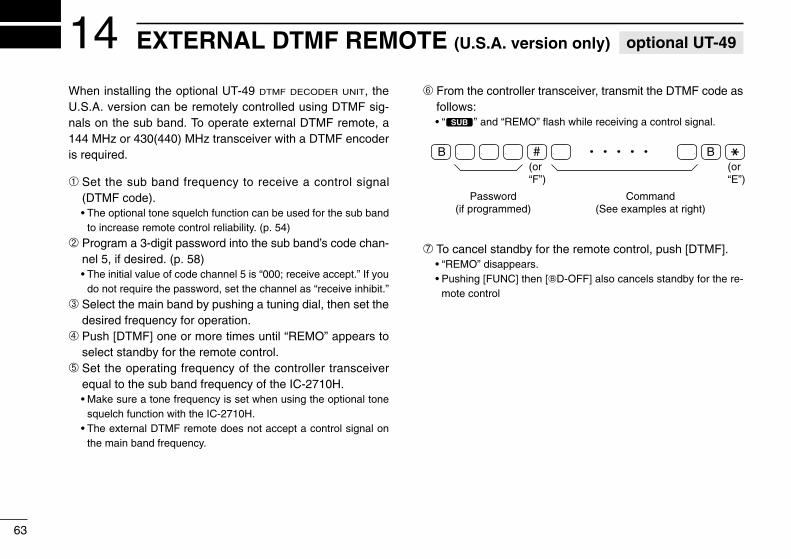
EXTERNAL DTMF REMOTE (U.S.A. version only)14
63
When installing the optional UT-49 DTMF DECODER UNIT, theU.S.A. version can be remotely controlled using DTMF sig-nals on the sub band. To operate external DTMF remote, a144 MHz or 430(440) MHz transceiver with a DTMF encoderis required.
➀ Set the sub band frequency to receive a control signal(DTMF code).• The optional tone squelch function can be used for the sub band
to increase remote control reliability. (p. 54)
➁ Program a 3-digit password into the sub band’s code chan-nel 5, if desired. (p. 58)• The initial value of code channel 5 is “000; receive accept.” If you
do not require the password, set the channel as “receive inhibit.”
➂ Select the main band by pushing a tuning dial, then set thedesired frequency for operation.
➃ Push [DTMF] one or more times until “REMO” appears toselect standby for the remote control.
➄ Set the operating frequency of the controller transceiverequal to the sub band frequency of the IC-2710H.• Make sure a tone frequency is set when using the optional tone
squelch function with the IC-2710H.• The external DTMF remote does not accept a control signal on
the main band frequency.
➅ From the controller transceiver, transmit the DTMF code asfollows:• “#” and “REMO” flash while receiving a control signal.
➆ To cancel standby for the remote control, push [DTMF].• “REMO” disappears.• Pushing [FUNC] then [FD-OFF] also cancels standby for the re-
mote control
Password(if programmed)
(or“F”)
(or“E”)
Command(See examples at right)
B # B M
optional UT-49
IC-2710H.qxd 02.2.8 16:55 Page 63 (1,1)

14EXTERNAL DTMF REMOTE
64
[ENT] 100MHz
10MHz
1 MHz 100kHz
10 kHz3 D 1 4 4
VFOmode
144.750 MHz
CALL MR VFO CLR
[ENT]2 digits
2 D 1 5Memorymode
Memory channel 15
Scratch padmemory 2
7
1 2 3 A
HIGH4 5 6 B
LOW17 8 9 C
UP ENTDOWN
M 0 # D
5
[EXAMPLE]
DTMF KEYPAD
[DOWN] [DOWN]1
Callchannel
M M
[EXAMPLE]: Setting the operating frequency to 145.8125 MHz (when the VHF tuning step is 12.5 kHz).
Note for the [ENT] key• When the entered frequency is outside of the frequency coverage, the input
digits will be cleared.• To adjust the frequency less than 10 kHz or to select a scan edge memory
channel (1A, 1b), use the [UP] or [DOWN] key.
Password(if programmed)
(or “F”) [ENT] (or “E”)(UP)Frequency setting
B 1 2 3 3# D 1 4 5 8VFOmode
# M0 B
IC-2710H.qxd 02.2.8 16:55 Page 64 (1,1)
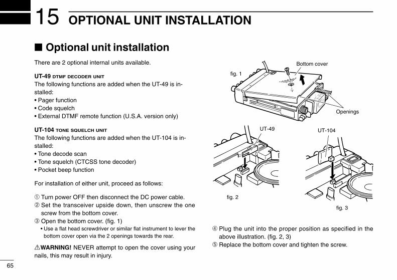
OPTIONAL UNIT INSTALLATION15
65
Optional unit installationThere are 2 optional internal units available.
UT-49 DTMF DECODER UNIT
The following functions are added when the UT-49 is in-stalled:• Pager function• Code squelch• External DTMF remote function (U.S.A. version only)
UT-104 TONE SQUELCH UNIT
The following functions are added when the UT-104 is in-stalled:• Tone decode scan• Tone squelch (CTCSS tone decoder)• Pocket beep function
For installation of either unit, proceed as follows:
➀ Turn power OFF then disconnect the DC power cable.➁ Set the transceiver upside down, then unscrew the one
screw from the bottom cover.➂ Open the bottom cover. (fig. 1)
• Use a flat head screwdriver or similar flat instrument to lever thebottom cover open via the 2 openings towards the rear.
RWARNING! NEVER attempt to open the cover using yournails, this may result in injury.
➃ Plug the unit into the proper position as specified in theabove illustration. (fig. 2, 3)
➄ Replace the bottom cover and tighten the screw.
Bottom cover
fig. 1
fig. 2
fig. 3
Openings
UT-104UT-49
IC-2710H.qxd 02.2.8 16:55 Page 65 (1,1)

WIRELESS OPERATION 16
66
ConnectionWireless remote control is available when the following op-tions are used:• HM-90 WIRELESS MICROPHONE
• EX-1759 INFRARED RECEIVER
The BC-96 MICROPHONE HOLDER is additionally recommendedfor use with the HM-90, since the HM-90’s internal battery re-quires charging.
D Recommended connection
HM-90 WIRELESS MICROPHONE
The HM-90’s internal battery should be charged when the mi-crophone is not being held.
Charging period: 1.5 hrs. with timer(or 8 hrs. when battery is exhausted)
Operating period: 12 hrs (Operation : standby= 1 : 4)
D Charging methodChoose a method from one of the following:
• Connect the cable from the HM-90 to the EX-1759.• Connect the BC-96 and EX-1759; then put the HM-90 into
the BC-96 (refer to the diagram at left).• Use the CP-1 CIGARETTE LIGHTER CABLE to connect the
BC-96 and cigarette lighter socket.
D Turning the wireless remote ON/OFFWhen you use the HM-90 as a wired microphone, turn OFFthe wireless remote control circuit if desired.
LOCK
AFC AFC-OFF PTT-M MW
PGR
CALL1 2 3 A
4 5 6 B
MR VFO CLR
C-SQL DTMF D-OFF
HIGH MID LOW SET
The diagram shows that the wireless remote con-trol function is turned ON.
Dip switch1 2 3 4
ON
OFF
optional EX-1759 and HM-90
IC-2710H EX-1759 BC-96
Use themicrophone’scable
HM-90
IC-2710H.qxd 02.2.8 16:55 Page 66 (1,1)

16 WIRELESS OPERATION
67
EX-1759 installationThe EX-1759 INFRARED RECEIVER can be installed for 2 differ-ent purposes depending on the HM-90 charger. This is be-cause the EX-1759 has both an infrared receiver and amicrophone connector which contains microphone chargingcapabilities.
• When using the BC-96 with external DC inputAttach the EX-1759 to a suitable location for receiving in-frared signals, e.g. sunvisor, etc.
• When using the connector for a microphone chargerAttach the EX-1759 to a suitable location for receiving in-frared signals and where it can be connected to a cable, e.g.the console, etc.
NOTE: DO NOT attach the EX-1759 where it will be sub-ject to direct sunlight as it cannot detect infrared signalsunder such conditions.
(When using BC-96with external DC)
(When using the micconnector for miccharging.)
The installation clip can be oriented in 1 of 4 ways.
EX-1759
• Optional infrared sub receiverAn optional EX-1513 INFRARED SUB RECEIVER is available toincrease the remote control reliablility and extend the control-lable area. Connect the EX-1513 to the inside connector ofthe EX-1759.
NOTE: The supplied microphone, HM-98, can be con-nected and used with the EX-1759, however, the optionalwireless microphone cannot be used in such a case.
IC-2710H.qxd 02.2.8 16:55 Page 67 (1,1)
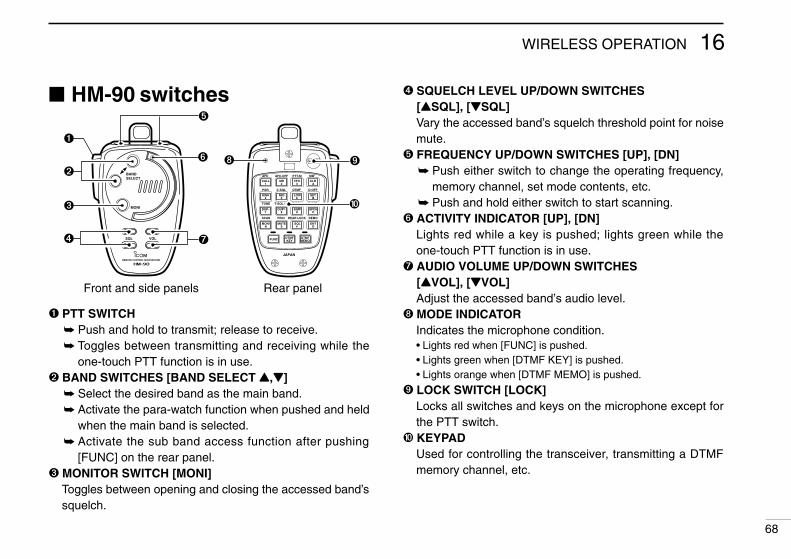
16WIRELESS OPERATION
68
HM-90 switches
PTT SWITCH Push and hold to transmit; release to receive. Toggles between transmitting and receiving while the
one-touch PTT function is in use. BAND SWITCHES [BAND SELECT Y,Z]
Select the desired band as the main band. Activate the para-watch function when pushed and held
when the main band is selected. Activate the sub band access function after pushing
[FUNC] on the rear panel. MONITOR SWITCH [MONI]
Toggles between opening and closing the accessed band’ssquelch.
BANDSELECT
MONI
REMOTE CONTROL MICROPHONE
VOLSQL
LOCK
JAPAN
AFC AFC-OFF PTT-M MW
PGR
CALL1 2 3 A
4 5 6 B
M 0 # D
MR VFO CLR
C-SQL DTMF D-OFF
SCAN
MONI
FUNC DTMFKEY
DTMFMEMO
MUTE SQL ENT
7 8 9 CDUP– DUP+ SIMP SPCH
PRIO REAR LOCK DEMO
TONE
HIGH MID LOW SET
T-SQLS T-SQL T-OFF ➓
Front and side panels Rear panel
SQUELCH LEVEL UP/DOWN SWITCHES[YSQL], [ZSQL]Vary the accessed band’s squelch threshold point for noisemute.
FREQUENCY UP/DOWN SWITCHES [UP], [DN] Push either switch to change the operating frequency,
memory channel, set mode contents, etc. Push and hold either switch to start scanning.
ACTIVITY INDICATOR [UP], [DN]Lights red while a key is pushed; lights green while theone-touch PTT function is in use.
AUDIO VOLUME UP/DOWN SWITCHES[YVOL], [ZVOL]Adjust the accessed band’s audio level.
MODE INDICATORIndicates the microphone condition.• Lights red when [FUNC] is pushed.• Lights green when [DTMF KEY] is pushed.• Lights orange when [DTMF MEMO] is pushed.
LOCK SWITCH [LOCK]Locks all switches and keys on the microphone except forthe PTT switch.
➓ KEYPADUsed for controlling the transceiver, transmitting a DTMFmemory channel, etc.
IC-2710H.qxd 02.2.8 16:55 Page 68 (1,1)
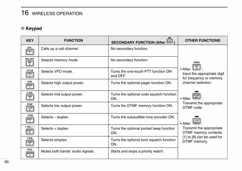
16 WIRELESS OPERATION
69
D Keypad
KEY FUNCTION SECONDARY FUNCTION (After )FUNC OTHER FUNCTIONS
Calls up a call channel. No secondary function.
• After :Input the appropriate digitfor frequency or memorychannel selection.
• After :Transmit the appropriateDTMF code.
• After :Transmit the appropriateDTMF memory contents.[1] to [8] can be used forDTMF memory.
DTMFMEMO
DTMFKEY
DENT
DEMOSelects memory mode. No secondary function.
Selects VFO mode. Turns the one-touch PTT function ONand OFF.
Selects high output power. Turns the optional pager function ON.
Selects mid output power. Turns the optional code squelch functionON.
Selects low output power. Turns the DTMF memory function ON.
Selects – duplex. Turns the subaudible tone encoder ON.
Selects + duplex. Turns the optional pocket beep functionON.
Selects simplex. Turns the optional tone squelch functionON.
Mutes both bands’ audio signals. Starts and stops a priority watch.
AFC
CALL1
AFC-OFF
2MR
PTT-M
3VFO
PGR
4HIGH
5
C-SQL
MID
6
DTMF
LOW
7DUP–
TONE
8DUP+
T-SQLS
9SIMP
T-SQL
0MUTE
PRIO
IC-2710H.qxd 02.2.8 16:55 Page 69 (1,1)

16WIRELESS OPERATION
70
KEY FUNCTION SECONDARY FUNCTION (After )FUNC OTHER FUNCTIONS
Clears a digit before entry.
Cancels the scan, priority watch, pager,code squelch or DTMF memory function.
Writes the VFO contents into the memorychannel or call channel.
Advances the memory channel numberwhen continuously pushed after program-ming is completed.
• After :Transmit the appropriateDTMF code.
[BMONI]Transmits a 1750 Hz tonecall signal for 1 sec.
[ASQL]Transmits a 1750 Hz tonecall signal while pushing.
DTMFKEY
Enters set mode and advances the setmode selection order.
Turns the pager, code squelch, DTMFmemory or DTMF remote function OFF.
Decreases the set mode selection orderafter entering set mode.
NOTE:The IC-2710H has no voice synthesizerfunction.
Turns the subaudible tone encoder, or op-tional pocket beep/tone squelch OFF.
Sets the keypad for numeral input. Enters and exits demonstration mode.
Opens and closes the accessed band’ssquelch.
Starts and stops scanning.
Starts tone scan while an optional tonesquelch is in use.
Selects 1 of the 4 preset squelch levels. Locks all the keys on the microphone key-pad.
MW
ACLR
B
D-OFF
SET
CSPCH
T-OFF
DENT
DEMO
M
SCAN
MONI
#SQL
REAR LOCK
IC-2710H.qxd 02.2.8 16:55 Page 70 (1,1)

16 WIRELESS OPERATION
71
Microphoneaddress
The transceiver has 8 possible microphone addresses to helpprevent interference from other HM-90 WIRELESS MICRO-PHONES. Set both the microphone address and microphonedip switch to the same value as follows.
NOTE: When the supplied microphone is connected, thetransceiver rejects control signals from the HM-90 evenwhen the microphone address is matched.
D Microphone address➀ Push [POWER] to turn power
OFF.➁ While pushing [(VOL)SET L],
turn power ON to enter initialset mode.
➂ Push [SET] a few times to se-lect the “Adr” display asshown at right.
➃ Rotate the left-hand tuning dial to set the microphone ad-dress to 0–7 or to turn the microphone control OFF.• When “Adr-oF” is selected, the transceiver rejects all control sig-
nals from the HM-90.
➄ Turn power OFF to exit initial set mode.
USING INITIAL SET MODE
The display shows the mi-crophone address is set to 1.
D Microphone dip switch➀ Remove the switch cover from the microphone rear panel.➁ Set the microphone dip switch and the microphone ad-
dress to the same value as shown below.➂ Replace the switch cover.
MICROPHONEADDRESS
DIP SWITCH
S1–1 S1–2 S1–3
Adr-0 OFF OFF OFF
Adr-1 (default) ON OFF OFF
Adr-2 OFF ON OFF
Adr-3 ON ON OFF
Adr-4 OFF OFF ON
Adr-5 ON OFF ON
Adr-6 OFF ON ON
Adr-7 ON ON ON
LOCK
AFC AFC-OFF PTT-M MW
PGR
CALL1 2 3 A
4 5 6 B
MR VFO CLR
C-SQL DTMF D-OFF
HIGH MID LOW SET
Dip switch
ON
OFF
1 2 3
(S1)Switch cover
IC-2710H.qxd 02.2.8 16:55 Page 71 (1,1)

OTHER FUNCTIONS 17
72
Beep tones on/offYou can select silent operation by turning beep tones OFF oryou can select to have confirmation beeps sound at the pushof a switch by turning beep tones ON.
➀ Push power to turn power OFF.➁ While pushing [(VOL)SET L], turn power ON to enter initial
set mode.➂ Push [(VOL)SET L] one or more times until “bEP” appears.
• Pushing [(SQL)MONI] reverses the order of selection.
➃ Rotate the left-hand tuning dial to select the condition.• “bEP-oF”: Beep tones are turned OFF.• “bEP-on”: Beep tones are turned ON.
➄ Push [POWER] momentarily to exit initial set mode.
Time-out timerTo prevent accidental prolonged transmission with the one-touch PTT function, etc., the transceiver has a time-out timer.This timer cuts a transmission OFF after 3, 5, 15 or 30 min. ofcontinuous transmission. This timer can be cancelled (de-fault).
Approx. 10 sec. before the time-out timer passes, the trans-ceiver emits a beep tone as a warning.
➀ Push [POWER] to turn power OFF.➁ While pushing [(VOL)SET L], turn power ON to enter initial
set mode.➂ Push [(VOL)SET L] one or more times until “tot” appears.
• Pushing [(SQL)MONI] reverses the order of selection.
➃ Rotate the left-hand tuning dial to select the desired time-out time or turn the timer OFF (“oF”).
➄ Push [POWER] momentarily to exit initial set mode.
USING INITIAL SET MODE USING INITIAL SET MODE
The display shows that beep tones are turned ON.
The display shows that the 5 min. timer is selected.
TOT
The display shows that the time-out timer is cancelled.
IC-2710H.qxd 02.2.8 16:55 Page 72 (1,1)

17 OTHER FUNCTIONS
73
Auto power-offThe auto power-off function conveniently turns the transceiverpower OFF after a preset time in which no operations are per-formed. In this way, when you forget to turn the power OFF,the transceiver automatically turns itself OFF, thereby con-serving battery power.
The time can be set to 30 min., 1 hr., 2 hr. or turned OFF. Theselected time is retained even when the transceiver is turnedOFF via the auto power-off function. To cancel the function,select “oF” in step ➃ below.
➀ Push [POWER] to turn powerOFF.
➁ While pushing [(VOL)SET L],turn power ON to enter initialset mode.
➂ Push [(VOL)SET L] one ormore times until “PoF” appears.• Pushing [(SQL)MONI] reverses the order of selection.
➃ Rotate the left-hand tuning dial to select the desired autopower-off time or turn the timer OFF (“oF”).• “AO” appears when an auto power-off time is set.
➄ Push [POWER] momentarily to exit initial set mode.
Cooling fansetting
The transceiver has a heatsink and cooling fan to radiateheat. The cooling fan automatically turns ON while transmit-ting and remains ON for 2 min. after transmitting. The cool-ing fan can be activated continuously, if desired.
➀ Push power to turn power OFF.➁ While pushing [(VOL)SET L], turn power ON to enter initial
set mode.➂ Push [(VOL)SET L] one or more times until “FAn” appears.
• Pushing [(SQL)MONI] reverses the order of selection.
➃ Rotate the left-hand tuning dial to set the cooling fan to au-tomatic (“At”) or continuous (“on”).
➄ Push [POWER] momentarily to exit initial set mode.
USING INITIAL SET MODE USING INITIAL SET MODE
The display shows that the 30 min. timer is selected.
A O
The display shows that the cooling fan is set for au-tomatic operation.
The display shows that the cooling fan is set for contin-uous operation.
IC-2710H.qxd 02.2.8 16:55 Page 73 (1,1)
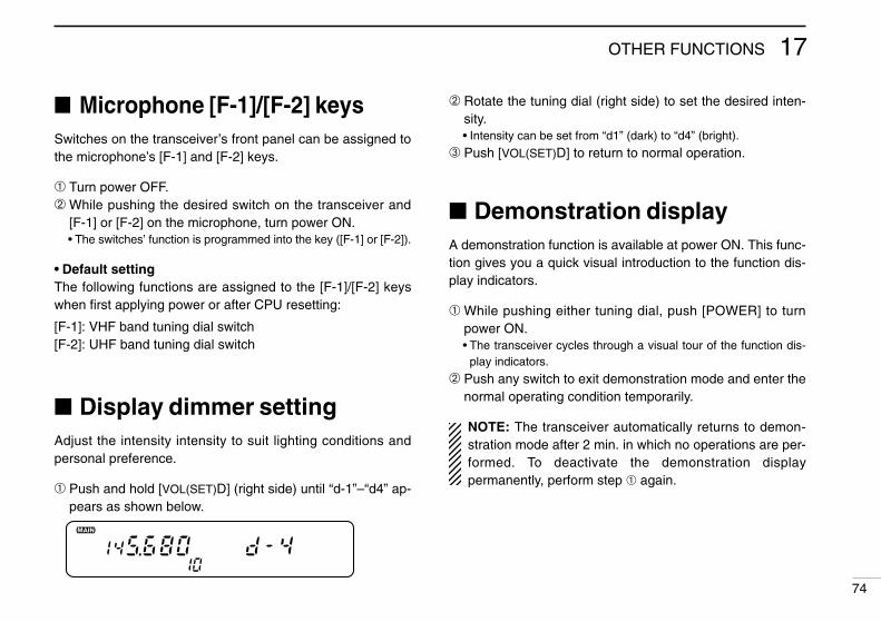
17OTHER FUNCTIONS
74
Microphone [F-1]/[F-2] keysSwitches on the transceiver’s front panel can be assigned tothe microphone’s [F-1] and [F-2] keys.
➀ Turn power OFF.➁ While pushing the desired switch on the transceiver and
[F-1] or [F-2] on the microphone, turn power ON.• The switches’ function is programmed into the key ([F-1] or [F-2]).
• Default settingThe following functions are assigned to the [F-1]/[F-2] keyswhen first applying power or after CPU resetting:
[F-1]: VHF band tuning dial switch[F-2]: UHF band tuning dial switch
Display dimmer settingAdjust the intensity intensity to suit lighting conditions andpersonal preference.
➀ Push and hold [VOL(SET)D] (right side) until “d-1”–“d4” ap-pears as shown below.
➁ Rotate the tuning dial (right side) to set the desired inten-sity.• Intensity can be set from “d1” (dark) to “d4” (bright).
➂ Push [VOL(SET)D] to return to normal operation.
Demonstration displayA demonstration function is available at power ON. This func-tion gives you a quick visual introduction to the function dis-play indicators.
➀ While pushing either tuning dial, push [POWER] to turnpower ON.• The transceiver cycles through a visual tour of the function dis-
play indicators.
➁ Push any switch to exit demonstration mode and enter thenormal operating condition temporarily.
NOTE: The transceiver automatically returns to demon-stration mode after 2 min. in which no operations are per-formed. To deactivate the demonstration displaypermanently, perform step ➀ again.
9
IC-2710H.qxd 02.2.8 16:55 Page 74 (1,1)

MAINTENANCE18
75
Troubleshooting If your transceiver seems to be malfunctioning, please checkthe following points before sending it to a service center.
PROBLEM POSSIBLE CAUSE SOLUTION REF.
No power comes on. • Power connector has a poor contact.• Polarity of the power connection is reversed.
• Blown fuse.
• Check the connector pins.• Reconnect the power cable observing the proper
polarity. Replace the fuse, if damaged.• Check the cause, then replace the fuse.
—pgs.13, 77p. 77
No sound comes from thespeaker.
• Volume level is too low.• The squelch level is set too tight.• An optional selective call or squelch function is
activated such as tone squelch, pocket beep,pager or code squelch.
• Rotate [VOL] clockwise.• Set the squelch level to the threshold.• Turn the appropriate function OFF.
p. 20p. 20
pgs.53, 54,59, 62
Sub band signals are not au-dible.
• The sub band mute function is activated. • Turn the function OFF. p. 23
Sensitivity is low and onlystrong signals are audible.
• Antenna feedline or the antenna connector sol-der has a poor contact or is short circuited.
• Check, and if necessary, replace the feedline orsolder the antenna connector again.
p. 14
No contact possible with an-other station.
• The transceiver is set to semi-duplex.• The other station is using code or tone squelch.
• Set to simplex.• Turn ON the optional code squelch (UT-49) or
optional tone squelch (UT-104 ).
p. 28pgs.62, 54
Repeater cannot be ac-cessed.
• Wrong offset frequency is programmed.• Wrong subaudible tone frequency is pro-
grammed.
• Correct the offset frequency.• Correct the subaudible tone frequency.
p. 30p. 29
Frequency cannot be set. • The frequency lock function is activated.• Priority watch is paused on the watching fre-
quency.
• Turn the function OFF.• Push [(M/CALL)PRIO] to resume the watch.
p. 16p. 48
IC-2710H.qxd 02.2.8 16:55 Page 75 (1,1)

18MAINTENANCE
76
PROBLEM POSSIBLE CAUSE SOLUTION REF.
Frequency cannot be set viamicrophone.
• The frequency lock function is activated.
• The microphone keypad lock function is acti-vated.
• Priority watch is paused on the watching fre-quency.
• Push and hold [(VFO)LOCK] to deactivate thefrequency lock function.
• Push [FUNC], then [A16KEY LOCK] to deacti-vate the microphone keypad lock function.
• Push the selected band’s [(M/CALL)PRIO] to re-sume the watch.
p. 16
p. 16p. 48
Some memory channelscannot be selected via themicrophone keypad.
• The input channel number has not yet been pro-grammed.
• Rotate the tuning dial to check whether thechannel has been programmed or not.
p. 32
Scan does not operate. • Squelch is open.• The selected scan edge memory channels (e.g.
1 A and 1b) have the same frequencies (for pro-grammed scan).
• Only 1 memory channel is programmed or otherchannels are set as skip channels.
• Priority watch is activated.
• Set the squelch to the threshold point.• Reset the scan edges.
• Program other memory channels or cancel thememory skip function in the desired channels.
• Turn the function OFF.
p. 20p. 43
pgs.33, 45p. 48
Transmission is automati-cally cut off.
• Time-out timer is activated. • Set the timer to OFF. p. 72
Transmission continueseven when the PTT is re-leased.
• One-touch PTT function is activated. • Turn the function OFF. p. 26
The function display showserroneous information.
• The CPU is malfunctioning. • Reset the transceiver. p. 77
IC-2710H.qxd 02.2.8 16:55 Page 76 (1,1)
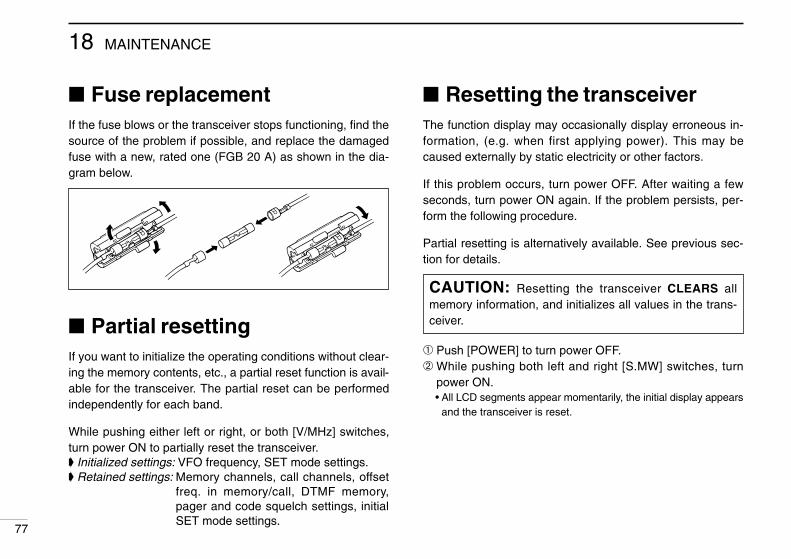
18 MAINTENANCE
77
Fuse replacementIf the fuse blows or the transceiver stops functioning, find thesource of the problem if possible, and replace the damagedfuse with a new, rated one (FGB 20 A) as shown in the dia-gram below.
Partial resettingIf you want to initialize the operating conditions without clear-ing the memory contents, etc., a partial reset function is avail-able for the transceiver. The partial reset can be performedindependently for each band.
While pushing either left or right, or both [V/MHz] switches,turn power ON to partially reset the transceiver. Initialized settings: VFO frequency, SET mode settings. Retained settings: Memory channels, call channels, offset
freq. in memory/call, DTMF memory,pager and code squelch settings, initialSET mode settings.
Resetting the transceiverThe function display may occasionally display erroneous in-formation, (e.g. when first applying power). This may becaused externally by static electricity or other factors.
If this problem occurs, turn power OFF. After waiting a fewseconds, turn power ON again. If the problem persists, per-form the following procedure.
Partial resetting is alternatively available. See previous sec-tion for details.
➀ Push [POWER] to turn power OFF.➁ While pushing both left and right [S.MW] switches, turn
power ON.• All LCD segments appear momentarily, the initial display appears
and the transceiver is reset.
CAUTION: Resetting the transceiver CLEARS allmemory information, and initializes all values in the trans-ceiver.
IC-2710H.qxd 02.2.8 16:55 Page 77 (1,1)

SPECIFICATIONS 19
78
General• Frequency coverage
VERSION VHF UHF144–148 MHz
440–450 MHz
Asia144–148 MHz
430–440 MHz
Europe 144–146 MHz 430–440 MHz
Italy144–146 MHz 430–440 MHz
TxRx 136–174 MHz*2
TxRx 136–174 MHz*2 400–479 MHz*3
*1118–136 MHz is usable in the VHF display only; guaranteed frequency cov-erage is 144–148 MHz.
*2Guaranteed frequency coverage is 144–148 MHz.*3Guaranteed frequency coverage is 430–440 MHz.
• Mode : FM, AM*(*U.S.A. version only; 118–136 MHz)
• Antenna impedance : 50 Ω (SO-239)• Power supply requirement : 13.8 V DC ± 15%• Usable temperature range : –10°C to +60°C; +14°F to +140°F• Dimensions : 140(W) x 40(H) x 212.4(D) mm
(projections not included) 51⁄2(W) x 19⁄16(H) x 83⁄8(D) in• Weight : 1.4 kg; 3.1 lb
Transmitter• Modulation system : Variable reactance frequency
modulation• Max. frequency deviation : ± 5.0 kHz• Spurious emissions : Less than –60 dB• Microphone impedance : 600 Ω (8-pin modular)
• Output power and current drain:
Receiver• Receive system : Double conversion superheterodyne• Intermediate frequencies :
Left display band 1st 45.05 MHz 2nd 455 kHzRight display band 1st 57.65 MHz 2nd 455 kHz
• Sensitivity (for 12 dB SINAD) : Less than 0.16 µV (incl. para watch)
• Squelch sensitivity : Less than 0.13 µV (at threshold)
• Selectivity : More than 15 kHz/–6 dBLess than 30 kHz/–60 dB
• Spurious response : More than 60 dBrejection ratio
• Audio output power : More than 2.4 W at 10% distortionwith the 8 Ω internal speaker
• Current drain :Max rated audio/both bands 1.8 AMax audio/either band 1.5 A (squelch closed on other band)
Squelched on both bands 1.2 A
CONDITION POWER
144 MHz
50 W10 W
5 W
430(440) MHz
12.0 A6.5 A4.5 A
11.0 A35 W10 W 6.5 A
5 W 4.5 A
High
LowMid
HighMidLow
All stated specifications are subject to change without notice orobligation
CURRENT
U.S.A.118–174 MHz*1Rx
Tx
IC-2710H.qxd 02.2.8 16:55 Page 78 (1,1)

OPTIONS20
79
Some of the following options may not be available due tovariations in local electrical standards, etc. If you have anyquestions regarding options please consult your Icom Dealer.
D AntennaAH-32 144/430(440) MHz DUAL BAND ANTENNADual band mobile antenna.Frequency range: 144–148 MHz and 430–450 MHz.Max. input power: 150 WAHB-32 TRUNK MOUNTTrunk mount with a coaxial cable for the AH-32.
D SpeakersSP-7 EXTERNAL SPEAKERFor base station use. Cable length: 1.0 m; 3.3 ft
SP-10 EXTERNAL SPEAKERCompact design. Cable length: 1.5 m; 4.9 ft
SP-12 EXTERNAL SPEAKERSlim-type. Cable length: 2.0 m; 6.6 ft
D Separation accessoriesOPC-600/601 SEPARATION CABLEFor operation with the front panel detached.Cable lengthOPC-600: 3.5 m; 11.5 ft OPC-601: 7.0 m; 23.0 ftMB-58 REMOTE CONTROLLER BRACKETMounts the remote controller in a convenient location for op-eration with the front panel detached from the main body.MB-65 REMOTE CONTROLLER BRACKETMounts the remote controller with MB-58. Adjustable angleand direction for optimum installation positioning.OPC-440/647 MIC EXTENSION CABLECable lengthOPC-440: 5.0 m; 16.4 ft OPC-647: 2.5 m; 8.2 ft.OPC-347 DC POWER CABLEHas a 20 A capacity and a length of 7.0 m (23.0 ft).OPC-441 SPEAKER EXTENSION CABLECable length: 5.0 m; 16.4 ft.
SP-7 SP-10 SP-12 MB-65
IC-2710H.qxd 02.2.8 16:55 Page 79 (1,1)

20OPTIONS
80
D Wireless microphone accessoriesHM-90 WIRELESS MICROPHONEInfrared, full remote control microphone. Wired remote con-trol is also possible.EX-1759 INFRARED RECEIVERUsed to receive control signals from the HM-90.EX-1513 INFRARED SUB RECEIVERUsed with the EX-1759 to increase remote control reliabilityand extend the controllable area.BC-96 MICROPHONE HOLDERHolds the HM-90 body in a convenient place and suppliespower to the charging circuit of the HM-90. Has a chargingindicator.CP-13/L CIGARETTE LIGHTER CABLE WITH NOISE FILTEROPC-288/L DC POWER CABLESupply power to the BC-96 for charging the Ni-Cd battery in-side the HM-90 when the BC-96 cannot be connected to theEX-1759 directly.
D Internal units for function enhancementsUT-49 DTMF DECODER UNITProvides pager and code squelch functions. Also provides anexternal DTMF function for the U.S.A. version only.UT-104 TONE SQUELCH UNITProvides pocket beep, tone squelch and tone scan functions.
D OthersMB-17A MOBILE MOUNTING BRACKETOne-touch bracket. Transceiver body is easily attached andremoved.IC-PS30 DC POWER SUPPLYProvides 13.8 V DC and 25 A max. for base station use.CS-2710 CLONING SOFTWARE + OPC-646 CLONING CABLEProvides quick and easy programming of items, includingmemory channels and set mode contents, for local repeaterfrequencies, etc.
HM-90
BC-96 MB-17A
IC-2710H.qxd 02.2.8 16:55 Page 80 (1,1)

MODE ARRANGEMENT21
81
MEMORY MODE (p. 32)
VFO MODE (p. 15)
CALL CHANNEL (p. 37)
SCRATCH PADMEMORY (p. 39)
See p. 49 for details.
DTMF MEMORY
CODE CHANNEL
Used for programming the code channel for pager and code squelch (p. 57).
M/CALL
V/MHzSCAN
V/MHzSCAN
SET L
or no operation for 30 sec.
SEL L
*1Only appears*2Only appears
Whe
n th
e D
TM
F
mem
ory
enco
der
is
activ
ated
.
Whe
n th
e pa
ger
or c
ode
sque
lch
is in
use
.
M/CALL
Although the following chart refers mainly to the VHF band, the transceiver has the samemode arrangement in the UHF band.
IC-2710H.qxd 02.2.8 16:55 Page 81 (1,1)

Y
CHANNEL
r programming e channel for d code squelch
INITIAL SET MODESET MODE
MONISEL L
SEL L
Sub band mute (p. 23)SKIP
Skip channel*2
setting (p. 45)
Beep tone on/off (p. 72)
Turn power ON while pushing [SET L].
Time-out timer (p. 72)
Auto power-off (p. 73)
DUP T
Auto repeater* (p. 31)
* U.S.A. version only.
Cooling fan setting (p. 73)
Microphone address (p. 74)
MONI
DTMF speed (p. 52)
Offset frequency(p. 30)
DUP
Scan resumecondition (p. 46)
Tuning step*1
(p. 18)
Subaudible tonefrequency (p. 29)
T
*1Only appears when entering SET mode from VFO mode.*2Only appears when entering SET mode from memory mode.
activ
ated
.
Whe
n th
e pa
ger
or c
ode
sque
lch
is in
use
.
21MODE ARRANGEMENT
82
IC-2710H.qxd 02.2.8 16:55 Page 82 (1,1)

1-1-32 Kamiminami, Hirano-ku, Osaka 547-0003 Japan
A-5382H-1EXPrinted in JapanCopyright © 1996 by Icom Inc.
Count on us!
IC-2710H.qxd 02.2.8 16:55 Page 83 (1,1)