iBot Club Line follower tutorial
22
iBot Club Line follower tutorial Basic electrical and arduino coding Created by: Spoorthy and Sowmya
Transcript of iBot Club Line follower tutorial

iBot ClubLine follower tutorialBasic electrical and arduino coding
Created by:Spoorthy and Sowmya


Breadboard

The horizontal holes on each side of the breadboard are connected together. Anything plugged into these holes will be connected together. The horizontal holes on one
side are not connected to those on the other.

The first five and the last five vertical strips are electrically connected. The outer strip is usually used as 5V and the inner ones as GND. Usually the first five and
the last five strips are joined by wire.

IR Sensors

IR LED
Phototransistor
12 VOutputHow does it work?
• The IR LED transmits light in the IR region. Phototransistor makes output 5V if light in the IR region falls on it. Else, it gives 0V.
• So, if there is a reflecting obstacle (like white chart paper) present in front of the sensor, the IR light is reflected and falls on the phototransistor and the output is 5V.
• If there is no obstacle or a non-reflecting obstacle like black tape present in front of the LED, no IR light falls on the phototransistor and the output is 0V.

Converting 12 V to 5V• 7805T IC is used for this.• Every IC has a datasheet which tells you how to
use it.• This is the pin out given in the datasheet for the
7805T IC.• When one looks at it with bulge on it towards
them, the left pin is the input of 12 V, the centre ground and the right pin output of 5V.

Constructing the motor driver circuit
We use L293D motor driver IC for this.


• All the GNDs must be connected to ground.• Vss is the power supply to the IC. It must be connected to 5V.• Vs is the voltage to be redirected to the outputs.• If an input is supplied with 5V, the corresponding output is Vs. • If an input is supplied with GND, the corresponding output is GND.• If Enable 1 is connected to 5V, outputs 1 & 2 are enabled. Enable
2 corresponds to outputs 3 & 4. • Bot moves forward, if the inputs from arduino are input1,input4-
HIGH and input3,input-5-LOW and in the reverse manner for backward motion.

Making connections on the breadboard
• Single strand wires are used for connections. • Connections must be tight.• No wire without insulation must be seen on the bread board.
• 5V connections are in Red.
• GND connections are in Black.
• Other connections are in any other colour.

L293D
Left Sensor’s O/P
Right Sensor’s O/P
L M
R M
Notice the cut is on the right

Arduino Coding
Structure:
Initialization :
Initialize the pins that are connected.
Ex: int led=13
The above statement explains that pin 13 is attached to an led

setup()
The setup() function is called when a sketch starts. Use it to initialize variables, pin
modes, start using libraries, etc. The setup function will only run once, after each powerup or reset of
the Arduino board.
loop()After creating a setup() function, which initializes and sets the initial values, the loop() function does
precisely what its name suggests, and loops consecutively, allowing your program to change and
respond. Use it to actively control the Arduino board.

Example:
int buttonPin = 3;
void setup()
{
Serial.begin(9600);
pinMode(buttonPin, INPUT);
}
void loop()
{
// ...
}

Basic Functions:
pinMode()Configures the specified pin to behave either as an input or an output.
SyntaxpinMode(pin, mode)
Parameterspin: the number of the pin whose mode you wish to set
mode: INPUT, OUTPUT, or INPUT_PULLUP.
ReturnsNone
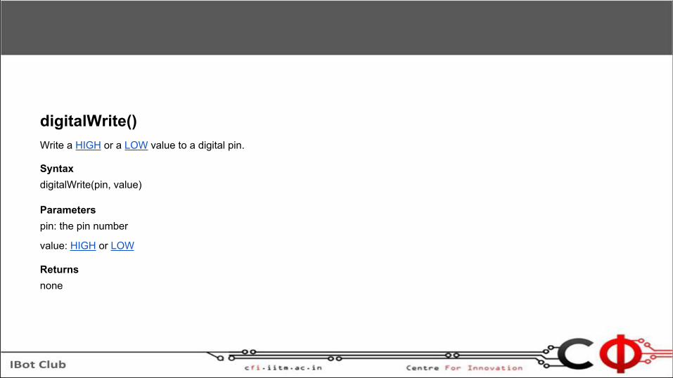
digitalWrite()Write a HIGH or a LOW value to a digital pin.
SyntaxdigitalWrite(pin, value)
Parameterspin: the pin number
value: HIGH or LOW
Returnsnone

digitalRead()Reads the value from a specified digital pin, either HIGH or LOW.
SyntaxdigitalRead(pin)
Parameterspin: the number of the digital pin you want to read (int)
ReturnsHIGH or LOW

analogRead()Reads the value from the specified analog pin. The Arduino board contains a 6 channel (8 channels on the Mini and Nano, 16 on the Mega), 10-bit analog to digital converter. This means that it will map input voltages between 0 and 5 volts into integer values between 0 and 1023. This yields a resolution between readings of: 5 volts / 1024 units or, .0049 volts (4.9 mV) per unit. The input range and resolution can be changed using analogReference().
It takes about 100 microseconds (0.0001 s) to read an analog input, so the maximum reading rate is about 10,000 times a second.
SyntaxanalogRead(pin)
Parameterspin: the number of the analog input pin to read from (0 to 5 on most boards, 0 to 7 on the Mini and Nano, 0 to 15 on the Mega)
Returnsint (0 to 1023)

analogWrite()Writes an analog value (PWM wave) to a pin. Can be used to light a LED at varying brightnesses or drive a motor at various speeds. After a call to analogWrite(), the pin will generate a steady square wave of the specified duty cycle until the next call to analogWrite() (or a call to digitalRead() or digitalWrite() on the same pin)
SyntaxanalogWrite(pin, value)
Parameterspin: the pin to write to.
value: the duty cycle: between 0 (always off) and 255 (always on).
Returnsnothing