
D-Link Cloud Revolutions DIR-605L DCS-930L DCS-932L DCS-942LDCS-1130L DCS-5222L DNR-322L.

IBM System Storage DS3000, DS4000, DS5000, and theDCS Series
Hard Disk Drive and Storage EnclosureInstallation and Migration Guide
GA32-0962-06
IBM

NoteBefore using this information and the product it supports, be sure to read the general information in “Notices andstatements in this document” on page x and “Notices” on page 151.
This edition applies to version 10 modification 60 of the IBM DS Storage Manager, and to all subsequent releasesand modifications until otherwise indicated in new editions.
This edition replaces GA32-0962-05.
© Copyright IBM Corporation 2008, 2013.US Government Users Restricted Rights – Use, duplication or disclosure restricted by GSA ADP Schedule Contractwith IBM Corp.

Contents
Figures . . . . . . . . . . . . . .. v
Tables . . . . . . . . . . . . . .. vii
Introduction . . . . . . . . . . . .. ixSupported IBM System Storage DS and DCS Seriesstorage systems . . . . . . . . . . . .. ixWhat's new in this guide . . . . . . . . .. ixReceiving product updates and support notifications ixDS Storage Subsystem installation and supportguides . . . . . . . . . . . . . . .. xNotices and statements in this document . . . .. x
Chapter 1. Prerequisites to addingcapacity and hard disk drive migration . 1Preparing the storage subsystem. . . . . . .. 1Preparing to export and import drives . . . . .. 3Determining the supported number of drives anddrive loop pairs . . . . . . . . . . . .. 4Verifying controller, NVSRAM, and ESM firmwarecompatibility . . . . . . . . . . . . .. 9
Storage subsystem profile. . . . . . . .. 13Physical View pane . . . . . . . . . .. 13
Upgrading ESM and controller firmware . . .. 14Drive migration limitations . . . . . . . .. 15Verifying hard disk drive model compatibility . .. 17Viewing the product ID and model of a hard diskdrive . . . . . . . . . . . . . . .. 19Bringing storage subsystems and drive loops intooptimal state . . . . . . . . . . . . .. 21Intermixing storage enclosures . . . . . . .. 21
Setting enclosure IDs for enclosures in DS4000and DS5000 storage subsystems . . . . .. 29DS4000 Fibre Channel and Serial ATA Intermixpremium feature. . . . . . . . . . .. 31Intermixing EXP100 and EXP710 storageenclosures . . . . . . . . . . . . .. 32Intermixing EXP395 and EXP810 storageenclosures . . . . . . . . . . . . .. 37Intermixing EXP520 and EXP810 storageenclosures . . . . . . . . . . . . .. 37Intermixing EXP810 with EXP100 and EXP710storage enclosures . . . . . . . . . .. 38Intermixing EXP810 and EXP5000 storageenclosures . . . . . . . . . . . . .. 43Intermixing EXP5000 and EXP5060 storageenclosures . . . . . . . . . . . . .. 43Intermixing storage enclosures for DS4000 andDS5000 storage subsystems . . . . . . .. 44
Chapter 2. Adding or migrating harddisk drives . . . . . . . . . . . .. 57Considerations . . . . . . . . . . . .. 57Handling static-sensitive devices . . . . . .. 58
Adding new hard disk drives . . . . . . .. 58Migrating hard disk drives . . . . . . . .. 59
Step 1: Preliminary activities. . . . . . .. 60Step 2: Verifying drive migration enable settings 61Step 3: Placing drives offline. . . . . . .. 62Step 4: Removing drives . . . . . . . .. 63Step 5: Inserting drives . . . . . . . .. 64
Migrating arrays within the same storage subsystem 66Using the drive migration disable script to add newdrives . . . . . . . . . . . . . . .. 70
Step 1: Disabling the drive migration settings .. 70Step 2: Inserting drives . . . . . . . .. 71Step 3: Re-enabling the drive migration settings 71
Chapter 3. Adding or migrating storageenclosures . . . . . . . . . . . .. 75Considerations . . . . . . . . . . . .. 75Step 1: Preliminary activities. . . . . . . .. 77
Adding new storage enclosures with new harddisk drives . . . . . . . . . . . .. 78Migrating storage enclosures with hard diskdrives that have defined logical driveconfigurations . . . . . . . . . . .. 79
Step 2: Preparing and backing up the drives . .. 80Step 3: Shutting down and moving the storageenclosures . . . . . . . . . . . . . .. 81Step 4: Verifying the drive migration enable settings 82Step 5: Installing and setting storage enclosure IDsand speeds . . . . . . . . . . . . .. 83Step 6: Cabling, turning on, and verifying storageenclosure operation. . . . . . . . . . .. 84
Cabling the new enclosures . . . . . . .. 84Connecting storage enclosures at the end(bottom) of a drive loop . . . . . . . .. 86Connecting storage enclosures in the middle of adrive loop . . . . . . . . . . . . .. 92Connecting storage enclosures at the beginning(top) of a drive loop . . . . . . . . .. 97Returning the drive/loop channel to optimalstate . . . . . . . . . . . . . .. 102DS4000 and DS5000 storage subsystem FibreChannel drive loop schemes . . . . . .. 103Storage subsystem SAS drive channel/loopschemes for enclosures in a DS3000 or DS3500configuration . . . . . . . . . . .. 107Storage subsystem SAS drive channel/loopschemes for enclosures in a DCS3700 or in aDCS3700 with Performance Module Controllersconfiguration . . . . . . . . . . .. 108Cabling EXP100, EXP710, and EXP810 storageenclosures in DS4700 and DS4800 configurations 110
Step 7: Inserting drives and cabling additionalstorage enclosures . . . . . . . . . . .. 113Step 8: Inserting hard disk drives and placinglogical drives online . . . . . . . . . .. 114
© Copyright IBM Corp. 2008, 2013 iii

Chapter 4. Upgrading a storagesubsystem controller . . . . . . .. 117Upgrade considerations . . . . . . . . .. 117
Host attachment and premium featureentitlements . . . . . . . . . . . .. 117Storage firmware migration. . . . . . .. 118Alternative procedure to upgrade a storagesubsystem controller enclosure . . . . .. 119Supported upgrades . . . . . . . . .. 120Configuration behavior after an upgrade andstorage subsystem replacement . . . . .. 125Storage subsystem behavior when turning onthe power with no drives attached . . . .. 128
Performing an upgrade . . . . . . . . .. 128Performing an upgrade from a DS4700 or DS4800storage subsystem to a DS5000 storage subsystem . 136Redeploying the original storage subsystem . .. 144
Redeployment limitations . . . . . . .. 144Configuration behavior in a redeployed storagesubsystem . . . . . . . . . . . .. 144
Appendix. Getting information, help,and service . . . . . . . . . . .. 147Before you call . . . . . . . . . . . .. 147Using the documentation . . . . . . . .. 147Finding Storage Manager software, controllerfirmware, and readme files . . . . . . . .. 147Getting help and information from the World WideWeb . . . . . . . . . . . . . . .. 148
Software service and support . . . . . . .. 149Hardware service and support . . . . . .. 149Taiwan Contact Information . . . . . . .. 149Fire suppression systems . . . . . . . .. 149
Notices . . . . . . . . . . . . .. 151Trademarks . . . . . . . . . . . . .. 153Important notes . . . . . . . . . . .. 154Particulate contamination . . . . . . . .. 155Documentation format . . . . . . . . .. 155Electronic emission notices . . . . . . . .. 156
Federal Communications Commission Statement 156Industry Canada Compliance Statement . .. 156Australia and New Zealand Class A Statement 156European Union Electromagnetic CompatibilityDirective . . . . . . . . . . . . .. 156Taiwan Class A Statement . . . . . . .. 157Germany Electromagnetic CompatibilityDirective . . . . . . . . . . . . .. 157People's Republic of China Class A Statement 158Japan Voluntary Control Council for InterferenceClass A Statement . . . . . . . . . .. 158Japan Electronics and Information TechnologyIndustries Association Statement . . . . .. 159Korean Communications Commission Class AStatement . . . . . . . . . . . .. 159
Index . . . . . . . . . . . . . .. 161
iv IBM System Storage DS and DCS Series Hard Disk Drive and Storage Enclosure Installation and Migration Guide

Figures
1. Supported intermixed EXP100 and EXP710storage enclosure loop configuration (1 of 3) . 33
2. Supported intermixed EXP100 and EXP710storage enclosure loop configuration (2 of 3) . 34
3. Supported but not best practice intermixedEXP100 and EXP710 storage enclosure loopconfiguration (3 of 3) . . . . . . . .. 35
4. Unsupported intermixed EXP100 and EXP710storage enclosure loop configuration (1 of 2) . 36
5. Unsupported intermixed EXP100 and EXP710storage enclosure loop configuration (2 of 2) . 37
6. Supported intermixed DS4000 storagesubsystem connected to EXP710 and EXP810storage enclosure loop configuration . . .. 41
7. Supported intermixed DS4000 storagesubsystem connected to EXP710 and EXP810storage enclosure loop configuration . . .. 42
8. Best practice intermixed DS4000 storagesubsystem connected to EXP710 and EXP810storage enclosure loop configuration . . .. 43
9. Best practice intermixed EXP5000 and EXP5060storage enclosure drive/loop cableconfiguration . . . . . . . . . . .. 44
10. Use all drive channel ports when connectingstorage enclosures . . . . . . . . .. 45
11. Use all drive channel ports when connectingstorage enclosures . . . . . . . . .. 47
12. Supported cabling for an intermix of EXP100,EXP710, and EXP810 storage enclosures(example 1) . . . . . . . . . . .. 49
13. Supported cabling for an intermix of EXP100,EXP710, and EXP810 storage enclosures(example 2) . . . . . . . . . . .. 50
14. Unsupported cabling for an intermix ofEXP100, EXP710, and EXP810 storageenclosures (example 1) . . . . . . . .. 51
15. Unsupported cabling for an intermix ofEXP100, EXP710, and EXP810 storageenclosures (example 2) . . . . . . . .. 52
16. Supported cabling to EXP420/EXP520/EXP810/EXP5000 storage enclosure port 1B .. 53
17. Unsupported cabling to theEXP420/EXP520/EXP810/EXP5000 storageenclosure port. . . . . . . . . . .. 54
18. Supported cabling to the EXP500/EXP100/EXP700/EXP710 storage enclosure ports . .. 55
19. Subsystem Management Logical/PhysicalView of exported drives . . . . . . .. 63
20. Drive CRU assembly . . . . . . . .. 6421. Best practice for reordering a defined array by
using empty bays in one storage enclosure .. 6722. Best practice for reordering a defined array by
using empty bays in two storage enclosures.. 6723. Reordering multiple defined arrays across
previously used bays in two storage enclosures 68
24. Subsystem Management Logical/PhysicalView of missing logical drives (controllerfirmware 7.xx.xx.xx or later) . . . . . .. 68
25. Subsystem Management Logical/PhysicalView of missing logical drives (controllerfirmware before 7.xx.xx.xx) . . . . . .. 69
26. EXP100, EXP500, EXP700, EXP710,EXP395/EXP420/EXP520/EXP810/EXP5000storage enclosure ID and speed switches . .. 79
27. Example of adding storage enclosure positionswithin a drive loop . . . . . . . . .. 85
28. Cabling an additional EXP700/EXP710/EXP100/EXP500 storage enclosure . . . .. 89
29. Cabling an additional EXP5000, EXP520,EXP395, EXP810, or EXP420 storage enclosure . 90
30. Cabling an additional EXP3000, EXP3512, orEXP3524 storage enclosure . . . . . .. 91
31. Cabling an additional EXP5060 storageenclosure . . . . . . . . . . . .. 92
32. Cabling an additional storage enclosure to themiddle of the drive loop in a DS5000 storagesubsystem . . . . . . . . . . . .. 96
33. Cabling an additional storage enclosure to themiddle of the drive loop in a DS3000 storagesubsystem configuration . . . . . . .. 97
34. Cabling an additional storage enclosure to thetop of the drive loop in a DS5000 storagesubsystem configuration . . . . . . .. 101
35. Cabling an additional storage enclosure to thetop of the drive loop in a DS3000 storagesubsystem configuration . . . . . . .. 102
36. Best practice cable loop scheme forconnecting storage devices . . . . . .. 103
37. Alternative cable loop scheme for connectingstorage devices . . . . . . . . . .. 104
38. Alternative cable loop scheme for connectingstorage devices . . . . . . . . . .. 105
39. Unsupported cable loop scheme forconnecting storage devices (1 of 2) . . .. 106
40. Unsupported cable loop scheme forconnecting storage devices (2 of 2) . . .. 107
41. Supported EXP710, EXP810, and EXP100storage enclosure intermix configuration in aDS4700 or DS4800 storage subsystem . .. 111
42. Unsupported EXP710, EXP810, and EXP100storage enclosure intermix configuration in aDS4700 or DS4800 storage subsystem . .. 112
43. Cabling variations when EXP100, EXP710,and EXP810 storage enclosures are intermixedbehind a DS4800 storage subsystem . . .. 113
44. Firmware compatibility flowchart for astorage subsystem upgrade . . . . . .. 131
45. Firmware compatibility flowchart for astorage subsystem upgrade (continued) . .. 132
© Copyright IBM Corp. 2008, 2013 v
46. Firmware compatibility flowchart for aDS4700 or DS4800 to a DS5000 storagesubsystem upgrade . . . . . . . .. 140
vi IBM System Storage DS and DCS Series Hard Disk Drive and Storage Enclosure Installation and Migration Guide

Tables
1. Supported drives and drive loop pairs instorage subsystems . . . . . . . . .. 4
2. Machine types, supported controller firmware,and supported Storage Manager software . .. 9
3. Compatible storage enclosure ESM firmwarelevel by machine type and model number .. 12
4. Drive migration limitations based on controllerfirmware levels . . . . . . . . . .. 15
5. Snapshot of profile information identifying theproduct ID of the drive in bay 12 of enclosureID 1 . . . . . . . . . . . . . .. 20
6. Mixed storage enclosure compatibility forDS3000 storage subsystem models. . . . .. 23
7. Mixed storage enclosure compatibility forDS4000 storage subsystem models. . . . .. 23
8. Mixed storage enclosure compatibility forDS5000 storage subsystem models. . . . .. 23
9. DS4000 storage subsystems storage enclosurecompatibility . . . . . . . . . . .. 24
10. DS3950 and DS5000 storage subsystemsstorage enclosure compatibility . . . . .. 26
11. Storage enclosure compatibility with storagesubsystems by model for DS3000 storagesubsystems. . . . . . . . . . . .. 27
12. Storage enclosure compatibility with storagesubsystems by model for DCS Series storagesubsystems. . . . . . . . . . . .. 27
13. DS4000, and DS5000 storage enclosuressupported by controller firmware levels . .. 27
14. DCS3700 and EXP3800 expansion enclosuressupported by controller firmware levels . .. 28
15. DS3000 storage enclosures supported bycontroller firmware levels . . . . . . .. 28
16. Storage enclosure ID settings. . . . . .. 3117. Supported EXP810, EXP710, and EXP100
storage enclosure combinations per redundantdrive channel/loop pair in a DS4000configuration with no internal drive baysconfiguration . . . . . . . . . . .. 38
18. Supported EXP810 and EXP710/EXP100storage enclosure combinations per redundantdrive channel/loop pair in a DS4700 Expressstorage subsystem . . . . . . . . .. 39
19. Combinations of 14-drive and 16-drive storageenclosures per drive loop for DS4300 dualcontroller turbo storage subsystems only . .. 40
20. EnableDriveMigration.scr file listing . . .. 7221. DisableDriveMigration.scr file listing . . .. 7322. Connecting storage enclosures at the end
(bottom) of the best practice cable loop scheme 8723. Connecting storage enclosures at the end
(bottom) of a SAS drive cable loop scheme in aDS3000, DS3500, DCS3700, DCS3700 withPerformance Module Controllers, and DCS3860configuration . . . . . . . . . . .. 88
24. Connecting storage enclosures at the middle ofthe best practice cable loop scheme . . .. 94
25. Connecting storage enclosures at the middle ofa SAS drive cable loop scheme in a DS3000,DS3500, DCS3700, DCS3700 with PerformanceModule Controllers, and DCS3860configuration . . . . . . . . . . .. 95
26. Connecting storage enclosures at the top of thebest practice cable loop scheme . . . . .. 99
27. Connecting storage enclosures at the top of aSAS drive cable loop scheme in a DS3000,DS3500, DCS3700, DCS3700 with PerformanceModule Controllers, or DCS3860configuration . . . . . . . . . .. 100
28. Description of the figure that showssupported EXP710, EXP810, and EXP100storage enclosure intermix configuration in aDS4700 or DS4800 storage subsystem . .. 111
29. Description of the figure that shows anunsupported EXP710, EXP810, and EXP100storage enclosure intermix configuration in aDS4700 or DS4800 storage subsystem . .. 112
30. Description of the figure that shows cablingvariations when EXP100, EXP710, and EXP810storage enclosures are intermixed behind aDS4800 storage subsystem . . . . . .. 113
31. Supported replacement storage subsystems 12032. Snapshot of profile information that identifies
the storage subsystem worldwide identifier(ID) . . . . . . . . . . . . . .. 127
33. Limits for particulates and gases . . . .. 155
© Copyright IBM Corp. 2008, 2013 vii

viii IBM System Storage DS and DCS Series Hard Disk Drive and Storage Enclosure Installation and Migration Guide

Introduction
This document describes how to add new Fibre Channel, SAS, or SATA hard diskdrives or new IBM® System Storage® storage enclosures that contain new FibreChannel, SAS, or SATA hard disk drives to an existing IBM storage subsystemconfiguration. This document also describes how to migrate hard disk drives orIBM System Storage storage enclosures that contain hard disk drives from onestorage subsystem to another.
This document also describes how to replace the storage subsystem with a newstorage subsystem of the same or different model. In this case, all the hard diskdrives and storage enclosures in the original configuration become part of the newconfiguration.
Before you begin, familiarize yourself with the information in Chapter 1,“Prerequisites to adding capacity and hard disk drive migration,” on page 1. Yourfamiliarity with the information described in this document is critical to preventingloss of data availability, and in some cases, loss of data.
Supported IBM System Storage DS and DCS Series storage systemsIBM System Storage DS and DCS Series include the following storage models:v DS Series
– DS3000: DS3200, DS3300, DS3400, and Boot Disk Systems– DS3500: DS3512 and DS3524– DS4000: DS4100, DS4300, DS4400, DS4500, DS4700, and DS4800– DS5000: DS3950, DS5020, DS5100, and DS5300
v DCS Series
– DCS3700: DCS3700 and DCS3700 with Performance Module Controllers– DCS3860
What's new in this guideThis guide contains references to firmware version 8.2x.
Receiving product updates and support notificationsBe sure to download the latest levels of the following packages at the time ofinitial installation and when product updates become available:v DS Storage Manager host softwarev Controller firmwarev Environmental service modules (ESM) firmwarev Hard disk drive firmware
Important: Keep your system up-to-date with the latest firmware and otherproduct updates by subscribing to receive support notifications.
For more information about how to register for support notifications, seehttp://www.ibm.com/systems/support/ and click My notifications.
© Copyright IBM Corp. 2008, 2013 ix

DS Storage Subsystem installation and support guidesThis document frequently refers to the IBM System Storage DS Storage ManagerVersion 10 Installation and Host Support Guide (for DS Storage Manager V10.77 orearlier), IBM System Storage DS Storage Manager Installation and Host Support Guide(for DS Storage Manager V10.83 or later), and the Installation, User's, andMaintenance Guide for the storage subsystems.
To access the documentation related to your storage subsystem, operating system,and DS Storage Manager version from the IBM Support Portal, complete thefollowing steps:1. Go to http://www.ibm.com/support/entry/portal.2. Under Choose your products, click Browse for a product or Search for a
product.3. Under Choose your task, click Documentation.4. Under See your results, click View your page.5. In the Product documentation box, click the link for the publication that you
want to access.
Notices and statements in this documentThe caution and danger statements in this document are also in the multilingualSafety Information document, which is on the IBM Support Software DVD. Eachstatement is numbered for reference to the corresponding statement in yourlanguage in the Safety Information document.
The following notices and statements are used in this document:v Note: These notices provide important tips, guidance, or advice.v Important: These notices provide information or advice that might help you
avoid inconvenient or problem situations.v Attention: These notices indicate potential damage to programs, devices, or data.
An attention notice is placed just before the instruction or situation in whichdamage might occur.
v Caution: These statements indicate situations that can be potentially hazardousto you. A caution statement is placed just before the description of a potentiallyhazardous procedure step or situation.
v Danger: These statements indicate situations that can be potentially lethal orhazardous to you. A danger statement is placed just before the description of apotentially lethal or hazardous procedure step or situation.
Before installing this product, read the following danger and caution notices.
Statement 1
x IBM System Storage DS and DCS Series Hard Disk Drive and Storage Enclosure Installation and Migration Guide

DANGER
Electrical current from power, telephone, and communication cables ishazardous.
To avoid a shock hazard:
v Do not connect or disconnect any cables or perform installation,maintenance, or reconfiguration of this product during an electrical storm.
v Connect all power cords to a properly wired and grounded electrical outlet.
v Connect to properly wired outlets any equipment that will be attached tothis product.
v When possible, use one hand only to connect or disconnect signal cables.
v Never turn on any equipment when there is evidence of fire, water, orstructural damage.
v Disconnect the attached power cords, telecommunications systems,networks, and modems before you open the device covers, unlessinstructed otherwise in the installation and configuration procedures.
v Connect and disconnect cables as described in the following table wheninstalling, moving, or opening covers on this product or attached devices.
To Connect: To Disconnect:
1. Turn everything OFF.
2. First, attach all cables to devices.
3. Attach signal cables to connectors.
4. Attach power cords to outlet.
5. Turn device ON.
1. Turn everything OFF.
2. First, remove power cords from outlet.
3. Remove signal cables from connectors.
4. Remove all cables from devices.
Statement 3
CAUTION:When laser products (such as CD-ROMs, DVD drives, fiber optic devices, ortransmitters) are installed, note the following:
v Do not remove the covers. Removing the covers of the laser product couldresult in exposure to hazardous laser radiation. There are no serviceable partsinside the device.
v Use of controls or adjustments or performance of procedures other than thosespecified herein might result in hazardous radiation exposure.
Introduction xi

DANGER
Some laser products contain an embedded Class 3A or Class 3B laser diode.Note the following.
Laser radiation when open. Do not stare into the beam, do not view directlywith optical instruments, and avoid direct exposure to the beam.
Statement 4
≥ 18 kg (39.7 lb) ≥ 32 kg (70.5 lb) ≥ 55 kg (121.2 lb)
CAUTION:Use safe practices when lifting.
Statement 5
CAUTION:The power control button on the device and the power switch on the powersupply do not turn off the electrical current supplied to the device. The devicealso might have more than one power cord. To remove all electrical current fromthe device, ensure that all power cords are disconnected from the power source.
1
2
Statement 8
xii IBM System Storage DS and DCS Series Hard Disk Drive and Storage Enclosure Installation and Migration Guide

CAUTION:Never remove the cover on a power supply or any part that has the followinglabel attached.
Hazardous voltage, current, and energy levels are present inside any componentthat has this label attached. There are no serviceable parts inside thesecomponents. If you suspect a problem with one of these parts, contact a servicetechnician.
Statement 29
CAUTION:This equipment is designed to permit the connection of the earthed conductor ofthe dc supply circuit to the earthing conductor at the equipment.
This equipment is designed to permit the connection of the earthed conductor ofthe dc supply circuit to the earthing conductor at the equipment. If thisconnection is made, all of the following conditions must be met:
v This equipment shall be connected directly to the dc supply system earthingelectrode conductor or to a bonding jumper from an earthing terminal bar orbus to which the dc supply system earthing electrode conductor is connected.
v This equipment shall be in the same immediate area (such as, adjacentcabinets) as any other equipment that has a connection between the earthedconductor of the same dc supply circuit and the earthing conductor, and alsothe point of earthing of the dc system. The dc system shall not be earthedelsewhere.
v The dc supply source shall be located within the same premises as thisequipment.
v Switching or disconnecting devices shall not be in the earthed circuitconductor between the dc source and the point of connection of the earthingelectrode conductor.
Statement 30
Introduction xiii
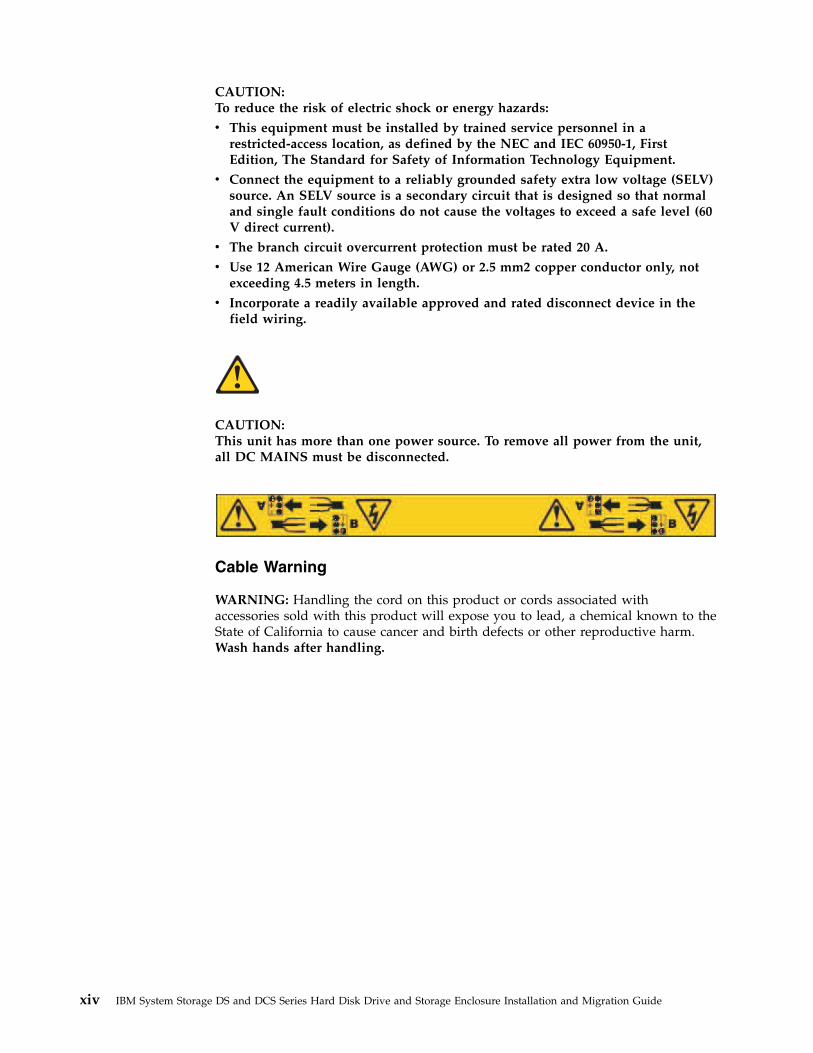
CAUTION:To reduce the risk of electric shock or energy hazards:
v This equipment must be installed by trained service personnel in arestricted-access location, as defined by the NEC and IEC 60950-1, FirstEdition, The Standard for Safety of Information Technology Equipment.
v Connect the equipment to a reliably grounded safety extra low voltage (SELV)source. An SELV source is a secondary circuit that is designed so that normaland single fault conditions do not cause the voltages to exceed a safe level (60V direct current).
v The branch circuit overcurrent protection must be rated 20 A.
v Use 12 American Wire Gauge (AWG) or 2.5 mm2 copper conductor only, notexceeding 4.5 meters in length.
v Incorporate a readily available approved and rated disconnect device in thefield wiring.
CAUTION:This unit has more than one power source. To remove all power from the unit,all DC MAINS must be disconnected.
Cable Warning
WARNING: Handling the cord on this product or cords associated withaccessories sold with this product will expose you to lead, a chemical known to theState of California to cause cancer and birth defects or other reproductive harm.Wash hands after handling.
xiv IBM System Storage DS and DCS Series Hard Disk Drive and Storage Enclosure Installation and Migration Guide
Chapter 1. Prerequisites to adding capacity and hard diskdrive migration
The following notes describe general information that you must consider whenyou perform the procedures in this document.v Check the controller firmware readme files, the documentation that comes with
your hardware, and this guide for the following information:– The latest information about storage subsystem and storage enclosure
compatibility– The latest information and rules about storage enclosure cabling to the
storage subsystem drive port– Any requirements of the installed microcode and firmware to support the
storage subsystem and storage enclosurev To prevent damage to the storage subsystem or to the storage enclosure
backplane, ensure that the hard disk drives are compatible with your storagesubsystem before you install them. Refer to the storage subsystemannouncement letter for information about compatible devices.
v For more information about the procedures in this document, contact your IBMmarketing representative or authorized reseller.
Preparing the storage subsystemTo prepare the target and source storage subsystems to add storage capacity ormigrate hard disk drives, complete the following steps. Unless it is specifiedotherwise, perform the following steps on the target subsystem for adding newhard disk drive capacity and on both the target and source storage subsystems formigrating hard disk drives with data.
Attention: Failure to complete the following steps before you add storagecapacity or migrate hard disk drives might result in loss of data availability or lossof data.1. Complete a full backup of all data on the storage subsystem.2. Ensure that the backup was successful.3. Verify the hardware compatibility and requirements by reviewing the
information in “Determining the supported number of drives and drive looppairs” on page 4 and the storage subsystem announcement letters. If additionof storage enclosures is required, review “Intermixing storage enclosures” onpage 21 and the cabling information in the Installation, User's, and MaintenanceGuide for any special cabling requirements.
4. If you want to perform a drive migration between storage subsystems, verifythat the drives can be migrated to the new storage subsystem.
Note: Currently, drives with disk pools cannot be migrated from onesubsystem to another. The data in the disk pool must be backed up to a tapeor to drives that are part of traditional arrays. Then, the data is restored tonewly created disk pools in another storage subsystem. For more information,see the “Drive migration limitations” on page 15 section.
5. Ensure that the storage subsystem has the latest controller firmware,nonvolatile storage random access memory (NVSRAM), and ESM firmware.Also, ensure that the installed controller firmware in the storage subsystem
© Copyright IBM Corp. 2008, 2013 1

supports the drives and storage enclosures. See “Verifying controller,NVSRAM, and ESM firmware compatibility” on page 9.
6. Ensure that the hard disk drive firmware is the latest level. Upgrading drivefirmware is a nonconcurrent operation. Schedule a maintenance windowduring which you can stop input and output to the storage subsystem fordrive firmware updates.
Note:
a. 3 Gbps SAS drives in a 6-Gbps SAS enclosure or 6-Gbps SAS drive in a3-Gbps SAS enclosure is not supported.
b. Do not move or migrate Fibre Channel drives from a 1-Gbps FibreChannel environment to a 2-Gbps Fibre Channel environment unless youinstall the latest firmware.
7. Verify that the storage subsystem is in Optimal state and does not stop in themiddle of long running tasks such as modifications to the dynamic logicaldrive expansion (DVE) or Array RAID levels. See the Recovery Guru functionin the Storage Subsystem Management window for instructions on bringingthe storage subsystem into Optimal state. Also, see “Bringing storagesubsystems and drive loops into optimal state” on page 21.
8. Resolve any critical errors reported in the Storage Subsystem MEL.9. Save and store the storage subsystem profile and configuration script along
with the collect all support data bundle.Attention: To prevent loss of data, do not store storage subsystem profiles orcollect all support data information in the same location as the logical drivesdefined on your storage subsystem.
10. Obtain and activate any required premium features.11. Ensure that the hard disk drives are compatible. See “Verifying hard disk
drive model compatibility” on page 17. Also, see the information for yourdrives in the announcement letter.
12. If you are adding capacity, see Chapter 2, “Adding or migrating hard diskdrives,” on page 57 or Chapter 3, “Adding or migrating storage enclosures,”on page 75, depending on the task you are performing.
13. (For the source storage subsystem only) Stop all programs, services, andprocesses in the host servers that access the logical drives defined in themigrated hard disk drives.
14. (For the source storage subsystem only) Ensure that no programs, services, orprocesses are running in the background that might write data to the logicaldrives. For example, Microsoft MSCS service periodically writes to theQuorum disk.
15. (For the source storage subsystem only) Unmount the file systems to flushI/O from the server cache to disk.
Note:
a. In a Microsoft Windows environment, remove the drive letter or themount points of the mapped LUNs instead of unmounting the filesystems.
b. See your operating-system documentation for detailed information aboutthe unmount procedure.
16. Back up the changes that you made during this procedure.17. If the migrated drives are FDE drives and were configured as part of secured
array, save the storage subsystem security (lock) key to unlock the drives afterinstalling them in a new storage subsystem. Without this key, the controllers
2 IBM System Storage DS and DCS Series Hard Disk Drive and Storage Enclosure Installation and Migration Guide

cannot unlock the drives to perform input and output processes. For detailsabout the security key, see the IBM System Storage DS Storage Manager Version10 Installation and Host Support Guide.If the migrated drives from the storage subsystem operate in external licensekey management mode, ensure that the new storage subsystem also operatesin external license key management mode and uses the same external keyserver.
18. See the applicable chapter to complete the task that you plan to perform.v Chapter 2, “Adding or migrating hard disk drives,” on page 57.v Chapter 3, “Adding or migrating storage enclosures,” on page 75.v Chapter 4, “Upgrading a storage subsystem controller,” on page 117.
Preparing to export and import drivesComplete the following steps on the source storage subsystem to prepare to exportdrives:1. Save the storage subsystem configuration so that a copy of the array
configuration is available, if the export fails.2. Stop all I/O and unmount or disconnect the file system.3. Back up the array data.4. Use the Locate Array function in the Storage Subsystem Manager window to
identify the physical disks that are associated with the array. Then, label eachdrive with source and target storage subsystem names, array name, and totalnumber of drives in the array. After the drives are exported or offline, youmight not be able to use the array locate function to locate the drives that arepart of an array, depending on the version of installed controller firmware.
5. Ensure that you have enough blank drive canisters or new drives to cover thedrive bays from which the drives are removed to maintain airflow in thestorage enclosure.
6. If the source storage subsystem contains secured full data encryption (FDE)arrays, save a copy of the security key in the target storage subsystem.
Verify the following on the target (destination) storage subsystem to prepare toexport drives:v You have enough drive bays for the drives.v The storage subsystem supports the drives. You cannot exceed the maximum
number of drives that the storage subsystem supports.v The storage subsystem supports the RAID level that you are importing. You
cannot exceed the maximum number of logical drives that the storage subsystemsupports.
v The target storage subsystem supports RAID level 6, if you are importing RAIDlevel 6.
v The controllers in the storage subsystem have the latest version of controllerfirmware.
v The latest DS Storage Manager software is installed.v You have purchased and enabled any premium feature keys.v If the source storage subsystem operates in external key management mode, the
target storage subsystem also operates in external key management mode and ismanaged by the same external key manager. That way, you do not have tosupply the security key to unlock the secured FDE drives when importing them.Otherwise, save the security key in the source storage subsystem.
Chapter 1. Prerequisites to adding capacity and hard disk drive migration 3

Determining the supported number of drives and drive loop pairsUse the information in this section to determine the hardware requirements beforeyou migrate storage subsystems or add hard disk drives. Table 1 provides a list ofthe supported number of drives and drive loop pairs for each storage subsystemby machine type and model number. It also specifies storage enclosure licenserequirements.
Note:
1. RAID 6 is supported only in storage subsystems with controller firmware07.xx.xx.xx.
2. RAID arrays in E-DDMs cannot be migrated to storage subsystems that useEV-DDMs, and vice versa.
3. Do not intermix Fibre Channel (FC) hard disk drives and Serial ATA (SATA)hard disk drives in the same storage subsystem environment unless youpurchase the Fibre Channel/SATA intermix premium feature entitlement andupgrade the storage subsystem controller firmware to the version that supportsthe intermix.
4. The Fibre Channel/SATA intermix premium feature entitlement might bestandard in some storage subsystem models. See the documentation that comeswith your storage subsystem for information. Also, see “DS4000 Fibre Channeland Serial ATA Intermix premium feature” on page 31.
Table 1. Supported drives and drive loop pairs in storage subsystems
Storage subsystemMachinetype
Modelnumber
Maximumdrives
Maximumdriveloop/channelpairs
Storageenclosurelicenserequirement
DS4100 (singlecontroller model)
17241SC, 1Sx
14 0 None. Storageenclosureattachment notsupported.
DS4100 1724 100 112 1 None
DS4200 Express1 18147VA, 7VH
112 1 Purchase 1–3and 4–6 storageenclosureattachmententitlements.
4 IBM System Storage DS and DCS Series Hard Disk Drive and Storage Enclosure Installation and Migration Guide

Table 1. Supported drives and drive loop pairs in storage subsystems (continued)
Storage subsystemMachinetype
Modelnumber
Maximumdrives
Maximumdriveloop/channelpairs
Storageenclosurelicenserequirement
DS4300 FibreChannel
1722 60X
60U
56 1 Purchasestorageenclosureentitlements inincrements upto three storageenclosures perDS4300 storagesubsystem.
DS4300 FibreChannel (with turbooption )3, 4
1122 1 None. Thestoragesubsystemincludes aseven storageenclosureentitlement.
DS4300 FibreChannel (singlecontroller model)
6LU
6LX
14 0 None. Storageenclosureattachment notsupported.
DS4400 FibreChannel
1742 1RU
1RX
224 2 None
DS4500 FibreChannel
1742 90X
90U
224 2 None
DS4700 ExpressFibre Channel1
1814 70A 70H70S 70T
112 1 Purchase 1–3and 4–6 storageenclosureattachmententitlements.
72A 72H72S 72T
112 1 Comes with 1–3storageenclosureattachmententitlements (64drives total).Must purchase4–6 storageenclosureattachments toget 112 drives.
Chapter 1. Prerequisites to adding capacity and hard disk drive migration 5
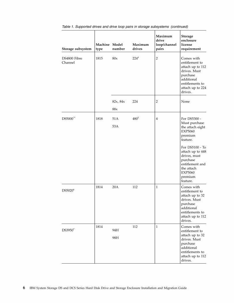
Table 1. Supported drives and drive loop pairs in storage subsystems (continued)
Storage subsystemMachinetype
Modelnumber
Maximumdrives
Maximumdriveloop/channelpairs
Storageenclosurelicenserequirement
DS4800 FibreChannel
1815 80x 2244 2 Comes withentitlement toattach up to 112drives. Mustpurchaseadditionalentitlements toattach up to 224drives.
82x, 84x
88x
224 2 None
DS5000™ 1818 51A
53A
4805 4 For DS5300 -Must purchasethe attach eightEXP5060premiumfeature.
For DS5100 - Toattach up to 448drives, mustpurchaseentitlement andthe attachEXP5060premiumfeature.
DS502061814 20A 112 1 Comes with
entitlement toattach up to 32drives. Mustpurchaseadditionalentitlements toattach up to 112drives.
DS395071814
94H
98H
112 1 Comes withentitlement toattach up to 32drives. Mustpurchaseadditionalentitlements toattach up to 112drives.
6 IBM System Storage DS and DCS Series Hard Disk Drive and Storage Enclosure Installation and Migration Guide
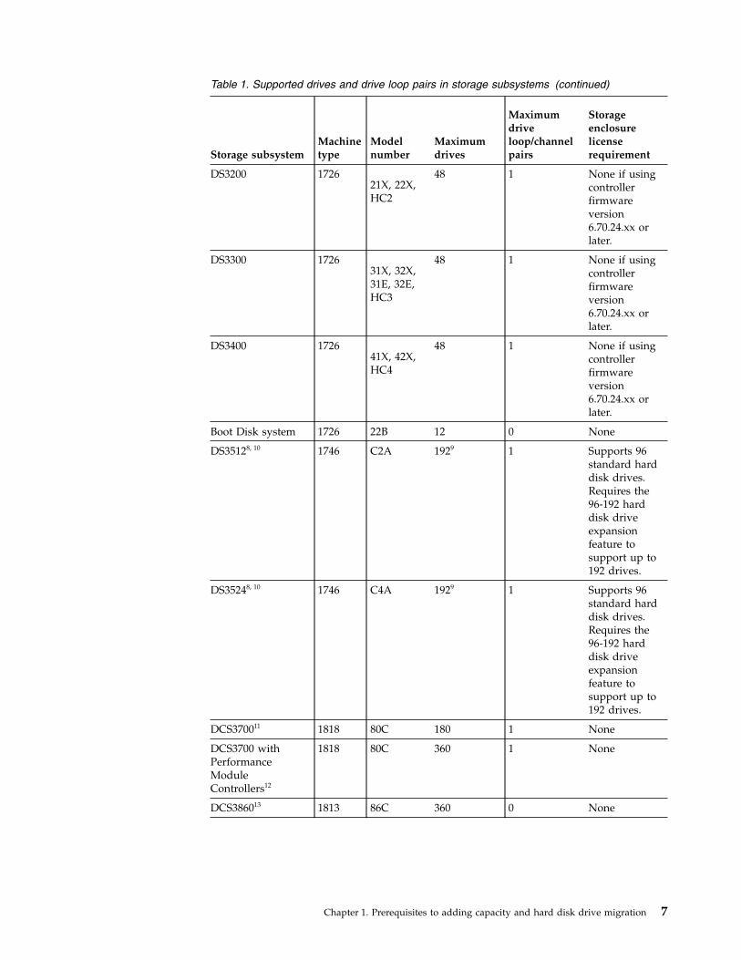
Table 1. Supported drives and drive loop pairs in storage subsystems (continued)
Storage subsystemMachinetype
Modelnumber
Maximumdrives
Maximumdriveloop/channelpairs
Storageenclosurelicenserequirement
DS3200 172621X, 22X,HC2
48 1 None if usingcontrollerfirmwareversion6.70.24.xx orlater.
DS3300 172631X, 32X,31E, 32E,HC3
48 1 None if usingcontrollerfirmwareversion6.70.24.xx orlater.
DS3400 172641X, 42X,HC4
48 1 None if usingcontrollerfirmwareversion6.70.24.xx orlater.
Boot Disk system 1726 22B 12 0 None
DS35128, 10 1746 C2A 1929 1 Supports 96standard harddisk drives.Requires the96-192 harddisk driveexpansionfeature tosupport up to192 drives.
DS35248, 10 1746 C4A 1929 1 Supports 96standard harddisk drives.Requires the96-192 harddisk driveexpansionfeature tosupport up to192 drives.
DCS370011 1818 80C 180 1 None
DCS3700 withPerformanceModuleControllers12
1818 80C 360 1 None
DCS386013 1813 86C 360 0 None
Chapter 1. Prerequisites to adding capacity and hard disk drive migration 7
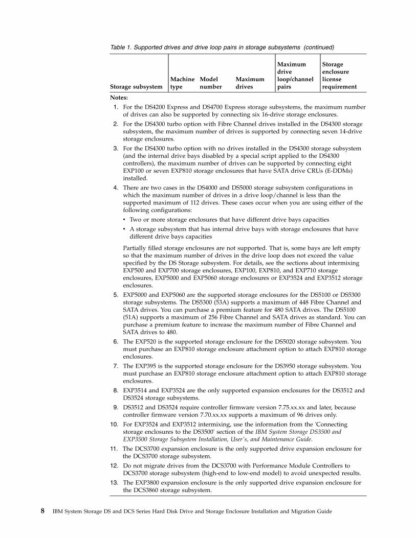
Table 1. Supported drives and drive loop pairs in storage subsystems (continued)
Storage subsystemMachinetype
Modelnumber
Maximumdrives
Maximumdriveloop/channelpairs
Storageenclosurelicenserequirement
Notes:
1. For the DS4200 Express and DS4700 Express storage subsystems, the maximum numberof drives can also be supported by connecting six 16-drive storage enclosures.
2. For the DS4300 turbo option with Fibre Channel drives installed in the DS4300 storagesubsystem, the maximum number of drives is supported by connecting seven 14-drivestorage enclosures.
3. For the DS4300 turbo option with no drives installed in the DS4300 storage subsystem(and the internal drive bays disabled by a special script applied to the DS4300controllers), the maximum number of drives can be supported by connecting eightEXP100 or seven EXP810 storage enclosures that have SATA drive CRUs (E-DDMs)installed.
4. There are two cases in the DS4000 and DS5000 storage subsystem configurations inwhich the maximum number of drives in a drive loop/channel is less than thesupported maximum of 112 drives. These cases occur when you are using either of thefollowing configurations:
v Two or more storage enclosures that have different drive bays capacities
v A storage subsystem that has internal drive bays with storage enclosures that havedifferent drive bays capacities
Partially filled storage enclosures are not supported. That is, some bays are left emptyso that the maximum number of drives in the drive loop does not exceed the valuespecified by the DS Storage subsystem. For details, see the sections about intermixingEXP500 and EXP700 storage enclosures, EXP100, EXP810, and EXP710 storageenclosures, EXP5000 and EXP5060 storage enclosures or EXP3524 and EXP3512 storageenclosures.
5. EXP5000 and EXP5060 are the supported storage enclosures for the DS5100 or DS5300storage subsystems. The DS5300 (53A) supports a maximum of 448 Fibre Channel andSATA drives. You can purchase a premium feature for 480 SATA drives. The DS5100(51A) supports a maximum of 256 Fibre Channel and SATA drives as standard. You canpurchase a premium feature to increase the maximum number of Fibre Channel andSATA drives to 480.
6. The EXP520 is the supported storage enclosure for the DS5020 storage subsystem. Youmust purchase an EXP810 storage enclosure attachment option to attach EXP810 storageenclosures.
7. The EXP395 is the supported storage enclosure for the DS3950 storage subsystem. Youmust purchase an EXP810 storage enclosure attachment option to attach EXP810 storageenclosures.
8. EXP3514 and EXP3524 are the only supported expansion enclosures for the DS3512 andDS3524 storage subsystems.
9. DS3512 and DS3524 require controller firmware version 7.75.xx.xx and later, becausecontroller firmware version 7.70.xx.xx supports a maximum of 96 drives only.
10. For EXP3524 and EXP3512 intermixing, use the information from the 'Connectingstorage enclosures to the DS3500' section of the IBM System Storage DS3500 andEXP3500 Storage Subsystem Installation, User's, and Maintenance Guide.
11. The DCS3700 expansion enclosure is the only supported drive expansion enclosure forthe DCS3700 storage subsystem.
12. Do not migrate drives from the DCS3700 with Performance Module Controllers toDCS3700 storage subsystem (high-end to low-end model) to avoid unexpected results.
13. The EXP3800 expansion enclosure is the only supported drive expansion enclosure forthe DCS3860 storage subsystem.
8 IBM System Storage DS and DCS Series Hard Disk Drive and Storage Enclosure Installation and Migration Guide

Verifying controller, NVSRAM, and ESM firmware compatibilityUse the information in this section to verify controller, NVSRAM, and ESMfirmware compatibility before you migrate storage subsystems or add hard diskdrives. For firmware compatibility between the migrating and original hardware,the controller firmware and NVSRAM of the target migration storage subsystemmust be at the levels that are indicated in Table 2.
You can use the DS Storage Manager Client software and the controller firmwareto upgrade the ESM firmware while the storage subsystem receives I/O from thehost server, if you select only one storage enclosure to download the ESMfirmware at a time in the Select Drive Enclosure To Download ESM FirmwareWindow.
Note:
1. See the most recent readme file that is included with the storage subsystemcontroller firmware package. To access the most recent readme file, see“Finding Storage Manager software, controller firmware, and readme files” onpage 147.
2. See the readme file for any I/O operation requirements. Some controllerfirmware upgrade scenarios might require that you first quiesce host I/Ooperations.
3. See the readme file to ensure that the firmware is compatible with thecontroller firmware in the storage subsystem that you are upgrading.
4. Although you can upgrade the storage subsystem and ESM firmware while itprocesses I/O from the host server, schedule upgrades to occur during timeperiods of low I/O between the storage subsystems and host servers.
Table 2 lists the supported machine types, model numbers, and the latest version ofreleased Storage Manager software and controller firmware levels for each machinetype. Review the announcement letter for your drives and the readme file of theESM and hard disk drive firmware package for any controller firmware and ESMfirmware requirements.
Note: If your product contains controller firmware earlier than 6.xx.xx.xx, use anearlier storage manager software. IBM DS Storage Manager version 10.77 hostsoftware requires that the DS3000 or DCS Series/DS4000/DS5000 storagesubsystem controller firmware is at version 06.xx.xx.xx or later. The IBM DS4000Storage Manager v9.60 supports storage subsystems with controller firmwareversion 04.xx.xx.xx up to 05.2x.xx.xx. The IBM DS Storage Manager v10.36supports storage subsystems with controller firmware version 5.3x.xx.xx to07.36.xx.xx. The IBM DS Storage Manager v10.70 supports storage subsystems withcontroller firmware version 05.4x.xx.xx to 07.70.xx.xx.
Table 2. Machine types, supported controller firmware, and supported Storage Managersoftware
Storage subsystem Machinetype
Model Supportedcontrollerfirmwarelevel12
Supported StorageManager softwareversion
IBM Boot Disk System 1726 22B 6.30.xx.xx 10.8x.xx.xx,11.2x.xx.xx
DS3200 1726 21X, 22X,HC2 7.35.xx.xx
10.8x.xx.xx,11.2x.xx.xx
Chapter 1. Prerequisites to adding capacity and hard disk drive migration 9

Table 2. Machine types, supported controller firmware, and supported Storage Managersoftware (continued)
Storage subsystem Machinetype
Model Supportedcontrollerfirmwarelevel12
Supported StorageManager softwareversion
DS3300 1726 31X, 32X,31E, 32E,HC3
7.35.xx.xx10.8x.xx.xx,11.2x.xx.xx
DS3400 1726 41X, 42X,HC4 7.35.xx.xx
10.8x.xx.xx,11.2x.xx.xx
DS3512 1746 C2A 7.7x.xx.xx,7.8x.xx.xx,8.2x.xx.xx
10.8x.xx.xx,11.2x.xx.xx
DS3524 1746 C4A,C2T
7.7x.xx.xx,7.8x.xx.xx,8.2x.xx.xx
10.8x.xx.xx,11.2x.xx.xx
DCS3700 1818 80C 7.77.xx.xx,7.8x.xx.xx,8.2x.xx.xx
10.8x.xx.xx,11.2x.xx.xx
DCS3700 with PerformanceModule Controllers
1818 80C 7.8x.xx.xx,8.2x.xx.xx
10.8x.xx.xx,11.2x.xx.xx
DCS3860 1813 86C 7.8x.xx.xx,8.2x.xx.xx
10.8x.xx.xx,11.2x.xx.xx
DS3950 1814 94H, 98H 7.7x.xx.xx,7.8x.xx.xx
10.8x.xx.xx,11.2x.xx.xx
DS4100 1724 1SC, 1SX,100
6.12.xx.xx 10.8x.xx.xx,11.2x.xx.xx
DS4200 1814 7VA/H 6.60.xx.xx,7.60.xx.xx
10.8x.xx.xx,11.2x.xx.xx
DS4300 (single controller) 1722 6LU, 6LX 5.34.xx.xx 10.7x.xx.xx,10.8x.xx.xx,11.2x.xx.xx
DS4300 (base model) 60U, 60X 6.60.xx.xx 10.7x.xx.xx,10.8x.xx.xx,11.2x.xx.xx
DS4300 (turbo model) 60U, 60X 5.41.xx.xx(supportsEXP100only), 6.60.xx
DS4400 1742 1RU,1RX
6.12.xx.xx 10.8x.xx.xx,11.2x.xx.xx
DS4500 1742 90X, 90U 5.41.xx.xx(supportsEXP100only), 6.60.xx
10.7x.xx.xx,10.8x.xx.xx,11.2x.xx.xx
DS4700 1814 70A/H,72A/H
6.60.xx.xx,7.60.xx.xx
10.8x.xx.xx,11.2x.xx.xx
DS4800 1815 80A/H 6.60.xx.xx,7.60.xx.xx
10.8x.xx.xx,11.2x.xx.xx
82A/H84A/H88A/H
6.60.xx.xx,7.60.xx.xx
10.8x.xx.xx,11.2x.xx.xx
10 IBM System Storage DS and DCS Series Hard Disk Drive and Storage Enclosure Installation and Migration Guide

Table 2. Machine types, supported controller firmware, and supported Storage Managersoftware (continued)
Storage subsystem Machinetype
Model Supportedcontrollerfirmwarelevel12
Supported StorageManager softwareversion
DS5020 1814 20A 7.7x.xx.xx,7.8x.xx.xx
10.8x.xx.xx,11.2x.xx.xx
DS5100 or DS5300 1818 51A, 53A 7.60.xx.xx,7.7x.xx.xxand7.8x.xx.xx
10.8x.xx.xx,11.2x.xx.xx
Important:
1. Controller firmware levels 06.23.xx.xx and 6.60.xx.xx support the DS4200,DS4300, DS4500, DS4700, and DS4800 storage subsystems. This firmwaresupports the intermixing of EXP100, EXP710, and EXP810 storage enclosuresbehind these models. It also supports the intermixing of Fibre Channel andSATA drives within the EXP810 storage enclosure.
2. Controller firmware level 06.19.xx.xx supports only the DS4300 (base andturbo models only) and DS4500 storage subsystems. This firmware levelsupports the intermixing of EXP810, EXP710, and EXP100 storage enclosuresbehind a DS4000® storage subsystem.
3. Controller firmware levels 06.15.xx.xx and 06.14.xx.xx support only the DS4800storage subsystem. Controller firmware level 06.15.xx.xx supports EXP100SATA drive storage enclosures with the DS4800 storage subsystem.
4. Controller firmware 06.16.xx.xx is required to support DS4000 storagesubsystems that have EXP810 storage enclosures attached. It does not supportEXP100 storage enclosures. Do not download 06.16.xx.xx into DS4000 storagesubsystems that have EXP100 storage enclosures attached. If controllerfirmware 06.16.xx.xx is activated, the storage subsystem does not recognizethe drives in EXP100 storage enclosures, causing loss of data availability to theRAID arrays and logical drives that are defined in those drives. Use controllerfirmware level 06.15.xx.xx if EXP100 storage enclosures are attached or if youplan to attach them in the future.
5. EXP710 storage enclosures are supported with controller firmware version06.1x.xx.xx, or later.
6. Controller firmware level 06.12.xx.xx or later supports EXP100 SATA drivestorage enclosures with the following storage subsystems:v DS4100 base modelsv DS4300 base modelsv DS4300 turbo modelsv DS4400v DS4500
7. Controller firmware version 7.60.xx.xx and later is required to support theEXP5060 expansion enclosure.
8. Some firmware levels support the intermixing of Fibre Channel and SATAdrive storage enclosures in the same DS4000 storage subsystem, if the DS4000Fibre Channel/SATA Intermix premium feature is enabled. For moreinformation, see the IBM System Storage DS4000 Fibre Channel and Serial ATAIntermix Premium Feature Installation Overview.
Chapter 1. Prerequisites to adding capacity and hard disk drive migration 11

9. DS4800 storage subsystem model 80A/H does not support controller firmwarelevel 6.16.14.xx and 6.16.15.xx.
10. For the latest NVSRAM versions, see http://www.ibm.com/systems/support/storage/disk/.
11. The DS4000 storage subsystem from the factory identifies the NVSRAMversion with an “M” prefix instead of an “N” prefix. Both NVSRAM versionsare the same, if the rest of the version information is the same. For example,the N1815D480R915V05 and M1815D480R915V05 versions are the samebecause both versions share “1815D480R915V05” string. TheM1815D480R915V05 version was installed at the factory. TheN1815D480R915V05 version is available on the web.
12. If the controller firmware of a storage subsystem from which drives aremigrated is not version 7.10.xx or later and the controller firmware of thetarget migration storage subsystem is 7.10.xx or later, only the basic logicaldrives are migrated. Copy Services logical drives such as FlashCopy®,VolumeCopy, and Enhanced Remote Mirroring are not migrated. Before youmigrate hard disk drives, complete the following steps:a. Back up the data in the FlashCopy logical drives and then delete the
FlashCopy logical drives and repository logical drives.b. Wait for VolumeCopy mirroring to be completed and then break the
VolumeCopy mirroring pairs.c. Remove the Enhanced Remote Mirroring relationships.
13.
To verify software version levels or to identify possible interim updates tofirmware and NVSRAM file versions that are described in Table 2 on page 9,go to http://www.ibm.com/systems/support/storage/disk/.Before you update the controller firmware and NVSRAM to the version that isindicated in Table 3, see the readme file included in the controller firmwarecode package for information about upgrades or stepping-stone controllerfirmware upgrades that you must perform first.Table 3 lists storage enclosure models by name, machine type, model number,and current ESM firmware level.
Table 3. Compatible storage enclosure ESM firmware level by machine type and modelnumber
Storage subsystem and storageenclosure product name/model
Machinetype
Modelnumber ESM firmware level
DS4000 EXP100 1710 10U9566 or later .
DS4000 EXP710 1740 710 9682 or later
DS4000 EXP420 1812 8VA, 8VH 98G0 or later
DS4000 EXP810 1812 81A, 81H,81S, 81T
98G0 or later
DS5000 EXP5000 1818 D1A 98G0 or later
DS5000 EXP520 1814 52A 98G0 or later
DS5000 EXP5060 1818 G1A 9921 or later
DS3950 EXP395 1814 92H 98G0 or later
DS3000 EXP3000 1727 1RX 019A or later
DS3500 EXP3512 1746 E2A 0363 or later
DS3500 EXP3524 1746 E4A 0363 or later
12 IBM System Storage DS and DCS Series Hard Disk Drive and Storage Enclosure Installation and Migration Guide

Table 3. Compatible storage enclosure ESM firmware level by machine type and modelnumber (continued)
Storage subsystem and storageenclosure product name/model
Machinetype
Modelnumber ESM firmware level
DCS3700 expansion enclosure 1818 80E 0363 or later
DCS3860 EXP3800 1813 80E 3.93 or later
Storage subsystem profileFor controllers with firmware level 6.1x.xx.xx or later, go to the Storage SubsystemManagement window and click Storage Subsystem > View Profile. For controllerswith firmware level 5.xx.xx.xx.xx or earlier, click View > Storage SubsystemProfile. In either circumstance, when the Storage Subsystem Profile window opens,click the All tab and scroll through the Profile For Storage Subsystem section tolocate the following information.
Note: The Profile For Storage Subsystem section contains all the profileinformation for the entire subsystem. Therefore, it might be necessary to scrollthrough a large amount of information to locate the firmware level numbers.
Storage Subsystem
v NVSRAM versionv Controller firmware (or appware, bootware, or both) version
See the following example of profile information.
Controller in Enclosure 0, Slot AStatus: OnlineCurrent configurationFirmware version: 06.10.07.00Appware version: 06.10.07.00Bootware version: 06.10.07.00NVSRAM version: 1722F600R910V05
Drives
v Firmware levelv ATA translator card (for EXP810 storage enclosure SATA drive only)
ESM
v ESM card firmware level
Physical View paneSelect a procedure to view the firmware level from the Physical View pane of theStorage Subsystem Management window.
To obtain the controller firmware level:Right-click the Controller icon in the Physical View pane of the StorageSubsystem Management window and select Properties. The ControllerEnclosure properties window opens, and the properties for that controllerare shown.
You must perform this step for each individual controller.
To obtain the drive and ATA translator firmware level:Right-click the Drive icon in the Physical View pane of the Storage
Chapter 1. Prerequisites to adding capacity and hard disk drive migration 13

Subsystem Management window and select Properties. The DriveProperties window opens, and the properties for that drive are shown.
You must perform this step for each individual drive.
To obtain the ESM firmware and drive enclosure component firmware levels:
1. In the Physical View pane of the Storage Subsystem Managementwindow, click the Drive Enclosure Component icon (the icon farthestto the right). The Drive Enclosure Component Information windowopens.
2. Click the ESM icon in the left pane. The ESM information is shown inthe right pane of the Drive Enclosure Component Information window.
3. Locate the firmware level of each ESM in the drive enclosure.You must perform this step for each storage enclosure.
Upgrading ESM and controller firmwareUse the information in this section to upgrade the ESM and controller firmware inthe source and target storage subsystems before you start the migration procedure.
To upgrade ESM and controller firmware, complete the following steps:1. Upgrade the DS Storage Manager software to the latest version. For more
information, see the applicable IBM System Storage DS Storage ManagerInstallation and Support Guide. To access the latest document, go tohttp://www.ibm.com/systems/support/storage/disk/.
Note: To maintain compatibility, update the multi-path software on the hostserver to the level that is supported by or released with the controller firmwarethat you intend to download. For details about software compatibility, seehttp://www.ibm.com/systems/support/storage/config/ssic/index.jsp.
2. Upgrade the storage enclosure ESM firmware. You can use DS Storage Managerand controller firmware to update the ESM firmware while the storagesubsystem is processing I/O from the host server if the ESM firmwaredownload is performed to only one storage enclosure at a time. If you selectmultiple entries in the ESM firmware download window for ESM firmwaredownload, you must quiesce I/O operations from the host servers before youstart the ESM firmware download process.
Note: Even though the storage subsystem supports controller and ESMfirmware upgrade while the storage subsystem processes I/O from the hostserver, schedule controller and ESM firmware upgrades to occur during timeperiods of low I/O between the storage subsystems and host servers.
3. Upgrade the controller firmware and NVSRAM. See Table 2 on page 9 and step1.
Note: See the readme file in the DS Storage Manager controller firmwarepackage that is associated with the applicable host operating systemenvironment for a support statement about the concurrent controller firmwaredownload (that is, downloading code to the DS4000 storage subsystem while itis processing I/O from the host server).
14 IBM System Storage DS and DCS Series Hard Disk Drive and Storage Enclosure Installation and Migration Guide
Attention: Before you upgrade the controller firmware, see the readme file thatcomes with the firmware for any special prerequisite tasks, ESM firmware, andstepping-stone controller firmware that must be installed before the controller canbe upgraded. Failure to do so might result in loss of data availability. There arecertain minimum controller firmware level requirements that are associated withvarious storage enclosures. See Table 7 on page 23, Table 9 on page 24, and Table 13on page 27 for related information.
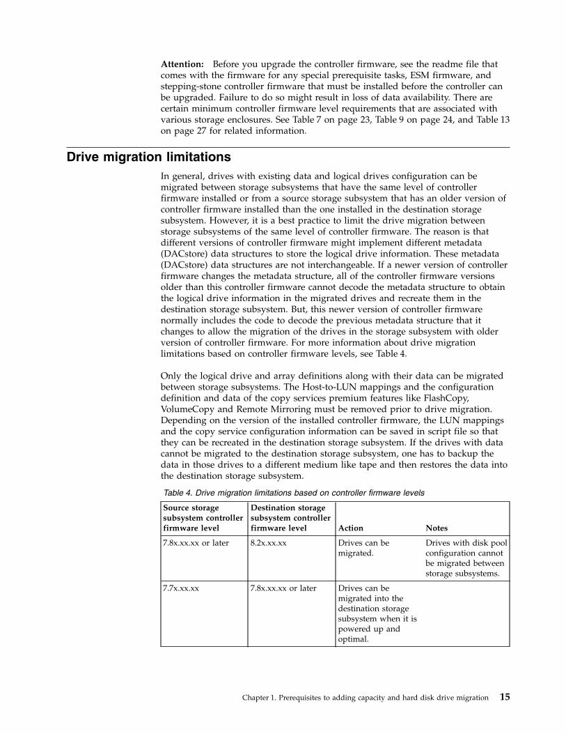
Drive migration limitationsIn general, drives with existing data and logical drives configuration can bemigrated between storage subsystems that have the same level of controllerfirmware installed or from a source storage subsystem that has an older version ofcontroller firmware installed than the one installed in the destination storagesubsystem. However, it is a best practice to limit the drive migration betweenstorage subsystems of the same level of controller firmware. The reason is thatdifferent versions of controller firmware might implement different metadata(DACstore) data structures to store the logical drive information. These metadata(DACstore) data structures are not interchangeable. If a newer version of controllerfirmware changes the metadata structure, all of the controller firmware versionsolder than this controller firmware cannot decode the metadata structure to obtainthe logical drive information in the migrated drives and recreate them in thedestination storage subsystem. But, this newer version of controller firmwarenormally includes the code to decode the previous metadata structure that itchanges to allow the migration of the drives in the storage subsystem with olderversion of controller firmware. For more information about drive migrationlimitations based on controller firmware levels, see Table 4.
Only the logical drive and array definitions along with their data can be migratedbetween storage subsystems. The Host-to-LUN mappings and the configurationdefinition and data of the copy services premium features like FlashCopy,VolumeCopy and Remote Mirroring must be removed prior to drive migration.Depending on the version of the installed controller firmware, the LUN mappingsand the copy service configuration information can be saved in script file so thatthey can be recreated in the destination storage subsystem. If the drives with datacannot be migrated to the destination storage subsystem, one has to backup thedata in those drives to a different medium like tape and then restores the data intothe destination storage subsystem.
Table 4. Drive migration limitations based on controller firmware levels
Source storagesubsystem controllerfirmware level
Destination storagesubsystem controllerfirmware level Action Notes
7.8x.xx.xx or later 8.2x.xx.xx Drives can bemigrated.
Drives with disk poolconfiguration cannotbe migrated betweenstorage subsystems.
7.7x.xx.xx 7.8x.xx.xx or later Drives can bemigrated into thedestination storagesubsystem when it ispowered up andoptimal.
Chapter 1. Prerequisites to adding capacity and hard disk drive migration 15

Table 4. Drive migration limitations based on controller firmware levels (continued)
Source storagesubsystem controllerfirmware level
Destination storagesubsystem controllerfirmware level Action Notes
7.8x.xx.xx or later 7.8x.xx.xx Drives can bemigrated.
1. Drives with diskpoolconfigurationcannot bemigrated betweenstoragesubsystems.
2. DS3500 andDCS3700 storagesubsystems withcontrollerfirmware version7.86 or latersupport T10PI. Ifan array has beenconfigured andT10PI enabled, itcannot bemigrated to astorage subsystemwith controllerfirmware version7.84 or earlier.
7.8x.xx.xx or later 7.7x.xx.xx or earlier Drives cannot bemigrated.
7.7x.xx.xx (DS3500,DCS3700 only)
7.7x.xx.xx (DS3500,DCS3700 only)
Drives can bemigrated
7.1x.xx.xx -7.6x.xx.xx,7.7x.xx.xx (DS5100,DS5300,DS5020&DS3950only)
7.1x.xx.xx -7.6x.xx.xx, 7.7x.xx.xx(DS5100, DS5300,DS5020&DS3950only)
Drives can bemigrated
6.xx.xx.xx or5.xx.xx.xx
6.xx.xx.xx or5.xx.xx.xx
Drives can bemigrated
6.xx.xx.xx or5.xx.xx.xx
7.8x.xx.xx, 7.7x.xx.xx,7.1x.xx.xx - 7.6x.xx.xx
Drives can bemigrated into thedestination storagesubsystem when it ispowered up and inoptimal state.
See notes 1 and 2.
7.1x.xx.xx -7.6x.xx.xx 7.8x.xx.xx, 7.7x.xx.xx Drives can bemigrated into thedestination storagesubsystem when it ispowered up and inoptimal state.
7.7x.xx.xx (DS3500,DCS3700 andDCS3860 only)
7.1x.xx.xx -7.6x.xx.xx, 6.xx.xx.xx
Not supported The minimumcontroller firmwareversion for DS3500 is7.70.xx.xx and forDCS3700 is7.77.xx.xx.
16 IBM System Storage DS and DCS Series Hard Disk Drive and Storage Enclosure Installation and Migration Guide

Table 4. Drive migration limitations based on controller firmware levels (continued)
Source storagesubsystem controllerfirmware level
Destination storagesubsystem controllerfirmware level Action Notes
7.7x.xx.xx (DS5100,DS5300, DS5020,DS3950 only)
7.1x.xx.xx - 7.6x.xx.xx Drives can bemigrated
7.7x.xx.xx (DS5100,DS5300, DS5020,DS3950 only)
6.xx.xx.xx Supported only whenthe destinationstorage subsystem isupgraded tocontroller firmwareversion 7.6x.xx.xx or7.7x.xx.xx first. If thatis not possible, thedrive migration isnot supported.
7.1x.xx.xx - 7.6x.xx.xx 6.xx.xx.xx Supported only whenthe destinationstorage subsystem isupgraded to thesame controllerfirmware version asin the source storagesubsystem first. Ifthat is not possible,the drive migration isnot supported
Note:
1. If a RAID array was created by a DS4000 storage subsystem that uses controllerfirmware level 05.30.xx.xx or earlier, it must be migrated to a storage subsystemwith controller firmware level 6.xx.xx.xx first before it can be migrated to astorage subsystem with controller firmware level 7.xx.xx.xx.
2. If a RAID array was created by a DS4000 storage subsystem that uses controllerfirmware level 05.4x.xx.xx, either upgrade the controller firmware to asupported 6.xx.xx.xx version or migrate it to a storage subsystem withcontroller firmware level 6.xx.xx.xx first before you migrate it to a storagesubsystem with controller firmware level 7.xx.xx.xx.
Verifying hard disk drive model compatibilityUse the information in this section to verify hard disk drive compatibility beforeyou start the migration procedure or to add hard disk drives.v Do not use the drive product identifier as the only source to determine drive
compatibility for a subsystem. Drives that have the same product identifiermight require a different mounting tray or interposer in a storage subsystem.Instead, use the drive option part number or drive CRU part number to checkfor drive compatibility in a storage subsystem.
v Ensure that the drives can operate at the interface speed of the driveloop/channel. If not, the drives are in Bypassed mode or are not identified bythe controllers. In a few instances, inserting a drive with the wrong driveinterface speed causes problems in the drive loops which could result in loss ofdata access.
Chapter 1. Prerequisites to adding capacity and hard disk drive migration 17
v Some storage subsystem and expansion enclosures can support different driveinterface speeds. Ensure that these storage subsystem and expansion enclosurespeed switches are set to the correct values to support the drive interface speeds.Intermixing storage subsystems and expansion enclosures that support differentdrive interface speeds is not supported. The drive loop/channel must be set tosupport the lowest drive interface speed.
v The Fibre Channel drive CRU for the EXP710 storage enclosure is not compatiblewith the Fibre Channel drive CRU for the EXP810 storage enclosure, althoughthe product ID is the same for both EXP710 and EXP810 storage enclosure driveCRUs. See the documentation that comes with the storage enclosures and thedocumentation that comes with the hard disk drive options.
v Do not use SATA and Fibre Channel drives or enclosures together in the samedrive loop behind a DS4000 storage subsystem unless you obtain the FibreChannel/SATA intermix premium feature and the storage subsystem supportsthe Fibre Channel/SATA intermix feature.
v Do not install SATA hard disk drives in storage enclosures that support onlyFibre Channel hard disk drives. Do not install Fibre Channel hard disk drives instorage enclosures that support only SATA hard disk drives. The DS3950,DS4700, and DS5020 storage subsystems with an EXP3950, EXP520, EXP810, orEXP5000 expansion enclosures attached are the only models that support bothFibre Channel and SATA hard disk drives.
v Do not install a DS3000 or DCS Series storage subsystem drive in a DS4000 orDS5000 storage subsystem.
v Do not install a DS4000 or DS5000 storage subsystem drive in a DS3000 or DCSSeries storage subsystem.
v Solid-state drives require controller firmware version 7.60.xx.xx and higher forthe DS5100 and DS5300 storage subsystems, controller firmware version7.70.xx.xx for the DS5020 storage subsystem, and controller firmware version7.77.xx.xx for the DS3500 storage subsystem.
v Full data encryption (FDE) drives require controller firmware 7.50.xx.xx andhigher for the DS5100 and DS5300 storage subsystems and controller firmwareversion 7.60.xx.xx and higher for the DS5020 and DS3950 storage subsystems.DS3500 storage subsystems require controller firmware 7.70.xx.xx and higher.
v SAS interface drives with SAS-FC interposer card (FC-SAS drives) requirecontroller firmware 7.77.xx.xx and higher.
v T10PI capable drives require controller firmware version 10.77.xx.xx and later.v The only DS4000 storage subsystem attached storage enclosure that supports the
4-Gbps hard disk drive and the 2-Gbps drive is the EXP810 storage enclosure;however, it can support only one drive speed in a single drive channel/looppair. The 2-Gbps drives either are in Bypassed mode or are not identified by thecontrollers when they are inserted in an EXP810 storage enclosure that isoperating at 4-Gbps Fibre Channel speed.
v The EXP395, EXP520, and EXP5000 storage enclosures support 4-Gbps drivesonly.
v The EXP520 storage enclosure is designed for the DS5020 (1814-20A) storagesubsystem. You can connect them at no additional charge. However, if you wantto attach the EXP810 storage enclosure to the DS5020 storage subsystem, youmust purchase the Attach EXP810 storage enclosure to DS5020 Activation option.
v The EXP395 storage enclosure is designed for the DS3950 storage subsystem.You can connect them at no additional charge. However, if you want to attachthe EXP810 storage enclosure to the DS3950 storage subsystem, you mustpurchase the Attach EXP810 storage enclosure to DS3950 Activation option.
18 IBM System Storage DS and DCS Series Hard Disk Drive and Storage Enclosure Installation and Migration Guide

v For information about the EXP5000 and EXP5060 storage enclosures, see Note 2on page 24.
v The 3 TB and higher capacity EXP5060 SATA drives require the ATA translatorfirmware in the EXP5060 drive slot to be at version LW1613 or higher. Refer tothe flyer that is shipped with your drive option of the EXP5060 IUMG for moreinformation.
v The EXP3512 and EXP3524 storage enclosures are supported with DS3500storage subsystems only.
v The EXP3000 storage enclosure is supported with DS3000 storage subsystemsonly.
v The DCS3700 storage expansion enclosure is supported with the DCS3700storage subsystem and the DCS3700 storage subsystem with PerformanceModule Controllers only.
v The EXP3800 storage expansion enclosure is supported with the DCS3860storage subsystem only.
v For information about supported drive capacity and interface and drive speeds,contact your IBM marketing representative or authorized reseller, go tohttp://www.ibm.com/systems/support/storage/disk/, or see the latest StorageSubsystem announcement.
Note:
1. In general, Fibre Channel drives can operate at lower Fibre Channeloperating speeds than the speed for which the drive is rated. For example,2-Gbps Fibre Channel drives also operate at 1-Gbps speed; 4-Gbps FibreChannel drives also operate at 2-Gbps speed. Check the documentation ofthe storage subsystem or storage enclosure to determine whether a FibreChannel drive can operate at a lower speed. The drive might not be certifiedor might not have the correct form factor for that storage subsystem orstorage enclosure.
2. Intermixing 3-Gbps SAS drive storage enclosures (EXP3000 storage enclosure)or 3-Gbps SAS hard disk drives with 6-Gbps SAS drive storage enclosures(EXP3512 and EXP3524 storage enclosure) or 6-Gbps SAS hard disk drives isnot supported.
Viewing the product ID and model of a hard disk driveUse the information in this section to view the product ID and model of a harddisk drive by using the storage server profile before you start the migrationprocedure or to add hard disk drives. Use the product ID or model to determinewhether the drive is a 1 Gbps or 2-Gbps Fibre Channel drive. You can determinethe product ID and model of a hard disk drive from the storage server profilethrough the menu option in the Subsystem Management window. To get theprofile, in the Subsystem Management window, click View -> Storage SubsystemProfile (if the controller firmware level is 05.xx.xx, or earlier) or StorageSubsystem -> View Profile (if the controller firmware level is 06.xx.xx, or later).When the Storage Subsystem Profile window is shown, click the Drives tab andscroll down to view the product ID and model of a hard disk drive.
See Table 5 on page 20 for a sample profile that indicates the product ID of thedrive in bay 12 of enclosure ID 1 as ST3146756FC F. The Speed and Current DataRate fields show that this drive is a 15 krpm drive and is operating at 4-GbpsFibre Channel date rate. In addition, the drive is security capable and in a securestate that allows input and output processing to the drive from the controller.
Chapter 1. Prerequisites to adding capacity and hard disk drive migration 19
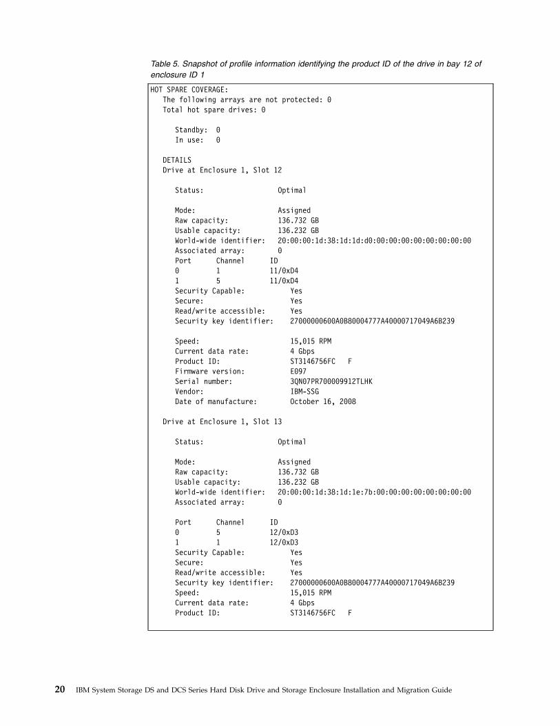
Table 5. Snapshot of profile information identifying the product ID of the drive in bay 12 ofenclosure ID 1
HOT SPARE COVERAGE:The following arrays are not protected: 0Total hot spare drives: 0
Standby: 0In use: 0
DETAILSDrive at Enclosure 1, Slot 12
Status: Optimal
Mode: AssignedRaw capacity: 136.732 GBUsable capacity: 136.232 GBWorld-wide identifier: 20:00:00:1d:38:1d:1d:d0:00:00:00:00:00:00:00:00Associated array: 0Port Channel ID0 1 11/0xD41 5 11/0xD4Security Capable: YesSecure: YesRead/write accessible: YesSecurity key identifier: 27000000600A0B80004777A40000717049A6B239
Speed: 15,015 RPMCurrent data rate: 4 GbpsProduct ID: ST3146756FC FFirmware version: E097Serial number: 3QN07PR700009912TLHKVendor: IBM-SSGDate of manufacture: October 16, 2008
Drive at Enclosure 1, Slot 13
Status: Optimal
Mode: AssignedRaw capacity: 136.732 GBUsable capacity: 136.232 GBWorld-wide identifier: 20:00:00:1d:38:1d:1e:7b:00:00:00:00:00:00:00:00Associated array: 0
Port Channel ID0 5 12/0xD31 1 12/0xD3Security Capable: YesSecure: YesRead/write accessible: YesSecurity key identifier: 27000000600A0B80004777A40000717049A6B239Speed: 15,015 RPMCurrent data rate: 4 GbpsProduct ID: ST3146756FC F
20 IBM System Storage DS and DCS Series Hard Disk Drive and Storage Enclosure Installation and Migration Guide

Bringing storage subsystems and drive loops into optimal stateYou can add or migrate storage enclosures only while the storage subsystem isturned on and in optimal state. To bring storage subsystems and drive loops intooptimal state, complete the following steps:1. Bring the storage subsystem to Optimal state before you reconfigure it with
new hardware.2. Use the DS Storage Manager Client program to display the status of the storage
subsystem and to correct any problems that might cause the storage subsystemto enter Needs Attention state.
3. Verify that all indicator lights on the storage subsystem are in Optimal state.4. Use the Read_Link_Status function of the DS Storage Manager Client program
and the storage subsystem MEL to verify that all components in the drive loopare in Optimal state. (Optimal state indicates that there are no drive loopcomponent errors in the event log and no errors in the Read_Link_Statuswindow.) If you are using controller firmware 06.10.xx.xx or later, use the drivechannel diagnostics to determine whether the drive loop/channel is in Optimalstate. For more information about the RLS and drive channel diagnostics if theyare supported by the installed version of your controller firmware, see theSubsystem Management window online help of the DS Storage Manager Clientprogram.Drive channel diagnostics are available only if you are using controllerfirmware level 06.10.xx.xx or later.
5. If the arrays are in degraded state because of a failed drive, correct the problembefore migration.
Note:
1. If necessary, contact IBM support for assistance with event log interpretation.2. For more information about verifying the Optimal state in storage subsystems
and drive loops, see the Problem Determination Guide for your storagesubsystem.
Before you add drives or storage enclosures, verify that the storage subsystem isnot performing any of the following tasks:v Dynamic logical drive capacity expansion
– Dynamic logical drive expansion (DVE)– Dynamic capacity expansion (DCE)
v Logical drive segment size modificationv Array RAID-level modificationv User-initiated array redundancy checking (click Array > Check Redundancy in
the Storage Subsystem Management window)v Remote mirror logical drive synchronizationv FlashCopy or VolumeCopy logical drive creationv Logical drive reconstruction or copyback (logical drive sparing)
Intermixing storage enclosuresThis section describes general information about intermixing storage enclosures ina storage subsystem. Use the information in this section to plan a storagesubsystem migration or to add hard disk drives. Special considerations aboutintermixing EXP810 and EXP5000 storage enclosures are presented in “Intermixing
Chapter 1. Prerequisites to adding capacity and hard disk drive migration 21

EXP810 and EXP5000 storage enclosures” on page 43. For information aboutintermixing EXP520 and EXP810 storage enclosures, see “Intermixing EXP520 andEXP810 storage enclosures” on page 37.
Note: For more information about intermixing legacy storage enclosures such asEXP100, EXP500, EXP700, and EXP710, see “Intermixing storage enclosures forDS4000 and DS5000 storage subsystems” on page 44.
For DS4000 storage subsystems, see “DS4000 Fibre Channel and Serial ATAIntermix premium feature” on page 31 for important information about using theFibre Channel and SATA Intermix premium feature, including configuration andsetup requirements. DS5000 storage subsystems come with the Fibre Channel andSATA Intermix premium feature as standard.
For hardware compatibility, ensure that the environmental service module (ESM)firmware for each storage enclosure and the storage server controller firmware is ator above the levels in Table 2 on page 9 and Table 3 on page 12.
Storage subsystems support the addition of external drive enclosures, which canprovide additional storage capacity (as in the case of DS4400, DS4500, DS4800,DS5100, and DS5300 storage subsystems) and capacity expansion beyond thestorage capacity of a DS4000 storage subsystem (in DS4100, DS4200 Express,DS4300, DS4700 Express, and DS5020 storage subsystems).
As of the date of this document, IBM supports EXP100, EXP420, EXP500, EXP520,EXP700, EXP710, EXP810, EXP5000, EXP395, and EXP5060 storage enclosures forDS4000 and DS5000 storage subsystems. For the DS3000 storage subsystems, IBMsupports the EXP3000 storage enclosure. For the DS3500 storage subsystem, IBMsupports the EXP3512 and EXP3524 storage enclosures. For the DCS3700 storagesubsystem and the DCS3700 storage subsystem with Performance ModuleControllers, IBM supports the DCS3700 storage expansion enclosure. For theDCS3860 storage subsystem, IBM supports the EXP3800 storage expansionenclosure.
When you increase the capacity of your storage subsystem in either of these ways,you might choose to add external drive enclosures of the same model and type orof different types. IBM does not support the combination of every external driveenclosure type and model in every storage subsystem configuration. In addition,not all controller firmware levels support all available storage enclosures or storagesubsystems.
In general, if a storage subsystem supports multiple storage enclosures withdifferent model numbers and machine types, you can connect the storageenclosures to the storage subsystem on the same redundant drive loop/channel byusing the cabling rules that are described in the storage subsystem documentation.As a best practice, group the storage enclosures by model and machine type whenyou connect cables in the same redundant drive loop/channels. However, becauseof storage enclosure architecture differences, there might be certain restrictionswhen you connect some combinations of storage enclosures in the same driveloop/channel. The restrictions are documented in this section and in “Intermixingstorage enclosures for DS4000 and DS5000 storage subsystems” on page 44.However, always review the latest version of your storage subsystem Installation,User's, and Maintenance Guide for the most up-to-date storage enclosure cablingrestrictions.
22 IBM System Storage DS and DCS Series Hard Disk Drive and Storage Enclosure Installation and Migration Guide

Table 6 indicates which storage enclosures can coexist in the same redundant driveloop, by model for the DS3000 storage subsystems. Table 7 indicates which storageenclosures can coexist in the same redundant drive loop, by model for the DS4000storage subsystems. Table 8 indicates which storage enclosures can coexist in thesame redundant drive loop, by model for the DS5000 storage subsystems.
Table 6. Mixed storage enclosure compatibility for DS3000 storage subsystem models.
Storage enclosure EXP3000 EXP3512 EXP3524
EXP3512 U U
EXP3524 U U
EXP3000 U
Table 7. Mixed storage enclosure compatibility for DS4000 storage subsystem models.
Storage subsystem andattached storage enclosure
DS4000 EXP100(SATA) DS4000 EXP420
DS4000 EXP710(Fibre Channel)
DS4000 EXP810(Fibre Channel /SATA)
DS4000 EXP100 (SATA) U1 U2U4
DS4000 EXP420 (SATA) U5
DS4000 EXP710 (FibreChannel)
U2 U4 U3
DS4000 EXP810 (FibreChannel / SATA) U4
U3 U 3
Notes:
1. Requires controller firmware 06.10.11.xx or later (DS4300 with turbo option, DS4400, and DS4500 storagesubsystems), 06.12.03.xx or later (DS4300 dual controller standard/base, DS4100 base storage subsystems),06.15.xx.xx (DS4800 storage subsystem), or 06.23.xx.xx or later (DS4700 and DS4800 storage subsystems).Controller firmware 06.16.xx.xx does not support the EXP100 storage enclosure.
There are versions of 05.41.xx.xx controller firmware that also provide EXP100 storage enclosure support forDS4300 (with dual controller standard/base or turbo option), DS4400, and DS4500 storage subsystems orversions of 05.42.xx.xx xx controller firmware that also provide EXP100 storage enclosure support for DS4100storage subsystems. Instead, use controller firmware level 06.12.xx.xx or later for DS4100, DS4300 (with base orturbo option), DS4400, and DS4500 storage subsystems.
2. Supported only with Fibre Channel/SATA intermix entitlement purchase and controller firmware level06.12.xx.xx or later. In addition, the storage subsystem must also support the Fibre Channel/SATA intermixpremium feature.
3. Requires controller firmware 06.16.xx.xx or later for DS4800 and DS4700 Express storage subsystems. TheEXP810 storage enclosure supports SATA drives with controller firmware level 06.16.8x.xx or later.
4. Requires controller firmware level 06.19.xx.xx or later with DS4300 and DS4500 storage subsystems, and version06.23.xx.xx or later with DS4700 and DS4800 storage subsystems.
You must purchase the Fibre Channel/SATA Intermix premium feature when to intermix EXP100 storageenclosures with EXP810 storage enclosures that have Fibre Channel drive CRUs (E-DDMs) installed.)
5. The EXP420 storage enclosure is supported for attachment to the DS4200 storage subsystem only. Requirescontroller firmware 06.16.8x.xx or later.
Table 8. Mixed storage enclosure compatibility for DS5000 storage subsystem models.
Storage subsystemand storage enclosure
EXP395 (FibreChannel / SATA)
DS5000 EXP5000(Fibre Channel /SATA)
DS5000 EXP520(Fibre Channel /SATA)
DS5000 EXP5060(SATA)
DS4000 EXP810(Fibre Channel /SATA)
DS4000 EXP810 (FibreChannel / SATA) U5 U1, 2 U3 U2, 4 U
Chapter 1. Prerequisites to adding capacity and hard disk drive migration 23

Table 8. Mixed storage enclosure compatibility for DS5000 storage subsystem models. (continued)
Storage subsystemand storage enclosure
EXP395 (FibreChannel / SATA)
DS5000 EXP5000(Fibre Channel /SATA)
DS5000 EXP520(Fibre Channel /SATA)
DS5000 EXP5060(SATA)
DS4000 EXP810(Fibre Channel /SATA)
DS5000 EXP5000 (FibreChannel / SATA)
U1 U U1, 2
DS5000 EXP520 (FibreChannel / SATA U U3
EXP395 (SATA)U U5
DS5000 EXP5060(SATA)4 U U U2
Notes:
1. Requires controller firmware 07.30.xx.xx or later.
2. The EXP5000 (1818-D1A) and EXP5060 storage enclosures are designed specifically for the DS5100 and DS5300(1818-51A and 1818-53A) storage subsystems and are the only supported storage enclosures, with the exceptionnoted in the following paragraph. This is a critical requirement because only the EXP5000 storage enclosure issupported with future enhancements of the DS5100 and DS5300 storage subsystems and only the EXP5000storage enclosure provides consistent warranty and support terms and conditions (including support servicesrepresentative installation and support for the entire system, and code upgrades within the initial warrantyperiod).
The only exception is that for client investment protection, existing EXP810 storage enclosures can be migratedfrom currently installed DS4700 or DS4800 storage subsystems to attach to a DS5100 or DS5300 storagesubsystem. A request for price quote (RPQ) approval is required for support of all migration configurations.With approved migration of EXP810 storage enclosures to a DS5100 or DS5300 storage subsystem, specialconsideration must be given to proper firmware levels and careful coordination of differences in warranty andmaintenance terms. You can submit an RPQ request through the normal process.
Purchase of new EXP810 storage enclosures to attach to DS5100 or DS5300 storage subsystem is not supportedor configurable in eConfig.
Disk drive modules that can be ordered in bulk or individually as customer installable parts for the EXP810storage enclosure are not supported for use in the EXP5000 storage enclosure. Only disk drive modules that areordered as feature codes of 1818–D1A and delivered preinstalled in the EXP5000 storage enclosure or asupgrades (installed only by a support services representative) are supported.
3. Controller firmware version 7.6x.xx.xx or later is required. Attachment of the EXP810 storage enclosure to theDS5020 storage subsystem requires the purchase of the Attach EXP810 storage enclosure to DS5020 Activationoption.
4. Controller firmware version 7.6x.xx.xx or later is required.
5. Controller firmware version 7.6x.xx.xx or later is required. Attachment of the EXP810 storage enclosure to theDS3950 storage subsystem requires purchase of the Attach EXP810 storage enclosure to DS3950 Activationoption.
Table 9 indicates which storage enclosures can attach to DS4000 storagesubsystems. Table 10 on page 26 indicates which storage enclosures can attach toDS5000 storage subsystems. Table 11 on page 27 indicates which storage enclosurescan attach to DS3000 storage subsystems.
Table 9. DS4000 storage subsystems storage enclosure compatibility
Storagesubsystem
DS4000 EXP100(SATA)
DS4000 EXP420(SATA)
DS4000 EXP710(Fibre Channel)
DS4000 EXP810 (Fibre Channel andSATA)
DS4100 (SATA) U
DS4200 (SATA) U
24 IBM System Storage DS and DCS Series Hard Disk Drive and Storage Enclosure Installation and Migration Guide

Table 9. DS4000 storage subsystems storage enclosure compatibility (continued)
Storagesubsystem
DS4000 EXP100(SATA)
DS4000 EXP420(SATA)
DS4000 EXP710(Fibre Channel)
DS4000 EXP810 (Fibre Channel andSATA)
DS4300 (turbooption, FibreChannel)
U
235
U4U5
DS4300 (basemodel, FibreChannel)
U
125
U4U5
DS4500 (FibreChannel, SATA) U
235
U4U5
DS4700 Express(Fibre Channel) U
235
U4 U
DS4800 (FibreChannel, SATA) U
235
U4 U
Chapter 1. Prerequisites to adding capacity and hard disk drive migration 25

Table 9. DS4000 storage subsystems storage enclosure compatibility (continued)
Storagesubsystem
DS4000 EXP100(SATA)
DS4000 EXP420(SATA)
DS4000 EXP710(Fibre Channel)
DS4000 EXP810 (Fibre Channel andSATA)
Notes:
1. The DS4300 storage subsystem base supports Fibre Channel/SATA intermixing only when the controllerfirmware is at version 06.12.xx.xx or later and the Fibre Channel/SATA intermix entitlement is purchased.
In addition, although the DS4300 storage subsystem (base model) supports Fibre Channel or SATA drives withcontroller firmware level 05.41.xx.xx, it does not support both in a mixed environment. However, it does supportSATA drives in an attached storage enclosure (only) but never in the storage subsystem itself. Also, see note 5.
2. DS4000 storage subsystems require the following firmware to manage EXP100 storage enclosures:
DS4300 base or turbo and DS4500Either 05.41.5x.xx or 06.1x.xx.xx or later. If possible, use level 06.60.xx.xx or later.
DS4700 Express06.23.xx.xx or later.
DS4800Use either 06.15.xx.xx, or 06.23.xx.xx or later. If possible, use level 6.60.xx.xx or later. 6.16.xx.xx does notsupport the EXP100 storage enclosure.
3. Requires controller firmware level 06.1x.xx.xx or later. Use level 06.60.xx.xx for DS4300 dual controllerstandard/base or turbo and DS4500 storage subsystems (also see note 5). For DS4700 Express and DS4800storage subsystems, use level 06.60.xx.xx (also see footnotes 4 and 5).
4. Requires controller firmware 06.16.18.xx or later for DS4800 and 06.16.4x.xx or later for DS4700 Express storagesubsystems. Also, see footnote 5 for the controller firmware requirement for intermixing EXP810 storageenclosures and EXP100 storage enclosures.
5. With DS4300 and DS4500 storage subsystems, controller firmware level 06.19.xx.xx or later is required tointermix EXP100 storage enclosures and EXP810 storage enclosures. With DS4700 Express and DS4800 storagesubsystems, version 06.23.xx.xx or later is required to intermix EXP100 storage enclosures and EXP810 storageenclosures.
6. Attachment of the EXP810 storage enclosure to the DS5020 storage subsystem requires the purchase of theAttach EXP810 storage enclosure to DS5020 Activation option.
7. Requires controller firmware 07.60.xx.xx or later.
Table 10. DS3950 and DS5000 storage subsystems storage enclosure compatibility
Storage subsystem
DS3950 EXP395(Fibre Channeland SATA)
DS5000 EXP5000(Fibre Channeland SATA)
DS5000 EXP520(Fibre Channeland SATA)
DS5000 EXP5060(SATA)
DS5000 EXP810(Fibre Channeland SATA)
DS3950U U4
DS5020 (FibreChannel, SATA) U U3
DS5100/ DS5300(Fibre Channel,SATA)
U U1 U2
Notes:
1. Attachment of the EXP810 storage enclosure to the DS5020 storage subsystemrequires the purchase of the Attach EXP810 storage enclosure to DS5020Activation option.
2. Requires controller firmware 07.30.xx.xx or later.3. For information about the EXP5000 and EXP5060 storage enclosures, see note 2
on page 24.
26 IBM System Storage DS and DCS Series Hard Disk Drive and Storage Enclosure Installation and Migration Guide

4. Controller firmware version 7.6x.xx.xx or later is required. Attachment of theEXP810 storage enclosure to the DS3950 storage subsystem requires thepurchase of the Attach EXP810 storage enclosure to DS3950 Activation option.
Table 11. Storage enclosure compatibility with storage subsystems by model for DS3000 storage subsystems
Storage subsystem EXP3000 EXP3512 EXP3524
DS3200
DS3300
DS3400
U
DS3512 U1 U1
DS3524 U1 U1
Note: Requires controller firmware version 7.70.xx.xx or later. Intermixing EXP3000 expansion enclosures andEXP3512/EXP3524 storage subsystems is not supported.
Table 12. Storage enclosure compatibility with storage subsystems by model for DCS Series storage subsystems
Storage subsystem DCS3700 Expansion Enclosure EXP3800
DCS3700U
DCS3700 with Performance ModuleControllers
U
DCS3860 U
Table 13. DS4000, and DS5000 storage enclosures supported by controller firmware levels
Firmware level EXP100 EXP420 EXP710 EXP810 EXP395/EXP520
EXP5000 EXP5060
5.41.xx.xx Yes No No No No No No
5.42.xx.xx Yes No No No No No No
6.00.xx.xx No No Yes No No No No
6.10.xx.xx No No No No No No No
6.12.xx.xx Yes No Yes No No No No
6.14.xx.xx Yes No Yes No No No No
6.15.xx.xx Yes No Yes No No No No
6.16.2x.xx No No Yes Yes No No No
6.16.8x.xx/6.16.9x.xx
No Yes Yes Yes No No No
6.19.xx.xx Yes No Yes Yes No No No
6.23.xx.xx Yes Yes Yes Yes No No No
6.60.xx.xx Yes Yes Yes Yes No No No
07.10.xx.xx Yes Yes Yes Yes No No No
07.30.xx.xx No No No Yes No Yes No
07.36.xx.xx Yes Yes Yes Yes No Yes No
07.50.xx.xx Yes Yes Yes Yes No Yes No
07.60.xx.xx Yes Yes Yes Yes Yes Yes Yes
07.70.xx.xx No No No Yes Yes Yes Yes
Chapter 1. Prerequisites to adding capacity and hard disk drive migration 27

Table 13. DS4000, and DS5000 storage enclosures supported by controller firmware levels (continued)
Firmware level EXP100 EXP420 EXP710 EXP810 EXP395/EXP520
EXP5000 EXP5060
07.77.xx.xx No No No Yes Yes Yes Yes
07.83.xx.xx orlater
No No No No No No No
Note: The EXP420 storage enclosure is not supported in an intermixed SATA/FibreChannel storage enclosure loop configuration. For more information aboutsupported intermixed SATA/Fibre Channel storage enclosure loop configurations,see the IBM TotalStorage DS4000 Fibre Channel and Serial ATA Intermix PremiumFeature Installation Overview.
Table 14. DCS3700 and EXP3800 expansion enclosures supported by controller firmware levels
Firmware level DCS3700 ExpansionEnclosure
EXP3800
07.77.xx.xx Yes No
07.83.xx.xx Yes No
07.84.xx.xx Yes No
07.86.xx.xx Yes Yes
8.2x.xx.xx Yes Yes
Table 15. DS3000 storage enclosures supported by controller firmware levels
Firmware level EXP3000 EXP3512 EXP3524
06.17.xx.xx Yes No No
06.50.xx.xx Yes No No
06.70.xx.xx Yes No No
07.35.xx.xx Yes No No
07.70.xx.xx or later No Yes Yes
Although you can intermix the EXP100 storage enclosures with EXP710 storageenclosures in the same redundant drive loop pair in a DS4000 storage subsystem,you must group together all DS4000 storage subsystems with an EXP710 storageenclosure attached in the redundant drive loop. For more information, see“Intermixing EXP100 and EXP710 storage enclosures” on page 32.
The EXP810 storage enclosures can be intermixed in the same redundant drivechannel/loop pair with the EXP100 storage enclosure (controller firmware level06.19.xx) and EXP710 storage enclosures. The EXP810 storage enclosure speedswitch must be set at 2 Gbps. In addition, all of the EXP100 storage enclosures inthe redundant drive loop must be grouped together, followed by (or preceding) thegroup of EXP710 storage enclosures and EXP810 storage enclosures. For moreinformation, see “Intermixing EXP810 with EXP100 and EXP710 storageenclosures” on page 38.
Note: For best operating environment, use storage enclosures of the same machinetype / model only (for example, EXP100, EXP710, EXP810, or EXP5000) in thegiven redundant drive loop/channel in case of more than one redundant drive
28 IBM System Storage DS and DCS Series Hard Disk Drive and Storage Enclosure Installation and Migration Guide
loop/channels in the storage subsystems, even though intermixing differentstorage enclosure models in the same redundant drive loop/channel is supported.
Important: To avoid unpredictable results, do not change the speed of a drive loopwhile the storage subsystem is turned on. Also, the storage enclosures must bepower cycled for the new speed setting to be recognized correctly.
To change the speed of a drive loop, complete the following steps:1. Prepare applications for storage subsystem shutdown.2. Shut down the storage subsystem.3. Shut down the storage enclosures.4. Change the storage enclosure speed settings.5. Turn on the power to the storage enclosures.6. Turn on the power to the storage subsystem.7. Restore storage subsystem host application operations.
Note: For more information about turning on a storage subsystem and turning itoff, see the documentation that comes with your storage subsystem. For moreinformation, see http://www.ibm.com/systems/support/storage/disk/.
See “DS4000 and DS5000 storage subsystem Fibre Channel drive loop schemes” onpage 103 and “Setting enclosure IDs for enclosures in DS4000 and DS5000 storagesubsystems” for details about cabling storage subsystems and storage enclosurestogether and setting their enclosure IDs.
Setting enclosure IDs for enclosures in DS4000 and DS5000storage subsystems
Note: All enclosures have enclosure IDs, including enclosures with SAS driveports. For example, the DS3000 storage system and the EXP3000 and EXP3512storage enclosures have enclosure IDs in the enclosure mid-plane. However, theenclosure IDs in enclosures with SAS ports were not used to calculate thearbitrated loop physical addresses (AL_PA) of the drives in a configuration asarbitrated as in the case of an enclosure with Fibre Channel drive ports. The onlyrequirement for enclosures with SAS-ports in the mid-plane is that the enclosureIDs must be unique in the subsystem configuration.
Each drive enclosure (including the DS4000 or DS5000 storage subsystems withinternal drive bays) in a storage subsystem configuration must have a unique driveenclosure ID. Controllers use a combination of the enclosure ID and the number ofthe physical bay that a hard disk drive occupies to create a unique loop address orarbitrated loop physical address (AL_PA) for each drive in a drive loop. Theenclosure ID is a two-digit number. Best practice is to use the leftmost digit of theenclosure ID to differentiate enclosures from different redundant driveloop/channel pairs and the rightmost digit to differentiate enclosures in the sameredundant drive loop/channel pair. The possible values for the digits are 0 through9 for EXP395, EXP420, EXP500, EXP520, EXP810, EXP5000, and EXP5060 storageenclosures, and 0 through 7 for EXP100, EXP700, and EXP710 storage enclosures.
The enclosure ID of each enclosure (including the DS4000 or DS5000 storagesubsystem with internal drive bays) in a redundant drive loop must have a uniquerightmost digit. (This was previously a best practice, but it is now a requirement.)This setting enforces hard AL_PAs (unchangeable between Loop Initializations[LIPs]) for the drives and facilitates drive loop troubleshooting in the event of an
Chapter 1. Prerequisites to adding capacity and hard disk drive migration 29

error. If the rightmost digits are not unique, two or more devices have the samehard AL_PA. In such a case, the controller uses soft AL_PAs for the devices thathave identical hard AL_PAs.
Important: Changing enclosure IDs on 14-drive enclosures and storage subsystemswith the mechanical enclosure ID switch requires that the DS4000 storagesubsystem and all enclosures in the configuration to be power cycled to activatethe new settings. Changing the enclosure IDs on 16-drive storage enclosures(EXP395, EXP420, EXP520, EXP810, EXP5000, or EXP5060) and storage subsystems(DS3950, DS4200, DS4700, or DS5020) does not require that all enclosures and theDS4000 or DS5000 storage subsystems be power cycled, if no 14-drive enclosuresare being intermixed in the configuration or if the 16-drive enclosures areconnected only to a DS4000 storage subsystem with 16 internal drive bays (DS4200or DS4700).
If the enclosure IDs are not currently set to have a unique rightmost digit for theenclosures in the same redundant drive loop pair, change the enclosure IDs in thenext maintenance schedule. This limits unnecessary downtime when you addenclosures of different types (especially EXP810 storage enclosures) to the existingenclosures in the redundant drive loop pair.
You do not have to manually assign an enclosure ID for EXP810 and EXP5000storage enclosures. The enclosure ID is automatically assigned. However, if you domanually assign the enclosure ID for the EXP810 or EXP5000 storage enclosure,ensure that the enclosure ID of the EXP810 and EXP5000 storage enclosures in thesame drive loop are unique.
Note: If you are using an EXP100, EXP710, and EXP810 storage enclosure in adrive loop, you must set the enclosure ID for the EXP100 and EXP710 storageenclosures. The enclosure ID of the EXP810 storage enclosure is automatically set.
The problem with soft AL_PA addressing is that addresses can change betweenLIPs. This possibility increases the difficulty of troubleshooting drive loopproblems because it is difficult to determine whether the same device with adifferent address or a different device might be causing a problem. Because theDS4000 storage subsystem can support more enclosures than available values ofthe enclosure ID ones digit, Table 16 on page 31 suggests enclosure ID settings forvarious storage enclosure families to minimize soft addressing in a drive loop.
Soft AL_PA addressing might result in an excessive number of drive loopinformation events being posted in the DS4000 storage subsystem major events log(MEL) especially in a DS4000 storage subsystem that has different storageenclosure types intermixed in the same redundant drive loop pair (for example,DS4300 storage subsystem intermixed with EXP810 and EXP100 storage enclosuresin the same drive loop).
Important: The best practice enclosure ID settings is designed to avoid havingenclosure IDs of 0 (zero) in a drive loop/channel. Because of the physical designand movement of the mechanical enclosure ID switch, it is possible to leave theswitch in a dead zone between ID numbers, which returns an incorrect enclosureID to the storage management software. The most commonly returned enclosureID is 0 (zero). In addition to causing the subsystem management software to reportan incorrect enclosure ID, this behavior also results in an enclosure ID conflicterror with the storage enclosure or DS4000 storage subsystem in which the ID isintentionally set to 0 (zero).
30 IBM System Storage DS and DCS Series Hard Disk Drive and Storage Enclosure Installation and Migration Guide

Table 16 suggests enclosure ID settings for enclosures in the first two driveloop/channel of the storage subsystems that can have up to 11 storage expansionenclosures in a drive loop to minimize soft AL_PAs. You can follow similarguidelines if you have more than two drive loops/channels behind a storagesubsystem. For the second drive loop, the suggested enclosure IDs can be from 20through 27 if there are eight or fewer enclosures in the first drive loop. Onlyenclosures with enclosure IDs of 20, 21, and 22 in the first drive loop and 40, 41,and 42 in the second drive loop have soft AL_PAs.
Table 16. Storage enclosure ID settings
Storage enclosuresEnclosure ID for enclosuresin the first drive loop
Enclosure ID for enclosuresin the second drive loop
1st unit 10 30
2nd unit 11 31
3rd unit 12 32
4th unit 13 33
5th unit 14 34
6th unit 15 35
7th unit 16 36
8th unit 17 37
9th unit 18 (for storage enclosuresthat have 0-9 as therightmost digit such as anEXP500) or 21 (for storageenclosures that have 0-7 asthe rightmost digit such asan EXP100, EXP700, andEXP710)
38 (for storage enclosures thathave 0-9 as the rightmostdigit) or 41 (for storageenclosures that have 0-7 asthe rightmost digit)
10th unit 19 (for storage enclosuresthat have 0-9 as therightmost digit) or 22 (forstorage enclosures that have0-7 as the rightmost digit)
39 (for storage enclosures thathave 0-9 as the rightmostdigit) or 42 (for storageenclosures that have 0-7 asthe rightmost digit)
11th unit 20 (you can connect onlyEXP500 storage enclosuresto up to 11 enclosures in adrive loop)
40 (you can connect onlyEXP500 storage enclosures toup to 11 enclosures in a driveloop)
DS4000 Fibre Channel and Serial ATA Intermix premiumfeature
The Fibre Channel/SATA Intermix premium feature supports the concurrentattachment of Fibre Channel and SATA storage enclosures to storage subsystemdrive ports or intermixing Fibre Channel and SATA drives within the same storageenclosure behind a storage subsystem.
Notes:
1. For the most current information about the Fibre Channel/SATA EnclosureIntermix premium feature, see http://www.ibm.com/systems/support/storage/disk/.
Chapter 1. Prerequisites to adding capacity and hard disk drive migration 31
2. You must purchase the DS4000 Fibre Channel/SATA Enclosure Intermixpremium feature for each storage subsystem with drive channels/loopsintermixing SATA and Fibre Channel technology drives.
3. There is no Fibre Channel/SATA Intermix premium feature option for theDS5000 storage subsystems. The Fibre Channel/SATA Intermix capability isbuilt into the DS5000 storage subsystems. This feature is always enabled inDS5000 storage subsystems. In addition, the Premium Features window in aDS5000 storage subsystem does not display an entry for the Mix Drive Types(Fibre Channel/SATA) feature as one of the available options that can beenabled or disabled.
See the documentation that comes with the Fibre Channel/SATA Intermixpremium feature option for the following detailed information:v Intermix premium feature installation instructionsv Controller firmware requirementsv Supported combinations of DS4000 storage subsystems and storage enclosuresv Cabling schemesv Important restrictions
The following restrictions apply to the use of the DS4000 Fibre Channel/SATAIntermix premium feature:
EXP100 storage enclosure cabling rulesWhen you intermix EXP100 storage enclosures with EXP710 and EXP810storage enclosures behind a DS4700 or DS4800 storage subsystem, followthe cabling rules that are listed in “Cabling EXP100, EXP710, and EXP810storage enclosures in DS4700 and DS4800 configurations” on page 110.
Setting Enclosure IDs with unique single-digit valuesAn enclosure ID is a two-digit number. An enclosure ID (sometimes knownas a tray ID, or a server ID) consists of two digits. In 14-drive storageenclosures (EXP100/EXP700/EXP710), you can set the enclosure IDmanually with the switches on the back of the storage enclosure. In a16-drive storage enclosure, you can set the enclosure ID through the menufunction in the DS Storage Manager Subsystem Management window.Ensure that the rightmost digit of the enclosure ID is unique for everyenclosure in a redundant drive loop pair.
Grouping storage enclosures in a redundant drive loop
When you mix enclosures with Fibre Channel and SATA drives in a driveloop (DS4300/DS4400/DS4500 storage subsystem) or behind a drivechannel port (DS4700/DS4800/DS5100/DS5300 storage subsystem), groupthe enclosures with the same drive interface technology or enclosures withdrives of the same type (Fibre Channel or SATA) together.
Intermixing EXP100 and EXP710 storage enclosures
Attention: Before you intermix EXP710 and EXP100 storage enclosures in aDS4000 storage subsystem, you must purchase the IBM System Storage DS4000SATA and Fibre Channel storage enclosure intermix entitlement. You must alsocheck the controller firmware requirements in Table 7 on page 23 for intermixcompatibility.
You can intermix EXP100, and EXP710 storage enclosures in the same drive loop.However, you must group all of the EXP710 storage enclosures together to enable
32 IBM System Storage DS and DCS Series Hard Disk Drive and Storage Enclosure Installation and Migration Guide

the reliability, availability, and serviceability (RAS) features and to optimize thedata transfer between the EXP710 storage enclosures.
Important: IBM does not support any configuration in which EXP710 storageenclosures are not grouped together.
Figure 1 though Figure 3 on page 35 show three supported EXP710 storageenclosure intermixing cabling configurations in which all EXP710 storageenclosures are grouped together. In Figure 3 on page 35, the EXP710 storageenclosures are grouped together.
Although Figure 1 through Figure 5 on page 37 incorporate the DS4000 and DS4300storage subsystems as examples, other DS4000 storage subsystems might besupported replacements. The DS4000 and EXP100 storage enclosure would alsointermix successfully with an EXP710 storage enclosure.
EXP100
EXP100
EXP710
EXP710
Figure 1. Supported intermixed EXP100 and EXP710 storage enclosure loop configuration (1of 3)
Chapter 1. Prerequisites to adding capacity and hard disk drive migration 33

EXP710
EXP710
EXP100
EXP100
Figure 2. Supported intermixed EXP100 and EXP710 storage enclosure loop configuration (2of 3)
34 IBM System Storage DS and DCS Series Hard Disk Drive and Storage Enclosure Installation and Migration Guide

In Figure 4 on page 36 and Figure 5 on page 37, the intermixed configurationsshown are not supported because the EXP710 storage enclosures in the redundantdrive loop are not grouped together.
EXP100
EXP710
EXP710
EXP100
Figure 3. Supported but not best practice intermixed EXP100 and EXP710 storage enclosureloop configuration (3 of 3)
Chapter 1. Prerequisites to adding capacity and hard disk drive migration 35
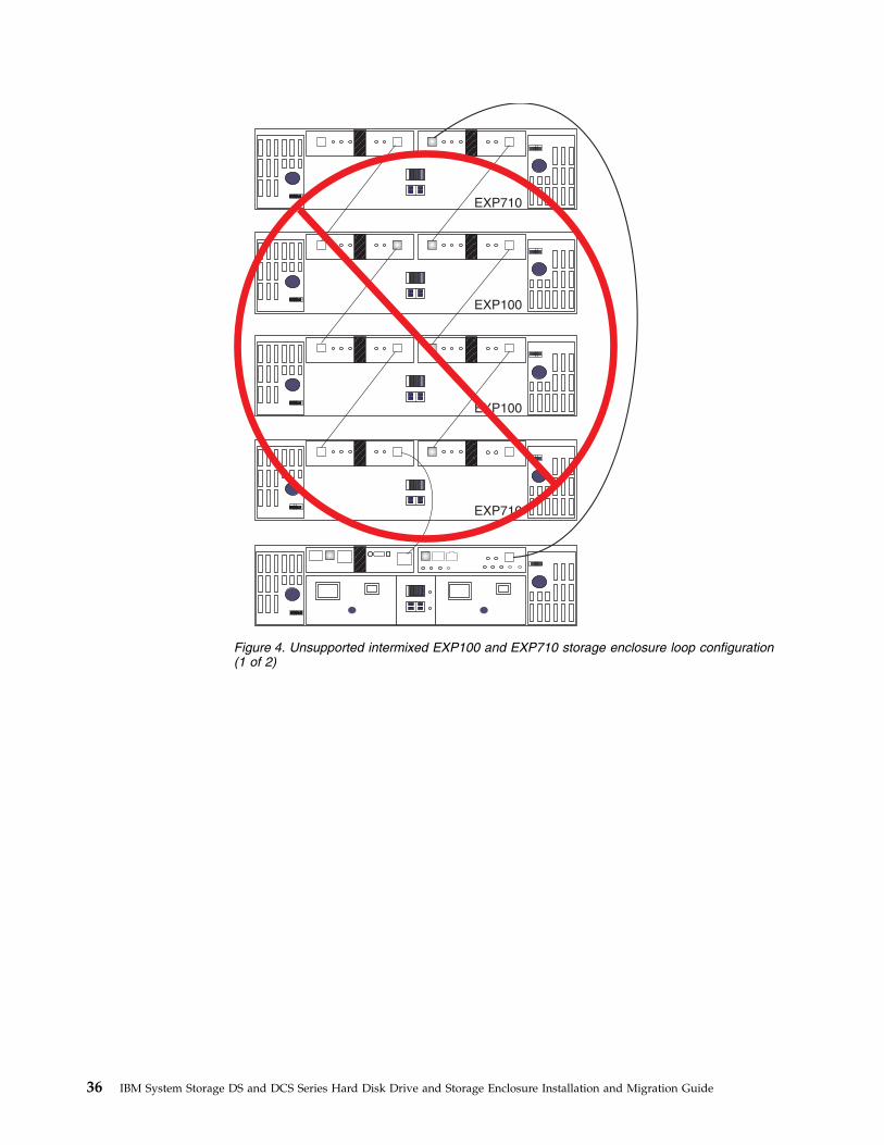
EXP710
EXP100
EXP100
EXP710
Figure 4. Unsupported intermixed EXP100 and EXP710 storage enclosure loop configuration(1 of 2)
36 IBM System Storage DS and DCS Series Hard Disk Drive and Storage Enclosure Installation and Migration Guide

Intermixing EXP395 and EXP810 storage enclosuresYou can attach the EXP810 storage enclosure to the DS3950 storage subsystem onlyafter you purchase the Attach EXP810 storage enclosure to DS3950 Activationoption and activate it in the DS3950 storage subsystem.
When you cable an EXP810 storage enclosure behind a DS5020 storage subsystem,the EXP810 storage enclosure is cabled in the same manner as an EXP395 storageenclosure. There are no special requirements to cable a mix of EXP810 and EXP395storage enclosures behind a DS3950 storage subsystem.
Intermixing EXP520 and EXP810 storage enclosuresYou can attach the EXP810 storage enclosure to the DS5020 storage subsystem onlyafter you purchase the Attach EXP810 storage enclosure to DS5020 Activationoption and activate it in the storage subsystem.
When you cable an EXP810 storage enclosure behind a DS5020 storage subsystem,the EXP810 storage enclosure is cabled in the same manner as an EXP520 storageenclosure. There are no special requirements to cable a mix of EXP810 and EXP520storage enclosures behind a DS5020 storage subsystem.
EXP710
EXP100
EXP710
EXP100
Figure 5. Unsupported intermixed EXP100 and EXP710 storage enclosure loop configuration(2 of 2)
Chapter 1. Prerequisites to adding capacity and hard disk drive migration 37

Intermixing EXP810 with EXP100 and EXP710 storageenclosures
With controller firmware 6.23.xx.xx.xx or later, DS4300, DS4500, DS4700, andDS4800 storage subsystems support the intermixing of the EXP810 storageenclosure with EXP710 and EXP100 storage enclosures.
Although storage enclosures (EXP710 and EXP810 storage enclosures) do not haveto be grouped by drive enclosure type, group them by enclosure type in aredundant drive channel pair to simplify maintenance and troubleshooting. Inaddition, the EXP810 storage enclosure link rate switch must be set at 2 Gbps.
Notes:
1. The link rate setting becomes effective only after the EXP810 storage enclosureis turned on. Do not change the setting while the EXP810 storage enclosure isoperational. Schedule a time to shut down the entire DS4000 configuration tochange the link rate speed setting.
2. You must follow specific restrictions when you intermix EXP100 with EXP710and EXP810 storage enclosures in a DS4700 or DS4800 storage subsystem. See“Cabling EXP100, EXP710, and EXP810 storage enclosures in DS4700 andDS4800 configurations” on page 110 for details.
There are limits to the number of Fibre Channel hard disk drives that you canconfigure in redundant drive channel pairs. The maximum number of drivesdictates a fixed number of supported EXP100 and EXP710 and EXP810 storageenclosure combinations. Table 17 lists the number of EXP100, EXP710, and EXP810storage enclosures that you can combine for use in a single redundant drivechannel/loop pair. The table assumes that a DS4000 storage subsystem is generallycapable of addressing the maximum of 112 Fibre Channel hard disk drives for eachredundant drive channel/loop pair.
Table 17. Supported EXP810, EXP710, and EXP100 storage enclosure combinations per redundant drive channel/looppair in a DS4000 configuration with no internal drive bays configuration
Total EXP810 storageenclosures perredundant drivechannel/loop pair
Total EXP710, EXP100,or both storageenclosures perredundant drivechannel/loop pair
Maximum storageexpansion drives perredundant drivechannel/loop pair
Maximum drives in mixed EXP100,EXP710, and EXP810 drive channel/looppair
0 8 8 112
1 6 7 100
2 5 7 102
3 4 7 104
4 3 7 106
5 2 7 108
6 1 7 110
7 0 7 112
Do not mix EXP100, EXP710, and EXP810 storage enclosures together in the sameredundant drive channel/loop pair if you plan to operate the EXP810 storageenclosure at a higher speed. Connect all of the EXP710 and EXP100 storageenclosures to a redundant drive channel pair and all of the EXP810 storageenclosures to the other redundant drive channel pair in a DS4800 configuration.
38 IBM System Storage DS and DCS Series Hard Disk Drive and Storage Enclosure Installation and Migration Guide

Table 18 shows the supported EXP810 and EXP710 storage enclosures combinationsper redundant drive channel/loop pair in a DS4700 Express configuration. Thetable assumes that a DS4700 Express storage subsystem is generally capable ofaddressing the maximum of 112 Fibre Channel hard disk drives for each redundantdrive channel/loop pair.
The DS4700 Express storage subsystem (with its internal drives) is already countedas one enclosure against the maximum number of enclosures that can be in aredundant channel/loop pair.
Table 18. Supported EXP810 and EXP710/EXP100 storage enclosure combinations per redundant drive channel/looppair in a DS4700 Express storage subsystem
EXP810 storageenclosures
Total drives inthe EXP810storageenclosures
EXP710 andEXP100 storageenclosures
Total drives inthe EXP100 andEXP710 storageenclosures
Total drives inthe DS4700Express storagesubsystem
Total drives in a mixedEXP710/EXP100 and EXP810drive loop
0 0 6 84 16 100
1 16 5 70 16 102
2 32 4 56 16 104
3 48 3 42 16 106
4 64 2 28 16 108
5 80 1 14 16 110
6 96 0 0 16 112
Chapter 1. Prerequisites to adding capacity and hard disk drive migration 39
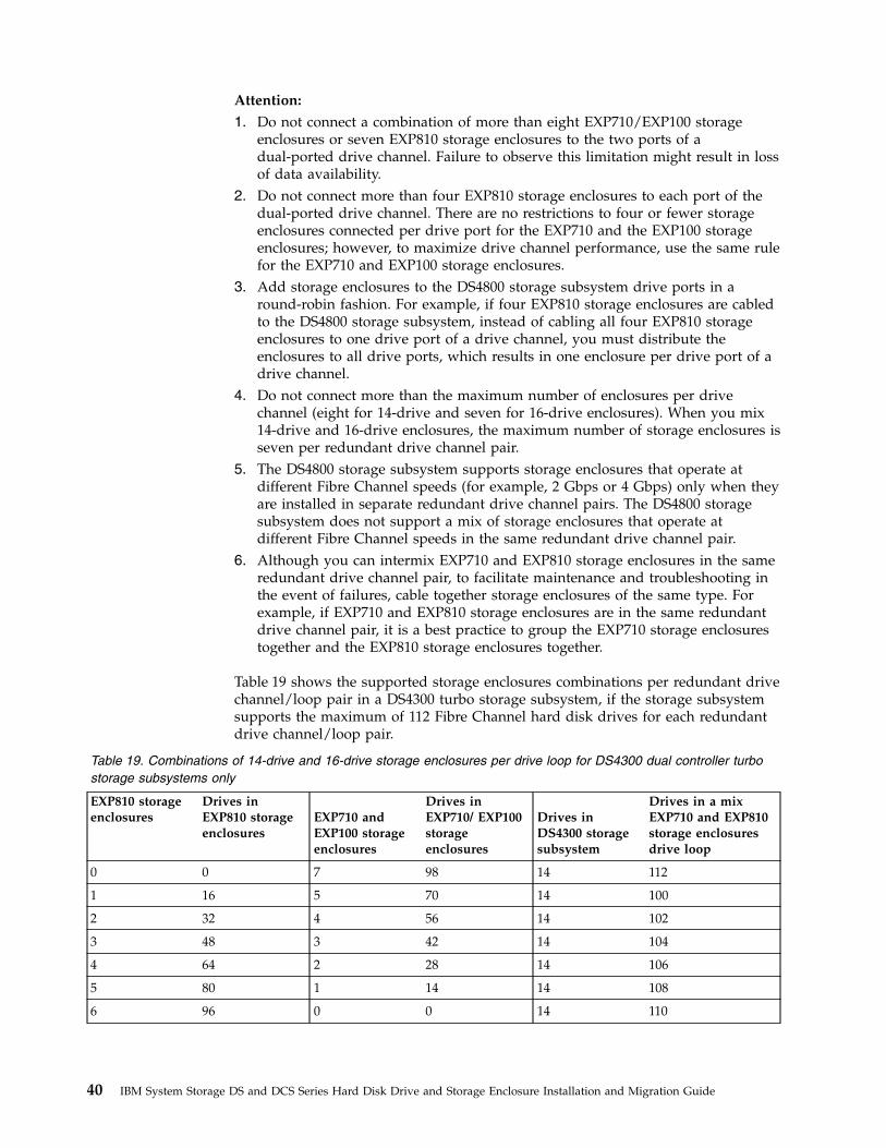
Attention:
1. Do not connect a combination of more than eight EXP710/EXP100 storageenclosures or seven EXP810 storage enclosures to the two ports of adual-ported drive channel. Failure to observe this limitation might result in lossof data availability.
2. Do not connect more than four EXP810 storage enclosures to each port of thedual-ported drive channel. There are no restrictions to four or fewer storageenclosures connected per drive port for the EXP710 and the EXP100 storageenclosures; however, to maximize drive channel performance, use the same rulefor the EXP710 and EXP100 storage enclosures.
3. Add storage enclosures to the DS4800 storage subsystem drive ports in around-robin fashion. For example, if four EXP810 storage enclosures are cabledto the DS4800 storage subsystem, instead of cabling all four EXP810 storageenclosures to one drive port of a drive channel, you must distribute theenclosures to all drive ports, which results in one enclosure per drive port of adrive channel.
4. Do not connect more than the maximum number of enclosures per drivechannel (eight for 14-drive and seven for 16-drive enclosures). When you mix14-drive and 16-drive enclosures, the maximum number of storage enclosures isseven per redundant drive channel pair.
5. The DS4800 storage subsystem supports storage enclosures that operate atdifferent Fibre Channel speeds (for example, 2 Gbps or 4 Gbps) only when theyare installed in separate redundant drive channel pairs. The DS4800 storagesubsystem does not support a mix of storage enclosures that operate atdifferent Fibre Channel speeds in the same redundant drive channel pair.
6. Although you can intermix EXP710 and EXP810 storage enclosures in the sameredundant drive channel pair, to facilitate maintenance and troubleshooting inthe event of failures, cable together storage enclosures of the same type. Forexample, if EXP710 and EXP810 storage enclosures are in the same redundantdrive channel pair, it is a best practice to group the EXP710 storage enclosurestogether and the EXP810 storage enclosures together.
Table 19 shows the supported storage enclosures combinations per redundant drivechannel/loop pair in a DS4300 turbo storage subsystem, if the storage subsystemsupports the maximum of 112 Fibre Channel hard disk drives for each redundantdrive channel/loop pair.
Table 19. Combinations of 14-drive and 16-drive storage enclosures per drive loop for DS4300 dual controller turbostorage subsystems only
EXP810 storageenclosures
Drives inEXP810 storageenclosures
EXP710 andEXP100 storageenclosures
Drives inEXP710/ EXP100storageenclosures
Drives inDS4300 storagesubsystem
Drives in a mixEXP710 and EXP810storage enclosuresdrive loop
0 0 7 98 14 112
1 16 5 70 14 100
2 32 4 56 14 102
3 48 3 42 14 104
4 64 2 28 14 106
5 80 1 14 14 108
6 96 0 0 14 110
40 IBM System Storage DS and DCS Series Hard Disk Drive and Storage Enclosure Installation and Migration Guide
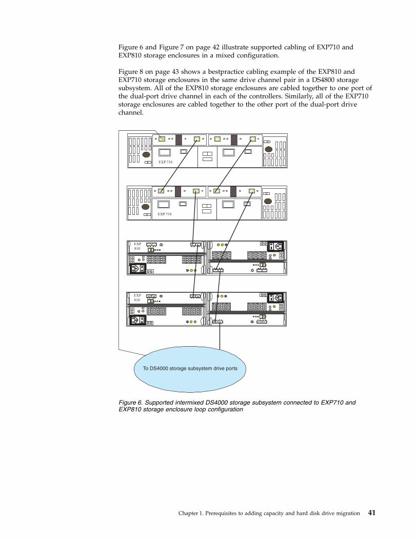
Figure 6 and Figure 7 on page 42 illustrate supported cabling of EXP710 andEXP810 storage enclosures in a mixed configuration.
Figure 8 on page 43 shows a bestpractice cabling example of the EXP810 andEXP710 storage enclosures in the same drive channel pair in a DS4800 storagesubsystem. All of the EXP810 storage enclosures are cabled together to one port ofthe dual-port drive channel in each of the controllers. Similarly, all of the EXP710storage enclosures are cabled together to the other port of the dual-port drivechannel.
To DS4000 storage subsystem drive ports
3 6
63
EXP
810
3 6
63
EXP
810
EXP 710
EXP 710
Figure 6. Supported intermixed DS4000 storage subsystem connected to EXP710 andEXP810 storage enclosure loop configuration
Chapter 1. Prerequisites to adding capacity and hard disk drive migration 41

EXP810
EXP810
36 EXP810
EXP810
36
36
36
EXP710
EXP710
... to DS4000 StorageSubsystem drive ports
Figure 7. Supported intermixed DS4000 storage subsystem connected to EXP710 andEXP810 storage enclosure loop configuration
42 IBM System Storage DS and DCS Series Hard Disk Drive and Storage Enclosure Installation and Migration Guide

Intermixing EXP810 and EXP5000 storage enclosuresFor client investment protection, you can migrate existing EXP810 storageenclosures from currently installed DS4700 or DS4800 storage subsystems to attachto a DS5100 or DS5300 storage subsystem. A request for price quote (RPQ)approval is required for support of all migration configurations. You must givespecial consideration to proper firmware levels and careful coordination ofdifferences in warranty and maintenance terms. You can submit an RPQ throughthe normal request process. Purchase of new EXP810 storage enclosures to attachto DS5100 or DS5300 storage subsystem is not supported or configurable ineConfig.
When you cable EXP810 storage enclosures behind a DS5100 or DS5300 storagesubsystem, EXP810 storage enclosures are cabled in the same manner as EXP5000storage enclosures. There are no special requirements to cable a mix of EXP810 andEXP5000 storage enclosures behind a DS5100 or DS5300 storage subsystem.
Intermixing EXP5000 and EXP5060 storage enclosuresThe following notes describe information that you must consider when youconnect the EXP5000 and EXP5060 storage enclosures in the same storagesubsystem redundant drive loop/channel:v Use the non-trunk cabling scheme to connect the EXP5000 and EXP5060 storage
enclosure to the DS5100 or DS5300 drive channel/ports.v A maximum of three EXP5000 storage enclosures and one EXP5060 storage
enclosure can be connected in the same redundant drive loop/channel.
Controller A
Controller B
58
8 5
3 6
63
EXP
810
3 6
63
EXP
810
EXP810 drive channel/loop EXP710 drive channel/loop
3 6
63
EXP
810
EXP 710
EXP 710
EXP 710
Figure 8. Best practice intermixed DS4000 storage subsystem connected to EXP710 andEXP810 storage enclosure loop configuration
Chapter 1. Prerequisites to adding capacity and hard disk drive migration 43

v Cable the EXP5000 and EXP5060 storage enclosures behind the same pair ofdrive channel ports only if necessary. Best practice is to dedicate the full drivechannel (two ports per controller) for cabling the EXP5060 storage enclosure tothe storage subsystem controllers to allow the trunked-cabling scheme to beused.
v If the Up to 8 EXP5060 storage enclosure attached feature pack is enabled, theDS5100 or DS5300 storage subsystem supports only EXP5060 storage enclosuresin the configuration.
Figure 9 shows a bestpractice cabling example EXP5000 and EXP5060 storageenclosure cabled in the same redundant drive/loop channel.
Intermixing storage enclosures for DS4000 and DS5000storage subsystems
This section describes the steps to intermix storage enclosures.
1B1A 2B 2A
1B 1A
1B1A 2B 2A
1B 1A
1B1A 2B 2A
1B 1A
1A 1B
1A 1B
2A 2B
2A 2B
ESM A
ESM B
Ch5 Ch6 Ch7 Ch8
Ch1 Ch2 Ch3 Ch4
P8 P7 P6 P5 P4 P3 P2 P1
P8P7P6P5P4P3P2P1
Figure 9. Best practice intermixed EXP5000 and EXP5060 storage enclosure drive/loop cableconfiguration
44 IBM System Storage DS and DCS Series Hard Disk Drive and Storage Enclosure Installation and Migration Guide

The following notes describe information that you must consider when youconnect storage enclosures to the storage subsystem:v The DS4000 storage subsystem supports the connection of a maximum of two
redundant drive loop pairs. The DS5000 storage subsystem supports a maximumof four redundant drive loop pairs. The maximum number of storage enclosuresper drive loop depends on the type of storage enclosure and whetherintermixing storage enclosures of different drive bays is permitted.
v The maximum number of drives in a storage subsystem configuration varies bymodel. Some models require additional feature option purchases to enable youto connect the maximum number storage enclosures behind it.
v When you connect the storage enclosures to drive mini hubs, do not use allports in each of the drive mini hubs in the DS4400 or DS4500 storage subsystem.Connect the Fibre Channel cable to only one port of the drive mini hub andleave the other port unoccupied. However, when you connect the storageenclosures to drive channel ports (such as on the DS4200, DS4700, DS4800,DS5020, DS5100, and DS5300 storage subsystem), use all ports in each of thedrive channels. Figure 10 illustrates connecting eight storage enclosures to theDS5000 storage subsystem. The eight enclosures are connected to use all of thedrive channel ports in the DS5000 storage subsystem instead of stacking thestorage enclosures behind a subset of drive channel ports.
v When you cable different types of storage enclosures, if possible, do not mixdifferent types of storage enclosures in the same redundant drive loop pair. Also,when you mix different types of storage enclosures in the same drive channelpair, the link rate setting must be the same for each storage enclosure. IBM doesnot support different enclosure speed settings in the same drive loop.
3
3 6
63
EXP810/EXP5000 3 6
63
EXP810/EXP5000
3 6
63
EXP810/EXP5000
2
4
1
3 6
63
EXP810/EXP5000
3 6
63
EXP810/EXP5000 3 6
63
EXP810/EXP5000
3 6
63
EXP810/EXP5000 3 6
63
EXP810/EXP5000
5 6
7 8
Figure 10. Use all drive channel ports when connecting storage enclosures
Chapter 1. Prerequisites to adding capacity and hard disk drive migration 45

The following notes describe information that you must consider when youconnect storage enclosures to the storage subsystem:v Ensure that the enclosure ID of each enclosure in a storage subsystem
configuration is unique. For more information, see “Setting enclosure IDs forenclosures in DS4000 and DS5000 storage subsystems” on page 29.
v If it is not possible to avoid mixing different enclosure types in the sameredundant drive loop pair, this rule must be strictly observed. When you mixEXP810 and EXP710 storage enclosures in the same drive loop with EXP100storage enclosures, all of the EXP810 and EXP710 storage enclosures must begrouped together with the EXP100 storage enclosures connected to either end ofthe storage enclosure group. With this grouping, the controller firmwareidentifies the EXP810 and EXP710 storage enclosures as the same enclosure type(switched disk storage enclosure, which has an ESM-embedded Fibre Channelloop switch). These two enclosure models must be grouped together if they arecontained within a drive loop.
Note: You must cable all of the EXP810 storage enclosures together, followed byall of the EXP710 storage enclosures. Figure 12 on page 49 and Figure 13 on page50 are examples of correctly cabling the intermix of EXP100 with EXP810 andEXP710 storage enclosures. Figure 14 on page 51 and Figure 15 on page 52 areexamples of incorrectly cabling the intermix of these enclosures. One shows theEXP100 storage enclosures cabled between the EXP810 and EXP710 storageenclosures, and the other shows the EXP810 and EXP710 storage enclosuresintermingled.
v The storage subsystem drive expansion port must always be connected to theEXP420/EXP520/EXP810/EXP5000 storage enclosure port 1B. Figure 16 on page53 is an example of correctly cabling the EXP420/EXP520/EXP810/EXP5000storage enclosure 1B ports to the storage subsystem drive expansion port.Figure 17 on page 54 is an example of incorrect cabling that shows theconnection from the storage subsystem drive expansion port to the incorrectEXP420/EXP520/EXP810/EXP5000 storage enclosure port, labeled 1A.
v The storage subsystem drive expansion port must always be connected to theleft ESM In port of the last enclosure in a redundant drive loop pair. In addition,the drive expansion port must always be connected to the right ESM Out port ofthe first enclosure in a redundant drive loop/channel pair. The exception to thisrule is when an EXP100 storage enclosure is the first enclosure directlyconnected to controller A of a DS4700 or DS4800 storage subsystem. In this case,cable from the storage subsystem controller drive port A to the OUT port on theleft ESM (ESM A) of the EXP100 storage enclosure. See “Cabling EXP100,EXP710, and EXP810 storage enclosures in DS4700 and DS4800 configurations”on page 110 for details.Figure 18 on page 55 shows this correct cabling to the 10- or 14-drive storageenclosure ESM ports.
General rules for cabling storage enclosuresThe following notes describe information that you must consider when youconnect storage enclosures to the storage subsystem:v The DS4000 storage subsystem supports the connection of a maximum of two
redundant drive loop pairs. The DS5000 storage subsystem supports a maximumof four redundant drive loop pairs. The maximum number of storage enclosuresper drive loop depends on the type of storage enclosure and whetherintermixing storage enclosures of different drive bays is permitted.
46 IBM System Storage DS and DCS Series Hard Disk Drive and Storage Enclosure Installation and Migration Guide
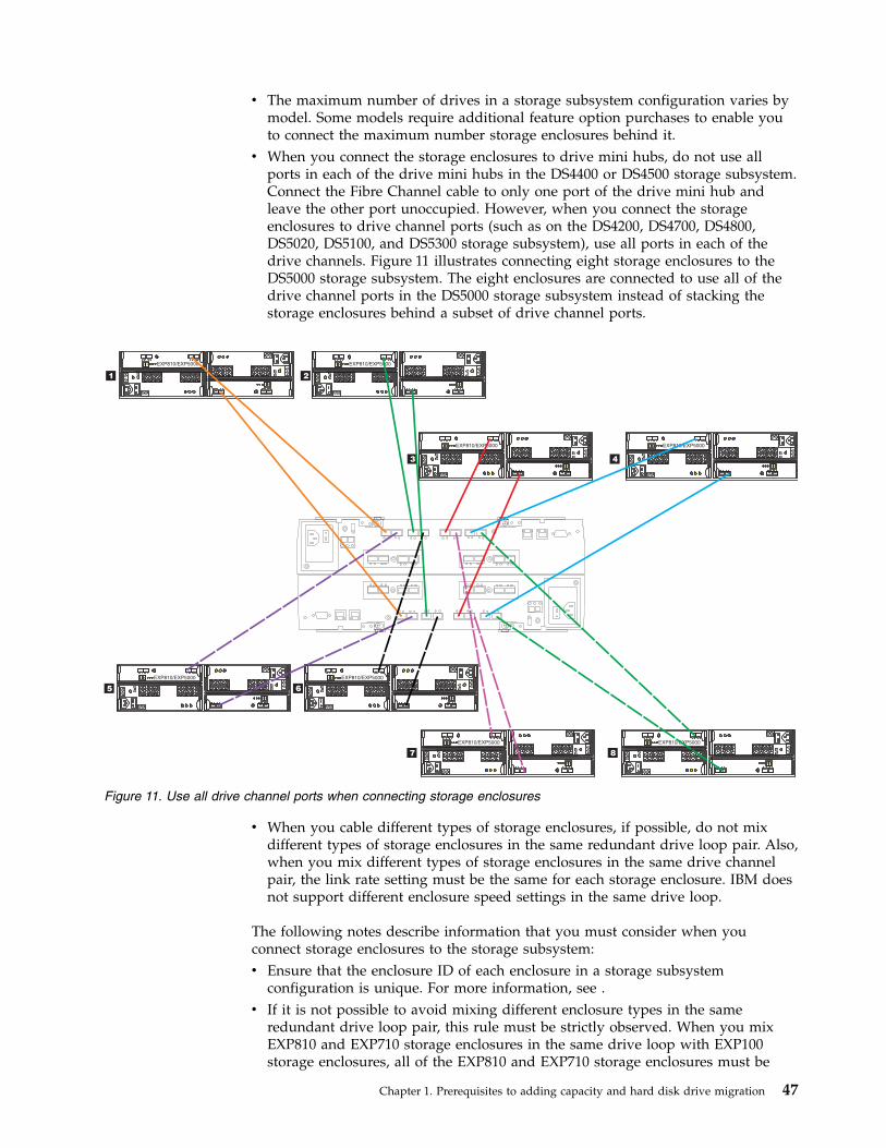
v The maximum number of drives in a storage subsystem configuration varies bymodel. Some models require additional feature option purchases to enable youto connect the maximum number storage enclosures behind it.
v When you connect the storage enclosures to drive mini hubs, do not use allports in each of the drive mini hubs in the DS4400 or DS4500 storage subsystem.Connect the Fibre Channel cable to only one port of the drive mini hub andleave the other port unoccupied. However, when you connect the storageenclosures to drive channel ports (such as on the DS4200, DS4700, DS4800,DS5020, DS5100, and DS5300 storage subsystem), use all ports in each of thedrive channels. Figure 11 illustrates connecting eight storage enclosures to theDS5000 storage subsystem. The eight enclosures are connected to use all of thedrive channel ports in the DS5000 storage subsystem instead of stacking thestorage enclosures behind a subset of drive channel ports.
v When you cable different types of storage enclosures, if possible, do not mixdifferent types of storage enclosures in the same redundant drive loop pair. Also,when you mix different types of storage enclosures in the same drive channelpair, the link rate setting must be the same for each storage enclosure. IBM doesnot support different enclosure speed settings in the same drive loop.
The following notes describe information that you must consider when youconnect storage enclosures to the storage subsystem:v Ensure that the enclosure ID of each enclosure in a storage subsystem
configuration is unique. For more information, see .v If it is not possible to avoid mixing different enclosure types in the same
redundant drive loop pair, this rule must be strictly observed. When you mixEXP810 and EXP710 storage enclosures in the same drive loop with EXP100storage enclosures, all of the EXP810 and EXP710 storage enclosures must be
3
3 6
63
EXP810/EXP5000 3 6
63
EXP810/EXP5000
3 6
63
EXP810/EXP5000
2
4
1
3 6
63
EXP810/EXP5000
3 6
63
EXP810/EXP5000 3 6
63
EXP810/EXP5000
3 6
63
EXP810/EXP5000 3 6
63
EXP810/EXP5000
5 6
7 8
Figure 11. Use all drive channel ports when connecting storage enclosures
Chapter 1. Prerequisites to adding capacity and hard disk drive migration 47

grouped together with the EXP100 storage enclosures connected to either end ofthe storage enclosure group. With this grouping, the controller firmwareidentifies the EXP810 and EXP710 storage enclosures as the same enclosure type(switched disk storage enclosure, which has an ESM-embedded Fibre Channelloop switch). These two enclosure models must be grouped together if they arecontained within a drive loop.
Note: You must cable all of the EXP810 storage enclosures together, followed byall of the EXP710 storage enclosures. and are examples of correctly cabling theintermix of EXP100 with EXP810 and EXP710 storage enclosures. and areexamples of incorrectly cabling the intermix of these enclosures. One shows theEXP100 storage enclosures cabled between the EXP810 and EXP710 storageenclosures, and the other shows the EXP810 and EXP710 storage enclosuresintermingled.
v The storage subsystem drive expansion port must always be connected to theEXP420/EXP520/EXP810/EXP5000 storage enclosure port 1B. is an example ofcorrectly cabling the EXP420/EXP520/EXP810/EXP5000 storage enclosure 1Bports to the storage subsystem drive expansion port. is an example of incorrectcabling that shows the connection from the storage subsystem drive expansionport to the incorrect EXP420/EXP520/EXP810/EXP5000 storage enclosure port,labeled 1A.
v The storage subsystem drive expansion port must always be connected to theleft ESM In port of the last enclosure in a redundant drive loop pair. In addition,the drive expansion port must always be connected to the right ESM Out port ofthe first enclosure in a redundant drive loop/channel pair. The exception to thisrule is when an EXP100 storage enclosure is the first enclosure directlyconnected to controller A of a DS4700 or DS4800 storage subsystem. In this case,cable from the storage subsystem controller drive port A to the OUT port on theleft ESM (ESM A) of the EXP100 storage enclosure. See for details.shows this correct cabling to the 10- or 14-drive storage enclosure ESM ports.
Storage enclosure cabling diagramsThe following diagrams illustrate the information that is provided in “Generalrules for cabling storage enclosures” on page 46. The controllers that are illustratedin the cabling diagrams do not represent any specific storage subsystem.
48 IBM System Storage DS and DCS Series Hard Disk Drive and Storage Enclosure Installation and Migration Guide
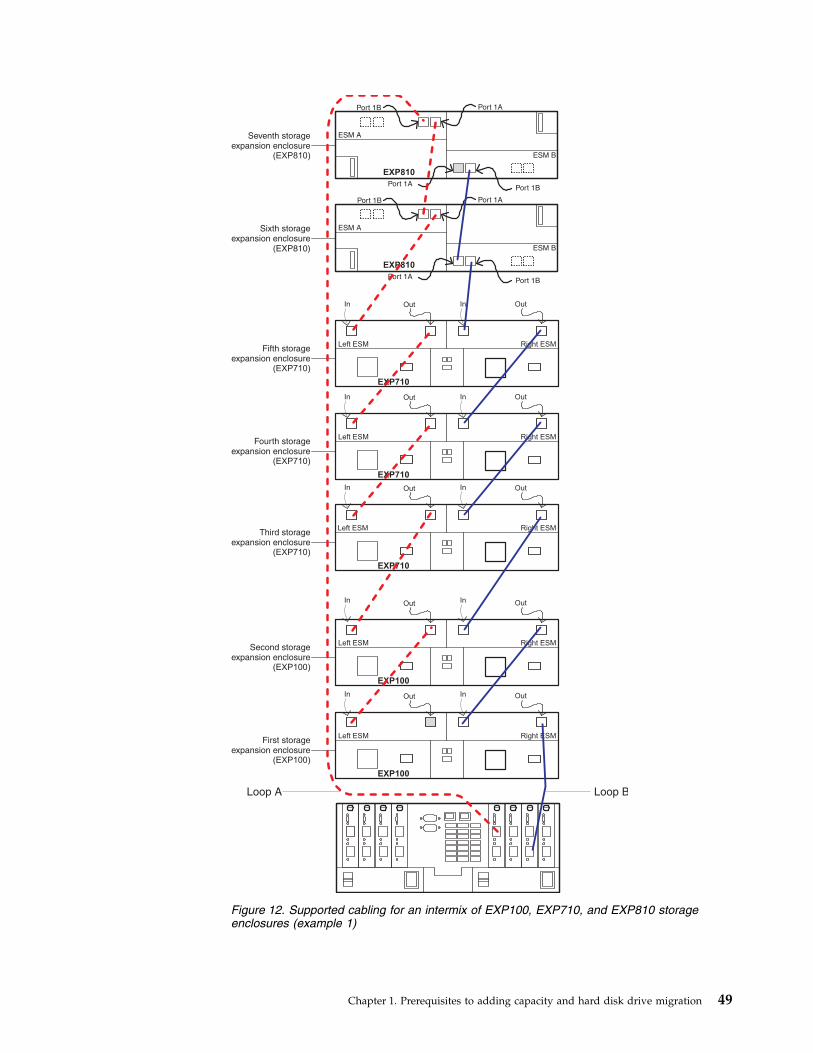
Right ESMLeft ESM
Out Out
EXP100
Second storageexpansion enclosure
(EXP100)
Right ESMLeft ESM
Out Out
EXP100
First storageexpansion enclosure
(EXP100)
Right ESMLeft ESM
Out Out
EXP710
Fifth storageexpansion enclosure
(EXP710)
Right ESMLeft ESM
Out Out
EXP710
Fourth storageexpansion enclosure
(EXP710)
Right ESMLeft ESM
Out OutIn
EXP710
Third storageexpansion enclosure
(EXP710)
Loop B
EXP810
ESM B
ESM A
Port 1BPort 1A
Port 1APort 1B
Sixth storageexpansion enclosure
(EXP810)
EXP810
ESM B
ESM A
Port 1BPort 1A
Port 1APort 1B
Seventh storageexpansion enclosure
(EXP810)
In
In
In
In
Loop A
In
In
In
In
In
Figure 12. Supported cabling for an intermix of EXP100, EXP710, and EXP810 storageenclosures (example 1)
Chapter 1. Prerequisites to adding capacity and hard disk drive migration 49

Right ESMLeft ESM
Out Out
EXP100
Second storageexpansion enclosure
(EXP100)
Right ESMLeft ESM
Out Out
EXP100
First storageexpansion enclosure
(EXP100)
Loop B
EXP810
ESM B
ESM A
Port 1BPort 1A
Port 1APort 1B
Third storageexpansion enclosure
(EXP810)
EXP810
ESM B
ESM A
Port 1BPort 1A
Port 1APort 1B
Fourth storageexpansion enclosure
(EXP810)
In
In
Loop A
In
In
Right ESMLeft ESM
Out Out
EXP710
Seventh storageexpansion enclosure
(EXP710)
Right ESMLeft ESM
Out Out
EXP710
Sixth storageexpansion enclosure
(EXP710)
Right ESMLeft ESM
Out OutIn
EXP710
Fifth storageexpansion enclosure
(EXP710)
In
In
In
In
In
Figure 13. Supported cabling for an intermix of EXP100, EXP710, and EXP810 storageenclosures (example 2)
50 IBM System Storage DS and DCS Series Hard Disk Drive and Storage Enclosure Installation and Migration Guide
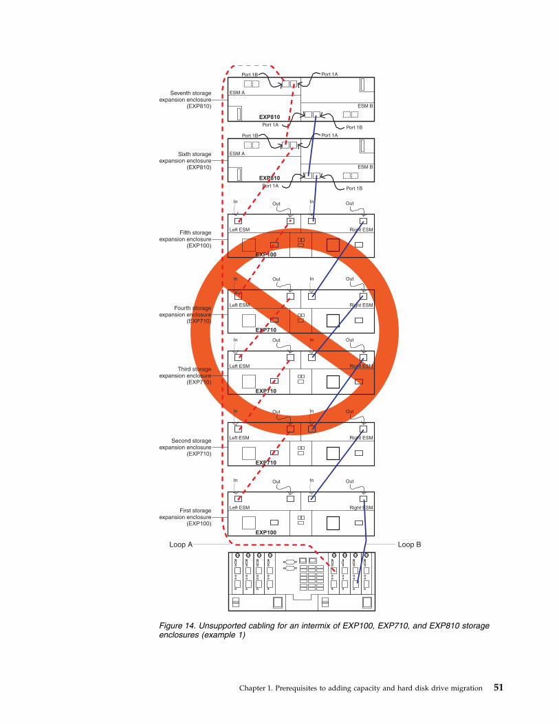
Right ESMLeft ESM
Out Out
EXP100
First storageexpansion enclosure
(EXP100)
Loop B
EXP810
ESM B
ESM A
Port 1BPort 1A
Port 1APort 1B
Sixth storageexpansion enclosure
(EXP810)
EXP810
ESM B
ESM A
Port 1BPort 1A
Port 1APort 1B
Seventh storageexpansion enclosure
(EXP810)
In
Loop A
In
Right ESMLeft ESM
Out Out
EXP100
Fifth storageexpansion enclosure
(EXP100)
InIn
Right ESMLeft ESM
Out Out
EXP710
Fourth storageexpansion enclosure
(EXP710)
Right ESMLeft ESM
Out Out
EXP710
Third storageexpansion enclosure
(EXP710)
Right ESMLeft ESM
Out OutIn
EXP710
Second storageexpansion enclosure
(EXP710)
In
In
In
In
In
Figure 14. Unsupported cabling for an intermix of EXP100, EXP710, and EXP810 storageenclosures (example 1)
Chapter 1. Prerequisites to adding capacity and hard disk drive migration 51
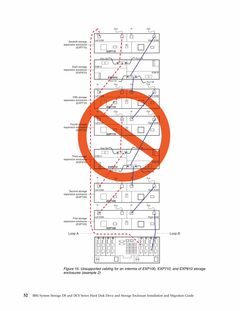
Right ESMLeft ESM
Out Out
EXP100
First storageexpansion enclosure
(EXP100)
Loop B
EXP810
ESM B
ESM A
Port 1BPort 1A
Port 1APort 1B
Third storageexpansion enclosure
(EXP810)
EXP810
ESM B
ESM A
Port 1BPort 1A
Port 1APort 1B
Sixth storageexpansion enclosure
(EXP810)
In
Loop A
In
Right ESMLeft ESM
Out Out
EXP100
Second storageexpansion enclosure
(EXP100)
InIn
Right ESMLeft ESM
Out Out
EXP710
Fifth storageexpansion enclosure
(EXP710)
Right ESMLeft ESM
Out Out
EXP710
Fourth storageexpansion enclosure
(EXP710)
Right ESMLeft ESM
Out OutIn
EXP710
Seventh storageexpansion enclosure
(EXP710)
In
In
In
In
In
Figure 15. Unsupported cabling for an intermix of EXP100, EXP710, and EXP810 storageenclosures (example 2)
52 IBM System Storage DS and DCS Series Hard Disk Drive and Storage Enclosure Installation and Migration Guide

EXP810
ESM B
ESM A
Port 1BPort 1A
Port 1APort 1B
First storageexpansion enclosure
(EXP810)
EXP810
ESM B
ESM A
Port 1BPort 1A
Port 1APort 1B
Last storageexpansion enclosure
(EXP810)
Other storageexpansion enclosures
Figure 16. Supported cabling to EXP420/EXP520/EXP810/EXP5000 storage enclosure port1B
Chapter 1. Prerequisites to adding capacity and hard disk drive migration 53

EXP810
ESM B
ESM A
Port 1BPort 1A
Port 1APort 1B
First storageexpansion enclosure
(EXP810)
EXP810
ESM B
ESM A
Port 1BPort 1A
Port 1APort 1B
Last storageexpansion enclosure
(EXP810)
Other storageexpansion enclosures
Figure 17. Unsupported cabling to the EXP420/EXP520/EXP810/EXP5000 storage enclosureport
54 IBM System Storage DS and DCS Series Hard Disk Drive and Storage Enclosure Installation and Migration Guide

First storageexpansion enclosure
( )EXP500/100/7x0
Last storageexpansion enclosure
(EXP500/100/7x0)
Right ESMLeft ESM
Out OutIn
Right ESMLeft ESM
Out OutIn
In
In
EXP500/100/7x0
EXP500/100/7x0
Other storageexpansion enclosures
Figure 18. Supported cabling to the EXP500/EXP100/EXP700/EXP710 storage enclosureports
Chapter 1. Prerequisites to adding capacity and hard disk drive migration 55

56 IBM System Storage DS and DCS Series Hard Disk Drive and Storage Enclosure Installation and Migration Guide

Chapter 2. Adding or migrating hard disk drives
To add hard disk drives to the storage subsystem configuration or place the drives(that made up a RAID array) in different drive bays, see the following sections:v To add new hard disk drives to an existing storage subsystem, see “Adding new
hard disk drives” on page 58.
Note: Any hard disk drive might contain configuration data. Unless you intendto migrate drives from another storage subsystem (retaining its configurationdata), always use this procedure to add hard disk drives to an existing storagesubsystem configuration.
v To add new unassigned drives in different drive bays, see “Adding new harddisk drives” on page 58.
v To migrate drives from one storage subsystem configuration to another, see“Migrating hard disk drives” on page 59.
v To rearrange the drives (that made up a RAID array) in different drive bays inthe same storage subsystem, see “Migrating arrays within the same storagesubsystem” on page 66.
Before you begin, review Chapter 1, “Prerequisites to adding capacity and harddisk drive migration,” on page 1 and “General rules for cabling storageenclosures” on page 46.
ConsiderationsThe following notes describe information that you must consider when you add ahard disk drive to a controller or a storage enclosure:v Observe proper electrostatic discharge (ESD) procedures when you handle
electronic equipment. For more information, see “Handling static-sensitivedevices” on page 58.
v Never alter the physical configuration of a storage subsystem while the power isturned off unless you are instructed to do so as part of a configurationprocedure. Specifically, never attach storage components to, or remove storagecomponents from, a configured storage subsystem while the power is turned off.
v Updated readme files contain important configuration and proceduralinformation that supersede information in this document. Always check thereadme file before you perform any procedure or activity described in thisdocument. To access the most recent readme file, see “Finding Storage Managersoftware, controller firmware, and readme files” on page 147.
v Before you migrate hard disk drives, complete the following steps to establishdrive model compatibility:1. Check the drive CRU form factor options.2. If the form factors are not the same, there are no replacement parts such as
bezels and drive trays. For more information, see the announcement letter,the Installation, User's, and Maintenance Guide for your storage subsystem, andyour IBM marketing representative or authorized reseller.
3. If the form factors are the same, check to determine whether the drive issupported by the storage subsystem.
4. Ensure that the drive can operate at the storage subsystem driveloop/channel Fibre Channel or SAS speed. For more information, see the
© Copyright IBM Corp. 2008, 2013 57
documentation for your storage subsystem, the storage subsystem profile, theannouncement letters at the IBM website, or contact your IBM marketingrepresentative or authorized reseller.
v You can migrate drives from systems that have controller firmware level 6.xx orearlier to storage subsystems that have controller firmware level 7.xx or later, orDS Storage Manager software version 10.xx or later. (For information about thetype of logical drives that can be migrated, see item 12 on page 12.) However,you cannot migrate drives from systems with controller firmware version 7.xx orlater to systems with controller firmware level 6.xx or earlier.Ensure that the controller firmware level of both the source and target storagesubsystems. Upgrade both the source and target storage subsystems to the samecontroller firmware if possible.
Handling static-sensitive devices
Attention: Static electricity can damage electronic devices and your system. Toavoid damage, keep static-sensitive devices in their static-protective packages untilyou are ready to install them.
To reduce the possibility of electrostatic discharge (ESD), observe the followingprecautions:v Limit your movement. Movement can cause static electricity to build up around
you.v Handle the device carefully, holding it by its edges or its frame.v Do not touch solder joints, pins, or exposed printed circuitry.v Do not leave the device where others can handle and damage it.v While the device is still in its static-protective package, touch it to an unpainted
metal part of the system unit for at least 2 seconds. This drains static electricityfrom the package and from your body.
v Remove the device from its package and install it directly into the system unitwithout setting down the device. If it is necessary to set down the device, put itback into its static-protective package. Do not place the device on the systemunit cover or on a metal surface. Take additional care when you handle devicesduring cold weather. Heating reduces indoor humidity and increases staticelectricity.
Adding new hard disk drivesThis section describes the procedure to add new hard disk drives to empty drivebays either in storage subsystems or storage enclosures. If you plan to add a useddrive, ensure that there is no configuration data on the drive that you need topreserve. A used drive is a drive that is removed from an existing storagesubsystem. It might be configured as part of the RAID array. Add drives to astorage subsystem only while the power is turned on and the storage subsystem isin Optimal state. For more information, see the Recovery Guru function in theStorage Subsystem Management window, the Problem Determination Guide, or“Bringing storage subsystems and drive loops into optimal state” on page 21.
Important:
v Do not perform this procedure if you are migrating drives from another DS4000storage subsystem. This procedure deletes the logical drive configuration in the
58 IBM System Storage DS and DCS Series Hard Disk Drive and Storage Enclosure Installation and Migration Guide
migrated hard disk drives. Instead, see the instructions in “Migrating storageenclosures with hard disk drives that have defined logical drive configurations”on page 79.
v Perform the prerequisites that are described in Chapter 1, “Prerequisites toadding capacity and hard disk drive migration,” on page 1 before you performthe activities that are described in this chapter.
To add new drives to the storage subsystem, complete the following steps:1. Insert drives (one at a time) into the empty drive bays.2. Wait (up to 5 minutes) until each drive fully spins up and appears in the DS
Storage Subsystem Management window before you insert the next drive.3. If the drives were shown with configuration, select the Drive icon in the
Physical view and then select the Storage Subsystem Management windowmenu function Advanced -> Recovery -> Initialize -> Drive to erase theconfiguration data in the drive.
Note: To implement this function in the DS3000 storage subsystem, use theSMcli start drive [enclosureID, slotID] initialize; command.
4. If the new drive is an FDE drive and you do not have the storage subsystemsecurity key to unlock it, use the secure erase function to reprovision the drivebefore you use it.
If the DS Storage Manager initialize drive function does not initialize the drives,see “Using the drive migration disable script to add new drives” on page 70 forinstructions for initializing drives.
Migrating hard disk drivesWhen you migrate hard disk drives from multiple storage subsystems to a singlestorage subsystem, move all of the hard disk drives from each storage subsystemas an independent set. Ensure that all hard disk drives are transferred before youmove another set. If you do not transfer hard disk drives as sets, the newlyrelocated arrays/logical drives that are defined by using these drives might notappear in the Storage Subsystem Management window.
The procedure for migrating hard disk drives that contain configuration data thatyou want to preserve is in the following sections:v “Step 1: Preliminary activities” on page 60v “Step 2: Verifying drive migration enable settings” on page 61v “Step 4: Removing drives” on page 63
Important: Do not use the procedure in this section if you are unsure of the qualityof the data on the hard disk drives. Importing incorrect configuration data couldcause a storage subsystem failure. Ensure that the storage subsystem has therecommended controller firmware version provided on the IBM Support website. Ifpossible, clear the metadata by installing the drive in an expansion enclosure thatis directly connected to the host; then, either format the drive or write zerospattern to the last 1 GB of drive data.
Drives with disk pools cannot be migrated from one subsystem to another. Thedata in the disk pool must be backed up to a tape or to drives that are part oftraditional arrays. Then, the data is restored to newly created disk pools in anotherstorage subsystem.
Chapter 2. Adding or migrating hard disk drives 59

IBM DS Storage Manager 10.xx with controller firmware level 07.xx.xx.xx supportsimport migration of RAID arrays that contain logical drives with data when thefollowing prerequisites and limitations are observed:v RAID arrays are created by an IBM storage subsystem that uses controller
firmware level 06.xx.xx.xx or later.v Hard disk drives in a RAID array must be supported in the target storage
enclosure. Read the Installation, User's, and Maintenance Guide for the targetstorage enclosure to determine compatibility.
v Supported RAID arrays in DS4000 storage subsystem can be migrated to storagesubsystems that support the 07.xx.xx.xx controller firmware. Only DS4000storage enclosures that are supported with controller firmware 07.xx.xx.xx can bemigrated, for example, EXP100, EXP420, EXP520, EXP710, and EXP810 storageenclosures.
v The target migration storage subsystem must be up and running optimally withcontroller firmware 07.xx.xx or later and must be greater than or equal to thefirmware version of the original subsystem.
Note: For more information, see the “Drive migration limitations” on page 15section.
Step 1: Preliminary activitiesThis section describes the procedure to migrate drives from a functioning storagesubsystem configuration to another storage subsystem configuration, if the drivescontain configuration data that you want to preserve. Add such drives to a storagesubsystem only while the power is turned on and the storage subsystem is inOptimal state. See the DS4000 Problem Determination Guide or “Bringing storagesubsystems and drive loops into optimal state” on page 21 for additionalinformation about assessing the state of a storage subsystem.
To complete the preliminary activities, complete the following steps:1. Perform the procedure in Chapter 1, “Prerequisites to adding capacity and
hard disk drive migration,” on page 1.2. Stop all programs, services, or processes in the host servers that access the
logical drives that are defined in the migrated hard disk drives. Ensure thatno programs, services, or processes are running in the background that writedata to the logical drives. (For example, the Microsoft MSCS serviceperiodically writes to the Quorum disk.)
3. Unmount the file systems to flush I/O from the server cache to disks.
Note:
a. In a Microsoft Windows environment, remove the drive letter or themount points of the mapped LUNs instead of unmounting the filesystems.
b. See the documentation for your operating system for detailed informationabout the unmount procedure.
4. Back up the logical drives.5. Ensure that the storage subsystem controller and NVSRAM of both the source
and destination systems are at or above the levels described in Table 2 onpage 9.
6. Ensure that the names of the logical drives that are associated with hard diskdrives on both the source and destination systems are unique.
60 IBM System Storage DS and DCS Series Hard Disk Drive and Storage Enclosure Installation and Migration Guide

Note: Periods are not supported as part of label names.7. If you have not already, save and store the profile and configuration script
along with the collect all support data bundle of the storage subsystem fromwhich the drives are migrated.
8. Remove all storage partition mappings to logical drives in arrays that are tobe moved.
9. Delete any FlashCopy images of the logical drives that are defined on thedrives that you plan to migrate.
10. Remove any remote mirror relationships that use the logical drives that aredefined on the drives that you plan to migrate.
11. Ensure that the arrays and logical drives are in Optimal state before you startthe migration process. For more information, see the Problem DeterminationGuide or the “Bringing storage subsystems and drive loops into optimal state”on page 21 section.
Note: An array must be in Optimal state before it can be moved. All faileddrives must be replaced and rebuilt into the array before it can be exported.
12. If you migrate storage enclosures from a 1-Gbps Fibre Channel environmentto a 2-Gbps Fibre Channel environment, verify that the Fibre Channel harddisk drives that you plan to migrate are each capable of 2-Gbps operation andthat you installed the latest firmware. Similar considerations apply when youmove storage enclosures from a 2-Gbps environment to a 4-Gbpsenvironment.
13. If you migrate the drives to a single controller storage subsystem (forexample, DS4300/DS5000 storage subsystem, model 6LU or 6LX), change thepreferred owner of the logical drive to controller A, using the DS StorageManager Client program before you take it offline and remove it from thestorage subsystem. To set Controller A as the logical drive preferred owner,right-click the logical drive entry in the Storage Subsystem Managementwindow and click Change -> Ownership/Preferred Path -> Controller A.
14. Save the storage subsystem profile of the target migration storage subsystemin a location other than the logical drives that you plan to migrate.
15. If the migrated drives are FDE drives and were configured as part of securedarray, save the storage subsystem security (lock) key to unlock the drives afteryou install them in a new storage subsystem. Without this key, the controllerscannot unlock the drives to perform input and output processes. For detailsabout the security key, see the IBM System Storage DS Storage Manager Version10 Installation and Host Support Guide.
16. If the migrated drives are from storage subsystems that operate in externallicense key management mode, ensure that the new storage subsystem alsooperates in external license key management mode and uses the same externalkey server. Otherwise, save the storage subsystem security (lock) key tounlock the drives.
Step 2: Verifying drive migration enable settings
Note: There is no need to verify drive migration enable settings in storagesubsystems or storage enclosures with controller firmware level 7.xx or later andStorage Manager software version 10.xx or later.
The DS4000 storage subsystem drive migration setting must be set to Enable beforeyou insert drives with configuration data. If you do not, the controller ignores theconfiguration data in the drive and identifies the drive as unconfigured and in
Chapter 2. Adding or migrating hard disk drives 61

Optimal state. For subsystems with controller firmware level 6.xx only, perform theprocedure to run the EnableDriveMigration script to ensure that the drivemigration setting is set to Enable before you insert any drives with configurationdata. See “Step 3: Re-enabling the drive migration settings” on page 71 forinstructions.
Step 3: Placing drives offlinePlace the arrays that are defined on the hard disk drives that you plan to migratein Offline state. The method that you use to place an array in an Offline statevaries according to the controller firmware and the DS Storage Manager softwareversions:v Before controller firmware level 7.xx or Storage Manager software version 10.xx:
Right-click the name of the array in the Storage Subsystem Managementwindow and click Place -> Offline.
v The DS3000 storage subsystem supports these array functions though the SMcliinterface. See the Storage Manager online help for the SMcli command syntax.
v If the subsystem management window and the storage subsystem SMcliinterface do not support placing arrays offline or exporting arrays, the migrateddrives must be removed from the storage subsystem after storage subsystemcontroller enclosure is powered off.
v Controller firmware level 7.xx or later or Storage Manager software version 10.xxor later: Use the Export Array feature as described in this section.
The Export Array function is available on storage subsystems or storage enclosureswith controller firmware level 7.xx or later and Storage Manager software version10.xx or later.
To export the drives, complete the following steps:1. In the Storage Subsystem Management window, right-click the name of the
array that you want to migrate.2. Select Advanced -> Export from the pull-down menu.3. Read and complete each of the tasks listed in the Export Array window. Select
the check box next to each task after you complete it.
Note:
a. Selecting the check box beside each task does not automatically cause thetask to be completed. You must complete each task. Selecting the check boxhelps you track the tasks that you complete and enables the Export buttonon the Export Array window.
b. The DS3000 storage subsystem supports these array functions though theSMcli interface. See the Storage Manager online help for the SMclicommand syntax.
4. After you complete all tasks and select the check box beside each task, clickExport.
5. In the Export Array dialog window, type yes and click OK.After a successful export, the array appears in Exported - ready to import statewhen you hover the mouse pointer over the Array icon, and the drives appearin Offline state. See Figure 19 on page 63.
Note: In the EXP5060 storage enclosure, the blue SAA LED is lit on the drive.For drive bays that do not have blue SAA LEDs, the drives are indicated by
62 IBM System Storage DS and DCS Series Hard Disk Drive and Storage Enclosure Installation and Migration Guide

slowly flashing activity LEDs, or all drive LEDs are off.
6. Click Close to close the Export Array window.
Step 4: Removing drivesSee the Installation, User’s and Maintenance Guide before you perform this procedureto ensure that it applies to your storage subsystem.
To remove the hard disk drives, complete the following steps.
Note: Remove the drives one at a time from the storage enclosure.1. While the power to the storage subsystem is still turned on, press the inside of
the bottom of the tray handle to release the blue latch.2. Lift the closed latch to its open position. (The latch is at a 90° angle to the front
of the drive when it is open.)
Note: Your hard disk drives might have a different latching mechanism thanthe one shown in Figure 20 on page 64. See the documentation that comes withyour storage enclosure for details.
3. Using the handle, slowly pull the drive 1.27 cm (0.5 in.) out of the drive bay.
Note: For EXP5060 and DCS3700 enclosures, and enclosures of DCS3700 withPerformance Module Controllers, slowly pull the drive forward until it hits thedrawer cross brace.
4. Wait at least 30 seconds to allow the hard disk drive to spin down before youremove it from the drive bay.
5. Place the hard disk drive into an ESD bag or container before you move it tothe new DS4000 storage subsystem.
Figure 19. Subsystem Management Logical/Physical View of exported drives
Chapter 2. Adding or migrating hard disk drives 63
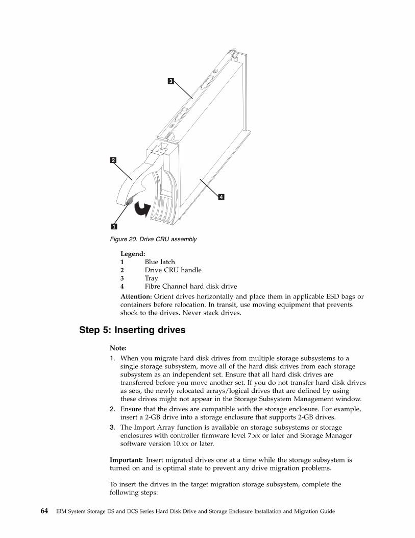
Legend:1 Blue latch2 Drive CRU handle3 Tray4 Fibre Channel hard disk driveAttention: Orient drives horizontally and place them in applicable ESD bags orcontainers before relocation. In transit, use moving equipment that preventsshock to the drives. Never stack drives.
Step 5: Inserting drives
Note:
1. When you migrate hard disk drives from multiple storage subsystems to asingle storage subsystem, move all of the hard disk drives from each storagesubsystem as an independent set. Ensure that all hard disk drives aretransferred before you move another set. If you do not transfer hard disk drivesas sets, the newly relocated arrays/logical drives that are defined by usingthese drives might not appear in the Storage Subsystem Management window.
2. Ensure that the drives are compatible with the storage enclosure. For example,insert a 2-GB drive into a storage enclosure that supports 2-GB drives.
3. The Import Array function is available on storage subsystems or storageenclosures with controller firmware level 7.xx or later and Storage Managersoftware version 10.xx or later.
Important: Insert migrated drives one at a time while the storage subsystem isturned on and is optimal state to prevent any drive migration problems.
To insert the drives in the target migration storage subsystem, complete thefollowing steps:
Figure 20. Drive CRU assembly
64 IBM System Storage DS and DCS Series Hard Disk Drive and Storage Enclosure Installation and Migration Guide

1. While the destination storage subsystem is turned on, insert the migratingdrives into an empty drive bay one at a time. Wait (up to 5 minutes) until theinserted drive is fully spun up and displayed in the Storage SubsystemManagement window before you insert the next drive.v On storage subsystems with controller firmware level 6.xx.xx.xx or earlier, as
the storage subsystem recognizes the drives, the array and logical driveinformation is shown on the Logical/Physical view of the Storage SubsystemManagement window. The storage subsystem represents arrays in offlinestate until it recognizes that you insert all of the drives that make up anarray.
v On storage subsystems with controller firmware level 7.10 or later, arraysappear in Contingent state (with an arrow icon) until all of the drives in thearray are inserted. The array appears in Exported - ready to import state.
2. If the migrated drives are FDE drives and were configured as part of securedarray, use the saved security key to unlock the drives. Without this security key,the controllers cannot unlock the drives to retrieve the array configuration dataand data on the drives. Therefore, you cannot import any array/logical driveconfiguration from the drives or access data in the drives.
3. Depending on the controller firmware and Storage Manager software versionsof your system, complete the following steps:v With controller firmware and Storage Manager software before controller
firmware level 7.xx and Storage Manager software version 10.xx, after youmigrate all of the drives, manually change the state of the arrays and logicaldrives that are involved from Optimal state to Online state if it does notchange automatically. To do so, right-click the array name in the StorageSubsystem Management window and click Place -> Online.
v With controller firmware level 7.xx or later and Storage Manager softwareversion 10.xx or later, after you migrate all of the drives, import the array:a. Right-click on the name of the array that you want to import in the
Storage Subsystem Management window.b. Select Advanced -> Import from the pull-down menu.c. In the confirmation window, click OK.d. Click Import.e. In the Import Array window, type yes and click OK.
After a successful import, the message Array was imported successfullyis displayed in the dialog box.
f. Click Close.
Note: The DS3000 storage subsystem supports these array functions thoughthe SMcli interface. See the Storage Manager online help for the SMclicommand syntax.
4. If any of the following conditions occur, contact IBM support for assistance:
v The Empty Drive Bay icon ( ) is displayed for the drive bay into whichyou inserted the migrating drive.
v The Failed Unconfigured Drive icon ( ) or the Failed Configured Drive
icon ( ) is displayed for the drive bay into which you inserted themigrating drive.
v Array configuration data on the drives that you added is incomplete.
Chapter 2. Adding or migrating hard disk drives 65

v You cannot bring the array online (controller firmware 6.xx.xx.xx and lower)or import the array (controller firmware 7.xx.xx.xx or later).
Attention:
Attention: Do not initialize a hard disk drive that you want to keep (byright-clicking its icon and selecting Initialize from the menu) if it containsconfiguration or user data. Initializing any drives in a defined array causes allhard disk drives that are known to make up that array to return to theUnconfigured Capacity storage pool, deleting their array definitions from theDS4000 storage subsystem configuration. The user data on such drives is lost.When the arrays are online, they are ready to for you to configure and map tohost servers. You might also then re-create FlashCopy images of the logicaldrives.
5. Use the DS Storage Manager program to view the storage partitioningdefinitions and make any necessary corrections.
Note: The source storage subsystem might indicate that the logical drives aremissing. To remove the missing logical drives, right-click each entry and selectDelete from the menu.
Migrating arrays within the same storage subsystemImportant
1. Ensure that your controller firmware is at or above the level shown in Table 2on page 9. Do not rearrange more than one array at a time.
2. Unmount the file systems to flush I/O from the server cache to disks.
Note:
a. In a Microsoft Windows environment, remove the drive letter or the mountpoints of the mapped LUNs instead of unmounting the file systems.
b. See the documentation for your operating system for detailed informationabout the unmount procedure.
3. Export Array and Import Array functions are available on storage subsystemsor storage enclosures with controller firmware level 7.xx or later and StorageManager software version 10.xx or later. The DS3000 storage subsystemsupports these array functions though the SMcli interface. See the StorageManager online help for the SMcli command syntax.
Note: Because disk pool does not support exporting and importing functions,this functionality is not applicable to drives in disk pools.
Using the configuration data on existing drives, you can redistribute the drivesthat make up a RAID array across a storage subsystem to which you might beadding storage enclosures. Figure 21 on page 67 illustrates a storage array that isdistributed across three drives on a single storage device before and afterreordering. When you redistribute each drive to a different position in the samestorage enclosure, which is a best practice, the array is automatically redistributed.
66 IBM System Storage DS and DCS Series Hard Disk Drive and Storage Enclosure Installation and Migration Guide

Figure 22 illustrates a storage array that is distributed across three drives on asingle storage device before reordering across two storage devices. When thedrives are redistributed across an additional storage enclosure in the storagesubsystem, which is a best practice, the array is automatically redistributed.
Figure 23 on page 68 illustrates two arrays that are distributed across five drivesand two storage enclosures before and after reordering the same drives acrossother drive bays in the same two storage enclosures.
Note: If the installed controller firmware level is 6.xx.xx.xx or earlier, before youattempt to remove and reinsert any of the drives from either enclosure, place thearray into offline state by using the DS Storage Manager Client and completelyremove all of the drives of both arrays from both storage enclosures. Wait for DSStorage Manager to display the arrays/logical drives as missing and the drive baysas empty. After you insert the drives that are associated with the first array, waituntil that array comes online in a DS Storage Manager Subsystem Managementwindow before you insert the drives that are associated with the second array.
If the installed controller firmware is 7.xx.xx.xx or later, before you attempt toremove and reinsert drives from either enclosures, export the arrays by using theDS Storage Manager Client. After the array is exported, remove the drives andreinsert them in the drive bays in the same storage subsystem. Then, use the DSStorage Manager Client to import the arrays. Note the following information:v Using the Export function is equivalent to placing the array in Offline state. See
“Step 3: Placing drives offline” on page 62 for details on exporting an array.v When you install the first drive in its new location within the storage subsystem,
the Array icon appears with an arrow but does not change to Online stateautomatically. You must use the Import function to place the array in Onlinestate.
1 2 3 4 5 6
Before After
Empty slot
Drive associated with array
Figure 21. Best practice for reordering a defined array by using empty bays in one storageenclosure
1 2 3 1 2
3
Before After
Empty slot
Drive associated with array
Figure 22. Best practice for reordering a defined array by using empty bays in two storageenclosures
Chapter 2. Adding or migrating hard disk drives 67
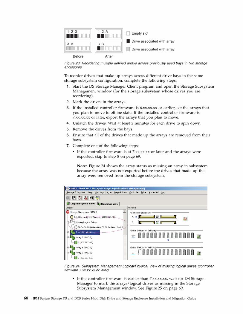
To reorder drives that make up arrays across different drive bays in the samestorage subsystem configuration, complete the following steps:1. Start the DS Storage Manager Client program and open the Storage Subsystem
Management window (for the storage subsystem whose drives you arereordering).
2. Mark the drives in the arrays.3. If the installed controller firmware is 6.xx.xx.xx or earlier, set the arrays that
you plan to move to offline state. If the installed controller firmware is7.xx.xx.xx or later, export the arrays that you plan to move.
4. Unlatch the drives. Wait at least 2 minutes for each drive to spin down.5. Remove the drives from the bays.6. Ensure that all of the drives that made up the arrays are removed from their
bays.7. Complete one of the following steps:v If the controller firmware is at 7.xx.xx.xx or later and the arrays were
exported, skip to step 8 on page 69.
Note: Figure 24 shows the array status as missing an array in subsystembecause the array was not exported before the drives that made up thearray were removed from the storage subsystem.
v If the controller firmware is earlier than 7.xx.xx.xx, wait for DS StorageManager to mark the arrays/logical drives as missing in the StorageSubsystem Management window. See Figure 25 on page 69.
1 2 3 1 2 A
3 BA B
Before After
Empty slot
Drive associated with array
Drive associated with array
Figure 23. Reordering multiple defined arrays across previously used bays in two storageenclosures
Figure 24. Subsystem Management Logical/Physical View of missing logical drives (controllerfirmware 7.xx.xx.xx or later)
68 IBM System Storage DS and DCS Series Hard Disk Drive and Storage Enclosure Installation and Migration Guide
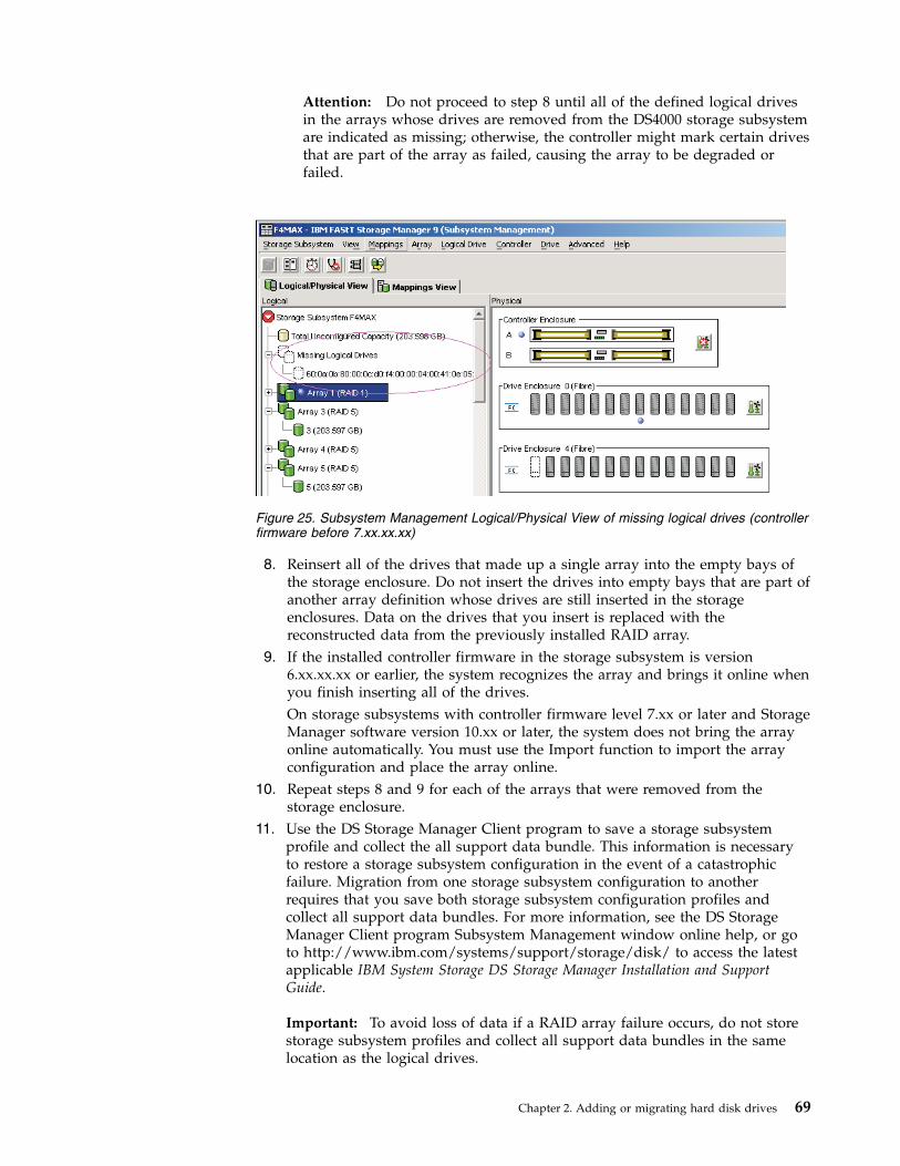
Attention: Do not proceed to step 8 until all of the defined logical drivesin the arrays whose drives are removed from the DS4000 storage subsystemare indicated as missing; otherwise, the controller might mark certain drivesthat are part of the array as failed, causing the array to be degraded orfailed.
8. Reinsert all of the drives that made up a single array into the empty bays ofthe storage enclosure. Do not insert the drives into empty bays that are part ofanother array definition whose drives are still inserted in the storageenclosures. Data on the drives that you insert is replaced with thereconstructed data from the previously installed RAID array.
9. If the installed controller firmware in the storage subsystem is version6.xx.xx.xx or earlier, the system recognizes the array and brings it online whenyou finish inserting all of the drives.On storage subsystems with controller firmware level 7.xx or later and StorageManager software version 10.xx or later, the system does not bring the arrayonline automatically. You must use the Import function to import the arrayconfiguration and place the array online.
10. Repeat steps 8 and 9 for each of the arrays that were removed from thestorage enclosure.
11. Use the DS Storage Manager Client program to save a storage subsystemprofile and collect the all support data bundle. This information is necessaryto restore a storage subsystem configuration in the event of a catastrophicfailure. Migration from one storage subsystem configuration to anotherrequires that you save both storage subsystem configuration profiles andcollect all support data bundles. For more information, see the DS StorageManager Client program Subsystem Management window online help, or goto http://www.ibm.com/systems/support/storage/disk/ to access the latestapplicable IBM System Storage DS Storage Manager Installation and SupportGuide.
Important: To avoid loss of data if a RAID array failure occurs, do not storestorage subsystem profiles and collect all support data bundles in the samelocation as the logical drives.
Figure 25. Subsystem Management Logical/Physical View of missing logical drives (controllerfirmware before 7.xx.xx.xx)
Chapter 2. Adding or migrating hard disk drives 69

Note: Do not reinsert drives from multiple arrays in random order into thestorage enclosures.
Using the drive migration disable script to add new drives
Attention:
1. You can use this procedure to add new drives, if the installed controllerfirmware version is 6.xx.xx.xx and earlier and the DS Storage Manager InitializeDrive function does not initialize the drives. However, use this procedure onlyas a last resort. If possible, follow the procedure in “Adding new hard diskdrives” on page 58.
2. Do not use this procedure if the installed controller firmware is version7.xx.xx.xx or later.
3. To avoid loss of data, follow the procedures in this section exactly.
Do not use these procedures to migrate drives with existing configuration data.Otherwise, the data in the migrated drives is lost. In addition, ensure that “Step 3:Re-enabling the drive migration settings” on page 71 is performed successfully ifyou do perform procedure in this section. If not, configuration data in the drives inthe storage subsystems is deleted when the storage subsystem is power-cycled.
Step 1: Disabling the drive migration settings
Important: Review the information in “Introduction” on page ix and perform theprerequisites that are described in Chapter 1, “Prerequisites to adding capacity andhard disk drive migration,” on page 1 before you perform the activities that aredescribed in this section.
To remove any configuration data that the drives might contain, complete thefollowing steps:1. Open the Storage Manager Client Enterprise Management window.2. Right-click the name of the DS4000 storage subsystem to which you intend to
add drives and click Execute Script.3. Click File -> Load Script.4. Locate and select the file named DisableDriveMigration.scr and click OK. The
DisableDriveMigration.scr file is normally in the Scripts directory of the IBMDS Storage Manager Installation DVD. Use this file to reset the setting of theDS4000 storage subsystem to ignore configuration data that might be on newlydiscovered hard disk drives. Table 21 on page 73 provides a listing of theDisableDriveMigration.scr file.
5. Click Tools -> Verify and Execute to run the script.6. When the script completes execution, reset both DS4000 controllers to enable
the DS4000 drive migration setting.If you used the DisableDriveMigration.scr script that is associated with thisdocument and described in Table 20 on page 72, it is not necessary for you toperform this step because the last two commands in that script fileautomatically reset the controllers.To reset the controllers, open the Storage Subsystem Management window andsequentially (one at a time) reset each controller by clicking Advanced -> ResetController. Then, follow the instructions in the Reset Controller window whenit opens.
70 IBM System Storage DS and DCS Series Hard Disk Drive and Storage Enclosure Installation and Migration Guide

Step 2: Inserting drivesTo insert the hard disk drives, complete the following steps:1. Insert drives as pairs (two at a time) into the empty drive bays.2. Wait (up to 5 minutes) until each drive pair fully spins up and appears in the
DS Storage Subsystem Management window before you insert the next drivepair.
Step 3: Re-enabling the drive migration settingsPerform this activity to re-enable the drive migration settings if you performed“Step 1: Disabling the drive migration settings” on page 70 to disable DS4000storage subsystem drive migration settings. If you do not, when you remove ahard disk drive from the storage subsystem, the configuration data is cleared.When the storage subsystem next recognizes such a hard disk drive, it is identifiedas unconfigured.
Attention: To prevent data loss, set the storage subsystem drive migration toEnable after you complete the hard disk drive addition process.
To re-enable the drive migration settings, complete the following steps:1. Open the Storage Manager Client Enterprise Management window.2. Right-click the name of the storage subsystem to which you want to add
drives, and click Execute Script.3. Click File -> Load Script.4. Select the file named EnableDriveMigration.scr and click OK. The
EnableDriveMigration.scr file is normally in the Scripts directory of the IBMDS Storage Manager Installation DVD. Use this file to reset the setting of theDS4000 storage subsystem to check for configuration data that might be onnewly discovered hard disk drives. Table 20 on page 72 provides a listing of theEnableDriveMigration.scr file.
5. Click Tools -> Verify and Execute to run the script.6. When the script completes execution, reset both controllers to enable the drive
migration setting.
If you use the EnableDriveMigration.scr script that is associated with thisdocument and described in Table 20 on page 72, it is not necessary for you toperform this step because the last two commands in that script file automaticallyreset the controllers.
To reset the controllers, open the Storage Subsystem Management window andsequentially (one at a time) reset each controller by clicking Advanced -> ResetController, and then following the instructions in the Reset Controller windowwhen it opens.
The following figures list the EnableDriveMigration.scr andDisableDriveMigration.scr files.
Chapter 2. Adding or migrating hard disk drives 71
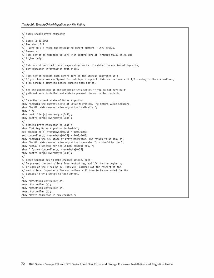
Table 20. EnableDriveMigration.scr file listing
// Name: Enable Drive Migration//// Date: 11-20-2005// Revision: 1.4// Version 1.4 fixed the misleading on/off comment - CMVC 296330.// Comments:// This script is intended to work with controllers at Firmware 05.30.xx.xx and// higher only.//// This script returned the storage subsystem to it’s default operation of importing// configuration informration from disks.//// This script reboots both controllers in the storage subsystem unit.// If your hosts are configured for multi-path support, this can be done with I/O running to the controllers,// else schedule downtime before running this script.//// See the directions at the bottom of this script if you do not have multi// path software installed and wish to prevent the controller restarts//// Show the current state of Drive Migrationshow "Showing the current state of Drive Migration. The return value should";show "be 82, which means drive migration is disable.";show " ";show controller[a] nvsrambyte[0x35];show controller[b] nvsrambyte[0x35];//// Setting Drive Migration to Enableshow "Setting Drive Migration to Enable";set controller[a] nvsrambyte[0x35] = 0x02,0x00;set controller[b] nvsrambyte[0x35] = 0x02,0x00;show "Showing the new state of Drive Migration. The return value should";show "be 80, which means drive migration is enable. This should be the ";show "default setting for the DS4000 controllers. ";show " ";show controller[a] nvsrambyte[0x35];show controller[b] nvsrambyte[0x35];//// Reset Controllers to make changes active. Note:// To prevent the controllers from restarting, add ’//’ to the beginning// of each of the lines below. This will comment out the restart of the// controllers. Important: The controllers will have to be restarted for the// changes in this script to take effect.//show "Resetting controller A";reset Controller [a];show "Resetting controller B";reset Controller [b];show "Drive Migration is now enabled.";
72 IBM System Storage DS and DCS Series Hard Disk Drive and Storage Enclosure Installation and Migration Guide

Table 21. DisableDriveMigration.scr file listing
// Name: Disable Drive Migration// Date: 11-20-2005// Revision: 1.4// Version 1.4 fixed the misleading on/off comment - CMVC 296330.// Comments:// This script is intended to work with controllers at Firmware 05.30.xx.xx// and higher only.// This script allows the addition of disk drives while the system is running// and by clearing the configuration of any drives as unused capacity// regardless of past configuration of these drives.//// Attention: This setting should not be left active after the new disks// have been added to the subsystem. Leaving this setting active could// cause the configuration for the DS4000 to be lost if the DS4000// is power cycled. Please run the EnableDriveMigration.scr after all of// the disks are added. IN ADDITION, DO NOT USE THIS SCRIPT IF YOU WANT// TO PRESERVE THE DATA IN THE DRIVES THAT YOU ARE PLANNING TO ADD INTO// THE EXISTING DS4000 STORAGE SUBSYSTEM CONFIGURATION. Please refer to// the DS4000 adding capacity and drive migration publication for more// information.// This script will reboot both controllers in the storage subsystem unit. If your// hosts are configured for multi-path support, this can be done with I/O// running to the controllers. If your hosts are not configured for// redundant access you much schedule downtime before running this script.//// Show the current state of Drive Migrationshow "Showing the current state of Drive Migration. The return value should";show "be 80, which means drive migration is enable. This should be the ";show "default setting for the DS4000 controllers. ";show " ";show controller[a] nvsrambyte[0x35];show controller[b] nvsrambyte[0x35];//// Setting Drive Migration to Disableshow "Setting Drive Migration to Disable";set controller[a] nvsrambyte[0x35] = 0x02,0x02;set controller[b] nvsrambyte[0x35] = 0x02,0x02;show "Showing the new state of Drive Migration. The return value should be";show "82, which means drive migration is disable. Please run the enableDrive";show "Migration.scr script as soon as you complete the inserting of ";show "new drives into the DS4000 storage subsystem slots.";show " ";show controller[a] nvsrambyte[0x35];show controller[b] nvsrambyte[0x35];//// Reset Controllers to make changes active// To prevent the controllers from restarting, add ’//’ to the beginning of each// of the lines below. This will comment out the restart of the controllers// Important: The controllers will have to be restarted for the changes// in this script to take effect.show "Resetting controller A";reset Controller [a];show "Resetting controller B";reset Controller [b];//show "Drive Migration is now disabled. Add the new drives to the subsystem,";show "then execute the EnableDriveMigrationScript.scr to re-enable drive ";show "migration.";
Chapter 2. Adding or migrating hard disk drives 73

74 IBM System Storage DS and DCS Series Hard Disk Drive and Storage Enclosure Installation and Migration Guide

Chapter 3. Adding or migrating storage enclosures
This chapter describes the procedure to add storage enclosures in a storagesubsystem. It also describes the procedure to migrate storage enclosures from anexisting storage subsystem to another working optimal storage subsystem. If thedestination storage subsystem is a working configuration, follow the procedure inthis chapter to move one or all of the storage enclosures from another storagesubsystem configuration into it. The storage subsystem is in Working state whenthe storage subsystem controllers successfully start with at least two drives in thedrive channel.
Note: To migrate the drives in the integrated drive-controller enclosure to anotherstorage subsystem configuration without an integrated drive-controller enclosure,you must purchase a storage enclosure for these drives.
Important: Observe proper ESD procedures when you handle electronicequipment. For more information, see “Handling static-sensitive devices” on page58.Attention:
Make additions to the storage subsystem only while the power is turned on andthe storage subsystem is in Optimal state. For more information, see “Bringingstorage subsystems and drive loops into optimal state” on page 21. You cancomplete this process while the storage subsystem is receiving I/O from the hostserver; however, because the drive loops are interrupted momentarily during theaddition process, schedule the addition to occur during periods of low I/Obetween the storage subsystems and host servers.
ConsiderationsThe following notes describe information that you must consider when you add ahard disk drive to a controller or a storage enclosure:v Updated readme files contain important configuration and procedural
information that supersede information in this document. Always check thereadme file before you perform any procedure or activity that is described inthis document. To access the most recent readme file, see “Finding StorageManager software, controller firmware, and readme files” on page 147.
v Never alter the physical configuration of a storage subsystem while it is turnedoff unless you are instructed to do so as part of a storage subsystemconfiguration procedure. Specifically, never attach storage components to orremove storage components from a configured storage subsystem while it isturned off.
v Every storage subsystem model has unique storage enclosure cabling rules. Seethe Installation, User’s and Maintenance Guide for your storage subsystem forinformation about the storage enclosure cabling rules. You must follow thecabling rules to maintain proper storage subsystem operation.
v When you migrate hard disk drives from multiple storage subsystems to a singlestorage subsystem, move all of the hard disk drives from each storage subsystemas an independent set. Before you move the next set of hard disk drives, ensurethat all the hard disk drives from the previous set are transferred. If you do nottransfer hard disk drives as sets, the newly relocated arrays/logical drives mightnot appear in the Storage Subsystem Management window.
© Copyright IBM Corp. 2008, 2013 75
v Before you migrate hard disk drives, perform the following steps to establishdrive model compatibility:1. Check the drive CRU form factor options.2. If the form factors are the same, check to determine whether the subsystem
supports the drive. If the form factors are not the same, there are noreplacement parts such as bezels and drive trays. For more information, seethe announcement letter and the Installation, Users, and Maintenance Guide foryour storage subsystem, and your IBM marketing representative orauthorized reseller.
3. Ensure that the drive can operate at the storage subsystem driveloop/channel Fibre Channel or SAS speed. For more information, see“Verifying hard disk drive model compatibility” on page 17.
v Not all combinations of the supported storage enclosures are supported asstorage enclosures intermixed behind storage subsystems.
v Do not mix SATA and Fibre Channel drives or enclosures together in the samedrive loop unless you meet the Fibre Channel/SATA intermix requirements. See“Intermixing storage enclosures” on page 21 for that information.
v Check for drive compatibility in a storage subsystem configuration before youinsert a drive in an empty drive slot. For example, do not install SATA drives inEXP700 or EXP710 Fibre Channel drive storage enclosures. Do not install FibreChannel drives in EXP100 SATA and EXP420 storage enclosures. EXP520,EXP810, and EXP5000 storage enclosures can accept either Fibre Channel orSATA Enhanced Disk Drive Modules (E-DDMs). The EXP420 storage enclosuresupports SATA E-DDMs only.
v Do not attach more than four storage enclosures behind a DS4200 Express,DS4700 Express, DS4800, DS5000, or DS5020 storage subsystem drive channelport. For more information, see the Installation, User's, and Maintenance Guide foryour storage subsystem.
v You can intermix EXP5000 and EXP5060 storage enclosures up to a maximum of448 drives. To support 480 drives, you must have all EXP5060 storage enclosuresand have feature 7372 to attach eight EXP5060 storage enclosures.
v Always connect the storage subsystem controller drive channel port to either theleft or right EXP395, EXP420, EXP520, or EXP810, EXP5000, or EXP5060 storageenclosure ESM drive port labeled 1B.
v Always connect the storage subsystem controller drive channel port to either theleft or right EXP3000, EXP3512, or EXP3524 ESM drive port labeled IN (SAS Inconnector) or to the top or bottom DCS3700 storage expansion enclosure ESMdrive port.
v When you intermix the storage enclosures in a redundant drive loop/channelpair behind a DS4000 storage subsystem, always group the storage enclosures bytype; for example, group the EXP100 storage enclosures together, and group theEXP700 storage enclosures together. You can group the EXP710 and EXP810storage enclosures together. The EXP710 and EXP810 storage enclosures areconsidered Switched-ESM types of storage enclosures even though they havedifferent machine types and models.Although there are no restrictions against cabling EXP710 and EXP810 storageenclosures together, for ease of future maintenance and to aid in troubleshooting,group the storage enclosures by type in a DS4000 storage subsystem redundantdrive loop/channel pair.
v Ensure that the enclosure IDs of each storage enclosure in a redundant driveloop/channel pair behind a storage subsystem have unique values in the singledigit (x1) position.
76 IBM System Storage DS and DCS Series Hard Disk Drive and Storage Enclosure Installation and Migration Guide

v The EXP395, EXP520, and EXP5000 storage enclosures support 4-Gbps drivesonly.
v For information about the EXP5000 and EXP5060 storage enclosures, see note 2on page 24.
The following procedure combines the steps to add storage enclosures that containnew drives to a storage subsystem configuration with the steps to migrate storageenclosures. There are indicators in the steps that are specific to either adding ormigrating enclosure tasks. If you are migrating storage enclosures, do not performthe steps that are indicated as being only for adding storage enclosures:performing steps for adding storage enclosures might cause the deletion of thelogical drive configuration in the migrated hard disk drives.
Step 1: Preliminary activitiesBefore you add or migrate storage enclosures, complete the following steps:1. Ensure that the power to the storage subsystem is turned on and the storage
subsystem is in Optimal state.If this is a migrating enclosure task, also ensure that the subsystem in whichthe enclosures are to be migrated is turned on and is in Optimal state. For moreinformation, see the DS3000 Problem Determination Guide, the Recovery guru forDS3500, DCS3700 (DCS3700 and DCS3700 with Performance ModuleControllers), DCS3860, DS4000, and DS5000 storage subsystems, or “Bringingstorage subsystems and drive loops into optimal state” on page 21. You canperform this procedure while the storage subsystem is processing I/O from orto the host server; however, because the drive loops are interruptedmomentarily during the addition process, schedule any additions to occurduring time periods of low I/O between the storage subsystem and hostservers.
Note: Although there are no restrictions against cabling EXP100 storageenclosures with EXP700, or EXP710 storage enclosures with EXP810 storageenclosures, for ease of future maintenance and to aid in troubleshooting, groupthe storage enclosures by type in a DS4000 storage subsystem redundant driveloop/channel pair.Review the readme file and the IBM System Storage DS Storage ManagerInstallation and Support Guide that is associated with the operating-systemenvironment of the host servers that connect to the storage subsystem for anyadditional restrictions or required preparation tasks that are specific to youroperating-system environment. To access the latest IBM System Storage DSStorage Manager installation and support guides, go to http://www.ibm.com/systems/support/storage/disk/.
2. Perform a collect all support data bundles and save the storage subsystemconfiguration.
3. Ensure that the storage subsystem supports the storage enclosures that you aretrying to add or migrate.
4. In the drive enclosure migration situation, verify the controller firmware levelof both the source and target storage subsystems. Upgrade both source andtarget storage subsystems to the same controller firmware if possible.
5. If the storage enclosure that is to be migrated is not the same type as theexisting storage enclosures (some or all), see “Intermixing storage enclosures”on page 21 for intermix information.
Chapter 3. Adding or migrating storage enclosures 77

Note: You must group like storage enclosure types in adjacent positions on theFibre Channel loop when they are intermixed in a DS4000 storage subsystemredundant drive loop configuration.
6. If you are adding new enclosures with new drives, proceed with the steps in“Adding new storage enclosures with new hard disk drives”; otherwise,proceed to the steps in “Migrating storage enclosures with hard disk drives thathave defined logical drive configurations” on page 79.
Adding new storage enclosures with new hard disk drivesTo add new storage enclosures with new hard disk drives, complete the followingsteps:1. Unpack and mount any additional storage enclosures in the rack by using the
mounting hardware that is supplied with each storage enclosure.Important: Do not fully insert hard disk drives into the enclosures at this time.Keep them unlatched and no less than 1.27 cm (0.5 in.) away from their fullinsertion points in the drive bays.
2. Set the enclosure ID of the additional storage enclosures with Fibre Channeldrive ports that have a mechanical enclosure ID switch.Each enclosure in the storage subsystem configuration must have a uniqueenclosure ID. In addition, the IDs of enclosures (including the storagesubsystem with internal drive bays) that are connected together in the sameredundant drive loop/channel pair must each have a unique rightmost digit.For example, 01, 02, 03, 04 or 11, 12, 13, 14 are the correct IDs of the enclosures,including the subsystems with internal drives that are connected together in adrive loop/channel, whereas 01, 11, 21, 31 or 11, 11, 22, 33 are not the correctIDs of the enclosures that are connected together in a drive loop/channel pair(including the subsystems with internal drives) because the rightmost digits inthe enclosure IDs are not unique (01, 11, 21, 31) or the enclosure IDs are notunique (11, 11, 22, 33).The EXP500 storage enclosure has an enclosure ID switch on each ESM canister.Set each enclosure ID switch to the same unique number as the drive loop.EXP100, EXP700, and EXP710 storage enclosures have one enclosure ID switchbetween the power supplies. The EXP395, EXP420, EXP520, EXP810, EXP5000,EXP5060, and DCS3700 storage expansion enclosures have a display that showsthe enclosure ID. The controller firmware automatically sets the enclosure ID;however, you can change the enclosure ID through the DS Storage ManagerClient program.For more information, see the documentation that comes with your storageenclosure. Figure 26 on page 79 illustrates the location of enclosure ID switcheson the EXP100, EXP500, EXP700, EXP710, and EXP420/EXP520/EXP810/EXP5000 storage enclosures.
78 IBM System Storage DS and DCS Series Hard Disk Drive and Storage Enclosure Installation and Migration Guide

If the storage subsystem to which the storage enclosure attaches is a DS3000,DS3500, DCS3700, DCS3700 with Performance Module Controllers, DCS3860,DS3950, DS4100, DS4200, DS4300, DS4700 Express, or DS5020 storagesubsystem, the enclosure IDs of additional storage enclosures must be uniqueto the storage subsystem. The enclosure ID of DS3500, DCS3700, DCS3700 withPerformance Module Controllers, DS4100, and DS4300 storage subsystems isnormally set to 00 at the factory. The enclosure ID of the DS3000, DS3950,DS4200, DS4700 Express, and DS5020 storage subsystems is normally set to 85at the factory.
3. If necessary, ensure that the storage enclosure speed switch is set to the correctdrive loop speed, which is the highest speed at which all enclosures in thedrive loop/channel can operate. Not all storage enclosures have an enclosurespeed switch. For more information, see the storage enclosure documentation.For example, if there is a mix of drive enclosures that are Fibre Channel 4 Gbpscapable and Fibre Channel 2 Gbps capable in the same drive loop/channel, allof the enclosures must have the speed switch set at the highest speed that allenclosures can operate, which is Fibre Channel 2-Gbps speed.
Note: If a Fibre Channel enclosure speed switch was originally set to 1 Gbps,do not automatically set it to 2 Gbps unless you are sure that each FibreChannel hard disk drive that it contains is capable of 2-Gbps operation. Ensurethat you installed the latest firmware to enable hard disk drive operation in a2-Gbps Fibre Channel environment. Similarly, do not automatically change thesettings from 2 Gbps to 4 Gbps unless you are sure that the installed drives arecapable of a 4-Gbps operation. Do not automatically move up to higher speedunless the installed disk drives can operate at a higher speed.
4. Proceed to “Step 6: Cabling, turning on, and verifying storage enclosureoperation” on page 84. Do not perform Activities 3–5.
Migrating storage enclosures with hard disk drives that havedefined logical drive configurations
Before you begin, review the “Drive migration limitations” on page 15 section.Drives with disk pools cannot be migrated from one subsystem to another. The
Enclosure Fibre Channelspeed switch Enclosure ID
switch
FaStT EXP500Enclosure IDswitch
DS4000 EXP700DS4000 EXP100
DS4000 EXP710Enclosure IDswitch
Enclosure IDdisplay
DS4000 EXP810
dg1gr0
65
Figure 26. EXP100, EXP500, EXP700, EXP710, EXP395/EXP420/EXP520/EXP810/EXP5000storage enclosure ID and speed switches
Chapter 3. Adding or migrating storage enclosures 79

data in the disk pool must be backed up to a tape or to drives that are part oftraditional arrays. Then, the data is restored to newly created disk pools in anotherstorage subsystem.
To migrate storage enclosures with hard disk drives that have defined logical driveconfigurations, complete the following steps.1. Ensure that controller firmware and NVSRAM in both the target migration
storage subsystem and the storage subsystem that contains the enclosures thatare to be migrated are at the levels in Table 2 on page 9.
2. Ensure that the firmware of the ESMs in the storage enclosures that you planto migrate are at the levels in Table 3 on page 12.
3. Ensure that the firmware of the ESMs in the storage enclosures that areattached to the target migration storage subsystem is at the levels in Table 3on page 12.
4. If you migrate storage enclosures from a lower Fibre Channel environment toa higher Fibre Channel environment (for example, moving from 1 Gbps to 2Gbps or from 2 Gbps to 4 Gbps), verify that each of the Fibre Channel harddisk drives that you plan to migrate are capable of higher Fibre Channelspeed operation and that you installed the latest firmware, if required.Data on drives migrate with those drives when the drives are installed onanother storage subsystem. For a successful migration, perform steps 5, 6, 7and 8 that follow.
5. Delete the storage partitioning mappings of the logical drives.6. Ensure that all of the IDs of the storage enclosures in the redundant drive
loop/channel have unique single digit (x1) values.7. In addition to array configuration information, any storage partitioning
configuration data on drives migrate with those drives when they are installedon another storage subsystem. For this reason, take the following precautionsto facilitate the migration process and prevent problems in storagepartitioning configuration data migration:a. If a storage partitioning premium feature is enabled on both the original
and destination storage subsystems, ensure that the defined host ports,hosts, and host group names are unique to each storage subsystem that isinvolved in the migration.
b. If you must use identical names on both storage subsystems, make thenames unique before you perform the drive migration. If necessary,customize the storage partitioning information about the storagesubsystem to which you migrated the drives after you complete themigration.
8. Delete any FlashCopy images of logical drives that are defined in the harddisk drives.
9. Remove any remote mirror relationships that involve the logical drives thatare defined on the drives that you plan to migrate.
10. Proceed to “Step 2: Preparing and backing up the drives.”
Step 2: Preparing and backing up the drivesTo prepare and back up the drives, complete the following steps.
Note: The following procedure is for migrating enclosures with drives that havedefined arrays/logical drives only. Do not perform this procedure if you areadding enclosures with new drives or drives that contain unneeded data.
80 IBM System Storage DS and DCS Series Hard Disk Drive and Storage Enclosure Installation and Migration Guide

1. If the arrays and logical drives that are involved are not in Optimal state,perform the steps that are necessary to bring these arrays and logical drives toOptimal state before you attempt migration. Use the Recovery Guru function inthe Storage Subsystem Management window of the DS Storage Manager Clientprogram. For more information, “Bringing storage subsystems and drive loopsinto optimal state” on page 21.
2. If the drive enclosures that you plan to migrate are not in Optimal state,perform the steps that are necessary to bring them to Optimal state before youattempt migration. Use the Recovery Guru function in the Storage SubsystemManagement window of the DS Storage Manager Client program. For moreinformation, see “Bringing storage subsystems and drive loops into optimalstate” on page 21.
3. Perform a backup of the logical drives that are defined in the storageenclosures.
4. Monitor the storage subsystem event log for any errors in the drive loop or itscomponents for several days before you migrate storage enclosures.
5. Stop all programs, services, or processes in the host servers that access thelogical drives that are defined in the migrated hard disk drives. ensure thatthere are not any running background programs, services, or processes thatwrite data to the logical drives. (For example, Microsoft MSCS serviceperiodically writes to the “Quorum” disk.)
6. Unmount the file systems to flush I/O from the server cache to disks.
Note:
a. In a Microsoft Windows environment, remove the drive letter or the mountpoints of the mapped LUNs instead of unmounting the file systems.
b. See the documentation for your operating system for detailed informationabout the unmount procedure.
7. Save the storage subsystem profile and storage subsystem configuration, andcollect all support data bundles of the target storage subsystem in a locationother than the logical drives that you plan to migrate.
8. Place the arrays that are defined in the storage enclosures that you plan tomigrate in Offline state. The method that you use to place an array in Offlinestate varies according to the controller firmware and Storage Manager softwareversions:v If the controller firmware level is earlier than 7.xx and the Storage Manager
software version is 10.xx, right-click the name of the array in the StorageSubsystem Management window and click Place -> Offline.
v If the controller firmware level is 7.xx or later and the Storage Managersoftware version is 10.xx or later, use the Export Array feature. See “Step 3:Placing drives offline” on page 62 for details.
Note: The DS3000 storage subsystem supports these array functions though theSMcli interface. See the Storage Manager online help for the SMcli commandsyntax.
9. If the migrated drives are FDE drives and were configured as part of a securedarray, save the security key to unlock the drives after you install them in a newstorage subsystem. Without this key, the controllers cannot unlock the drives toperform read and write operations.
Step 3: Shutting down and moving the storage enclosuresTo shut down and move the storage enclosure, complete the following steps.
Chapter 3. Adding or migrating storage enclosures 81

Note: The following procedure is for migrating enclosures with drives that havedefined arrays/logical drives only. Do not perform this procedure if you areadding enclosures with new drives or drives that contain unneeded data.1. Because removing a storage enclosure from a storage subsystem disrupts the
drive loops, shut down the storage subsystem while you remove the storageenclosures for migration to another storage subsystem. If you cannot shutdown the storage subsystem, reconfigure only one drive loop, making sure thatthe drive loop that you modify is connected correctly and in Optimal statebefore you attempt to reconfigure the other drive loop. For more information,see “Bringing storage subsystems and drive loops into optimal state” on page21.Take this precaution to prevent the arrays from being inadvertently failed bythe storage subsystem controllers because two or more drives in the arrayscannot be reached through either drive loop in the redundant drive loop pair.Complete the following steps to verify that the drive loops are in Optimal state:a. Physically trace the actual cable connections to ensure that connections are
properly modified and that the cable connectors are firmly inserted into theSFPs or GBICs.
b. Ensure that the following LEDs are not lit or flashing in the modified driveloop:v ESM faultv Port bypassv ID conflict
c. Ensure that the controller drive loop LED remains lit. If the controller driveloop LED is turned off, there are problems in the drive loop, and the loopinitialization primitives (LIPs) are generated by the storage subsystemcontroller.
d. In the DS Storage Manager Client Subsystem Management window, verifythat there are no Loss of ESM path redundancy errors in the storageenclosures that are not migrated.Do not modify the second drive loop in the redundant drive loop pair untilyou are sure that the first modified drive loop is operating in Optimal state.
2. Turn off the power to the storage enclosures and move them to the storagesubsystem to which you plan to migrate them.Attention: A storage enclosure with 14 drives weighs up to 45 kg (100 lb). Ifnecessary, remove the drives and other storage enclosure components to reducethe weight of the unit for easier handling. Mark each drive before you removeit so that you can return it to the same drive bay when you reassemble thecomponents. The EXP5060 storage enclosure requires a lift tool and a relocationkit to move the storage enclosure from one location to another. For moreinformation, see the EXP5060 storage enclosure documentation.
Step 4: Verifying the drive migration enable settingsAttention: There is no need to verify drive migration enable settings in storageenclosures with controller firmware level 7.xx or later and Storage Managersoftware version 10.xx or later.
The DS4000 storage subsystem drive migration setting of the DS4000 storagesubsystem with controller firmware 6.xx.xx or earlier must be set to Enable beforeyou insert drives with configuration data. Verify the drive migration setting on thetarget migration storage subsystem. Perform the procedure to run theEnableDriveMigration.scr script to ensure that the drive migration setting is set to
82 IBM System Storage DS and DCS Series Hard Disk Drive and Storage Enclosure Installation and Migration Guide
Enable before you insert any drives with configuration data. See “Step 3:Re-enabling the drive migration settings” on page 71 for instructions.
Step 5: Installing and setting storage enclosure IDs and speeds
Note: The following procedure is for migrating enclosures with drives that havedefined arrays/logical drives only. Do not perform this procedure if you areadding enclosures with new drives or drives that contain unneeded data.
To install and set storage enclosure IDs and speeds, complete the following steps:1. When the storage enclosures and drives are at the location of the storage
subsystem to which you are migrating them, install them into the rack. If thedrives were removed during transit, return them to the bays from which theywere removed, unlatched and no less than 1.27 cm (0.5 in.) away from their fullinsertion points in the drive bays. If the drives were not removed, unlatch andpull them out no less than 1.27 cm (0.5 in.) away from their full insertion pointsin the drive bays. For the EXP5060 storage enclosure, leave the drives in thedrive relocating boxes.
2. Ensure that the enclosure ID of each enclosure in a storage subsystemconfiguration is unique. For more information, see “Adding new storageenclosures with new hard disk drives” on page 78.
Important: If the storage subsystem to which the storage enclosure attaches is aDS3000, DS3500, DCS3700, DCS3700 with Performance Module Controllers,DCS3860, DS3950, DS4100, DS4200, DS4300, DS4700, or DS5020 storagesubsystem, the IDs of additional storage enclosures must be unique to thestorage subsystem. The enclosure ID of DS3500, DCS3700, DCS3700 withPerformance Module Controllers, DS4100, and DS4300 storage subsystems isnormally set to 00 at the factory. The enclosure ID of the DS3000, DS3950,DS4200, DS4700, and DS5020 storage subsystems is normally set to 85 at thefactory.
3. If necessary, ensure that the storage enclosure speed switch is set to the correctdrive loop speed, which is the highest speed at which all enclosures in thedrive loop/channel can operate. For example, if there is a mix of driveenclosures that are Fibre Channel 4 Gbps capable and Fibre Channel 2 Gbpscapable in the same drive loop/channel, all of the enclosures must have thespeed switch set at the highest speed at which all enclosures can operate,which is Fibre Channel 2-Gbps speed.
Note: If a Fibre Channel enclosure speed switch was originally set to 1 Gbps,do not automatically set it to 2 Gbps unless you are sure that each FibreChannel hard disk drive that it now contains is capable of 2-Gbps operation.Ensure that you install the latest firmware to enable hard disk drive operationin a 2-Gbps Fibre Channel environment. Similarly, do not automatically changethe settings from 2 Gbps to 4 Gbps unless you are sure that the installed drivesare capable of 4-Gbps operation. Do not automatically move up to higher speedunless the installed disk drives can operate at a higher speed.
Note: Before you migrate hard disk drives, be sure to determine the compatibilityof drive model capacity, interface type, and speed. For specific information aboutyour drive options in the most current environment, see “Verifying hard disk drivemodel compatibility” on page 17.
Chapter 3. Adding or migrating storage enclosures 83
Step 6: Cabling, turning on, and verifying storage enclosure operationThis procedure is for both adding and migrating storage enclosures. The followingnotes describe information that you must consider when you connect the storageenclosure:v Connect the new storage enclosure first to any unused drive ports, especially if
you are adding storage enclosures of a different type to the configuration.v If there are not any unused drive ports, connect the new storage enclosure to the
existing drive loop that can accommodate additional storage enclosures.v Add only one storage enclosure at a time to a drive loop, if you intend to attach
multiple storage enclosures.v See the documentation that comes with your storage subsystem to attach the
storage enclosures to the storage subsystem. Also, see “DS4000 and DS5000storage subsystem Fibre Channel drive loop schemes” on page 103 and.“Storagesubsystem SAS drive channel/loop schemes for enclosures in a DS3000 orDS3500 configuration” on page 107
Attention: Do not power on a storage subsystem with new drives installed inthe new storage enclosures. Either remove the drives completely or pull out thedrives about one-half inch from the storage enclosure before powering on thestorage subsystem. Otherwise, the controllers might not boot up.
If the DS4000 storage subsystem (DS4400 and DS4500 storage subsystems) containsdrive minihubs, do not use more than one port per drive minihub. Always leaveone of the two drive ports empty in each drive minihub.
Cabling the new enclosuresTo complete the addition of storage enclosures, cable the storage enclosures to theend of the storage enclosure drive loop to which you are migrating them. Addonly one enclosure at a time to a drive loop, if you intend to attach multiplestorage enclosures.
Connect the storage enclosure to any unused drive ports when you add storageenclosures to an existing configuration, especially if you are adding enclosures of adifferent type to the configuration. See the documentation that comes with yourstorage subsystem to attach the storage enclosures to the storage subsystem.
If your DS4000 storage subsystem contains drive mini hubs, do not use more thanone port per drive mini hub. Always leave one of the two drive ports empty ineach drive mini hub.
You can connect storage enclosures at either end, or in the middle, of an existingstorage enclosure drive loop. Figure 27 on page 85 shows possible ways of addingenclosures to a storage enclosure drive loop. The options are as follows:v The beginning, closest to the controller (at the top, directly attached to controller
A) as described in “Connecting storage enclosures at the beginning (top) of adrive loop” on page 97.
v The middle, between the existing storage enclosures in the redundant driveloop/channel pair, as described in “Connecting storage enclosures in the middleof a drive loop” on page 92.
v The end, farthest from the controller (at the bottom, directly attached tocontroller B) as described in “Connecting storage enclosures at the end (bottom)of a drive loop” on page 86.
84 IBM System Storage DS and DCS Series Hard Disk Drive and Storage Enclosure Installation and Migration Guide

You might find that connection to the end (at the bottom) directly attached tocontroller B is best practice because if the existing configuration is not planned forcabling-in storage enclosures at the top or the middle of the drive loop, cluttereddrive loop cabling might hinder troubleshooting or cause cabling errors.Depending on your requirements, follow one of the procedures in “Connectingstorage enclosures at the end (bottom) of a drive loop” on page 86, “Connectingstorage enclosures in the middle of a drive loop” on page 92, or “Connectingstorage enclosures at the beginning (top) of a drive loop” on page 97.
The procedures and graphics in “Connecting storage enclosures at the end(bottom) of a drive loop” on page 86 and “Connecting storage enclosures at thebeginning (top) of a drive loop” on page 97 illustrate how to connect 10- or14-drive storage enclosures, for example, an EXP700 or EXP710 to a DS4300 storagesubsystem drive loop. To connect 16-drive storage enclosures, for example, anEXP810 to an existing DS4800 storage subsystem drive loop, follow the similar
… to DS4000 storage subsystem drive ports ...
3 6
63
EXP810
3 6
63
3 6
63
3 6
63
EXP
810
Addingto the
top
Addingto themiddle
Addingto theend
EXP810
EXP810
Figure 27. Example of adding storage enclosure positions within a drive loop
Chapter 3. Adding or migrating storage enclosures 85

steps; however, the port names on the EXP700 storage enclosure are different fromthe port names on the EXP810 storage enclosure. Only typical expansion enclosureadditions are shown in the procedure and graphics in these sections. However, theinstructions can be adapted for all expansion enclosure addition scenarios. For theappropriate cabling scenario and to adapt the instructions to add an expansionenclosure to an existing drive loop in a storage subsystem configuration, refer tothe storage subsystem Installation, User's and Maintenance Guide.
Connecting storage enclosures at the end (bottom) of a driveloop
Connecting a new storage enclosure to the end of the drive loop is the bestpractice to avoid cluttered drive loop cabling that might hinder troubleshooting orcause cabling errors.
To connect a storage enclosure at the end (bottom) of a drive loop, complete thefollowing steps:
Note: See “Examples of connecting storage enclosures at the middle of a driveloop” on page 95 for cabling illustrations and to identify the storage enclosuresreferred to in the steps.1. (For storage subsystems and storage enclosures with Fibre Channel drive port
connections only) Insert the small form-factor pluggables (SFPs) or gigabitinterface converters (GBICs) into only those ports that you intend to use. Donot leave GBICs or SFPs inserted into port connectors without connectingthem to other ports by using cables. An unused SFP or GBIC, even pulledslightly away from the socket might generate random errors in the driveloop/channel.
2. (For storage enclosures with mechanical enclosure ID switches) Change theenclosure ID to a unique number with a unique single (x1) digit. See “Settingenclosure IDs for enclosures in DS4000 and DS5000 storage subsystems” onpage 29.
3. Extend one of the drive loops (that is, drive loop/channel that is connected tocontroller A) in a storage subsystem redundant drive loop/channel pair byconnecting the ESM port of the left ESM in the last storage enclosure on theexisting drive loop/channel A to the ESM port of the left ESM in the newstorage enclosure. For EXP5060 storage enclosures and DCS3700 storageexpansion enclosures (for both - DCS3700 and DCS3700 with PerformanceModule Controllers), use the top ESM instead of the left ESM.
4. Ensure that there are not any drives fully inserted in the drive bays; then, turnon the power to the added storage enclosure.
5. Wait a few seconds. Check the drive port LEDs to ensure that the link to thenew storage enclosure is up and optimal and that there are no link problemsin the modified drive loop A. Ensure that the FC port bypass (FC ports) orSAS link service (SAS port) LEDs are not lit or intermittently lit. Using the DSStorage Manager Client Subsystem Management window, verify that thestorage enclosure is added and displayed in the Logical/Physical view of thewindow. To return the drive loop/channel to optimal state, see “Returning thedrive/loop channel to optimal state” on page 102.
6. In the drive loop/channel that is connected to controller B, move theconnection from controller B drive port to the ESM port in the right ESM ofthe last storage enclosure in the existing drive loop/channel B to the ESM portof the right ESM in the new storage enclosure. Controller B drive port is nowconnected to the ESM port of the new storage enclosure. For EXP5060 storageenclosures, use the bottom ESM instead of the right ESM.
86 IBM System Storage DS and DCS Series Hard Disk Drive and Storage Enclosure Installation and Migration Guide

7. Wait a few seconds. Check the drive port LEDs to ensure that the link to thenew storage enclosure is up and optimal and that there are no link problemsin the modified drive loop B. Ensure that the FC port bypass (FC ports) orSAS link service (SAS port) LEDs are not lit or intermittently lit. Using the DSStorage Manager Client Subsystem Management window, verify that thestorage enclosure is added and displayed in the Logical/Physical view of thewindow. To return the drive loop/channel to optimal state, see “Returning thedrive/loop channel to optimal state” on page 102.
Note: The existing storage enclosures are shown with Drive enclosure lostredundancy path errors until you establish the Fibre Channel cablingconnection described in step 8.
8. In drive loop B, cable the ESM port in the right ESM of the new storageenclosure to the ESM port in the right ESM of the last storage enclosure indrive loop B. For EXP5060 storage enclosures and DCS3700 storage expansionenclosures (for both - DCS3700 and DCS3700 with Performance ModuleControllers), use the bottom ESM instead of the right ESM.
9. Wait a few seconds. Check the drive port LEDs to ensure that the link to thenew storage enclosure is up and optimal and that there are no link problemsin the modified drive loop B. Ensure that the FC port bypass (FC ports) orSAS link service (SAS port) LEDs are not lit or intermittently lit. Using the DSStorage Manager Client Subsystem Management window, verify that thestorage enclosure is added and displayed in the Logical/Physical view of thewindow. To return the drive loop/channel to optimal state, see “Returning thedrive/loop channel to optimal state” on page 102.
Note: The existing storage enclosures are shown with Drive enclosure lostredundancy path errors until you establish the Fibre Channel cablingconnection described in step 8.
10. The DS Storage Manager Client Subsystem Management window displays anew storage enclosure with no drives in the configuration.
Connecting storage enclosures at the end (bottom) of the in theDS4000 and DS5000 configurationFor storage subsystem configurations with an initial drive loop/channel cablingscheme similar to the scheme used in Figure 36 on page 103, Table 22 shows howyou cable the ports. A port enclosed by () indicates that you remove the connectionas part of the step. For more information, refer to Figure 28 on page 89, Figure 29on page 90, and Figure 31 on page 92.
Note: ESM ports for EXP700, EXP710, EXP100, EXP500, EXP3000, EXP3500, andDCS3700 storage expansion enclosure are referred to as IN and OUT. ESM portsfor EXP5060, EXP5000, EXP520, EXP395, EXP810, and EXP420 expansion enclosureare referred to as 1B and 1A. For more information, refer to the expansionenclosure Installation, User's, and Maintenance Guide.
Table 22. Connecting storage enclosures at the end (bottom) of the best practice cable loopscheme
Step Storage subsystem Drive expansion 2 Drive expansion 3
ControllerA
ControllerB
Left ESM Right ESM Left ESM Right ESM
3 on page86
OUT/1A IN/1B
Chapter 3. Adding or migrating storage enclosures 87

Table 22. Connecting storage enclosures at the end (bottom) of the best practice cable loopscheme (continued)
Step Storage subsystem Drive expansion 2 Drive expansion 3
6 on page86
Drive portx
(OUT/1B) OUT/1B
8 on page87
OUT/1B IN/1A
Connecting storage enclosures at the end (bottom) of a SASdrive cable loop scheme in a DS3000, DS3500, DCS3700,DCS3700 with Performance Module Controllers, and DCS3860storage subsystem configurationFor DS3000, DS3500, DCS3700, DCS3700 with Performance Module Controllers,and DCS3860 storage subsystem configurations with an initial drive loop/channelcabling scheme that is similar to the scheme used in “Storage subsystem SAS drivechannel/loop schemes for enclosures in a DS3000 or DS3500 configuration” onpage 107, Table 23 shows how you cable the ports. A port enclosed by () indicatesthat you remove the connection as part of the step. For more information, seeFigure 30 on page 91.
Table 23. Connecting storage enclosures at the end (bottom) of a SAS drive cable loopscheme in a DS3000, DS3500, DCS3700, DCS3700 with Performance Module Controllers,and DCS3860 configuration
Step Storage subsystem Drive expansion 2 Drive expansion 3
ControllerA
ControllerB
Left ESM Right ESM Left ESM Right ESM
3 on page86
OUT IN
6 on page86
Drive portx
(IN) IN
8 on page87
IN OUT
Note: For EXP5060 Storage Enclosures and DCS3700 Storage ExpansionEnclosures, use the top ESM instead of the left ESM. Similarly, use the bottom ESMinstead of the right ESM.
Examples of connecting storage enclosures at the end (bottom)of a drive loopThe following figures show examples of adding storage enclosures to the bottom ofthe drive loop/channel.
88 IBM System Storage DS and DCS Series Hard Disk Drive and Storage Enclosure Installation and Migration Guide

Legend:1 See step 3 on page 86.2 See step 6 on page 86.3 See step 8 on page 87.
EXP710
EXP710
EXP710
ControllerA
ControllerB
1 23
IN OUT
drive port drive port
OUT
shdm
0001
IN
Storage Subsystem
Drive expansion 1
Drive expansion 2
Drive expansion 3
Figure 28. Cabling an additional EXP700/EXP710/EXP100/EXP500 storage enclosure
Chapter 3. Adding or migrating storage enclosures 89

Legend:1 See step 3 on page 86.2 See step 6 on page 86.3 See step 8 on page 87.
ControllerA
ControllerB
EXP810
EXP810
EXP810
EXP810
EXP810
EXP810
1 23
drive port drive port
shdm
0002
1A1B
1A 1B
Storage Subsystem
Drive expansion 1
Drive expansion 2
Drive expansion 3
Figure 29. Cabling an additional EXP5000, EXP520, EXP395, EXP810, or EXP420 storageenclosure
90 IBM System Storage DS and DCS Series Hard Disk Drive and Storage Enclosure Installation and Migration Guide

Legend:1 See step 3 on page 86.2 See step 6 on page 86.3 See step 8 on page 87.
ControllerA
ControllerB
1 23
drive port drive port
OUTIN IN OUT
shdm
0003
Storage Subsystem
Drive expansion 1
Drive expansion 2
Drive expansion 3
Figure 30. Cabling an additional EXP3000, EXP3512, or EXP3524 storage enclosure
Chapter 3. Adding or migrating storage enclosures 91
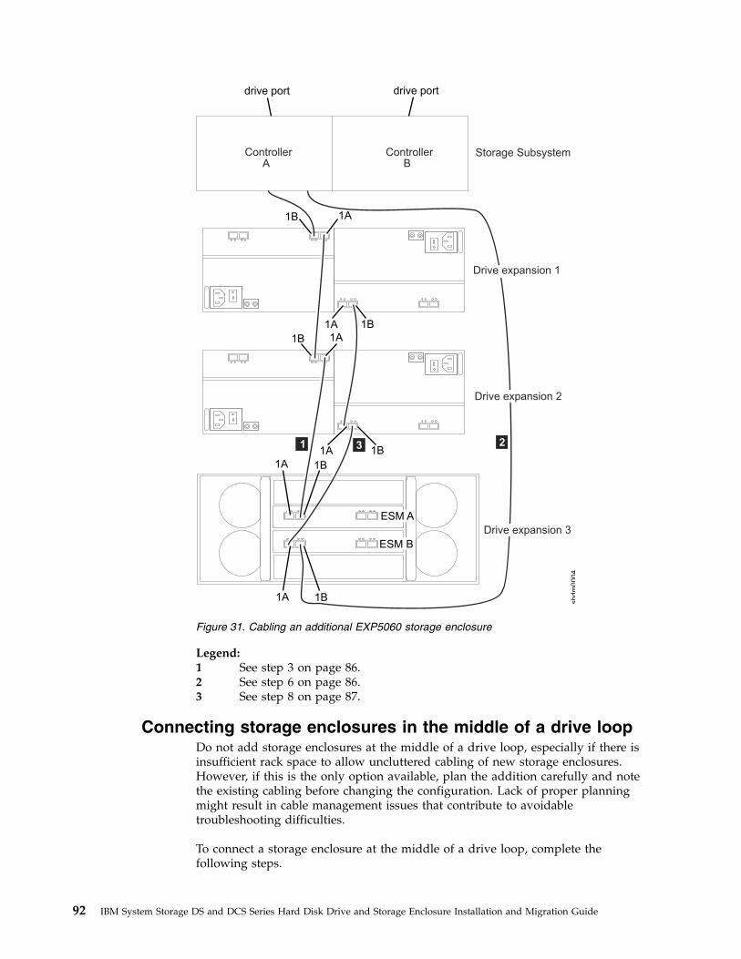
Legend:1 See step 3 on page 86.2 See step 6 on page 86.3 See step 8 on page 87.
Connecting storage enclosures in the middle of a drive loopDo not add storage enclosures at the middle of a drive loop, especially if there isinsufficient rack space to allow uncluttered cabling of new storage enclosures.However, if this is the only option available, plan the addition carefully and notethe existing cabling before changing the configuration. Lack of proper planningmight result in cable management issues that contribute to avoidabletroubleshooting difficulties.
To connect a storage enclosure at the middle of a drive loop, complete thefollowing steps.
ControllerA
ControllerB
1 23
drive port drive port
shdm
0004
1B 1A
1B1A
1B 1A
1B1A
1B1A
ESM B
ESM A
1B1A
Storage Subsystem
Drive expansion 1
Drive expansion 2
Drive expansion 3
Figure 31. Cabling an additional EXP5060 storage enclosure
92 IBM System Storage DS and DCS Series Hard Disk Drive and Storage Enclosure Installation and Migration Guide

Note: See “Examples of connecting storage enclosures at the middle of a driveloop” on page 95 for cabling illustrations and to identify the storage enclosuresthat are referred to in the steps.1. (For storage subsystem and storage enclosures with FC drive port connection
only) Insert the small form-factor pluggables (SFPs) or gigabit interfaceconverters (GBICs) into only those ports that you intend to use. Do not leaveGBICs or SFPs inserted into port connectors without connecting them to otherports by using cables. An unused SFP or GBIC, even pull slightly away fromthe socket might generate random errors in the drive loop/channel.
2. (For storage enclosures with mechanical enclosure ID switches) Change theenclosure ID to a unique number with a unique single (x1) digit. See “Settingenclosure IDs for enclosures in DS4000 and DS5000 storage subsystems” onpage 29.
3. Move the existing connection between the ESM port of the right ESM instorage enclosure 2 to the ESM port of the right ESM in storage enclosure 1 tothe ESM port of the new storage enclosure instead.
4. Ensure that there are not any drives fully inserted in the drive bays; then, turnon the power to the added storage enclosure.
5. Wait a few seconds. Check the drive port LEDs to ensure that the link to thenew storage enclosure is up and optimal and that there are no link problemsin the modified drive loop A. Ensure that the FC port bypass (FC ports) orSAS link service (SAS port) LEDs are not lit or intermittently lit. Using the DSStorage Manager Client Subsystem Management window, verify that thestorage enclosure is added and displayed in the Logical/Physical view of thewindow. To return the drive loop/channel to optimal state, see “Returning thedrive/loop channel to optimal state” on page 102.
6. Add a cabling connection between the ESM of the right ESM in storageenclosure 1 to the ESP port of the right ESM in the new storage enclosure.
7. Wait a few seconds. Check the drive port LEDs to ensure that the link to thenew storage enclosure is up and optimal and that there are no link problemsin the modified drive loop B. Ensure that the FC port bypass (FC ports) orSAS link service (SAS port) LEDs are not lit or intermittently lit. Using the DSStorage Manager Client Subsystem Management window, verify that thestorage enclosure is added and displayed in the Logical/Physical view of thewindow. To return the drive loop/channel to optimal state, see “Returning thedrive/loop channel to optimal state” on page 102.
Note: The existing storage enclosures are shown with Drive enclosure lostredundancy path errors until you establish the Fibre Channel cablingconnection described in step 8.
8. Move the existing connection between the ESM port of the left ESM in storageenclosure 1 to the ESM port of the left ESM in storage enclosure 2 to the ESMport of the new storage enclosure instead.
9. Wait a few seconds. Check the drive port LEDs to ensure that the link to thenew storage enclosure is up and optimal and that there are no link problemsin the modified drive loop B. Ensure that the FC port bypass (FC ports) orSAS link service (SAS port) LEDs are not lit or intermittently lit. Using the DSStorage Manager Client Subsystem Management window, verify that thestorage enclosure is added and displayed in the Logical/Physical view of thewindow. To return the drive loop/channel to optimal state, see “Returning thedrive/loop channel to optimal state” on page 102.
Chapter 3. Adding or migrating storage enclosures 93

Note: The existing storage enclosures are shown with Drive enclosure lostredundancy path errors until you establish the Fibre Channel cablingconnection described in step 8 on page 93.
10. Add a cabling connection between the ESM of the left ESM in storageenclosure 2 to the ESP port of the left ESM in the new storage enclosure.
11. Wait a few seconds. Check the drive port LEDs to ensure that the link to thenew storage enclosure is up and optimal and that there are no link problemsin the modified drive loop B. Ensure that the FC port bypass (FC ports) orSAS link service (SAS port) LEDs are not lit or intermittently lit. Using the DSStorage Manager Client Subsystem Management window, verify that thestorage enclosure is added and displayed in the Logical/Physical view of thewindow. To return the drive loop/channel to optimal state, see “Returning thedrive/loop channel to optimal state” on page 102.
Note: The existing storage enclosures are shown with Drive enclosure lostredundancy path errors until you establish the Fibre Channel cablingconnection described in step 8 on page 93.
12. The DS Storage Manager Client Subsystem Management window displays anew storage enclosure with no drives in the configuration.
Connecting storage enclosures at the middle of the best practicecable loop scheme in a DS4000 and DS5000 configurationFor storage subsystem configurations with an initial drive loop/channel cablingscheme similar to the scheme used in Figure 36 on page 103, Table 24 shows howyou cable the ports by adding a third expansion enclosure in the middle of the firstand second expansion enclosures. A port enclosed by () indicates that you removethe connection as part of the step.
Note: ESM ports for EXP700, EXP710, EXP100, EXP500, EXP3000, EXP3500, andDCS3700 storage expansion enclosure are referred to as IN and OUT. ESM portsfor EXP5060, EXP5000, EXP520, EXP395, EXP810, and EXP420 expansion enclosureare referred to as 1B and 1A. For more information, refer to the expansionenclosure Installation, User's, and Maintenance Guide.
Table 24. Connecting storage enclosures at the middle of the best practice cable loopscheme
Step Expansion enclosure 1 Expansion enclosure 2Expansion enclosure 3(new)
ControllerA
ControllerB
Left ESM Right ESM Left ESM Right ESM
3 on page93
(OUT/1B) IN/1A OUT/1B
6 on page93
OUT/1B IN/1A
8 on page93
OUT/1A (IN/1B) IN/1B
10 IN/1B OUT/1A
94 IBM System Storage DS and DCS Series Hard Disk Drive and Storage Enclosure Installation and Migration Guide

Connecting storage enclosures at the middle of a SAS drivecable loop scheme in a DS3000, DS3500, DCS3700, DCS3700with Performance Module Controllers, and DCS3860 storagesubsystem configurationFor DS3000, DS3500, DCS3700, DCS3700 with Performance Module Controllers,and DCS3860 storage subsystem configurations with an initial drive loop/channelcabling scheme that is similar to the scheme used in “Storage subsystem SAS drivechannel/loop schemes for enclosures in a DS3000 or DS3500 configuration” onpage 107, Table 25 shows how you cable the ports by adding a third expansionenclosure in the middle of the first and second expansion enclosures. A portenclosed by () indicates that you remove the connection as part of the step.
Table 25. Connecting storage enclosures at the middle of a SAS drive cable loop scheme ina DS3000, DS3500, DCS3700, DCS3700 with Performance Module Controllers, andDCS3860 configuration
Step Expansion enclosure 1 Expansion enclosure 2Expansion enclosure 3(new)
ControllerA
ControllerB
Left ESM Right ESM Left ESM Right ESM
3 on page93
(IN) OUT IN
6 on page93
IN IN OUT
8 on page93
(OUT) (IN) IN
10 on page94
OUT IN OUT
Examples of connecting storage enclosures at the middle of adrive loopThe following figures show examples of adding storage enclosures to the middle ofthe drive loop/channel configuration.
Chapter 3. Adding or migrating storage enclosures 95

Legend:1 See step 3 on page 93.2 See step 6 on page 93.3 See step 8 on page 93.4 See step 10 on page 94.
EXP810
EXP810
EXP810
EXP810
EXP810
EXP810
ControllerA
ControllerB
123 4
Driveenclosure1
Driveenclosure2
Driveenclosure3
drive port drive port
shdm
0005
1B 1A
1B1A
Figure 32. Cabling an additional storage enclosure to the middle of the drive loop in aDS5000 storage subsystem
96 IBM System Storage DS and DCS Series Hard Disk Drive and Storage Enclosure Installation and Migration Guide

Legend:1 See step 3 on page 93.2 See step 6 on page 93.3 See step 8 on page 93.4 See step 10 on page 94.
Connecting storage enclosures at the beginning (top) of adrive loop
Do not add storage enclosures at the top of a drive loop, especially if there isinsufficient rack space to allow uncluttered cabling. However, if this is the onlyoption available, plan the addition carefully and note the existing cabling beforechanging the configuration. Lack of proper planning might result in cablemanagement issues that contribute to avoidable troubleshooting difficulties.
Note: Do not add an EXP100 storage enclosure to the beginning of a drive loop ina DS4700 or DS4800 storage subsystem because of the drive cabling limitations andschemes shown in “Cabling EXP100, EXP710, and EXP810 storage enclosures inDS4700 and DS4800 configurations” on page 110. Instead, follow the instructions in“Connecting storage enclosures at the end (bottom) of a drive loop” on page 86. Ifthis is not possible, contact IBM support.
To connect a storage enclosure at the beginning of a drive loop, complete thefollowing steps.
shdm
0006
! !
! !
12
Driveenclosure2
Driveenclosure3
34
Driveenclosure1
drive port
IN OUT IN OUT
! !
drive port
Figure 33. Cabling an additional storage enclosure to the middle of the drive loop in aDS3000 storage subsystem configuration
Chapter 3. Adding or migrating storage enclosures 97

Note: See “Examples of connecting storage enclosures at the top of a drive loop”on page 100 for cabling illustrations and to identify the storage enclosures referredto in the steps.1. (For storage subsystem and storage enclosures with FC drive port connection
only) Insert the small form-factor pluggables (SFPs) or gigabit interfaceconverters (GBICs) into only those ports that you intend to use. Do not leaveGBICs or SFPs inserted into port connectors without connecting them to otherports by using cables. An unused SFP or GBIC, even pull slightly away fromthe socket might generate random errors in the drive loop/channel.
2. (For storage enclosures with mechanical enclosure ID switches) Change theenclosure ID to a unique number with a unique single (x1) digit. See “Settingenclosure IDs for enclosures in DS4000 and DS5000 storage subsystems” onpage 29.
3. Add a cabling connection between the ESM of the right ESM in storageenclosure 1 to the ESP port of the right ESM in the new storage enclosure.
4. Ensure that there are not any drives fully inserted in the drive bays; then, turnon the power to the added storage enclosure.
5. Wait a few seconds. Check the drive port LEDs to ensure that the link to thenew storage enclosure is up and optimal and that there are no link problemsin the modified drive loop A. Ensure that the FC port bypass (FC ports) orSAS link service (SAS port) LEDs are not lit or intermittently lit. Using the DSStorage Manager Client Subsystem Management window, verify that thestorage enclosure is added and displayed in the Logical/Physical view of thewindow. To return the drive loop/channel to optimal state, see “Returning thedrive/loop channel to optimal state” on page 102.
6. Move the existing connection between the controller A drive port to the ESMport of the left ESM in storage enclosure 1 to the ESM port of the left ESM inthe new storage enclosure instead.
7. Wait a few seconds. Check the drive port LEDs to ensure that the link to thenew storage enclosure is up and optimal and that there are no link problemsin the modified drive loop B. Ensure that the FC port bypass (FC ports) orSAS link service (SAS port) LEDs are not lit or intermittently lit. Using the DSStorage Manager Client Subsystem Management window, verify that thestorage enclosure is added and displayed in the Logical/Physical view of thewindow. To return the drive loop/channel to optimal state, see “Returning thedrive/loop channel to optimal state” on page 102.
Note: The existing storage enclosures are shown with Drive enclosure lostredundancy path errors until you establish the Fibre Channel cablingconnection described in step 8.
8. Add a cabling connection between the ESM of the left ESM in storageenclosure 1 to the ESP port of the left ESM in the new storage enclosure.
9. Wait a few seconds. Check the drive port LEDs to ensure that the link to thenew storage enclosure is up and optimal and that there are no link problemsin the modified drive loop B. Ensure that the FC port bypass (FC ports) orSAS link service (SAS port) LEDs are not lit or intermittently lit. Using the DSStorage Manager Client Subsystem Management window, verify that thestorage enclosure is added and displayed in the Logical/Physical view of thewindow. To return the drive loop/channel to optimal state, see “Returning thedrive/loop channel to optimal state” on page 102.
Note: The existing storage enclosures are shown with Drive enclosure lostredundancy path errors until you establish the Fibre Channel cablingconnection described in step 8.
98 IBM System Storage DS and DCS Series Hard Disk Drive and Storage Enclosure Installation and Migration Guide

10. Wait a few seconds. Check the drive port LEDs to ensure that the link to thenew storage enclosure is up and optimal and that there are no link problemsin the modified drive loop B. Ensure that the FC port bypass (FC ports) orSAS link service (SAS port) LEDs are not lit or intermittently lit. Using the DSStorage Manager Client Subsystem Management window, verify that thestorage enclosure is added and displayed in the Logical/Physical view of thewindow. To return the drive loop/channel to optimal state, see “Returning thedrive/loop channel to optimal state” on page 102.
Note: The existing storage enclosures are shown with Drive enclosure lostredundancy path errors until you establish the Fibre Channel cablingconnection described in step 8 on page 98.
11. The DS Storage Manager Client Subsystem Management window displays anew storage enclosure with no drives in the configuration.
Connecting storage enclosures at the top of the best practicecable loop scheme in a DS4000 or DS5000 configurationFor storage subsystem configurations with an initial drive loop/channel cablingscheme similar to the scheme used in Figure 36 on page 103, Table 26 shows howyou cable the ports by adding a third expansion enclosure at the top of the firstand second expansion enclosures. A port enclosed by () indicates that you removethe connection as part of the step.
Note: ESM ports for EXP700, EXP710, EXP100, EXP500, EXP3000, EXP3500, andDCS3700 storage expansion enclosure are referred to as IN and OUT. ESM portsfor EXP5060, EXP5000, EXP520, EXP395, EXP810, and EXP420 expansion enclosureare referred to as 1B and 1A. For more information, refer to the Installation, User's,and Maintenance Guide for the expansion enclosure.
Table 26. Connecting storage enclosures at the top of the best practice cable loop scheme
Step Storage subsystemStorage expansionenclosure 1
Storage expansionenclosure 3 (new)
ControllerA
ControllerB
Left ESM Right ESM Left ESM Right ESM
3 on page98
IN/1A OUT/1B
6 on page98
Drive portx
(IN/1B) IN/1B
8 on page98
IN/1B OUT/1A
Connecting storage enclosures at the top of a SAS drive cableloop scheme in a DS3000, DS3500, DCS3700, DCS3700 withPerformance Module Controllers, and DCS3860 storagesubsystem configurationFor DS3000, DS3500, DCS3700, DCS3700 with Performance Module Controllers, orDCS3860 storage subsystem configurations with an initial drive loop/channelcabling scheme that is similar to the scheme used in “Storage subsystem SAS drivechannel/loop schemes for enclosures in a DS3000 or DS3500 configuration” onpage 107, Table 27 on page 100 shows how you cable the ports by adding a thirdexpansion enclosure at the top of the first and second expansion enclosures. A portenclosed by () indicates that you remove the connection as part of the step.
Chapter 3. Adding or migrating storage enclosures 99

Note: ESM ports for EXP700, EXP710, EXP100, EXP500, EXP3000, EXP3500,DCS3700 storage expansion enclosure and DCS3860 are referred to as IN and OUT.ESM ports for EXP5060, EXP5000, EXP520, EXP395, EXP810, and EXP420 expansionenclosure are referred to as 1B and 1A. For more information, refer to theInstallation, User's, and Maintenance Guide for the expansion enclosure.
Table 27. Connecting storage enclosures at the top of a SAS drive cable loop scheme in aDS3000, DS3500, DCS3700, DCS3700 with Performance Module Controllers, or DCS3860configuration
Step Storage subsystemStorage expansionenclosure 1
Storage expansionenclosure 3 (new)
ControllerA
ControllerB
Left ESM Right ESM Left ESM Right ESM
3 on page98
OUT IN
6 on page98
Drive portx
(IN) IN
8 on page98
IN OUT
Examples of connecting storage enclosures at the top of a driveloopThe following figures show examples of adding storage enclosures to the top of thedrive loop/channel.
100 IBM System Storage DS and DCS Series Hard Disk Drive and Storage Enclosure Installation and Migration Guide
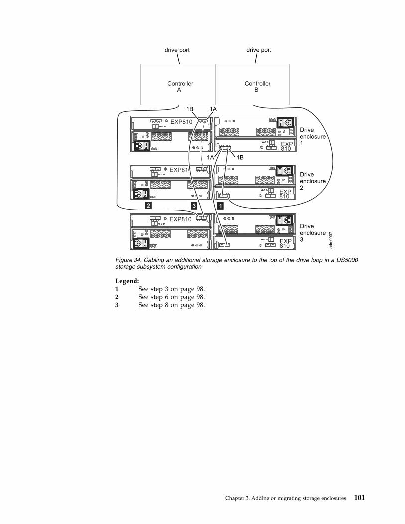
Legend:1 See step 3 on page 98.2 See step 6 on page 98.3 See step 8 on page 98.
EXP810
EXP810
EXP810
EXP810
EXP810
EXP810
ControllerA
ControllerB
drive port drive port
12 3
shdm
0007
Driveenclosure1
Driveenclosure2
Driveenclosure3
1B 1A
1A 1B
Figure 34. Cabling an additional storage enclosure to the top of the drive loop in a DS5000storage subsystem configuration
Chapter 3. Adding or migrating storage enclosures 101

Legend:1 See step 3 on page 98.2 See step 6 on page 98.3 See step 8 on page 98.
Returning the drive/loop channel to optimal stateTo return the drive loop/channel to optimal state, complete the following steps:1. Reseat the cable.2. Use a new cable.3. For a Fibre Channel port, use new SPFs or GBICs. Use the Fibre Channel
loopback to verify that the SFP and the Fibre Channel ports are in optimalstate.
4. Check the storage enclosure speed switch, if present.5. Check the new storage enclosure compatibility with the existing storage
enclosures.6. Check for any special cabling requirements.7. Perform any additional suggestions as indicated by the Recovery Guru function
in the Storage Subsystem Management window.8. If necessary, contact your IBM marketing representative or authorized reseller
for assistance.
ControllerA
ControllerB
drive port drive port
Driveenclosure1
Driveenclosure2
Driveenclosure3
shdm
0008
IN OUT IN OUT
12 3
Figure 35. Cabling an additional storage enclosure to the top of the drive loop in a DS3000storage subsystem configuration
102 IBM System Storage DS and DCS Series Hard Disk Drive and Storage Enclosure Installation and Migration Guide

9. If the problem remains, contact IBM support for assistance.
DS4000 and DS5000 storage subsystem Fibre Channel driveloop schemes
Although various Fibre Channel cable loop schemes are supported, to avoidproblems, consistently use one scheme when you connect DS4000 and DS5000storage subsystems and storage enclosures.
Note: In addition, there are specific restrictions that you must follow when youintermix EXP100 with EXP710 and EXP810 storage enclosures in a DS4700 orDS4800 storage subsystem configuration. See “Cabling EXP100, EXP710, andEXP810 storage enclosures in DS4700 and DS4800 configurations” on page 110 fordetails.
Figure 36 illustrates the best practice cable loop scheme for connecting DS4000storage subsystems and storage enclosures.
Legend:
1 Best practice cabling for EXP100, EXP500, EXP700, and EXP710 storageenclosures with DS4000 storage subsystems except when the EXP100storage enclosure is the first storage enclosure that is directly connected toa DS4700 or DS4800 storage subsystem controller A drive port. SeeFigure 38 on page 105 for cabling best practices that apply to this specificcase.
2 Best practice cabling for an EXP810 storage enclosure with a DS4000storage subsystem or a storage enclosure with a DS5000 storage subsystem.
To DS4000 storage subsystem drive ports
3 6
63
EXP
810
3 6
63
EXP
810
3 6
63
EXP
810
3 6
63
EXP
810
To DS4000 storage subsystem drive portsFor:EXP810
For:EXP100EXP700EXP710EXP500
1 2
Figure 36. Best practice cable loop scheme for connecting storage devices
Chapter 3. Adding or migrating storage enclosures 103
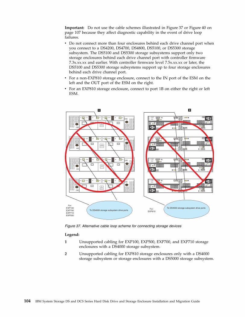
Important: Do not use the cable schemes illustrated in Figure 37 or Figure 40 onpage 107 because they affect diagnostic capability in the event of drive loopfailures.v Do not connect more than four enclosures behind each drive channel port when
you connect to a DS4200, DS4700, DS4800, DS5100, or DS5300 storagesubsystem. The DS5100 and DS5300 storage subsystems support only twostorage enclosures behind each drive channel port with controller firmware7.3x.xx.xx and earlier. With controller firmware level 7.5x.xx.xx or later, theDS5100 and DS5300 storage subsystems support up to four storage enclosuresbehind each drive channel port.
v For a non-EXP810 storage enclosure, connect to the IN port of the ESM on theleft and the OUT port of the ESM on the right.
v For an EXP810 storage enclosure, connect to port 1B on either the right or leftESM.
Legend:
1 Unsupported cabling for EXP100, EXP500, EXP700, and EXP710 storageenclosures with a DS4000 storage subsystem.
2 Unsupported cabling for EXP810 storage enclosures only with a DS4000storage subsystem or storage enclosures with a DS5000 storage subsystem.
To DS4000 storage subsystem drive ports
3 6
63
EXP
810
3 6
63
EXP
810
3 6
63
EXP
810
3 6
63
EXP
810
To DS4000 storage subsystem drive portsFor:
EXP100EXP700
EXP710
EXP500
For:EXP810
1 2
Figure 37. Alternative cable loop scheme for connecting storage devices
104 IBM System Storage DS and DCS Series Hard Disk Drive and Storage Enclosure Installation and Migration Guide

Legend:
1 Best practice cabling for the EXP100 storage enclosure with EXP710 orEXP810 storage enclosures in a DS4700 and DS4800 storage subsystemconfiguration only when the EXP100 storage enclosure is the first storageenclosure that is directly connected to controller A drive ports.(Unsupported for other DS4000 storage subsystems.) See “Cabling EXP100,EXP710, and EXP810 storage enclosures in DS4700 and DS4800configurations” on page 110 for more details.
2 Unsupported cabling for EXP810 storage enclosure only with a DS4000storage subsystem or storage enclosures with a DS5000 storage subsystem.
To DS4700/DS4800storage subsystem drive ports
3 6
63
EXP
810
3 6
63
EXP
810
3 6
63
EXP
810
3 6
63
EXP
810
To DS4000 storage subsystem drive ports
For:
EXP100EXP700
EXP710
EXP500
For:EXP810
12
Figure 38. Alternative cable loop scheme for connecting storage devices
Chapter 3. Adding or migrating storage enclosures 105

Legend:
1 Unsupported cabling for an EXP100, EXP500, EXP700, and EXP710 storageenclosure with a DS4000 storage subsystem.
2 Unsupported cabling for an EXP810 storage enclosure with a DS4000storage subsystem or a storage enclosure with a DS5000 storage subsystem.
Note: The cable loop scheme in Figure 39 is unsupported because both drive loopsare connected to the IN port of the EXP700 storage enclosure. Although thisrestriction does not specifically apply to other storage enclosures, you must avoidconnecting both drive loops in the IN port to prevent accidental unsupportedcabling in the EXP700 storage enclosure environment.
To DS4000 storage subsystem drive ports
For:
EXP100EXP700
EXP710
EXP500
3 6
63
EXP
810
3 6
63
EXP
810
3 6
63
EXP
810
3 6
63
EXP
810
To DS4000 storage subsystem drive portsFor:EXP810
1 2
Figure 39. Unsupported cable loop scheme for connecting storage devices (1 of 2)
106 IBM System Storage DS and DCS Series Hard Disk Drive and Storage Enclosure Installation and Migration Guide

Legend:
1 Unsupported cabling for an EXP100, EXP500, EXP700, and EXP710 storageenclosure with a DS4000 storage subsystem.
2 Unsupported cabling for an EXP810 storage enclosure with a DS4000storage subsystem or a storage enclosure with a DS5000 storage subsystem.
Note: The cable loop scheme in Figure 40 is unsupported because of the randompattern between the storage enclosures.
Storage subsystem SAS drive channel/loop schemes forenclosures in a DS3000 or DS3500 configuration
The following illustration shows the supported cabling configuration to connect aDS3000 or DS3500 storage subsystem to the storage enclosures and between thestorage enclosures with SAS drive channels.
To DS4000 storage subsystem drive ports
3 6
63
EXP
810
3 6
63
EXP
810
3 6
63
EXP
810
3 6
63
EXP
810
To DS4000 storage subsystem drive portsFor:
EXP810
1 2
For:EXP100EXP700EXP710EXP500
Figure 40. Unsupported cable loop scheme for connecting storage devices (2 of 2)
Chapter 3. Adding or migrating storage enclosures 107
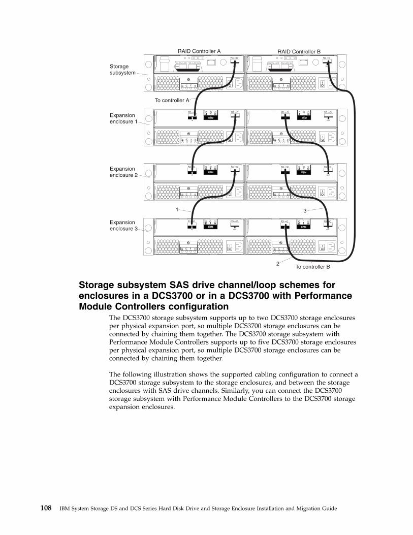
To controller B
RAID Controller A RAID Controller B
1
2
3
Storagesubsystem
Expansionenclosure 1
Expansionenclosure 2
Expansionenclosure 3
To controller A
Storage subsystem SAS drive channel/loop schemes forenclosures in a DCS3700 or in a DCS3700 with PerformanceModule Controllers configuration
The DCS3700 storage subsystem supports up to two DCS3700 storage enclosuresper physical expansion port, so multiple DCS3700 storage enclosures can beconnected by chaining them together. The DCS3700 storage subsystem withPerformance Module Controllers supports up to five DCS3700 storage enclosuresper physical expansion port, so multiple DCS3700 storage enclosures can beconnected by chaining them together.
The following illustration shows the supported cabling configuration to connect aDCS3700 storage subsystem to the storage enclosures, and between the storageenclosures with SAS drive channels. Similarly, you can connect the DCS3700storage subsystem with Performance Module Controllers to the DCS3700 storageexpansion enclosures.
108 IBM System Storage DS and DCS Series Hard Disk Drive and Storage Enclosure Installation and Migration Guide

To connect the DCS3700 storage system RAID controllers A and B to multipleDCS3700 expansion enclosures, complete the following steps:1. Connect the DCS3700 expansion enclosure to controller A:
a. Connect one end of a SAS cable to the drive expansion port on controller A.b. Connect the other end of the SAS cable to one of the In (↑) SAS connectors
on the ESM in SBB slot A in the DCS3700 expansion enclosure.2. Connect the SAS cable of the DCS3700 expansion enclosure to the next
DCS3700 expansion enclosure in the chain:a. Connect one end of a SAS cable to the Out (↓) SAS connector on the ESM in
SBB slot A of the DCS3700 expansion enclosure that you connected.b. Connect the other end of the SAS cable to one of the In (↑) SAS connectors
on the ESM in SBB slot A in the next DCS3700 expansion enclosure in thechain.
Chapter 3. Adding or migrating storage enclosures 109
3. Connect the last DCS3700 expansion enclosure in the chain to controller B:a. Connect one end of a SAS cable to the drive expansion port on controller B.b. Connect the other end of the SAS cable to one of the In (↑) SAS connectors
on the ESM in SBB slot B in the last DCS3700 expansion enclosures of thechain that you created.
4. In reverse order (last in chain to first in chain), connect the ESM in SBB slot Bto the DCS3700 first expansion enclosure in the chain:a. Connect one end of a SAS cable to the Out (↓) SAS connector on the right
ESM of the DCS3700 expansion enclosure that you just connected.
For detailed information about cabling the DCS3700 storage enclosures to theDCS3700 configuration, see the IBM System Storage DCS3700 Storage Subsystem andDCS3700 Storage Subsystem with Performance Module Controllers Installation, User's,and Maintenance Guide..
Cabling EXP100, EXP710, and EXP810 storage enclosures inDS4700 and DS4800 configurations
When you intermix EXP100, EXP710, and EXP810 storage enclosures, if it is notpossible to cable each group of enclosures by model type in a separate redundantdrive loop pair or behind each port of the dual-ported redundant drive channelpair, group them so that EXP810 storage enclosures are between EXP100 andEXP710 storage enclosures.
The following notes describe information that you must consider when an EXP100storage enclosure is the first storage enclosure that is cabled directly to thecontroller drive port in the storage subsystem:v Cable from the controller drive port to the OUT port on the left ESM (ESM A) of
the EXP100 storage enclosure.
Note: This is a change from previous cabling best practices in which you cabledfrom controller A drive port to the IN port on the left ESM (ESM A) of theEXP100 storage enclosure or any other storage enclosures as shown in theprevious section.
v If an EXP100 storage enclosure follows the initial EXP100 storage enclosure,cable from the IN port on the left ESM (ESM A) of the first EXP100 storageenclosure to the OUT port on the left ESM of the next EXP100 storage enclosure.Continue this cabling pattern until you encounter an EXP710 or EXP810 storageenclosure; then, cable from the IN port on the left ESM (ESM A) of the EXP100storage enclosure to the IN port of the EXP710 or EXP810 storage enclosure.
v If an EXP710 or EXP810 storage enclosure follows the initial EXP100 storageenclosure, cable from the IN port on the left ESM (ESM A) of the EXP100 storageenclosure to the IN port of the EXP710 or EXP810 storage enclosure. To cable tothe next storage enclosure in the chain, cable from the OUT port of the left ESMof the EXP710 or EXP810 storage enclosure to the IN port of the next storageenclosure.
v Continue the left ESM (ESM A) cabling pattern by cabling from the OUT port tothe IN port on subsequent storage enclosures until you complete the chain.
Figure 41 on page 111 shows a supported EXP710, EXP810, and EXP100 storageenclosure intermix configuration in a DS4700 or DS4800 storage subsystem. Thecabling is supported because it follows the cabling best practices. The cablingscheme of the DS4000 storage subsystem on the right of the figure shows nochange because the EXP100 storage enclosure is not directly connected as the first
110 IBM System Storage DS and DCS Series Hard Disk Drive and Storage Enclosure Installation and Migration Guide

storage enclosure to controller drive port A of the DS4000 storage subsystem.
Table 28. Description of the figure that shows supported EXP710, EXP810, and EXP100storage enclosure intermix configuration in a DS4700 or DS4800 storage subsystem
Number Description
1 DS4700 or DS4800 storage subsystem
2 EXP100 storage enclosure
3 EXP810 storage enclosure
4 IN port
5 OUT port
6 Port 1B
7 Port 1A
Figure 42 on page 112 shows an unsupported EXP710, EXP810, and EXP100 storageenclosure intermix configuration in a DS4700 or DS4800 storage subsystem. Thecabling is unsupported because controller A is cabled to the IN port on the leftESM of the first EXP100.
Out
OutOut
Out
In In
In InEXP100
ESM A
ESM A ESM B
ESM B
EXP810
ESM A
ESM B
ESM A
ESM B
DS4700/DS4800 storage subsystem
EXP810
EXP100
ESM A
ESM B
ESM A
ESM B
ESM A
ESM A
ESM B
ESM B
In Out In Out
In Out In Out
Port 1B Port 1A
Port 1A Port 1B
Port 1B Port 1A
Port 1A Port 1B
Port 1B
Port 1B
Port 1A
Port 1A
Port 1A
Port 1A Port 1B
Port 1B
DS4700/DS4800 storage subsystem
Figure 41. Supported EXP710, EXP810, and EXP100 storage enclosure intermixconfiguration in a DS4700 or DS4800 storage subsystem
Chapter 3. Adding or migrating storage enclosures 111

Table 29. Description of the figure that shows an unsupported EXP710, EXP810, andEXP100 storage enclosure intermix configuration in a DS4700 or DS4800 storage subsystem
Number Description
1 DS4700 or DS4800 storage subsystem
2 EXP100 storage enclosure
3 EXP810 storage enclosure
4 IN port
5 OUT port
6 Port 1B
7 Port 1A
DS4700/DS4800 storage subsystem
EXP100
ESM A ESM B
ESM A ESM B
EXP810
ESM A
ESM A
ESM B
ESM B
In InOut Out
In Out In Out
Port 1B
Port 1B
Port 1B
Port 1B
Port 1A
Port 1A
Port 1A
Port 1A
Figure 42. Unsupported EXP710, EXP810, and EXP100 storage enclosure intermixconfiguration in a DS4700 or DS4800 storage subsystem
112 IBM System Storage DS and DCS Series Hard Disk Drive and Storage Enclosure Installation and Migration Guide
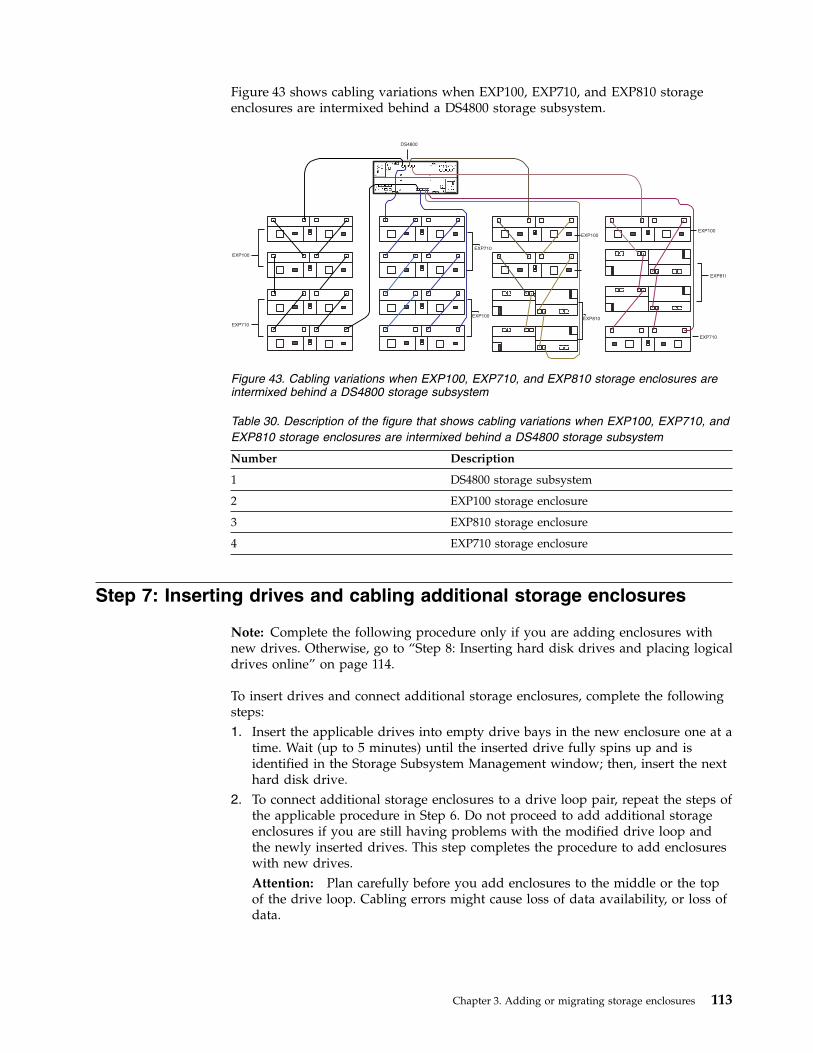
Figure 43 shows cabling variations when EXP100, EXP710, and EXP810 storageenclosures are intermixed behind a DS4800 storage subsystem.
Table 30. Description of the figure that shows cabling variations when EXP100, EXP710, andEXP810 storage enclosures are intermixed behind a DS4800 storage subsystem
Number Description
1 DS4800 storage subsystem
2 EXP100 storage enclosure
3 EXP810 storage enclosure
4 EXP710 storage enclosure
Step 7: Inserting drives and cabling additional storage enclosures
Note: Complete the following procedure only if you are adding enclosures withnew drives. Otherwise, go to “Step 8: Inserting hard disk drives and placing logicaldrives online” on page 114.
To insert drives and connect additional storage enclosures, complete the followingsteps:1. Insert the applicable drives into empty drive bays in the new enclosure one at a
time. Wait (up to 5 minutes) until the inserted drive fully spins up and isidentified in the Storage Subsystem Management window; then, insert the nexthard disk drive.
2. To connect additional storage enclosures to a drive loop pair, repeat the steps ofthe applicable procedure in Step 6. Do not proceed to add additional storageenclosures if you are still having problems with the modified drive loop andthe newly inserted drives. This step completes the procedure to add enclosureswith new drives.Attention: Plan carefully before you add enclosures to the middle or the topof the drive loop. Cabling errors might cause loss of data availability, or loss ofdata.
DS4800
EXP100
EXP710
EXP710
EXP100EXP810
EXP100
EXP100
EXP810
EXP710
Figure 43. Cabling variations when EXP100, EXP710, and EXP810 storage enclosures areintermixed behind a DS4800 storage subsystem
Chapter 3. Adding or migrating storage enclosures 113

Step 8: Inserting hard disk drives and placing logical drives online
Note: To ensure that the arrays are on the Storage Subsystem Managementwindow, move all of the hard disk drives as independent sets when you migratehard disk drives from multiple storage subsystems to a single storage subsystem.Ensure that each set successfully transfers before you move another set of drives.
To migrate enclosures with drives that contain logical drive configuration data,complete the following steps:1. For each additional enclosure that you intend to migrate to the drive loop pair,
perform the procedure in “Step 5: Installing and setting storage enclosure IDsand speeds” on page 83 and “Step 6: Cabling, turning on, and verifying storageenclosure operation” on page 84.Attention: Plan carefully before you add enclosures to the middle or the topof the drive loop. Cabling errors might cause loss of data availability, or loss ofdata.
2. Insert the drives into the empty drive bays in the new enclosure, one at a time.Wait (up to 5 minutes) until each drive pair fully spins up and is identified inthe Storage Subsystem Management window; then, insert the next hard diskdrive pair.
3. The array and logical drive information is shown on the Logical/Physical viewof the Storage Subsystem Management window. The storage subsystem placesthe array in Offline state until you insert all the drives in the array.
Note: On storage subsystems with controller firmware level 7.xx or later orStorage Manager software version 10.xx or later, arrays appear in Contingentstate (with an arrow icon) until all of the drives in the array are inserted. Thearray appears in Exported - ready to import state.
4. If the migrated drives are FDE drives and were configured as part of a securedarray, use the saved security key from the storage subsystems that these drivesare migrated from to unlock the drives. Without this security key, thecontrollers cannot unlock the drives to retrieve the array configuration data anddata on the drives.
5. Depending on the controller firmware and Storage Manager software versionsof your system, complete one of the following steps:v With controller firmware earlier than level 7.xx and Storage Manager
software earlier than version 10.xx, after you insert all of the drives,manually change the state of the arrays and logical drives that are involvedfrom Optimal state to Online state if it is not changed automatically. To doso, right-click the array name in the Storage Subsystem Management windowand click Place -> Online.
v With controller firmware level 7.xx or later and Storage Manager softwareversion 10.xx or later, after you insert all of the drives, import the array,using the Import Array function, and complete the following steps:a. Click the name of the array that you want to import in the Storage
Subsystem Management window.b. Click Advanced -> Maintenance -> Import Array.c. In the confirmation window, click OK.d. Click Import.e. In the Import Array window, type yes and click OK.f. Click Close.
6. If any of the following conditions remain, contact IBM support for assistance.
114 IBM System Storage DS and DCS Series Hard Disk Drive and Storage Enclosure Installation and Migration Guide

v The Empty Drive Bay icon ( ) is displayed for the drive bay into whichyou inserted the migrating drive.
v The Failed Unconfigured Drive icon ( ) or the Failed Configured Drive
icon ( ) is displayed for the drive bay into which you inserted themigrating drive.
v Array configuration data on the drives that you added is incomplete.v You cannot bring the array online (controller firmware level 6.xx.xx.xx and
earlier) or import the array (controller firmware level 7.xx.xx.xx or later).
Attention: Do not initialize a hard disk drive that you want to keep (byright-clicking its icon and selecting Initialize from the pull-down menu) if itcontains configuration or user data. Initializing any of the drives in a definedarray causes all hard disk drives in an array to return to the UnconfiguredCapacity storage pool, deleting their array definitions from the configuration.The user data on such drives is lost.
Result: When the arrays are online, they are ready for you to configure andmap to host servers. You might also then re-create FlashCopy images andremote mirror relationships.
7. Use the DS Storage Manager program to view the storage partitioningdefinitions and make any necessary corrections.
8. The storage subsystem that the drives are migrated from displays the logicaldrives that are defined in these drives as missing LUNs. To remove thesemissing LUN entries, right-click each entry and select Delete from the menu.
You completed the procedure for migrating enclosures.
Chapter 3. Adding or migrating storage enclosures 115

116 IBM System Storage DS and DCS Series Hard Disk Drive and Storage Enclosure Installation and Migration Guide

Chapter 4. Upgrading a storage subsystem controller
This chapter describes the procedure to replace the storage subsystem controller ina working configuration with a new storage subsystem controller of the same ordifferent model. All the hard disk drives and storage enclosures in the originalconfiguration are part of the new configuration. Use the procedures in this chapteronly if no drives are attached to the new storage subsystem. This procedure is alsoreferred to as controller head-swapping. If the new storage subsystem is part of aworking configuration where the storage subsystem controllers are booted with atleast two drives, see Chapter 3, “Adding or migrating storage enclosures,” on page75 to migrate the drives and storage enclosures instead.
IBM support is available for controller upgrade assistance, but you must contactyour IBM marketing representative or authorized reseller as first-line support. Formore information, see “Getting information, help, and service,” on page 147.
Only the replacement of the controller in a single working storage subsystemconfiguration with another controller is supported. To consolidate the storageenclosures behind multiple controllers in multiple working storage subsystemconfigurations, perform the applicable controller swap procedure that is describedin this chapter to upgrade one working storage subsystem configuration. Then, seeChapter 3, “Adding or migrating storage enclosures,” on page 75 for instructionsfor migrating the storage enclosures in the other storage subsystems into the newcontroller storage subsystem configuration.
A readme file is available with the latest information and instructions for eachstorage subsystem. To access the most recent readme file, see “Finding StorageManager software, controller firmware, and readme files” on page 147.
Upgrade considerationsConsider the following information before you upgrade a storage subsystem.
Host attachment and premium feature entitlementsThe following notes describe information about host attachment and premiumfeature entitlements that you must consider before you upgrade a storagesubsystem.v To enable premium features in a new or replacement configuration that were
enabled in an original configuration, you must purchase the applicableentitlements for the new or replacement storage subsystem, if that premiumfeature is not standard in the new or replacement storage subsystem. Inaddition, IBM assigns host attachment kits only to specific storage subsystems.You must also purchase the applicable host attachment kits for new orreplacement storage subsystems.
v After the upgrade, premium features that were previously enabled in theoriginal storage subsystem along with the enable-by-default premium features inthe new storage subsystem are automatically placed in Out of Compliance state.You must generate new premium feature SAFE keys to re-enable premiumfeatures.
© Copyright IBM Corp. 2008, 2013 117

Follow the instructions in the Premium Features Activation instructions thatcome with the Premium Feature kits to generate the premium feature keys. Also,to generate new premium feature keys, go to http://www-912.ibm.com/PremiumFeatures/.
Storage firmware migrationThe following notes describe information about controller firmware migration thatyou must consider before you upgrade a storage subsystem:v You can migrate the drives and storage enclosures in a storage subsystem to a
new controller only if the firmware in the controllers of the storage subsystemand the new controller have the same major release version. Only major releaseversions 6.xx and 7.xx are supported.
v Before you perform a migration from an original storage subsystem controllerwith firmware version 6.xx to a new storage subsystem controller with firmwareversion 6.xx, you must upgrade the original and the new storage subsystemcontroller firmware to the latest version 6.xx.
v To perform a migration from an original storage subsystem controller withfirmware version 7.xx to a new storage subsystem controller with firmwareversion 7.xx, the controller firmware version in the original controller must bethe same as or earlier than the controller firmware version in the new controller.As an exception, if either the original or the new DS3500, DCS3700, or DCS3700subsystem with Performance Module Controllers has controller firmware version7.8x.xx.xx installed, the original and the new DS3500, DCS3700, or DCS3700 withPerformance Module Controllers must be upgraded to the same version as thatof the 7.8x.xx.xx controller firmware, before the head-swap. Two extra newdrives might need to be purchased to bring up the new storage subsystem forcontroller firmware upgrading. Otherwise, the controller firmware in the newcontroller is placed in the Controller Lock Down state.Complete the following steps, if the 7.xx firmware version in the new storagesubsystem is earlier than the 7.xx firmware version in the original controller:1. Purchase two additional hard disk drives.2. Build a configuration with the new hard disk drives and the new subsystem
enclosure. You might also need to add a drive expansion enclosure if thereare not any available drive slots in the new storage subsystem enclosure.
3. Use the storage enclosure or drive migration procedures that are listed in thisdocument to add existing enclosures or hard disk drives to the new storagesubsystem configuration.
4. After successful migration, remove the storage enclosure with which youstarted the new storage subsystem, if necessary.
v Before you perform a migration from an original storage subsystem controllerwith firmware version 6.xx or earlier to a new storage subsystem controller withfirmware version 7.xx or later, you must upgrade the original storage subsystemcontroller firmware to version 7.xx or later. Otherwise, the controller firmware inthe new controller is placed in the Controller Lock Down state.
v Before you perform a migration from an original storage subsystem controllerwith firmware version 7.xx or later to a new storage subsystem controller withfirmware version 6.xx or earlier, you must upgrade the new storage subsystemcontroller firmware to version 7.xx or later. You must purchase two additionaldrives and a storage enclosure to bring the new storage subsystem controllerinto Optimal state with drives attached before you can update the controllerfirmware. If the upgrade of the new storage subsystem controller firmware toversion 7.xx or later is not possible, the drives that are configured in the storage
118 IBM System Storage DS and DCS Series Hard Disk Drive and Storage Enclosure Installation and Migration Guide

subsystem with firmware version 7.xx or later cannot be migrated into a storagesubsystem with controller firmware 6.xx or earlier.Complete the following steps, if the upgrade of the new storage subsystemcontroller firmware to version 7.xx or later is possible:1. Purchase two additional hard disk drives and build a configuration with the
new hard disk drives and the new subsystem enclosure. You might also needto add a drive expansion enclosure if there are not any available drive slotsin the new storage subsystem enclosure.
2. Use the storage enclosure or drive migration procedures that are listed in thisdocument to add existing enclosures or drives to the new storage subsystemconfiguration.
3. After successful migration, remove the storage subsystem configuration thatyou built in step 1, if necessary.
Note: For more information, see the “Drive migration limitations” on page 15section.
Alternative procedure to upgrade a storage subsystemcontroller enclosure
There is an alternative method to upgrade a storage subsystem controllerenclosure. To bring the new storage subsystem controller into an optimal state, youmust obtain a minimum of two new drives and a storage expansion enclosure (ifthe storage subsystem controller did not have any available drive slots). Then youmust migrate the drives and drive expansion enclosure from the original storagesubsystem to the new storage subsystem.
To upgrade the storage subsystem controller by using this alternative method,complete the following steps:1. Plan the upgrade. For more information, refer to step 1 on page 128.2. Purchase two new drives and a drive expansion enclosure (if there are not any
available drive slots in the new storage subsystem).3. Prepare the new storage subsystem for the upgrade:
a. Unpack the new storage subsystem, and install it in a rack.b. If required, unpack and connect the storage enclosure to the new storage
subsystem. Install the two new drives in the drive slots.c. Power on the drive expansion enclosure (if installed) and the storage
subsystem.d. Connect the new storage subsystem to the systems management network.
Use the default IP addresses of the controllers, and record the version of thecontroller firmware on the new storage subsystem.The default TCP/IP address of controller A Ethernet port 1 is192.168.128.101. The default TCP/IP address of controller A Ethernet port2 is 192.168.129.101. The default TCP/IP address of controller B Ethernetport 1 is 192.168.128.102. The default TCP/IP address of controller BEthernet port 2 is 192.168.129.102.
4. Prepare the original storage subsystem for the upgrade. For more information,refer to step 3 on page 129.
5. Update the controller firmware in the new storage subsystem with the latestonline version. To determine the appropriate version of firmware to be installedin the new storage subsystem, refer to Figure 44 on page 131.
Chapter 4. Upgrading a storage subsystem controller 119

a. Perform steps 4c-4g (see 4 on page 130) and 5a or 5b and 5c (see 5 on page133) to upgrade the controller firmware and to switch from the original tothe new storage subsystem.
6. Migrate the drive and drive expansion enclosures to the new storage subsystemconfiguration. For more information, refer to “Migrating storage enclosureswith hard disk drives that have defined logical drive configurations” on page79.
7. Prepare the new storage subsystem for use. For more information, refer to step6 on page 134.
Supported upgradesThe following notes describe information about the supported upgrades that youmust consider before you upgrade a storage subsystem:v Migrating from a configuration with an integrated drive/RAID controller
DS4000 storage subsystem to one with the RAID controller requires only anadditional storage enclosure for the drives that are installed in the integrateddrive/RAID controller.
v Some storage subsystem models require that hard disk drives and storageenclosures operate at a specified Fibre Channel speed. Ensure that the hard diskdrive and storage enclosures can operate at that speed before you begin theupgrade.
v As of the date of this document, IBM does not support replacement of SATA orFibre Channel controllers with one another. Contact your IBM marketingrepresentative or authorized reseller for information.
The following table describes the supported storage subsystem upgrades. You cansubmit a request for price quote (RPQ) to your IBM marketing representative orauthorized reseller for upgrading scenarios of the storage subsystem that are notdescribed in this table.
Table 31. Supported replacement storage subsystems
Storage subsystem model Supported replacement storage subsystem models
DS3200, DS3300, DS3400 DS3200, DS3300, DS3400
DS3512 DS3512 (DS3524)
The DS3512 storage subsystem can be replaced with a DS3524 storage subsystem onlyif an EXP3512 storage enclosure is available to house the drives in the DS3512 storagesubsystem. The DS3512 storage subsystem supports 3.5-inch drives and the DS3524storage subsystem supports 2.5-inch drives. Also, the DS3524 storage subsystem mustbe purchased with the minimum number of drives for optimal operation.
The existing storage subsystem must be upgraded to controller firmware version7.8x.xx.xx before the drives in that storage subsystem are head-swapped to a storagesubsystem with controller firmware version 7.8x.xx.xx.
120 IBM System Storage DS and DCS Series Hard Disk Drive and Storage Enclosure Installation and Migration Guide
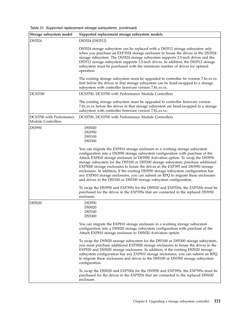
Table 31. Supported replacement storage subsystems (continued)
Storage subsystem model Supported replacement storage subsystem models
DS3524 DS3524 (DS3512)
DS3524 storage subsystem can be replaced with a DS3512 storage subsystem onlywhen you purchase an EXP3524 storage enclosure to house the drives in the DS3524storage subsystem. The DS3524 storage subsystem supports 2.5-inch drives and theDS3512 storage subsystem supports 3.5-inch drives. In addition, the DS3512 storagesubsystem must be purchased with the minimum number of drives for optimaloperation.
The existing storage subsystem must be upgraded to controller fw version 7.8x.xx.xxfirst before the drives in that storage subsystem can be head-swapped to a storagesubsystem with controller firmware version 7.8x.xx.xx.
DCS3700 DCS3700, DCS3700 with Performance Module Controllers
The existing storage subsystem must be upgraded to controller firmware version7.8x.xx.xx before the drives in that storage subsystem are head-swapped to a storagesubsystem with controller firmware version 7.8x.xx.xx.
DCS3700 with PerformanceModule Controllers
DCS3700, DCS3700 with Performance Module Controllers
DS3950 DS5020DS3950DS5100DS5300
You can migrate the EXP810 storage enclosure in a working storage subsystemconfiguration into a DS3950 storage subsystem configuration with purchase of theAttach EXP810 storage enclosure to DS3950 Activation option. To swap the DS3950storage subsystem for the DS5100 or DS5300 storage subsystem, purchase additionalEXP5000 storage enclosures to house the drives in the EXP395 and DS3950 storageenclosures. In addition, if the existing DS3950 storage subsystem configuration hasany EXP810 storage enclosures, you can submit an RPQ to migrate these enclosuresand drives to the DS5100 or DS5300 storage subsystem configuration.
To swap the DS3950 and EXP395s for the DS5020 and EXP520s, the EXP520s must bepurchased for the drives in the EXP395s that are connected to the replaced DS3950enclosure.
DS5020 DS3950DS5020DS5100DS5300
You can migrate the EXP810 storage enclosure in a working storage subsystemconfiguration into a DS5020 storage subsystem configuration with purchase of theAttach EXP810 storage enclosure to DS5020 Activation option.
To swap the DS5020 storage subsystem for the DS5100 or DS5300 storage subsystem,you must purchase additional EXP5000 storage enclosures to house the drives in theEXP520 and DS5020 storage enclosures. In addition, if the existing DS5020 storagesubsystem configuration has any EXP810 storage enclosures, you can submit an RPQto migrate these enclosures and drives to the DS5100 or DS5300 storage subsystemconfiguration.
To swap the DS5020 and EXP520s for the DS3950 and EXP395s, the EXP395s must bepurchased for the drives in the EXP520s that are connected to the replaced DS5020enclosure.
Chapter 4. Upgrading a storage subsystem controller 121

Table 31. Supported replacement storage subsystems (continued)
Storage subsystem model Supported replacement storage subsystem models
DS5100DS5300 DS3950DS5020DS5100DS5300
The EXP5000 (1818-D1A) and EXP5060 storage enclosures are designed for the DS5100and DS5300 (1818-51A and 1818-53A) storage subsystem and are the only storageenclosures that are supported behind the DS5100 and DS5300 storage subsystems.
You can submit an RPQ to migrate the EXP810 storage enclosures in a workingstorage subsystem configuration into a DS5100 or DS5300 storage subsystemconfiguration.
To swap the DS5100 or DS5300 storage subsystem enclosure for the DS5020 storagesubsystem or the DS3950 storage subsystem, you must purchase additional EXP520storage enclosures or EXP395 storage enclosures to house the drives in the EXP5000storage enclosures. In addition, if the existing DS5100 or DS5300 storage subsystemconfiguration has any EXP810 storage enclosures, these enclosures and drives can alsobe migrated to the DS5020 storage subsystem or DS3950 storage subsystemconfiguration with the purchase of the Attach EXP810 storage enclosure to DS5020 orDS3950 Activation option.
If the existing DS5100 or DS5300 storage subsystem configuration has any EXP5060storage enclosures, these enclosures and drives cannot be migrated to the new DS5020storage subsystem configuration. No storage enclosures are compatible with theDS5020 storage subsystems that can be used to house the drives from the EXP5060storage enclosures. Similarly, you cannot migrate SDD or FDE drives from a DS5100or DS5300 storage subsystem configuration to a DS3950 storage subsystemconfiguration. Additionally, you can only migrate SSD or FDE drives from a DS5100or DS53000 storage subsystem configuration to a DS5020 storage subsystemconfiguration. You also need to purchase additional premium feature keys (such asthe FDE premium feature key) to support the migration of FDE drives from a DS5100or DS5300 storage subsystem. A fully configured DS5100 or DS5300 storage subsystemrequires multiple DS5020 or DS3950 subsystems in order to migrate all of the drivesin the configuration.
The DS5020 and DS3950 storage subsystem requires firmware level 7.60.xx.xx or later.
122 IBM System Storage DS and DCS Series Hard Disk Drive and Storage Enclosure Installation and Migration Guide

Table 31. Supported replacement storage subsystems (continued)
Storage subsystem model Supported replacement storage subsystem models
DS4700 ExpressDS4800 DS4300 base modelDS4300 with turbo optionDS4400DS4500DS4700 ExpressDS4800DS5020DS5100DS5300
Migration to a DS4300, DS4400, and DS4500 storage subsystems requires that thedrive enclosures be operating at 2-Gbps Fibre Channel speed.
The DS4800 and DS4700 Express storage subsystems do not support EXP700 (orEXP500) storage enclosures. The EXP700 storage enclosures must be upgraded toEXP710 storage enclosures in the existing DS4000 storage subsystem configurationbefore you migrate it to the DS4700 Express or DS4800 storage subsystem. (Because oflimited parts inventory as of the date of this document, no upgrade is available for anEXP700 to EXP710 storage enclosure upgrade. An RPQ approval is required for theEXP700 storage enclosure to be supported at the 06.60.xx.xx code level.)
You cannot replace a DS4800 or a DS4700 Express storage subsystem with a DS4400storage subsystem, if the existing DS4800 storage subsystem configuration has EXP810storage enclosures in the drive channels.
Migrating more than six EXP710 storage enclosures to a DS4700 Express subsystemrequires two DS4700 Express storage subsystems; a maximum of six EXP710 storageenclosures can be attached to a DS4700 Express storage subsystem.
If a DS5000 (DS5020/DS5100/DS5300) storage subsystem is used to replace a DS4000storage subsystem with controller firmware level 6.xx, you must upgrade the DS4000storage subsystem controller firmware to version 7.xx.xx.xx first. For moreinformation about storage subsystem and storage enclosure compatibility, see Table 9on page 24. For information about controller firmware compatibility, see Table 2 onpage 9.
The DS5020 storage subsystem requires controller firmware level 7.60.xx.xx or later.The DS5100 or DS5300 storage subsystem requires controller firmware level 7.30.xx orlater.
Migration to a DS4300 storage subsystem configuration from a DS4400, DS4500, orDS4800 storage subsystem configuration with more than eight storage enclosuresrequires more than one DS4300 storage subsystem. See Table 1 on page 4.
The DS4300 turbo and DS4500 storage subsystem requires controller firmware level6.19.xx.xx or later to support the EXP810 storage enclosure attachment.
The DS4400 storage subsystem does not support the EXP810 storage enclosures.Migration to the DS4300, DS4400, and DS4500 storage subsystems require the DS4700and DS4800 controller firmware version 6.xx.
Existing EXP810 storage enclosures can be migrated from currently installed DS4700or DS4800 storage subsystems to attach to a DS5000 storage subsystem through theRPQ process.
DS4200 Express DS4200 Express
Chapter 4. Upgrading a storage subsystem controller 123

Table 31. Supported replacement storage subsystems (continued)
Storage subsystem model Supported replacement storage subsystem models
DS4400DS4500 DS4300 base modelDS4300 with turbo optionDS4400DS4500DS4700 ExpressDS4800
Migration to a DS4300 storage subsystem configuration from a DS4400, DS4500, orDS4800 storage subsystem configuration with more than eight storage enclosuresrequires more than one DS4300 storage subsystem. See Table 1 on page 4.
The DS4800 and DS4700 Express storage subsystems do not support EXP700 orEXP500 storage enclosures. The EXP700 storage enclosures must be upgraded toEXP710 storage enclosures in the existing DS4000 storage subsystem configurationbefore you migrate it to the DS4700 Express or DS4800 storage subsystem. Because oflimited parts inventory as of the date of this document, no upgrade is available for anEXP700 to EXP710 storage enclosure upgrade. An RPQ approval is required for theEXP700 storage enclosure to be supported with firmware version 6.60.
Migration to a DS4700 Express or DS4800 storage subsystems require that the DS4700or DS4800 storage subsystem contain firmware version 6.xx.
The DS4300 and DS4500 storage subsystem requires controller firmware level6.19.xx.xx or later to support the EXP810 storage enclosure.
DS4300 base model (dualcontroller basemodel)DS4300 turbo (dualcontroller model with turbooption)
DS4300 base modelDS4300 with turbo optionDS4400DS4500DS4700 ExpressDS4800
DS4300 base model and DS4300 with turbo option storage subsystem configurationsdo not accommodate EXP500 storage enclosures. Do not migrate the EXP500 storageenclosures in DS4400 or DS4500 storage subsystem configurations to DS4300 basemodel and DS4300 with turbo option storage subsystem configurations.
Migration to the DS4700 Express and DS4800 storage subsystems requires that theDS4700 and DS4800 contain firmware version 6.xx.xx.xx.
The DS4300 and DS4500 storage subsystem requires controller firmware level6.19.xx.xx or later to support the EXP810 storage enclosure.
DS4300 single controller DS4300 single controllerDS4300 baseDS4300 with turbo option
124 IBM System Storage DS and DCS Series Hard Disk Drive and Storage Enclosure Installation and Migration Guide

Table 31. Supported replacement storage subsystems (continued)
Storage subsystem model Supported replacement storage subsystem models
DS4100 base DS4100 baseDS4500DS4700 ExpressDS4800
For the DS4100 base storage subsystem, you must run the following SMclientcommand to enable dual controller (duplex) operation:
set storageSubsystem redundancyMode=duplex;
See the online help for information about how to run SMclient commands.
For the DS4800 base storage subsystem, the required firmware is version 06.15.2x.xx,and there must not be an attached EXP810 storage enclosure.
For the DS4500, DS4700 Express, and DS4800 storage subsystems, the FibreChannel/SATA intermix premium feature might be required. Additionally, EXP100storage enclosures must be used to migrate the drives in the DS4100 bays.
Migration to the DS4700 Express and DS4800 storage subsystems requires that theDS4700 and DS4800 contain firmware version 6.xx.xx.xx.
The DS4500 storage subsystem requires controller firmware level 6.19.xx.xx or later tosupport the EXP810 storage enclosure.
DS4100 single controller DS4100 single controllerDS4100 base
For the DS4100 base storage subsystem, you must run the following SMclientcommand to enable dual controller (duplex) operation:
set storageSubsystem redundancyMode=duplex;
See the online help for information about how to run SMclient commands.
Configuration behavior after an upgrade and storagesubsystem replacement
The following notes describe the identifier and premium feature behavior after anupgrade and storage subsystem replacement:v Worldwide name (WWN):
The worldwide names that the original storage subsystem uses before theupgrade are not returned when the upgrade is complete. Instead, the newstorage subsystem is identified by WWNs that are based on a new embeddedunique identifier.See your application documentation, device-driver user guide, or relateddocumentation for detailed instructions for updating the WWN of the storagesubsystem in the application or device driver. Additionally, to review the readmefile and the related IBM System Storage DS Storage Manager Installation andSupport Guide for information about any preparation tasks oroperating-system-specific restrictions, go to http://www.ibm.com/systems/support/storage/disk/.
v Controller IP addresses:When the storage subsystem controllers are assigned static IP addresses, the IPaddresses are stored in the controller NVSRAM and in the DACstore on thehard disk drives. If the replacement storage subsystem controllers are assignedthe same IP addresses as the original storage subsystem controllers, the two
Chapter 4. Upgrading a storage subsystem controller 125
devices have duplicate IP address in the Ethernet network, if the original storagesubsystem controller is deployed. Best practice is to assign new unique IPaddresses to replacement storage subsystem controllers.
v Storage array identifier (SAI or SA identifier):The storage array identifier, or SA identifier, is the identifier that the DS StorageManager host software (SMclient) uses to uniquely identify managed storagesubsystems. The new storage subsystem continues to use the SA identifier of theoriginal DS4000 storage subsystem. This ID is displayed in the storagesubsystem profile as the storage subsystem worldwide identifier (ID). SeeTable 32 on page 127.
126 IBM System Storage DS and DCS Series Hard Disk Drive and Storage Enclosure Installation and Migration Guide

Table 32. Snapshot of profile information that identifies the storage subsystem worldwideidentifier (ID)
PROFILE FOR STORAGE SUBSYSTEM: DS5K (2/26/09 6:16:43 PM)
SUMMARY------------------------------
Number of controllers: 2
High performance tier controllers: Enabled
RAID 6: Enabled
... ... ...
Number of drives: 2Mixed drive types: EnabledCurrent drive type(s): Fibre/Full Disk Encryption(FDE) (2)Total hot spare drives: 0
Standby: 0In use: 0
Drive Security: EnabledSecurity key identifier: 27000000600A0B80004777A40000717049A6B239
... ... ... ...
Current configurationFirmware version: 07.50.04.00NVSRAM version: N1818D53R1050V07EMW version: 10.50.G5.09AMW version: 10.50.G5.09
Pending configuration Staged firmware download supported: YesFirmware version: NoneNVSRAM version: NoneTransferred on: None
Controller enclosure audible alarm: Disabled
NVSRAM configured for batteries: Yes
Start cache flushing at (in percentage): 80Stop cache flushing at (in percentage): 80Cache block size (in KB): 8
Media scan frequency (in days): 30
Failover alert delay (in minutes): 5
Feature enable identifier: 39313435332039313535362049A6AFD8
Feature pack: DS5300Feature pack submodel ID: 93
Storage subsystem world-wide identifier (ID): 600A0B80004776C20000000049A6BD08
v SAFE premium feature identifier (SAFE ID) and premium feature enable status:
Chapter 4. Upgrading a storage subsystem controller 127

The new storage subsystem retains the SAFE ID of the original storagesubsystem. It also retains all of the features that were previously enabled on theoriginal storage subsystem. However, the features are set to Out of Compliancestate. As a result, the system sends alert notices and establishes a NeedsAttention condition. Also, any features that are marked in the NVSRAM forautomatic enablement in the new controller are enabled, although their featurestates are also set to Out of Compliance state. You must re-enable the premiumfeatures with the premium feature SAFE key files. Also, to generate new SAFEkeys, go to https://www-912.ibm.com/PremiumFeatures/jsp/keyPrereq.jsp.Because IBM assigns premium feature entitlements only to specific storagesubsystems, you must purchase the applicable entitlements for the new storagesubsystem to enable all of the premium features that were previously enabled onthe original storage subsystem. This SAFE ID is shown in the storage subsystemprofile as a feature enable identifier. See Table 32 on page 127.
Storage subsystem behavior when turning on the power withno drives attached
The storage subsystem controllers use the metadata (DACstor) that is stored on thehard disk drives to synchronize. When the controllers are started with no hard diskdrives attached, they are in a split brain condition. For controllers with firmwareversion 6.xx, the storage subsystem is shown on the Enterprise Managementwindow with two entities: one for controller A and one for controller B. Forcontrollers with firmware version 7.xx, the storage subsystem is shown on theEnterprise Management window as a single entity. However, if the firmware on thestorage subsystem controller is version 7.xx or later, the controller firmware cannotbe upgraded when the controller boots with no hard disk drives. To upgrade thecontroller, obtain two new hard disk drives to bring the storage subsystems intoOptimal state with hard disk drives attached (you do not need to upgrade thecontroller firmware in all cases).
If the controllers contain firmware version 6.xx and you plan to upgrade them withanother version of controller firmware version 6.xx, open a SubsystemManagement window for both entities and perform firmware upgrades on bothentities.
Performing an upgradeTo upgrade a storage subsystem in a configuration, complete the following steps.
Note:
1. See “Performing an upgrade from a DS4700 or DS4800 storage subsystem to aDS5000 storage subsystem” on page 136 for instructions for upgrading from aDS4700 or DS4800 to a DS5000 storage subsystem.
2. Ensure that the data in the existing configuration is backed up in a secure placebefore you start the upgrade procedure.
3. For more information about performing an upgrade, see “Upgradeconsiderations” on page 117.
1. Planning the upgrade.
To plan the upgrade, complete the following steps:a. See “Supported upgrades” on page 120 to determine whether the new
storage subsystem controller is a supported replacement for the original
128 IBM System Storage DS and DCS Series Hard Disk Drive and Storage Enclosure Installation and Migration Guide

storage subsystem controller. However, you must submit a request for pricequote (RPQ) if the new storage subsystem controller model is not asupported replacement.
b. Purchase the premium feature entitlements that are enabled in the originalstorage subsystem for the new storage subsystem, if that premium feature isnot standard in the new storage subsystem.
c. Purchase the host attachment entitlement kits for the new storagesubsystem.
d. Purchase additional storage enclosures, if the original storage subsystemintegrates the drives and controllers and the new storage subsystem modelcontains the controllers only.
e. Lay out the storage enclosure cabling to the new storage subsystem, if thecabling is different from that of the original storage subsystem. See theInstallation, User's and Maintenance Guide for your storage subsystem forinformation about the storage enclosure cabling rules.
f. Purchase any additional hardware that is required to cable the existingstorage enclosures to the new storage subsystem by using the storageenclosure cabling layout as a guide.
g. Ensure that the original subsystem is in Optimal state. For moreinformation, see “Bringing storage subsystems and drive loops into optimalstate” on page 21 and the Recovery Guru in the DS Storage ManagerSubsystem Management window.
h. Perform a full backup of the original storage subsystem and schedule it fordowntime.
i. Retrieve the proofs of purchase for both the original and new storagesubsystems and for any additional premium feature entitlements on the newand original storage subsystems.
j. If there are any switch zoning definitions or applications that rely on thestorage subsystem worldwide names, plan to update them to use the newstorage subsystem worldwide names after the migration to the new storagesubsystem is complete.
2. Preparing the new storage subsystem.
To prepare the new storage subsystem for the upgrade, complete the followingsteps:a. Unpack the new storage subsystem and install it in a rack. Do not connect it
to the storage enclosures that are attached to the original storage subsystem.b. Connect the new storage subsystem to the systems-management network by
using the default IP addresses of the controllers, and record the version ofthe controller firmware on the new storage subsystem.The default TCP/IP address of controller A Ethernet port 1 is192.168.128.101 and the default TCP/IP address of controller A Ethernetport 2 is 192.168.129.101. The default TCP/IP address of controller BEthernet port 1 is 192.168.128.102 and the default TCP/IP address ofcontroller B Ethernet port 2 is 192.168.129.102.
3. Preparing the original storage subsystem.
To prepare the original storage subsystem for the upgrade, complete thefollowing steps:a. If any long-running tasks are processing in the original storage subsystem,
ensure that they complete processing. Examples of long-running tasks are:v Dynamic logical drive capacity expansion
– Dynamic logical drive expansion (DVE)
Chapter 4. Upgrading a storage subsystem controller 129
– Dynamic capacity expansion (DCE)v Logical drive segment size modificationv Array RAID-level modificationv User-initiated array redundancy checking (on the Storage Subsystem
Management window, click Array -> Check Redundancy)v Remote mirror logical drive synchronization FlashCopy image or
VolumeCopy image logical drive creationv Logical drive reconstruction or copyback
b. Save the storage subsystem profile in a safe location and not on the logicaldrives that are mapped from the original storage subsystem.
c. Record the version of the controller firmware that is on the storagesubsystem.
d. Collect all support data of the original storage subsystem.e. In the host servers, stop all programs, services, and processes that access the
logical drives that are defined in the migrated hard disk drives. Also, ensurethat no programs, services, or processes that write data to the logical drivesare running in the background.
f. Unmount the file systems to flush I/O from the server cache to disks.
Note:
1) If you are using a Windows operating system, remove the drive letter orthe mount points of the drive-to-LUN map definitions, instead ofunmounting the file systems.
2) See your operating-system documentation for information about the filesystem unmount procedure.
g. If the original subsystem contains FDE drives that were configured as partof a secured array, save the storage subsystem security (lock) key to unlockthe drives. Without this key, the controllers cannot unlock thesecurity-enabled FDE drives. Save the key in a safe location and not on thelogical drives that are mapped from the original storage subsystem. Use theValidate Security key menu function in the storage manager subsystem tovalidate the saved security key file and associated pass-phrase. The storagesubsystem security (lock) key must be saved with both local or externalFDE key management policies.
h. Perform an incremental backup of the data that was changed since the fullbackup that you performed in step 1h on page 129.
i. Ensure that the environmental service modules (ESMs) and hard disk drivesin the original storage subsystem are updated to the latest firmware version.To download the latest firmware version, go to http://www.ibm.com/systems/support/storage/disk/.
4. Upgrading the controller firmware.
To upgrade the controller firmware, complete the following steps:a. Use the following flowcharts to determine the firmware version that is
required in the new storage subsystem. To download the latest firmwarelevel, go to http://www.ibm.com/systems/support/storage/disk/.
Note: The controller firmware is normally listed as either xx.yy.zz.aa orxxyyzzaa, where xx.yy or xxyy is the controller firmware version used forcompatibility checking. If the first x is 0, it might not be identified. Forexample, 07.36.14.01 is the same as 7.36.14.01. The firmware version that is
130 IBM System Storage DS and DCS Series Hard Disk Drive and Storage Enclosure Installation and Migration Guide

used for compatibility checking in this example is 7.36.
No
A
Yes
Version 6.xx
Version 7.xx
Go to Continued.
Version 6.xx
Finish
Not available.
dg
1d
r00
3
Version 7.xx No
Yes
Start
What version ofcontroller firmware
is in the newsubsystem?
What version ofcontroller firmwareis in the original
subsystem?
Is7.8x
the versionof the controllerfirmware on the
or theoriginal newDS3500, DCS3700, or theDCS3700 Performance
Module Controllerssubsystem?
Is the version ofcontroller firmware
in the subsystemless than or equal to
the version ofcontroller firmware
in
original
newsubsystem?
Upgrade the controllerfirmware in the
to the same orlater version than the
controller firmware in thethrough
the Storage ManagerClient GUI after firstconfiguring it withtwo new drives.
newsubsystem
original subsystem
Upgrade both the and the
to thesame version of the 7.8x controller
firmware before the head-wap.
You might need topurchase two extra drives
to upgrade the
originalnew DS3500, DCS3700 or the
DCS3700 Performance ModuleControllers subsystem
Note:
newstorage subsystem.
What 7.xx version ofcontroller firmware is available for
the original subsystem?
Laterthan the version
in the new subsystem.
The same or earlierthan the version
in the new subsystem.
Upgrade the controllerfirmware in the
to this versionthrough the StorageManager Client GUI.
originalsubsystem
Configure thewith at least
two new drives (and astorage expansion
enclosure, if required).
newsubsystemUpgrade the controller
firmware in theto this versionthe Storage
Manager Client GUI.
originalsubsystem
through
Upgrade the controllerfirmware in the
to the same ornewer version than the
controller firmware version7.xx in the
through theStorage Manager Client GUI
after first configuringit with two new drives.
newsubsystem
originalsubsystem
See Chapter 4 to migratethe storage expansion
enclosures in the originalstorage subsystem into
the new storagesubsystem
configuration.
Figure 44. Firmware compatibility flowchart for a storage subsystem upgrade
Chapter 4. Upgrading a storage subsystem controller 131

b. If you configured the new storage subsystem with at least two new drivesto get the storage subsystem into Optimal state for updating the controllerfirmware, perform one of the following tasks:
A
No Finish
Yes
Continued.
What version ofcontroller firmwareis in the
?original
subsystem
Version 6.xx
Version 7.xx
Upgrade the controllerfirmware in the and
to the latestavailable controller firmware
version 6.xx using theStorage Manager
Client GUI.
original
new subsystems
You will not be able to migrateto the withcontroller firmware version
6.xx installed from anwith controller
firmware version 7.xx installed.
new subsystem
original subsystem
Is a 7.xx versionavailable for the
?new
subsystem
Laterthan the version
in the .original subsystem
The same or earlierthan the version
in the .original subsystem
What 7.xx version ofcontroller firmware is available for
the new subsystem?
Upgrade the controllerfirmware in the
to this versionthrough the StorageManager Client GUI
after first configuring itwith two new drives.
new
subsystem
Upgrade the controllerfirmware in the
to the same orlater version than the
controller firmware version7.xx in the
through the StorageManager Client GUI.
original
subsystem
new subsystem
Upgrade the controllerfirmware in the
to this versionthrough the StorageManager Client GUI
after first configuring itwith two new drives.
new
subsystem
dg
1d
r00
2
Figure 45. Firmware compatibility flowchart for a storage subsystem upgrade (continued)
132 IBM System Storage DS and DCS Series Hard Disk Drive and Storage Enclosure Installation and Migration Guide

v Leave the new storage subsystem configuration as is. Perform steps 4c-4g,5a or 5b, and 5c-5e to prepare the original subsystem configuration fordrive and drive enclosure migration and to turn off power of the originalstorage subsystem. Use the procedure in Chapter 3, “Adding or migratingstorage enclosures,” on page 75 to migrate the drives and storageenclosures in the original storage subsystem into the new storagesubsystem configuration. After you migrate all of the drives and storageexpansion enclosures to the new storage subsystem configuration,perform the appropriate steps in step 6 on page 134 to prepare the newstorage subsystem for use.
v Turn off the power to the new storage subsystem controller and removethe two drives (along with the additional storage enclosure, if attached).Continue with step 4c to replace the controller in the original storagesubsystem with the new controller.
c. Save the full configuration of the original storage subsystem into an SMcliscript file. Be sure to select the check boxes for storage subsystem settings,logical drive configurations, logical drive-to-LUN map definitions, andtopology before you proceed with the configuration save. Ensure that thelocation that you are saving to is not any of the logical drives that aremapped from the original storage subsystem.
d. Delete any FlashCopy images of the logical drives.e. Delete any VolumeCopy logical drive pairs.f. Delete any remote mirror relationships.g. Delete any hosttoLUN mapping definitions in the original storage
subsystem.5. Switching from the original to the new storage subsystem.
To switch from the original to the new storage subsystem, complete thefollowing steps:a. If the controller firmware that is currently installed is version 7.xx, perform
one of the following tasks to export arrays, depending on the availability ofhot-spare drives and unconfigured drives in the storage subsystem:v If hot-spare drives or unconfigured hard disk drives are installed in the
original storage subsystem, export all of the defined arrays.v If no hot-spare drives or unconfigured hard disk drives are installed in
the original storage subsystem, keep one array on the original storagesubsystem and export all the other arrays. One array must be in Optimalstate for the storage subsystem to be up and running.
Note: An error occurs if you try to export the last defined array in astorage subsystem configuration and no hot-spare drives or unconfigureddrives are installed.
To export an array by using the Storage Subsystem Management window,right-click the name of the array and click Advanced -> Maintenance ->Export Array, and follow the instructions in the pop-up window. You canalso use the Start Array array name Export command in the IBM StorageManager Client script window. The DS3000 storage subsystem supportsthese array functions though the SMcli interface. See the Storage Manageronline help for the SMcli command syntax.
b. If the controller firmware that is currently installed is version 6.xx, place allthe arrays into Offline state. To change an array to Offline state by using theStorage Subsystem Management window, right-click the name of the array
Chapter 4. Upgrading a storage subsystem controller 133

and click Place -> Offline. The DS3000 storage subsystem supports thesearray functions though the SMcli interface. See the Storage Manager onlinehelp for the SMcli command syntax.
c. Turn off the power to the original controller first; then, turn off the power tothe storage enclosures. This is the best practice power-off sequence. See thedocumentation that comes with the storage subsystem for details on thepower-off sequence.
Note: The storage subsystem controller must be powered off before thestorage enclosure.
d. Label all the cables that are connected to the original storage subsystemenclosure.
e. Wait until the LEDs on the storage subsystem chassis are off; then,disconnect all cables from the storage subsystem chassis.
f. Remove the original storage subsystem enclosure from the rack.g. Install the new storage subsystem enclosure in the rack, if you did not do
so in step 2a on page 129.
Note: See the documentation that comes with the storage subsystem forrack installation instructions.
h. If the original storage subsystem is an integrated drive and controller modeland the new storage subsystem model contains the controllers only, installany additional storage enclosures in the new storage subsystem and movethe drives from the original storage subsystem to the storage enclosure.
Note: If there are enough empty drive bays in the existing storageenclosures, you can move the drives in the original integrateddrive-controller enclosure to the empty drive bays.
i. Insert the SFPs or GBICs into the new storage subsystem drive loop/channelport bays, and cable the storage enclosures to the new storage subsystem,using the cabling layout that you defined in step 1e on page 129.
Note: The IBM service technician who performs the upgrade does notrecable the storage enclosures to meet the DS5000 storage subsystem cablingrequirement or run new Fibre Channel connections. This is the responsibilityof the customer. The IBM service technician makes only host and drivechannel connections to the storage subsystem.
j. Insert the SFPs or GBICs into the new storage subsystem host port bays, andcable the host interface ports and the storage subsystem management portsof the new storage subsystem enclosure.
k. Ensure that all of the storage enclosures are set to the same speed for eachdrive channel/loop.
6. Preparing the new storage subsystem for use.
To prepare the new storage subsystem for use, complete the following steps:a. If the controller TCP/IP addresses are assigned by using DHCP, update the
DHCP records with the new controller Ethernet port MAC addresses.
Note: The controllers first check for a DHCP server during the boot process.If the controllers do not detect a DHCP server, they use either the static IPaddress (if defined) or the default IP addresses. For more information aboutchanging the controller IP addresses, see the IBM System Storage DS StorageManager Installation and Support Guide. For updated documentation, go tohttp://www.ibm.com/systems/support/storage/disk/.
134 IBM System Storage DS and DCS Series Hard Disk Drive and Storage Enclosure Installation and Migration Guide

b. If necessary, turn off the power to the storage enclosures. Do not turn offthe power to the new storage subsystem controller. Check the storageenclosure LEDs to ensure that the storage enclosures are connected properly.
c. Turn off the power to the new storage subsystem controller.
Note: If the TCP/IP addresses of the Ethernet management ports arestatically defined for the original storage subsystem controllers, the TCP/IPaddresses are used for the same Ethernet management ports in the newcontrollers. However, if all of the drives in the original storage subsystemare secured FDE drives, the controllers are not able to read the configurationdata in the hard disk drives until they are unlocked. The statically definedTCP/IP addresses that are stored in the hard disk drives are not availableuntil they are unlocked.
d. Connect the new storage subsystem to the IBM DS Storage Manager Clienteither through the out-of-band method by using the applicable TCP/IPaddresses of the controller Ethernet management ports, or through thein-band method through Fibre Channel connections.
Note: The new storage subsystem identifies itself as the machine type thatit replaced until you download the applicable NVSRAM firmware for thenew storage subsystem.
e. If there are FDE drives that were configured as part of a secured array, usethe security key backup file to unlock the secured (locked) FDE drives.
Note: If all of the drives in the original storage subsystem are securityenabled FDE drives (FDE drives that were defined as part of securedarrays), both controllers are booted to No Drives Found state. This isbecause the controllers cannot unlock the drives without the applicablesecurity key. When the security enabled FDE drives are unlocked, bothcontrollers are rebooted so that the controllers can read the configurationdata that is stored in the drives.
If all the FDE drives are from storage subsystems that operate in externallicense key management mode, use the security key file you saved (see step3g on page 130) to unlock the secured FDE drives.
f. Ensure that the new storage subsystem configuration is in Optimal state andthat all of the drives are identified. Use the Recovery Guru in the DS StorageManager Client Subsystem Management window to resolve any NeedsAttention conditions.
g. Update the controller firmware of the new storage subsystem to the latestavailable version, if required.
h. Download the applicable NVSRAM firmware for the new storagesubsystem.
i. Perform one of the following tasks:v If the new storage subsystem controller firmware version is 7.xx, import
all of the arrays that you exported in step 5a on page 133. Ensure that allof the arrays are online and in Optimal state.
v If the new storage subsystem controller firmware version is 6.xx, ensurethat all of the arrays are online and in Optimal state. If they were notautomatically placed into Online state, right-click the array name and clickPlace -> Online in the Storage Subsystem Management window.
Chapter 4. Upgrading a storage subsystem controller 135

j. If there are any ghost hard disk drives or hard disk drives that are indicatedas incompatible, or if any of the following conditions persist, contact IBMsupport for assistance:
v The Empty Drive Bay icon ( ) is displayed for the drive bay into whichyou inserted the migrating drive.
v The Failed Unconfigured Drive icon ( ) or the Failed Configured
Drive icon ( ) is displayed for the drive bay into which you insertedthe migrating drive.
v Array configuration data on the drives that you added is incomplete.v You cannot bring the array online (controller firmware 6.xx.xx.xx or
earlier) or import the array (controller firmware 7.xx.xx.xx or later).k. Use the Enable Identifier storage subsystem premium feature to generate
and apply premium feature keys to remove Out of Compliance errors onenabled premium features from the original storage subsystem. See theinstructions that come with the Enable Identifier premium feature forinformation about generating the premium feature keys.
l. Extract the applicable SMCli commands in the configuration script file thatyou saved in step 4c on page 133 to re-create the FlashCopy images,VolumeCopy images, remote mirror relationships, and host-to-LUNs mapdefinitions, as required.
m. Ensure that each enclosure ID in each drive loop/channel contains aunique first-position digit (x1). In addition, if the storage enclosures arerecabled behind the new storage subsystem controller, modify thesecond-position digit (x10) so that it is the same in all IDs for all thestorage enclosures in a drive channel/loop.If you are using the external key management method to manage the keyfor the FDE drives, convert the key management method from local toexternal management. For more information, see the IBM System Storage DSStorage Manager V10 Installation and Host Support Guide (for DS StorageManager V10.77 or earlier) or IBM System Storage DS Storage Manager V10.8Installation and Host Support Guide (for DS Storage Manager V10.83 or later).
n. Update the switch zoning definitions and any applications that rely on thestorage subsystem worldwide names to use the new storage subsystemworldwide names.
7. Redeploying the original storage subsystem controller.
You can redeploy the original storage subsystem if it is used in a configurationin which all of the installed hard disk drives are new. For more information,see “Redeploying the original storage subsystem” on page 144.
Performing an upgrade from a DS4700 or DS4800 storage subsystemto a DS5000 storage subsystem
To upgrade a DS4700 or DS4800 storage subsystem to a DS5000 storage subsystem,complete the following steps.
Note:
1. Ensure that the data in the existing configuration is backed up in a secure placebefore you start the upgrade procedure.
136 IBM System Storage DS and DCS Series Hard Disk Drive and Storage Enclosure Installation and Migration Guide

2. For more information about performing an upgrade, see “Upgradeconsiderations” on page 117.
1. Planning the upgrade.
To plan the upgrade, complete the following steps:a. Migrating from a DS4700 or DS4800 storage subsystem to a DS5100 or
DS5300 storage subsystem is supported. Submit a request for price quote(RPQ) to migrate any EXP810 storage enclosures that are connected to theexisting DS4700 or DS4800 controller.
Note: Only an EXP810 storage enclosure can be migrated from a DS4700 orDS4800 configuration into a DS5100 or DS5300 configuration.
b. Purchase the premium feature entitlements that are enabled in the originalstorage subsystem for the new storage subsystem, if the premium featuresare not standard in the new storage subsystem.
c. Purchase the host attachment entitlement kits for the new storagesubsystem.
d. If you are migrating from a working DS4700 configuration, purchase anadditional EXP5000 storage enclosure to install the hard disk drives in theinternal bays of the DS4700.
Note: If there are enough empty drive bays in the existing EXP810 storageenclosures, you can move the drives in the original DS4700 storageenclosure to the empty drive bays.
e. Lay out the storage enclosure cabling to the new storage subsystem. Formore information, see the documentation that comes with the new DS5000storage subsystem. For information about the storage enclosure cablingrules, see the Installation, User's and Maintenance Guide for your storagesubsystem.
f. Purchase any additional hardware that is required to cable the existingstorage enclosures to the new storage subsystem by using the storageenclosure cabling layout as a guide.
g. Ensure that the original subsystem is in Optimal state. For moreinformation, see “Bringing storage subsystems and drive loops into optimalstate” on page 21 and the Recovery Guru in the DS Storage ManagerSubsystem Management window.
h. Perform a full backup of the original storage subsystem and schedule it fordowntime.
i. Retrieve the proofs of purchase for both the original and new storagesubsystems and for any additional premium feature entitlements on the newand original storage subsystems.
j. If there are any switch zoning definitions or applications that rely on thestorage subsystem worldwide names, plan to update them to use the newstorage subsystem worldwide names after the migration to the new storagesubsystem is complete.
2. Preparing the new storage subsystem.
To prepare the new storage subsystem for the upgrade, complete the followingsteps:a. Unpack the new DS5000 storage subsystem and install it in a rack. Do not
connect it to the storage enclosures that are attached to the original DS4700or DS4800 storage subsystem.
Chapter 4. Upgrading a storage subsystem controller 137
b. Connect the new storage subsystem to the systems-management network byusing the default IP addresses of the controllers, and record the version ofthe controller firmware on the new storage subsystem.The default TCP/IP address of controller A Ethernet port 1 is192.168.128.101, and the default TCP/IP address of controller A Ethernetport 2 is 192.168.129.101. The default TCP/IP address of controller BEthernet port 1 is 192.168.128.102s 1, and the default TCP/IP address ofcontroller B Ethernet port 2 is 192.168.129.102.
3. Preparing the original storage subsystem.
To prepare the original storage subsystem for the upgrade, complete thefollowing steps:a. If any long-running tasks are processing in the original storage subsystem,
ensure that they complete processing. Examples of long-running tasks are:v Dynamic logical drive capacity expansion
– Dynamic logical drive expansion (DVE)– Dynamic capacity expansion (DCE)
v Logical drive segment size modificationv Array RAID-level modificationv User-initiated array redundancy checking (on the Storage Subsystem
Management window, click Array -> Check Redundancy)v Remote mirror logical drive synchronization FlashCopy image or
VolumeCopy image logical drive creationv Logical drive reconstruction or copyback
b. Save the storage subsystem profile in a safe location and not on the logicaldrives that are mapped from the original storage subsystem.
c. Record the version of the controller firmware that is on the storagesubsystem.
d. Collect all support data of the original storage subsystem.e. In the host servers, stop all programs, services, and processes that access the
logical drives that are defined in the migrated hard disk drives. Also, ensurethat no programs, services, or processes that write data to the logical drivesare running in the background.
f. Unmount the file systems to flush I/O from the server cache to disks.
Note:
1) If you are using a Windows operating system, remove the drive letter orthe mount points of the drive-to-LUN map definitions, instead ofunmounting the file systems.
2) See your operating-system documentation for information about the filesystem unmount procedure.
g. Perform an incremental backup of the data that was changed since the fullbackup that you performed in step 1h on page 137.
h. Ensure that the environmental service modules (ESMs) and hard disk drivesin the original storage subsystem are updated to the latest firmware level.To download the latest firmware level, go to http://www.ibm.com/systems/support/storage/disk/.
4. Upgrading the controller firmware.
To upgrade the controller firmware, complete the following steps:
138 IBM System Storage DS and DCS Series Hard Disk Drive and Storage Enclosure Installation and Migration Guide
a. Use the following flowchart to determine the firmware version that isrequired in the new storage subsystem. To download the latest firmwarelevel, go to http://www.ibm.com/systems/support/storage/disk/.
Note: The controller firmware is normally listed as either xx.yy.zz.aa orxxyyzzaa, where xx.yy or xxyy is the controller firmware version that is usedfor compatibility checking. If the first x is 0, it might not be identified. Forexample, 07.36.14.01 is the same as 7.36.14.01. The firmware version that isused for compatibility checking in this example is 7.36.
Chapter 4. Upgrading a storage subsystem controller 139

b. If you configured the new storage subsystem with at least two new drivesto get the storage subsystem into Optimal state for updating the controllerfirmware, perform one of the following tasks:
Start
No
Finish
YesWhat version of
controller firmwareis in the
?original
subsystem
Version 7.xx
Is the version ofcontroller firmware
in the
the?
less than or equal to theversion of controllerfirmware in
original subsystem
newsubsystem
What 7.xx version ofcontroller firmware is available for
the ?original subsystem
Version 6.xx
Laterthan the version
in the .new subsystem
The same or earlierthan the version
in the .new subsystem
Upgrade the controllerfirmware in the
to this versionthrough the StorageManager Client GUI.
originalsubsystem
Upgrade the controllerfirmware in the
to this versionthrough the StorageManager Client GUI.
originalsubsystem
Obtain the version of thecontroller firmware installed
in the andsubsystems.original new
Upgrade the controllerfirmware in the
to the same orlater version than the
controller firmware in thethrough
the Storage ManagerClient GUI after firstconfiguring it withtwo new drives.
newsubsystem
original subsystem
Upgrade the controllerfirmware in the
to the same ornewer version than the
controller firmware version7.xx in the
through theStorage Manager Client
GUI after first configuringit with two new drives.
newsubsystem
originalsubsystem
Figure 46. Firmware compatibility flowchart for a DS4700 or DS4800 to a DS5000 storage subsystem upgrade
140 IBM System Storage DS and DCS Series Hard Disk Drive and Storage Enclosure Installation and Migration Guide
v Leave the new storage subsystem configuration as is. Perform steps 4c-4g,5a or 5b, and 5c-5e to prepare the original subsystem configuration fordrive and drive enclosure migration and to turn on power of the originalstorage subsystem. For more information, see 4c on page 133. Use theprocedure in Chapter 3, “Adding or migrating storage enclosures,” onpage 75 to migrate the drives and storage enclosures in the originalstorage subsystem into the new storage subsystem configuration. Afteryou migrate all of the drives and storage expansion enclosures to the newstorage subsystem configuration, perform the appropriate steps in step 6on page 142 to prepare the new storage subsystem for us.
v Turn off the power to the new storage subsystem controller and removethe two drives (along with the additional storage enclosure, if attached).Continue with step 4c to replace the controller in the original storagesubsystem with the new controller.
c. Save the full configuration of the original storage subsystem into an SMcliscript file. Be sure to select the check boxes for storage subsystem settings,logical drive configurations, logical drive-to-LUN map definitions, andtopology before you proceed with the configuration save. Ensure that thelocation that you are saving to is not any of the logical drives that aremapped from the original storage subsystem.
d. Delete any FlashCopy images of the logical drives.e. Delete any VolumeCopy logical drive pairs.f. Delete any remote mirror relationships.g. Delete any hosttoLUN mapping definitions in the original storage
subsystem.5. Switching from the original to the new storage subsystem.
To switch from the original to the new storage subsystem, complete thefollowing steps:a. Perform one of the following tasks to export arrays, depending on the
availability of hot-spare drives and unconfigured drives in the storagesubsystem:v If hot-spare drives or unconfigured hard disk drives are installed in the
original storage subsystem, export all of the defined arrays.v If no hot-spare drives or unconfigured hard disk drives are installed in
the original storage subsystem, keep one array on the original storagesubsystem and export all the other arrays. One array must be in Optimalstate for the storage subsystem to be up and running.
Note: An error occurs if you try to export the last defined array in astorage subsystem configuration and no hot-spare drives or unconfigureddrives are installed.
To export an array by using the Storage Subsystem Management window,right-click the name of the array and click Advanced -> Maintenance ->Export Array, and follow the instructions in the pop-up window. You canalso use the Start Array array name Export command in the IBM StorageManager Client script window.
b. Turn off the power to the original controller first; then, turn off the power tothe storage enclosures. This is the best practice power-off sequence. See thedocumentation that comes with the storage subsystem for details on thepower-off sequence.
Note: Turn off the power to the controller before the storage enclosure.
Chapter 4. Upgrading a storage subsystem controller 141

c. Label all the cables that are connected to the original storage subsystemenclosure.
d. Wait until the LEDs on the storage subsystem chassis are off; then,disconnect all cables from the storage subsystem chassis.
e. Remove the original storage subsystem enclosure from the rack.f. Install the new storage subsystem enclosure in the rack, if you did not do so
in step 2a on page 137.
Note: See the documentation that comes with the storage subsystem for rackinstallation instructions.
g. If the original storage subsystem is a DS4700 storage subsystem, install anEXP5000 storage enclosure and move the hard disk drives from the originalstorage subsystem to the storage enclosure.
Note: If there are enough empty drive bays in the existing storageenclosures, you can move the drives in the original integrateddrive-controller enclosure to the empty drive bays.
h. Insert the SFPs into the new storage subsystem drive loop/channel portbays and cable the storage enclosures to the new storage subsystem usingthe cabling layout you defined in step 1e on page 137.
Note: The IBM support services representative that performs the upgradedoes not recable the storage enclosures to meet the DS5000 storageenclosure cabling requirement or run new Fibre Channel connections. Thisis the responsibility of the customer. The IBM support servicesrepresentative makes only host and drive channel connections to the storagesubsystem.
i. Insert the SFPs into the new storage subsystem host port bays, and cable thehost interface ports and the storage subsystem management ports of the newstorage subsystem enclosure.
j. Ensure that all of the storage enclosures are set to the same speed for eachdrive channel/loop.
6. Preparing the new storage subsystem for use.
To prepare the new storage subsystem for use, complete the following steps:a. If the controller TCP/IP addresses are assigned by using DHCP, update the
DHCP records with the new controller Ethernet port MAC addresses.
Note: The controllers first check for a DHCP server during the boot process.If the controllers do not detect a DHCP server, they use either the static IPaddress (if defined) or the default IP addresses. For more information aboutchanging the controller IP addresses, see the IBM System Storage DS StorageManager Installation and Support Guide. For updated documentation, go tohttp://www.ibm.com/systems/support/storage/disk/.
b. If necessary, turn on the power to the storage enclosures. Do not turn on thepower to the new storage subsystem controller. Check the storage enclosureLEDs to ensure that the storage enclosures are connected properly.
c. Turn on the power to the new storage subsystem controller.
Note: If the TCP/IP addresses of the Ethernet management ports arestatically defined for the original storage subsystem controllers, the TCP/IPaddresses are used for the same Ethernet management ports in the newcontrollers.
142 IBM System Storage DS and DCS Series Hard Disk Drive and Storage Enclosure Installation and Migration Guide
d. Connect the new storage subsystem to the IBM DS Storage Manager Clienteither through the out-of-band method by using the applicable TCP/IPaddresses of the controller Ethernet management ports, or through thein-band method through Fibre Channel connections.
Note: The new storage subsystem identifies itself as the machine type thatit replaced until you download the applicable NVSRAM firmware for thenew storage subsystem.
e. Ensure that the new storage subsystem configuration is in Optimal stateand that all of the drives are identified. Use the Recovery Guru in the DSStorage Manager Client Subsystem Management window to resolve anyNeeds Attention conditions.
f. Update the controller firmware of the new storage subsystem to the latestavailable version, if necessary.
g. Download the applicable NVSRAM firmware for the new storagesubsystem.
h. Import all of the arrays that were exported in step 5a on page 141. Ensurethat all of the arrays are online and in Optimal state.
i. If there are any ghost hard disk drives or hard disk drives that are indicatedas incompatible, or if any of the following conditions persist, contact IBMsupport for assistance:
v The Empty Drive Bay icon ( ) is displayed for the drive bay into whichyou inserted the migrating drive.
v The Failed Unconfigured Drive icon ( ) or the Failed Configured
Drive icon ( ) is displayed for the drive bay into which you insertedthe migrating drive.
v Array configuration data on the drives that you added is incomplete.v You cannot bring the array online (controller firmware 6.xx.xx.xx or
earlier) or import the array (controller firmware 7.xx.xx.xx or later).j. Use the Enable Identifier storage subsystem premium feature to generate
and apply premium feature keys to remove Out of Compliance errors onenabled premium features from the original storage subsystem. See theinstructions that come with the Enable Identifier premium feature forinformation about generating the premium feature keys.
k. Extract the applicable SMCli commands in the configuration script file thatyou saved in step 4c on page 141 to recreate the FlashCopy images,VolumeCopy images, remote mirror relationships, and host-to-LUNs mapdefinitions, as required.
l. Ensure that each enclosure ID in each drive loop/channel contains a uniquefirst-position digit (x1). In addition, if the storage enclosures are recabledbehind the new storage subsystem controller, modify the second-positiondigit (x10) so that it is the same in all IDs for all the storage enclosures in adrive channel/loop.
m. Update the switch zoning definitions and any applications that rely on thestorage subsystem worldwide names to use the new storage subsystemworldwide names.
Chapter 4. Upgrading a storage subsystem controller 143

Redeploying the original storage subsystemThe following notes describe information that you must consider before youredeploy the original storage subsystem.
Redeployment limitationsController replacement of a partial set of the storage enclosures, hard disk drives,or both that were part of a working configuration is not supported. In addition,you can redeploy the original storage subsystem controller only if new hard diskdrives are used in the redeployed subsystem. This is a requirement regardless ofwhether the original storage subsystem is redeployed in the same Ethernetnetwork.
A hard disk drive is new if it is not used in any storage subsystem configuration.A hard disk drive that is inserted in a hard disk drive bay of an operationalconfiguration, even if it is not configured as part of any array, is a used hard diskdrive. When you redeploy by using new hard disk drives, a new storage arrayidentifier (SA ID or storage subsystem worldwide name) is generated, whichallows the management of the redeployed original and the new storage subsystemin the same Ethernet network.
In rare circumstances, the newly generated storage array identifier of theredeployed original storage subsystem is the same as the storage array identifierthat was adopted in the new storage subsystem from the migrated hard diskdrives. When this happens, the DS Storage Manager Client program cannotmanage the redeployed original and new storage subsystem. Also, DS StorageManager Client program version 10.50 or later identifies both of these subsystemsas one managed entry in the Enterprise Management window. To verify thiscondition, complete the following steps:1. Exit from the DS Storage Manager Client program.2. Turn off the power to either the redeployed original or the new storage
subsystem.3. Restart the DS Storage Manager Client program and retrieve the storage
subsystem worldwide name from the storage subsystem profile. See Table 32 onpage 127.
4. Repeat steps 1 through 3 with the other storage subsystem turned on only todetermine the storage subsystem worldwide name.
5. If the storage subsystem worldwide names are the same for both theredeployed original storage subsystem and the new storage subsystem, contactIBM support for help.
Configuration behavior in a redeployed storage subsystemThe following notes describe the identifier and premium feature behavior in aredeployed storage subsystem.
Important: IBM support is available to assist if you plan to redeploy a replacedstorage subsystem. For more information, see “Getting information, help, andservice,” on page 147.v Worldwide name (WWN):
The worldwide names that the original storage subsystem uses are retained onthe redeployed system. So, the association between any hosts and the storagesubsystem is lost.
v Storage array identifier or SA identifier:
144 IBM System Storage DS and DCS Series Hard Disk Drive and Storage Enclosure Installation and Migration Guide

Attention: IBM does not support migrating a subset of hard disk drives in anexisting configuration to a new configuration with a new storage subsystemwhile the remaining hard disk drives are installed in an existing storagesubsystem configuration.If both the new and redeployed storage subsystem have the same SA identifier,serious problems result when you start the DS Storage Manager SMclientprogram. The storage subsystem that the DS Storage Manager SMclient programarbitrarily selects is manageable, and the other storage subsystem isunmanageable. Contact IBM resellers or IBM support if the new and redeployedstorage subsystems have the same SA identifier.
v SAFE premium feature identifier (SAFE ID):The original storage subsystem generates a new SAFE ID when it is redeployed,enabling none of the premium features from the original system. This new SAFEID prevents the system from using any premium feature key files that werepreviously acquired and re-enabling any premium features. In cases in which theoriginal storage subsystem contained preinstalled NVSRAM codes to enablecertain premium features, NVSRAM codes are cleared from the storagesubsystem when the storage subsystem is redeployed and turned on for the firsttime. Therefore, premium features that were enabled as standard features do notreactivate on the redeployed system. The system retains full data availability, butyou must generate new premium feature keys to re-enable premium features.Ensure to have the necessary proof of purchase. To regenerate the new premiumfeature keys, ensure that you have the machine type, model, and serial numberthat you previously used to generate the premium feature on the originalstorage subsystem. Then, go to http://www-912.ibm.com/PremiumFeatures/,select the option to reactivate the premium feature, and follow the instructionson the website. Do not select the 'activating premium features' option toregenerate premium feature keys for the original subsystems. You can alsogenerate new premium feature keys by contacting your IBM representatives orresellers.
v Controller IP addresses:When the storage subsystem controllers are assigned static IP addresses, the IPaddresses are stored in the controller NVSRAM and in the DACstore on thehard disk drives. If the replacement storage subsystem controllers are assignedthe same IP addresses as the original storage subsystem controllers, the twodevices have duplicate IP address in the Ethernet network because the originalcontroller uses the static IP addresses from the NVSRAM when it is redeployed.Best practice is to assign new unique IP addresses to replacement storagesubsystem controllers.
Chapter 4. Upgrading a storage subsystem controller 145

146 IBM System Storage DS and DCS Series Hard Disk Drive and Storage Enclosure Installation and Migration Guide

Appendix. Getting information, help, and service
If you need help, service, or technical assistance or want more information aboutIBM products, you will find a wide variety of sources available from IBM to assistyou. This section contains information about where to go for additionalinformation about IBM and IBM products, what to do if you experience a problemwith your system, and whom to call for service, if it is necessary.
Before you callBefore you call, ensure that you take these steps to try to solve the problemyourself:v Check all cables to ensure that they are connected.v Check the power switches to ensure that the system and any optional devices
are turned on.v Use the troubleshooting information in your system documentation, and use the
diagnostic tools that come with your system. Information about diagnostic toolsis in the Problem Determination and Service Guide for your storage subsystem.
v See “Getting help and information from the World Wide Web” on page 148 toaccess the IBM support websites you can use to check for technical information,hints, tips, and new device drivers.
You can solve many problems without outside assistance by following thetroubleshooting procedures that IBM provides in the DS Storage Manager onlinehelp or in the documents that are provided with your system and software. Theinformation that comes with your system also describes the diagnostic tests thatyou can perform. Most subsystems, operating systems, and programs come withinformation that contains troubleshooting procedures and explanations of errormessages and error codes. If you suspect a software problem, see the informationfor the operating system or program.
Using the documentationInformation about your IBM system and preinstalled software, if any, is availablein the documents that come with your system. This includes printed books, onlinedocuments, readme files, and help files. See the troubleshooting information inyour system documentation for instructions for using the diagnostic programs. Thetroubleshooting information or diagnostic programs might contain indications thatyou will need additional or updated device drivers, or other software.
Finding Storage Manager software, controller firmware, and readmefiles
DS Storage Manager software and controller firmware are available on the productDVD and can also be downloaded from the Web.
Important: Before you install DS Storage Manager software, consult the readmefile. Updated readme files contain the latest device driver versions, firmware levels,limitations, and other information not found in this document.1. Go to http://www.ibm.com/servers/storage/support/disk/.2. Click the link for your storage subsystem (for example, DS4800).
© Copyright IBM Corp. 2008, 2013 147

3. In the Downloads for DS4800 Midrange Disk system page, click the Downloadtab, and then click Storage Manager, firmware, HBA, tools, support, and pubs(including readme files). The Downloads page for the subsystem opens.
4. For Storage Manager software, click the Storage Mgr tab.5. For the readme file, in the “Current version and readme files” column on the
Storage Mgr page, click the readme file link for your host operating system. Forcontroller firmware, click the Firmware tab.
Use the IBM DS Storage Manager Concepts Guide to become familiar with theterminology and the features of the DS Storage Manager software. This documentis available on the DS Storage Manager installation DVD and at the IBM website.
Getting help and information from the World Wide WebOn the World Wide Web, the IBM support websites have up-to-date informationabout storage subsystems and DS Storage Manager software, includingdocumentation and the most recent software, firmware, and NVSRAM downloads.
IBM System Storage Disk Storage SystemsGo to http://www.ibm.com/systems/support/storage/disk/ for links tosoftware and firmware downloads, readme files, and support pages for allIBM System Storage disk storage systems.
IBM System Storage Interoperation Center (SSIC)Go to http://www.ibm.com/systems/support/storage/config/ssic/index.jsp for technical support information, including the latest firmwarelevels.
IBM DS3000, DS4000, DS5000, and BladeCenter Premium Feature ActivationTo activate a premium feature, go to https://www-912.ibm.com/PremiumFeatures/jsp/keyPrereq.jsp.
IBM System Storage Interoperability MatrixGo to http://www.ibm.com/systems/storage/disk/ds4000/interop-matrix.html for the latest support information for host operating systems,HBAs, clustering, storage area networks (SANs), DS Storage Managersoftware and controller firmware.
IBM System Storage Productivity CenterFor the latest documentation that supports the IBM System StorageProductivity Center, a new system that is designed to provide a centralmanagement console for IBM System Storage DS4000, DS5000, DS8000®,and SAN Volume Controller, go to http://publib.boulder.ibm.com/infocenter/tivihelp/v4r1/index.jsp.
IBM System Storage Go to http://www.ibm.com/systems/support/storage/disk/ for the latestsupport information for host operating systems, HBAs, clustering, storagearea networks (SANs), DS Storage Manager software and controllerfirmware.
Storage Area Network (SAN) SupportFor information about using SAN switches, including links to SAN userguides and other documents, go to http://www.ibm.com/systems/support/storage/san.
Fix CentralGo to http://www.ibm.com/eserver/support/fixes for fixes and updatesfor software, hardware, and host operating systems.
148 IBM System Storage DS and DCS Series Hard Disk Drive and Storage Enclosure Installation and Migration Guide
IBM System Storage productsGo to http://www.storage.ibm.com for information about all IBM SystemStorage products.
IBM Publications CenterFor IBM publications, go to http://www.ibm.com/shop/publications/order/.
Software service and supportThrough the IBM Support Line, you can get telephone assistance with usage,configuration, and software problems, for a fee. For information about whichproducts are supported by Support Line in your country or region, go tohttp://www.ibm.com/services/sl/products.
For more information about Support Line and other IBM services, seehttp://www.ibm.com/services/, or see http://www.ibm.com/planetwide/ forsupport telephone numbers. In the U.S. and Canada, call 1-800-IBM-SERV(1-800-426-7378).
Hardware service and supportYou can receive hardware service through your IBM reseller or IBM Services. Tolocate a reseller authorized by IBM to provide warranty service, go tohttp://www.ibm.com/partnerworld/ and click Find Business Partners on theright side of the page. For IBM support telephone numbers, seehttp://www.ibm.com/planetwide/. In the US and Canada, call 1-800-IBM-SERV(1-800-426-7378).
In the US and Canada, hardware service and support is available 24 hours a day, 7days a week. In the U.K., these services are available Monday through Friday, from9 a.m. to 6 p.m.
Taiwan Contact Information
This topic contains the product service contact information for Taiwan.IBM Taiwan Product Service Contact Information:IBM Taiwan Corporation3F, No 7, Song Ren Rd., Taipei TaiwanTel: 0800-016-888
Fire suppression systemsA fire suppression system is the responsibility of the customer. The customer's owninsurance underwriter, local fire marshal, or a local building inspector, or all,should be consulted in selecting a fire suppression system that provides the correctlevel of coverage and protection. IBM designs and manufactures equipment tointernal and external standards that require certain environments for reliable
f2c0
07
90
Appendix. Getting information, help, and service 149
operation. Because IBM does not test any equipment for compatibility with firesuppression systems, IBM does not make compatibility claims of any kind nordoes IBM provide recommendations on fire suppression systems.
150 IBM System Storage DS and DCS Series Hard Disk Drive and Storage Enclosure Installation and Migration Guide

Notices
This information was developed for products and services offered in the U.S.A.
IBM may not offer the products, services, or features discussed in this document inother countries. Consult your local IBM representative for information on theproducts and services currently available in your area. Any reference to an IBMproduct, program, or service is not intended to state or imply that only that IBMproduct, program, or service may be used. Any functionally equivalent product,program, or service that does not infringe any IBM intellectual property right maybe used instead. However, it is the user's responsibility to evaluate and verify theoperation of any non-IBM product, program, or service.
IBM may have patents or pending patent applications covering subject matterdescribed in this document. The furnishing of this document does not grant youany license to these patents. You can send license inquiries, in writing, to:
IBM Director of LicensingIBM CorporationNorth Castle DriveArmonk, NY 10504-1785U.S.A.
For license inquiries regarding double-byte character set (DBCS) information,contact the IBM Intellectual Property Department in your country or sendinquiries, in writing, to:
Intellectual Property LicensingLegal and Intellectual Property LawIBM Japan Ltd.1623-14, Shimotsuruma, Yamato-shiKanagawa 242-8502 Japan
The following paragraph does not apply to the United Kingdom or any othercountry where such provisions are inconsistent with local law: INTERNATIONALBUSINESS MACHINES CORPORATION PROVIDES THIS PUBLICATION "AS IS"WITHOUT WARRANTY OF ANY KIND, EITHER EXPRESS OR IMPLIED,INCLUDING, BUT NOT LIMITED TO, THE IMPLIED WARRANTIES OFNON-INFRINGEMENT, MERCHANTABILITY OR FITNESS FOR A PARTICULARPURPOSE. Some states do not allow disclaimer of express or implied warranties incertain transactions, therefore, this statement may not apply to you.
This information could include technical inaccuracies or typographical errors.Changes are periodically made to the information herein; these changes will beincorporated in new editions of the publication. IBM may make improvementsand/or changes in the product(s) and/or the program(s) described in thispublication at any time without notice.
Any references in this information to non-IBM websites are provided forconvenience only and do not in any manner serve as an endorsement of thosewebsites. The materials at those websites are not part of the materials for this IBMproduct and use of those websites is at your own risk.
© Copyright IBM Corp. 2008, 2013 151
IBM may use or distribute any of the information you supply in any way itbelieves appropriate without incurring any obligation to you.
Licensees of this program who wish to have information about it for the purposeof enabling: (i) the exchange of information between independently createdprograms and other programs (including this one) and (ii) the mutual use of theinformation which has been exchanged, should contact:
IBM CorporationAlmaden Research650 Harry RoadBldg 80, D3-304, Department 277San Jose, CA 95120-6099U.S.A.
Such information may be available, subject to appropriate terms and conditions,including in some cases, payment of a fee.
The licensed program described in this document and all licensed materialavailable for it are provided by IBM under terms of the IBM Customer Agreement,IBM International Program License Agreement or any equivalent agreementbetween us.
Any performance data contained herein was determined in a controlledenvironment. Therefore, the results obtained in other operating environments mayvary significantly. Some measurements may have been made on development-levelsystems and there is no guarantee that these measurements will be the same ongenerally available systems. Furthermore, some measurements may have beenestimated through extrapolation. Actual results may vary. Users of this documentshould verify the applicable data for their specific environment.
Information concerning non-IBM products was obtained from the suppliers ofthose products, their published announcements or other publicly available sources.IBM has not tested those products and cannot confirm the accuracy ofperformance, compatibility or any other claims related to non-IBM products.Questions on the capabilities of non-IBM products should be addressed to thesuppliers of those products.
All statements regarding IBM's future direction or intent are subject to change orwithdrawal without notice, and represent goals and objectives only.
All IBM prices shown are IBM's suggested retail prices, are current and are subjectto change without notice. Dealer prices may vary.
This information is for planning purposes only. The information herein is subject tochange before the products described become available.
This information contains examples of data and reports used in daily businessoperations. To illustrate them as completely as possible, the examples include thenames of individuals, companies, brands, and products. All of these names arefictitious and any similarity to the names and addresses used by an actual businessenterprise is entirely coincidental.
COPYRIGHT LICENSE:
152 IBM System Storage DS and DCS Series Hard Disk Drive and Storage Enclosure Installation and Migration Guide
This information contains sample application programs in source language, whichillustrate programming techniques on various operating platforms. You may copy,modify, and distribute these sample programs in any form without payment toIBM, for the purposes of developing, using, marketing or distributing applicationprograms conforming to the application programming interface for the operatingplatform for which the sample programs are written. These examples have notbeen thoroughly tested under all conditions. IBM, therefore, cannot guarantee orimply reliability, serviceability, or function of these programs. The sampleprograms are provided "AS IS", without warranty of any kind. IBM shall not beliable for any damages arising out of your use of the sample programs.
Each copy or any portion of these sample programs or any derivative work, mustinclude a copyright notice as follows:
© (your company name) (year). Portions of this code are derived from IBM Corp.Sample Programs.
© Copyright IBM Corp. _enter the year or years_.
If you are viewing this information softcopy, the photographs and colorillustrations may not appear.
TrademarksIBM, the IBM logo, and ibm.com® are trademarks or registered trademarks ofInternational Business Machines Corp., registered in many jurisdictions worldwide.Other product and service names might be trademarks of IBM or other companies.A current list of IBM trademarks is available on the web at Copyright andtrademark information at www.ibm.com/legal/copytrade.shtml.
Adobe, the Adobe logo, PostScript, and the PostScript logo are either registeredtrademarks or trademarks of Adobe Systems Incorporated in the United States,and/or other countries.
IT Infrastructure Library is a registered trademark of the Central Computer andTelecommunications Agency which is now part of the Office of GovernmentCommerce.
Intel, Intel logo, Intel Inside, Intel Inside logo, Intel Centrino, Intel Centrino logo,Celeron, Intel Xeon, Intel SpeedStep, Itanium, and Pentium are trademarks orregistered trademarks of Intel Corporation or its subsidiaries in the United Statesand other countries.
Linux is a registered trademark of Linus Torvalds in the United States, othercountries, or both.
Microsoft, Windows, Windows NT, and the Windows logo are trademarks ofMicrosoft Corporation in the United States, other countries, or both.
ITIL is a registered trademark, and a registered community trademark of TheMinister for the Cabinet Office, and is registered in the U.S. Patent and TrademarkOffice.
UNIX is a registered trademark of The Open Group in the United States and othercountries.
Notices 153
Java and all Java-based trademarks and logos are trademarks or registeredtrademarks of Oracle and/or its affiliates.
Cell Broadband Engine is a trademark of Sony Computer Entertainment, Inc. in theUnited States, other countries, or both and is used under license therefrom.
Linear Tape-Open, LTO, the LTO Logo, Ultrium, and the Ultrium logo aretrademarks of HP, IBM Corp. and Quantum in the U.S. and other countries.
Important notesProcessor speed indicates the internal clock speed of the microprocessor; otherfactors also affect application performance.
CD or DVD drive speed is the variable read rate. Actual speeds vary and are oftenless than the possible maximum.
When referring to processor storage, real and virtual storage, or channel volume,KB stands for 1024 bytes, MB stands for 1 048 576 bytes, and GB stands for1 073 741 824 bytes.
When referring to hard disk drive capacity or communications volume, MB standsfor 1 000 000 bytes, and GB stands for 1 000 000 000 bytes. Total user-accessiblecapacity can vary depending on operating environments.
Maximum internal hard disk drive capacities assume the replacement of anystandard hard disk drives and population of all hard disk drive bays with thelargest currently supported drives that are available from IBM.
Maximum memory might require replacement of the standard memory with anoptional memory module.
IBM makes no representation or warranties regarding non-IBM products andservices that are ServerProven, including but not limited to the implied warrantiesof merchantability and fitness for a particular purpose. These products are offeredand warranted solely by third parties.
IBM makes no representations or warranties with respect to non-IBM products.Support (if any) for the non-IBM products is provided by the third party, not IBM.
Some software might differ from its retail version (if available) and might notinclude user manuals or all program functionality.
154 IBM System Storage DS and DCS Series Hard Disk Drive and Storage Enclosure Installation and Migration Guide

Particulate contaminationAttention: Airborne particulates (including metal flakes or particles) and reactivegases acting alone or in combination with other environmental factors such ashumidity or temperature might pose a risk to the storage enclosure that isdescribed in this document. Risks that are posed by the presence of excessiveparticulate levels or concentrations of harmful gases include damage that mightcause the storage enclosure to malfunction or cease functioning altogether. Thisspecification sets forth limits for particulates and gases that are intended to avoidsuch damage. The limits must not be viewed or used as definitive limits, becausenumerous other factors, such as temperature or moisture content of the air, caninfluence the impact of particulates or environmental corrosives and gaseouscontaminant transfer. In the absence of specific limits that are set forth in thisdocument, you must implement practices that maintain particulate and gas levelsthat are consistent with the protection of human health and safety. If IBMdetermines that the levels of particulates or gases in your environment havecaused damage to the storage enclosure, IBM may condition provision of repair orreplacement of storage enclosure or parts on implementation of appropriateremedial measures to mitigate such environmental contamination. Implementationof such remedial measures is a customer responsibility.
Table 33. Limits for particulates and gases
Contaminant Limits
Particulate v The room air must be continuously filtered with 40% atmosphericdust spot efficiency (MERV 9) according to ASHRAE Standard 52.21.
v Air that enters a data center must be filtered to 99.97% efficiency orgreater, using high-efficiency particulate air (HEPA) filters that meetMIL-STD-282.
v The deliquescent relative humidity of the particulate contaminationmust be more than 60%2.
v The room must be free of conductive contamination such as zincwhiskers.
Gaseous v Copper: Class G1 as per ANSI/ISA 71.04-19853
v Silver: Corrosion rate of less than 300 Å in 30 days1 ASHRAE 52.2-2008 - Method of Testing General Ventilation Air-Cleaning Devices for RemovalEfficiency by Particle Size. Atlanta: American Society of Heating, Refrigerating andAir-Conditioning Engineers, Inc.
2 The deliquescent relative humidity of particulate contamination is the relative humidity atwhich the dust absorbs enough water to become wet and promote ionic conduction.
3 ANSI/ISA-71.04-1985. Environmental conditions for process measurement and control systems:Airborne contaminants. Instrument Society of America, Research Triangle Park, NorthCarolina, U.S.A.
Documentation formatThe publications for this product are in Adobe Portable Document Format (PDF)and should be compliant with accessibility standards. If you experience difficultieswhen you use the PDF files and want to request a Web-based format or accessiblePDF document for a publication, direct your mail to the following address:
Information DevelopmentIBM Corporation205/A0153039 E. Cornwallis RoadP.O. Box 12195
Notices 155

Research Triangle Park, North Carolina 27709-2195U.S.A.
In the request, be sure to include the publication part number and title.
When you send information to IBM, you grant IBM a nonexclusive right to use ordistribute the information in any way it believes appropriate without incurring anyobligation to you.
Electronic emission notices
Federal Communications Commission StatementThis explains the Federal Communications Commission's (FCC’s) statement.
This equipment has been tested and found to comply with the limits for a Class Adigital device, pursuant to Part 15 of the FCC Rules. These limits are designed toprovide reasonable protection against harmful interference when the equipment isoperated in a commercial environment. This equipment generates, uses, and canradiate radio frequency energy and, if not installed and used in accordance withthe instruction manual, might cause harmful interference to radio communications.Operation of this equipment in a residential area is likely to cause harmfulinterference, in which case the user will be required to correct the interference athis own expense.
Properly shielded and grounded cables and connectors must be used in order tomeet FCC emission limits. IBM is not responsible for any radio or televisioninterference caused by using other than recommended cables and connectors, or byunauthorized changes or modifications to this equipment. Unauthorized changesor modifications could void the user's authority to operate the equipment.
This device complies with Part 15 of the FCC Rules. Operation is subject to thefollowing two conditions: (1) this device might not cause harmful interference, and(2) this device must accept any interference received, including interference thatmight cause undesired operation.
Industry Canada Compliance StatementThis Class A digital apparatus complies with Canadian ICES-003.
Cet appareil numérique de la classe A est conform à la norme NMB-003 duCanada.
Australia and New Zealand Class A StatementAttention: This is a Class A product. In a domestic environment this productmight cause radio interference in which case the user might be required to takeadequate measures.
European Union Electromagnetic Compatibility DirectiveThis product is in conformity with the protection requirements of European Union(EU) Council Directive 2004/108/EC on the approximation of the laws of theMember States relating to electromagnetic compatibility. IBM cannot acceptresponsibility for any failure to satisfy the protection requirements resulting from anon-recommended modification of the product, including the fitting of non-IBMoption cards.
156 IBM System Storage DS and DCS Series Hard Disk Drive and Storage Enclosure Installation and Migration Guide

Attention: This is an EN 55022 Class A product. In a domestic environment thisproduct might cause radio interference in which case the user might be required totake adequate measures.
Responsible Manufacturer:
International Business Machines Corp.New Orchard RoadArmonk, New York 10504914-499-1900
European community contact:
IBM Deutschland GmbHTechnical Regulations, Department M372IBM-Allee 1, 71139 Ehningen, GermanyTele: +49 7032 15-2941Email: [email protected]
Taiwan Class A Statement
Germany Electromagnetic Compatibility DirectiveDeutschsprachiger EU Hinweis: Hinweis für Geräte der Klasse A EU-Richtliniezur Elektromagnetischen Verträglichkeit
Dieses Produkt entspricht den Schutzanforderungen der EU-Richtlinie2004/108/EG zur Angleichung der Rechtsvorschriften über die elektromagnetischeVerträglichkeit in den EU-Mitgliedsstaaten und hält die Grenzwerte der EN 55022Klasse A ein.
Um dieses sicherzustellen, sind die Geräte wie in den Handbüchern beschrieben zuinstallieren und zu betreiben. Des Weiteren dürfen auch nur von der IBMempfohlene Kabel angeschlossen werden. IBM übernimmt keine Verantwortung fürdie Einhaltung der Schutzanforderungen, wenn das Produkt ohne Zustimmung derIBM verändert bzw. wenn Erweiterungskomponenten von Fremdherstellern ohneEmpfehlung der IBM gesteckt/eingebaut werden.
EN 55022 Klasse A Geräte müssen mit folgendem Warnhinweis versehen werden:
“Warnung: Dieses ist eine Einrichtung der Klasse A. Diese Einrichtung kann imWohnbereich Funk-Störungen verursachen; in diesem Fall kann vom Betreiberverlangt werden, angemessene Mabnahmen zu ergreifen und dafüraufzukommen.”
Notices 157

Deutschland: Einhaltung des Gesetzes über die elektromagnetischeVerträglichkeit von Geräten
Dieses Produkt entspricht dem “Gesetz über die elektromagnetische Verträglichkeitvon Geräten (EMVG).” Dies ist die Umsetzung der EU-Richtlinie 2004/108/EG inder Bundesrepublik Deutschland.
Zulassungsbescheinigung laut dem Deutschen Gesetz über dieelektromagnetische Verträglichkeit von Geräten (EMVG) (bzw. der EMC EGRichtlinie 2004/108/EG) für Geräte der Klasse A
Dieses Gerät ist berechtigt, in übereinstimmung mit dem Deutschen EMVG dasEG-Konformitätszeichen - CE - zu führen.
Verantwortlich für die Einhaltung der EMV Vorschriften ist der Hersteller:
International Business Machines Corp.New Orchard RoadArmonk,New York 10504Tel: 914-499-1900
Der verantwortliche Ansprechpartner des Herstellers in der EU ist:
IBM Deutschland GmbHTechnical Regulations, Abteilung M372IBM-Allee 1, 71139 Ehningen, GermanyTele: +49 7032 15-2941Email: [email protected]
Generelle Informationen:
Das Gerät erfüllt die Schutzanforderungen nach EN 55024 und EN 55022 KlasseA.
People's Republic of China Class A Statement
Japan Voluntary Control Council for Interference Class AStatement
This explains the Japan Voluntary Control Council for Interference (VCCI)statement.
158 IBM System Storage DS and DCS Series Hard Disk Drive and Storage Enclosure Installation and Migration Guide

Japan Electronics and Information Technology IndustriesAssociation Statement
This explains the Japan Electronics and Information Technology IndustriesAssociation (JEITA) statement for less than or equal to 20 A per phase.
This explains the JEITA statement for greater than 20 A per phase.
Korean Communications Commission Class A StatementThis explains the Korean Communications Commission (KCC) statement.
jjieta
1
jjieta
2
Notices 159

160 IBM System Storage DS and DCS Series Hard Disk Drive and Storage Enclosure Installation and Migration Guide

Index
Aaccessible documentation 155add
new hard disk drives 57storage enclosures 75used hard disk drives 58
adding hard drives, considerations 75additional storage enclosures
cabling 113inserting drives 113
AppWare 9array
cannot bring online 64configuration data for drives
incomplete 64arrays, migrating 66attention 64, 70, 71, 77, 81attention notices xautomatically reset controllers 70, 71
Bbackup
logical drives 60, 80storage subsystem data 1
beginning of drive loop, connect storageenclosures 97
best practice cable loop schemeDS4000 87, 94, 99DS5000 87, 94, 99
BootWare 9bottom of drive loop, connect storage
enclosures 86
Ccable
EXP710 to EXP810 41trace connections 81
cabling enclosuresDS4700 110DS4800 110
cabling, incorrect 103cabling, storage enclosure 84cannot bring array online 64catastrophic failure 66caution statements xchange Fibre Channel speed settings 29check for configuration data 71Class A electronic emission notice 156configuration behavior, redeployed
storage subsystem 144configuration data 59configure drives 71considerations, upgrade 117contamination, particulate and
gaseous 155controller
drive loop LED 81firmware level 2
controller (continued)by machine type 9by model number 9by NVSRAM version 9current 9
firmware, verify level 1, 9, 60reset automatically 70, 71
controller firmware 9upgrading 14
customize storage partitioninginformation 60
Ddanger statements xDCS ixdiagrams, cabling 48disable drive migration settings 70
become effective 71DisableDriveMigration.scr script 71documentation
websites 148documentation format 155documentation, using 147drive ID and model, determining 19drive loop
optimal state 21speed change procedure 29
drive loop schemes 103drive loops A and B 97drive migration
prerequisites 1settings
disable 70re-enable 58
drive migration disable script, using 70drive migration enable settings
verifying 82drive migration limitations 15drive migration settings, verifying 61drive/loop channel 102drives
CRU assembly 63do not appear marked as Failed 64do not display 64remove
configuration data 70will not spin up 57
drives, inserting 71drives, removing 63DS Storage Manager
publications xDS Storage Manager publications xDS3000 ixDS4000 ixDS4000 Fibre Channel and Serial ATA,
Intermix 31DS4000 Storage Subsystem
firmware 9NVSRAM 9profile 1
DS4000 supportWeb site 9
DS4300enclosure IDs 78Storage Subsystem firmware and
NVSRAM 9Turbo Storage Subsystem firmware
and NVSRAM 9DS4300 Storage Subsystem
migration 123, 124DS4400 Storage Subsystem firmware and
NVSRAM 9DS4500 Storage Subsystem firmware and
NVSRAM 9DS5000 ixDS5000 Storage Subsystem
firmware 9NVSRAM 9
DS5000 supportWeb site 9
Eelectronic emission Class A notice 156electrostatic discharge (ESD) bags 64electrostatic discharge (ESD)
procedure 57electrostatic discharge procedure 58Empty Drive icon 64EnableDriveMigration.scr script 71enclosure ID 29end (bottom) of a drive loop
connecting storage enclosures 88end of drive loop, connect storage
enclosures 86environmental service module (ESM)
firmware 29errors
drive enclosure lost redundancypath 97
loss of ESM path redundancy 81ESD procedures 58ESM Fault LED 82ESM firmware
EXP500 9EXP700 9upgrade during I/O 9upgrading 14version, current 9
event logs, interpreting 21execute script 70, 71EXP500
and EXP700 in a redundant drive looppair 28
ESM firmware 9ID switch location 78, 83
EXP500 storage enclosureaccommodation 124
EXP700and EXP500 in a redundant drive loop
pair 28
© Copyright IBM Corp. 2008, 2013 161
EXP700 (continued)ESM firmware 9ID switch location 78, 83
EXP710cabling 41
EXP810cabling 41
export drives 3exporting drives 62external drive enclosure, benefits 22
FFailed icons 64FAStT200
enclosure IDs 78HA Storage Server firmware and
NVSRAM 9Storage Subsystem firmware and
NVSRAM 9FAStT500 RAID controller firmware and
NVSRAM 9FCC Class A notice 156Fibre Channel
insert drives 57, 58, 64, 78, 113remove connection 97trace cable connections 81
fire suppression 149firmware
compatibility 9controller 9controller and NVSRAM levels 60controller, NVSRAM, and ESM
levels 1current 9ESM, version by storage enclosure 9updates 9
firmware and NVSRAMDS4300
Storage Subsystem 9Turbo Storage Subsystem 9
DS4400 Storage Subsystem 9DS4500 Storage Subsystem 9FAStT200
HA Storage Subsystem 9Storage Subsystem 9
FAStT500 RAID controller 9FlashCopy
delete 60re-create 64
Ggaseous contamination 155GBIC 81general rules,cabling 46gigabit interface converter 81
Hhandling static-sensitive devices 58hard disk drive model 17hard disk drives
add new 57, 58add storage enclosures containing 75add used 58
hard disk drives (continued)ID/Model Number 57migrate 59prerequisites 1removal 63will not spin up 57
hard disk drives, adding 57hard disk drives, migrating 57hard drives
inserting 114hardware service and support 149help
center 21online 66prevent data loss 66
Host attachment 117host group names, unique 60host names, unique 60host ports, unique 60
IIBM 21icon
Empty Drive 64Failed 64Subsystem Management window 64
IDconflict LED 82switch location 78
ID/model number, hard disk drive 57identify
1 Gbps FC drives 57firmware updates 9
ignoreconfiguration data setting 70
impact of new storage subsystemon identification 125on premium features 125
import array 64import drives 3important notices xIN port 97incorrect cabling schemes 103insert drives 113insert Fibre Channel drives 64intermixing DS4000 and DS5000 44intermixing EXP395 and EXP810 37intermixing EXP5000 and EXP5060 43intermixing EXP520 and EXP810 37intermixing EXP700s and EXP710s 32intermixing EXP810 and EXP5000 storage
enclosures 43intermixing EXP810, EXP100, EXP710 38intermixing storage enclosures 21
Llatest ixLED
controller drive loop 81ID conflict 81port bypass 81
limitations, redeployment 144
listingDisableDriveMigration.scr script
file 71EnableDriveMigration.scr script
file 71load script 70, 71logical drive
backup 60, 80flashcopies, delete 60verify name 60
Loop Initialization Primitive (LIP) 81loss of ESM path redundancy error 81
Mmachine type 1722
Model 60U 4, 9Model 60X 4, 9Model 6LU 4, 9Model 6LX 4, 9
machine type 1740Model 1RU 12Model 1RX 12
machine type 1742Model 1RU 4, 9Model 1RX 4, 9Model 90U 4, 9Model 90X 4, 9
machine type 1818Model 51A, 53A 4
machine type 3542Model 1RU 4, 9Model 1RX 4, 9Model 2RU 4, 9Model 2RX 4, 9
machine type 3552Model 1RU 4, 9Model 1RX 4, 9
machine type 3560Model 1RU 12Model 1RX 12
map drives 71maximum
allowable drive loop pairs 4allowable drives 4
menu optionAdvanced → Reset Controller 70, 71Execute
Script 71File → Load Script 70, 71Initialize 64Place → Offline 60, 80Place → Online 64Tools → Verify and Execute 70, 71
middle of a drive loopconnecting storage enclosures 92, 95
migrate hard disk drives 59migrated drives
bezels for 77migrating arrays 66migration to DS4300 Storage
Subsystem 123, 124migration, storage firmware 118mix storage enclosures 28mixed configuration
EXP710 to EXP810 cabling 41model and product ID, determining 19
162 IBM System Storage DS and DCS Series Hard Disk Drive and Storage Enclosure Installation and Migration Guide

model numberDS4000 EXP500
1RU 121RX 12
DS4000 EXP7001RU 121RX 12
DS4000 EXP710710 12
DS4100100 9
DS430060U 4, 960X 4, 9
DS4300 Single Controller6LU 4, 96LX 4, 9
DS4300 Turbo60U 4, 960X 4, 9
DS44001RU 4, 91RX 4, 9
DS450090U 4, 990X 4, 9
DS480080x 482x 484x 488x 4
DS500051A 453A 4
FAStT2001RU 4, 91RX 4, 92RU 4, 92RX 4, 9
FAStT5001RU 4, 91RX 4, 9
My Support ix
Nnew ixnew enclosures, cabling 84new storage subsystem impact 125notes xnotes, important 154notices 151
electronic emission 156FCC, Class A 156
notices and statements xNVSRAM
DS4000 Storage Subsystem 9verify level 1, 9version, by controller firmware
level 9NVSRAM and controller firmware
DS4300Storage Subsystem 9Turbo Storage Subsystem 9
DS4400 Storage Subsystem 9DS4500 Storage Subsystem 9
NVSRAM and controller firmware(continued)
FAStT200HA Storage Subsystem 9Storage Subsystem 9
FAStT500 RAID controller 9
Ooffline state 64, 80online help 66online state 64optimal state 60, 64, 77, 80, 81orientation
hard disk drives 64OUT port 97
Pparticulate contamination 155Physical View pane 13place drive online 114port bypass LED 81, 82, 97premium feature
impact of new storage subsystemon 125
premium feature entitlements 117prerequisites
adding capacity 1drive migration 1
preventdata loss 71shock 64, 81
procedureadd new hard disk drives 57add storage enclosures 75disable drive migration settings 70electrostatic discharge (ESD) 57enable drive migration settings 71migrate hard disk drives 59save a module profile report 66save a storage subsystem profile 66
product ID and model, determining 19profile
DS4000 Storage Subsystem 66DS5000 Storage Subsystem 66
purchaseentitlements 4
Rre-enable
drive migration settings 58Read_Link_Status
function 21readme 147readme file 77recommended cabling scheme 103redeploying 144redistributing data 66remote mirror
logical drive synchronization 66relationships
remove 60remove
configuration data 70
remove (continued)connection 97drives 60, 81hard disk drives 63remote mirror relationships 60storage components 57, 59, 75storage enclosure 81
reordering data 66reset
controllers 71storage subsystem setting 70, 71
restore a storage subsystemconfiguration 66
SSAS drive cable loop scheme 88, 95, 99SAS drive channel/loop schemes
DCS3700 108DS3000 107
SATAinsert drives 64
Saving a module profile report and statecapture information to help preventdata loss 66
schedule upgrades 77script
DisableDriveMigration.scr 71editor window 71EnableDriveMigration.scr 71execute 70, 71load 70, 71
service 147service, software 149set enclosure ID 29set storage enclosure ID 83settings
disable drive migrationbecome effective 71
drive migrationdisable 70re-enable 58
Fibre Channel speed 29SFP 81shutdown
storage enclosure 29storage server 29
small form-factor pluggable 81speed restriction
storage enclosure 28speed settings
drive loop 29state
Needs Attention 21offline 60, 64, 80online 64optimal 21, 58, 60, 64, 77, 80, 81
statements and notices xstatic-sensitive devices, handling 58storage
DS4000 Storage Subsystem profile 1,66
DS5000 Storage Subsystem profile 66storage enclosure
ID setting 29storage enclosure and storage subsystem
compatibility 24, 26
Index 163
storage enclosure compatibility,mixed 23
storage enclosure operation,verifying 84
storage enclosure speed setting 83storage enclosure weight 81storage enclosures
cabling mixed 41ESM firmware level 9ID setting 78, 83speeds restriction 28
storage enclosures, intermixing 21storage enclosures, migrating 79Storage Manager
installation and support guide 66, 77installation CD 70, 71
Storage Manager softwarewhere to obtain 147
storage partitioning definitions, view 64storage server
configuration migration 66controller firmware level 9physical configuration, alter 57, 59,
75status 21upgrade NVSRAM version 9
storage subsystemidentification 125optimal state 21preparing 1restore configuration 66
storage subsystem and storage enclosurecompatibility 24, 26
storage subsystem behavior 128storage subsystem profile
restore 66save 1, 66storage 1, 66
striping data 66Subsystem Management window
icon 64support notifications ixsupport, software 149supported replacements 120switches
ID 78synchronization
remote mirror logical drive 66
Ttechnical assistance 147top of a drive loop
connecting storage enclosures 100top of drive loop, connect storage
enclosures 97trace cable connections 81trademarks 153troubleshooting 147turning off
storage enclosure 29turning on
storage enclosure 29storage server 29
turning on, storage enclosure 84
UUnited States electronic emission Class A
notice 156United States FCC Class A notice 156unmount file systems 60, 80updates ixupdates (product updates) ixupgrade 128
schedule 9, 77storage subsystem
in configuration 117upgrade controller enclosure, alternative
procedure 119upgrading DS4700, DS4800 136used hard disk drives 58
Vverifying
drive migration enable settings 82verifying storage enclosure operation 84View profile 13
WWeb site
DS4000 documentation xDS4000 support 9DS5000 support 9
websiteslist 148
weight of drive storage enclosure 81window
Client Subsystem Management 66,81, 97
Enterprise Management 70, 71Load Script file selection 70, 71Read_Link_Status 21Reset Controller 70, 71script editor 70, 71Storage Subsystem Management 60,
64, 70, 71, 80, 113
164 IBM System Storage DS and DCS Series Hard Disk Drive and Storage Enclosure Installation and Migration Guide

IBM®
Part Number: 00Y8827
Printed in USA
GA32-0962-06
(1P) P
/N: 00
Y8827


