IBM ServerGuide Scripting Toolkit, Windows Edition: User's ... · 6/1/2008 · The ServerGuide...
168
IBM ServerGuide Scripting Toolkit, Windows Edition User's Reference Version 9.00
Transcript of IBM ServerGuide Scripting Toolkit, Windows Edition: User's ... · 6/1/2008 · The ServerGuide...

IBM ServerGuide Scripting Toolkit, Windows Edition
User's ReferenceVersion 9.00
���


IBM ServerGuide Scripting Toolkit, Windows Edition
User's ReferenceVersion 9.00
���

Note:Before using this information and the product it supports, read the information in "Notices".

Contents
Chapter 1. Introducing ServerGuideScripting Toolkit . . . . . . . . . . . 1
Chapter 2. Installing the ServerGuideScripting Toolkit . . . . . . . . . . . 3Prerequisites . . . . . . . . . . . . . . 3Installing the Toolkit files . . . . . . . . . . 3Setting up the source server . . . . . . . . . 4
Share the Toolkit folder . . . . . . . . . . 5Add files to the source tree . . . . . . . . 5Update the Windows answer file . . . . . . 7
Chapter 3. Quick start deploymentscenarios . . . . . . . . . . . . . . 9Modes of operation . . . . . . . . . . . . 9Deployment tasks . . . . . . . . . . . . 10
RAID configuration. . . . . . . . . . . 10Configuring system settings using ASU . . . . 11Configuring a Fibre HBA boot task . . . . . 12Windows installations . . . . . . . . . . 13Configure RAID, install Windows, installapplications and updates . . . . . . . . . 14
Chapter 4. Customizing deploymentscenarios . . . . . . . . . . . . . 17Customizing source server settings . . . . . . 17Adding device drivers to Windows installations . . 18Adding Windows PE drivers . . . . . . . . 19Adding hotfixes to Windows PE . . . . . . . 20Adding PRAID policy files . . . . . . . . . 21Adding ASU files . . . . . . . . . . . . 22Customizing Fibre HBA boot configuration . . . . 22Configuring USB keys for deployment . . . . . 25
Using a USB key for deployment . . . . . . 26Customizing Windows installation scenarios . . . 27
Local installation of Windows 2003 Server x86Editions . . . . . . . . . . . . . . 27Local installation of Windows 2008 Server x86Editions . . . . . . . . . . . . . . 28Local installation of Windows 2008 Server x86Editions from a USB key . . . . . . . . . 29Local installation of Windows 2003 Server x64Editions . . . . . . . . . . . . . . 31Local installation of Windows 2008 Server x64Editions . . . . . . . . . . . . . . 32Network installation of Windows 2003 Server x86Editions . . . . . . . . . . . . . . 33Network installation of Windows 2008 Server x86Editions . . . . . . . . . . . . . . 34Network installation of Windows 2003 Server x64Editions . . . . . . . . . . . . . . 36Network installation of Windows 2008 Server x64Editions . . . . . . . . . . . . . . 37Remote installation of Windows . . . . . . 39
Remote installation of Windows via IntegratedManagment Module . . . . . . . . . . 40Adding installation of the IBM Director Agent. . 42Adding installation of UpdateXpress SystemPacks to your deployment . . . . . . . . 42Modifying the Windows PE image. . . . . . 43Automating the deployment process . . . . . 44
Chapter 5. System Enablement Packs 61
Appendix A. Supported target serverhardware and software . . . . . . . . 63Operating system support . . . . . . . . . 63RAID controller support . . . . . . . . . . 64Fibre Channel HBA support . . . . . . . . . 71
Appendix B. ServerGuide ScriptingToolkit utilities and tools . . . . . . . 81SGTKWinPE.CMD . . . . . . . . . . . . 81DownloadSEPs.cmd . . . . . . . . . . . 81InstallSEPs.cmd . . . . . . . . . . . . . 81Tools included with the ServerGuide ScriptingToolkit . . . . . . . . . . . . . . . . 82
Advanced Settings Utility . . . . . . . . 82SCLI.EXE . . . . . . . . . . . . . . 83UpdateXpress System Pack Installer . . . . . 85WINLPCFG.EXE. . . . . . . . . . . . 85
ServerGuide Scripting Toolkit utilities . . . . . 86CLINI.EXE . . . . . . . . . . . . . 87DDCOPY.EXE . . . . . . . . . . . . 92DSCAN.EXE . . . . . . . . . . . . . 94HWDETECT.EXE . . . . . . . . . . . 100INVRAID.EXE . . . . . . . . . . . . 103LEcho.EXE . . . . . . . . . . . . . 107PRAID.EXE . . . . . . . . . . . . . 110
SAVESTAT.CMD . . . . . . . . . . . . 128TKSEARCH.EXE . . . . . . . . . . . . 130UNATTEND.EXE . . . . . . . . . . . . 132
UNATTEND.INI . . . . . . . . . . . 134VALRAID . . . . . . . . . . . . . . 136
Appendix C. Incorporating theScripting Toolkit with your existingprocess . . . . . . . . . . . . . . 139
Appendix D. Hints and tips . . . . . 141Using UXSPI to download updates . . . . . . 141Installing an operating system on a multi-adaptersystem . . . . . . . . . . . . . . . 141Adding additional software components forinstallation post first Autologin . . . . . . . 142Booting from a USB key . . . . . . . . . . 142Working with Windows 2003 R2 installations . . . 142
© Copyright IBM Corp. 2012 iii

Working with ServeRAID-SCSI controllers and64–bit operating systems . . . . . . . . . 143
Local installation of Windows Server 2003 x64with ServeRAID-SCSI configuration . . . . . 143Local installation of Windows Server 2008 x64with ServeRAID-SCSI configuration . . . . . 144Network installation of Windows Server 2003x64 with ServeRAID-SCSI configuration . . . 146Network installation of Windows Server 2008x64 with ServeRAID-SCSI configuration . . . 147Network installation of Windows Server 2003x64 with ServeRAID-SCSI configuration using aUSB key . . . . . . . . . . . . . . 149
Known problems and limitations . . . . . . . 150
Appendix E. Getting help andtechnical assistance . . . . . . . . 155
Before you call . . . . . . . . . . . . . 155Using the documentation . . . . . . . . . 155Getting help and information from the World WideWeb . . . . . . . . . . . . . . . . 156Software service and support . . . . . . . . 156Hardware service and support . . . . . . . 156
Appendix F. Notices . . . . . . . . 157Edition notice . . . . . . . . . . . . . 157Trademarks . . . . . . . . . . . . . . 157Important notes . . . . . . . . . . . . 157
Index . . . . . . . . . . . . . . . 159
iv IBM ServerGuide Scripting Toolkit, Windows Edition: User's Reference

Chapter 1. Introducing ServerGuide Scripting Toolkit
The ServerGuide Scripting Toolkit enables you to tailor and build custom hardwaredeployment solutions. It provides hardware configuration utilities and operatingsystem (OS) installation examples for IBM® System x® and BladeCenter® x86-basedhardware. The ServerGuide Scripting Toolkit, Windows Edition enables you tocreate a bootable Windows Preinstallation Environment (Windows PE) 2.1or 3.0CD, DVD, or USB key that supports the following:v Network and mass storage devicesv Policy based RAID configurationv Configuration of System settings using Advanced Settings Utility (ASU)v Configuration of Fibre Host Bus Adapters (HBAs) under WinPEv Automated Network Operating System (NOS) Installation support for:
– Microsoft Windows Server 2003, Standard, Enterprise, and Web Editions– Microsoft Windows Server 2003 R2, Standard and Enterprise Editions– Microsoft Windows Server 2003, Standard and Enterprise x64 Editions– Microsoft Windows Server 2003 R2, Standard and Enterprise x64 Editions– Microsoft Windows Server 2008, Standard, Enterprise, Datacenter, and Web
Editions– Microsoft Windows Server 2008 x64, Standard, Enterprise, Datacenter, and
Web Editions– Microsoft Windows Server 2008, Standard, Enterprise, and Datacenter
Editions without Hyper-V– Microsoft Windows Server 2008 x64, Standard, Enterprise, and Datacenter
Editions without Hyper-V– Microsoft Windows Server 2008 R2 x64, Standard, Enterprise, Datacenter, and
Web Editionsv Local self-contained DVD deployment scenariosv Local CD/DVD and network share based deployment scenariosv RSA II, IMM, and BladeCenter MM/AMM remote disk scenariosv UpdateXpress System Packs installation integrated with scripted NOS
deploymentv IBM Director Agent installation integrated with scripted NOS deployment. The
ServerGuide Scripting Toolkit, Windows Edition supports these versions of theDirector Agent:– Director Agent 5.1 or higher– Common Agent 6.1 or higher– Core Services 5.20.31 or higher
© Copyright IBM Corp. 2012 1

2 IBM ServerGuide Scripting Toolkit, Windows Edition: User's Reference

Chapter 2. Installing the ServerGuide Scripting Toolkit
This section describes the process for installing the ServerGuide Scripting Toolkiton a server that you can use to create and deploy images created with theServerGuide Scripting Toolkit. This is referred to as the source server.
To install the IBM ServerGuide Scripting Toolkit you must perform the followingsteps:1. Verify that you have met the requirements in “Prerequisites.”2. Unzip the Toolkit files to the source server.3. Populate the Toolkit directory structure with additional OS files using the
Toolkit Configuration Utility (tkconfig.exe).4. If you plan to perform deployments via network share, set up the source server
to share the Toolkit directory over the network.
PrerequisitesThis section lists the files you must provide in order to use the ServerGuideScripting Toolkit, Windows Edition. It also lists additional files recommended foruse with the Toolkit. You will add these files to the source tree as part of setting upthe source server.
Required software
Before running the SGTKWinPE.cmd, you must install the English version of oneof the following Automated Installation Kits (AIK):v 1. The Automated Installation Kit (AIK) for Windows Vista SP1 and Windows
Server 2008 (Version 1.1), available from: http://www.microsoft.com/downloads/details.aspx?FamilyID=94bb6e34-d890-4932-81a5-5b50c657de08&displaylang=en.
v 2. The Windows Automated Installation Kit (AIK) for Windows 7 and Server2008 R2 (Version 2.0), available from http://www.microsoft.com/downloads/details.aspx?familyid=696DD665-9F76-4177-A811-39C26D3B3B34&displaylang=en
The ServerGuide Scripting Toolkit, Windows Edition also requires you to providesoftware to burn the created WindowsPE ISO images of the source files to a CD orDVD-ROM.
Installing the Toolkit filesThis section provides instructions for downloading and installing the ServerGuideScripting Toolkit, Windows Edition files.
Before you begin
The ServerGuide Scripting Toolkit, Windows Edition is a zip file that must beunpacked. You can install the Toolkit on these operating systems:v Windows Server 2003, Standard, Enterprise, and Web Editionsv Windows Server 2003, Standard and Enterprise x64 Editionsv Windows Server 2003 R2, Standard and Enterprise Editions
© Copyright IBM Corp. 2012 3

v Windows Server 2003 R2, Standard and Enterprise x64 Editionsv Windows XP Professional Editionv Windows XP Professional x64 Editionv Windows Server 2008, Standard, Enterprise, Datacenter, and Web Editionsv Windows Server 2008 x64, Standard, Enterprise, Datacenter, and Web Editionsv Windows Vista Business Editionv Windows Vista Business x64 Editionv Windows Server 2008 R2 x64 Standard, Enterprise, Datacenter, and Web Editionsv Windows 7
About this task
To install the Toolkit, complete the following steps:
Procedure1. Download the latest version of the Toolkit zip file from http://www.ibm.com/
systems/support/supportsite.wss/docdisplay?lndocid=SERV-TOOLKIT&brandind=5000008
2. Create a directory on the Source Server to unzip the Toolkit. This will bereferred to as the Toolkit folder. Examples in this document use the value:C:\sgshare for this directory.
3. Unzip the Toolkit zip file in the directory you created. After unzipping, thepath should look like C:\sgshare\sgdeploy.
What to do next
When you have finished unzipping the Toolkit files, you must configure the sourceserver, as described in the next section.
Setting up the source serverThis section describes the steps required to set up the source server for the Toolkit.
After you have installed the Toolkit, you must complete the following steps beforeusing the source server:v Add files to the source tree.v Provide or update the Windows answer file.v To perform network installations, you must also complete these steps:
– Share the Toolkit folder. For example: C:\sgshare.– Create a user ID and password with access to the Toolkit folder. The Toolkit
uses the default value of sgtk0clnt for both ID and password. If you chooseto use a different ID and password, you must change the ID and passwordvalues in the Network Settings section of the Toolkit Settings INI file.
– If the deployment scenarios will be built on a different system from thesource server, the required System Enablement Packs (SEPs) must be installedon the source server before performing a deployment. For more informationon System Enablement Packs, see Chapter 5, “System Enablement Packs,” onpage 61.
4 IBM ServerGuide Scripting Toolkit, Windows Edition: User's Reference

Attention: A fully automated ServerGuide Scripting Toolkit CD/DVD/USBsolution has the ability to repartition and reformat a system without warning. It istherefore highly recommended that you remove the CD/DVD/USB key from thesystem boot order on the source server as soon as it is no longer required to avoidaccidental loss of data.
Source server default settings
The ServerGuide Scripting Toolkit, Windows Edition comes configured to use a setof defaults for access to the source server. If you do not use these defaults, youmust change them in the INI files used by the Toolkit, located in thesgdeploy\SGTKWinPE\ScenarioINIs directory.
The Toolkit uses the following default settings:v Server name: sgtksrvv Shared directory name: sgsharev User ID and password: sgtk0clnt
These settings are only necessary for network share deployments. For moreinformation on changing these settings, see “Customizing source server settings”on page 17.
Share the Toolkit folderBefore you can use the source server for network deployments, you must make theToolkit folder, C:\sgshare in this example, available to the network. It is notnecessary to share the Toolkit folder for local deployments.
Procedure1. Share the Toolkit folder using the method appropriate for your operating
system.2. Verify that the folder is accessible to all the systems in your network that
require access.
What to do next
After you have shared the folder, you can begin adding files to the source tree.
Add files to the source treeThis section provides information on adding files to the source tree. You must addthe files to be included in your deployments to the ServerGuide Scripting Toolkit,Windows Edition source tree.
The ServerGuide Scripting Toolkit, Windows Edition provides a Graphical UserInterface (GUI) configuration program to add IBM Director Agent files to thesource tree. The Toolkit Configuration Utility (TKConfig.exe) is located in thesgdeploy\tkconfig directory. You can start TKConfig.exe from a command promptor by double-clicking it.
Adding Windows installation filesFollow these steps to add Windows installation files to the source tree.
Procedure1. Start the Toolkit Configuration Utility.2. Select Add Operating System Installation Files from the task list.
Chapter 2. Installing the ServerGuide Scripting Toolkit 5

3. Follow the GUI Wizard for the operating system type you want.4. Insert the correct OS installation media into the optical drive of the source
system running Windows, or select the specific directory containing the OSinstallation media.
5. Modify the target path if necessary.6. Copy the files from the source location to the target location.
Note: For Windows 2003 R2 operating systems, the Toolkit ConfigurationUtility will prompt for Windows 2003 R2 Disc 2. The second CD-ROM iscopied to the cd2 folder of the Windows 2003 R2 operating systemfolder. The second CD-ROM must be copied to this folder to allowautomated installation of disc 2 during deployment.
7. Exit the Operating System Installation Files wizard.
Adding Windows device driversThe Toolkit allows you to download System Enablement Packs, which include adriver library that contains all of the drivers necessary to complete the installationof Windows Server 2003 and Windows Server 2008. To ensure that all devices areinstalled, the drivers are up to date, and no errors remain in Device Manager, youmust deploy the latest UpdateXpress System Packs.
You can add support for systems released after the current version of theServerGuide Scripting Toolkit, Windows Edition by downloading the applicableSystem Enablement Packs. For more information, see Chapter 5, “SystemEnablement Packs,” on page 61.
Adding IBM Director Agent filesFollow these steps to add the IBM Director Agent installation files to the sourcetree.
Procedure1. Download the IBM Systems Director files from http://www.ibm.com/systems/
management/director/downloads/
Note: These downloads require registration with IBM.com.2. Unzip the Director Agent files in a convenient location.3. Start the Toolkit Configuration Utility.4. Select Add Operating System Application Files from the task list.5. Browse to the location where you unzipped the Director Agent files.6. Copy the files from the source location to the target location.7. Exit the Operating System Application files wizard.
Adding UpdateXpress System PacksFollow these steps to add IBM UpdateXpress System Packs (UXSPs) to the sourcetree.
Procedure1. Download the UpdateXpress System Pack for the desired machine-type/
operating system combination into the source tree in the updates\uxspdirectory. When downloading multiple UXSPs for multiple machine types,place them all in this directory. When the UXSP installer runs, it automaticallyselects the appropriate files. Click OK if you are prompted to overwrite existingfiles.
6 IBM ServerGuide Scripting Toolkit, Windows Edition: User's Reference

Note: Do not change the filename of any UXSP files, including the use ofupper- and lowercase letters. Changing the filename or case can causethe UXSP deployment to fail.
2. Set the UpdateXpress environment variable under the NOS Installation Settingssection in the scenario INI file you are using for this deployment to Yes if youare using UXSP for this deployment..[NOS Installation Settings]TK_NOS_PerformPostOSInstallUXSPUpdates=Yes
Results
The UXSP will be installed after the operating system is installed. You can checkthe results of the UXSP installation in the Toolkit log file: C:\IBM_Support\IBM_WinPEToolkit.log.
Update the Windows answer fileThe Windows answer file provides responses to prompts encountered duringinstallation, allowing you to perform unattended installations. Four sample answerfiles are provided with Toolkit, and another is provided by Microsoft.
The Toolkit sample answer files, win2003.txt, win2003x64.txt, win2008.xml, andwin2008x64.xml, are located in theC:\sgshare\sgdeploy\SGTKWinPE\AnswerFilesdirectory.
Customizing the Windows Server 2003 answer file
To customize the Windows 2003 answer file, you can add information to the[UserData] section of the answer file, but it is no longer necessary to provide theProductID keyword. If it is required by the operating system you are deploying,enter the ProductID as the value of the TK_NOS_ProductKey variable in the INIfile for your deployment scenario. You do not need to add device-driverinformation to the answer file. The ServerGuide Scripting Toolkit, WindowsEdition process dynamically adds device-driver information to the answer file atruntime.
Customize the Windows Server 2003 answer file using the following procedure:1. Open the file, sgdeploy\SGTKWinPE\AnswerFiles\win2003.txt.2. Add the item to be customized to the answer file. For example, in the
[GuiUnattended] section of the file, add TimeZone. You must ensure that thevalue you are adding is not already in use in the file.
3. Set the value of the variable you have added to a variable that you will add tothe appropriate Scripting Toolkit scenario INI file. Scripting Toolkitenvironment variables are surrounded by the % sign, as shown in this example:[GuiUnattended]...TimeZone = %TK_TimeZone%...
4. For each environment variable you have assigned, include a value in thecorresponding scenario INI file. In this example:TK_TimeZone=035
or:TK_TimeZone=Pacific Standard Time
Chapter 2. Installing the ServerGuide Scripting Toolkit 7

Typically you will add this value to the [NOS Installation Settings] sectionof the INI file.
For more information about customizing the answer file, see the Microsoftdocumentation on the Windows Server 2003 installation CDs. The documentationis located in the \support\tools\deploy.cab file.
Customizing the Windows Server 2008 answer file
To customize the Windows 2008 answer file:1. Open the file, sgdeploy\SGTKWinPE\AnswerFiles\win2008x64.xml.2. Add the settings you want to customize. In this example:
<TimeZone>%TK_TimeZone%</TimeZone>
3. Set the value of the setting you have added to a variable that you will add tothe appropriate Scripting Toolkit scenario INI file. Scripting Toolkitenvironment variables are surrounded by the % sign, as shown in this example:[GuiUnattended]...<TimeZone>%TK_TimeZone%</TimeZone>...
Typically you will add this value to the [NOS Installation Settings] sectionof the INI file.
4. For each environment variable you have assigned, include a value in thecorresponding scenario INI file. Using the format variable_name=value, wherevariable_name is the name you selected in the answer file and value is a validvalue for the variable you are using. In this example:TK_TimeZone=035
or:TK_TimeZone=Pacific Standard Time
Typically you will add this value to the [NOS Installation Settings] sectionof the INI file.
During deployment, the environment variables specified in the answer file arereplaced with the corresponding variables from the scenario INI file.
8 IBM ServerGuide Scripting Toolkit, Windows Edition: User's Reference

Chapter 3. Quick start deployment scenarios
This section contains basic information on deployment scenarios to allow you tobegin using the Toolkit as quickly as possible.
The Toolkit is a powerful and flexible tool, designed to allow you to createdeployment scenarios that are appropriate for your unique environment. Thissection provides information on some of the most common deployment scenarios,as well as basic information to allow you to get started with the Toolkit quickly.
This section describes:v Modes of operationv Common deployment tasksv Windows installation tasksv Deployment solutions
For more information on tailoring deployments to your needs, see Chapter 4,“Customizing deployment scenarios,” on page 17.
Modes of operationThis section describes the three modes of operation used by the Toolkit.
The ServerGuide Scripting Toolkit, Windows Edition uses three different modes ofoperation to support a wide variety of deployment scenarios. Each mode isdesigned to address a different set of deployment requirements. These modes are:
Local deploymentLocal deployments provide a simple means of deploying an image to asystem that is physically accessible. This deployment mode does notrequire access to a network share. For local deployments, you use theToolkit to create a complete image with all of the required files and thenburn that image to a CD or DVD-ROM or copy it to a USB key, which youthen use to deploy the image to the system.
Network deploymentNetwork deployments require the target system to have access to anetwork share. Use the Toolkit to create an image containing the minimumrequired files and burn that image to a CD or DVD-ROM or copy it to aUSB key. Boot the target system using this media, and the deployment willbe completed using files from the network share.
Remote deploymentRemote deployments allow the use of a Remote Supervisor Adapter II,Integrated Management Module (IMM), BladeCenter Management Module,or BladeCenter Advanced Management Module to deploy the ScriptingToolkit image remotely. Create an ISO image, CD, or DVD of the requiredScripting Toolkit deployment files and then use one of these remotedeployment options to send the deployment files to the remote targetsystem. Use of a USB key is not supported for this mode of operation.
© Copyright IBM Corp. 2012 9

Deployment tasksThis section gives you examples of the tasks required to create and deploy animage using ServerGuide Scripting Toolkit, Windows Edition.
These examples include all of the information you need to create the most commondeployment scenarios. All operating system deployments follow these steps:1. Configure RAID.2. Operating system installation. See Chapter 1, “Introducing ServerGuide
Scripting Toolkit,” on page 13. Optionally, perform post-os installation tasks such as installing UpdateXpress
System Packs, the IBM Director Agent, or device driver updates.
These scenarios are intended to get you up and running as quickly as possible. Formore detailed information on customizing your deployment scenarios, seeChapter 4, “Customizing deployment scenarios,” on page 17.
RAID configurationBefore installing the operating system, you must configure RAID for the targetsystem. This section contains examples for a basic RAID configuration and a morecomplicated, policy file based configuration.
“Default local RAID configuration” describes the steps in creating a task toperform local RAID configuration on the target system. “RAID1 policy fileconfiguration” describes how to create a task to perform RAID configuration usinga PRAID policy file. For more information on policy files, see “Adding PRAIDpolicy files” on page 21. For a list of RAID controllers supported by the Toolkit,see “RAID controller support” on page 64.
Default local RAID configurationThis example describes the steps to create a basic RAID configuration task usingWinPE 2.1 x86.
Procedure1. At a command prompt, change directory to \sgshare\sgdeploy\SGTKWinPE.2. Create the RAID configuration ISO image by running SGTKWinPE.cmd using
the Raid_Config_Only_x86.ini file provided by the Toolkit as shown:SGTKWinPE.cmd ScenarioINIs\Local\Raid_Config_Only_x86.ini
The ISO image is created in ..\WinPE_ScenarioOutput\Local_Raid_Config_Only_x86\WinPE_x86.iso, and your media creation softwareis started to create bootable media from the ISO image.
3. Boot the target system using the media created and follow the on-screenprompts to complete the deployment.
RAID1 policy file configurationThis example describes the steps to create a RAID1 configuration task using apolicy file.
Procedure1. At a command prompt, change directory to \sgshare\sgdeploy\SGTKWinPE.2. Modify the Raid_Config_Only_x86.ini file provided by the Toolkit to use the
RAID1.ini policy file. Set the variable TK_PRAID_PolicyFile to RAID1.ini.
10 IBM ServerGuide Scripting Toolkit, Windows Edition: User's Reference

3. Create the RAID configuration ISO image by running SGTKWinPE.cmd usingthe Raid_Config_Only_x86.ini file provided by the Toolkit as shown:SGTKWinPE.cmd ScenarioINIs\Local\Raid_Config_Only_x86.ini
The ISO image is created in ..\WinPE_ScenarioOutput\Local_Raid_Config_Only_x86\WinPE_x86.iso, and your media creation softwareis started to create bootable media from the ISO image.
4. Boot the target system using the media created and follow the on-screenprompts to complete the deployment.
Configuring system settings using ASUBefore installing the operating system, you can configure system settings for thetarget system using the Advanced Settings Utility (ASU). This section describes thesteps for a basic BIOS configuration.
About this task
The following example describes how create a task to perform a basic BIOSconfiguration using ASU on Windows PE 2.1 x86. The task created in this exampleboots the target system and then invokes the ASU utility to perform a sample BIOSsetting configuration change. You can modify the default default_settings.ini filesupplied by the Toolkit to make other BIOS setting changes as well. This file islocated in the sgdeploy\sgtkwinpe\asufiles directory.
Procedure1. Open a command prompt, change directory to \sgshare\sgdeploy\SGTKWinPE.2. Create the ASU installation image by running SGTKWinPE.cmd using the
ASU_Config_Only_x86.ini file provided by the Toolkit as shown:SGTKWinPE.cmd ScenarioINIs\Local\ASU_Config_Only_x86.ini
The ISO image is created in ..\WinPE_ScenarioOutput\Local_ASU_Config_Only_x86\WinPE_x86.iso and your media creation software isstarted to create bootable media from the image.
3. Boot the target system from the created media, and follow the on-screenprompts to complete the deployment.
Note:
v BIOS settings can vary significantly between models. Therefore youshould use only ASU installation images created from identicalmodels.
v Some systems can display a password value of <hidden>. You cannotreplicate these systems, even if you replace the value of <hidden>with the valid password. To change these values you must use the Setcommand rather than the Replicate command used by the scriptprovided.Please refer to the ASU Users Guide for more information.
Example
Sample setting files
Besides default_settings.ini, other sample setting files are provided in thesgdeploy\sgtkwinpe\asufiles directory as follows:
Chapter 3. Quick start deployment scenarios 11

1. bootorder_settings.ini: Set boot order in UEFI.2. nodes.ini: Show how many nodes in a legacy multinode system or in an
IMM-based system multinode partition.3. save_config.ini: Save configurations of IMM system. You can apply the
configurations to another systems remotely via "asu replicate config" command.4. show_groups.ini: View all available setting groups support on an IMM based
system.5. show_values.ini: View values of all settings.6. staticip_settings.ini: Set static IP of IMM. You can change the IP information in
this file to meet their demand.7. baud_rate.ini: Set baud rate of serial port in uEFI. You can change the value of
baud rate in this file to meet demand.
For the static IP configuration, change the IP information in staticip_settings.ini,and then use the scenario ini file Asu_Config_Only_x64_StaticIP.ini to create theISO as follow: SGTKWinPE.cmd ScenarioINIs\Local\ASU_Config_Only_x64_StaticIP.ini
For the boot order setting, change the boot order information inbootorder_settings.ini, and then use the scenario ini fileAsu_Config_Only_x64_BootOrder.ini to create ISO as follow: SGTKWinPE.cmdScenarioINIs\Local\ASU_Config_Only_x64_BootOrder.ini
For other ASU configurations, change the value of the item TK_ASU_File in thescenario ini file so that it points to the corresponding sample setting file, and thenuse the modified scenario ini file to create the ISO.
What to do next
After configuring a system settings task, you can create a task to install one of thesupported Windows operating systems. For more information on creatingWindows installation packages, see “Customizing Windows installation scenarios”on page 27.
Configuring a Fibre HBA boot taskThis section describes the steps for creating a boot task to configure the bootinformation for Fibre Host Bus Adapters (HBAs).
Before you begin
Before you install the operating system, you can configure a Fibre HBA to bootfrom Storage Area Network (SAN) and perform an operating system installation tothe SAN. In order to boot from the SAN, it must be configured with a logical drivemapped to a Logical Unit Number (LUN). The HBA to be configured must havepermission to access the logical drive and LUN.
After configuring a Fibre HBA boot task, you can create a task to install one of thesupported Windows operating systems. For more information on creatingWindows installation packages, see “Customizing Windows installation scenarios”on page 27. For a list of HBAs supported by the ServerGuide Scripting Toolkit, see“Fibre Channel HBA support” on page 71.
12 IBM ServerGuide Scripting Toolkit, Windows Edition: User's Reference

About this task
The following example describes how create a task to perform a local Fibreconfiguration on the target system to allow the operating system to be installed onthe SAN.
Procedure1. Open a command prompt, change directory to \sgshare\sgdeploy\SGTKWinPE.2. Create the Fibre configuration ISO image by running the SGTKWinPE.cmd
using the Fibre_Config_Only_x86.ini file provided by the Toolkit as shown:SGTKWinPE.cmd ScenarioINIs\Local\Fibre_Config_Only_x86.ini The ISOimage is created in ..\WinPE_ScenarioOutput\Local_Fibre_Config_Only_x86\WinPE_x86.iso, and your media creation software is started to create bootablemedia from the image.
Note: The default settings in Fibre_Config_Only_x86.ini configure the firstdrive mapped to LUN 0 as a boot device. To avoid errors, ensure thatyour SAN configuration includes at least one logical drive mapped toLUN 0.
3. Boot the target system from the created media, and follow the on-screenprompts to complete the deployment.
Windows installationsThis section describes the steps for a local deployment of Windows Server 2003Enterprise Edition x86 and a network deployment of Windows 2008 ServerStandard Edition x64.
After configuring a RAID configuration task, you can create a task to install one ofthe supported Windows operating systems. For more information on creatingWindows installation packages, see “Customizing Windows installation scenarios”on page 27.
Note: By default, Windows generates the Windows Computer Name during thedeployment process. You can choose to specify the Computer Name byreplacing the * character in the answer file that corresponds to yourdeployment scenario with a name that complies with the followingrestrictions:v 15 characters or less in lengthv Contains at least one letterv Cannot contain any of the following characters: ~ ! @ # $ ^ & * ( ) = + [ ] {
} \ | ; : ' ” , < > / ?
Local installation of Windows Server 2003 Enterprise Edition x86This example describes the steps to create a local deployment of Windows Server2003 Enterprise Edition x86.
About this task
Note: If the target system contains a RAID controller, RAID will be configured aspart of the installation.
Procedure1. At a command prompt, change directory to \sgshare\sgdeploy\SGTKWinPE.
Chapter 3. Quick start deployment scenarios 13

2. Create the Windows installation image by running SGTKWinPE.cmd using theWin2003_x86_EE.ini file provided by the Toolkit as shown:SGTKWinPE.cmd ScenarioINIs\Local\Win2003_x86_EE.ini
The ISO image is created in sgdeploy\WinPE_ScenarioOutputs\Local_Win2003_x86_EE\WinPE_x86.iso and your media creation software isstarted to create bootable media from the image.
3. Boot the target system from the created media, and follow the on-screenprompts to complete the deployment.
Network deployment of Windows Server 2008 Standard Editionx64This example describes the steps to create a network deployment of WindowsServer 2008 Standard Edition x64.
About this task
Note: If the target system contains a RAID controller, RAID will be configured aspart of the installation.
Procedure1. At a command prompt, change directory to \sgshare\sgdeploy\SGTKWinPE.2. Verify the credentials used to access the shared Toolkit folder used in
Win2008_x64_SE.ini.3. Create the Windows installation image by running SGTKWinPE.cmd using the
Win2008_x64_SE.ini file provided by the Toolkit as shown:SGTKWinPE.cmd ScenarioINIs\Network\Win2008_x64_SE.ini
The ISO image is created in ..\WinPE_ScenarioOutput\Network_Win2008_x64_SE\WinPE_x64.iso and your media creation software isstarted to create bootable media from the image.
4. Boot the target system from the created media, and follow the on-screenprompts to complete the deployment.
Configure RAID, install Windows, install applications andupdates
You can use the Toolkit to create a complete deployment package that configuresRAID, installs the Windows operating system, and installs selected applicationsand updates.
Install IBM Director Agent and UXSP updatesThis example creates an image for RAID1 configuration using a policy file, localinstallation of Windows Server 2003 Enterprise Edition x86, and installation of theIBM Director Agent and UpdateXpress System Pack updates.
Before you begin
Before beginning this process, ensure that you have added the IBM Director Agentfiles to the source tree as described in “Adding IBM Director Agent files” on page6 and the UXSP files as described in “Adding UpdateXpress System Packs” onpage 6.
14 IBM ServerGuide Scripting Toolkit, Windows Edition: User's Reference

Procedure1. At a command prompt, change directory to \sgshare\sgdeploy\SGTKWinPE.2. Modify the ScenarioINIs\Local\Win2003_x86_EE.ini file as follows:
a. To configure RAID1 using a policy file set TK_PRAID_PolicyFile=RAID1.ini.b. To install IBM Director Agent set
TK_NOS_PerformDirectorAgentInstallation=Yes.c. To install the UpdateXpress System Pack updates, set
TK_NOS_PerformPostOSInstallUXSPUpdates=Yes.3. Create the ISO image for deployment by running SGTKWinPE.cmd using the
file you have modified as shown:SGTKWinPE.cmd ScenarioINIs\Local\Win2003_x86_EE.ini
The ISO file for deployment is created in: ..\WinPE_ScenarioOutput\Local_Win2003_x86_EE\WinPE_x86.iso and your media creation software isstarted to create bootable media from the image.
4. Boot the target system from the created media and follow the on-screenprompts to complete the deployment.
Chapter 3. Quick start deployment scenarios 15

16 IBM ServerGuide Scripting Toolkit, Windows Edition: User's Reference

Chapter 4. Customizing deployment scenarios
This section provides information on customizing deployment scenarios.
You can customize your deployment scenarios in the following ways:v Customize source server settingsv Add PRAID policy filesv Add ASU filesv Customize Fibre HBA boot configurationv Customize your Windows installationv Add installation of the IBM Director Agent to your deploymentv Add installation of UpdateXpress System Packs to your deploymentv Modify the Windows PE imagev Add custom scripts to the SGTKWinPE processv Add files to the Windows PE image.v Automate the deployment process
Customizing source server settingsThis section details the variables used by the ServerGuide Scripting Toolkit,Windows Edition and how to customize them for your server.
The ServerGuide Scripting Toolkit, Windows Edition uses variables to set thefollowing source server attributes:v Server namev Shared folder namev User ID and passwordv Network share drive assignment
These values are located in the [Network Share Settings] portion of the INI filesused by the Toolkit.
Even if you accept the other defaults as part of the installation, it might benecessary to change the server name variable to match your server.
The Toolkit also uses variables to set the following TCP/IP configuration attributes:v DHCPv Client IP address and subnet maskv Gateway addressv Windows PE firewall
These values are located in the [Network TCP/IP Settings] section of the INI filesused by the Toolkit.
The default value for DHCP is Yes, indicating that the Toolkit will use DHCP toobtain IP addresses. If you use the default value for DHCP, it is not necessary tomodify any of the other IP address variables. If you choose to use static addresses,you must check the other IP address variables to ensure that they are appropriatefor your network configuration.
© Copyright IBM Corp. 2012 17

For more information on these variables, see the appropriate sections in Table 4 onpage 46.
Adding device drivers to Windows installationsThis section details the process for adding a device driver to a Windowsinstallation task.
In order to add device drivers to your Windows installations, you must installSystem Enablement Packs (SEPs). Any uninstalled System Enablement Packs areautomatically installed when you run the SGTKWinPE.cmd script. You can alsoinstall SEPs manually using the InstallSEPs.cmd script. For more information onSEPs, see Chapter 5, “System Enablement Packs,” on page 61.
After a SEP has been installed, the device drivers used by the Toolkit are located inthe sgdeploy\drvs directory. During installation, the Toolkit reads the SupportedSystems and Windows Version fields in the DrvSet.ini file and uses thatinformation to locate the correct device driver set for the deployment. The Toolkitthen matches this information to the DrvInfo.ini file in each device driversubdirectory and adds the drivers to the deployment if the platform ID of thesystem being deployed is in the Supported Systems field of the file.
Note: The platform ID of a system is the first two characters of it's BIOS or uEFIbuild ID. For example, a System x3250 M3 can have a uEFI build ID ofGYE135A, making the platform ID for that system GY. Identifying andinstalling device drivers by a system's machine type is still supported, butonly if that system's platform ID is not present in the DrvSet.ini orDrvInfo.ini.
To add a device driver to an existing driver set, follow these steps:1. Ensure that either the platform ID or machine type, but not both, of the system
the driver supports is present in the Supported Systems field of the DrvSet.inifile in the root directory of the driver set to which you are adding it.
2. Create a new subdirectory with no spaces or special characters in the rootdirectory of the driver set.
3. Copy your driver files into the new directory. Do not create any subdirectoriesunder this new directory.
4. Create a new DrvInfo.ini file in the new directory. The easiest way to do this isto make a copy of a DrvInfo.ini file from one of the other driver folders alreadypresent in the driver set.
5. Update the following fields in the DrvInfo.ini file as follows:
Installation Modeset to:v PnP for drivers other than storage device drivers for Windows Server
2003, and for all drivers for Windows Server 2008v Textmode for mass storage device drivers for Windows Server 2003.v The executable name for device drivers that must be run on the
installed operating system for Windows Server 2003.
Supported SystemsThe 2-digit platform ID or 4-digit machine type (but not both) of thesystem to which you are installing.
18 IBM ServerGuide Scripting Toolkit, Windows Edition: User's Reference

Path If the Installation Mode parameter is set to Textmode, this parametermust point to the txtsetup.oem file. Your driver directory must containthis file.
This example shows the required DrvInfo.ini fields for a network driverinstallation on an IBM BladeCenter HS22 with platform ID P9, machine type 7978:Installation Mode = PnPSupported Systems = P9Path =
This example shows the required DrvInfo.ini fields for a Windows Server 2003storage driver installation using the machine type for a System x3850 M2, machinetype 7141, platform ID A3:Installation Mode = TextmodeSupported Systems = 7141Path = txtsetup.oem
Adding Windows PE driversThis section details the process for adding drivers to the supplied Windows PEdevice driver set.
In order to add device drivers to your Windows installations, you must installSystem Enablement Packs (SEPs). Any uninstalled System Enablement Packs areautomatically installed when you run the SGTKWinPE.cmd script. You can alsoinstall SEPs manually using the InstallSEPs.cmd script. For more information onSEPs, see Chapter 5, “System Enablement Packs,” on page 61. Once a SEP isinstalled, the Windows PE device drivers are located in subdirectories of thesgdeploy\SGTKWinPE\Drivers directory. The subdirectories are namedWinPE_architecturetype_TK_YYYY-MM-DD, wherev architecturetype is the processor architecture, x86 or x64, andv YYYY-MM-DD is the date that the drivers were created.
Each driver set has a DrvSet.ini file in the root of the directory. The Toolkit WinPEbuild process reads this file and uses the fields Windows Version, Creation Date,and Creation Time to determine which drivers are the most recent, and thereforewill be installed. By modifying the directory structure and creating a newDrvSet.ini file, you can add drivers to existing driver sets, or you can create anew driver set.
To add a device driver to an existing driver set, follow these steps:1. Create a new subdirectory with no spaces or special characters in the root
directory of the latest WinPE driver set of the desired architecture.2. Copy the new driver files into the new directory. Do not create any
subdirectories under this new directory, or the drivers will not be installedcorrectly.
3. Run the build process to install each driver in the set, including your addition.
To create a new device driver set, follow these steps:1. Create the subdirectory that will hold your new driver set with no spaces or
special characters in sgdeploy\SGTKWinPE\Drivers.2. Create subdirectories in this new folder and copy your driver files into them.3. Create a new file called DrvSet.ini file in the root directory of your new driver
set. The easiest way to do this is to make a copy of a DrvSet.ini file from oneof the WinPE driver sets that came with the Toolkit.
Chapter 4. Customizing deployment scenarios 19

4. Update the fields in the DrvSet.ini file using the following format:[Main]Supported Systems = allWindows Version = WinPE21architecture_typeScripting Toolkit Version = 2.1Creation Date = DD Month YYYYCreation Time = HH:MM:SSBuildID = 2008-06-01
Where:v Windows Version indicates the architecture type of your driver set,
WinPE21x86 or WinPE21x64. The WinPE21 version drivers are installed withWindows PE 3.0 also, so you can use the same indicators for deploymentscenarios built with WAIK 1.1 or 2.0.
v Creation Date is the day you created the driver set. Use the format: DDMonth YYYY.
v Creation Time is the time you created the driver set. Use the formatHH:MM:SS.
5. Run the build process to install all of the drivers in the set.
Note: As long as there are no conflicting filenames, you can put multiple driversin a single directory and they will all get instaled.
Adding hotfixes to Windows PEThis section details the process for adding hotfixes to Windows PE
These steps will install the hotfixes released by Microsoft for Remote NDIS supportin Windows PE. The process can be used to install other hotfixes to Windows PEprovided by Microsoft, but the Toolkit has only been tested to support the fixesspecifically mentioned in this section.
To use the WinPE 2.1 hotfix with the ServerGuide Scripting Toolkit, WindowsEdition and ServerGuide Scripting Toolkit, Windows Edition for AltirisDeployment Solution, follow these steps:1. Acquire the hotfix packages according to the instructions in Microsoft
Knowledge Base article 981138.2. Copy the hotfix files to sgdeploy\updates\winpe2\architecture, where
architecture is x86 or x64, depending on the architecture for which you arebuilding.
3. Build your deployment scenario using the SGTKWinPE.cmd script, the fixeswill be applied to the boot image.
To use the WinPE 3.0 hotfix with the ServerGuide Scripting Toolkit, WindowsEdition, follow these steps:1. Acquire the hotfix packages according to the instructions in Microsoft
Knowledge Base article 979265.2. Run the executable hotfix packages and enter the passwords provided with the
download.3. Extract the packages to: sgdeploy\updates\winpe3.4. Build your deployment scenario using the SGTKWinPE.cmd script, the fixes
will be applied to the boot image.
20 IBM ServerGuide Scripting Toolkit, Windows Edition: User's Reference

Adding PRAID policy filesYou can add PRAID policy files to your deployable image, allowing you tocustomize your RAID configuration using PRAID.
By default, RAID devices are configured with default settings. you can use a policyfile to override the default settings. You can use the provided sample policy files ora custom policy file. To use a policy file, follow these steps:1. Create the custom policy file and copy it to the \sgdeploy\SGTKWinPE\
PolicyFiles directory.2. Specify the name of the desired sample or custom policy file using the
TK_PRAID_PolicyFile variable in the [PRAID Settings] section of theSGTKWinPE user settings INI file.
Any policy files that exist in the \sgdeploy\SGTKWinPE\PolicyFiles directory willbe copied to the Windows PE Image, but only one can be activated at a time forautomatic execution.
For more information on PRAID and policy files, see “PRAID.EXE” on page 110.For more information on SGTKWinPE user settings, see “SGTKWinPE usersettings” on page 46.
Table 1 lists the sample policy files provided in the \sgdeploy\SGTKWinPE\PolicyFiles directory, and the policies they implement.
Table 1. Sample PRAID policy files
Policy file name Policy implemented
RAID0.ini Creates a RAID 0 array using all drives
RAID1-1.ini Creates a RAID 1 array with the first twodrives and a RAID 1 array with the 3rd and4th drives
RAID1-5.ini Creates a RAID 1 array with the first twodrives and a RAID 5 array with theremaining drives
RAID1.ini Creates a RAID 1 array with the first twodrives
RAID1HSP.ini Creates a RAID 1 array with the first twodrives and designates the 3rd drive as ahot-spare drive
RAID5.ini Creates a RAID 5 array using all drives
RAID5HSP.ini Creates a RAID 5 array using all drivesexcept for one drive designated as ahot-spare drive
RAID6.ini Creates a RAID 6 array using all drives.
RAID6HSP.ini Creates a RAID 6 array using all drivesexcept for one drive designated as ahot-spare drive.
RAID10.ini Creates a RAID 10 array using the first fourdrives
RAID50.ini Creates a RAID 50 array using all drives.
RAID60.ini Creates a RAID 60 array using all drives.
Chapter 4. Customizing deployment scenarios 21

Note: PRAID.exe has the ability to capture an existing RAID configuration thatyou can then use for RAID replication. For more information, see“PRAID.EXE” on page 110.
Adding ASU filesThis section describes how to add customized files to be used by the AdvancedSettings Utility (ASU) to the Windows PE image.
By creating and adding customized configuration files for ASU, you can enableASU to perform customization based on the included files as part of yourdeployment.
To add ASU files to the image, use the following steps:1. Create or obtain the customized file and copy it to \sgdeploy\SGTKWinPE\
ASUFiles.2. Specify the name of the new file using the TK_ASU_File variable in the [ASU
Settings] section of the STGKWinPE user settings INI file.
Note: Any ASU files that exist in the directory will be copied to Windows PEimage, but only the one specified by TK_ASU_File will be activated forautomatic execution.
The following table lists the variables available to customize the ASU files in theimage.
Table 2. ASU customization variables
Variable Description
TK_ASU_File Specifies the ASU configuration file to use.This value cannot contain any pathinformation. The specified ASUconfiguration file must exist in theSGTKWinPE\ASUFiles directory.
Default: default_settings.ini
Customizing Fibre HBA boot configurationYou can use Toolkit variables to customize the configuration of Fibre HBAs on thetarget system, allowing them to boot from SAN targets.
By default, the ServerGuide Scripting Toolkit will configure the first QLogic HBAon the system to boot from the first available SAN target (for QLogic Fibre HBAsonly. Emulex Fibre HBAs are not supported. For more information, see “Knownproblems and limitations” on page 150). The BIOS configures the first disk drivethat it finds that is also a LUN 0 as a boot device. The ServerGuide ScriptingToolkit uses the following variables to configure Fibre HBAs:
Note: Please note that while some examples are broken across multiple lines forformatting reasons, when using these settings, you must include all theinformation for each variable on a single line.
22 IBM ServerGuide Scripting Toolkit, Windows Edition: User's Reference

Table 3. Fibre HBA boot configuration variables
Variable Description
TK_FIBRE_COUNT Specifies the number of HBA ports to configure.
Valid values are 1–n, where n is the number of HBAports available.
This variable affects the use of the following variables:
v TK_FIBRE_N_HBA_ID
v TK_FIBRE_N_BOOT_DISABLE
v TK_FIBRE_N_BOOT_PRIM
v TK_FIBRE_N_BOOT_ALT1
v TK_FIBRE_N_BOOT_ALT2
v TK_FIBRE_N_BOOT_ALT3
Where N is the HBA number to be configured.Note: You must complete one of each of thesevariables for every HBA port you configure. So ifTK_FIBRE_COUNT=2, you must complete one set ofthese variables for the first port and one for thesecond.
TK_FIBRE_N_HBA_ID Identifies the Fibre HBA to be configured, where N isthe HBA number to be configured.
Valid values are:
hba_instance
the instance number of an HBA port. Validformat should be N/P, where N is the adapternumber from 1 to n, P is the port numberfrom 0 to p-1,
For example, TK_FIBRE_1_HBA_ID=1/0.
hba_wwpn
the World Wide Port Name of an HBA port,in the format xx-xx-xx-xx-xx-xx-xx-xx orxxxxxxxxxxxxxxxx.
For example, to configure HBA:90-87-AA-BB-65-34-BB-E0:
TK_FIBRE_1_HBA_ID=90-87-AA-BB-65-34-BB-E0
Default: 0
Chapter 4. Customizing deployment scenarios 23

Table 3. Fibre HBA boot configuration variables (continued)
Variable Description
TK_FIBRE_N_BOOT_DISABLE Disable the selected current boot device settings on thespecified HBA port, where N is the HBA number to beconfigured.
Valid values are
No Does not clear or disable any boot settings.
All Disables the primary and all alternate bootsettings - Prim, Alt1, Alt2, and Alt3.
Prim Disables only the primary boot setting.
Alt1 Disables the Alternative 1 boot setting.
Alt2 Disables the Alternative 2 boot setting.
Alt3 Disables the Alternative 3 boot setting.Default: No.
TK_FIBRE_N_BOOT_PRIM =target_wwnn target_wwpn lun_id
Defines the primary boot target settings, where N isthe HBA number to be configured, and:
v target_wwnn - is the World Wide Node Name of adevice, in the format xx-xx-xx-xx-xx-xx-xx-xx orxxxxxxxxxxxxxx.
v target_wwpn - is the World Wide Port Name of adevice, in the format xx-xx-xx-xx-xx-xx-xx-xx orxxxxxxxxxxxxxx.
v lun_id - is the Logical Unit Number of a device.
Default: 0 0 0
Example:
TK_FIBRE_1_BOOT_PRIM=BB-CC-AA-BB-65-34-BB-F1 BB-CC-AA-BB-FF-34-BB-F1 9
TK_FIBRE_N_BOOT_ALT1 =target_wwnn target_wwpn lun_id
Configures the operating system to use the indicatedtarget as the first alternate boot device, where N is theHBA number to be configured, and
v target_wwnn - is the World Wide Node Name of adevice, in the format xx-xx-xx-xx-xx-xx-xx-xx orxxxxxxxxxxxxxx.
v target_wwpn -is the World Wide Port Name of adevice, in the format xx-xx-xx-xx-xx-xx-xx-xx orxxxxxxxxxxxxxx.
v lun_id - is the Logical Unit Number of a device.
Default: blank.
Example:
TK_FIBRE_1_BOOT_ALT1=BB-CC-AA-BB-65-34-BB-FD BB-CC-AA-BB-FF-40-BB-F1 5
24 IBM ServerGuide Scripting Toolkit, Windows Edition: User's Reference

Table 3. Fibre HBA boot configuration variables (continued)
Variable Description
TK_FIBRE_N_BOOT_ALT2 =target_wwnn target_wwpn lun_id
Configures the operating system to use the indicatedtarget as the second alternate boot device, where N isthe HBA number to be configured, and
v target_wwnn - is the World Wide Node Name of adevice, in the format xx-xx-xx-xx-xx-xx-xx-xx orxxxxxxxxxxxxxx.
v target_wwpn -is the World Wide Port Name of adevice, in the format xx-xx-xx-xx-xx-xx-xx-xx orxxxxxxxxxxxxxx.
v lun_id - is the Logical Unit Number of a device.
Default: blank.
Example:
TK_FIBRE_1_BOOT_ALT2=BB-CC-AA-BB-65-34-BB-FD BB-CC-AA-BB-FF-40-BB-F1 5
TK_FIBRE_N_BOOT_ALT3 =target_wwnn target_wwpn lun_id
Configures the operating system to use the indicatedtarget as the third alternate boot device, where N is theHBA number to be configured, and
v target_wwnn - is the World Wide Node Name of adevice, in the format xx-xx-xx-xx-xx-xx-xx-xx orxxxxxxxxxxxxxx.
v target_wwpn -is the World Wide Port Name of adevice, in the format xx-xx-xx-xx-xx-xx-xx-xx orxxxxxxxxxxxxxx.
v lun_id - is the Logical Unit Number of a device.
Default: blank.
Example:
TK_FIBRE_1_BOOT_ALT3=BB-CC-AA-BB-65-34-BB-FD BB-CC-AA-BB-FF-40-BB-F1 5
Configuring USB keys for deploymentThis section describes the process of creating a bootable Windows PE USB key forany ServerGuide Scripting Toolkit, Windows Edition deployment.
Before you begin
Configuring a USB key for a Toolkit deployment requires the following:v v A system running Windows Vista, Windows Server 2008, Windows 7, Windows
Server 2008 R2, Windows 2.1 PE or a Windows 3.0 PE session.v A USB key with a storage capacity at least 64 MB larger than your Windows PE
image.
About this task
Use the following procedure to configure your USB key for deployment:
Chapter 4. Customizing deployment scenarios 25

Procedure1. 1. Insert your USB key in the system running Windows Vista, Windows 2008,
Windows 7, Windows Server 2008 R2, Windows 2.1 PE session, or yourWindows 3.0 PE session.
2. Open a command prompt.3. Use diskpart.exe to format the USB key as a single FAT32 partition spanning
the entire key, and set the partition to active, as shown in this example.diskpartselect disk 1cleancreate partition primaryselect partition 1activeformat fs=fat32assignexit
Results
When you have completed formatting, you can copy the Toolkit image files to theUSB key for deployment. Once a USB key if formatted for Toolkit deployments,you can replace the deployment images on the key to use it for subsequentdeployments without reformatting the key.
Using a USB key for deploymentThis section describes the process to copy a ServerGuide Scripting Toolkit,Windows Edition deployment image to a USB key for deployment.
Before you begin
Before you can use a USB key for deployment, you must format it as described in“Configuring USB keys for deployment” on page 25.
About this task
Perform the following steps to perform a Toolkit deployment from a USB key.
Procedure1. Create a deployment image.2. Copy the contents from the resulting ...\sgdeply\WinPE_ScenarioOutput
directory onto the USB key. Ensure that you have copied the followingdirectories:v bootv efiv sgdeployv sourcesv bootmgr
3. Boot the target system from the USB key. The deployment will executeautomatically.
26 IBM ServerGuide Scripting Toolkit, Windows Edition: User's Reference

Customizing Windows installation scenariosThis section describes the process and variables used for all supported Windowsinstallation scenarios, including what parts of a deployment can be customized,and the variables required to do so.
The Toolkit supports the following Windows installation scenarios:v “Local installation of Windows 2003 Server x86 Editions”v “Local installation of Windows 2008 Server x86 Editions” on page 28v “Local installation of Windows 2003 Server x64 Editions” on page 31v “Local installation of Windows 2008 Server x64 Editions” on page 32v “Network installation of Windows 2003 Server x86 Editions” on page 33v “Network installation of Windows 2008 Server x86 Editions” on page 34v “Network installation of Windows 2003 Server x64 Editions” on page 36v “Network installation of Windows 2008 Server x64 Editions” on page 37v “Remote installation of Windows” on page 39
Local installation of Windows 2003 Server x86 EditionsThis section details the local installation of Windows 2003 Server x86 Editions viaDVD.
Before you begin
To complete this process you will need:v A blank DVDv A properly-configured source server with a DVD R/W drivev DVD creation software
About this task
Create and deploy a Windows 2003 Server x86 installation image using thefollowing steps:
Procedure1. Label the blank DVD and insert it into the DVD R/W drive of the source
server.2. Set the Windows Product Key using the variable TK_NOS_ProductKey in the
provided ini file for the Windows Server 2003 Edition that you are deploying.You can also set the product key by customizing the answer file located atsgshare\sgdeploy\SGTKWinPE\AnswerFiles\win2003.txt
3. Open a command prompt and change directory to sgshare\sgdeploy\SGTKWinPE.
4. Run SGTKWinPE.cmd using the provided ini file that corresponds to theversion of the operating system you are deploying.
Windows Edition INI file
Windows Server 2003 Enterprise Edition ScenarioINIs\Local\Win2003_x86_EE.ini
Windows Server 2003 Standard Edition ScenarioINIs\Local\Win2003_x86_SE.ini
Windows Server 2003 Web Edition ScenarioINIs\Local\Win2003_x86_WE.ini
Windows Server 2003 R2 Enterprise Edition ScenarioINIs\Local\Win2003_R2_x86_EE.ini
Chapter 4. Customizing deployment scenarios 27

Windows Edition INI file
Windows Server 2003 R2 Standard Edition ScenarioINIs\Local\Win2003_R2_x86_SE.ini
SGTKWinPE.CMD ScenarioINIs\Local\Win2003_x86_version.ini. The WindowsPE ISO image is created in the output directory corresponding to yourWindows version.
Windows Edition ISO image
Windows Server 2003 EnterpriseEdition
sgdeploy\WinPE_ScenarioOutput\Local_Win2003_x86_EE\WinPE_x86.iso
Windows Server 2003 StandardEdition
sgdeploy\WinPE_ScenarioOutput\Local_Win2003_x86_SE\WinPE_x86.iso
Windows Server 2003 WebEdition
sgdeploy\WinPE_ScenarioOutput\Local_Win2003_x86_WE\WinPE_x86.iso
Windows Server 2003 R2Enterprise Edition
sgdeploy\WinPE_ScenarioOutput\Local_Win2003_R2_x86_EE\WinPE_x86.iso
Windows Server 2003 R2Standard Edition
sgdeploy\WinPE_ScenarioOutput\Local_Win2003_R2_x86_SE\WinPE_x86.iso
Your DVD creation software is started to create a bootable DVD using the ISOimage.
5. Follow the instructions in your DVD creation software to complete the DVD.6. Boot the target system using the created DVD and follow the on-screen
prompts to complete the deployment.
Local installation of Windows 2008 Server x86 EditionsThis section details the local installation of Windows 2008 Server x86 Editions viaDVD.
Before you begin
To complete this process you will need:v A blank DVDv A properly-configured source server with a DVD R/W drivev DVD creation software
About this task
Create and deploy a Windows 2008 Server x86 installation image using thefollowing steps:
Procedure1. Label the blank DVD and insert it into the DVD R/W drive of the source
server.2. Set the Windows Product Key using the variable TK_NOS_ProductKey in the
provided ini file for the Windows Server 2008 Edition that you are deploying.You can also set the product key by customizing the answer file located atsgshare\sgdeploy\SGTKWinPE\AnswerFiles\win2008_x64_EE.xml.
3. Open a command prompt and change directory to sgshare\sgdeploy\SGTKWinPE.
4. Run SGTKWinPE.cmd using the provided ini file that corresponds to theversion of the operating system you are deploying.
28 IBM ServerGuide Scripting Toolkit, Windows Edition: User's Reference

Windows Edition INI file
Windows Server 2008 DataCenter Edition ScenarioINIs\Local\Win2008_x86_DE.ini
Windows Server 2008 Enterprise Edition ScenarioINIs\Local\Win2008_x86_EE.ini
Windows Server 2008 Standard Edition ScenarioINIs\Local\Win2008_x86_SE.ini
Windows Server 2008 Web Edition ScenarioINIs\Local\Win2008_x86_WE.ini
Windows Server 2008 without Hyper-VEnterprise Edition
ScenarioINIs\Local\Win2008_x86_EE_no_hv.ini
Windows Server 2008 without Hyper-VDataCenter Edition
ScenarioINIs\Local\Win2008_x86_DE_no_hv.ini
Windows Server 2008 without Hyper-VStandard Edition
ScenarioINIs\Local\Win2008_x86_SE_no_hv.ini
SGTKWinPE.CMD ScenarioINIs\Local\Win2008_x86_version.ini. The WindowsPE ISO image is created in the output directory corresponding to yourWindows version.
Windows Edition ISO image
Windows Server 2008DataCenter Edition
sgdeploy\WinPE_ScenarioOutput\Local_Win2008_x86_DE\WinPE_x86.iso
Windows Server 2008 EnterpriseEdition
sgdeploy\WinPE_ScenarioOutput\Local_Win2008_x86_EE\WinPE_x86.iso
Windows Server 2008 StandardEdition
sgdeploy\WinPE_ScenarioOutput\Local_Win2008_x86_SE\WinPE_x86.iso
Windows Server 2008 WebEdition
sgdeploy\WinPE_ScenarioOutput\Local_Win2008_x86_WE\WinPE_x86.iso
Windows Server 2008 withoutHyper-V Datacenter Edition
sgdeploy\WinPE_ScenarioOutput\Local_Win2008_x86_DE_no_hv\WinPE_x86.iso
Windows Server 2008 withoutHyper-V Enterprise Edition
sgdeploy\WinPE_ScenarioOutput\Local_Win2008_x86_EE_no_hv\WinPE_x86.iso
Windows Server 2008 withoutHyper-V Standard Edition
sgdeploy\WinPE_ScenarioOutput\Local_Win2008_x86_SE_no_hv\WinPE_x86.iso
Your DVD creation software is started to create a bootable DVD using the ISOimage.
5. Follow the instructions in your DVD creation software to complete the DVD.6. Boot the target system using the created DVD and follow the on-screen
prompts to complete the deployment.
Local installation of Windows 2008 Server x86 Editions from aUSB key
This section details the local installation of Windows 2008 Server x86 Editions viaUSB key.
Before you begin
To complete this process you will need a bootable USB key created as described in“Configuring USB keys for deployment” on page 25.
Chapter 4. Customizing deployment scenarios 29

About this task
Create and deploy a Windows 2008 Server x86 installation image using thefollowing steps:
Procedure1. Insert the USB key into the source server.2. Set the Windows Product Key using the variable TK_NOS_ProductKey in the
provided ini file for the Windows Server 2008 Edition that you are deploying.You can also set the product key by customizing the answer file located atsgshare\sgdeploy\SGTKWinPE\AnswerFiles\win2008_x64_EE.xml.
3. Open a command prompt and change directory to sgshare\sgdeploy\SGTKWinPE.
4. Run SGTKWinPE.cmd using the provided ini file that corresponds to theversion of the operating system you are deploying.
Windows Edition INI file
Windows Server 2008 DataCenter Edition ScenarioINIs\Local\Win2008_x86_DE.ini
Windows Server 2008 Enterprise Edition ScenarioINIs\Local\Win2008_x86_EE.ini
Windows Server 2008 Standard Edition ScenarioINIs\Local\Win2008_x86_SE.ini
Windows Server 2008 Web Edition ScenarioINIs\Local\Win2008_x86_WE.ini
Windows Server 2008 without Hyper-VEnterprise Edition
ScenarioINIs\Local\Win2008_x86_EE_no_hv.ini
Windows Server 2008 without Hyper-VDataCenter Edition
ScenarioINIs\Local\Win2008_x86_DE_no_hv.ini
Windows Server 2008 without Hyper-VStandard Edition
ScenarioINIs\Local\Win2008_x86_SE_no_hv.ini
SGTKWinPE.CMD ScenarioINIs\Local\Win2008_x86_version.ini. The WindowsPE ISO image is created in the output directory corresponding to yourWindows version.
Windows Edition ISO image
Windows Server 2008DataCenter Edition
sgdeploy\WinPE_ScenarioOutput\Local_Win2008_x86_DE\WinPE_x86.iso
Windows Server 2008 EnterpriseEdition
sgdeploy\WinPE_ScenarioOutput\Local_Win2008_x86_EE\WinPE_x86.iso
Windows Server 2008 StandardEdition
sgdeploy\WinPE_ScenarioOutput\Local_Win2008_x86_SE\WinPE_x86.iso
Windows Server 2008 WebEdition
sgdeploy\WinPE_ScenarioOutput\Local_Win2008_x86_WE\WinPE_x86.iso
Windows Server 2008 withoutHyper-V Datacenter Edition
sgdeploy\WinPE_ScenarioOutput\Local_Win2008_x86_DE_no_hv\WinPE_x86.iso
Windows Server 2008 withoutHyper-V Enterprise Edition
sgdeploy\WinPE_ScenarioOutput\Local_Win2008_x86_EE_no_hv\WinPE_x86.iso
Windows Server 2008 withoutHyper-V Standard Edition
sgdeploy\WinPE_ScenarioOutput\Local_Win2008_x86_SE_no_hv\WinPE_x86.iso
5. Copy the contents from the resulting sgdeploy\WinPE_ScenarioOutput\directory to your USB key.
6. Boot the target system from the USB key and follow the onscreen prompts tocomplete the deployment.
30 IBM ServerGuide Scripting Toolkit, Windows Edition: User's Reference

Local installation of Windows 2003 Server x64 EditionsThis section details the local installation of Windows 2003 Server x64 Editions viaDVD.
Before you begin
To complete this process you will need:v A blank DVDv A properly-configured source server with a DVD R/W drivev DVD creation software
Note: When working with a ServeRAID-SCSI controller, separate media arerequired for RAID configuration and x64 operating system installation. See“Known problems and limitations” on page 150 for more information.
About this task
Create and deploy a Windows 2003 Server x64 installation image using thefollowing steps:
Procedure1. Label the blank DVD.2. Set the Windows Product Key using the variable TK_NOS_ProductKey in the
ini file for the Windows 2003 Edition you are installing. You can also set theproduct key by customizing the answer file located at sgshare\sgdeploy\SGTKWinPE\AnswerFiles\win2003x64.txt
3. Run SGTKWinPE.cmd using the provided ini file that corresponds to theversion of the operating system you are deploying.
Windows Edition INI file
Windows Server 2003 Enterprise x64 Edition ScenarioINIs\Local\Win2003_x64_EE.ini
Windows Server 2003 Standard x64 Edition ScenarioINIs\Local\Win2003_x64_SE.ini
Windows Server 2003 R2 Enterprise x64Edition
ScenarioINIs\Local\Win2003_R2_x64_EE.ini
Windows Server 2003 R2 Standard x64Edition
ScenarioINIs\Local\Win2003_R2_x64_SE.ini
SGTKWinPE.CMD ScenarioINIs\Local\Win2003_x64_version.ini The WindowsPE ISO image for the Windows installation is created in the output directorycorresponding to your Windows version.
Windows Edition ISO image
Windows Server 2003 Enterprisex64 Edition
sgdeploy\WinPE_ScenarioOutput\Local_Win2003_x64_EE\WinPE_x64.iso
Windows Server 2003 Standardx64 Edition
sgdeploy\WinPE_ScenarioOutput\Local_Win2003_x64_SE\WinPE_x64.iso
Windows Server 2003 R2Enterprise x64 Edition
sgdeploy\WinPE_ScenarioOutput\Local_Win2003_R2_x64_EE\WinPE_x86.iso
Windows Server 2003 R2Standard x64 Edition
sgdeploy\WinPE_ScenarioOutput\Local_Win2003_R2_x64_SE\WinPE_x86.iso
Your DVD creation software is started to create a bootable DVD using the ISOimage.
Chapter 4. Customizing deployment scenarios 31

4. Follow the instructions in your DVD creation software to complete the DVD.5. Boot the target system using the DVD and follow the on-screen prompts to
complete the deployment.
Local installation of Windows 2008 Server x64 EditionsThis section details the local installation of Windows 2008 Server x64 Editions viaDVD.
Before you begin
To complete this process you will need:v A blank DVDv A properly-configured source server with a DVD R/W drivev DVD creation software
Note: When working with a ServeRAID-SCSI controller, separate media arerequired for RAID configuration and x64 operating system installation. See“Known problems and limitations” on page 150 for more information.
About this task
Create and deploy a Windows 2008 Server x64 installation image using thefollowing steps:
Procedure1. Label the blank DVD and insert it into the DVD R/W drive of the source
server.2. Set the Windows Product Key using the variable TK_NOS_ProductKey in the
provided ini file for the Windows Server 2008 Edition that you are deploying.You can also set the product key by customizing the answer file located atsgshare\sgdeploy\SGTKWinPE\AnswerFiles\win2008_x64_EE.xml.
3. Open a command prompt and change directory to sgshare\sgdeploy\SGTKWinPE.
4. Run SGTKWinPE.cmd using the provided ini file that corresponds to theversion of the operating system you are deploying.
Windows Edition INI file
Windows Server 2008 DataCenter Edition ScenarioINIs\Local\Win2008_x64_DE.ini
Windows Server 2008 Enterprise Edition ScenarioINIs\Local\Win2008_x64_EE.ini
Windows Server 2008 Standard Edition ScenarioINIs\Local\Win2008_x64_SE.ini
Windows Server 2008 Web Edition ScenarioINIs\Local\Win2008_x64_WE.ini
Windows Server 2008 without Hyper-VEnterprise Edition
ScenarioINIs\Local\Win2008_x64_EE_no_hv.ini
Windows Server 2008 without Hyper-VDataCenter Edition
ScenarioINIs\Local\Win2008_x64_DE_no_hv.ini
Windows Server 2008 without Hyper-VStandard Edition
ScenarioINIs\Local\Win2008_x64_SE_no_hv.ini
Windows Server 2008 R2 DataCenter Edition ScenarioINIs\Local\Win2008_R2_x64_DE.ini
Windows Server 2008 R2 Enterprise Edition ScenarioINIs\Local\Win2008_R2_x64_EE.ini
Windows Server 2008 R2 Standard Edition ScenarioINIs\Local\Win2008_R2_x64_SE.ini
32 IBM ServerGuide Scripting Toolkit, Windows Edition: User's Reference

Windows Edition INI file
Windows Server 2008 R2 Web Edition ScenarioINIs\Local\Win2008_R2_x64_WE.ini
SGTKWinPE.CMD ScenarioINIs\Local\Win2008_x64_version.ini. The WindowsPE ISO image is created in the output directory corresponding to yourWindows version.
Windows Edition ISO image
Windows Server 2008DataCenter Edition
sgdeploy\WinPE_ScenarioOutput\Local_Win2008_x64_DE\WinPE_x64.iso
Windows Server 2008 EnterpriseEdition
sgdeploy\WinPE_ScenarioOutput\Local_Win2008_x64_EE\WinPE_x64.iso
Windows Server 2008 StandardEdition
sgdeploy\WinPE_ScenarioOutput\Local_Win2008_x64_SE\WinPE_x64.iso
Windows Server 2008 WebEdition
sgdeploy\WinPE_ScenarioOutput\Local_Win2008_x64_WE\WinPE_x64.iso
Windows Server 2008 withoutHyper-V Datacenter Edition
sgdeploy\WinPE_ScenarioOutput\Local_Win2008_x64_DE_no_hv\WinPE_x64.iso
Windows Server 2008 withoutHyper-V Enterprise Edition
sgdeploy\WinPE_ScenarioOutput\Local_Win2008_x64_EE_no_hv\WinPE_x64.iso
Windows Server 2008 withoutHyper-V Standard Edition
sgdeploy\WinPE_ScenarioOutput\Local_Win2008_x64_SE_no_hv\WinPE_x64.iso
Windows Server 2008 R2DataCenter Edition
sgdeploy\WinPE_ScenarioOutput\Local_Win2008_R2_x64_DE\WinPE_x64.iso
Windows Server 2008 R2Enterprise Edition
sgdeploy\WinPE_ScenarioOutput\Local_Win2008_R2_x64_EE\WinPE_x64.iso
Windows Server 2008 R2Standard Edition
sgdeploy\WinPE_ScenarioOutput\Local_Win2008_R2_x64_SE\WinPE_x64.iso
Windows Server 2008 R2WEdition
sgdeploy\WinPE_ScenarioOutput\Local_Win2008_R2_x64_WE\WinPE_x64.iso
Your DVD creation software is started to create a bootable DVD using the ISOimage.
5. Follow the instructions in your DVD creation software to complete the DVD.6. Boot the target system using the created DVD and follow the on-screen
prompts to complete the deployment.
Network installation of Windows 2003 Server x86 EditionsThis section details the network installation of Windows 2003 Server x86 Editionsvia CD or DVD and a network share.
Before you begin
To complete this process you will need:v A blank CD or DVDv A properly-configured source server with a DVD R/W or CD R/W drivev DVD or CD creation software
About this task
Create and deploy a Windows 2003 Server x86 installation image using thefollowing steps:
Chapter 4. Customizing deployment scenarios 33

Procedure1. Label the blank disc and insert it into the appropriate R/W drive of the source
server.2. Set the Windows Product Key using the variable TK_NOS_ProductKey in the
ini file for the Windows 2003 Server edition you are deploying. You can also setthe product key by customizing the answer file located at sgshare\sgdeploy\SGTKWinPE\AnswerFiles\win2003.txt
3. Open a command prompt and change directory to sgshare\sgdeploy\SGTKWinPE.
4. Run SGTKWinPE.cmd using the provided ini file that corresponds to theversion of the operating system you are deploying.
Windows Edition INI file
Windows Server 2003 Enterprise Edition ScenarioINIs\Network\Win2003_x86_EE.ini
Windows Server 2003 Standard Edition ScenarioINIs\Network\Win2003_x86_SE.ini
Windows Server 2003 Web Edition ScenarioINIs\Network\Win2003_x86_WE.ini
Windows Server 2003 R2 Enterprise Edition ScenarioINIs\Network\Win2003_R2_x86_EE.ini
Windows Server 2003 R2 Standard Edition ScenarioINIs\Network\Win2003_R2_x86_SE.ini
SGTKWinPE.CMD ScenarioINIs\Network\Win2003_x86_version.ini. TheWindows PE ISO image is created in the output directory corresponding toyour Windows version.
Windows Edition ISO image
Windows Server 2003Enterprise Edition
sgdeploy\WinPE_ScenarioOutput\Network_Win2003_x86_EE\WinPE_x86.iso
Windows Server 2003 StandardEdition
sgdeploy\WinPE_ScenarioOutput\Network_Win2003_x86_SE\WinPE_x86.iso
Windows Server 2003 WebEdition
sgdeploy\WinPE_ScenarioOutput\Network_Win2003_x86_WE\WinPE_x86.iso
Windows Server 2003 R2Enterprise Edition
sgdeploy\WinPE_ScenarioOutput\Network_Win2003_R2_x86_EE\WinPE_x86.iso
Windows Server 2003 R2Standard Edition
sgdeploy\WinPE_ScenarioOutput\Network_Win2003_R2_x86_SE\WinPE_x86.iso
Your DVD creation software is started to create a bootable disc using the ISOimage.
5. Follow the instructions in your media creation software to complete the disc.6. Boot the target system using the created disc and follow the on-screen prompts
to complete the deployment.
Network installation of Windows 2008 Server x86 EditionsThis section details the network installation of Windows 2008 Server x86 Editionsvia CD or DVD and a network share.
Before you begin
To complete this process you will need:v A blank CD or DVDv A properly-configured source server with a DVD R/W or CD R/W drive
34 IBM ServerGuide Scripting Toolkit, Windows Edition: User's Reference

v DVD or CD creation software
About this task
Create and deploy a Windows 2008 Server x86 installation image using thefollowing steps:
Procedure1. Label the blank disc and insert it into the appropriate R/W drive of the source
server.2. Customize the answer file for the appropriate version, for example:
sgshare\sgdeploy\SGTKWinPE\AnswerFiles\win2008_x86_EE.xml
3. Open a command prompt and change directory to sgshare\sgdeploy\SGTKWinPE.
4. Run SGTKWinPE.cmd using the provided ini file that corresponds to theversion of the operating system you are deploying.
Windows Edition INI file
Windows Server 2008 DataCenter Edition ScenarioINIs\Network\Win2008_x86_DE.ini
Windows Server 2008 Enterprise Edition ScenarioINIs\Network\Win2008_x86_EE.ini
Windows Server 2008 Standard Edition ScenarioINIs\Network\Win2008_x86_SE.ini
Windows Server 2008 Web Edition ScenarioINIs\Network\Win2008_x86_WE.ini
Windows Server 2008 without Hyper-VDataCenter Edition
ScenarioINIs\Network\Win2008_x86_DE_no_hv.ini
Windows Server 2008 without Hyper-VEnterprise Edition
ScenarioINIs\Network\Win2008_x86_EE_no_hv.ini
Windows Server 2008 without Hyper-VStandard Edition
ScenarioINIs\Network\Win2008_x86_SE_no_hv.ini
SGTKWinPE.CMD ScenarioINIs\Network\Win2008_x86_version.ini. TheWindows PE ISO image is created in the output directory corresponding toyour Windows version.
Windows Edition ISO image
Windows Server 2008 DataCenter Edition sgdeploy\WinPE_ScenarioOutput\Network_Win2008_x86_DE\WinPE_x86.iso
Windows Server 2008 Enterprise Edition sgdeploy\WinPE_ScenarioOutput\Network_Win2008_x86_EE\WinPE_x86.iso
Windows Server 2008 Standard Edition sgdeploy\WinPE_ScenarioOutput\Network_Win2008_x86_SE\WinPE_x86.iso
Windows Server 2008 Web Edition sgdeploy\WinPE_ScenarioOutput\Network_Win2008_x86_WE\WinPE_x86.iso
Windows Server 2008 without Hyper-VDataCenter Edition
sgdeploy\WinPE_ScenarioOutput\Network_Win2008_x86_DE_no_hv\WinPE_x86.iso
Windows Server 2008 without Hyper-VEnterprise Edition
sgdeploy\WinPE_ScenarioOutput\Network_Win2008_x86_EE_no_hv\WinPE_x86.iso
Windows Server 2008 without Hyper-VStandard Edition
sgdeploy\WinPE_ScenarioOutput\Network_Win2008_x86_SE_no_hv\WinPE_x86.iso
Chapter 4. Customizing deployment scenarios 35

Your DVD creation software is started to create a bootable disc using the ISOimage.
5. Follow the instructions in your media creation software to complete the disc.6. Boot the target system using the created disc and follow the on-screen prompts
to complete the deployment.
Network installation of Windows 2003 Server x64 EditionsThis section details the network installation of Windows 2003 Server x64 Editionsvia DVD.
Before you begin
To complete this process you will need:v A blank CD or DVDv A properly-configured source server with a DVD or CD R/W drivev DVD or CD creation software
Note: When working with a ServeRAID-SCSI controller, separate media arerequired for RAID configuration and x64 operating system installation. See“Known problems and limitations” on page 150 for more information.
About this task
Create and deploy a Windows 2003 Server x64 installation image using thefollowing steps:
Procedure1. Label the blank disc and insert it into the appropriate R/W drive of the source
server.2. Set the Windows Product Key using the variable TK_NOS_ProductKey in the
ini file for the Windows Server 2003 edition you are deploying. You can also setthe product key by customizing the answer file located at sgshare\sgdeploy\SGTKWinPE\AnswerFiles\win2003x64.txt
3. Run SGTKWinPE.cmd using the provided ini file that corresponds to theversion of the operating system you are deploying.
Windows Edition INI file
Windows Server 2003 Enterprise x64 Edition ScenarioINIs\Network\Win2003_x64_EE.ini
Windows Server 2003 Standard x64 Edition ScenarioINIs\Network\Win2003_x64_SE.ini
Windows Server 2003 R2 Enterprise x64Edition
ScenarioINIs\Network\Win2003_R2_x64_EE.ini
Windows Server 2003 R2 Standard x64Edition
ScenarioINIs\Network\Win2003_R2_x64_SE.ini
SGTKWinPE.CMD ScenarioINIs\Network\Win2003_x64_version.ini. TheWindows PE ISO image for the Windows installation is created in the outputdirectory corresponding to your Windows version.
Windows Edition ISO image
Windows Server 2003 Enterprisex64 Edition
sgdeploy\WinPE_ScenarioOutput\Network_Win2003_x64_EE\WinPE_x64.iso
36 IBM ServerGuide Scripting Toolkit, Windows Edition: User's Reference

Windows Edition ISO image
Windows Server 2003 Standardx64 Edition
sgdeploy\WinPE_ScenarioOutput\Network_Win2003_x64_SE\WinPE_x64.iso
Windows Server 2003 R2Enterprise x64 Edition
sgdeploy\WinPE_ScenarioOutput\Network_Win2003_R2_x64_EE\WinPE_x64.iso
Windows Server 2003 R2Standard x64 Edition
sgdeploy\WinPE_ScenarioOutput\Network_Win2003_R2_x64_SE\WinPE_x64.iso
Your media creation software is started to create a bootable disc using the ISOimage.
4. Follow the instructions in your media creation software to complete the disc.5. Boot the target system using the Windows installation disc and follow the
on-screen prompts to complete the deployment.
Network installation of Windows 2008 Server x64 EditionsThis section details the network installation of Windows 2008 Server x64 Editionsvia CD or DVD and a network share.
Before you begin
To complete this process you will need:v A blank CD or DVDv A properly-configured source server with a DVD R/W or CD R/W drivev DVD or CD creation software
Note: When working with a ServeRAID-SCSI controller, separate media arerequired for RAID configuration and x64 operating system installation. See“Known problems and limitations” on page 150 for more information.
About this task
Create and deploy a Windows 2008 Server x64 installation image using thefollowing steps:
Procedure1. Label the blank disc and insert it into the appropriate R/W drive of the source
server.2. Set the Windows Product Key using the variable TK_NOS_ProducttKey in the
ini file for the Windows Server 2008 edition you are deploying. You can also setthe product key by customizing the answer file for the appropriate edition, forexample: sgshare\sgdeploy\SGTKWinPE\AnswerFiles\win2008_x64_EE.xml
3. Open a command prompt and change directory to sgshare\sgdeploy\SGTKWinPE.
4. Run SGTKWinPE.cmd using the provided ini file that corresponds to theversion of the operating system you are deploying.
Windows Edition INI file
Windows Server 2008 DataCenter Edition ScenarioINIs\Network\Win2008_x64_DE.ini
Windows Server 2008 Enterprise Edition ScenarioINIs\Network\Win2008_x64_EE.ini
Windows Server 2008 Standard Edition ScenarioINIs\Network\Win2008_x64_SE.ini
Windows Server 2008 Web Edition ScenarioINIs\Network\Win2008_x64_WE.ini
Chapter 4. Customizing deployment scenarios 37

Windows Edition INI file
Windows Server 2008 without Hyper-VDataCenter Edition
ScenarioINIs\Network\Win2008_x64_DE_no_hv.ini
Windows Server 2008 without Hyper-VEnterprise Edition
ScenarioINIs\Network\Win2008_x64_EE_no_hv.ini
Windows Server 2008 without Hyper-VStandard Edition
ScenarioINIs\Network\Win2008_x64_SE_no_hv.ini
Windows Server 2008 R2 DataCenter Edition ScenarioINIs\Network\Win2008_R2_x64_DE.ini
Windows Server 2008 R2 Enterprise Edition ScenarioINIs\Network\Win2008_R2_x64_EE.ini
Windows Server 2008 R2 Standard Edition ScenarioINIs\Network\Win2008_R2_x64_SE.ini
Windows Server 2008 R2 Web Edition ScenarioINIs\Network\Win2008_R2_x64_WE.ini
SGTKWinPE.CMD ScenarioINIs\Network\Win2008_x64_version.ini. TheWindows PE ISO image is created in the output directory corresponding toyour Windows version.
Windows Edition ISO image
Windows Server 2008 DataCenter x64Edition
sgdeploy\WinPE_ScenarioOutput\Network_Win2008_x64_DE\WinPE_x64.iso
Windows Server 2008 Enterprise x64 Edition sgdeploy\WinPE_ScenarioOutput\Network_Win2008_x64_EE\WinPE_x64.iso
Windows Server 2008 Standard x64 Edition sgdeploy\WinPE_ScenarioOutput\Network_Win2008_x64_SE\WinPE_x64.iso
Windows Server 2008 Web x64 Edition sgdeploy\WinPE_ScenarioOutput\Network_Win2008_x64_WE\WinPE_x64.iso
Windows Server 2008 without Hyper-VDataCenter x64 Edition
sgdeploy\WinPE_ScenarioOutput\Network_Win2008_x64_DE_no_hv\WinPE_x64.iso
Windows Server 2008 without Hyper-VEnterprise x64 Edition
sgdeploy\WinPE_ScenarioOutput\Network_Win2008_x64_EE_no_hv\WinPE_x64.iso
Windows Server 2008 without Hyper-VStandard x64 Edition
sgdeploy\WinPE_ScenarioOutput\Network_Win2008_x64_SE_no_hv\WinPE_x64.iso
Windows Server 2008 R2 DataCenter Edition sgdeploy\WinPE_ScenarioOutput\Network_Win2008_R2_x64_DE\WinPE_x64.iso
Windows Server 2008 R2 Enterprise Edition sgdeploy\WinPE_ScenarioOutput\Network_Win2008_R2_x64_EE\WinPE_x64.iso
Windows Server 2008 R2 Standard Edition sgdeploy\WinPE_ScenarioOutput\Network_Win2008_R2_x64_SE\WinPE_x64.iso
Windows Server 2008 R2 Web Edition sgdeploy\WinPE_ScenarioOutput\Network_Win2008_R2_x64_WE\WinPE_x64.iso
Your DVD creation software is started to create a bootable disc using the ISOimage.
38 IBM ServerGuide Scripting Toolkit, Windows Edition: User's Reference

5. Follow the instructions in your media creation software to complete the disc.6. Boot the target system using the created disc and follow the on-screen prompts
to complete the deployment.
Remote installation of WindowsThis section details performing an unattended Windows installation using an RSAII adapter, Integrated Management Module (IMM), BladeCenter ManagementModule, or BladeCenter Advanced Management Module.
Before you begin
To complete this process you will need:v An ISO image or a physical CD/DVD created following the instructions in the
previous sections for local and network Windows unattended installationscenarios.
v Network connectivity to the Remote Supervisor Adapter II, IntegratedManagement Module, BladeCenter Management Module, or BladeCenterAdvanced Management Module from the source system.
v A properly configured browser on the source system:– Ensure that the Java plug-in is installed. The control panel should have a Java
Control Panel icon present if a proper plug-in is installed. In addition, theJava ™ plug-in may require that browser caching be disabled for the remoteinterface to work properly.
– Disable pop-up blocking on your source server's web browser.v For network deployment scenarios
– A source system that contains a properly set up source tree– Network connectivity to the source system shared directory from the target
server.
Note:
v In general, using ISO images is recommended for Windows Server 2003installations in preference to physical CDs or DVDs. However, the use ofISO images is not supported on xSeries® 345.
v For Windows Server 2008 installations, ISO images are not supported.Physical CDs or DVDs are required.
v Network deployment scenarios have significant time savings over localdeployments.
v Make sure that no disc is present in the CD/DVD-ROM drive of yourtarget server.
v If you encounter problems, try updating the RSA II, IMM, MM, or AMMfirmware to the latest level.
About this task
To deploy your installation image through RSA II, MM, or AMM, use the followingsteps:
Procedure1. Open a web browser on the source system.
Chapter 4. Customizing deployment scenarios 39

2. Log in to the adapter with your user ID and password, and select a timeoutvalue for your session. Unless you select no timeout, your remote sessionmight time out before your deployment is complete.
3. Click Continue to proceed to the task menu.4. From the task menu, select Remote Control.5. Click the appropriate link or button to start remote control. Your remote
control session opens in a new window. If the new window does not open,make sure all popup blockers are disabled and retry. If the Remote Disk andRemote Console sections do not appear in the window within a few minutes,try clicking in the window. If they still fail to load, check to make sure theJava plugin is installed.
6. For the MM/AMM, select the desired target blade in both the Media Tray andKVM Owner lists.
7. Select your deployment media in the Available Resources box.v For a CD/DVD select the drive containing your disc, then add it the list of
resources by clicking the >> box.v For an image click Select Image, click the >> box, then browse to your
image file, select it, and click Open.8. Select the deployment media again in the Selected Resources box.9. Select Write Protect.
10. Click the Mount button to mount the disc or image.11. Reboot the target system.12. When the target system reboots it will load the deployment media. Use the
interactive Remote Console video window to respond to any prompts. If youare performing the RAID configuration only portion of a Windows 2003Server x64 deployment, the target server will restart automatically. When itdoes, wait for Windows PE to exit completely and then unmount the drive to"eject" the deployment media. Then select your media again as above andproceed with the installation.
13. The Network Operating System Installation instructions prompt willappear and explain how to continue to the unattended portion of theoperating system installation.
14. Press a key to reboot the system.15. After Windows PE has exited completely and the target server is booting,
unmount the drive to "eject" the deployment media. The target server bootsfrom the hard disk to continue the operating system deployment. You canmonitor progress via the Remote Console.
Remote installation of Windows via Integrated ManagmentModule
This section details performing an unattended Windows installation using anIntegrated Management Module (IMM).
Before you begin
To complete this process you will need:v An ISO image or a physical CD/DVD created following the instructions in the
previous sections for local and network Windows unattended installationscenarios.
v Network connectivity to the Integrated Management Module from the sourcesystem.
40 IBM ServerGuide Scripting Toolkit, Windows Edition: User's Reference

v A properly configured browser on the source system:– Ensure that the Java plug-in is installed. The control panel should have a Java
Control Panel icon present if a proper plug-in is installed. In addition, theJava ™ plug-in may require that browser caching be disabled for the remoteinterface to work properly.
– Disable pop-up blocking on your source server's web browser.v For network deployment scenarios
– A source system that contains a properly set up source tree– Network connectivity to the source system shared directory from the target
server.
Note:
v In general, using ISO images is recommended for Windows Server 2003installations in preference to physical CDs or DVDs. However, the use ofISO images is not supported on xSeries 345.
v For Windows Server 2008 installations, ISO images are not supported.Physical CDs or DVDs are required.
v Network deployment scenarios have significant time savings over localdeployments.
v Make sure that no disc is present in the CD/DVD-ROM drive of yourtarget server.
v If you encounter problems, try updating the IMM firmware to the latestlevel.
About this task
To deploy your installation image through the IMM, use the following steps:
Procedure1. Open a web browser on the source system.2. Enter the host name or IP address of the IMM in address field.3. Log in to the adapter with your user ID and password, and select a timeout
value for your session. Unless you select no timeout, your remote sessionmight time out before your deployment is complete.
4. Click Continue to proceed to the task menu.5. From the task menu, select Remote Control.6. Click the appropriate Start Remote Control button. Your remote control
session opens in a new window. If the new window does not open, make sureall popup blockers are disabled and retry. If the Remote Disk and RemoteConsole sections do not appear in the window within a few minutes, tryclicking in the window. If they still fail to load, check to make sure the Javaplugin is installed.
7. Select your deployment media in the Client View list of the Virtual MediaSession window.v For a CD or DVD, ensure that the media is in the drive, select the drive,
and check the Mapped box for the drive to map it.v For an image, click the Add image... button, select the image file, and click
Open.8. Check the Read Only box.9. Reboot the target system.
Chapter 4. Customizing deployment scenarios 41

10. When the target system reboots it will load the deployment media. Use theinteractive Remote Console video window to respond to any prompts. If youare working with ServeRAID-SCSI adapters and performing only the RAIDconfiguration portion of a Windows x64 deployment, the target server willrestart automatically. When it does, wait for Windows PE to exit completelyand then deselect the Mapped box to "eject" the deployment media. Thenselect your media again as above and proceed with the installation.
11. The Network Operating System Installation instructions prompt willappear and explain how to continue to the unattended portion of theoperating system installation.
12. Press a key to reboot the system.13. After Windows PE has exited completely and the target server is booting,
deselect the Mapped box to "eject" the deployment media. The target serverboots from the hard disk to continue the operating system deployment. Youcan monitor progress via the Remote Console.
Adding installation of the IBM Director AgentThis section details the steps for adding Installation of the IBM Director Agent toyour deployment.
Before you begin
To complete this process, you need:v The IBM Director Agent installation files, obtained from either the IBM Director
installation CD or the IBM web site.v A properly configured source server.
About this task
To add the installation of the IBM Director Agent to your deployment:
Procedure1. Add the IBM Director Agent installation files to the source tree. See “Adding
IBM Director Agent files” on page 6.2. Set the IBM Director Agent installation variable,
TK_NOS_PerformDirectorAgentInstallation, in the scenario INI files you areusing to Yes. The variable is located in the [NOS Installation Settings] section ofthe SGTKWinPE user settings. For more information, see “SGTKWinPE usersettings” on page 46.
Results
Completing the install of a Windows operating system with theTK_NOS_PerformDirectorAgentInstallation option enabled installs the IBMDirector Agent.
Adding installation of UpdateXpress System Packs to yourdeployment
This section details the steps for adding installation of UpdateXpress System Packupdates to your deployment.
42 IBM ServerGuide Scripting Toolkit, Windows Edition: User's Reference

Before you begin
To complete this process you will need to obtain the UpdateXpress System Packfrom the IBM website, or you can use the UXSP Installer (UXSPI) provided withthe ServerGuide Scripting Toolkit at sgdeploy\updates\uxsp\uxspi900.exe toacquire updates. For more information on how to obtain updates using the UXSPIto obtain updates, see “Using UXSPI to download updates” on page 141.
About this task
To add the installation of UXSP updates to your deployment:
Procedure1. Download the UpdateXpress System Pack for the desired machine-type/
operating system combination into the source tree in the updates\uxspdirectory. Always choose the same destination directory for each UpdateXpressSystem Pack download. If you are prompted, overwrite any existing files thatare duplicated in the new download.
2. Set the UpdateXpress environment variable,TK_NOS_PerformPostOSInstallUXSPUpdates under the Applications Settingssection in the scenario INI file, to Yes. This variable is located in the [NOSInstallation Settings] section of the SGTKWinPE user settings. For moreinformation, see “SGTKWinPE user settings” on page 46.
Results
Completing the install of a Windows operating system with theTK_NOS_PerformPostOSInstallUXSPUpdates option enabled installs the UXSPupdates.
What to do next
Verify that the updates were installed by checking the log file,C:\IBM_Support\IBM_WinPEToolkit.log.
Modifying the Windows PE imageThe following sections describe the methods for modifying the Windows PE buildimage.
You can manually modify the Windows PE image by creating directories, addingfiles, modifying files and scripts, or making any other changes your deploymentrequires. If you modify the image manually, you must recreate your deploymentISO file.
When you have completed your changes, run the SGTKWinPE.cmd script usingthe INI that you used previously, adding the /ISO switch to regenerate the ISOfile. Then run the SGTKWinPE.cmd script again, using the INI file that waspreviously used and add the /StartISO switch to recreate the CD/DVD, asdescribed below. The following example uses the ScenarioINIs\Network\Windows_x86_EE.ini settings file.1. Change directory to \sgshare\sgdeploy\sgtkwinpe.2. Run the following command to generate the initial image without creating an
ISO image or starting the media burning software:SGTKWinPE.cmd ScenarioINIs\Network\Windows_x86_EE.ini /Image
Chapter 4. Customizing deployment scenarios 43

3. Manually modify the generated Windows PE image in the\sgshare\sgdeploy\WinPE_ScenarioOutput\Network_Win2003_x86_EE\ISOdirectory.
4. Manually create the ISO file with the modified image using the SGTKWinPEcommand and the /ISO option, as shown:SGTKWinPE.cmd ScenarioINIs\Network\Windows_x86_EE.ini /ISO
5. Start the CD burning software using the the SGTKWinPE command and the/StartISO option as shown:SGTKWinPE.cmd ScenarioINIs\Network\Windows_x86_EE.ini /StartISO
Adding custom scripts to the Windows PE build processThis section describes the requirements for adding custom scripts to the creation ofthe Windows PE image.
The IBM Scripting Toolkit uses three variables to control what custom scripts arerun and what time during the SGTKWinPE process:v TK_PATH_BeforeWIMMounted_Custom_Scriptv TK_PATH_WhileWIMMounted_Custom_Scriptv TK_PATH_AfterWIMMounted_Custom_Script
To run a custom script during this process, set the appropriate variable to the pathof the custom script that you want to run. For more information, see “SGTKWinPEuser settings” on page 46.
A template script, Template.cmd, is provided in the BuildScripts directory to use asa base for creating your own custom scripts. At a minimum, any custom scriptmust set the following environment variables on completion:
RC=numberThe return code that informs the SGTKWinPE.cmd script file that an erroroccurred during execution of the custom script file. Zero indicates success,and any other number indicates an error.
RMSG=messageIf RC=number is set to a non-zero value, set the RMSG environmentvariable to a message that indicates the nature of the error. This message iswritten to the log file and displayed on the console to indicate the error.
Automating the deployment processThis section describes the steps required to automate the deployment process sothat no user intervention is required.
During deployment, you might be prompted to provide input or take action tocontinue the installation. The Toolkit provides settings in the SGTKWinPE usersettings to allow you to automate these responses, creating an installation that canbe run unattended.
You can use these settings to:v Start the deployment processv Continue the deployment processv Restart the deploymentv Prevent stoppages during Windows installation
Automatically start the Toolkit processThis section lists the settings required to automatically start the Toolkit process.
44 IBM ServerGuide Scripting Toolkit, Windows Edition: User's Reference

By default the user is required to hit a key to start the specified Toolkit processesafter the Windows PE image boots. The following variables are available in the[Toolkit Process Settings] section of the SGTKWinPE settings INI files to activatethe Automatic Start of the toolkit processes including setting a timer:
TK_Process_AutoStartToolkitProcesses Enable Automatic Start of the Toolkitprocesses. Setting this value to No causesthe user to be prompted to start the toolkitprocesses on boot of the Windows PECD/DVD.
Valid values are: Yes, No
Default: No
TK_Process_AutoStartTimer Automatic start countdown timer inseconds.
Default: 60
Automatically continue the Toolkit processSome toolkit processes require a restart of the server before the processes cancontinue. RAID configuration is one example. By default the remaining toolkitprocesses automatically continue after a restart. This feature can be disabled toforce the user to press a key to continue the remaining toolkit processes after theWindows PE image boots.
The following variables are available in the [Toolkit Process Settings] section of theSGTKWinPE settings INI files to activate the Automatic continuation of the toolkitprocesses. This option also uses the timer:
TK_Process_AutoContinueToolkitProcesses Enable Automatic continuation of Toolkitprocesses during required reboots. Turningthis off causes the user to be prompted tocontinue the toolkit processes on reboots ofthe Windows PE CD/DVD. Useful fordebugging.
Valid values are: Yes, No
Default: Yes
TK_Process_AutoStartTimer Automatic start countdown timer inseconds.
Default: 60
Automatically restart deploymentThe following variable is available in the [Toolkit Process Settings] section of theSGTKWinPE settings INI files to activate the Automatic Restart when ToolkitProcesses are complete:
TK_Process_AutomaticallyRestart Specifies to restart the system after theselected tasks are complete.
Valid values are: Yes, No
Default: No
Chapter 4. Customizing deployment scenarios 45

This option is usually only used with one of the following situations:v For new systems that have no file system on the mass storage device, the
ForceWinPEBoot option can be set to No (thus enabling the Microsoft bootfix.binboot procedure) and the TK_Process_AutomaticallyRestart option can be set toYes. This will fully automate the restart of the server at the end of the ToolkitProcesses. This is particularly useful in fully automating the NOS installationprocedure.
v When deploying the image via the RSA II adapter, the AutomaticRestart optionmight be desired.
Preventing stoppages during Windows installationsThe ServerGuide Scripting Toolkit provides a sample unattend.txt file for eachsupported version of Microsoft Windows. The answer files are located in theSGTKWinPE\AnswerFiles directory.
By default, the TK_NOS_AnswerFile variable in the SGTKWinPE settings INI filesis set to point to one of these sample files. If you are going to use one of thesesample files by default during the deployment step, be sure to customize thecorrect file BEFORE starting a deployment. Specifically, if the version of Windowsbeing deployed requires a Product ID key, then this key must be provided in thescenario INI file or the deployment will stop and prompt for this information.
SGTKWinPE user settingsYou can use the information in this section to customize the image produced bySGTKWinPE.cmd.
The SGTKWinPE settings INI file provides input to the SGTKWinPE.cmd thatcontrols which options and processes of the ServerGuide Scripting Toolkit areturned on or off. This allows you to create a wide array of Windows PE solutions,for example a default image from Microsoft that will simply boot to a commandprompt, a DVD for local deployment, or a CD for network deployment.
The Toolkit provides example SGTKWinPE settings INI files for deploying eachsupported operating system for both local and network deployments in thesgdeploy\SGTKWinPE\ScenarioINIs directory. Before modifying these files or anyother Toolkit files, it is recommended that you create backup copies of the files youare modifying.
Table 4 describes the user definable parameters in the ini files used bySGTKWinPE.cmd.
Note: Please note that while some examples are broken across multiple lines forformatting reasons, when using these settings, you must include all theinformation for each variable on a single line.
Table 4. User definable settings for SGTKWinPE.cmd
Setting Description
[SGTKWinPE Build Settings]
TK_Build_ScenarioOutputDirectory Specifies the name of the directory to build the scenarioin. Multiple scenarios of the same type can bemaintained by changing this value at the start of eachbuild, for example by appending a number.
Default: blank
46 IBM ServerGuide Scripting Toolkit, Windows Edition: User's Reference

Table 4. User definable settings for SGTKWinPE.cmd (continued)
Setting Description
TK_Build_WinPE_Arch_Type The architecture of the Windows PE image to create.
Valid values are: x86, x64
Default:
v x86 for Windows Server 2003 x86 deployments
v x64 for Windows Server 2003 x64 deployments
TK_Build_WinPEPackages Lists additonal packages to install to the Windows PEImage using the peimg /install=pckg command. TheToolkit will automatically install the followingpackages:*Scripting*,*MDAC*,*WMI*.
Valid values are described in the Advanced InstallationKit documentation.
Default: blank
TK_Build_PEImgPrep Reduces the size of the Windows PE image by removesany packages that are not installed from the image toreduce the size of the image.
Valid values are: Yes, No
Default: NoNote: This setting applies only to the AutomatedInstallation Kit (AIK) for Windows Vista SP1 andWindows Server 2008. If you are using the AIK forWindows 7 and Windows Server 2008 R2, this setting isignored.
TK_Build_ForceWinPEBoot Forces the Windows PE CD/DVD to boot withoutprompting when a a file system is present.
Ordinarily when a file system is present when WindowsPE boots, it prompts for user input and allows 8 secondsfor the a user to press a key. The ForceWinPEBoot optiondisables this feature and forces the Windows PECD/DVD to always boot.
Valid values are: Yes, No
Default: Yes
TK_Build_InstallWinPEDrivers Installs the IBM Windows PE Driver set as part of theWindows PE Image.
Valid values are: Yes, No
Default: Yes
TK_Build_EnableSGToolkitEnvironment Enables the ServerGuide Scripting Toolkit environment inthe Windows PE image. If the environment is disabled,then no Toolkit files or environment are copied to theWindows PE image.
Valid values are: Yes, No
Default: Yes
Chapter 4. Customizing deployment scenarios 47

Table 4. User definable settings for SGTKWinPE.cmd (continued)
Setting Description
TK_Build_CreateISO Automatically create the ISO image.
Valid values are: Yes, No
Default: Yes
TK_Build_StartISO Starts the software associated with ISO files. Typicallythis will start the CD/DVD burning process for thecreated ISO or RamdiskISO file. The RamdiskISO filetakes precedence if it exists.
Valid values are: Yes, No
Default: Yes
TK_Build_SuppressPrompts Suppress interactive prompts during SGTKWinPE scriptexecution.
Valid values are: Yes, No
Default: Yes
TK_Build_DisplayBuildSettings Display the Toolkit settings from the input SGTKWinPEsettings INI file during SGTKWinPE script execution.
Valid values are: Yes, No
Default: Yes
[Toolkit Environment Settings]
TK_Environment_ToolkitFilesLocation Defines whether the Scripting Toolkit binaries and scriptsare to be copied to the local bootable media or ran liveover the network from the Toolkit Source Server.
Valid values are: Local, Network
Default:
v Local for local deployment scenarios
v Network for network deployment scenarios
TK_Environment_PerformToolkitProcesses Automatically perform Toolkit Processes after booting theWindows PE CD/DVD (depending on the values of theindividual process settings).
Valid values are: Yes, No, Disabled
Default: Yes
v If set to No, the Toolkit processes may be runmanually.
v If set to Disabled, the Toolkit processes can not be runmanually for Local scenarios since the required filesare not copied to the DVD.
TK_Environment_DisplayToolkitSettings Display the relevant Toolkit settings from theSGTKWinPE settings INI file during deployment scenarioexecution.
Valid values are: Yes, No
Default: Yes
[Toolkit Process Settings]
48 IBM ServerGuide Scripting Toolkit, Windows Edition: User's Reference

Table 4. User definable settings for SGTKWinPE.cmd (continued)
Setting Description
TK_Process_DataFilesLocation Specifies whether the NOS, driver files, and PRAIDpolicy files should be copied to the local bootable mediaor obtained over the network from the Toolkit SourceServer (Local deployment versus Network deployment).
Valid values are: Local, Network
Default:
v Local for local deployment scenarios
v Network for network deployment scenarios
TK_Process_PerformRAIDConfiguration Automatically perform the RAID Configuration task.
Valid values are: Yes, No, Disabled
Default: Yes
If set to Disabled, the files required for Local RAIDconfiguration scenarios are not copied to the DVD.
TK_Process_PerformFibreConfiguration Automatically perform the Fibre Configuration task.
Valid values are: Yes, No, Disabled
Default: Disabled
TK_Process_PerformASUConfiguration Automatically perform the ASU Configuration task.
Valid values are: Yes, No, Disabled
Default: Disabled
If this variable is set to Disabled, the files required forLocal ASU configuration scenarios are not copied to theDVD.
TK_Process_PerformPartitioning Automatically perform the Partitioning task.
Valid values are: Yes, No, Disabled
Default: Yes
If set to Disabled, the files required for Local Partitioningscenarios are not copied to the DVD.
TK_Process_PerformNOSInstallation Automatically perform the NOS Installation task.
Valid values are: Yes, No, Disabled
Default: Yes
If set to Disabled, the files required for Local NOSInstallation scenarios are not copied to the DVD.
TK_Process_AutomaticallyRestart Specifies to restart the system after the selected tasks arecomplete.
Valid values are: Yes, No
Default: No
Chapter 4. Customizing deployment scenarios 49

Table 4. User definable settings for SGTKWinPE.cmd (continued)
Setting Description
TK_Process_AutoStartToolkitProcesses Enable Automatic Start of the Toolkit processes. Settingthis value to Yes causes the Toolkit processes to startautomatically when the Windows PE CD is bootedwithout prompting the user to hit a key.
Attention: If the RAID or partitioning processes are setto Yes, this will repartition or reformat the hard driveautomatically without warning when the CD/DVD isbooted.
Valid values are: Yes, No
Default: No
TK_Process_AutoStartTimer Automatic start countdown timer in seconds.
Default: 60
TK_Process_AutoContinueToolkitProcesses Enable Automatic continuation of Toolkit processesduring required reboots. Turning this off causes the userto be prompted to continue the toolkit processes onreboots of the Windows PE CD/DVD. Useful fordebugging.
Valid values are: Yes, No
Default: Yes
[PRAID Settings]
TK_PRAID_PolicyFile Specifies the PRAID policy file to use for theconfiguration. This value should not contain any pathinformation. The specified PRAID policy file must existin the SGTKWinPE\PolicyFiles directory.
Default: RAIDAuto.ini
TK_PRAID_Flags Modify the behavior of RAID configuration orreplication.
Valid values are: blank, /r:n, /e1, /e2, /e3, /v:n where nis 1, 3, or 5. See “PRAID.EXE” on page 110 for moreinformation.
Default: /r
[Fibre Settings]
50 IBM ServerGuide Scripting Toolkit, Windows Edition: User's Reference

Table 4. User definable settings for SGTKWinPE.cmd (continued)
Setting Description
TK_FIBRE_COUNT Specifies the number of HBA ports to configure.
Valid values are 1–n, where n is the number of HBAports available.
This variable affects the use of the following variables:
v TK_FIBRE_N_HBA_ID
v TK_FIBRE_N_BOOT_DISABLE
v TK_FIBRE_N_BOOT_PRIM
v TK_FIBRE_N_BOOT_ALT1
v TK_FIBRE_N_BOOT_ALT2
v TK_FIBRE_N_BOOT_ALT3
Where N is the HBA number to be configured.Note: You must complete one of each of these variablesfor every HBA port you configure. So ifTK_FIBRE_COUNT=2, you must complete one set ofthese variables for the first port and one for the second.
TK_FIBRE_N_HBA_ID Identifies the HBA to be configured, where N is the HBAnumber to be configured.
Valid values are:
hba_instance
The instance number of an HBA port. Validformat is N/P, where N is the adapter numberfrom 1 to N and P is the port number from 0 top-1.
For example: TK_FIBRE_1_HBA_ID=1/0.
hba_wwpn
The World Wide Port Name of an HBA port, inthe format xx-xx-xx-xx-xx-xx-xx-xx orxxxxxxxxxxxxxxxx.
For example, to configure HBA:90-87-AA-BB-65-34-BB-E0:
TK_FIBRE_1_HBA_ID=90-87-AA-BB-65-34-BB-E0
Default: 0
Chapter 4. Customizing deployment scenarios 51

Table 4. User definable settings for SGTKWinPE.cmd (continued)
Setting Description
TK_FIBRE_N_BOOT_DISABLE Disable the selected current boot device settings on thespecified HBA port, where N is the HBA number to beconfigured.
Valid values are
No Does not clear or disable any boot settings.
All Disables the primary and all alternate bootsettings - Prim, Alt1, Alt2, and Alt3.
Prim Disables only the primary boot setting.
Alt1 Disables the Alternative 1 boot setting.
Alt2 Disables the Alternative 2 boot setting.
Alt3 Disables the Alternative 3 boot setting.Default: No.
TK_FIBRE_N_BOOT_PRIM = target_wwnn target_wwpnlun_id
Defines the primary boot target settings, where N is theHBA number to be configured, and:
v target_wwnn - is the World Wide Node Name of adevice, in the format xx-xx-xx-xx-xx-xx-xx-xx orxxxxxxxxxxxxxx.
v target_wwpn - is the World Wide Port Name of adevice, in the format xx-xx-xx-xx-xx-xx-xx-xx orxxxxxxxxxxxxxx.
v lun_id - is the Logical Unit Number of a device.
Default: 0 0 0
Example:
TK_FIBRE_1_BOOT_PRIM=BB-CC-AA-BB-65-34-BB-F1BB-CC-AA-BB-FF-34-BB-F1 9
TK_FIBRE_N_BOOT_ALT1 = target_wwnn target_wwpnlun_id
Configures the operating system to use the indicatedtarget as the first alternate boot device, where N is theHBA number to be configured, and
v target_wwnn - is the World Wide Node Name of adevice, in the format xx-xx-xx-xx-xx-xx-xx-xx orxxxxxxxxxxxxxx.
v target_wwpn -is the World Wide Port Name of a device,in the format xx-xx-xx-xx-xx-xx-xx-xx orxxxxxxxxxxxxxx.
v lun_id - is the Logical Unit Number of a device.
Default: blank.
Example:
TK_FIBRE_1_BOOT_ALT1=BB-CC-AA-BB-65-34-BB-FDBB-CC-AA-BB-FF-40-BB-F1 5
52 IBM ServerGuide Scripting Toolkit, Windows Edition: User's Reference

Table 4. User definable settings for SGTKWinPE.cmd (continued)
Setting Description
TK_FIBRE_N_BOOT_ALT2 = target_wwnn target_wwpnlun_id
Configures the operating system to use the indicatedtarget as the second alternate boot device, where N is theHBA number to be configured, and
v target_wwnn - is the World Wide Node Name of adevice, in the format xx-xx-xx-xx-xx-xx-xx-xx orxxxxxxxxxxxxxx.
v target_wwpn -is the World Wide Port Name of a device,in the format xx-xx-xx-xx-xx-xx-xx-xx orxxxxxxxxxxxxxx.
v lun_id - is the Logical Unit Number of a device.
Default: blank.
Example:
TK_FIBRE_1_BOOT_ALT2=BB-CC-AA-BB-65-34-BB-FDBB-CC-AA-BB-FF-40-BB-F1 5
TK_FIBRE_N_BOOT_ALT3 = target_wwnn target_wwpnlun_id
Configures the operating system to use the indicatedtarget as the third alternate boot device, where N is theHBA number to be configured, and
v target_wwnn - is the World Wide Node Name of adevice, in the format xx-xx-xx-xx-xx-xx-xx-xx orxxxxxxxxxxxxxx.
v target_wwpn -is the World Wide Port Name of a device,in the format xx-xx-xx-xx-xx-xx-xx-xx orxxxxxxxxxxxxxx.
v lun_id - is the Logical Unit Number of a device.
Default: blank.
Example:
TK_FIBRE_1_BOOT_ALT3=BB-CC-AA-BB-65-34-BB-FD BB-CC-AA-BB-FF-40-BB-F1 5
[ASU Settings]
TK_ASU_File Specifies the ASU configuration file to use. This valuecannot contain any path information. The specified ASUconfiguration file must exist in the SGTKWinPE\ASUFiles directory.
Default: default_settings.ini
[Partition Settings]
TK_Partition_DiskNum Specifies the disk number on which to create newpartition.
Valid values are the disk numbers found by diskpart.exe
Default: AUTONote: AUTO setting is the first disk on the system.
Chapter 4. Customizing deployment scenarios 53

Table 4. User definable settings for SGTKWinPE.cmd (continued)
Setting Description
TK_Partition_Size Specifies the partition size in MB.
Valid values are:
v Max
v number
Max indicates to use all available disk space.
Default: Max
TK_Partition_FileSystem Specifies the file system type to use when formatting thedrive.
Valid values are: NTFS, FAT32
Default: NTFSNote: NTFS is the only valid value for Windows Server2008 installations.
TK_Partition_SR_Size Specifies the partition size, in MB, for a System ReservedPartition.
The System Reserved Partition is a primary activepartition created during the partitioning step. BitLockerDrive Encryption function requires this partition activepartition and formatted ntfs.
Valid values are integers greater than 108. The default is108MB.Note: This setting is supported only for Windows Server2008 R2. This setting is ignored when booting WinPE innative uEFI mode.
For more information on BitLocker Drive Encryption,see: http://technet.microsoft.com/en-us/library/cc731549%28WS.10%29.aspx
[NOS Installation Settings]
TK_NOS_NetworkOperatingSystem Specifies the NOS to use for the deployment. This mustbe a valid directory name within the sgdeploy\osdirectory in the Toolkit Source Server.
Default: Varies per scenario based on the NOS beingdeployed. For example, for Windows Server 2003Enterprise Edition x86 deployments, the INI file name isWin2003_x86_EE.ini. The corresponding OS directory inthe INI file is w23_ent.
TK_NOS_AnswerFile Specifies the answer file to use for the deployment. Thismust be a valid filename within the SGTKWinPE\AnswerFiles directory in the Toolkit Source Server.
Default:
v win2003.txt for Windows Server 2003 x86
v win2008.xml for Windows Server 2008 x86
v win2003x64.txt for Windows Server 2003 x64
v win2008x64.xml for Windows Server 2008 x64
54 IBM ServerGuide Scripting Toolkit, Windows Edition: User's Reference

Table 4. User definable settings for SGTKWinPE.cmd (continued)
Setting Description
TK_NOS_DeploymentDriverLibrary Specifies the Deployment Driver library to use for thedeployment.
Valid values are: Auto, dirname
If set to Auto, the Toolkit searches all directories withinthe sgdeploy\drvs directory and selects the newest DDLpresent that supports the machine and OS beingdeployed. If dirname is specified, this must be a validdirectory name within the sgdeploy\drvs directory in theToolkit Source Server. For example, w23_drv would bespecified for sgdeploy\drvs\w23_drv.
Default: Auto
TK_NOS_PerformDirectorAgentInstallation Automatically perform the Director Agent applicationinstallation task.
Valid values are: Yes, No, Disabled
Default: Disabled
If set to Disabled, the files required to install the DirectorAgent are not copied to the DVD for Local deploymentscenarios.
TK_NOS_PerformPostOSInstallUXSPUpdates Automatically perform the post-OS install UXSP updatestask.
Valid values are: Yes, No, Disabled
Default: Yes
If set to Disabled, the files required to installUpdateXpress System Packs are not copied to the DVDfor Local deployment scenarios.
TK_NOS_ProductKey Specifies the Product Key to be used when using theAnswer files provided with the Toolkit
Default: blank
Chapter 4. Customizing deployment scenarios 55

Table 4. User definable settings for SGTKWinPE.cmd (continued)
Setting Description
TK_NOS_Win2008_ImageName Sets the Image Name within the Windows 2008installation image. This variable selects the Windows2008 Edition.
Valid values are:
v Windows Longhorn SERVERSTANDARD
v Windows Longhorn SERVERSTANDARDV
v Windows Longhorn SERVERDATACENTER
v Windows Longhorn SERVERDATACENTERV
v Windows Longhorn SERVERENTERPRISE
v Windows Longhorn SERVERENTERPRISEV
v Windows Longhorn SERVERWEB
v Windows Server 2008 R2 SERVERSTANDARD
v Windows Server 2008 R2 SERVERDATACENTER
v Windows Server 2008 R2 SERVERENTERPRISE 7
v Windows Server 2008 R2 SERVERWEB
This value is set by the scenario INI file.Note: To install the core version of an edition, append"CORE" to the image name. For example, to install thecore version of Windows Server 2008 Standard Edition,use the value Windows LonghornSERVERSTANDARDCORE.
TK_NOS_Win2008_UILanguage Specifies the language to install from the Windows 2008installation image.
The default for this value is en-us, which allowsunattended installation of English copies of WindowsServer 2008. To perform unattended installation ofWindows Server 2008 images in other languages, changethis setting to the value for the language you want toinstall, for example ja-JP for Japanese.
See the lang.ini file from the Windows 2008 media orthe Windows Automated Installation Kit documentationfor valid values for this variable.
Default:en-us
[Director Agent Settings]
TK_DirAgent_DirectorAgent Specifies the path to the IBM Director Agent applicationfiles within the sgdeploy\apps directory.
Default: dawin
[UXSP Settings]
56 IBM ServerGuide Scripting Toolkit, Windows Edition: User's Reference

Table 4. User definable settings for SGTKWinPE.cmd (continued)
Setting Description
TK_UXSP_FilesLocation Specifies whether the UpdateXpress System Packs shouldbe copied to the local bootable media or obtained overthe network from the Toolkit Source Server or from thespecified remote server.
Valid values are: Local, Network
Default:
v Local for local deployment scenarios
v Network for network deployment scenarios
TK_UXSP_MakeLocal_Copy Specifies whether or not the UXSP's should be copied tothe target server before they are installed. IfTK_UXSP_FilesLocation = Network, the files will becopied to the C:\IBMSGTK\uxsp directory. IfTK_UXSP_FilesLocation = Local, the UXSP's are alwayscopied to the target server before they are installed.
Valid values are: Yes, No
Default: No
TK_UXSP_RemoteServer If TK_UXSP_FilesLocation = Network, specifies thenetwork path to the shared directory containing theUXSP's. If blank (no value is specified), then the UXSP'sare obtained from the Toolkit Source Server.
Example value: \\MyServerName\UXSPsDirectory
Default: blank
TK_UXSP_RemoteServer_UserName Specifies the user name and optionally the domain namewith which to access the server specified withTK_UXSP_RemoteServer.
Valid syntax:
v UserName
v UserName@DomainName
v DomainName\UserName
Default: blank
TK_UXSP_RemoteServer_Password Specifies the password corresponding to the user namespecified with TK_UXSP_RemoteServer_UserName.
Default: blank
TK_UXSP_ApplyLatest Specifies whether uxspi should apply latest updates tothe target system if no UXSPs are found for the targetsystem. Setting this variable to Yes will force theUpdateXpress System Pack Installer to apply the latestupdates to the target system if no UXSPs are found forthat system.
Valid values: Yes, No
Default: NoNote: In order for individual updates to install properly,any xml files included with the update must havelower-case file extensions (xml, not XML).
Chapter 4. Customizing deployment scenarios 57

Table 4. User definable settings for SGTKWinPE.cmd (continued)
Setting Description
TK_UXSP_UXSPIUpdateFlags Specifies user provided command line arguments forprocessing by the UpdateXpress System Pack Installer inUpdate mode. To provide command line arguments to beprocessed by UXSPI, set this variable to the commandline arguments.
See “UpdateXpress System Pack Installer” on page 85 fora list of command line arguments to use with UXSPI inUpdate mode.
Default: blank
[Network TCP/IP Settings]
TK_NetTCPIP_UseDHCP Specifies whether the Windows PE networking shoulduse DHCP. If this option is turned on, then the staticspecifications for network settings below are disabledautomatically by Windows PE.
Valid values are: Yes, No
Default: Yes
TK_NetTCPIP_ClientIPAddress Specifies the client IP address to use for the networkingWindows PE environment.
Default: 192.168.0.131
TK_NetTCPIP_Gateway Specifies the Gateway IP address to use for thenetworking Windows PE environment.
Default: 192.168.0.2
TK_NetTCPIP_WinPEFirewall Specifies whether the Windows PE firewall should beactivated.
Valid values are: Yes, No
Default: Yes
TK_NetTCPIP_Identifier Specifies the Network Adapter to configure with Static IPSettings
Default: Local Area Connection
[Network Share Settings]
TK_NetShare_ServerName Specifies the Toolkit Source Server computer name.
Valid values are: the hostname or IP address of theToolkit Source Server.
Default: sgtksrv
TK_NetShare_ShareName Specifies the Toolkit Source Server shared directoryname.
Default: sgshare
58 IBM ServerGuide Scripting Toolkit, Windows Edition: User's Reference

Table 4. User definable settings for SGTKWinPE.cmd (continued)
Setting Description
TK_NetShare_UserName Specifies the user name and optionally the domain nameto use when establishing a network connection to theToolkit Source Server.
Valid syntax:
v UserName
v UserName@DomainName DomainName\UserName
Default: sgtk0clnt
TK_NetShare_Password Specifies the Password to use when establishing anetwork connection to the Toolkit Source Server.
Default: sgtk0clnt
TK_NetShare_ShareDriveAssignment Specifies the Share Drive Assignment to use whenestablishing a network connection to the Toolkit SourceServer.
Default: Y:
[SGTKWinPE Paths]
TK_Path_WinPE_Output Specifies the path for the Windows PE Build Outputdirectory.
Default: %TK_Path_SGDeploy%\WinPE_ScenarioOutput
TK_Path_WAIK_Source This variable has been deprecated. The AIK informationis found automatically in the registry. You canuncomment this variable and use it to bypass the registrycheck, but it is not required.
Default (if used): %ProgramFiles%\Windows AIK
[SGTKWinPE Filenames]
TK_File_WinPE_ISO_Filename The Windows PE ISO filename
Default: WinPE_%TK_Build_WinPE_Arch_Type%.iso
TK_File_WinPE_Log_Filename The Windows PE build process log filename. Default:WinPE_%TK_Build_WinPE_Arch_Type%.log
[SGTKWinPE Custom Scripts]
TK_Path_BeforeWIMMounted_Custom_Script Specifies a custom script to run during the SGTKWinPEbuild process before the WinPE WIM image is mountedfor editing. Use the Template.cmd script as a startingpoint for writing custom scripts, and then put thecustom script in the correct location.
TK_Path_WhileWIMMounted_Custom_Script Specifies a custom script to run during the SGTKWinPEbuild process while the WinPE WIM image is mountedfor editing. Use the Template.cmd script as a startingpoint for writing custom scripts, and then put thecustom script in the correct location.
TK_Path_AfterWIMMounted_Custom_Script Specifies a custom script to run during the SGTKWinPEbuild process after the WinPE WIM image is mountedfor editing. Use the Template.cmd script as a startingpoint for writing custom scripts, and then put thecustom script in the correct location.
Chapter 4. Customizing deployment scenarios 59

60 IBM ServerGuide Scripting Toolkit, Windows Edition: User's Reference

Chapter 5. System Enablement Packs
System Enablement Packs (SEPs) are a collection of files and utilities required tosupport a specific set of machine types. You can use SEPs to add support forsystems that were released after the most current version of the Toolkit.
The files in a System Enablement Pack include system specific utilities, drivers,and scripts. In order for the ServerGuide Scripting Toolkit to support a specificmachine type, you must download and install the corresponding SystemEnablement Pack.
Downloading System Enablement Packs
The Scripting Toolkit provides the DownloadSEPs.cmd command to downloadSystem Enablement Packs for use in creating deployments. The command file islocated in the sgshare\sgdeploy\SGTKWinPE directory. When you run theDownloadSEPs.cmd command, it downloads the System Enablement Pack for thespecified system. For example:DownloadSEPs.cmd 7327,7328
After you have downloaded the System Enablement Pack, you must install it onthe Toolkit source server in order to create deployments for the supported machinetypes.
Installing System Enablement Packs
The Toolkit provides three ways to install System Enablement Packs once theyhave been downloaded:1. The DownloadSEPs.cmd command can install the SEPs that it has downloaded.2. The InstallSEPs.cmd command will install SEPs that are stored in the default
location - sgshare\sgdeploy\updates\uxsp, or from another location specified inthe command line.
3. Running the SGTKWinPE.cmd command to create a deployment scenario willautomatically prompt you to install any required System Enablement Packs.
© Copyright IBM Corp. 2012 61

62 IBM ServerGuide Scripting Toolkit, Windows Edition: User's Reference

Appendix A. Supported target server hardware and software
The ServerGuide Scripting Toolkit supports deployment of Windows operatingsystems on IBM eServer™ and IBM eServer™ xSeries servers. In general, theServerGuide Scripting Toolkit provides support for ServerProven® IBM orthird-party adapters in the following categories:v Ethernetv Fibre Channelv IDE and IDE RAIDv SAS and SAS RAIDv SATA and SATA RAIDv SCSI and SCSI RAID (includes Ultra-SCSI)
This section contains the following information about specific hardware andsoftware support for deployment scenarios:v A table indicating what combination of operating systems and servers are
supportedv A table listing which servers support which RAID controllers and Fibre Channel
host bus adaptersv A table indicating which network device driver to use for each supported server.v Any limitations of support for otherwise supported IBM eServer and IBM
eServer™ xSeries servers
Additional information on these topics is contained in the readme.htm file.
You can download the latest version of the readme.htm file from the ServerGuideScripting Toolkit Web page. See IBM deployment resources on the World WideWeb for information.
Operating system supportThis section details what operating system deployment/server combinations aresupported by the ServerGuide Scripting Toolkit.
You can use the Scripting Toolkit to deploy supported operating systems to anyIBM System x, BladeCenter, or iDataPlex server that supports that operatingsystem. To determine what operating system/server combinations are supported,see IBM ServerProven.
The Scripting Toolkit supports these systems:v IBM BladeCenter HS12 (8014, 8028, 1916)v IBM BladeCenter HS21 (8853, 1885)v IBM BladeCenter HS21 XM (7995, 1915)v IBM BladeCenter HS22 (7870, 1936, 7809, 1911)v IBM BladeCenter HS22V (7871, 1949)v IBM BladeCenter HS23 (7875,1929)v IBM BladeCenter HX5 (1909, 1910, 7872, 7873)v IBM BladeCenter LS22 (7901)
© Copyright IBM Corp. 2012 63

v IBM BladeCenter LS42 (7902)v IBM System x3100 M4(2582)v IBM System x3250 M4 (2583)v IBM System x3200 M2 (4367, 4368)v IBM System x3200 M3 (7327, 7328)v IBM System x3250 M2 (7657, 4190, 4191, 4194)v IBM System x3250 M3 (4251, 4252, 4261)v IBM System x3400 (7973, 7974,7975, 7976)v IBM System x3400 M2 (7836, 7837)v IBM System x3400 M3 (7378, 7379)v IBM System x3500 (7977)v IBM System x3500 M2 (7839)v IBM System x3500 M3 (7380)v IBM System x3500 M4 (7383)v IBM System x3550 (7978, 1913)v IBM System x3550 M2 (7946, 4198)v IBM System x3550 M3 (7944, 4254)v IBM System x3550 M4 (7914)v IBM System x3620 M3 (7376)v IBM System x3630 M3 (7377)v IBM System x3650 (7979, 1914)v IBM System x3650 M2 (7947, 4199)v IBM System x3650 M3 (7945, 4255, 5454)v IBM System x3650 M4 (7915)v IBM System x3690 X5 (7147, 7148, 7149, 7192)v IBM System x3755 M3 (7164)v IBM System x3850 M2 (7141, 7144, 7233, 7234)v IBM System x3850 X5 (7143, 7145, 7146, 7191v IBM System x3950 M2 (7141, 7144, 7233, 7234)v IBM System x3950 X5 (7143, 7145, 7146, 7191)v IBM System x iDataPlex dx360 M2 server (7321, 7323)v IBM System x iDataPlex dx360 M3 (6391)v IBM System x iDataplex dx360 M4 (7912, 7913, 7918, 7919)v IBM Smart Analytics System (7949)
RAID controller supportThe following tables detail which RAID controller/server combinations aresupported by the ServerGuide Scripting Toolkit.
64 IBM ServerGuide Scripting Toolkit, Windows Edition: User's Reference

ServeRAID controllers
Table 5. ServeRAID controllers 4H SCSI - 7t SATA
Server
ServeRAID controller
4HSCSI
4LxSCSI
4MxSCSI
5i SCSI6i/6i+SCSI
6MSCSI
7E-SATA 7e-SCSI7k
SCSI7t
SATA
BladeCenterHS20
BladeCenterHS21
BladeCenterHS22
BladeCenterHS40
U1
AMD OpteronLS20 for IBMBladeCenter
AMD OpteronLS21 for IBMBladeCenter
AMD OpteronLS22 for IBMBladeCenter
AMD OpteronLS41 for IBMBladeCenter
AMD OpteronLS42 for IBMBladeCenter
System x3100
System x3105 U U
System x3200
System x3200M2
System x3200M3
System x3250
System x3250M2
System x3250M3
System x3400
System x3400M2
System x3455
System x3500
System x3500M2
System x3550
Appendix A. Supported target server hardware and software 65

Table 5. ServeRAID controllers 4H SCSI - 7t SATA (continued)
Server
ServeRAID controller
4HSCSI
4LxSCSI
4MxSCSI
5i SCSI6i/6i+SCSI
6MSCSI
7E-SATA 7e-SCSI7k
SCSI7t
SATA
System x3610
System x3650 U
System x3655
System x3755
System x3800
System x3850 U
System x3950 U
1 Using PCI Expansion Unit (PEU) 90P3721
Table 6. ServeRAID 8 series controllers
ServerServeRAID controller
8E-SAS 8E-SATA 8i 8k SAS 8k-l SAS 8s
BladeCenter HS20
BladeCenter HS21 U1
U1
BladeCenter HS22
BladeCenter HS40
AMD Opteron LS20 for IBMBladeCenter
AMD Opteron LS21 for IBMBladeCenter
U1
U1
AMD Opteron LS22 for IBMBladeCenter
AMD Opteron LS41 for IBMBladeCenter
U1
U1
AMD Opteron LS42 for IBMBladeCenter
System x3100
System x3105
System x3200 U
System x3200 M2
System x3200 M3
System x3250 U
Sytem x3250 M2
System x3250 M3
System x3350
System x3400 U U2
U
System x3400 M2
System x3455 U (7940, 7941) U
System x3500 U
System x3500 M2
66 IBM ServerGuide Scripting Toolkit, Windows Edition: User's Reference

Table 6. ServeRAID 8 series controllers (continued)
ServerServeRAID controller
8E-SAS 8E-SATA 8i 8k SAS 8k-l SAS 8s
System x3550 U U U U
System x3550 M2 U U U U U U
System x3610
System x3650 U U U
System x3650 M2 U U U U U U
System x3655 U U U
System x3755 U U U
System x3800 U
System x3850 U U
System x3850 M2
System x3950 U
System x3950 M2
1 Using Blade System Expansion Unit 3 BSE3-39R7563
2 Types 7975 and 7976 only.
Table 7. ServeRAID B-series controllers
ServerController
B5015 BR10i BR10il BR10il v2
System x3105
System x3200
System x3200 M2 U
System x3200 M3 U
System x3250
System x3250 M2 U
System x3250 M3 U
System x3350 U
System x3400
System x3400 M2 U U
System x3400 M3
System x3455 U
System x3500
System x3500 M2 U U
System x3550
System x3550 M2 U U
System x3550 M3 U
System x3650
System x3650 M2 U U U
System x3650 M3 U
System x3655
Appendix A. Supported target server hardware and software 67

Table 7. ServeRAID B-series controllers (continued)
ServerController
B5015 BR10i BR10il BR10il v2
System x3755
System x3800
System x3850
System x3850 M2
System x3850 M3 U
System x3950
System x3950 M2
System x3950 M3 U
BladeCenter HS12
BladeCenter HS20
BladeCenter HS21
BladeCenter HS21 XM
BladeCenter HS22
BladeCenter LS20
BladeCenter LS21
BladeCenter LS22
BladeCenter LS41
BladeCenter LS42
A
Table 8. ServeRAID M-series controllersServer Controller
M1015 M5014 M5015 M5025 MR10i MR10ie MR10is MR10k MR10mMR1015/MR105-R
System x3105
System x3200
System x3200 M2 U U U
System x3200 M3 U U U U U
System x3250
System x3250 M2 U U U
System x3250 M3 U U U U U
System x3350 U U U
System x3400 U
System x3400 M2 U U U U U U U U
System x3400 M3 U U U U
System x3455 U
System x3500 U
System x3500 M2 U U U U U U U U
System x3500 M3 U U U U
System x3550 U U
System x3550 M2 U U U U U U U U
System x3550 M3 U U U U
System x3620 M3 U U U
System x3650 U U
System x3650 M2 U U U U U U U U
System x3650 M3 U U U U
System x3655 U U
68 IBM ServerGuide Scripting Toolkit, Windows Edition: User's Reference

Table 8. ServeRAID M-series controllers (continued)Server Controller
M1015 M5014 M5015 M5025 MR10i MR10ie MR10is MR10k MR10mMR1015/MR105-R
System x3690 X5 U U U
System x3755 U U(8877)
System x3800
System x3850
System x3850 M2 U U U U U
System x3850 M3
System x3850 X5 U U U U
System x3950
System x3950 M2 U U U U U
System x3950 M3
System x3950 X5 U U U U
BladeCenter HS12 U
BladeCenter HS20
BladeCenter HS21
BladeCenter HS21 XM
BladeCenter HS22
BladeCenter LS20
BladeCenter LS21
BladeCenter LS22
BladeCenter LS41
BladeCenter LS42
iDataplex dx360 M2 U
Table 9. ServeRAID M-series controllers - continued
Server Controller
M1110 M1115 M5110 M5016 M5110 M5110e M5115 M5120
BladeCenter HS23
System x3500 M4 U U U
System x3550 M4 U U U
System x3650 M4 U
System x iDataplexdx360 M4
U U
Other supported controllers
Table 10. Other supported RAID controllers
Server Controller
IBM 3GbSAS HBA
v2
IBM-SAS1068
LSI-SAS1064/1064E
LSI-SAS1078
LSI-SCSI1020/1030
LSIMegaRAID
8480
LSI SR C100
System x3100 M4 U
System x3105 U
System x3200 U
System x3200 M2 U
System x3200 M3
System x3250 U
System x3250 M2 U U
System x3250 M3
Appendix A. Supported target server hardware and software 69

Table 10. Other supported RAID controllers (continued)
Server Controller
IBM 3GbSAS HBA
v2
IBM-SAS1068
LSI-SAS1064/1064E
LSI-SAS1078
LSI-SCSI1020/1030
LSIMegaRAID
8480
LSI SR C100
System x3250 M4 U
System x3350 U
System x3400
System x3400 M2 U
System x3400 M3
System x3455 U U
System x3500
System x3500 M2
System x3500 M3
System x3550 U
System x3550 M2 U
System x3550 M3
System x3620 M3
System x3650 U
System x3650 M2 U
System x3650 M3
System x3655 U
System x3755 U
System x3800 U
System x3850
System x3850 M2 U U U
System x3850 M3
System x3950
System x3950 M2 U U U
System x3950 M3
BladeCenter HS12
BladeCenter HS20 U
BladeCenter HS21 U
BladeCenter HS21 XM U
BladeCenter HS22 U
BladeCenter LS20 U
BladeCenter LS21 U
BladeCenter LS22 U
BladeCenter LS41 U
BladeCenter LS42 U
System DX360 M4
70 IBM ServerGuide Scripting Toolkit, Windows Edition: User's Reference

Fibre Channel HBA supportThe following tables detail which Fibre Channel HBA/server combinations aresupported by the ServerGuide Scripting Toolkit.
Table 11. IBM HBAs
Server
HBA
2GB SFF FibreChannel
Expansion card(26K4841)
2 GB IBMHS20 Fibre
ChannelExpansion
Card (13N2203)
2 GB IBMHS20 Fibre
ChannelExpansion
Card (48P7061)
2GB IBMSMB 2–Gbps
FibreChannel HBA
(13N1873)
2 GBDS4000®
HBA(24P0960)
4 GB DS4000PCI-X Single
Port HBA(39M5894)
4 GB DS4000FC PCI-XDual Port
HBA(39M5895)
Qlogic DualPort 8Gb
Mezz card(69Y1938)
Emulex8Gb Mezz
card(95Y2375)
BladeCenter HS20 U (1883/8843) U U (8832)
BladeCenter HS21 U U U
BladeCenter HS21 XM U
BladeCenter HS22
AMD Opteron LS20 forIBM BladeCenter
U U
AMD Opteron LS21 forIBM BladeCenter
U U
AMD Opteron LS22 forIBM BladeCenter
U U
AMD Opteron LS41 forIBM BladeCenter
U U
AMD Opteron LS42 forIBM BladeCenter
U U
System x3100
System x3105
System x3200 U
System x3200 M2
System x3200 M3
System x3250
System x3250 M2 U U
System x3250 M3
System x3400 U U
System x3455
System x3500 U U
System x3550 U U U
System x3550 M2 U U
System x3610
System x3650 U U U U
System x3650 M2 U U
System x3650T
System x3655 U U U (7985)
System x3755 U (7163) U U
System x3800 U U U
System x3850 U U U
System x3850 M2
System x3950 U U U
iDataPlex® DS360 U U
HS23 U U
System x3500 M4 U U
System x3550 M4 U U
System x3650 M4 U U
System x iDataPlex dx360M4
U U
Appendix A. Supported target server hardware and software 71

Table 12. QLogic 4 GB HBAs
Server
HBA
4 GB FibreChannel
ExpansionCard forBlades
(46M6065)
4 GB SFFFibre
ChannelExpansionCard for
IBMeServer
BladeCenter(26R0890)
4 GB FibreChannel
ExpansionCard for
IBMBladeCenter
(41Y8527)
Ethernetand 4 GB
FibreChannel
ExpansionCard for
IBMBladeCenter
(39Y9306)
4 GBStandard
FibreChannel
ExpansionCard for
IBM eServerBladeCenter
(26R0884)
4 GBSingle-PortPCIe HBA
for IBMSystem x(39R6525)
4 GBDual-PortPCIe HBA
for IBMSystem x(39R6527)
xSeries 206m
xSeries 226
xSeries 236
xSeries 260 U U
xSeries 346
xSeries 366 U U
xSeries 460
BladeCenterHS12
U U
BladeCenterHS20
U
(1883/8843)U
BladeCenterHS21
U U U
BladeCenterHS21 XM
U U U
BladeCenterHS22
U
AMD OpteronLS20 for IBMBladeCenter
U U
AMD OpteronLS21 for IBMBladeCenter
U U U U
AMD OpteronLS22 for IBMBladeCenter
U
AMD OpteronLS41 for IBMBladeCenter
U U U U
AMD OpteronLS42 for IBMBladeCenter
U
System x3100
System x3105
System x3200 U U
System x3200M2
U U
System x3200M3
72 IBM ServerGuide Scripting Toolkit, Windows Edition: User's Reference

Table 12. QLogic 4 GB HBAs (continued)
Server
HBA
4 GB FibreChannel
ExpansionCard forBlades
(46M6065)
4 GB SFFFibre
ChannelExpansionCard for
IBMeServer
BladeCenter(26R0890)
4 GB FibreChannel
ExpansionCard for
IBMBladeCenter
(41Y8527)
Ethernetand 4 GB
FibreChannel
ExpansionCard for
IBMBladeCenter
(39Y9306)
4 GBStandard
FibreChannel
ExpansionCard for
IBM eServerBladeCenter
(26R0884)
4 GBSingle-PortPCIe HBA
for IBMSystem x(39R6525)
4 GBDual-PortPCIe HBA
for IBMSystem x(39R6527)
System x3250 U U
System x3250M2
System x3250M3
System x3350 U U
System x3400 U U
System x3455 U U
System x3500 U U
System x3550 U U
System x3550M2
System x3610
System x3650 U U
System x3650M2
System x3650T
System x3655 U U
System x3755 U U
System x3800 U U
System x3850 U U
System x3850M2
U U
System x3950
iDataPlexDS360
Appendix A. Supported target server hardware and software 73

Table 13. 8 GB HBAs
Server
HBA
BrocadeSingle Port8GB FibreChannelHBA forSystem x
(46M6049)
BrocadeDual Port8GB FibreChannelHBA forSystem x
(46M6050)
Emulex 8GB Dual
Port FibreChannel
ExpansionCard for
BladeCenter(46M6140)
Emulex8Gb FCSingle/
Dual PortHBA
(42D0494)
QLogicEthernetand 8GB
FibreChannelCard forBlades
(44x1940)
QLogic 8GB FibreChannel
ExpansionCard forBlades
(44X1945)
QLogic 8GB FibreChannel
Single-portHBA forSystem x(42D0501)
QLogic 8GB FibreChannel
Dual-portHBA forSystem x(42D0510)
xSeries206m
xSeries 226
xSeries 236
xSeries 260
xSeries 346
xSeries 366
xSeries 460
BladeCenterHS12
BladeCenterHS20
BladeCenterHS21
BladeCenterHS21 XM
BladeCenterHS22
U U U
AMDOpteronLS20 forIBMBladeCenter
AMDOpteronLS21 forIBMBladeCenter
AMDOpteronLS22 forIBMBladeCenter
AMDOpteronLS41 forIBMBladeCenter
74 IBM ServerGuide Scripting Toolkit, Windows Edition: User's Reference

Table 13. 8 GB HBAs (continued)
Server
HBA
BrocadeSingle Port8GB FibreChannelHBA forSystem x
(46M6049)
BrocadeDual Port8GB FibreChannelHBA forSystem x
(46M6050)
Emulex 8GB Dual
Port FibreChannel
ExpansionCard for
BladeCenter(46M6140)
Emulex8Gb FCSingle/
Dual PortHBA
(42D0494)
QLogicEthernetand 8GB
FibreChannelCard forBlades
(44x1940)
QLogic 8GB FibreChannel
ExpansionCard forBlades
(44X1945)
QLogic 8GB FibreChannel
Single-portHBA forSystem x(42D0501)
QLogic 8GB FibreChannel
Dual-portHBA forSystem x(42D0510)
AMDOpteronLS42 forIBMBladeCenter
Systemx3100
Systemx3105
Systemx3200
Systemx3200 M2
U U U U U
Systemx3200 M3
Systemx3250
Systemx3250 M2
U U U U U
Systemx3250 M3
Systemx3350
U U U U U
Systemx3400
U U U U U
Systemx3400 M2
U
Systemx3455
U U U U U
Systemx3500
U U U U U
Systemx3500 M2
U
Systemx3550
U U U U U
Systemx3550 M2
U
Systemx3610
Systemx3650
U U U U U
Appendix A. Supported target server hardware and software 75

Table 13. 8 GB HBAs (continued)
Server
HBA
BrocadeSingle Port8GB FibreChannelHBA forSystem x
(46M6049)
BrocadeDual Port8GB FibreChannelHBA forSystem x
(46M6050)
Emulex 8GB Dual
Port FibreChannel
ExpansionCard for
BladeCenter(46M6140)
Emulex8Gb FCSingle/
Dual PortHBA
(42D0494)
QLogicEthernetand 8GB
FibreChannelCard forBlades
(44x1940)
QLogic 8GB FibreChannel
ExpansionCard forBlades
(44X1945)
QLogic 8GB FibreChannel
Single-portHBA forSystem x(42D0501)
QLogic 8GB FibreChannel
Dual-portHBA forSystem x(42D0510)
Systemx3650 M2
U
Systemx3650T
Systemx3655
U U U U U
Systemx3755
U U U U U
Systemx3800
Systemx3850
Systemx3850 M2
U U U
Systemx3950
U U
Systemx3950 M2
U U U
iDataplexDX360 M2
Table 14. Other HBAs
Server
HBA
Brocade10 GB
Dual PortCAN forSystem x(42C1820)
QlogicDual PortCAN forSystem x(42C1800)
QLogic 2port 10 GBConvergedNetworkAdapter
(CFFh) forBladeCenter
(42C1830)
Emulex 16Gb FC
Single-portfor Systemx (81Y1655)
Emulex 16Gb FC
Dual-portfor Systemx (81Y1662)
Brocade16Gb FC
Single-portfor Systemx (81Y1668)
Brocade16Gb FCDual-port
for Systemx (81Y1675)
BrocadeDual-port
16GbMezz card(88Y6370)
BladeCenterHS12
BladeCenterHS20
BladeCenterHS21
U
BladeCenterHS21 XM
U
BladeCenterHS22
U
76 IBM ServerGuide Scripting Toolkit, Windows Edition: User's Reference

Table 14. Other HBAs (continued)
Server
HBA
Brocade10 GB
Dual PortCAN forSystem x(42C1820)
QlogicDual PortCAN forSystem x(42C1800)
QLogic 2port 10 GBConvergedNetworkAdapter
(CFFh) forBladeCenter
(42C1830)
Emulex 16Gb FC
Single-portfor Systemx (81Y1655)
Emulex 16Gb FC
Dual-portfor Systemx (81Y1662)
Brocade16Gb FC
Single-portfor Systemx (81Y1668)
Brocade16Gb FCDual-port
for Systemx (81Y1675)
BrocadeDual-port
16GbMezz card(88Y6370)
AMDOpteronLS20 forIBMBladeCenter
AMDOpteronLS21 forIBMBladeCenter
U
AMDOpteronLS22 forIBMBladeCenter
U
AMDOpteronLS41 forIBMBladeCenter
U
AMDOpteronLS42 forIBMBladeCenter
U
Systemx3100
Systemx3105
Systemx3200
Systemx3200 M2
U
Systemx3200 M3
Systemx3250
Systemx3250 M2
U
Systemx3250 M3
Systemx3350
U
Appendix A. Supported target server hardware and software 77

Table 14. Other HBAs (continued)
Server
HBA
Brocade10 GB
Dual PortCAN forSystem x(42C1820)
QlogicDual PortCAN forSystem x(42C1800)
QLogic 2port 10 GBConvergedNetworkAdapter
(CFFh) forBladeCenter
(42C1830)
Emulex 16Gb FC
Single-portfor Systemx (81Y1655)
Emulex 16Gb FC
Dual-portfor Systemx (81Y1662)
Brocade16Gb FC
Single-portfor Systemx (81Y1668)
Brocade16Gb FCDual-port
for Systemx (81Y1675)
BrocadeDual-port
16GbMezz card(88Y6370)
Systemx3400
U U
Systemx3400 M2
U U
Systemx3455
U U
Systemx3500
U U
Systemx3500 M2
U U
Systemx3550
U U
Systemx3550 M2
U U
Systemx3610
Systemx3650
U
Systemx3650 M2
U U
Systemx3650T
Systemx3655
U U
Systemx3755
U U
Systemx3800
Systemx3850
Systemx3850 M2
U
Systemx3950
Systemx3950 M2
U
iDataplexDX360 M2
HS23 U U U U U
78 IBM ServerGuide Scripting Toolkit, Windows Edition: User's Reference

Table 14. Other HBAs (continued)
Server
HBA
Brocade10 GB
Dual PortCAN forSystem x(42C1820)
QlogicDual PortCAN forSystem x(42C1800)
QLogic 2port 10 GBConvergedNetworkAdapter
(CFFh) forBladeCenter
(42C1830)
Emulex 16Gb FC
Single-portfor Systemx (81Y1655)
Emulex 16Gb FC
Dual-portfor Systemx (81Y1662)
Brocade16Gb FC
Single-portfor Systemx (81Y1668)
Brocade16Gb FCDual-port
for Systemx (81Y1675)
BrocadeDual-port
16GbMezz card(88Y6370)
Systemx3500 M4
U U U U U
Systemx3550 M4
U U U U U
Systemx3650 M4
U U U U U
System xiDataPlexdx360 M4
U U U U U
Appendix A. Supported target server hardware and software 79

80 IBM ServerGuide Scripting Toolkit, Windows Edition: User's Reference

Appendix B. ServerGuide Scripting Toolkit utilities and tools
This section contains information about the utilities that are included in theServerGuide Scripting Toolkit, and the tools that are shipped with it. For eachutility there is a description of parameters, along with examples.
For each included tool there is a brief description of the tool and instructions onusing it with the ServerGuide Scripting Toolkit, as well as pointers on where to getmore information on the tool and its use.
SGTKWinPE.CMD
The SGTKWinPE.CMD script is used to build the Windows PE image and run thescenario scripts provided by the Scripting Toolkit. The syntax is:SGTKWinpe filename [/Image | /ISO | /StartISO | /?]
Parameters
filenameThe fully qualified path and filename for the SGTKWinPE settings file. Afilename is required.
/ImageCreates the Windows PE Image without creating the ISO files.
/ISOCreates an ISO image of the Windows PE image.
/StartISOStarts the registered software associated with the ISO files.
/? Displays the help.
DownloadSEPs.cmd
The DownloadSEPs.CMD script is used to download System Enablement Packs forspecific machine types to the ServerGuide Scripting Toolkit. The syntax is:DownloadSEPs machine_types [/?]
Parameters
machine_typesA comma-separated list of machine types for which to download SystemEnablement Packs. To download all available System Enablement Packs, use allas the machine type.
/? Displays the help.
InstallSEPs.cmd
The InstallSEPs.CMD script is used to install System Enablement Packs on theServerGuide Scripting Toolkit source server. The syntax is:InstallSEPs sep_path [/F | /?]
© Copyright IBM Corp. 2012 81

Parameters
sep_pathThe fully-qualified path to the folder containing the System Enablement Packs.
/F Forces the installation of all detected System Enablement Packs withoutprompting.
/? Displays the help.
Tools included with the ServerGuide Scripting ToolkitThe ServerGuide Scripting Toolkit includes several additional tools to make thetoolkit more efficient. This section describes the additional tools provided by thisrelease of the ServerGuide Scripting Toolkit, Windows edition:v Advanced Settings Utilityv SCLIv UpdateXpress System Pack Installer
Advanced Settings UtilityFor convenience, the ServerGuide Scripting Toolkit, Windows edition, includes theIBM Advanced Settings Utility (ASU). You can use the IBM® Advanced SettingsUtility (ASU) to modify firmware settings from the command line on multipleoperating-system platforms.
The ServerGuide Scripting Toolkit uses a subset of the ASU function to captureand deploy firmware settings as part of your scripted deployments.
Usage
This section describes the ASU functions used by the ServerGuide ScriptingToolkit.
Table 15. ASU functions in ServerGuide Scripting Toolkit
Command Description
asu.exe show bios Is used to display and capture CMOSsettings. You can use redirection to store thisoutput in a file as shown here:
asu.exe show bios > bios_settings.ini
asu.exe replicate filename Is used to apply CMOS settings from a file.ASU looks for the filename specified byfilename, and reads the contents. If thecontents are valid CMOS settings, they areapplied, one line at a time, to the server.This example applies the settings capturedabove:
asu.exe replicate bios_settings.ini
Note: Only settings captured from anidentical model can be replicated, due to adifference in BIOS settings and valid valuesbetween models.
82 IBM ServerGuide Scripting Toolkit, Windows Edition: User's Reference

Updating the ASU executableThis section describes how to update the Advanced Settings Utility executable fileused by the ServerGuide Scripting Toolkit, Windows Edition.
Before you begin
You need the following to update the ASU executable used by the scripting toolkit:v The file: ibm_utl_asu_asutversion_windows_i686.exe, where version is the
updated version of ASU.v The file: ibm_utl_asu_asutversion_windows_x86-64.exe, where version is the
updated version of ASU.v A scripting toolkit source server
Procedure1. On the source server, navigate to ..\sgdeploy\SGTKWinPE\Bin\win32.2. Copy the file ibm_utl_asu_asutversion_windows_i686.exe to that directory.3. Execute the file.4. When prompted, enter A to overwrite all of the old files.5. When the update is complete, navigate to ..\sgdeploy\SGTKWinPE\Bin\winx64.6. Copy the file ibm_utl_asu_asutversion_windows_x86-64.exe to that directory.7. Delete the file asu.exe.8. Execute ibm_utl_asu_asutversion_windows_x86-64.exe.9. When prompted, enter A to overwrite all of the old files.
10. Rename asu64.exe to asu.exe in this directory.
SCLI.EXEYou can use the SCLI utility to configure Fibre Host Bus Adapters (HBAs). 32– and64–bit versions of this utility come with the ServerGuide Scripting Toolkit,Windows Edition. You can download this utility from QLogic athttp://www.qlogic.com. You can also view the SCLI documentation in thesgdeploy\SGTKWinPE\Docs\scli directory.
Usage
Table 16. SCLI usage
Command Description
scli.exe –e (view | ?) Shows the current boot device information on all HBAs
Appendix B. ServerGuide Scripting Toolkit utilities and tools 83

Table 16. SCLI usage (continued)
Command Description
scli.exe -e (hba_instance | hba_wwpn target_wwnntarget_wwpn lun_id [prim | alt1 | alt2 | alt3])
Configures the operating system to boot from aparticular target, where:
hba_instanceThe HBA instance number of an HBA port.
hba_wwpnThe World Wide Port Name of an HBA port.
target_wwnnThe World Wide Node Name of a target device,in the format nn-nn-nn-nn-nn-nn-nn-nn ornnnnnnnnnnnnnnnn.
target_wwpnThe World Wide Port Name of a target device,in the format nn-nn-nn-nn-nn-nn-nn-nn ornnnnnnnnnnnnnnnn.
lun_id The Logical Unit Number of a LUN.
prim The primary boot port name.
altn The name of the alternate boot port. You canspecify up to three alternate boot ports.
scli.exe -e (hba_instance | hba_wwpn) (view | ?) Shows the current boot device information for thespecified HBA port.
scli.exe -e (hba_instance | hba_wwpn) (enable | 0 00)
Configures the operating system to boot from the firsttarget found by the BIOS. The default LUN is 0.
scli.exe -e (hba_instance | hba_wwpn) disable [prim| alt1 | alt2 | alt3]
Clears the selected boot device settings on the indicatedHBA port.
scli.exe -l (hba_instance | hba_wwpn) Displays information about the LUNs attached to thespecified HBA port.
Examples
The following examples illustrate scli.exe utility usage.
Note: While some of these examples are broken across multiple lines, when usingSCLI.EXE, you must enter all of the parameters on a single line.
Example Description
scli.exe -e view Displays the current boot device information on allHBAs.
scli.exe –eE0-FF-EE-DE-CD-34-56-30E0-00-ED-DE-CD-34-56-30E0-10-ED-DE-CD-34-56-30 1 prim
Configures HBA E0-FF-EE-DE-CD-34-56-30E0-00-ED-DE-CD-34-56-30 E0-10-ED-DE-CD-34-56-30 toboot from the primary target.
scli.exe –e E0-FF-EE-DE-CD-34-56-30 view Displays the current boot setting information for HBAport E0-FF-EE-DE-CD-34-56-30.
scli.exe –e E0-FF-EE-DE-CD-34-56-30 disable prim Clears the selected boot device setting on HBA portE0-FF-EE-DE-CD-34-56-30.
scli.exe –l E0-FF-EE-DE-CD-34-56-30 Displays information about the LUNs attached to HBAport E0-FF-EE-DE-CD-34-56-30.
84 IBM ServerGuide Scripting Toolkit, Windows Edition: User's Reference

UpdateXpress System Pack InstallerFor convenience, the ServerGuide Scripting Toolkit, Windows edition includes theUpdateXpress System Pack Installer (UXSPI) to help you acquire updates toinclude in your deployment scenarios.
The UpdateXpress System Pack Installer can perform these functions:v Acquire firmware and driver updates for supported machine type/operating
system combinations from a remote location, such as the IBM Support web site.v Inventory a system to be updated and compare the inventory to the list of
available updates, and then recommend and deploy a set of updates for thesystem.
v Create bootable media on CD-ROM, DVD, or USB key to use in applyingfirmware to supported systems.
For more information on running the UpdateXpress System Pack Installer, refer tothe UXSPI User's Guide in the sgdeploy\SGTKWinPE\Docs\uxspi directory.
WINLPCFG.EXEUse the WINLPCFG utility to configure Fibre Host Bus Adapters (HBAs). 32-bitand 64-bit versions of this utility come with the ServerGuide Scripting Toolkit,Windows Edition. You can download this utility from Emulex athttp://www.emulex.com. You can also view the Emulex documentation in thesgdeploy\SGTKWinPE\Docs\winlpcfg directory.
Usage
Table 17. WINLPCFG usage
Command Description
winlpcfg.exe helpwinlpcfg.exe ?winlpcfg.exe help commandwinlpcfg.exe ? command
Displays help for the winlpcfg.exe command.
To view a list of all available commands, enter:winlpcfg.exe help or winlpcfg.exe ?.
To view the help for a specific command, add thecommand name. For example:
winlpcfg.exe help download
or
winlpcfg.exe ? download
winlpcfg.exe listwwn Lists all adapters installed in the system and showsthe factory-assigned WWN, the nonvolatile WWPN,and the WWNN used to identify the adapter in theSAN.
winlpcfg.exe listhba Lists the following information for all installedadapters in the system:
v Adapter number
v IEEE address assigned by the manufacturer
v Firmware version
v Adapter type
v Possible mailbox errors
winlpcfg.exe readbootdevice n=adapter_number Displays the WWN, LUN, and the topology in use forthe indicated boot device.
Appendix B. ServerGuide Scripting Toolkit utilities and tools 85

Table 17. WINLPCFG usage (continued)
Command Description
winlpcfg.exe enableboot n=adapter_number i=index Enables or disables the BootBIOS specified by theindex number on the specified adapter.
winlpcfg.exe setbootdevice n=adapter_number w0=wwpn_word_0 w1=wwpn_word_2 l=lun t=topology
Sets the boot device to the indicated adapter, WWPN,and topology (select 0 for Arbitrated Loop or 1 forPoint to Point).
winlpcfg.exe readaltboot n=adapter_number Displays the WWN and LUN of all possible alternateboot devices. Up to seven alternate boot devices aresupported.
winlpcfg.exe setaltboot i=index w0=wwpn_word_0 w1=wwpn_word_2 l=lun
Specifies an alternate boot device. You can set up toseven boot devices by specifying indexes from 1 to 7.
Examples
The following examples illustrate winlpcfg.exe utility usage.
Note: While some of these examples are broken across multiple lines, when usingWINLPCFG.EXE, you must enter all of the parameters on a single line.
Example Description
winlpcfg.exe help Displays all available commands.
winlpcfg listwwn Displays the WWNs of all adapters in the system
winlpcfg listhba Lists all adapters in the system.
winlpcfg readbootdevice n=1 Displays the WWN, LUN, and topology for adapternumber one.
winlpcfg enableboot n=6 i=1 Enables BootBios on adapter number 6.
winlpcfg setbootdevice n=1 w0=a1b2c3d4 w1=b946a4e8l=46 t=0
Sets the boot device to adapter number one, LUN 46,with an Arbitrated Loop topology.
winlpcfg readaltboot n=1 Displays the WWN and LUN number of all possiblealternate boot devices.
winlpcfg setaltboot n=1 i=1 w0=12345678 w1=a842b6 l=3 Sets the alternate boot device on adapter 1, LUN 3.
ServerGuide Scripting Toolkit utilitiesThis section contains information about the utilities that are included in theServerGuide Scripting Toolkit.For each utility there is a description of parameters,along with examples.
The command-line syntax examples in this documentation use the followingconventions:v Variables are shown in italics
v Required parameters are shown within <> bracketsv Optional parameters are shown within [] bracketsv Required or optional parameters from which you must make a unique choice are
separated by a vertical bar (|) character
You must enter all parameters for a utility on a single command line, even whenthe information in this documentation is shown on multiple lines.
86 IBM ServerGuide Scripting Toolkit, Windows Edition: User's Reference

CLINI.EXEThe Command Line INI utility can perform the following functions:v Write information to an INI file:
– Add new sections, items, or values– Remove sections, items, or values– Change existing sections, items, or values– Change or append to values of existing sections or items– Comment or uncomment sections, items, or values
v Read information from an INI file:– Read items and store all or part of the value as an environment variable– Read items and check all or part of the value for strings, substrings, or tokens
v Merge information from one INI to another.
Two versions of the Command Line INI utility come with the ServerGuideScripting Toolkit:v A 32-bit version for use on Microsoft Windows 32-bit operating systems and the
32-bit version of Windows Preinstallation Environment (Windows PE) 2.1. The32-bit version was formerly named clini32.exe.
v A 64-bit version for Windows x64 operating systems and for Windows PE 2.1(x64).
Storing a value as an environment variable is done by creating a batch file thatcontains a command to set the environment variable. You must then call the batchfile to set the environment variable. By default, the batch file is named cliniset.bat.If the batch file already exists, it is deleted and recreated with the new information.
Note: Because the media is read-only, this feature cannot be used on a bootableWindows PE CD or DVD.
In addition to setting values, the clini.exe program can append values to existingitems in an INI file. By default, no delimiter is used to append values. A delimitercan be specified, if required. Appending values provides the ability to ‘build'values in the INI file by issuing multiple commands. When reading values from anINI file to set an environment variable, the values can be tokenized to specify aparticular token.
The clini.exe program checks the number of characters on the command line anddisplays a message if the characters exceed the limit. The /O parameter overridescharacter-limit checking.
The clini.exe utility has the following command-line syntax:clini <filename> <[filename2 [/ES] [/A|/U|/P]]> <[/S:section][/I:item] [/V:value|/A:value|/U:value|/E:variable|/=:string|/C:string|/CT:string]> [/B:file_name][/D:delimiter] [/T:n] [/R] <[/CMT|/UCMT| [/AI][/CC:character]]> [/NS] [/N] [/O]
Parameter Description
filename Defines the fully qualified path to the INI file to process
filename2 Defines the fully qualified path to an INI file to merge information into fromfilename. All values in filename are copied into filename2, replacing the value ofany preexisting items in filename2.
Appendix B. ServerGuide Scripting Toolkit utilities and tools 87

Parameter Description
/ES Specifies to merge only the items or values in the empty section.
/A Specifies to append values from items in filename to the items in filename2instead of replacing them. An optional delimiter can be specified using the/D:delimiter parameter.
/U Specifies to uniquely append values from items in filename to the items infilename2 instead of replacing them; only if the value doesn't already exist. Anoptional delimiter can be specified using the /D:delimiter parameter.
/P Specifies that the data in filename2 is persistent. If duplicate items are found,they are not replaced.
/S:section Specifies the name of the section within the INI file to write or to read
/I:item Specifies the name of the item within the INI file to write or to read
/V:value Specifies the value to write to the INI file
/A:value Specifies the value to append to the existing item in the INI file. The /Iparameter is required to use the /A:value parameter.
/U:value Specifies a unique value to append to the existing item in the INI file, only ifthis value does not already exist for the item. The /I parameter is required touse the /U:value parameter.
/E Convert multiple Items to Environment Variables. The Item name is used forthe environment variable name. Use the /NS parameter to replace any spacesin the item names with underscore characters when creating the EnvironmentVariables, if spaces are not desired.
/E:variable Specifies the environment variable used to store the value of the item fromthe INI file. The /I parameter is required to use the /E:variable parameter. Ifthe item specified by the /I parameter does not exist, or the section specifiedby the /S parameter does not exist, the environment variable has no value inthe batch file created by clini.exe. If the environment variable exists on thesystem, it is deleted when the batch file runs.
/=:string Verifies that the value of the item is equal to string, returning a value of 0 iftrue and 100 if false.
/C:string Verifies that value of the item has string as a substring, returning a value of 0if true and 100 if false.
/CT:string Verifies that the value of the item has string as one of the tokens, returning avalue of 0 if true and 100 if false. The default delimiter is a comma unless the/D:delimiter option is specified.
/B:filename Defines the fully qualified path and file name of the batch file to create forsetting the environment variable. The default is CLIniSet.bat if no file name isspecified for this parameter. This parameter is only valid when the /Eparameter is used.
/D:delimiter Specifies a delimiter to use when appending values to an item in an INI fileor reading tokens from an INI file. This parameter is not valid if the /Vparameter is used. The /D parameter is valid only with the /A, /U, or /Eparameters. Using the /D parameter without one of these three parametersresults in a syntax error.
/T:n Specifies the token in a delimited value to set as the specified environmentvariable, where n is a positive integer. The default delimiter is a commaunless otherwise specified with the /D parameter. This parameter is onlyvalid with the /E parameter.
/R Removes the specified section, item, or value from the INI file. Removing thelast item in a section also removes the section.
88 IBM ServerGuide Scripting Toolkit, Windows Edition: User's Reference

Parameter Description
/CMT Specifies to Comment out the line indicated by the Section, Item, or Valueparameter, if it exists in the INI file. It also allows use of the /AI parameter.
/UCMT Specifies to Uncomment the line indicated by the Section, Item, or Valueparameter, if it exists in the INI file. It also allows use of the /AI parameter.
/CC:character Specifies the comment character to use when commenting or uncommentinglines. If omitted, the default comment character is the semicolon. Thisparameter is only valid with the /CMT or /UCMT parameters.
/AI Specifies to explicitly treat the /V parameter as the value to all items whencommenting or uncommenting. This parameter is only valid when using the/CMT or /UCMT parameters.
/N Deletes an existing INI file and creates a new INI file. This parameter is notvalid with the /E parameter.
/NS Omits spaces around "=" when writing items into INI files. By default, theclini.exe utility concatenates spaces around "=" when writing items.
/O Overrides the command-line character count. The number of characters on thecommand line is automatically determined by this utility. An error message isdisplayed when the character limit is reached, unless you override thisfeature. The Windows command line is limited to 8189 characters.
The clini.exe utility returns the following values to indicate status:
Value Description
0 Success or true
1 Syntax error
2 Program error
3 Destination is read-only
4 Current® working directory is read-only
5 File not found
100 False
The following examples illustrate Command Line INI utility usage.
Example Description
clini info.ini /S:Hardware /I:Machine Type/V:8549 /N
Deletes any existing info.ini file and creates a new INIfile named info.ini with a section called Hardware thatcontains one item, Machine Type, which has a value of“8549”
clini info.ini /S:Hardware/I:Machine Name /V:Server1
Adds the item Machine Name, with a value of Server1,to the existing Hardware section of the info.ini file
clini info.ini /S:Hardware/I:Machine Type /E:MachineType
call CLIniSet.bat
Reads the Machine Type value from the info.ini file, andstores it as an environment variable called MachineType
clini info.ini /S:Hardware /I:Machine Type2/V:%MachineType%
Writes the value of the environment variableMachineType to the INI file named info.ini, using sectionHardware and item Machine Type2
Appendix B. ServerGuide Scripting Toolkit utilities and tools 89

Example Description
clini info.ini /S:Hardware /I:Machine Type2/E:MachineType2 /B:d:\EnvSet1.bat
call d:\EnvSet1.bat
Reads the Machine Type value from the info.ini file andstores it as an environment variable called MachineType2using a custom path and name for the batch file createdto set the environment variable
Clini info.ini /S:MySection /E
Call cliniset.bat
This example creates environment variables for all theitems found in section MySection.
Clini info.ini /AI /E /B:setthem.bat
Call setthem.bat
This example creates environment variables for all theitems found in any section of the info.ini file and uses analternate name for the CLIniSet.bat file.
Clini info.ini /S:MySection /I:MyItem /E
Call cliniset.bat
This example creates an environment variable calledMyItem if it exists in the info.ini file.
Clini info.ini /S:MySection /I:My Item /E /NS
Call cliniset.bat
This example creates an environment variable calledMy_Item (converts the space to an underscore for theenvironment variable name) if the item exists in theinfo.ini file.
After running the first five examples above, in sequence, the info.ini file would contain the following information:
[Hardware]Machine Type = 8549Machine Type2 = 8549Machine Name = Server1
Also, two new environment variables would be created as indicated below:
MachineType = 8549MachineType2 = 8549
clini info.ini /S:User /I:Name /V:Toolkit /Nclini info.ini /S:User /I:Name /A: User
or
clini info.ini /S:User /I:Name /V:Toolkit /Nclini info.ini /S:User /I:Name /A:User /D:" "
Creates a new file named info.ini with a section calledUser and one item called Name, which is set equal to“Toolkit User”. The resulting info.ini file contains:
[User]Name = Toolkit User
clini info.ini /S:Section /I:Item /A:Value1 /D:, /Nclini info.ini /S:Section /I:Item /A:Value2 /D:,clini info.ini /S:Section /I:Item /A:Value3 /D:,clini info.ini /S:Section /I:Item /A:Value2 /D:,
Creates a new file named info.ini with a commadelimited list of values. The resulting info.ini filecontains:
[Section]Item = Value1,Value2,Value3,Value2
clini info.ini /S:Section /I:Item /U:Value1 /D:, /Nclini info.ini /S:Section /I:Item /U:Value2 /D:,clini info.ini /S:Section /I:Item /U:Value3 /D:,clini info.ini /S:Section /I:Item /U:Value2 /D:,
Creates a new file named info.ini with a commadelimited list of unique values. The resulting info.ini filecontains:
[Section]Item = Value1,Value2,Value3
clini info.ini /S:Section /I:Item /E:MyEVariable/T:2
or
clini info.ini /S:Section /I:Item /E:MyEVariable/T:2 /D:,
Reads information from the info.ini file created in theprevious example, and sets the second value of the itemto the MyEVariable environment variable. The resultingCLIniSet.bat file contains:
Set MyEVariable=Value2
90 IBM ServerGuide Scripting Toolkit, Windows Edition: User's Reference

Example Description
Content of doit.bat:
@Echo offclini info.ini /S:Secton /I:Item /V:Value1 /Nclini info.ini /S:Section /I:Item /=:Value1if errorlevel 100 goto itsfalseif errorlevel 1 goto errorif errorlevel 0 goto itstrue:errorEcho Error occurredGoto end:itsfalseEcho It’s falseGoto end:itstrueEcho It’s true:end
This example creates a file called info.ini with thefollowing content:
[Section]Item = Value1
Then it checks to see if the value of Item in [Section] isequal to Value1 and displays a message.
After running doit.bat, the follow message is displayed:
It’s true
Content of doit.bat:
@Echo offclini info.ini /S:Section /I:Item /V:Value1 /Nclini info.ini /S:Section /I:Item /C:aluif errorlevel 100 goto itsfalseif errorlevel 1 goto errorif errorlevel 0 goto itstrue:errorEcho Error occurredGoto end:itsfalseEcho It’s falseGoto end:itstrueEcho It’s true:end
This example creates a file called info.ini with thefollowing content:
[Section]Item = Value1
Then it checks to see if the value of Item in [Section]contains substring alu and displays a message.
After running doit.bat, the follow message is displayed:
It’s true
Content of doit.bat:
@Echo offclini info.ini /S:Section /I:Item /V:V1,V2,V3 /Nclini info.ini /S:Section /I:Item /CT:V2if errorlevel 100 goto itsfalseif errorlevel 1 goto errorif errorlevel 0 goto itstrue:errorEcho Error occurredGoto end:itsfalseEcho It’s falseGoto end:itstrueEcho It’s true:end
This example creates a file called info.ini with thefollowing contents:
[Section]Item = V1,V2,V3
Then it checks to see if the value of Item in [Section]contains token V2 in a comma delimited list and displaysa message.
After running doit.bat, the follow message is displayed:
It’s true
Clini info1.ini info2.ini This example copies all the Sections, Items, and Valuesfrom info1.ini into info2.ini. Any existing values for itemsin info2.ini are replaced.
Clini info1.ini info2.ini /P This example copies all the Sections, Items, and Valuesfrom info1.ini into info2.ini. Any values for existing itemsin info2.ini are kept. Only new Items/Values are copiedover from info1.ini.
Appendix B. ServerGuide Scripting Toolkit utilities and tools 91
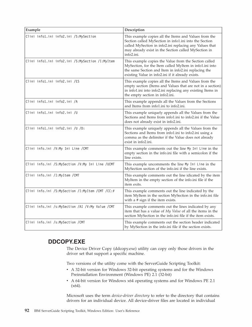
Example Description
Clini info1.ini info2.ini /S:MySection This example copies all the Items and Values from theSection called MySection in info1.ini into the Sectioncalled MySection in info2.ini replacing any Values thatmay already exist in the Section called MySection ininfo2.ini.
Clini info1.ini info2.ini /S:MySection /I:MyItem This example copies the Value from the Section calledMySection, for the Item called MyItem in info1.ini intothe same Section and Item in info2.ini replacing theexisting Value in info2.ini if it already exists.
Clini info1.ini info2.ini /ES This example copies all the Items and Values from theempty section (Items and Values that are not in a section)in info1.ini into info2.ini replacing any existing Items inthe empty section in info2.ini.
Clini info1.ini info2.ini /A This example appends all the Values from the Sectionsand Items from info1.ini to info2.ini.
Clini info1.ini info2.ini /U This example uniquely appends all the Values from theSections and Items from info1.ini to info2.ini if the Valuedoes not already exist in info2.ini.
Clini info1.ini info2.ini /U /D: This example uniquely appends all the Values from theSections and Items from info1.ini to info2.ini using acomma as the delimiter if the Value does not alreadyexist in info2.ini.
Clini info.ini /V:My Ini Line /CMT This example comments out the line My Ini Line in theempty section in the info.ini file with a semicolon if theline exists.
Clini info.ini /S:MySection /V:My Ini Line /UCMT This example uncomments the line My Ini Line in theMySection section of the info.ini if the line exists.
Clini info.ini /I:MyItem /CMT This example comments out the line idicated by the itemMyItem in the empty section of the info.ini file if theitem exits.
Clini info.ini /S:MySection /I:MyItem /CMT /CC:# This example comments out the line indicated by theitem MyItem in the section MySection in the info.ini filewith a # sign if the item exists.
Clini info.ini /s:MySection /AI /V:My Value /CMT This example comments out the lines indicated by anyitem that has a value of My Value of all the items in thesection MySection in the info.ini file if the item exists.
Clini info.ini /s:MySection /CMT This example comments out the section header indicatedby MySection in the info.ini file if the section exists.
DDCOPY.EXEThe Device Driver Copy (ddcopy.exe) utility can copy only those drivers in thedriver set that support a specific machine.
Two versions of the utility come with the ServerGuide Scripting Toolkit:v A 32-bit version for Windows 32-bit operating systems and for the Windows
Preinstallation Environment (Windows PE) 2.1 (32-bit)v A 64-bit version for Windows x64 operating systems and for Windows PE 2.1
(x64).
Microsoft uses the term device-driver directory to refer to the directory that containsdrivers for an individual device. All device-driver files are located in individual
92 IBM ServerGuide Scripting Toolkit, Windows Edition: User's Reference

device-driver directories that contain the files for an individual device driver. Thefollowing directories are device-driver directories:v \adaptecv \asmv \halv \ideraidv \srvraid
However, when specifying the source path for the ddcopy command, alwaysspecify the directory that contains the drvset.ini file. In this case, the sourcedirectory is the C:\w03_drv\$oem$\$1\drv directory.
When you issue a ddcopy command against a directory that contains device-driverdirectories. Ddcopy copies all of the device drivers that are specific to the specifiedmachine types and any other files located in the drv directory to the new location.
The SupportedSystems keyword in the drvset.ini file is modified to reflect the newmachine list.
The ddcopy.exe utility has the following command-line syntax:ddcopy <source_path> <destination_path> [/M:machine_types or platform_ids][/C:category] | [/V:n] [/?]
Parameter Description
source_path Defines the fully qualified path to the directory that contains thedevice-driver directories and the drvset.ini file.
destination_path Specifies the fully qualified path of the target directory for copying the devicedrivers.
/M:machine_types or platform_ids Specifies machine types or platform IDs to limit the number of drivers thatare copied. Multiple machine types or platform IDs are allowed whendelimited by commas.
/C:category Specifies the driver categories to limit the device drivers to be copied.Multiple categories can be specified using a comma as the delimiter. Ifomitted, then all the device driver categories are copied. Valid values are:
v Network
v Video
v Management
v Chipset
v Mass Storage
v Application
v Tape
v Hotfix.
This is only valid with driver sets from ServerGuide 7.4.12 or greater.
/V:n Specifies the verbose level used to report status during the deploymentprocess. Valid values for n are:
v 0 - quiet mode
v 3 - default
v 5 - maximum information
The ddcopy.exe utility returns the following values to indicate status:
Appendix B. ServerGuide Scripting Toolkit utilities and tools 93

Value Description
0 Success
1 Syntax error
2 Program error
3 Failed to copy
4 Machine type or platform ID not found
5 Destination is read-only
6 File not found
The following examples illustrate ddcopy.exe utility usage.
Example Description
ddcopy d:\drivers\$oem$\$1\drvc:\wininst\$oem$\$1\drv
Copies all the drivers from thed:\drivers\$oem$\$1\drv directoryto the c:\wininst\$oem$\$1\drvdirectory
ddcopy d:\drivers\$oem$\$1\drvc:\wininst\$oem$\$1\drv /M:8832
Copies the drivers that arespecifically for machine type 8832from the d:\drivers\$oem$\$1\drvdirectory to thec:\wininst\$oem$\$1\drv directoryand updates the supported systemsfield in the drivers' DrvInfo.ini fileand the c:\wininst\$oem$\$1\drv\drvset.ini file.
ddcopy d:\drivers\$oem$\$1\drvc:\wininst\$oem$\$1\drv /M:8832,8865
Copies the drivers for machine type8832 and machine type 8865 fromthe d:\drivers\$oem$\$1\drvdirectory to thec:\wininst\$oem$\$1\drv directoryand updates the supported systemsfield in the drivers' DrvInfo.ini fileand the c:\wininst\$oem$\$1\drv\drvset.ini file.
ddcopy d:\drivers\$oem$\$1\drv c:\mydrvs /m:8832 /c:network,video Copies the Network and Videodrivers specific to the machine type8832 from the d:\drivers\$oem$\$1\drv directory to the c:\mydrvsdirectory and updates thesupported systems field in thedrivers' DrvInfo.ini file as well asthe c:\mydrvs\drvset.ini file.
DSCAN.EXEThe Driver Scan utility can perform the following functions:v Scan a device driver or set of device drivers to determine the installation mode
(text mode, Plug and Play, or executable) and write this information to thedrvinfo.ini file that is located in each device-driver directory. The drvinfo.ini fileis used by the unattend.exe command during the installation of Windowsoperating systems.
v Create a text mode directory, copy all text mode device drivers into thatdirectory, then dynamically create a master txtsetup.oem file that contains all of
94 IBM ServerGuide Scripting Toolkit, Windows Edition: User's Reference

the unique information that is in the individual txtsetup.oem files. Knownunattended installation defects are automatically addressed.
Two versions of the utility come with the ServerGuide Scripting Toolkit:v A 32-bit version for Windows 32-bit operating systems and for the Windows
Preinstallation Environment (Windows PE) 2.1 (32-bit)v A 64-bit version for Windows x64 operating systems and for Windows PE 2.1
(x64).
Microsoft uses the term device-driver directory to refer to the directory that containsdrivers for an individual device. All device-driver files are located in individualdevice-driver directories that contain the files for an individual device driver. Thefollowing directories are device-driver directories:v \adaptecv \asmv \halv \ideraidv \srvraid
However, when specifying the source path for the ddcopy command, alwaysspecify the directory that contains the drvset.ini file. In this case, the sourcedirectory is the C:\w03_drv\$oem$\$1\drv directory.
When you issue a dscan command against a directory that contains device-driverdirectories, dscan performs its tasks against all of the subdirectories that thedirectory contains, with the exception of the drvutils directory. The drvutilsdirectory contains two utilities, Holdit.exe and Reboot.exe, that are used by theunattend utility.
The Driver Scan utility stores information in an INI file named drvinfo.ini in thedevice-driver directory, for use by the unattend.exe utility. If the drvinfo.ini filealready exists for the device driver, it is left unchanged. See “DRVINFO.INI” onpage 97 for information about the drvinfo.ini file. See “UNATTEND.EXE” on page132 for information about the unattend.exe utility.
The Driver Scan utility can also merge text mode device drivers into a singledirectory. This merges the device-driver files and the txtsetup.oem files for use inunattended installations. If the destination directory for text mode drivers alreadyexists, it is automatically deleted and recreated.
The Driver Scan utility automatically assumes that the device driver being scannedis applicable to all target servers. To make a device driver server-specific, you mustmodify the drvinfo.ini file to reflect the servers that the device driver supports.
The dscan.exe utility has the following command-line syntax:dscan <driver_path> [/S|/SS|/T[:path]] [/M:machine_type/platform_ID] [/H:filename[/OW] [/V:n] [/W:n] [/O:file_name] [/?]
Appendix B. ServerGuide Scripting Toolkit utilities and tools 95

Parameter Description
driver_path Defines the fully qualified path to the directory to scan for device drivers.Each driver is assumed to be in a separate subdirectory within this path.
If driver_path has $oem$ in the path, the Driver Scan utility creates the$oem$\textmode directory and merges the text mode device drivers.
If the /SS parameter is used, the path is assumed to be the path to a singledevice driver.
/S Specifies to scan device drivers and create drvinfo.ini files only, if necessary.Text mode device drivers are not merged when this parameter is used.
/SS Specifies to scan a single device driver and create the drvinfo.ini file only, ifnecessary. Text mode device drivers are not merged when this parameter isused.
/T[:path] Specifies to build the text mode device drivers only. Other device drivers arenot scanned, and drvinfo.ini files are not created when this parameter is used.
If path is specified, the text mode device drivers are merged to the specifiedpath. Otherwise, the driver_path parameter must have $oem$ in the path sothat the text mode device drivers are merged into the $oem$\textmodedirectory.
/M:machine_type/platform_ID Specifies a machine type, where machine_type is the machine type of the targetserver or platform ID, where platform_ID is the platform ID of the targetserver, that is used to limit merging of the text-mode device drivers. If thisparameter is not specified, all text-mode device drivers are merged. The /Tparameter is required to use this parameter.
/H:filename Specifies a fully-qualified path and file name for the hwdetect.ini file that wascreated by the hwdetect.exe utility. This will limit the merging of the textmode device drivers to only those drivers detected in the system.
/OW Overwrites the text-mode drivers without deleting and recreating thetext-mode directory. This parameter is not valid with the /S parameter or the/SS parameter.
/V:n Specifies the verbose level used to report status during the deploymentprocess. Valid values for n are:
v 0 - quiet mode
v 3 - default
v 5 - maximum information
/W:n Specifies the version of Microsoft Windows for the device drivers:
v 0 for Windows 2000
v 1 for Windows Server 2003
v 2 for Windows 2000 Professional
v 3 for Windows XP
v 4 for Windows Server 2003 x64
/O:file_name Combines the information in the DrvInfo.Ini files into a single file specifiedby the file_name value
/? Displays usage information
The dscan.exe utility returns the following values to indicate status:
Value Description
0 Success
96 IBM ServerGuide Scripting Toolkit, Windows Edition: User's Reference

Value Description
1 Syntax error
2 Program error
3 Destination is read-only
The following examples illustrate Driver Scan utility usage.
Example Description
dscan c:\insttemp\$oem$\$1\drv Scans a device-driver set in c:\insttemp\$oem$\$1\drv,creates the drvinfo.ini files for each device driver, andbuilds the text-mode directory
dscan c:\drv /S Scans a device-driver set in c:\drv and creates drvinfo.inifiles for each device driver, but does not build the textmode device drivers
dscan c:\drv\mydriver /SS Scans a single device driver in d:\drv\mydriver andcreates the drvinfo.ini file for that device driver, but doesnot build the text mode device driver
dscan c:\w2\$oem$\$1\drv /T Builds the text mode directory in c:\w2\$oem$\textmode using device drivers found inc:\w2\$oem$\$1\drv, but does not create any drvinfo.inifiles
dscan c:\drivers /T:c:\other\textmode Builds the text mode directory in c:\other\textmodeusing device drivers found in c:\drivers, but does notcreate drvinfo.ini files
DRVINFO.INIThe drvinfo.ini file contains information specific to each device driver. Theunattend.exe utility uses this information to add device-driver information to theanswer file for Windows deployment scenarios. You can create this file, or have theDriver Scan utility create it automatically.
The drvinfo.ini file contains one section, called [Driver Information], and cancontain the following valid variables:
Variable name Description
Automatically Reboots Specifies whether the executable device driver automatically restarts (reboots) thetarget server after the device-driver installation has completed. This variable is onlyvalid when Installation Mode is set to “Executable”. Valid values are True or False.The default value is False.
If an executable-device-driver installation program restarts the server and this variableis set to False, then any remaining installation procedures are not completed.
To use this variable, the drvutils directory must contain the Holdit.exe and Reboot.exeutilities.
This variable is only supported for Windows 2000.
Installation Mode Specifies the installation method for the device driver. Valid values are: Executable,Manual, PnP, or Textmode. If set to Manual, the unattend.exe utility does not installthe device driver.
Appendix B. ServerGuide Scripting Toolkit utilities and tools 97

Variable name Description
Order Before Specifies that the device driver is added to the answer file before another specifieddevice driver. This variable is valid only when Installation Mode is set to “PnP” or“Executable”. Valid values are a comma-delimited list of the names of thedevice-driver directories, or the special keyword “All”. If more than one device driverhas a value of “All”, the device drivers are installed in alphabetical order before thosethat do not have the specification.
Order After Specifies that the device driver is added to the answer file after all other devicedrivers. This variable is only valid when Installation Mode is set to “PnP” or“Executable”. The only valid value is the special keyword “All”. If more than onedevice driver has this value set to “All”, the device drivers are installed inalphabetical order after those that do not have the specification.
Parameters Defines any required command-line parameters required by the executable devicedriver. This variable is only valid when Installation Mode is set to Executable.
Path Specifies the path to the installation file. This variable has a different function,depending on the setting of the Installation Mode variable, as indicated below:
v Executable - Path specifies the path to the executable installation file
v Manual - Path variable is ignored
v PnP - Path specifies the path to the INF installation files
v Textmode - Path specifies the path to the txtsetup.oem file
PCIVenDevID Specifies the PCI Vendor ID or Device ID information used to limit the installation ofexecutable device drivers to only when the specified device is in the target server.This variable is only valid when Installation Mode is set to Executable. Entries must bein the same format as those in the txtsetup.oem file, with multiple entries delimitedby commas. For example:
PCIVenDevID = PCI\VEN_1002&DEV_5159&SUBSYS_029A1014
Reboot Required Specifies whether the executable device driver requires the target server to restart(reboot) after the installation of the device driver is completed. This variable is onlyvalid when Installation Mode is set to Executable. Valid values are True or False.
To use this variable, the drvutils directory must contain the Holdit.exe and Reboot.exeutilities.
This variable is only supported for Windows 2000.
Supported Locales Specifies the locales supported by this device driver. This value can be All, or acomma-delimited list of locales, as specified by the Localization variable in theProdSpec.ini file from the i386 directory of the applicable operating systeminstallation directory.
You cannot use both Supported Systems and Unsupported Systems in the samedrvinfo.ini file.
Supported Systems Specifies the servers supported by this device driver. This value can be All, None, ora comma-delimited list of server machine types or platform IDs
You cannot use both Supported Systems and Unsupported Systems in the samedrvinfo.ini file.
Unsupported Locales Specifies locales that are not supported by this device driver. This value must be acomma-delimited list of locales, as specified by the Localization variable in theProdSpec.ini file from the i386 directory of the applicable operating systeminstallation directory.
You cannot use both Supported Locales and Unsupported Locales in the samedrvinfo.ini file.
98 IBM ServerGuide Scripting Toolkit, Windows Edition: User's Reference

Variable name Description
Unsupported Systems Specifies servers that are not supported by this device driver. This value must be acomma-delimited list of server machine types or platform IDs.
You cannot use both Supported Systems and Unsupported Systems in the samedrvinfo.ini file.
The following examples illustrate drvinfo.ini file contents.
Example Description
[Driver Information]Installation Mode=PnPPath=Parameters=Automatically Reboots=Reboot Required=PCIVenDevID=Order Before=Supported Systems=All;Unsupported Systems=Supported Locales=;Unsupported Systems=
Supports a plug-and-play device driver with INF files inthe root of the device driver directory, and supports alltarget servers
[Driver Information]Installation Mode=PnPPath=win2000Parameters=Automatically Reboots=Reboot Required=PCIVenDevID=Order Before=Supported Systems=8673,8679,8687;Unsupported Systems=Supported Locales=;Unsupported Systems=
Supports a plug-and-play device driver with INF files inthe win2000 directory in the root of the device driverdirectory, and only supports target servers with machinetypes 8673, 8679, and 8687
[Driver Information]Installation Mode=PnPPath=win2000Parameters=Automatically Reboots=Reboot Required=PCIVenDevID=Order Before=AllSupported Systems=8673,8679,8687;Unsupported Systems=Supported Locales=;Unsupported Systems=
Supports a plug-and-play device driver that must beinstalled before any other plug-and-play device driver,with INF files in the win2000 directory in the root of thedevice driver directory, and supports only target serverswith machine types 8673, 8679, and 8687
[Driver Information]Installation Mode=ExecutablePath=win2000\setup.exeParameters=-QAutomatically Reboots=FalseReboot Required=TruePCIVenDevID=PCI\VEN_1002&DEV_5159&SUBSYS_1014029AOrder Before=All;Supported Systems=Unsupported Systems=8687Supported Locales=;Unsupported Systems=
Supports an executable device-driver installation usingsetup.exe, with a -Q parameter, in the win2000 directoryin the root of the device driver directory, and supportsall target servers (except those of machine type 8687) thathave a device installed matching the specifiedVendor/Device ID.
Appendix B. ServerGuide Scripting Toolkit utilities and tools 99

HWDETECT.EXEHWDETECT is used to perform basic hardware detection functions that aretypically obtained using SMBIOS and a PCI scan. This utility contains options thatcan be used to dump all of the hardware information to an output file, or it can beused to query hardware information and return values that set the errorlevelenvironment variable or the return code in Windows PE.
HWDETECT has basic hardware scan functions, and more complex PCI devicedetection options. The basic hardware scan functions can only be used singularly.The PCI device detection functions may be used in combination with each other toproduce a query based on multiple restrictions.You can only use the hwdetect.exeutility basic hardware scan functions one at a time. The PCI-device detectionfunctions can be combined or used more than once on the same command line.
Two versions of HWDETECT.EXE are provided with the ServerGuide ScriptingToolkit:v A 32-bit version for use with Windows Server 2003 and Windows PE 2.1 (32-bit)v An x64 version for use with Windows Server 2003 x64 and Windows PE 2.1
(x64)
The hwdetect.exe utility has the following command-line syntax:hwdetect [/s|/p|/i|/m:type] [/vid:vendor_id] [/did:device_id] [/svid:sub_vendor_id][/sdid:sub_device_id] [bn:bus_number] [/dn:device_number] [/add:num]
Parameter Description
Basic hardware scan functions
/s Determines if the target server is an IBM eServer or IBM eServer xSeriesserver. The return values are:
v 0 for an IBM eServer or IBM eServer xSeries server
v 1 for a non-IBM eServer or IBM eServer xSeries server
/p Displays all hardware information for the target server in a variable=valueformat. The return value is 0 when successful.
You can use the > output-redirect option to save the output to an output file.For example, hwdetect /p > filename
/i Displays all hardware information for the target server in an INI-file format.The return value is 0 when successful.
You can use the > output-redirect option to save the output to an output file.
/m:type Compares the machine type of the target xSeries server to the specifiedmachine type, type. The return values are:
v 0 when the machine types are different or no basis for comparison exists
v 1 when the machine types match
Parameter Description
PCI-device detection functions
/vid:vendor_id Determines whether there is a PCI adapter in the target server that matchesthe specified vendor ID, where vendor_id is a hexadecimal value. The returnvalue is the number of matching adapters in the target server, or 0 if there areno matches.
100 IBM ServerGuide Scripting Toolkit, Windows Edition: User's Reference

Parameter Description
/did:device_id Determines whether there is a PCI adapter in the target server that matchesthe specified device ID, where device_id is a hexadecimal value. The returnvalue is the number of matching adapters in the target server, or 0 if there areno matches.
/svid:sub_vendor_id Determines whether there is a PCI adapter in the target server that matchesthe specified sub-vendor ID, where subvendor_id is a hexadecimal value. Thereturn value is the number of matching adapters in the target server, or 0 ifthere are no matches.
/sdid:sub_device_id Determines whether there is a PCI adapter in the target server that matchesthe specified sub-device ID, where subdevice_id is a hexadecimal value. Thereturn value is the number of matching adapters in the target server, or 0 ifthere are no matches.
/bn:bus_number Causes the PCI scan to begin at the specified bus number, instead of startingat bus 0, by default. This parameter is only valid when more than one /vid,/did, /svid, or /sdid parameter is specified on the command line.
/dn:device_number Causes the PCI scan to begin at the specified device number, instead ofstarting at device number 0, by default. This parameter is only valid whenthe /bn parameter is specified on the command line.
/add:num Adds an integer number, num, to the return value before exiting. This isuseful to obtain a sum of different PCI adapters, with different PCI IDs, in atarget server. The return value is the resultant sum of all other return valuesplus num.
The following examples illustrate hwdetect.exe utility usage.
Example Description
hwdetect /sif errorlevel 1 goto NONIBMif errorlevel 0 goto IBM
:NONIBMrem Perform non-IBM equipment specific steps heregoto FINISH
:IBMrem Perform IBM equipment specific steps here
:FINISH
Determines if the target server is an IBM server or not,and branches accordingly to perform equipment-specificsteps
hwdetect /m:8676if errorlevel 1 goto 8676
hwdetect /m:8669if errorlevel 1 goto 8669
echo System not supported!goto done
:8676call 8676.batgoto done
:8669call 8669.batgoto done
:done
Determines if the target server is either a machine type8676 or machine type 8669 server, and branchesaccordingly to call a system-specific batch file or displaysa message of non-support for other machine types
Appendix B. ServerGuide Scripting Toolkit utilities and tools 101

Example Description
hwdetect /i>hwdetect.outclini hwdetect.out /S:CI /I:Vendor_ID.0 /E:VendorCLIniSet.bat
Creates an output file that lists the hardwareconfiguration for the target server, so that the clini.exeutility can search for a specific PCI adapter from avendor and set en environment variable accordingly
hwdetect /vid:0x9005 /did:0x0250if errorlevel 1 call 6Mstuff.bat
Determines if there is at least one IBM ServeRAID6i/6i+/6M PCI adapter in the target server, and calls abatch file to process adapter-specific tasks
hwdetect /vid:0x9005 /did:0x0250if errorlevel 0 set TOTAL=0if errorlevel 1 set TOTAL=1if errorlevel 2 set TOTAL=2if errorlevel 3 set TOTAL=3
hwdetect /add:%TOTAL% /vid:0x1014 /did:0x01BDif errorlevel 0 set TOTAL=0if errorlevel 1 set TOTAL=1if errorlevel 2 set TOTAL=2if errorlevel 3 set TOTAL=3if errorlevel 4 set TOTAL=4if errorlevel 5 set TOTAL=5if errorlevel 6 set TOTAL=6
echo There are %TOTAL% IBM ServeRAID adapters inthis system
Determines the total number of IBM ServeRAID adaptersin the target server, assuming there are no more thanthree of each type: IBM ServeRAID 4, IBM ServeRAID 5,and IBM ServeRAID 6/6i/6M
hwdetect /i>hwdetect.out Displays hardware configuration information about thetarget server. The >hwdetect.out parameter is a Windowsoutput-redirect option that causes the output from thehwdetect.exe utility to be saved in the specified file.
Below is an example of the hwdetect.out file that the last example might create:[System]Machine_Type=8674Model_Number=42XSerial_Number=78Z9506Product_Name=eserver xSeries 330BIOS_version=1.04BIOS_Build_Level=EME112ABIOS_DATE=06/28/2002BIOS_Manufacturer=IBMBIOS_Language=USNumber_Of_Enclosures=1Enclosure_Type.0=23Processor_Slots=2Active_Processors=1Processor_Family.0=17Processor_Speed_MHz.0=1400Processor_X64 = TRUETotal_Enabled_Memory_Mb=256ROM_Diagnostics_Build_Level=EME112AISMP_Build_Level=BR8T30ARSA_Build_Level=GEE834ASystem_UUID = 8030E01060F010B010605090D0A020F0Blade_Chassis_UUID = 0F020A0D0900F00F020A0D0900F00F02Blade_Slot = 02
[PCI]Total_Number_Devices=10Bus_Number.0=0Device_Number.0=1Function_Number.0=0
102 IBM ServerGuide Scripting Toolkit, Windows Edition: User's Reference

Class_Code.0=0000Revision.0=0Header_Type.0=0Vendor_ID.0=5333Device_ID.0=8A22Subvendor_ID.0=1014Subdevice_ID.0=01C5Bus_Number.1=0Device_Number.1=2Function_Number.1=0Class_Code.1=0000Revision.1=0Header_Type.1=0Vendor_ID.1=8086Device_ID.1=1229Subvendor_ID.1=1014Subdevice_ID.1=105C
Running “hwdetect /p” produces the same output with the exception that thesection names are tacked onto the beginning of each keyword:System_Machine_Type = 8674System_Model_Number = 42XSystem_Serial_Number = 78Z9506...PCI_Bus_Number.0 = 0PCI_Device_Number.0 = 1...
Notes:
1. The BIOS_DATE value is listed in mm/dd/yyyy format.2. The Enclosure_Type.0=23 is based on SMBIOS 2.3 spec. 23 = Main
chassis.3. There is an entry for Processor_Family and Processor_Speed_MHz for
each microprocessor in the server.4. The ROM_Diagnostics_Build_Level is empty for servers that do not
support ROM diagnostics.5. PCI devices are listed in the order they are scanned.6. PCI devices are listed in the Value.n format, where Value is the variable
name and n is the nth PCI device scanned.7. The header_type field is not available for versions of hwdetect running
on Windows 32 or 64-bit operating systems.8. The vendor, device, subvendor, and subdevice values are in
hexadecimal notation.
INVRAID.EXEThis program can be used to dump all of the RAID controller configurationinformation to an output file. INVRAID supports the following RAID controllers:v ServeRAID-4Hv ServeRAID-4Mxv ServeRAID-4Lxv ServeRAID-5iv ServeRAID-6Mv ServeRAID-6i/6i+v ServeRAID-7kv ServeRAID-7t
Appendix B. ServerGuide Scripting Toolkit utilities and tools 103

v ServeRAID-7e SATAv ServeRAID-7e SCSIv ServeRAID-8iv ServeRAID-8kv ServeRAID-8e SATAv ServeRAID-8e SASv ServeRAID-8sv ServeRAID-BR10iv ServeRAID-BR10iev ServeRAID-BR10ilv ServeRAID-BR10il V2v ServeRAID-M1015v ServeRAID-M1015-R5v ServeRAID-M5014v ServeRAID-M5015v ServeRAID-MR10iv ServeRAID-MR10iev ServeRAID-MR10ilv ServeRAID-MR10isv ServeRAID-MR10kv ServeRAID-MR10Mv LSI Integrated SCSI-RAID controllerv LSI Integrated SAS-RAID controller (1064/1064E/1068)v LSI IDEal RAID controllerv LSI MegaRAID SAS controllerv LSI SAS 1078 IR controllerv IBM SAS HBA 1068Ev IBM 3Gb SAS HBA v2
Environment requirements
Because INVRAID works by scripting the interfaces of other RAID-configurationutilities, the following utilities must be located in the system search path.
Adapter Windows PE Utility
ServeRAID-4H, 4Mx, 4Lx, 5i, 6M, 6i, 6i+, 7k IPSSEND
ServeRAID-7t, 8i, 8k, 8k-l, 8s ARCCONF
ServeRAID-7e SATA, 7e SCSI, 8e SAS, 8eSATA
HRCONF
Integrated SCSI with RAID capabilities,integrated SAS with RAID capabilities, LSISAS 1078 IR, ServeRAID-BR10i, BR10ie,BR10il, BR10il V2, IBM SAS HBA 1068E,IBM 3Gb SAS HBA v2
CFGGEN
IDE RAID HYPERWIN
ServerRAID-8e SATA HRCONF
104 IBM ServerGuide Scripting Toolkit, Windows Edition: User's Reference

Adapter Windows PE Utility
MegaRAID SAS, ServeRAID-MR10i, MR10ie,MR10k, MR10M, M1015, M1015–R5, M5014,M5015
MEGACLI
Usageinvraid [/I | /P] /L /F
Table 18. INVRAID parameters
Parameter Description
/I Displays information about the all hostadapters in the system in an INI-file format.
/P Dumps information about all host adaptersin a system in a keyword=value format.
/L Specifies the light version of the RAIDutility.
/F Dumps information about all host adaptersin the system to a file.
Return values
Table 19 lists the values returned by INVRAID.
Table 19. Values returned by INVRAID
Return Value Description
0 Success
1 Syntax Error
2 Program Error
Examples
To dump the information about all RAID controllers in a system to a file in INI fileformat with the name myraid.ini, use the /I parameter as shown here:invraid.exe /i /f:myraid.ini
Returns:[System]Machine_Type = 7977Serial_Number = KOKN689Total_Number_Of_Controllers = 2
[RAIDController.1]Model = ServeRAID-8k-lBIOSVersion = 5.2-0 (15412)FirmwareVersion = 5.2-0 (15412)DriverVersion = 5.2-0 (15317)RebuildRate = HIGHStripeSize = 256ReadAhead = ADAPTIVEPCI = 9005:0286:FFFF:FFFF
[RAIDController.1.Array]Total_Number_Of_Arrays = 1
Appendix B. ServerGuide Scripting Toolkit utilities and tools 105

ID.1 = AMembers.1 = 1,2,3,4
[RAIDController.1.Hotspares]Total_Number_Of_Hotspares = 0
[RAIDController.1.Logical]Total_Number_Of_Logicals = 1Array.1 = ASize.1 = 279800Raid_Level.1 = 10WriteCache.1 = AUTO
[RAIDController.1.Physical]Total_Number_Of_Physicals = 4Channel.1 = 1ID.1 = 0Size.1 = 140013Type.1 = SASSerial_Number.1 = JDX2JN8KChannel.2 = 1ID.2 = 1Size.2 = 140013Type.2 = SASSerial_Number.2 = Q5902T4NChannel.3 = 1ID.3 = 2Size.3 = 140013Type.3 = SASSerial_Number.3 = Q5902TPAChannel.4 = 1ID.4 = 3Size.4 = 140013Type.4 = SASSerial_Number.4 = Q5902TS8
[RAIDController.2]Model = ServeRAID-8sBIOSVersion = 5.2-0 (15411)FirmwareVersion = 5.2-0 (15411)DriverVersion = 5.2-0 (15317)PCI = 9005:0285:1014:034D
[RAIDController.2.Array]Total_Number_Of_Arrays = 0
[RAIDController.2.Hotspares]Total_Number_Of_Hotspares = 0
[RAIDController.2.Logical]Total_Number_Of_Logicals = 0
[RAIDController.2.Physical]Total_Number_Of_Physicals = 0
Using the /P parameter returns the same information, but the section title from theproperties file is shown for each value:invraid /p > myfile.ini
Returns:System_Machine_Type = 7977System_Serial_Number = KOKN689
RAIDController.1.Model = ServeRAID-8k-lRAIDController.1.BIOSVersion = 5.2-0 (15412)
106 IBM ServerGuide Scripting Toolkit, Windows Edition: User's Reference

RAIDController.1.FirmwareVersion = 5.2-0 (15412)RAIDController.1.DriverVersion = 5.2-0 (15317)RAIDController.1.RebuildRate = HIGHRAIDController.1.StripeSize = 256RAIDController.1.ReadAhead = ADAPTIVERAIDController.1.PCI = 9005:0286:FFFF:FFFFRAIDController.1.Array.ID.1 = ARAIDController.1.Array.Members.1 = 1,2,3,4RAIDController.1.Logical.Array.1 = ARAIDController.1.Logical.Size.1 = 279800RAIDController.1.Logical.Raid_Level.1 = 10RAIDController.1.Logical.WriteCache.1 = AUTORAIDController.1.Physical.Channel.1 = 1RAIDController.1.Physical.ID.1 = 0RAIDController.1.Physical.Size.1 = 140013RAIDController.1.Physical.Type.1 = SASRAIDController.1.Physical.Serial_Number.1 = JDX2JN8KRAIDController.1.Physical.Channel.2 = 1RAIDController.1.Physical.ID.2 = 1RAIDController.1.Physical.Size.2 = 140013RAIDController.1.Physical.Type.2 = SASRAIDController.1.Physical.Serial_Number.2 = Q5902T4NRAIDController.1.Physical.Channel.3 = 1RAIDController.1.Physical.ID.3 = 2RAIDController.1.Physical.Size.3 = 140013RAIDController.1.Physical.Type.3 = SASRAIDController.1.Physical.Serial_Number.3 = Q5902TPARAIDController.1.Physical.Channel.4 = 1RAIDController.1.Physical.ID.4 = 3RAIDController.1.Physical.Size.4 = 140013RAIDController.1.Physical.Type.4 = SASRAIDController.1.Physical.Serial_Number.4 = Q5902TS8RAIDController.2.Model = ServeRAID-8sRAIDController.2.BIOSVersion = 5.2-0 (15411)RAIDController.2.FirmwareVersion = 5.2-0 (15411)RAIDController.2.DriverVersion = 5.2-0 (15317)RAIDController.2.PCI = 9005:0285:1014:034D
LEcho.EXEThe Logging Echo utility can perform the following functions:v Write a message to the displayv Write a message to a log filev Set the system errorlevel with a specific codev Display a message to the screen while pausing or running a timer for a discreet
amount of time
The ServerGuide Scripting Toolkit provides 32 and 64 bit versions of LEcho.
In order for LEcho.exe to write a message to a log file, you must set theenvironment variable LECHO_LOG to a fully qualified path and filename using acommand similar to the following:set LECHO_LOG=C:\SGTKWinPE\Lecholog.txt
LEcho.exe checks the number of characters on the command line against thecurrent command line limits of 8000 characters for the Windows environment. Amessage is displayed if the characters exceed the limit.
Usage
The LEcho.exe utility has the following command-line syntax:
Appendix B. ServerGuide Scripting Toolkit utilities and tools 107

The LEcho.exe utility has the following command-line syntax:
LEcho [message] [/F] [/R:n][/E:n] [/P] [/P:n] [/T:n][/SC] [/SN] [/N] [/LO] [/DO] [/?]
Parameter Description
message The message to display to the screen or logfile.
/F Formats the message using the followingvariables:
v %d or %nd formats the system date. Theformat is indicated by n:
– 0 = Sun 12/31/2006 (Default)
– 1 = Sunday, December 31, 2006
– 2 = Sun, Dec 31, 2006
– 3 = Dec 31, 2006
– 4 = 12-31-2006
– 5 = 12/31/2006
– 6 = 2006-12-31
– 7 = 2006-Dec-31
– 8 = 2006-December-31
– 9 = 20061231
v %t or %nt formats the system time. Theformat is indicated by n.
– 0 = 16:12:13 (Default)
– 1 = 04:12:13 PM
v \a sets an alert (bell)
v \b - backspace
v \f - form feed
v \n - newline
v \r - carriage return
v \t - horizontal tab
/R:n Repeats the message n times.
/E:n Displays the error message and sets thesystem errorlevel to n.
/P Pauses until a key is pressed.
/P:n Pauses for n seconds or until a key ispressed
/T:n Initiates a timer for n seconds. This timercannot be ended prematurely.
/SC Suppresses the output of the countdowntimer.
/SN Suppresses the newline character.
/N Creates a new, blank log file. If the log filealready exists, it is overwritten.
/LO Writes the message to the log file only.
/DO Writes the message only to the display.
/? Display a help message containing theapplication syntax.
108 IBM ServerGuide Scripting Toolkit, Windows Edition: User's Reference

Return codes
The LEcho.exe utility returns the following values to indicate status:
Value Description
0 Success or true
1 Syntax error
5 Cannot write to log file.
100 False
255 Program error
Examples
The following examples illustrate Logging Echo utility usage.
Example Description
LEcho Sends a blank line to the display, and the logfile if LECHO_LOG is set.
LEcho “My Message” Sends the text “My Message” to the displayand to the log file if LECHO_LOG is set.
LEcho /T Displays a message indicating the currentsystem time to the display and to the log fileif LECHO_LOG is set.
LEcho “My Message” /T Sends the text “13:55:24 – My Message” tothe display and the log file if LECHO_LOGis set, 13:55:24 indicating the current systemtime.
LEcho “My Message” /T /DO Sends the text “13:55:24 – My Message” tothe display only. 13:55:24 indicating thecurrent system time.
LEcho “My Message” /E:200 Sends the text “My Message” to the displayand the log file if LECHO_LOG is set, andthen sets the system error level to 200.
LEcho /E:155 Sets the system error level to 155. No text isdisplayed or logged.
LEcho “New Log File” /N /LO Creates a new log file from LECHO_LOG. Ifa log file already exists, it is deleted and anew one is created. It then sends the text“New Log File” to the new log file only. Notext is displayed to the screen.
LEcho “%d\t%t – My Message” /F Sends the text “Sun 12-31-2006 16:12:13 – MyMessage” to the screen and log file ifLECHO_LOG is set.
LEcho “Pausing for 30 seconds.” /P:30 Sends the text “Pausing for 30 seconds,” anda countdown timer beginning at 30. Thiscountdown can be bypassed by pressing anykey.
Appendix B. ServerGuide Scripting Toolkit utilities and tools 109

Example Description
LEcho “Running a 30 second timer.” /T:30/SC /SO
Sends the text “Running a 30 second timer.”to the screen only, and returns control to theenvironment after 30 seconds. No timer isdisplayed.
PRAID.EXEPRAID is a scriptable executable program that offers a single user interface forboth configuring and replicating all RAID controllers supported by theServerGuide Scripting Toolkit. PRAID works with both the 32 and 64 bit versionsof the Windows Preinstallation Environment.
PRAID has three modes of operation:v Deploy mode – for scripted configuration of RAID controllers.v Capture mode – for replicating RAID controller settings.v Restore-defaults mode – for resetting RAID controllers to factory-default
settings only.
Deploy mode
Used in Deploy mode, PRAID offers the following features:v Configures all RAID controllers in a server with a single call to the program.v Automatically resets all RAID controllers to factory-default settings before
configuring.v Uses customizable logic to decide which configuration (policy) is applied to a
server based on system hardware. The logic can involve:– Machine type of the server– Serial number of the server– Number of drives connected to the RAID controller– RAID controller type– Controller number (order) of the RAID controller
v Can be highly customized for specific RAID configurations, or highlygeneralized to handle many different RAID configurations.
v Provides a default or AUTO mode for automatically creating arrays and logicaldrives using default settings. This mode requires no knowledge of the number,size, or location of the drives connected to the RAID controllers.
v Automatically applies default values for any RAID configuration parameters thatyou do not supply. You supploy only the parameters that you want to change.
v Default values for each configuration parameter are equivalent to the defaultsettings of the ServeRAID Manager express configuration method, whereapplicable.
v Allows up to 50 policies for configuring RAID controllers to be specified in asingle policies file.
Note:
When using PRAID in Deploy mode, the /r parameter is required.
110 IBM ServerGuide Scripting Toolkit, Windows Edition: User's Reference

To delete RAID configuration on all controllers, specify /r. To delete RAIDconfiguration on a specific controller, specify /r# where # is the controllernumber.
For example, praid /f:policiy.ini /r /y.
Capture mode
Used in Capture mode, PRAID offers the following features:v Captures the RAID configurations of all supported controllers to a text file, the
policies file, with a common format.v Captured RAID configurations can be immediately used with PRAID in deploy
mode to easily replicate the RAID configuration to many servers.v Allows customizable logic when saving the captured parameters to determine
when each captured configuration should be deployed.v Saves useful information about each captured configuration, including the
system machine type, date, and time when the configuration was captured.v Allows you to edit any RAID configurations that you capture before deploying
them to other systems.
Restore-defaults mode
Used in Restore-defaults mode, PRAID offers the following features:v Deletes all arrays and logical drives on all RAID controllers.v Sets other RAID controller settings back to factory defaults.
Environment requirementsThe PRAID utility supports the following RAID controllers:v For 32–bit Windows PE only:
– ServeRAID-4H– ServeRAID-4Mx– ServeRAID-4Lx– ServeRAID-5i– ServeRAID-6M– ServeRAID-6i/6i+– ServeRAID-7k
v For both the 32 and 64 bit versions of Windows PE:– ServeRAID-6M– ServeRAID-7t– ServeRAID-8i– ServeRAID-8k– ServeRAID-8k-l– ServeRAID-8s– ServeRAID-10k– ServeRAID-10M– ServeRAID-B5015– ServeRAID-BR9i– ServeRAID-BR10i– ServeRAID-BR10ie– ServeRAID-BR10il– ServeRAID-M5014– ServeRAID-M5015– ServeRAID-M5025– ServeRAID-MR10i
Appendix B. ServerGuide Scripting Toolkit utilities and tools 111

– ServeRAID-MR10il– ServeRAID-MR10is– ServeRAID-MR1015– ServeRAID-MR1015–R5– LSI SCSI (1020/1030)– LSI SAS (1064/1064E/1068/1078)
PRAID works by scripting the interfaces of other RAID-configuration utilities. Inorder to accomplish this the following utilities must be in the system search path:
Adapter Utility
ServeRAID 6M IPSSEND
ServeRAID-7t, 8i, 8k, 8k-l, 8s ARCCONF
LSI-SCSI 1020/1030, LSI-SAS 1064/1064E,LSI-SAS 1068, LSI-SAS 1078, ServeRAIDBR9i, BR10i, BR10ie, BR10il
CFGGEN
MegaRAID SAS, ServeRAID-M5014, M5015,M5025, MR10i,, MR10ie,MR10il, MR10is,MR10k, MR10M, MR1015, MR1015–R5
MEGACLI
ServeRAID-B5015 BRCLI
UsageEach of the modes supported by PRAID requires a specific syntax, but they allshare some common parameters, described in Table 20.
Table 20. PRAID parameters common to multiple modes
Parameter Description Usage
/r:n
Restore-defaults mode
Restores the RAID controller with thecontroller number specified by n tofactory-default settings and then returnsimmediately. No RAID configuration isdone if you use this parameter.
If no value is specified for the controllernumber, all RAID controllers are resetto factory-default settings.
Used alone, the parameter providesRestore-defaults mode. You must usethis parameter in conjunction withDeploy mode parameters to resetcontrollers to the factory defaultsettings before deploying a newconfiguration.
praid /r
Restores all controllers to factory-defaultsettings.
praid /r:3
Restores controller three to factory-defaultsettings. No other controllers are affected.
PRAID /f:policies.ini /r /v:5 /e1
Configures the RAID controllers in thesystem using the policies file policies.ini,sets the verbose mode to maximum, andreturns an error code if there were nomatching policies for any controllers.
112 IBM ServerGuide Scripting Toolkit, Windows Edition: User's Reference

Table 20. PRAID parameters common to multiple modes (continued)
Parameter Description Usage
/f:policies_file
Specifies the policy file
The policy file name. This parameter isrequired for capture mode, and fordeploy mode unless the /d parameteris used.
In deploy mode, this points to thepolicies that you would like PRAID touse when configuring the RAIDcontrollers. You cannot use thisparameter with the /d parameter.
In capture mode, this points to the filewhere you would like the capturedconfigurations to be written. If the filedoes not exist, PRAID will create it. Ifthe file does exist, PRAID will appendto the end of it.
The /f parameter is valid in deploy andcapture modes.
praid /f:myfile.ini
Uses the policies file, myfile.ini, to configureall RAID controllers.
praid /c /f:myfile.ini
Captures the RAID configuration of allcontrollers to the policy file, myfile.ini.
/y
Suppresses prompting
Suppresses the confirmation prompt.This parameter is optional.
If you select the /y paramter, PRAIDdoes not prompt you before resettingcontrollers to factory-default settings.PRAID always resets all controllers tofactory-default settings beforeconfiguring them.
If you do not supply this parameter,PRAID will pause to warn you beforeresetting the RAID controllers tofactory-default settings.
The /y parameter is valid in deployand restore-defaults modes.
This parameter is optional.
praid /f:myfile.ini /y
Uses the policies in myfile.ini to configure theRAID controllers and does not prompt beforeresetting all controllers to factory-defaultsettings.
/e2
Error code 2 if nosupported controllersfound
Returns an error code of 2 if there wereno supported RAID controllers found inthe system.
By default, PRAID does not return anerror if no controllers are found in thesystem.
This parameter is valid in all modes.
This parameter is optional.
praid /c /f:c:\myfile.ini /e2
Captures the RAID configuration of all RAIDcontrollers to c:\myfile.ini, and returns anerror if no controllers are found in thesystem.
Appendix B. ServerGuide Scripting Toolkit utilities and tools 113

Table 20. PRAID parameters common to multiple modes (continued)
Parameter Description Usage
/e3
Error code 3 if nosupported drives found
Returns an error code of 3 if at leastone controller was found with nodrives attached.
By default, PRAID does not return anerror if no drives are attached to aRAID controller.
This parameter is valid in any mode.
This parameter is optional.
praid /d /e3
Configures all RAID controllers with defaultsettings and returns an error if one or morecontrollers has no drives attached.
/v:n
Verbose level
Sets the verbosity level, where n is:
v 0 - quiet
v 3 - default
v 5 - maximum
This parameter is valid in any mode.
This parameter is optional.to ‘max’.
praid /d /v:5
Configures all RAID controllers with defaultsettings, and sets the verbose level
Deploy mode
The syntax for Deploy mode is:PRAID.EXE /f:policies /r /d /p:path /e1 /e2 /e3/v:n /y /b
The parameters unique to Deploy mode are described below.
Table 21. PRAID Deploy mode parameters
Parameter Description Usage
/d
Configure with defaults
Configure all controllers in thesystem using default settings insteadof using a policies file. The defaultsettings used are the same as thedefault settings for the policies file.
You cannot use this parameter withthe /f parameter. See Table 25 onpage 127 for the default values thatwill be assigned for each RAIDcontroller based on the number ofdrives attached to the controller.
This parameter is required unless the/f parameter is specified.
praid /d /r
Configures all RAID controllers inthe system using default settings.
/e1
Error if no policy found
Returns an error code of 1 if one ormore controllers are not configureddue to the fact that there was nopolicy found to configure them
This parameter is optional.
praid /f:policy.ini /r /e1
Configures all RAID controllers usingthe policies file, policy.ini, andreturns an error if no matching policywas found.
114 IBM ServerGuide Scripting Toolkit, Windows Edition: User's Reference

Capture mode
The syntax for Capture mode is:PRAID.EXE /c[:p] /f:policies /e2 /e3 /v:n
The parameters unique to Capture mode are described below.
Table 22. Capture mode parameters
Parameter Description Usage
/c[:p]
Capture mode
Indicates capture mode. The :pportion is optional. If you do notinclude the optional portion, then :pwill assume the default value: “t,d”.
You can use :p to provide a list ofparameters describing the AppliesTothat should be created whencapturing the parameters to a policy.See “AppliesTo.n” on page 119.
:p is a list containing any of thefollowing:
v t – Use the type of the RAIDcontroller in the AppliesTo.1 entryfor the policy.
v c – Use the controller number (scanorder relative to all other RAIDcontrollers in the system) in theAppliesTo.1 entry for the policy.
v d – Use the number of drivesconnected to the RAID controllerin the AppliesTo.1 entry for thepolicy.
Note: You must specify the name ofthe policies file using the /fparameter when using the /cparameter.
The policy or policies created areappended to the end of the file if thefile exists. If the file does not exist, anew file is created. If there aremultiple RAID controllers in thesystem, their configurations areplaced in the file in scan order.
praid /c:m,t /f:myfile.ini
Captures the configuration of allRAID controllers to myfile.ini usingthe machine type of the server andthe RAID controller type as theAppliesTo.1 entry.
Restore-defaults mode
The syntax for Restore-defaults mode is:PRAID /r:n /e2 /v:n /y
Usage examplesDeploy mode examplesPRAID /r /d /y
v Configures all RAID controllers in the system using default settings.v Does not prompt before setting controllers to factory-default settings.
Appendix B. ServerGuide Scripting Toolkit utilities and tools 115

v Performs drive synchronization without prompting, when required.
This example is useful for unattended scripted installations.PRAID /f:policies.ini /r /v:5 /e1
v Configures the RAID controllers in the system using the policies file: policies.ini.v Sets the verbose mode to maximum.v Returns an error code if there were no matching policies for one or more
controllers
Capture mode examplesPRAID /c /f:c:\mydata\policies.ini
Captures the configuration of all RAID controllers into the file:C:\mydata\policies.ini.PRAID /c:m,t /f:policies.ini
v Captures the configuration of all RAID controllers into the file: policies.ini.v Uses the system machine type and RAID controller type as the AppliesTo.1 entry
in the policies file for each captured configuration.
Restore-defaults mode examplesPRAID /r /v:0 /y
v Restores all RAID controllers to factory-default settings.v Operates in silent mode, no messages are printed to the screen.v Does not prompt the user before restoring factory-default settings.
Return codesv 0 - Success.v 1 - Execution was successful, but the /e1 parameter was supplied and at least
one controller was not configured because there was no matching policy.v 2 - Execution was successful, but the /e2 parameter was supplied and no
controllers were found in the system.v 3 - Execution was successful, but the /e3 parameter was supplied and at least
one controller was not configured because no drives were attached.v 4 - Syntax error on the command line.v 5 - Syntax error in the policies file or the policy file could not be opened.v 6 - Reservedv 7 - Error resetting a controller to the default settings.v 8 - Error gathering information about a controller.v 9 - Error in the policy file.v 10 - Error during processing.v 11 - Error during deployment.
Policies fileWhen used in configure mode, the policies file directs how PRAID configures theRAID controllers in a system using keywords and values that can be customizedby the user. In capture mode, PRAID creates or appends to the end of a policiesfile the parameters that can configure other RAID controllers identically to the onesin the current system.
A policies file can be created using any of the following methods:
116 IBM ServerGuide Scripting Toolkit, Windows Edition: User's Reference

1. Run PRAID in capture mode to create a policies file from an already-configuredRAID controller.
2. Use one of the example policies files provided with the ServerGuide ScriptingToolkit, and customize it to configure your RAID controllers.
3. Use an ASCII text editor to create a new policies file.
The policies file is an ASCII text file that is organized in INI-file format. EachINI-file section name indicates the start of a new policy for configuring RAIDcontrollers.
The policies file must contain one or more uniquely-named sections using theformat [Policy.name] where name is a unique user-assigned name that is used toidentify the policy. Name can be any combination of letters, numbers, underscores,periods, or dashes.
Some examples of legal section names are: [Policy.1], [Policy.mypolicy], and[Policy.My-RAID5-config]. Each section in the policies file represents a singlepolicy for configuring RAID controllers. You can have up to 50 policies in a singlepolicies file.
How PRAID selects a policy: Each section in the policies file represents a singlepolicy for configuring the RAID controllers. In configure mode, each RAIDcontroller is configured using a single policy, but a single policy can be used toconfigure multiple controllers. Each policy in a policies file contains one or moreAppliesTo.n entries, where n is the number of the AppliesTo parameter within thepolicy. This entry is required in each section, so every section must contain at leastan AppliesTo.1 entry. See “Policies file parameters” for a full description of theAppliesTo.n entry.
These entries are followed by a list of hardware parameters including machinetype, number of drives connected to the RAID controller, and scan order, that areevaluated against the current system hardware. If all of the hardware parametersof an AppliesTo.n entry match the hardware being evaluated, this policy is used toconfigure the hardware. For each policy in the policies file, the AppliesTo.n entriesfor that policy are evaluated in order starting with AppliesTo.1. If none of theAppliesTo.n entries match the current hardware then the policy is not applied andthe AppliesTo.n entries in the next policy are evaluated. This continues until eithera match is found or no more policies exist in the file. If the end of the file isreached without a match then the controller is not configured. Because the policiesare evaluated in order, you should place more specific policies at the beginning ofthe policies file.
Policies file parameters: This section describes the parameters used in the policiesfile. The Policy.name header and AppliesTo.1 entry are the only parametersrequired. All values are case-insensitive.
If you do not specify a value for any of the other parameters, they will be assignedtheir default value when applicable. If a parameter is not valid for a RAIDcontroller, it will be ignored.
In addition to this reference, the ServerGuide Scripting Toolkit also provides twoexample policies files that you can modify for your own use.v RAID1-5.ini Creates a RAID-1 array using the first two drives, and a RAID-5
array using the remaining drives. Valid for ServeRAID-4H, 4Mx, 4Lx, 5i, 6i, 6M,6i+, 7k, 8i
Appendix B. ServerGuide Scripting Toolkit utilities and tools 117

v RAID5HSP.ini Creates a single RAID-5 array with a single hot-spare drive usingall available drives. Valid for ServeRAID-4H, 4Mx, 4Lx, 5i, 6i, 6i+, 6M, 7k, 7t, 8i.
v template.ini Provides a policies file template containing all parameters withdetails about each parameter.
v syntax.txt Provides a syntax specification for the polices file.
Table 23. Policy file parameters
Keyword Required? Default Description
Policy.name Yes NoneThis header designates the start of a newpolicy. See “Policy.name” on page 119 foradditional information.
AppliesTo.n Yes NoneUse this parameter to describe when thecurrent policy should be chosen toconfigure the RAID controllers. See“AppliesTo.n” on page 119 for additionalinformation.
ReadAhead No v ADAPTIVE (forServeRAID 4H, 4MX,4Lx, 5i, 6i, 6i+, 6M,and 7k)
v ON (forServeRAID-7t and 8i,8k, and 8k-l)
Specifies the read ahead setting thatshould be applied to the RAID controller.See “ReadAhead” on page 121 foradditional information.
RebuildRate No HIGHSpecifies the rebuild rate that should beapplied to the RAID controller. See“RebuildRate” on page 121 for additionalinformation.
StripeSize No v 8 (for ServeRAID 4H,4Mx, 4Lx, 5i, 6i, 6i+,6M, and 7k)
v 64 (for ServeRAID-7t,8i, 8k, 8k-l, 7e-SCSI,7e-SATA, 8e-SATA,8e-SAS, andLIS-IDEal-RAID)
Specifies the stripe-unit size in KB that thecontroller should use for its arrays. See“StripeSize” on page 122 for additionalinformation.
Array_Mode No AUTODefines the array-creation policy to usewhen selecting physical disk drives toinclude in an array. See “Array_Mode” onpage 122 for additional information.
118 IBM ServerGuide Scripting Toolkit, Windows Edition: User's Reference

Table 23. Policy file parameters (continued)
Keyword Required? Default Description
Array_Defaults No v 0%:1 forServeRAID-8e-SATAand 8e-SAS,LSI-SCSI-RAID whenat least 3 drives areavailable
v 0%:1 forServeRAID-4H, 4Mx,4Lx, 5i, 6i, 6i+, 6M,and 7k, when one ormore arrays has 4 ormore physical drives
v 0%:0 for all othercases
Defines the default values to use for thevariance and number of hot-spare driveswhen AUTO is specified for Array_Mode. See“Array_Defaults” on page 122 foradditional information.
Array.letter No NoneLets you specify exactly how many arraysare created and the exact physical drivesthat you would like in each array. See“Array.letter” on page 123 for additionalinformation.
Hotspares No NoneDefines a list of specific physical drives todesignate as hot-spare drives. See“Hotspares” on page 123 for additionalinformation.
Logical_Mode No AUTODefines the logical-drive creation policy touse when creating logical drives. See“Logical_Mode” on page 124 foradditional information.
Logical_Defaults No FILL:AUTO:AUTODefines the default logical drive settingsthat should be used when creating logicaldrives. See “Logical_Defaults” on page124 for additional information.
Logical.num No NoneLets you specify how many logical drivesare created and the specific parameters foreach logical drive. See “Logical.num” onpage 125 for additional information.
Policy.name:Description
This header designates the start of a new policy. You can specify name using anycombination of letters, numbers, underscores, periods, or dashes. There is nomaximum length for name, but the maximum length for a single line in the policiesfile is 256 characters. You can have up to 50 policies in a single policies file.
Examples[Policy.RAID-5-Hotspare]
AppliesTo.n:
Appendix B. ServerGuide Scripting Toolkit utilities and tools 119

Description
Use this parameter to describe when the current policy should be chosen toconfigure the RAID controllers. You can define up to 20 AppliesTo.n entries perpolicy. You must have an AppliesTo.1 entry for each policy, and AppliesTo.n is theonly required parameter of a policy.
AppliesTo.n includes a comma delimited list containing one or more of thefollowing parameters:v m:mtype, where mtype is the four digit machine type of an IBM eServer or
xSeries server.v s:serial, where serial is the serial number of an IBM eServer or xSeries server.v c:contn, where contn is the controller number (scan order) of the RAID controller
with respect to all other RAID controllers in the system.The number assigned to a particular controller is dependent on the controller'sphysical PCI slot and the order in which your system scans its PCI slots.
v t:ctype, where ctype is the type of the controller. The type is not case sensitive,and must be one of the following descriptive names :– ServeRAID-4H– ServeRAID-4Mx– ServeRAID-4Lx– ServeRAID-5i– ServeRAID-6M– ServeRAID-6i/6i+– ServeRAID-7k– ServeRAID-7t– ServeRAID-7e SATA– ServeRAID-7e SCSI– ServeRAID-8i– ServeRAID-8k– ServeRAID-8k-l– ServeRAID-8e SATA– ServeRAID-8e SAS– ServeRAID-8s– ServeRAID-B5015– ServeRAID-BR10i– ServeRAID-BR10ie– ServeRAID-BR10il– ServeRAID-BR10il V2– ServeRAID-M1015– ServeRAID-M1015-R5– ServeRAID-M5014– ServeRAID-M5015– ServeRAID-M5025– ServeRAID-M5025-R6– ServeRAID-MR10i– ServeRAID-MR10ie
120 IBM ServerGuide Scripting Toolkit, Windows Edition: User's Reference

– ServeRAID-MR10k– ServeRAID-MR10il– ServeRAID-MR10m– ServeRAID-MR10is– LSI Integrated SCSI-RAID controller– LSI Integrated SAS-RAID controller (1064/1064E/1068)– LSI IDEal RAID controller– LSI MegaRAID SAS controller– LSI SAS 1078 IR– IBM SAS HBA 1068E– IBM 3Gb SAS HBA v2
v d:drives, where drives is an integer value specifying the number of drivesconnected to the controller. Only drives in a Ready state after resetting thecontroller to factory-default settings are counted.
v ALL. Indicates that this policy should be used for all RAID controllers. Thisparameter is good to use if you declare a default policy that is not covered byany of the other policies.
Examples
Example using the m,s,c,t, and d parameters:AppliesTo.1 = m:8865,t:ServeRAID-7kAppliesTo.2 = c:1,d:15,s:87R478U
Example using the ALL parameter:AppliesTo.1 = ALL
ReadAhead:Description
Specifies the read ahead setting that should be applied to the RAID controller. Ifthis parameter is not applicable for a RAID controller, it is ignored. See “Supportedsettings for RAID controllers” on page 125 for the list of ReadAhead settingssupported by PRAID for each RAID controller. Possible settings are:v Adaptive
v On
v Off
ExamplesReadAhead = On
RebuildRate:Description
Specifies the rebuild rate that should be applied to the RAID controller. If thisparameter is not applicable for a RAID controller, then it will be ignored. See“Supported settings for RAID controllers” on page 125 for the list of RebuildRatesettings supported by PRAID for each RAID controller.v High
v Medium
v Low
Appendix B. ServerGuide Scripting Toolkit utilities and tools 121

ExamplesRebuildRate = High
StripeSize:Description
Specifies the stripe-unit size in KB that the controller should use for its arrays. Ifthis parameter is not applicable for a RAID controller, then it will be ignored. See“Supported settings for RAID controllers” on page 125 for the list of StripeSizesettings supported by PRAID for each RAID controller. Possible values are anystripe size supported by the controller.
ExamplesStripeSize = 32
Array_Mode:Description
Defines the array-creation policy to use when selecting physical disk drives toinclude in an array. Possible values are:
Auto Creates arrays using drives that have the same size in MB. This is thedefault. Each set of drives with same size on will be combined into a singlearray. The maximum number of drives allowed per array is determined bythe limits of the RAID controller. Only drives in a Ready state afterresetting the controller to factory-default settings are used in arrays.Hot-spare drives are created based on the rules supplied with theArray_Defaults parameter.
The Array_Defaults parameter allows you to modify the default behaviorof the AUTO mode for arrays.
Custom Allows you to specify the exact physical disk drives to use in the array. Ifyou specify this value, you must also specify the Array.letter parameterwith a list of drives for each array that you want to create. If you wanthot-spare drives to be created, you must use the Hotspares parameter tolist the hot-spare drives.
ExamplesArray_mode = CUSTOM
Array_Defaults:Description
Defines the default values to use for the variance and number of hot-spare driveswhen AUTO is specified for Array_Mode. This parameter is not valid if Array_Mode isset to CUSTOM.
The value of Array_Defaults is expressed in the format: variance:hotspares,where:
variance specifies the percentage variance to use when selecting drives to add tothe array. This parameter is useful when you are using drives that may varyslightly in size. Variance is based on a percentage of the drive s size in MB. Validvalues are:v 0% - Only drives with equal size in MB will be combined into a single array.v 5% - All drives within 5% size in MB will be combined into a single array.
122 IBM ServerGuide Scripting Toolkit, Windows Edition: User's Reference

v 10% - All drives within 10% size in MB will be combined into a single array.v 100% - All drives, regardless of size in MB, will be combined into a single array.
and
hotspares is an integer that specifies the total number of hot-spare drives to create.The largest drives are chosen as hot-spare drives first. If not enough drives areavailable to create hot-spare drives, then PRAID will not create any hot-sparedrives.
ExamplesArray_Defaults = 5%:1
Array.letter:Description
Lets you specify exactly how many arrays are created and the exact physical drivesthat you would like in each array. You can specify the physical drives using any ofthe following methods:v The channel number and SCSI ID (for SCSI) or bus number and target ID (for
SATA/SAS) of each drive. The channel number or bus number is always1-based. The SCSI ID or target ID is always 0-based.
v A list of integer values indicating that the nth drive should be included in thearray
v The keyword ALL to indicate that all remaining drives attached to the controllerthat are not specified in previous arrays should be included in the current array.
The first array must be labeled Array.A. Additional arrays are labeled sequentially,Array.B, Array.C, and so on. The maximum number of arrays allowed percontroller is determined by the limits of the specific RAID controller.
Examples
Example using channel number and SCSI ID:Array.A = 1:1,1:2Array.B = 1:3,1:4,1:5,2:1,2:2,2:3,2:4,2:5,2:6Array.C = ALL
Example using integer values:Array.A = 1,2,3Array.B = ALL
Hotspares:Description
Defines a list of specific physical drives to designate as hot-spare drives. You canspecify the physical drives using any one of these methods:v The channel number and SCSI ID (for SCSI) or bus number and target ID (for
SATA/SAS) of each drive. The channel number or bus number is always1-based. The SCSI ID or target ID is always 0-based.
v A list of integer values indicating that the nth drive should be included in thearray
v The keyword ALL to indicate that all remaining drives attached to the controllerthat are not specified in previous arrays should be included in the current array.
Appendix B. ServerGuide Scripting Toolkit utilities and tools 123

Examples
Example using channel number and SCSI ID:Hotspares = 1:12,2:14
Example using integer value:Hotspares = 12, 13
Logical_Mode:Description
Defines the logical-drive creation policy to use when creating logical drives.Possible values are:
AUTO Indicates that defaults should be used for all parameters. Defaultparameters are:v One logical drive is created on each array using all available space.v The RAID level is set using the AUTO (default) schemev Write-cache mode is set using the default value for the controller.
You can adjust these default values using the Logical_Defaults parameter.
CUSTOM Indicates that you want to specify all of the parameters for each logicaldrive that is created. If you specify CUSTOM, then you must specify theparameters for each logical drive using the Logical.num parameter.
ExamplesLogical_Mode = CUSTOM
Logical_Defaults:Description
Defines the default logical drive settings that should be used when creating logicaldrives. This parameter is only valid when AUTO is specified for Logical_Mode.Values for this parameter are expressed in the format: size:raidlevel:writecmode,where:
Size specifies the size of each logical drive. One logical drive will be created oneach array using the given size. Size can be in any of the following formats:v A positive integer – specifies the size in MB.v A percentage – specifies that a percentage of the total space should be used.v FILL – indicates that all available space on the array should be used.
Raidlevel specifies the RAID level for the logical drive. See “Supported settingsfor RAID controllers” on page 125 for the list of RAID level settings supported byPRAID for each controller.
Writecmode is an optional parameter that specifies the write-cache mode for eachlogical drive. If the write-cache mode cannot be set for a specific configuration,then this parameter will be ignored. See “Supported settings for RAID controllers”on page 125 for the list of write_cache mode settings supported by PRAID for eachRAID controller.
Valid values are:v ON
124 IBM ServerGuide Scripting Toolkit, Windows Edition: User's Reference

v OFF
v AUTO uses the default write-cache mode for the controller. (Recommended formost users.) This is the default value if writecmode is not specified.
ExamplesLogical_Defaults = 50%:5EE:AUTO
Logical.num:Description
Lets you specify how many logical drives are created and the specific parametersfor each logical drive. You can set the array letter where the logical drive islocated, logical drive size, RAID level, and write-caching mode for each logicaldrive. The first logical drive must be labeled Logical.1. Additional logical drivesare numbered Logical.2, Logical.3, and so on. You must specify at least onelogical drive for each array. The maximum number of drives allowed per array andthe maximum total number of logical drives allowed is determined by the specificRAID controller.
Values for this parameter are expressed in the format:array:size:raidlevel:writecmode where array specifies the array letter, and size,raidlevel, and writecmode are as described in “Logical_Defaults” on page 124.
ExamplesLogical.1 = A:50%:0Logical.2 = A:50%:5EELogical.3 = B:FILL:1:ONLogical.4 = C:4096:AUTO:AUTO
Supported settings for RAID controllers: Table 24 lists the supported settings foreach RAID controller when using PRAID.
In some cases, the list of supported settings when using PRAID might differ fromthe supported settings of the RAID controller. These known cases are indicated inthe table.
Table 24. Supported settings for each RAID controller when using PRAID. Bold settings are defaults.Controller Rebuild Rate Read Ahead Stripe Size RAID Levels1 Write-cache Mode
ServeRAID-4H
v HIGH
v MEDIUM
v LOW
v ADAPTIVE
v ON
v OFF
8,16,32,64
0,1,1E,5,5E AUTO (RAID-x0not supported)
v ON
v OFF
v AUTO
ServeRAID-4Mx v HIGH
v MEDIUM
v LOW
v ADAPTIVE
v ON
v OFF
8,16,32,64
0,1,1E,5,5E,5EE AUTO(RAID-x0 not supported)
v ON
v OFF
v AUTOServeRAID-4Lx
ServeRAID-6i/6i+v HIGH
v MEDIUM
v LOW
v ADAPTIVE
v ON
v OFF
8,16,32,64
0,1,1E,5,5E,5EE AUTO(RAID-x0 not supported)
v ON
v OFF
v AUTO
ServeRAID-6M
ServeRAID-7k
ServeRAID-5i
v HIGH
v MEDIUM
v LOW
v ADAPTIVE
v ON
v OFF
8,16,32,640,1,1E,5 AUTO (RAID-x0 notsupported)
v ON
v OFF
v AUTO
ServeRAID-7t [n/a]v ON
v OFF16, 32, 64 0,1,5,10, VOLUME AUTO
v ON
v OFF
v AUTO
ServeRAID-8i [n/a]v ON
v OFF16, 32, 64, 128, 256, 512 0,1,10,1E,5,50,6,60, VOLUME
v ON
v OFF
v AUTO
Appendix B. ServerGuide Scripting Toolkit utilities and tools 125

Table 24. Supported settings for each RAID controller when using PRAID (continued). Bold settings are defaults.Controller Rebuild Rate Read Ahead Stripe Size RAID Levels1 Write-cache Mode
ServeRAID-8k [n/a]v ON
v OFF
16, 32, 64, 128, 256, 512,1024
0,1,1E,10,5,6,60, VOLUME
v ON
v OFF
v AUTO
ServeRAID-8k-l [n/a]v ON
v OFF
16, 32, 64, 128, 256, 512,1024
0,1,10, VOLUME, AUTO [n/a]
ServeRAID-8e SAS [n/a] [n/a] 16, 32, 64 0, 1, 10, AUTO [n/a]
ServeRAID-8e SATA [n/a] [n/a] 16,32, 64 0, 1, 102, VOLUME, AUTO [n/a]
ServeRAID-8s [n/a] [n/a]16, 32, 64, 128, 256, 512,1024
0, 1, 10, 1E, 5, 50, 6,VOLUME
v ON
v OFF
v AUTO
ServeRAID-7e SATA [n/a] [n/a] 16, 32, 64 0, 1, AUTO [n/a]
ServeRAID-7e SCSI [n/a] [n/a] 16,32,64 0, 1, 10, AUTO [n/a]
ServeRAID-B5015 [n/a] [n/a]4, 8, 16, 32, 64, 128, 256,512, 1024
1, 5, AUTO [n/a]
ServeRAID-BR10i [n/a] [n/a] [n/a] 0, 1, 1E, AUTO [n/a]
ServeRAID-BR10ie [n/a] [n/a] [n/a] 0, 1, 1E, AUTO [n/a]
ServeRAID-BR10il [n/a] [n/a] [n/a] 0, 1, 1E [n/a]
ServeRAID-BR10il V2 [n/a] [n/a] [n/a] 0, 1, 1E, AUTO [n/a]
ServeRAID-M1015 LOW ADAPTIVE 64 0, 1, 10 ON
ServeRAID-M1015–R5 LOW ADAPTIVE 64 0, 1, 10, 5, 50 ON
ServeRAID-M5014 LOW ADAPTIVE 64 0, 1, 10, 5, 50 ON
ServeRAID-M5015 LOW ADAPTIVE 64 0, 1, 10, 5, 50 ON
ServeRAID-M5025
v HIGH
v MEDIUM
v LOW
v ADAPTIVE
v ON
v OFF
8, 16, 32, 64, 128 0, 1, 10, 5, 50, AUTO
v ON
v OFF
v AUTO
ServeRAID-M5025-R6
v HIGH
v MEDIUM
v LOW
v ADAPTIVE
v ON
v OFF
8, 16, 32, 64, 128 0, 1, 10, 5, 50, 6, 60 AUTO
v ON
v OFF
v AUTO
ServeRAID-MR10i
v HIGH
v MEDIUM
v LOW
v ADAPTIVE
v ON
v OFF
8, 16, 32, 64, 128 0, 1, 10, 5, 50, 6, 60
v ON
v OFF
v AUTO
ServeRAID-MR10ie [n/a] [n/a] 8, 16, 32, 64, 128 0, 1, 10, 5, 50, 6, 60, AUTO [n/a]
ServeRAID-MR10il
v HIGH
v MEDIUM
v LOW
v ADAPTIVE
v ON
v OFF
8, 16, 32, 64, 128 0, 1, 10, 5, 50, 6, 60
v ON
v OFF
v AUTO
ServeRAID-MR10is
v HIGH
v MEDIUM
v LOW
v ADAPTIVE
v ON
v OFF
8, 16, 32, 64, 128 0, 1, 10, 5, 50, 6, 60
v ON
v OFF
v AUTO
ServeRAID-MR10k
v HIGH
v MEDIUM
v LOW
v ADAPTIVE
v ON
v OFF
8, 16, 32, 64, 128 0, 1, 10, 5, 50, 6, 60
v ON
v OFF
v AUTO
ServeRAID-MR10M
v HIGH
v MEDIUM
v LOW
v ADAPTIVE
v ON
v OFF
8, 16, 32, 64, 128 0, 1, 10, 5, 50, 6, 60
v ON
v OFF
v AUTO
LSI-1064x/1068 SAS [n/a] [n/a] [n/a] 0,1,1E,AUTO [n/a]
LSI 1020/1030 chipset [n/a] [n/a] [n/a] 1, 1E3, AUTO [n/a]
LSI 1078 [n/a] [n/a] [n/a] 0, 1, AUTO [n/a]
LSI IDEal RAID [n/a] [n/a]32,64,128,256,512,1024,2048, 4096
0, 1, AUTO
v ON
v OFF
v AUTO
LSI MegaRAID SAS [n/a] [n/a] 8, 16, 32 64, 128 0, 1, 5, 10, 50, AUTO [n/a]
IBM SAS HBA 1068E [n/a] [n/a] [n/a] 0, 1, 1E [n/a]
IBM 3Gb SAS HBA V2 [n/a] [n/a] [n/a] 0, 1, 1E [n/a]
1. RAID levels 5E and 5EE support only one logical drive per array.
126 IBM ServerGuide Scripting Toolkit, Windows Edition: User's Reference

2. RAID level 10 is supported for the ServeRAID-8e-SATA on IBM System x3400models 7973 and 7974 only.
3. RAID level 1E is supported for the LSI 1030 only on the xSeries model 336.
Note: The 7e and 8e RAID controllers support one logical drive per array, andignore the logical drive size, using the FILL setting for the logical drive.
Default RAID levels are described in “Default RAID levels.”
Default RAID levels: The default RAID level that is applied to a logical drivedepends on the number of drives in the array and the controller type. Thesedefault values are designed to match the default values of the expressconfiguration method in ServeRAID Manager where applicable. The followingtable shows the default RAID values that PRAID will use when AUTO is specifiedfor raidlevel.
Table 25. Default RAID levels
Drives in Array
Controller 1 2 3 4 5 or more
ServeRAID-4H RAID 0 RAID 1 RAID 5 RAID 5+Hotspare RAID 5+Hotspare
ServeRAID-4Mx RAID 0 RAID 1 RAID 5 RAID 5+Hotspare RAID 5+Hotspare
ServeRAID-4Lx RAID 0 RAID 1 RAID 5 RAID 5+Hotspare RAID 5+Hotspare
ServeRAID-5i RAID 0 RAID 1 RAID 5 RAID 5+Hotspare RAID 5+Hotspare
ServeRAID-6i RAID 0 RAID 1 RAID 5 RAID 5+Hotspare RAID 5+Hotspare
ServeRAID-6M RAID 0 RAID 1 RAID 5 RAID 5+Hotspare RAID 5+Hotspare
ServeRAID-7k RAID 0 RAID 1 RAID 5 RAID 5+Hotspare RAID 5+Hotspare
ServeRAID-7t RAID 0 RAID 1 RAID 5 RAID 5+Hotspare RAID 5+Hotspare
ServeRAID-8i VOLUME RAID 1 RAID 5 RAID 5+Hotspare RAID 5+Hotspare
ServeRAID-8k-l VOLUME RAID 1 RAID1+Hotspare
RAID 10 RAID 10+Hotspare
ServeRAID-8k VOLUME RAID 1 RAID 5 RAID 5+Hotspare RAID 5+Hotspare
ServeRAID-7e-SATA [n/a] RAID 1 RAID1+Hotspare
RAID 1+Hotspare [n/a]
ServeRAID-7e-SCSI [n/a] RAID 1 RAID1+Hotspare
RAID 1+Hotspare [n/a]
ServeRAID-8e-SAS [n/a] RAID 1 RAID1+Hotspare
RAID 10 [n/a]
ServeRAID-8e-SATA VOLUME RAID 1 RAID1+Hotspare
RAID 1+Hotspare [n/a]
ServeRAID-8s VOLUME RAID 1 RAID 5 RAID 5+Hotspare RAID 5+Hotspare
LSI-SCSI-RAID [n/a] RAID 1 RAID1+Hotspare
RAID 1+Hotspare RAID 1+Hotspare
LSI-IDEal-RAID [n/a] RAID 1 [n/a] [n/a] [n/a]
LSI-SAS-RAID [n/a] RAID 1 RAID IME RAIDIME+Hotspare
RAIDIME+Hotspare
LSI-SAS-RAID [n/a] RAID 1 RAID1+Hotspare
RAIDIME+Hotspare
RAIDIME+Hotspare
LSI-MegaRAID RAID 0 RAID 1 RAID 5 RAID 5+Hotspare RAID 5+Hotspare
Appendix B. ServerGuide Scripting Toolkit utilities and tools 127

Table 25. Default RAID levels (continued)
Drives in Array
Controller 1 2 3 4 5 or more
ServeRAID-B5015 [n/a] RAID 1 RAID 5 RAID 5 + Hotspare RAID 5 + Hotspare
ServeRAID-BR10i [n/a] RAID 1 RAID IME RAID IME +Hotspare
RAID IME +Hotspare
ServeRAID-BR10ie [n/a] RAID 1 RAID IME RAID IME +Hotspare
RAID IME +Hotspare
ServeRAID-BR10il [n/a] RAID 1 RAID IME RAID IME +Hotspare
RAID IME +Hotspare
ServeRAID-BR10il V2 [n/a] RAID 1 RAID IME RAID IME +Hotspare
RAID IME +Hotspare
ServeRAID-M1015 RAID 0 RAID 1 RAID 0 RAID 10 +Hotspare
RAID 10 +Hotspare
ServeRAID-M1015–R5 RAID 0 RAID 1 RAID 5 RAID 5 + Hotspare RAID 5 + Hotspare
ServeRAID-M5025 RAID 0 RAID 1 RAID 5 RAID 5 + Hotspare RAID 5 + Hotspare
ServeRAID-M5025-R6 [n/a] RAID 1 RAID 5 RAID 5 + Hotspare RAID 5 + Hotspare
ServeRAID-M5014 RAID 0 RAID 1 RAID 5 RAID 5 + Hotspare RAID 5 + Hotspare
ServeRAID-M5015 RAID 0 RAID 1 RAID 5 RAID 5 + Hotspare RAID 5 + Hotspare
ServeRAID-MR10i RAID 0 RAID 1 RAID 5 RAID 5+Hotspare RAID 5+Hotspare
ServeRAID-MR10ie RAID 0 RAID 1 RAID 5 RAID 5+Hotspare RAID 5+Hotspare
ServeRAID-MR10il RAID 0 RAID 1 RAID 5 RAID 5+Hotspare RAID 5+Hotspare
ServeRAID-MR10is RAID 0 RAID 1 RAID 5 RAID 5+Hotspare RAID 5+Hotspare
ServeRAID-MR10k RAID 0 RAID 1 RAID 5 RAID 5+Hotspare RAID 5+Hotspare
ServeRAID-MR10M RAID 0 RAID 1 RAID 5 RAID 5+Hotspare RAID 5+Hotspare
IBM SAS HBA 1068E [n/a] RAID 1 RAID IME RAID IME +Hotspare
RAID IME +Hotspare
IBM 3Gb SAS HBA V2 [n/a] RAID 1 RAID IME RAID IME +Hotspare
RAID IME +Hotspare
LSI-SAS-1078–IR [n/a] RAID 1 2RAID1+1Hotspare
2RAID1+1Hotspare
2RAID1+1Hotspare
SAVESTAT.CMDThe Savestat utility allows you to store and retrieve up to twenty-one values topersistent storage. You can use savestat.cmd to return to your place in aninstallation, even when a reboot is required. This utility is designed to returnvalues that set the errorlevel environment variable so that you can branch in a scriptor batch file based on the result of the utility's execution.
The utility runs in 32- and 64–bit versions of Windows Preinstallation Environment2.1, Windows Server 2003, and Windows Server 2008.
Savestat.cmd uses the persistent storage capability of ASU. Therefore the followingfiles must be available in order for the script to work:v ASU.EXEv device.cat
128 IBM ServerGuide Scripting Toolkit, Windows Edition: User's Reference

v ibm_mdis_server_os.infv savestat.vbs scriptv savestat.def
Usage
The savestat utility that comes with the ServerGuide Scripting Toolkit has thefollowing command-line syntax:SAVESTAT [/q] /resetSAVESTAT [/q] /set1=value [.../set2=value ... /set21=value]SAVESTAT [/q] /getnSAVESTAT [/q] /validateSAVESTAT [/q] /signature
Parameter Description Usage
/setn=value Saves an integer value, value, to the thlocation in persistent-storage memory, wheren is an integer from 1–21
Return codes:
v 0 if successful
v 1 if not successful
savestat /setn=value
Where:
v n is an integer from 1–21
v value is an integer from 0–254
/getn Retrieves the value currently set in the nthlocation in persistent-storage memory, wheren is an integer from 1-21.
Return codes:
v The value stored at the location specifiedby n, if successful.
v 255 if not successful.
savestat /getn
Where n is an integer from 1–21
/reset Resets all persistent-storage memory to zerovalues.
Return codes:
v 0 if successful
v 1 if not successful
savestat /reset
/signature Verifies that the persistent storage containsthe savestat signature.
Return codes:
v 0 if storage contains the signature
v 1 if storage does not contain the signature
savestat /signature
/validate Verifies that the system is supported bysavestat.
Return codes:
v 0 if the system is supported
v 1 if the system is not supported
savestat /validate
/q Invokes the quiet mode. This parameter isoptional and can be used with any othersavestat parameter.
savestat /q /set1=100
Appendix B. ServerGuide Scripting Toolkit utilities and tools 129

Examples
The following examples illustrate savestat utility usage.
Example Description
savestat /set2=100 Stores the value 100 in the second persistent-storagememory location
savestat /get2
if errorlevel 100 goto endif errorlevel 1 goto level1
:level1call level1.bat
:end
Retrieves the value of the second persistent-storagememory location and branches in the batch file accordingto the value returned
TKSEARCH.EXEThe Toolkit Search utility (tksearch.exe) can perform the following functions:v Search for the latest ServerGuide driver sets starting from a given path.v Search for the latest ServerGuide driver set or sets that supports one or more
specified machine types.v Search for the latest ServerGuide driver set or sets that supports a specified
Network Operating System.v Determine the architecture and type of a Network Operating System.
Two versions of the Toolkit search utility come with the ServerGuide ScriptingToolkit:v A 32-Bit version for Windows 32-Bit Operating Systems and for Windows
Preinstallation Environment (Windows PE) 2.1 (32-Bit).v An x64 version for Windows x64 Operating Systems and for Windows
Preinstallation Environment (Windows PE) 2.1 (x64).
Usage
The syntax of the tksearch.exe command is:tksearch driverpath [/W:n | /WP:nospath | WP:prodspec.ini] [/M:machtype/platform_ID] [/B:filename] [/?]
Parameter Description
driverpath The fully qualified directory path to startsearching for driver sets. For example:F:\sgdeploy\drvs.
/W:n The Windows version to prefer whensearching for device drivers:
v 0 = Windows 2000 Server
v 1 = Windows 2003 Server (Default)
v 2 = Windows 2000 Professional
v 3 = Windows XP
v 4 = Windows 2003 Server x64
130 IBM ServerGuide Scripting Toolkit, Windows Edition: User's Reference

Parameter Description
/WP:nospath The fully qualified path to directory to startsearching for Windows prodspec.ini. Forexample, F:\sgdeploy\os\w23_std
/WP:prodspec.ini The fully qualified path to Windowsprodspec.ini file. For example,F:\sgdeploy\os\w23_std\i386\prodspec.ini
/I:machinetype/platform_ID The machine types or platform IDs to limitthe searching of drivers for. Multiplemachine types or platform IDs can bespecified using a comma as the delimiter, forexample, /I:8853,8854.
/B:filename The name of the batch file in which to placethe resulted environment variables.
The default is .\DrvSet.bat. EnviromentVariables are:
v TK_NOS_Type - (Win2000,Win2003)
v TK_NOS_Arch - (I386,AMD64)
v TK_NOS_Arch_Type - (x86,x64)
v TK_NOS_DDL_Type - (Win2000Server,Win2003Server, Win2003Serverx64)
v TK_NOS_DDL_Path_# - (number ofdrivers sets found)
v TK_NOS_DDL_Path_1 - (correspondingdrivers set)
v TK_NOS_DDL_Path_2 -(correspondingdrivers set) TK_NOS_DDL_Path_3(corresponding drivers set)
Return codes
The tksearch.exe utility returns the following values to indicate status:
Value Indicates
0 Sucess: One or more driver libraries found
1 Sucess: Zero driver libraries found
2 Error: Command-line syntax error
3 Error: Writing output batch file
4 Error: Driver path not found
5 Error: NOS not found in specified path
6 Error: General application error
Examples
The following are examples of Device Driver Search utility usage:
Example Description
tksearch f:\sgdeploy\drvs Search all ServerGuide drivers sets regarlessof machine type or NOS type.
Appendix B. ServerGuide Scripting Toolkit utilities and tools 131

Example Description
tksearch f:\sgdeploy\drvs /W:4 Search all ServerGuide drivers sets forWindows 2003 x64 regardless of machinetype.
tksearch f:\sgdeploy\drvs/WP:f:\w2000\i386\prodspec.ini
Search all ServerGuide drivers sets forWindows 2000 Server regardless of machinetype.
tksearch f:\sgdeploy\drvs /M:8853,7978 Search all ServerGuide drivers sets forsystems with machine type 8853 and 7978regardless the NOS type.
tksearch f:\sgdeploy\drvs /M:8853/W:f:\sgdeploy\os\w23_std
Search all ServerGuide drivers sets forsystems with machine type 8853 andWindows 2003 Standard.
tksearch f:\sgdeploy\drvs /M:8853,7978 /B: Search all ServerGuide drivers sets forsystems with machine type 8853 and 7978regardless the NOS type. The search resultsare saved as environment variables in Batchfile drvset.bat.
tksearch f:\sgdeploy\drvs /M:8853/WP:F:\sgdeploy\os\w23_ee /B:drivers.bat
Search all ServerGuide drivers sets forsystems with machine type 8853 andWindows 2003 The search results are savedas environment variables in Batch filedrivers.bat.
UNATTEND.EXEThe unattend.exe utility adds device-driver specific information to the MicrosoftWindows unattended installation answer file for a deployment scenario. TheServerGuide Scripting Toolkit uses the unattend.exe utility to dynamically addserver-specific device-driver information to the answer file for an unattendedinstallation. The device drivers on the IBM ServerGuide Setup and Installation CD arealready configured for use with this utility.
Two versions of the utility come with the ServerGuide Scripting Toolkit:v A 32-bit version for Windows 32-bit operating systems and for the Windows
Preinstallation Environment (Windows PE) 2.1 (32-bit)v A 64-bit version for Windows x64 operating systems and for Windows PE 2.1
(x64).
The unattend.exe utility processes three types of device drivers:v Text mode device driversv Plug-and-play device driversv Executable device drivers
The unattend command adds the device-driver information to the answer file inone or more locations, depending on the type of device-driver:
Text modeText mode device-driver information is added to the [MassStorageDevices]and [OemBootFiles] sections. Entries are not duplicated; existing entries arenot changed.
132 IBM ServerGuide Scripting Toolkit, Windows Edition: User's Reference

Hardware abstraction layer (HAL)HAL device-driver information is assigned to the ComputerType keywordin the [Unattended] section. Any value previously assigned to thiskeyword is overwritten.
Plug and PlayThe OemPnPDriversPath keyword in the [Unattended] section is set to thepath to the PnP device-driver directory. Any value previously assigned tothis keyword is overwritten.
ExecutableThe executable device-driver information is added to the [GUIRunOnce]section. Existing entries are not changed.
Path to the $oem$ directoryThe OemFilesPath keyword in the [Unattended] section is set to the path tothe $oem$ directory. Any value previously assigned to this keyword isoverwritten.
For text mode device drivers, the unattend.exe utility uses the information in thehwdetect.ini file and the txtsetup.oem file (located in the \$oem$\textmodedirectory of the target server) to add the text mode device driver information tothe answer file. This utility also adds the Microsoft retail text mode device driversusing information specified in the txtsetup.sif file from the i386 directory of theWindows operating-system installation source files.
For plug-and-play and executable device drivers, the unattend.exe utility usesinformation from the hwdetect.ini file (the output of the hwdetect.exe utility) andthe drvinfo.ini file in each device-driver directory in the target server to determinethe device drivers to add to the answer file. Device drivers that are not supportedon the target server are deleted from the device-drivers directory.
Usage
The unattend.exe utility has the following command-line syntax:unattend [/?] <file_name|/U:file /D:path /H:file /I:path> [/U:file] [/D:path][/H:file_name] [/I:path] [/S:drive] [/C] [/T] [/P] [/E] [/V:n]
Parameter Description
/? Displays all parameters
file_name Specifies a fully qualified path and file name for the unattend.ini file thatcontains command-line parameters for the unattend.exe utility. You can putparameters in this file instead of typing them all on the command line, whichis useful for long command lines that exceed the 127-character limit.
1. Any settings for the /U, /D, /H, or /I parameters you place on thecommand line will override settings in the unattend.ini file.
2. If you do not specify a setting for filename, you must specify the /U, /D,/H, and /I parameters on the command line.
/U:file Specifies a fully qualified path and file name for the answer file
/D:path Specifies a fully qualified path to the device-drivers directory in the targetserver. If path does not include $oem$ in the path, you must use the /Tparameter to process text mode device drivers.
/H:file Specifies a fully qualified path and file name for the hwdetect.ini file that wascreated by the hwdetect.exe utility
/I:path Specifies a fully qualified path to the i386 directory in the target server.
Appendix B. ServerGuide Scripting Toolkit utilities and tools 133

Parameter Description
/S:drive Specifies the drive letter on the target server to which the operating system isbeing installed
/C Creates a default unattend.ini file
/T Causes the unattend.exe utility to add only the text mode device-driverinformation to the answer file
/P Causes the unattend.exe utility to add only the plug-and-play device-driverinformation to the answer file
/E Causes the unattend.exe utility to add only the executable device-driverinformation to the answer file
/V:n Specifies the verbose level used to report status during the deploymentprocess. Valid values for n are:
0 - quiet mode 3 - default 5 - maximum information
Return codes
The unattend.exe utility returns the following values to indicate status:
Value Description
0 Success
1 Syntax error
2 Program error
3 Destination is read-only
4 No device-driver information files found
Examples
The following examples illustrate unattend.exe utility usage.
Example Description
unattend /U:c:\unattend.txt /D:c:\w2\$oem$\$1\drv/H:c:\hwdetect.ini /I:C:\i386
Adds plug-and-play and executable device drivers fromc:\w2\$oem$\$1\drv and the text mode device driversfrom c:\w2\$oem$\textmode to the answer file, anddeletes device drivers not specific to the target server
unattend /U:C:\unattend.txt /D:c:\w2\$oem$\textmode/H:c:\hwdetect.ini /I:c:\i386 /T
Adds only the text mode device drivers fromc:\w2\$oem$\textmode directory to the answer file
UNATTEND.INIThe unattend.ini file contains all required parameters for the unattend.exe utility ina single file. Parameters specified on the command line will override settings inthis file.
The unattend.ini file contains two sections, called [Unattend] and [GUIRunOnce].The [Unattend] section contains variables that you can set instead of providingcommand-line parameters. The [GUIRunOnce] section enables you to specify a setof commands to run on the target server after the operating system is installed.These commands can run before the executable device drivers are installed, or afterthey are completed.
134 IBM ServerGuide Scripting Toolkit, Windows Edition: User's Reference

None of the commands can cause the server to restart (reboot).
Run commands that require user interaction after the executable device drivers areinstalled.
The unattend.ini file can contain the following valid variables:
Variable name Description
[Unattend] section
Drivers Path Specifies a fully qualified path to the device-drivers directory in the targetserver. If $oem$ is not in the path, you must use the /T parameter to processtext mode device drivers.
Executable Causes the unattend.exe utility to add only the executable device-driverinformation to the answer file. Valid values are True or False.
HWDetectIni Specifies a fully qualified path and file name for the hwdetect.ini file that wascreated by the hwdetect.exe utility
I386 Path Specifies a fully qualified path to the i386 directory in the target server.
PnP Causes the unattend.exe utility to add only the plug-and-play device-driverinformation to the answer file. Valid values are True or False.
System Drive Specifies the drive letter on the target server to which the operating system isbeing installed
Textmode Causes the unattend.exe utility to add only the text mode device-driverinformation to the answer file. Valid values are True or False.
UnattendTxt Specifies a fully qualified path and file name for the answer file
Verbose Level Specifies the verbose level used to report status during the deployment process.Valid values are:
0 - quiet mode 3 - default 5 - maximum information
[GUIRunOnce] section
name_Command Specifies the name of the command to run
name_Supported_Systems Specifies the servers on which to run the command, name. This value can be All,None, or a comma-delimited list of server machine types or platform IDs. Youcannot use both name_Supported_Systems and name_Unsupported_Systems inthe same unattend.ini file.
name_Unsupported_Systems Specifies the servers on which not to run the command, name. This value mustbe a comma-delimited list of server machine types or platform IDs. You cannotuse both name_Supported_Systems and name_Unsupported_Systems in the sameunattend.ini file.
After Drivers Specifies a comma-delimited list of commands to run after the executable devicedrivers are installed. Each command must have a name_Command variable andeither a name_Supported_Systems or name_Unsupported_Systems variabledefined.
Before Drivers Specifies a comma-delimited list of commands to run before the executabledevice drivers are installed. Each command must have a name_Commandvariable and either a name_Supported_Systems or name_Unsupported_Systemsvariable defined.
The following are examples of unattend.ini file contents:
Appendix B. ServerGuide Scripting Toolkit utilities and tools 135

Example Description
[Unattend]UnattendTxt=c:\unattend.txtDrivers Path=c:\w2\$oem$\$1\drvHWDetectIni=c:\hwdetect.iniI386 Path=c:\i386System Drive=Textmode=PnP=Executable=Verbose Level=
Adds plug-and-play device drivers fromc:\w2\$oem$\$1\drv and text mode device drivers fromc:\w2\$oem$\textmode to the answer file and deletesdevice drivers not specific to the target server
[Unattend]UnattendTxt=c:\unattend.txtDrivers Path=c:\w2\$oem$\textmodeHWDetectIni=c:\hwdetect.iniI386 Path=c:\i386System Drive=Textmode=TruePnP=Executable=Verbose Level=
Adds only the text mode device drivers fromc:\w2\$oem$\textmode directory to the answer file
[Unattend]UnattendTxt=c:\unattend.txtDrivers Path=c:\w2\$oem$\$1\drvHWDetectIni=c:\hwdetect.iniI386 Path=c:\i386System Drive=Textmode=PnP=Executable=Verbose Level=
[GUIRunOnce]Before Drivers=LaunchIt,MoveItAfter Drivers=DeleteIt,FinishIt
LaunchIt_Command="CMD.EXE /C c:\RunMe.exe"LaunchIt_Supported_Systems=All
MoveIt_Command="CMD.EXE/C Move c:\WinInst\Readme.htm c:\"MoveIt_Supported_Systems=8676,8870
DeleteIt_Command="CMD.EXE /C RMDIR c:\WinInst /q"DeleteIt_Unsupported_Systems=8870
FinishIt_Command="CMD.EXE /C c:\ShowMsg.exe"FinishIt_Supported_Systems=All
Adds the plug-and-play device drivers and executabledevice drivers from c:\w2\$oem$\$1\drv and the textmode device drivers from c:\w2\$oem$\textmode to theanswer file, deletes device drivers not specific to thetarget server, and runs some specific commands bothbefore and after executable device drivers are installedon specific servers
VALRAIDVALRAID is a utility program that can be used to validate policy files againstinventory files generated by the INVRAID utility.
VALRAID has two modes of operation:v Simulation mode - simulates the effect a policy file would have on a controller.v Check mode - determines whether the policy file matches the configuration
represented in the inventory file.
136 IBM ServerGuide Scripting Toolkit, Windows Edition: User's Reference

Simulation mode
Used in simulation mode, VALRAID will simulate the effect that a policy filewould have on a RAID configuration if it were applied using the pRAID uitlity.This capability can be used when creating pRAID policy files. The policy files canbe tested without running pRAID on the target system.
Check mode
Used in check mode, VALRAID determines whether the policy file specifiedmatches the RAID configuration represented in the inventory file. This capabilitycan be used in OS deployment scripts to skip the RAID configuration step if thecontroller is already configured with the required RAID configuration and thusavoiding an extra reboot before installing the OS. VALRAID will set the returncode = 20 to indicate that the policy file does not match the configurationrepresented by the inventory file.
Usage
The two modes of operation share most parameters, but the syntax ismode-specific.
The simulation mode syntax is:valraid /ini:input_inventory_file /inp:input_policy_file/outi:output_inventory_file /outp:output_policy_file/raid:/inifiles
The check mode syntax is:valraid /c /ini:input_inventory_file /inp:input_policy_file /raid:/inifiles
Table 26. VALRAID parameters
Parameter Description Example
/ini:input_inventory_file
Specifies the input inventory file.
Specifies the input inventory file.Generate the inventory file byrunning INVRAID against a targetsystem.
valraid/ini:myfile.inv/inp:policy.ini/outi:newfile.inv/outp:newpolicy.ini/raid:/inifiles
/inp:input_policy_file
Specifies the input policy file.
Specifies the input policy file. valraid/ini:myfile.inv/inp:policy.ini/outi:newfile.inv/outp:newpolicy.ini/raid:/inifiles
/outi:output_inventory_file
Specifies the filename of the outputinventory file.
Specifies the filename for the outputinventory file. This is an inventoryfile representing the RAIDconfiguration that would result fromusing the PRAID utility to applyinput_policy_file to the systemdescribed in input_inventory_file.
This option is valid only forsimulation mode.
valraid/ini:myfile.inv/inp:policy.ini/outi:newfile.inv/outp:newpolicy.ini/raid:/inifiles
Appendix B. ServerGuide Scripting Toolkit utilities and tools 137

Table 26. VALRAID parameters (continued)
Parameter Description Example
/outp:output_policy_file
Specifies the filename for the outputpolicy file.
Specifies the filename for the outputpolicy file. This file can be applied toa target system using the pRAIDutility.
This option is valid only forsimulation mode.
valraid/ini:myfile.inv/inp:policy.ini/outi:newfile.inv/outp:newpolicy.ini/raid:/inifiles
/raid:inifiles
Specifies the path to the RAIDconfiguration ini files.
Specifies the directory that containsthe RAID ini files.
The default is /opt/ibm/sgtk/sgdeploy/sgtklinux/.data/valraid
valraid/ini:myfile.inv/inp:policy.ini/outi:newfile.inv/outp:newpolicy.ini/raid:/inifiles
/c
Specifies check mode.
Specifies check mode.
Check mode compares theconfiguration frominput_inventory_file to theconfiguration represented ininput_policy_file.
The default is simulation mode.
valraid /c/ini:myfile.inv/inp:policy.ini/raid:inifiles
Return codes
VALRAID uses the following return codes:v 0 – Successv 1 – Error parsing input policy filev 2 – Error parsing input inventory filev 3 – Controller is not supportedv 4 – Raid level is not supportedv 5 – Stripesize is not supportedv 6 – Number of arrays not supportedv 7 – Number of drives in array not supportedv 8 – Number of logical volumes in array is not supportedv 9 – Not enough drives to create hotsparev 10 – Not enough drives of the same sizev 11 – Error opening input policy filev 12 – Error opening input inventory filev 13 – Error opening output inventory filev 14 – Error writing to output inventory filev 15 – Error opening output policy filev 16 – Error writing output policy filev 17 – Partial drive sizing not supportedv 18 – Command line syntax errorv 19 – No policy matchv 20 – Controller not configured, does not match policy file
138 IBM ServerGuide Scripting Toolkit, Windows Edition: User's Reference

Appendix C. Incorporating the Scripting Toolkit with yourexisting process
To incorporate Scripting Toolkit procedures into an existing deployment process,use the HWDETECT.EXE utility to determine if the combined process is beingexecuted on Scripting Toolkit supported hardware. You can then add appropriatebranches in the batch files to use the existing process or the Scripting Toolkitprocess.
For example, you might use the /s option of HWDETECT.EXE to determine if thecurrent system is an IBM eServer, xSeries, or BladeCenter server:hwdetect.exe /sif errorlevel 1 goto NONIBMif errorlevel 0 goto IBM
:NONIBMrem Perform non-IBM equipment specific processing here.
:IBMrem Perform IBM eServer or xSeries equipment specific processing here.
© Copyright IBM Corp. 2012 139

140 IBM ServerGuide Scripting Toolkit, Windows Edition: User's Reference

Appendix D. Hints and tips
This section contains information on known problems and limitations, bestpractices, and hints and tips for using the Toolkit.
Using UXSPI to download updatesThis section describes how to acquire firmware and driver updates for your IBMServers using the graphical user interface (GUI) of the UpdateXpress System PackInstaller (UXSPI). For more information on using UXSPI, please refer to the IBMUpdateXpress System Pack Installer User's Guide(ibm_utl_uxspi_9.00_anyos_noarch), located in the sgdeploy\SGTKWinPE\docs\uxspi\ folder in the location where you installed the IBM ServerGuide ScriptingToolkit Windows Edition.
To acquire driver and firmware updates for your system using UXSPI in the GUImode, follow the instructions below:1. Go to the location where you installed the ServerGuide Scripting Toolkit
Windows Edition and navigate to the sgdeploy\updates\uxsp directory.2. Start UXSPI by double-clicking the uxspi900.exe executable. The main UXSPI
window opens.3. Click Next to proceed to the Select Command window.4. Select Create a repository of updates and click Next.5. Follow the on-screen instructions in the wizard to download the latest UXSPs
or firmware updates.
Installing an operating system on a multi-adapter systemThis section describes the special considerations for installing an operating systemon a multi-adapter system.
When you perform a Windows installation the ServerGuide Scripting Toolkit,Windows edition attempts to install Windows to the first disk on the systempresented by the diskpart command line utility. Due to limitations of the system,when multiple storage adapters are present on the system, the first disk presentedby the diskpart utility is not always the first disk on the system.
You can control what disk the operating system is installed to using theTK_Partition_DiskNum variable in the Partitioning section of the SGTKWinPE.inisettings file. To determine the value for the disk you want to install to, completeRAID configuration and then run the utility GetDiskData.cmd to determine theavailable disks.
When a system contains a Fibre HBA that has been configured with a logical drivemapped to Logical Unit Number (LUN) 0, Toolkit uses this drive as the bootdevice. Therefore, Toolkit will fail if a different drive is selected for Windowsinstallation. If you want to install to a different drive, disable the BIOS for theHBA before beginning your deployment.
© Copyright IBM Corp. 2012 141

Adding additional software components for installation post firstAutologin
This section describes how to add additional software components for installationafter the first Autologin.
By adding the software applications to the Scripting Toolkit and editing the custompost-OS installation script, you can add software components to your server aspart of the post-OS installation stage. Follow these steps to add components:1. Add the software application files to sgdeploy\SGTKWinPE\Scripts\Custom. All
of the files in this directory will be copied to the installation image.2. Add the commands to invoke the software application files to
sgdeploy\SGTKWinPE\Scripts\Custom\CustomPostInstall.cmd.
Note: This procedure is not suitable for use with interactive applications thatrequire additional user input. Attempting to install applications that requireuser interaction can cause the post-OS installation stage to hang whilewaiting for user input.
Booting from a USB keyIn order to boot from a USB key, it must be configured for Toolkit deployment. Formore information on configuring a USB key for deployments, see: “ConfiguringUSB keys for deployment” on page 25.
To boot from a USB key, use the Boot Menu program as follows:1. Reboot the server.2. When prompted, press F12 to enter the setup menu.3. Select the USB device from which to boot.
For more information on booting from a USB key, consult the documentation foryour system.
Working with Windows 2003 R2 installationsThis section provides information specific to deployments of Microsoft Windows2003 R2 operating systems.
The ServerGuide Scripting Toolkit, Windows Edition will automatically install thesecond CD-ROM (Disc 2) of Windows Server 2003 R2 if the CD is copied into afolder called cd2 in the folder containing the Disc 1 files. If you select WindowsServer 2003 R2 when using the Toolkit Configuration Utility, you will be promptedfor Disc 2, and the files will be copied to the correct location automatically.
The win2003.txt and win2003x64.txt answer files supplied by the Toolkit arealready configured to automatically install the Hardware Management optionalcomponent (HWMgmt = ON). Installation of this component is necessary to allowthe Toolkit to automatically install the Microsoft IPMI device driver. Turning theHardware Management optional component off in the answer file (HWMgmt =Off) will cancel the automated installation of the Microsoft IPMI device driver bythe Toolkit.
You can enable automatic installation of other optional components of WindowsServer 2003 R2 by enabling them in the answer files. The optional components can
142 IBM ServerGuide Scripting Toolkit, Windows Edition: User's Reference

also be added after the installation is complete by using Add/Remove Programs.For more information, see the documentation provided on Disc 2 of MicrosoftWindows 2003 Server R2 in \docs\deploy.chm.
Working with ServeRAID-SCSI controllers and 64–bit operatingsystems
This section describes the steps required to perform RAID configuration onServeRAID-SCSI controllers in conjunction with installation of a supported 64–bitoperating system.
ServeRAID-SCSI controllers use the ipssend utility to perform RAIDconfiguration. This utility is not supported for 64–bit versions of WindowsPreinstallation Environment. Therefore, when you combine RAID configuration ofaffected controllers with installation of a supported 64–bit operating system, youmust follow the steps described in the following topics to create separate pieces ofmedia for RAID configuration and operating system installation.
The following RAID controllers use the ipssend utility, and are therefore affectedby this limitation:v ServeRAID 4Hv ServeRAID 4Lxv ServeRAID 4Mxv ServeRAID 5iv ServeRAID 6i/6i+v ServeRAID 6Mv ServeRAID 7k
Local installation of Windows Server 2003 x64 withServeRAID-SCSI configuration
To complete this scenario, you need:v Two blank DVDs, or one blank CD and one blank DVDv A source server with a properly configured source treev Media creation software and DVD R/W drive
Because the ipssend utility is not supported under Windows PE x64, you mustcreate two separate pieces of configuration media:1. RAID configuration media, which can be either a DVD or a CD, created using
Windows PE x86.2. Operating system installation media, which must be a DVD created using
Windows PE x64.
Creating the RAID configuration disc1. Label the disc and insert it into the appropriate R/W drive on the source
server.2. Open a command window and change directory to sgshare\sgdeploy\
SGTKWinPE.3. Enter the following command:
SGTKWinPE.cmd ScenarioINIs\Local\Raid_Config_Only_x86.ini
Appendix D. Hints and tips 143

The ISO image of the RAID configuration disc is created at: sgdeploy\WinPE_ScenarioOutput\Local_RAID_Config_Only_x86\WinPE_x86.iso, and the mediacreation software is started. Follow the instructions in your media creationsoftware to create a disc using the ISO image.
Creating the Windows 2003 x64 deployment disc1. Customize the unattend file: sgshare\sgdeploy\SGTKWinPE\AnswerFiles\
win2003x64.txt.2. Label the DVD and insert it in the drive.3. From the sgshare\sgdeploy\SGTKWinPE directory, issue the following command:
SGTKWinPE.cmd ScenarioINIs\Local\Windows_version.ini
Where Windows_version is the ini file corresponding to the version of Windows2003 you are installing, as shown below:
Table 27. INI file names for Windows 2003 x64 versions
Version INI file
Windows Server 2003 x64 Enterprise Edition Win2003_x64_EE.ini
Windows Server 2003 x64 Standard Edition Win2003_x64_SE.ini
The ISO image is created in the location corresponding to the version of Windows2003 you are installing, as shown below.
Table 28. ISO file locations for Windows 2003 x64 versions
Version ISO file location
Windows Server 2003 x64 Enterprise Edition sgdeploy\WinPE_ScenarioOutput\Local_Win2003_x64_EE\WinPE_x64.iso
Windows Server 2003 x64 Standard Edition sgdeploy\WinPE_ScenarioOutput\Local_Win2003_x64_SE\WinPE_x64.iso
The media creation software is started. Follow the instructions in your mediacreation software to create a disc using the ISO image.
Completing the deployment1. Perform RAID configuration by booting the target server from the RAID
configuration disc you created. When the RAID configuration is complete, thetarget server will restart.
2. After the restart, remove the RAID configuration disc and boot the targetsystem from the operating system installation disc you created to complete thedeployment.
Local installation of Windows Server 2008 x64 withServeRAID-SCSI configuration
To complete this scenario, you need:v Two blank DVDs, or one blank CD and one blank DVDv A source server with a properly configured source treev Media creation software and DVD R/W drive
Because the ipssend utility is not supported under Windows PE x64, you mustcreate two separate pieces of configuration media:
144 IBM ServerGuide Scripting Toolkit, Windows Edition: User's Reference

1. RAID configuration media, which can be either a DVD or a CD, created usingWindows PE x86.
2. Operating system installation media, which must be a DVD created usingWindows PE x64.
Creating the RAID configuration disc1. Label the disc and insert it into the appropriate R/W drive on the source
server.2. Open a command window and change directory to sgshare\sgdeploy\
SGTKWinPE.3. Enter the following command:
SGTKWinPE.cmd ScenarioINIs\Local\Raid_Config_Only_x86.ini
The ISO image of the RAID configuration disc is created at: sgdeploy\WinPE_ScenarioOutput\Local_RAID_Config_Only_x86\WinPE_x86.iso, and the mediacreation software is started. Follow the instructions in your media creationsoftware to create a disc using the ISO image.
Creating the Windows 2008 x64 deployment disc1. Customize the unattend file: sgshare\sgdeploy\SGTKWinPE\AnswerFiles\
win2008_x64_EE.xml.2. Label the DVD and insert it in the drive.3. From the sgshare\sgdeploy\SGTKWinPE directory, issue the following command:
SGTKWinPE.cmd ScenarioINIs\Local\Windows_version.ini
Where Windows_version is the ini file corresponding to the version of Windows2008 you are installing, as shown below:
Table 29. INI file names for Windows 2008 x64 versions
Version INI file
Windows Server 2008 x64 DataCenterEdition
Win2008_x64_DE.ini
Windows Server 2008 x64 Enterprise Edition Win2008_x64_EE.ini
Windows Server 2008 x64 Standard Edition Win2008_x64_EE.ini
Windows Server 2008 x64 Web Edition Win2008_x64_WE.ini
Windows Server 2008 x64 without Hyper-VDataCenter Edition
Win2008_x64_DE_no_hv.ini
Windows Server 2008 x64 without Hyper-VEnterprise Edition
Win2008_x64_EE_no_hv.ini
Windows Server 2008 x64 without Hyper-VStandard Edition
Win2008_x64_SE_no_hv.ini
The ISO image is created in the location corresponding to the version of Windows2008 you are installing, as shown below.
Table 30. INI file names for Windows 2008 x64 versions
Version INI file
Windows Server 2008 x64 DataCenterEdition
sgdeploy\WinPE_ScenarioOutput\Local_Win2008_x64_DE\WinPE_x64.iso
Appendix D. Hints and tips 145

Table 30. INI file names for Windows 2008 x64 versions (continued)
Version INI file
Windows Server 2008 x64 Enterprise Edition sgdeploy\WinPE_ScenarioOutput\Local_Win2008_x64_EE\WinPE_x64.iso
Windows Server 2008 x64 Standard Edition sgdeploy\WinPE_ScenarioOutput\Local_Win2008_x64_SE\WinPE_x64.iso
Windows Server 2008 x64 Web Edition sgdeploy\WinPE_ScenarioOutput\Local_Win2008_x64_WE\WinPE_x64.iso
Windows Server 2008 x64 without Hyper-VDataCenter Edition
sgdeploy\WinPE_ScenarioOutput\Local_Win2008_x64_DE_no_hv\WinPE_x64.iso
Windows Server 2008 x64 without Hyper-VEnterprise Edition
sgdeploy\WinPE_ScenarioOutput\Local_Win2008_x64_EE_no_hv\WinPE_x64.iso
Windows Server 2008 x64 without Hyper-VStandard Edition
sgdeploy\WinPE_ScenarioOutput\Local_Win2008_x64_SE_no_hv\WinPE_x64.iso
The media creation software is started. Follow the instructions in your mediacreation software to create a disc using the ISO image.
Completing the deployment1. Perform RAID configuration by booting the target server from the RAID
configuration disc you created. When the RAID configuration is complete, thetarget server will restart.
2. After the restart, remove the RAID configuration disc and boot the targetsystem from the operating system installation disc you created to complete thedeployment.
Network installation of Windows Server 2003 x64 withServeRAID-SCSI configuration
To complete this scenario, you need:v Two blank DVDs or CDsv A source server with:
– a properly configured source tree– media creation software– a drive capable of writing CDs or DVDs
v Network connectivity between the source and target servers
Because the ipssend utility is not supported under Windows PE x64, you mustcreate two separate pieces of configuration media:1. A RAID configuration disc, which can be either a DVD or a CD, created using
Windows PE x86.2. An operating system installation disc, which can be either a DVD or a CD,
created using Windows PE x64.
Creating the RAID configuration disc1. Label the disc and insert it into the appropriate R/W drive on the source
server.2. Open a command window and change directory to sgshare\sgdeploy\
SGTKWinPE.3. Enter the following command:
SGTKWinPE.cmd ScenarioINIs\Network\Raid_Config_Only_x86.ini
146 IBM ServerGuide Scripting Toolkit, Windows Edition: User's Reference

The ISO image of the RAID configuration disc is created at: sgdeploy\WinPE_ScenarioOutput\Network_RAID_Config_Only_x86\WinPE_x86.iso, and themedia creation software is started. Follow the instructions in your media creationsoftware to create a disc using the ISO image.
Creating the Windows 2003 x64 deployment disc1. Customize the unattend file: sgshare\sgdeploy\SGTKWinPE\AnswerFiles\
win2003x64.txt.2. Label the DVD and insert it in the drive.3. From the sgshare\sgdeploy\SGTKWinPE directory, issue the following command:
SGTKWinPE.cmd ScenarioINIs\Network\Windows_version.ini
Where Windows_version is the ini file corresponding to the version of Windows2003 you are installing, as shown below:
Table 31. INI file names for Windows 2003 x64 versions
Version INI file
Windows Server 2003 x64 Enterprise Edition Win2003_x64_EE.ini
Windows Server 2003 x64 Standard Edition Win2003_x64_SE.ini
The ISO image is created in the location corresponding to the version of Windows2003 you are installing, as shown below.
Table 32. ISO file locations for Windows 2003 x64 versions
Version ISO file location
Windows Server 2003 x64 Enterprise Edition sgdeploy\WinPE_ScenarioOutput\Network_Win2003_x64_EE\WinPE_x64.iso
Windows Server 2003 x64 Standard Edition sgdeploy\WinPE_ScenarioOutput\Network_Win2003_x64_SE\WinPE_x64.iso
The media creation software is started. Follow the instructions in your mediacreation software to create a disc using the ISO image.
Completing the deployment1. Perform RAID configuration by booting the target server from the RAID
configuration disc you created. When the RAID configuration is complete, thetarget server will restart.
2. After the restart, remove the RAID configuration disc and boot the targetsystem from the operating system installation disc you created to complete thedeployment.
Network installation of Windows Server 2008 x64 withServeRAID-SCSI configuration
To complete this scenario, you need:v Two blank DVDs or CDsv A source server with:
– a properly configured source tree– media creation software– a drive capable of writing CDs or DVDs
v Network connectivity between the source and target servers
Appendix D. Hints and tips 147

Because the ipssend utility is not supported under Windows PE x64, you mustcreate two separate pieces of configuration media:1. A RAID configuration disc, which can be either a DVD or a CD, created using
Windows PE x86.2. An operating system installation disc, which can be either a DVD or a CD,
created using Windows PE x64.
Creating the RAID configuration disc1. Label the disc and insert it into the appropriate R/W drive on the source
server.2. Open a command window and change directory to sgshare\sgdeploy\
SGTKWinPE.3. Enter the following command:
SGTKWinPE.cmd ScenarioINIs\Network\Raid_Config_Only_x86.ini
The ISO image of the RAID configuration disc is created at: sgdeploy\WinPE_ScenarioOutput\Network_RAID_Config_Only_x86\WinPE_x86.iso, and themedia creation software is started. Follow the instructions in your media creationsoftware to create a disc using the ISO image.
Creating the Windows 2008 x64 deployment disc1. Customize the unattend file: sgshare\sgdeploy\SGTKWinPE\AnswerFiles\
win2008_x64_EE.xml.2. Label the DVD and insert it in the drive.3. From the sgshare\sgdeploy\SGTKWinPE directory, issue the following command:
SGTKWinPE.cmd ScenarioINIs\Network\Windows_version.ini
Where Windows_version is the ini file corresponding to the version of Windows2008 you are installing, as shown below:
Table 33. INI file names for Windows 2008 x64 versions
Version INI file
Windows Server 2008 x64 DataCenterEdition
Win2008_x64_DE.ini
Windows Server 2008 x64 Enterprise Edition Win2008_x64_EE.ini
Windows Server 2008 x64 Standard Edition Win2008_x64_EE.ini
Windows Server 2008 x64 Web Edition Win2008_x64_WE.ini
Windows Server 2008 x64 without Hyper-VDataCenter Edition
Win2008_x64_DE_no_hv.ini
Windows Server 2008 x64 without Hyper-VEnterprise Edition
Win2008_x64_EE_no_hv.ini
Windows Server 2008 x64 without Hyper-VStandard Edition
Win2008_x64_SE_no_hv.ini
The ISO image is created in the location corresponding to the version of Windows2008 you are installing, as shown below.
148 IBM ServerGuide Scripting Toolkit, Windows Edition: User's Reference

Table 34. INI file names for Windows 2008 x64 versions
Version INI file
Windows Server 2008 x64 DataCenterEdition
sgdeploy\WinPE_ScenarioOutput\Network_Win2008_x64_DE\WinPE_x64.iso
Windows Server 2008 x64 Enterprise Edition sgdeploy\WinPE_ScenarioOutput\Network_Win2008_x64_EE\WinPE_x64.iso
Windows Server 2008 x64 Standard Edition sgdeploy\WinPE_ScenarioOutput\Network_Win2008_x64_SE\WinPE_x64.iso
Windows Server 2008 x64 Web Edition sgdeploy\WinPE_ScenarioOutput\Network_Win2008_x64_WE\WinPE_x64.iso
Windows Server 2008 x64 without Hyper-VDataCenter Edition
sgdeploy\WinPE_ScenarioOutput\Network_Win2008_x64_DE_no_hv\WinPE_x64.iso
Windows Server 2008 x64 without Hyper-VEnterprise Edition
sgdeploy\WinPE_ScenarioOutput\Network_Win2008_x64_EE_no_hv\WinPE_x64.iso
Windows Server 2008 x64 without Hyper-VStandard Edition
sgdeploy\WinPE_ScenarioOutput\Network_Win2008_x64_SE_no_hv\WinPE_x64.iso
The media creation software is started. Follow the instructions in your mediacreation software to create a disc using the ISO image.
Completing the deployment1. Perform RAID configuration by booting the target server from the RAID
configuration disc you created. When the RAID configuration is complete, thetarget server will restart.
2. After the restart, remove the RAID configuration disc and boot the targetsystem from the operating system installation disc you created to complete thedeployment.
Network installation of Windows Server 2003 x64 withServeRAID-SCSI configuration using a USB key
To complete this scenario, you need:v A USB key with a bootable WinPE imagev A source server with a properly configured source tree
Because the ipssend utility is not supported under Windows PE x64, you mustcreate two separate sets of deployment files:v RAID configuration files, created using Windows PE x86v Operating system installation files, created using Windows PE x64
Creating the RAID configuration files1. Open a command window and change directory to sgshare\sgdeploy\
SGTKWinPE.2. Enter the following command:
SGTKWinPE.cmd ScenarioINIs\Network\Raid_Config_Only_x86.ini
The RAID configuration files created at: sgdeploy\WinPE_ScenarioOutput\Network_RAID_Config_Only_x86\WinPE_x86.iso.
Appendix D. Hints and tips 149

Creating the Windows 2003 x64 deployment disc1. Customize the unattend file: sgshare\sgdeploy\SGTKWinPE\AnswerFiles\
win2003x64.txt.2. Label the DVD and insert it in the drive.3. From the sgshare\sgdeploy\SGTKWinPE directory, issue the following command:
SGTKWinPE.cmd ScenarioINIs\Network\Windows_version.ini
Where Windows_version is the ini file corresponding to the version of Windows2003 you are installing, as shown below:
Table 35. INI file names for Windows 2003 x64 versions
Version INI file
Windows Server 2003 x64 Enterprise Edition Win2003_x64_EE.ini
Windows Server 2003 x64 Standard Edition Win2003_x64_SE.ini
The ISO image is created in the location corresponding to the version of Windows2003 you are installing, as shown below.
Table 36. ISO file locations for Windows 2003 x64 versions
Version ISO file location
Windows Server 2003 x64 Enterprise Edition sgdeploy\WinPE_ScenarioOutput\Network_Win2003_x64_EE\WinPE_x64.iso
Windows Server 2003 x64 Standard Edition sgdeploy\WinPE_ScenarioOutput\Network_Win2003_x64_SE\WinPE_x64.iso
The media creation software is started. Follow the instructions in your mediacreation software to create a disc using the ISO image.
Completing the deployment1. Copy the RAID configuration and operating system deployment files from the
locations above.2. Boot the target server using the USB key and follow the on-screen prompts to
complete the deployment.
Known problems and limitationsThis section provides information and alternative solutions for known problemsand limitations of the Toolkit.
The Toolkit will not work on a network share drive or any drivethat is not formatted using NTFS
The Toolkit uses the Microsoft Windows Imagex.exe utility during the generationof the Windows PE ISO. The Imagex.exe utility will fail during the creation of thedeployment scenario if the Toolkit is installed to a mapped network drive or a USBdevice if it is formatted with anything other than the NTFS file system.
Unknown HID SYS device in Windows Device Manager
When an IBM Remote Supervisor Adapter-II is installed in a server, an unknownHID SYS device may appear in the Windows Device Manager list if the adapter OS
150 IBM ServerGuide Scripting Toolkit, Windows Edition: User's Reference

Type is set Linux. You can remove the unknown HID SYS device by completingthe following steps after the OS installation:1. Boot the machine and press F1 to enter System Setup.2. Navigate to Advanced Setup.3. Navigate to RSA II Setting
4. Set the OS Type of the Remote Supervisor Adapter-II to Other.5. Save and exit from System Setup.6. Reboot the machine and start Windows.7. Navigate to Device Manager.8. Right-Click the unknown HID SYS device in the Windows Device Manager
list.9. Select Update Driver from the menu.
10. Select No, not at this time to connect to Windows Update.11. Click Next.12. Click Next.13. Click Finish.
Partitioning disks appears to hang at 0 percent complete
When using Scripting Toolkit to partition disks of 300 GB or larger, the processmight appear to hang at 0 percent complete. The process is not hung, but it mighttake 15-20 minutes for the process to complete.
Windows ComputerName must be alphanumeric
The ComputerName variable used for Windows installations must be alphanumeric,and must contain at least one letter. Valid values of ComputerName must be 15characters or less.
If ComputerName does not meet these criteria, you will receive an error duringunattended Windows 2008 installations saying:Windows could not parse or process the unattended answer file for pass(specialize).The settings specified in the answer file cannot be applied.The error was detected while processing settings for component[Microsoft-Windows-Shell-Setup].
Limitations for RSA-II installations
You might encounter errors when using RSA-II to install Windows Server 2008using an ISO image. These errors vary depending on the type of system to whichyou are installing. In order to avoid these errors, when using RSA-II to installWindows Server 2008, use a mounted physical CD or DVD instead of an ISOimage.
Slow network installations on System x3850 and x3950
Network installations using onboard Ethernet communications on the Systemx3850 and x3950 are very slow. You can avoid this problem by using an externalEthernet adapter.
Appendix D. Hints and tips 151

Error for non existent PS/2 mouse in Device Manager
Installations of Windows Server 2003 or Windows Server 2008 can result in anerror displayed in Device Manager for a non existent PS/2 mouse. This error is notreadily apparent in Windows Server 2003, to see it you must select View →Hidden.
Because the error refers to a device that is not present, it can be safely ignored.
To fix this error on a System x 3250 server update the BIOS to level 1.42a or higher.
Savestat.cmd will not save to location 9 on xSeries 226 withBIOS PME170CUS
On the xSeries 226 with BIOS Level PME170CUS, savestat.cmd cannot save a valueto byte nine in persistent storage.
BladeCenter HS22 unable to access bootable deployment media
When performing deployments to a BladeCenter HS22, type 1936 or 7870, thesystem might be unable to access the bootable media being used for thedeployment. This error is caused by the system's inability to find the mountedmedia tray.
When this problem occurs, it is possible for all blades in the chassis to lose accessto the media tray. To correct the problem, restart the BladeCenter AdvancedManagement Module (AMM) to restore access to the media tray.
To correct the problem, update the firmware for the system and the BladeCenterchassis to the latest level available.
If it isn't feasible to update the firmware, or if the problem persists, you can avoidit by using the Remote Control feature from the AMM to perform yourdeployment. For more information on this deployment method, please refer to“Remote installation of Windows” on page 39.
Yellow exclamation point for Microsoft ISATAP adapter
A yellow exclamation point icon might be displayed by Device Manager for theMicrosoft ISATAP adapter after installing Windows Server 2008. In most cases, theadapter is functioning properly and you can continue to use the device normally.
For more information on this situation, see http://support.microsoft.com/kb/932520.
Booting from SAN using Brocade Fibre Channel Adapters notsupported
Booting from SAN using the Brocade Fibre Channel Adapters listed in thisdocument is not supported.
Windows firewall might block execution of some applications onWindows 2003 SP1 and SP2 installs
The Windows firewall might block some applications, such as Updates, ASUconfiguration, Director Agent, and possibly others, from executing after installation
152 IBM ServerGuide Scripting Toolkit, Windows Edition: User's Reference

of Windows Server 2003 SP1 and SP2. To avoid this problem, you can disable thefirewall by including the following text in the Windows 2003 answer file:[WindowsFirewall]Profiles = WindowsFirewall.TurnOffFirewall[WindowsFirewall.TurnOffFirewall]Mode = 0
Defualt Fibre configuration not supported on Emulex HBAs
The Target WWNN, Target WWPN and LUN number on the Fibre HBA Toolkitvariables need to be set to configure the Primary, Alternate 1, Alternate 2 andAlternate 3 boot device settings. The default settings will NOT work on EmulexFibre HBA adapters.
No x64 support for SCSI RAID controller configuration
The IBM Scripting Toolkit support only 32-bit RAID configuration of ServeRAIDSCSI and LSI SCSI RAID controllers. If 64-bit RAID configuration is attempted, youmight receive a "No controller found" message. To avoid this issue, use the x86RAID configuration for the SCSI controllers.
The following controllers are affected by this issue:v ServeRAID 4Hv ServeRAID 4Lxv ServeRAID 4Mxv ServeRAID 5iv ServeRAID 6i/6i+v ServeRAID 6Mv ServeRAID 7kv LSI SCSI (1020/1030)
ServeRAID BR10i adapter not supported on iDataPlex dx360 M2with 12 Bay Storage Chassis (Machine type 7321)
IBM Systems Director 6.11 Platform Agent installation fails onWindows 2008
When installing the platform agent on Windows Server 2008, it might fail withreturn code 400. This indicates that the target system does not include WindowsInstaller 4.5.
To resolve this issue, follow the instructions in Microsoft Knowledge Base article942288: http://support.microsoft.com/kb/942288.
Booting from SAN is not supported for the QLogic 10Gb DualPort CNA for IBM System x (42C1800)\
When installing Windows using ServerGuide, disks show specialownership
When you install Windows 2003 using ServerGuide, ownership of the disk isassigned to the highest security user, such as System.
When you install Windows 2008 using ServerGuide, ownership of the disk isassigned to TrustedInstaller. This is different from the default assignment ofAdministrators in a native Windows installation. To use the default assignment,
Appendix D. Hints and tips 153

edit the security property of the installation file to assign ownership toAdministrators.
RAID configuration fails for disks in JBOD
When performing RAID configuration for ServeRAID M-series controllers, anydisks in state JBOD will not be used.
To avoid this problem, change the state of the disks from JBOD tounconfigured-good using the Ctrl+H menu during System POST prior to using theWindows Scripting Toolkit.
154 IBM ServerGuide Scripting Toolkit, Windows Edition: User's Reference

Appendix E. Getting help and technical assistance
If you need help, service, or technical assistance or just want more informationabout IBM products, you will find a wide variety of sources available from IBM toassist you. This appendix contains information about where to go for additionalinformation about IBM and IBM products, what to do if you experience a problemwith your xSeries or IntelliStation® system, and whom to call for service, if it isnecessary.
Before you callBefore you call, make sure that you have taken these steps to try to solve theproblem yourself:v Check all cables to make sure that they are connected.v Check the power switches to make sure that the system is turned on.v Use the troubleshooting information in your system documentation, and use the
diagnostic tools that come with your system. Information about diagnostic toolsis in the Hardware Maintenance Manual and Troubleshooting Guide on the IBMxSeries Documentation CD or in the IntelliStation Hardware Maintenance Manual atthe IBM Support Web site.
v Go to the IBM Support Web site at http://www.ibm.com/pc/support/ to checkfor technical information, hints, tips, and new device drivers or to submit arequest for information.
You can solve many problems without outside assistance by following thetroubleshooting procedures that IBM provides in the online help or in thepublications that are provided with your system and software. The informationthat comes with your system also describes the diagnostic tests that you canperform. Most xSeries and IntelliStation systems, operating systems, and programscome with information that contains troubleshooting procedures and explanationsof error messages and error codes. If you suspect a software problem, see theinformation for the operating system or program.
Using the documentationInformation about your IBM xSeries or IntelliStation system and preinstalledsoftware, if any, is available in the documentation that comes with your system.That documentation includes printed books, online books, readme files, and helpfiles. See the troubleshooting information in your system documentation forinstructions for using the diagnostic programs. The troubleshooting information orthe diagnostic programs might tell you that you need additional or updated devicedrivers or other software. IBM maintains pages on the World Wide Web where youcan get the latest technical information and download device drivers and updates.To access these pages, go to http://www.ibm.com/pc/support/ and follow theinstructions. Also, you can order publications through the IBM PublicationsOrdering System at http://www.elink.ibmlink.ibm.com/public/applications/publications/cgibin/pbi.cgi.
© Copyright IBM Corp. 2012 155

Getting help and information from the World Wide WebOn the World Wide Web, the IBM Web site has up-to-date information about IBMxSeries and IntelliStation products, services, and support. The address for IBMxSeries information is http://www.ibm.com/eserver/xseries/. The address for IBMIntelliStation information is http://www.ibm.com/pc/intellistation/.
You can find service information for your IBM products, including supportedoptions, at http://www.ibm.com/pc/support/.
Software service and supportThrough IBM Support Line, you can get telephone assistance, for a fee, with usage,configuration, and software problems with xSeries servers, IntelliStationworkstations, and appliances. For information about which products are supportedby Support Line in your country or region, go to http://www.ibm.com/services/sl/products/.
For more information about Support Line and other IBM services, go tohttp://www.ibm.com/services/, or go to http://www.ibm.com/planetwide/ forsupport telephone numbers. In the U.S. and Canada, call 1-800-IBM-SERV(1-800-426-7378).
Hardware service and supportYou can receive hardware service through IBM Services or through your IBMreseller, if your reseller is authorized by IBM to provide warranty service. Go tohttp://www.ibm.com/planetwide/ for support telephone numbers, or in the U.S.and Canada, call 1-800-IBM-SERV (1-800-426-7378).
In the U.S. and Canada, hardware service and support is available 24 hours a day,7 days a week. In the U.K., these services are available Monday through Friday,from 9 a.m. to 6 p.m.
156 IBM ServerGuide Scripting Toolkit, Windows Edition: User's Reference

Appendix F. Notices
This book contains the following notices designed to highlight key information:v Note: These notices provide important tips, guidance, or advice.v Important: These notices provide information or advice that might help you
avoid inconvenient or difficult situations.v Attention: These notices indicate possible damage to programs, devices, or data.
An attention notice is placed just before the instruction or situation in whichdamage could occur.
Edition notice© COPYRIGHT INTERNATIONAL BUSINESS MACHINES CORPORATION,2012. All rights reserved.
U.S. Government Users Restricted Rights — Use, duplication or disclosurerestricted by GSA ADP Schedule Contract with IBM Corp.
TrademarksThe following terms are trademarks of International Business MachinesCorporation in the United States, other countries, or both:
BladeCenter IntelliStatione-business logo ServeRAIDeServer ServerGuideIBM ServerProvenIBM (logo) xSeriesTotalStorage
Intel and Pentium are trademarks of Intel Corporation in the United States, othercountries, or both.
Linux is a trademark of Linus Torvalds in the United States, other countries, orboth.
Microsoft, Windows, and the Windows logo are trademarks of MicrosoftCorporation in the United States, other countries, or both.
UNIX is a trademark of The Open Group in the United States, other countries, orboth.
Other company, product, or service names might be trademarks or service marksof others.
Important notesWhen referring to processor storage, real and virtual storage, or channel volume,KB stands for approximately 1000 bytes, MB stands for approximately 1 000 000bytes, and GB stands for approximately 1 000 000 000 bytes.
© Copyright IBM Corp. 2012 157

When referring to hard disk drive capacity or communications volume, MB standsfor 1 000 000 bytes, and GB stands for 1 000 000 000 bytes. Total user-accessiblecapacity might vary depending on operating environments.
IBM makes no representation or warranties regarding non-IBM products andservices that are ServerProven, including but not limited to the implied warrantiesof merchantability and fitness for a particular purpose. These products are offeredand warranted solely by third parties.
IBM makes no representations or warranties with respect to non-IBM products.Support (if any) for the non-IBM products is provided by the third party, not IBM.
Some software can differ from its retail version (if available), and may not includeuser manuals or all program functionality.
158 IBM ServerGuide Scripting Toolkit, Windows Edition: User's Reference

Index
AAdding device drivers 18answer file 7
CCLINI.EXE 87custom HAL, device drivers 133Customizing
user settings 46customizing deployment scenarios 17
Ddeployment
tasks 10deployment scenarios
customizing 17PRAID policy files 21SGTKWinPE settings 46
quick start 9deployment tasks 10device drivers
custom HAL 133executable 133plug-and-play 133scanning 94text mode 132
download 3DRVINFO.INI 97drvutils directory 95DSCAN.EXE 94
Eexecutable device drivers 133
Hhardware
supported 63Holdit.exe 95
Iinstall 3installation 3installing 3introduction 1
Mmodes of operation 9
Nnotes, important 157
Pplug-and-play device drivers 133policy file parameter
AppliesTo.n 120Array_Defaults 122Array_Mode 122Array.letter 123Hotspares 123Logical_Defaults 124Logical_Mode 124Logical.num 125policy.name 119ReadAhead 121RebuildRate 121StripeSize 122
PRAID policy filescustomizing 21
Qquick start 9
RReboot.exe 95
Ssetting up the source server 4SGTKWinPE user settings
customizing 46software
supported 63source server
setting up 4setup
source tree 5source tree
adding files 5UXSPs 6
setupDirector Agent installation 6windows installation files 5
supportedhardware 63software 63
System Enablement Packs 61
Ttext mode, device drivers 132Toolkit folder
share 5toolkit utilities, using 81, 82, 86trademarks 157
Uunattended installation
answer file 7unzip 3UpdateXpress System Packs
adding to source tree 6using, toolkit utilities 81, 82, 86
WWindows installation
adding device drivers 18
© Copyright IBM Corp. 2012 159

160 IBM ServerGuide Scripting Toolkit, Windows Edition: User's Reference


����
Printed in USA