IBM eServer Cryptographic Coprocessor (4765) Security ... · 2 Secure coprocessor overview 4 ......
30
IBM 4765 Cryptographic Coprocessor Security Module Firmware identifier: e1ced7a0 Security Policy Advanced Cryptographic Hardware Development IBM Poughkeepsie and IBM Research, Z¨ urich December 10, 2012 This document may be reproduced only in its original entirety without revision. Policy revision: 153, last archived: 2012.12.12. 16:54:12 (UTC).
Transcript of IBM eServer Cryptographic Coprocessor (4765) Security ... · 2 Secure coprocessor overview 4 ......
IBM 4765 Cryptographic Coprocessor Security Module
Firmware identifier: e1ced7a0
Security Policy
Advanced Cryptographic Hardware DevelopmentIBM Poughkeepsie and IBM Research, Zurich
December 10, 2012
This document may be reproduced only in its original entirety without revision.
Policy revision: 153, last archived: 2012.12.12. 16:54:12 (UTC).
Security PolicyRev. 153, 2012.12.12. 16:54:12Z
documentation tree hash: 46139c52d999
Contents
1 Scope of Document 3
2 Secure coprocessor overview 4
3 Cryptographic module Security Level 10
4 Ports and interfaces 11
5 Self-tests 11
6 Roles and Services 14
6.1 Roles . . . . . . . . . . . . . . . . . . . . . . . . . . . . . . . . . . . . . . . . . . . . . . . . . . . . . . . 14
6.2 Operations . . . . . . . . . . . . . . . . . . . . . . . . . . . . . . . . . . . . . . . . . . . . . . . . . . . . 15
6.3 Inbound Authentication . . . . . . . . . . . . . . . . . . . . . . . . . . . . . . . . . . . . . . . . . . . . . 16
6.4 Outbound Authentication . . . . . . . . . . . . . . . . . . . . . . . . . . . . . . . . . . . . . . . . . . . . 16
6.5 Keys (secrets) and critical configuration parameters . . . . . . . . . . . . . . . . . . . . . . . . . . . . . . 17
6.6 Queries and Commands . . . . . . . . . . . . . . . . . . . . . . . . . . . . . . . . . . . . . . . . . . . . . 18
6.7 Overall Security Goals . . . . . . . . . . . . . . . . . . . . . . . . . . . . . . . . . . . . . . . . . . . . . . 21
6.8 End of life . . . . . . . . . . . . . . . . . . . . . . . . . . . . . . . . . . . . . . . . . . . . . . . . . . . . 22
7 Module Configuration for FIPS 140–2 Compliance 24
7.1 FIPS 140-related definitions . . . . . . . . . . . . . . . . . . . . . . . . . . . . . . . . . . . . . . . . . . . 24
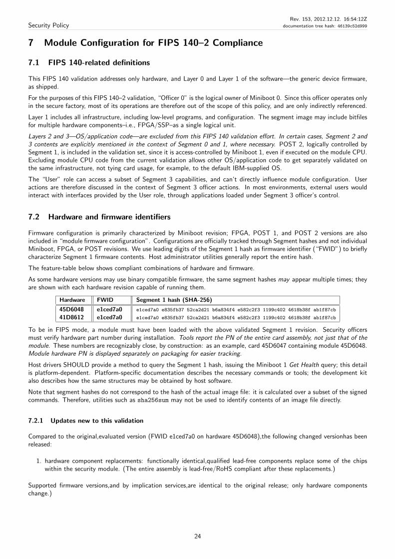
7.2 Hardware and firmware identifiers . . . . . . . . . . . . . . . . . . . . . . . . . . . . . . . . . . . . . . . . 24
7.2.1 Updates new to this validation . . . . . . . . . . . . . . . . . . . . . . . . . . . . . . . . . . . . . 24
7.3 Layers 2 and 3 . . . . . . . . . . . . . . . . . . . . . . . . . . . . . . . . . . . . . . . . . . . . . . . . . . 25
7.4 Usage of non-approved algorithms or Modes of operation . . . . . . . . . . . . . . . . . . . . . . . . . . . 25
7.5 Determining Mode of Operation . . . . . . . . . . . . . . . . . . . . . . . . . . . . . . . . . . . . . . . . 25
8 Module Officer/User Guidance 27
8.1 Physical Security Inspection/Testing Recommendations . . . . . . . . . . . . . . . . . . . . . . . . . . . . 27
8.2 Module initialization and delivery . . . . . . . . . . . . . . . . . . . . . . . . . . . . . . . . . . . . . . . . 28
8.3 Miscellaneous . . . . . . . . . . . . . . . . . . . . . . . . . . . . . . . . . . . . . . . . . . . . . . . . . . 28
9 Predecessors: the 4758 and 4764 families 29
10 Glossary 30
2
Security PolicyRev. 153, 2012.12.12. 16:54:12Z
documentation tree hash: 46139c52d999
1 Scope of Document
This document describes services that the security module of IBM 4765 Cryptographic Coprocessors (“the module”, alsoknown as “the module of the 4765”) with Miniboot software resident in ROM and code flash, provides to a population ofsecurity officers, users, and the security policy governing access to those services. This policy applies to multiple membersof the 4765 product family. We describe multiple firmware revisions, highlighting differences where appropriate.
Firmware identifiers refer to unambiguously identifiable leading characters of Segment 1 (firmware) hash, a unique valuedescribing firmware configuration. The actual value, a cryptographic hash of the segment image, is returned by configurationqueries. This policy applies to the following firmware identifiers: e1ced7a0, e1ced7a0, when loaded to cards with asupported hardware part number. Please see Section 7 (p. 24) for validated combinations of hardware and firmware.
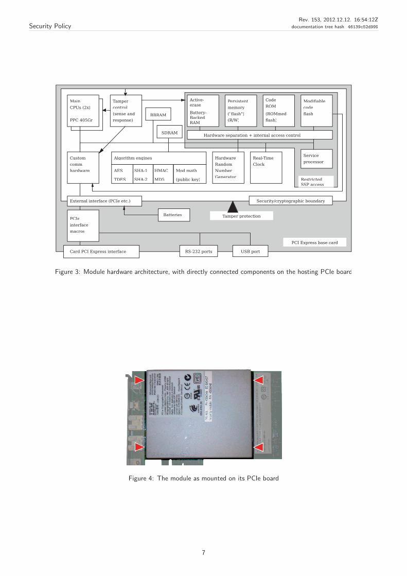
Describing the module, this document buils on the foundations of previously validated IBM 4764 and 4758 families–seepage 29. We use “module” to refer to the security unit, which features the security boundary as its external surface (Fig. 4).If we mention properties of the entire card assembly, such as the PCIe board the module is mounted on, the distinction isunambiguously noted. Differences between members of the 4765 family are also described in this policy for reference.
Background The 4765 is a programmable secure coprocessor. Its module consists of:
• base hardware, a general-purpose environment with security-relevant additions, such as cryptographic acceleratorhardware and tamper-protection circuitry;
• hardware-based partitioning functionality, creating multiple, hierarchical layers (“Segments”), primarily separatinginfrastructure (Segments 0/1) from OS/applications (Segments 2/3).
• embedded firmware not observable to the outside; executed by the internal security processor, the SSP. Embeddedfirmware also contains power-on selftests (POST), segmented along with the rest of the code, Segments 0 to 2.
• Miniboot software, which controls security and configuration of the device, and provides externally visible services
• higher system software and application layers.
OS/applications are executed on “the” processor (“module CPU”), physically separated from the SSP.
Note that this policy covers services of trusted, lower layers of internal firmware (Layers 0 and 1, and a stub of Layer 2).Higher layers, OS and applications (2 and 3) are not included in the current validation. Our security foundations do notrequire a cooperative or trustworthy OS/application for consistent and secure Miniboot operation.
The cryptographic boundary is the enclosure of the self-contained module of 4765 cards (hardware part number 41D8612).The module is labeled unambiguously with model and part numbers of the host PCIe card, and that of the module itself(Fig. 4). The correspondence between end-user product, module, and security policy is self-explanatory.
We allow Miniboot to distrust and influence OS/application behavior. Internal, non-infrastructure code is executed on adedicated processor; access control of Miniboot secrets is enforced by infrastructure and is not influenced by OS/applicationcode. Inter-processor interaction is limited to the following:
1. The SSP may reset the module CPU at any time. Most Miniboot commands do this, queries generally do not.
2. The SSP may pass data to the module CPU, shared through regions that are readable by the module CPU.
Data sharing is generally unidirectional, and is controlled entirely by the SSP. We describe exceptions where applicable.
3. The SSP receives and acts on module CPU status output. The only security-relevant instance is the SSP waiting forsuccessful module CPU startup testing, as performed by POST 2. In this case, the code executed by the module CPUlogically belongs to firmware, i.e., it is part of privileged code, out of OS/application control.
The combination of hardware and Miniboot provide security foundations of module; what a particular instance ends updoing is controlled by higher software layers. However, what goes into these layers, and how their secrets are preservedor destroyed, is controlled by Miniboot. Miniboot also provides “outbound authentication” (OA), module-internal signingservices to securely authenticate module entities. Applications can build on OA to establish trust in other entities, provingthat their instance runs within a specific module, including unique identification of the particular module.
Validation of this basic platform establishes that, no matter what is loaded into Layer 2 and Layer 3, our platform is secure:
• Miniboot always correctly configures and identifies what’s in these layers
3
Security PolicyRev. 153, 2012.12.12. 16:54:12Z
documentation tree hash: 46139c52d999
• Only Miniboot is allowed to update internal executable content, both privileged and OS/application code. This makesour system immune to infrastructure-level compromise by hostile OS/application code.
• If an entity uses outbound authentication, which Miniboot validates to belong to Miniboot of an an untampered cardin a specified application configuration, then either:
– that entity is that application configuration, on that untampered card,
– or that application configuration on that card gave away its key.
For OS/application code in Segment 2/3, internal infrastructure is not modifiable—its functionality is considered to befixed. Therefore, for a compound security validation combining Segment 0/1 and 2/3 segments, Miniboot will be applicableas described in this document; for OS/application code, security requirements of non-modifiable environments apply.
Follow-on Hardware Current hardware offers improvements over previous hardware generations:
• Separation of firmware security management (dedicated “service processor”) and OS/application execution. OS andapplications execute on a processor without write access to code flash.
Since functionality is now physically separated between trusted and untrusted code, the security infrastructure issimpler than in previous card generations.
• The module CPU is a redundant embedded PowerPC (405Gr). Replication, while itself software-transparent, allowssimplification of certain self-tests, as module CPU failures are detected through redundant computation.
• CPU-type device are integrated into an FPGA, reducing physical size of a potential tamper target.
• Integrated tamper detection, response, and actively erased BBRAM regions replace previous discrete tamper circuitry.Core secrets reside within the “high-speed erase BBRAM” (HSEB).
• Significantly increased memory sizes, both persistent and transient memory.
In addition to the HSEB, traditional BBRAM sizes also increased. Slower flash chips have been replaced by BBRAM,without impacting applications using persistent memory. Traditional BBRAM is crowbarred and discharged upontamper events, as was in previous 47xx families.
• Hardware support for additional algorithms, such as SHA-256 and HMAC
• Hardware supports larger modular math calculations than previous card families
• Directly-connected USB port, with limited device/type support
Other, less significant hardware improvements are described as appropriate.
Differences between 4765 versions are specifically highlighted, where applicable, if relevant.
Note that the 4765 designation, in IBM terminology, is a machine type/model number of an entire card assembly,or simply model in casual use. Modules may be assigned different feature codes in configurations, especiallyif embedded in another subsystem, such as I/O boards in mainframes. Feature codes containing the samecards may also be different in different server platforms. Since modules only trust entities within their secureenclosures, and their security officers, the actual host platform and further packaging does not affect our securityfoundations.
Independent of the actual final feature code, the card machine type 4765 does not change.
Since the module does not (need to) trust its PCIe host, therefore it is prudent and reasonable to use thecard-specific designation to identify modules. In certain cases, references may still be made to the behavioror PCIe properties of the host system, irrespective of the actual platform. Such distinction is necessary, forexample, where discussing connectivity tests, which require host interaction.
2 Secure coprocessor overview
A multi-chip embedded product, the 4765 is intended to be a high-end secure coprocessor: a device with a general-purposecomputation environment and high-performance crypto support, which executes software and retains secrets, despite fore-seeable physical or logical attacks. Customers can use this secure platform as a foundation for their own secure applications,such as high-assurance digital signature generation or financial transaction processing.
4
Security PolicyRev. 153, 2012.12.12. 16:54:12Z
documentation tree hash: 46139c52d999
Miniboot Base Miniboot code helps achieve security goals by permitting software:
• to load and execute safely, in a controlled manner,
• allow entities to authenticate interaction with a specific untampered device in a specific software configuration,
• maintain a consistent host-visible module state, or force the module to stop if in an unexpected state.
• update code, if authorized, including updates to portions of Miniboot itself.
Authenticating the configuration Verifying that one is interacting with an untampered device operating the correctsoftware is necessary for both classes of applications:
• Standalone devices, such as cryptographic accelerators. If a user cannot verify that their crypto provider is bothuntampered, and operating the intended software, then their entire cryptographic operation may be compromised.
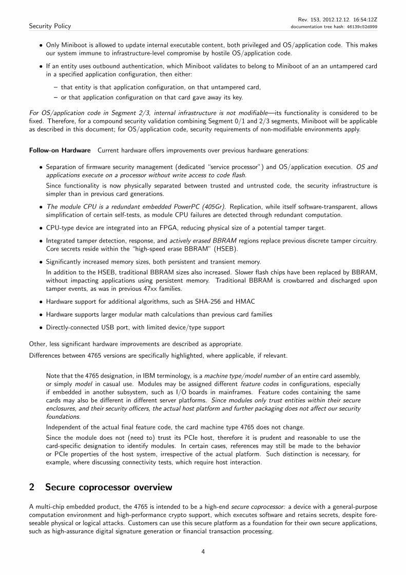
• Distributed applications. Many scenarios require one party to be able to trust computation at a remote site, whichis under the physical control of a party who may benefit from tampering with this computation. See Fig. 1.
The module provides outbound authentication: internal, non-exportable private keys can sign things output from the module.OA!features are integral to Segments 1 and 2; Segment 3 entities—applications—access OA services through an exposedSegment 2 interface. While offering similar services, OA signatures distinguish Miniboot and Segment 2 certificates, thereforeother parties may unambiguously identify Miniboot and OS/application originated authentication.
Maximum flexibility, minimal trust We obey previously described security rules while accommodating constraints:
• no trusted couriers or on-site security officers are needed to operate modules
• IBM maintains no database of device secrets
• IBM does need to see application software
• rewritable OS or applications can fail, or behave with malice, without compromising the integrity of lower layers
• IBM or other infrastructure developers have no “backdoor access” to customer’s on-card secrets. Obviously, one cannot provide guarantees about third-party code within the internal OS or applications, such as custom extensions.Assurance of such code is outside the scope of this document.
Secure Platform Our goal is to produce secure infrastructure on which developers—including IBM—can build secureapplications. Our module, for validation, consists of all hardware within the secure boundary, along with the foundationalMiniboot software.
By obtaining FIPS 140–2 validation for our hardware and bootstrap/configuration control software (Layer 0 and Layer 1,plus POST 2, see Fig. 5), we make it easy for developers to build and deploy secure applications. Obtaining FIPS 140–2validation for such applications would require additional documentation and a separate validation for software built for ourmodule’s environment, having it evaluated for secure operation specifically within our module. Software evaluated in thisenvironment would inherit the physical protection afforded by our Level 4 enclosure.
Validating this platform at Level 4 customers the flexibility to design to any FIPS 140–2 Security Level of any code built ontop of the 4765 infrastructure.
More information For details and history of the security architecture of the IBM 47xx families of devices, see:
• S. W. Smith, S. H. Weingart. “Building a High-Performance,Programmable Secure Coprocessor.” Computer Networks,Special Issue on Network Security. 31: 831-860. April 1999.
5
Security PolicyRev. 153, 2012.12.12. 16:54:12Z
documentation tree hash: 46139c52d999
localstorage
CPUCPUlocalstorage
application application
Secure coprocessor
IBM 47xx
Secure coprocessor
IBM 47xxIBM 47xx
Factory CA
(untrusted entities)
Figure 1: We enable users, who have never met, to use our hardware, download software from their chosen security officers,then interact securely—each able to verify that they are talking to the proper counterparty
device2 certificate chaindevice1 certificate chain IBM Factory CA
Segment 1 certificates
Segment 2 OA (device 1) Segment 2 OA (device 2)
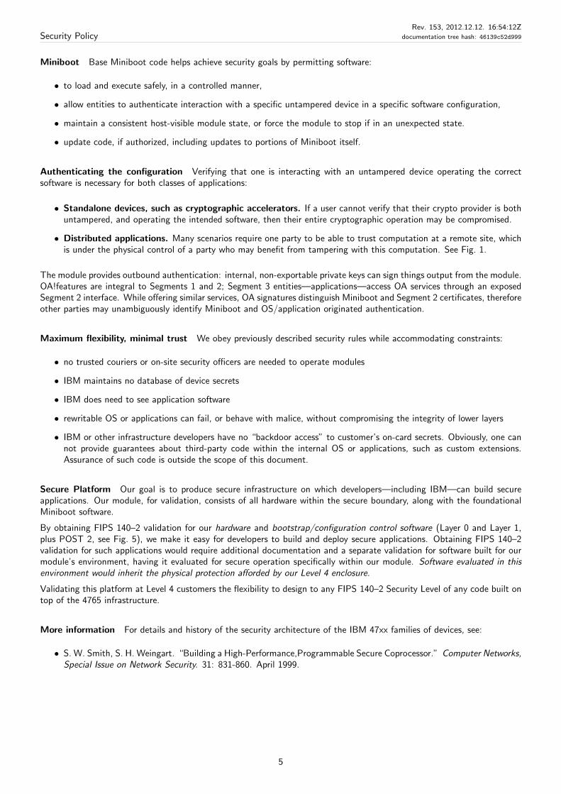
Figure 2: Cards’ mutual authentication through the Factory CA, certificate chains of Miniboot1 keys, and Segment 2 OA
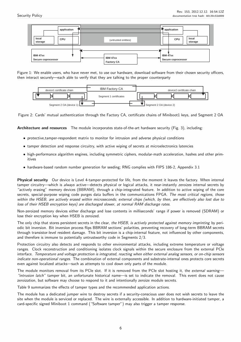
Architecture and resources The module incorporates state-of-the-art hardware security (Fig. 3), including:
• protective,tamper-respondent matrix to monitor for intrusion and adverse physical conditions
• tamper detection and response circuitry, with active wiping of secrets at microelectronics latencies
• high-performance algorithm engines, including symmetric ciphers, modular-math acceleration, hashes and other prim-itives
• hardware-based random number generation for seeding; RNG complies with FIPS 186-2, Appendix 3.1
Physical security Our device is Level 4-tamper-protected for life, from the moment it leaves the factory. When internaltamper circuitry—which is always active—detects physical or logical attacks, it near-instantly zeroizes internal secrets by“actively erasing” memory devices (BBRAM), through a chip-integrated feature. In addition to active wiping of the coresecrets, special-purpose wiping code purges data buffers in the communications FPGA. The most critical regions, thosewithin the HSEB, are actively erased within microseconds; external chips (which, by then, are effectively also lost due toloss of their HSEB encryption keys) are discharged slower, at normal RAM discharge rates.
Non-zeroized memory devices either discharge and lose contents in milliseconds’ range if power is removed (SDRAM) orlose their encryption key when HSEB is zeroized.
The only chip that stores persistent secrets in the clear, the HSEB, is actively protected against memory imprinting by peri-odic bit inversion. Bit inversion process flips BBRAM sections’ polarities, preventing recovery of long-term BBRAM secretsthrough transistor-level resident damage. This bit inversion is a chip-internal feature, not influenced by other components,and therefore is immune to potentially untrustworthy code in Segments 2/3.
Protection circuitry also detects and responds to other environmental attacks, including extreme temperature or voltageranges. Clock reconstruction and conditioning isolates clock signals within the secure enclosure from the external PCIeinterface. Temperature and voltage protection is integrated, reacting when either external analog sensors, or on-chip sensorsindicate non-operational ranges. The combination of external components and substrate-internal ones protects core secretseven against localized attacks—such as attempts to cool down only parts of the module.
The module monitors removal from its PCIe slot. If it is removed from the PCIe slot hosting it, the external warning—“intrusion latch” tamper bit, an unfortunate historical name—is set to indicate the removal. This event does not causezeroization, but software may choose to respond to it and intentionally zeroize module secrets.
Table 9 summarizes the effects of tamper types and the recommended application actions.
The module has a dedicated jumper wire to destroy secrets if a security-conscious user does not wish secrets to leave thesite when the module is serviced or replaced. The wire is externally accessible. In addition to hardware-initiated tamper, acard-specific signed Miniboot 1 command (“Software tamper”) may also trigger a tamper response.
6
Security PolicyRev. 153, 2012.12.12. 16:54:12Z
documentation tree hash: 46139c52d999
HardwareRandomNumberGenerator
ClockReal-Time
(R/W)
Persistent
("flash")memory
Hardware separation + internal access control
External interface (PCIe etc.)
(ROMmedflash)
ROMCode
PCIe
macrosinterface
Customcomm.hardware
flashcodeModifiable
TDES
AES
Algorithm engines
(public key)
Mod math
SHA-2
SHA-1 HMACSHA-1 HMACSHA-1 HMAC
MD5
PCI Express base card
BBRAM
SDRAM
Main
PPC 405Gr
CPUs (2x)
response)
Tampercontrol(sense and
RAMBackedBattery-
Active-erase
processorService
RestrictedSSP access
Tamper protection
Security/cryptographic boundary
USB portRS-232 portsCard PCI Express interface
Batteries
Figure 3: Module hardware architecture, with directly connected components on the hosting PCIe board
Figure 4: The module as mounted on its PCIe board
7
Security PolicyRev. 153, 2012.12.12. 16:54:12Z
documentation tree hash: 46139c52d999
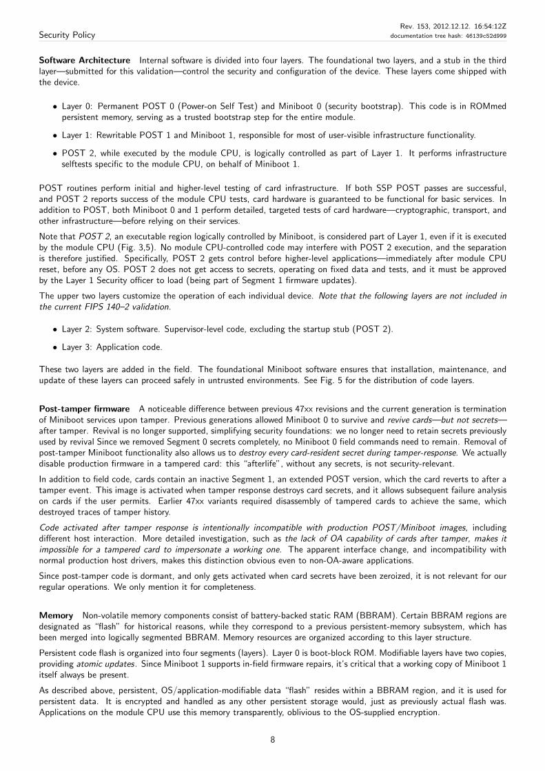
Software Architecture Internal software is divided into four layers. The foundational two layers, and a stub in the thirdlayer—submitted for this validation—control the security and configuration of the device. These layers come shipped withthe device.
• Layer 0: Permanent POST 0 (Power-on Self Test) and Miniboot 0 (security bootstrap). This code is in ROMmedpersistent memory, serving as a trusted bootstrap step for the entire module.
• Layer 1: Rewritable POST 1 and Miniboot 1, responsible for most of user-visible infrastructure functionality.
• POST 2, while executed by the module CPU, is logically controlled as part of Layer 1. It performs infrastructureselftests specific to the module CPU, on behalf of Miniboot 1.
POST routines perform initial and higher-level testing of card infrastructure. If both SSP POST passes are successful,and POST 2 reports success of the module CPU tests, card hardware is guaranteed to be functional for basic services. Inaddition to POST, both Miniboot 0 and 1 perform detailed, targeted tests of card hardware—cryptographic, transport, andother infrastructure—before relying on their services.
Note that POST 2, an executable region logically controlled by Miniboot, is considered part of Layer 1, even if it is executedby the module CPU (Fig. 3,5). No module CPU-controlled code may interfere with POST 2 execution, and the separationis therefore justified. Specifically, POST 2 gets control before higher-level applications—immediately after module CPUreset, before any OS. POST 2 does not get access to secrets, operating on fixed data and tests, and it must be approvedby the Layer 1 Security officer to load (being part of Segment 1 firmware updates).
The upper two layers customize the operation of each individual device. Note that the following layers are not included inthe current FIPS 140–2 validation.
• Layer 2: System software. Supervisor-level code, excluding the startup stub (POST 2).
• Layer 3: Application code.
These two layers are added in the field. The foundational Miniboot software ensures that installation, maintenance, andupdate of these layers can proceed safely in untrusted environments. See Fig. 5 for the distribution of code layers.
Post-tamper firmware A noticeable difference between previous 47xx revisions and the current generation is terminationof Miniboot services upon tamper. Previous generations allowed Miniboot 0 to survive and revive cards—but not secrets—after tamper. Revival is no longer supported, simplifying security foundations: we no longer need to retain secrets previouslyused by revival Since we removed Segment 0 secrets completely, no Miniboot 0 field commands need to remain. Removal ofpost-tamper Miniboot functionality also allows us to destroy every card-resident secret during tamper-response. We actuallydisable production firmware in a tampered card: this “afterlife”, without any secrets, is not security-relevant.
In addition to field code, cards contain an inactive Segment 1, an extended POST version, which the card reverts to after atamper event. This image is activated when tamper response destroys card secrets, and it allows subsequent failure analysison cards if the user permits. Earlier 47xx variants required disassembly of tampered cards to achieve the same, whichdestroyed traces of tamper history.
Code activated after tamper response is intentionally incompatible with production POST/Miniboot images, includingdifferent host interaction. More detailed investigation, such as the lack of OA capability of cards after tamper, makes itimpossible for a tampered card to impersonate a working one. The apparent interface change, and incompatibility withnormal production host drivers, makes this distinction obvious even to non-OA-aware applications.
Since post-tamper code is dormant, and only gets activated when card secrets have been zeroized, it is not relevant for ourregular operations. We only mention it for completeness.
Memory Non-volatile memory components consist of battery-backed static RAM (BBRAM). Certain BBRAM regions aredesignated as “flash” for historical reasons, while they correspond to a previous persistent-memory subsystem, which hasbeen merged into logically segmented BBRAM. Memory resources are organized according to this layer structure.
Persistent code flash is organized into four segments (layers). Layer 0 is boot-block ROM. Modifiable layers have two copies,providing atomic updates. Since Miniboot 1 supports in-field firmware repairs, it’s critical that a working copy of Miniboot 1itself always be present.
As described above, persistent, OS/application-modifiable data “flash” resides within a BBRAM region, and it is used forpersistent data. It is encrypted and handled as any other persistent storage would, just as previously actual flash was.Applications on the module CPU use this memory transparently, oblivious to the OS-supplied encryption.
8
Security PolicyRev. 153, 2012.12.12. 16:54:12Z
documentation tree hash: 46139c52d999
driver
Layer 3: Application
Layer 2: System Software/OS (Linux) POST2
Host
Application
network?Device
Seg1 flash
Layer 1: IBM POST1, Miniboot 1
Layer 0: IBM POST0, Miniboot 0Seg0 ROM
Scope of Segment 0-1 validation
Figure 5: Module software architecture.
Hardware Locks Since Miniboot is restricted to a certain part of the hosting FPGA, and its resources are unavailable tothe module CPU, our hardware segmentation is a considerably simplified version of previous “hardware lock management”(HLM). In our simplified model, Miniboot may write all code—in flash—and may push information to the module CPU,while the latter is restricted to read-only access to designated shared regions (Fig. 3, 9). We continue to refer to theremaining functionality as “HLM”, even if has been merged into base infrastructure.
As access to memory regions is unconditionally restricted by hardware, much of previous complexity has been removed. Thecurrent generation, in fact, does not require the granular racketing present in the predecessor 47xx variants: we effectivelytreat any module CPU code as untrusted from a Miniboot perspective (POST 2 is trusted to return a pass/fail result).
• The “HLM” also contains, under hardware enforcement, the “factory sticky bit” (“initialized” indicator). Once thishardware-protected bit is activated, it will never revert to the non-initialized state.
The initialization bit prevents the module from reinitialization, once it has completed the process. It is set upondevice—Segment 1—keypair generation, and allows us to reinitialize cards if they fail intermittently during manufac-turing. Activating this bit disables Miniboot services limited to factory use, for the rest of module lifetime.
• The “sticky bit” implementation resides within dedicated hardware. This hardware-enforcement—with Minibootassistance—guarantees that the card follows its expected lifecycle. Unexpected state of this state model triggers aninvoluntary card tamper, assuming some fundamental hardware failure.
Hardware separation of the SSP and module CPU is a critical part of ensuring that the Miniboot security software worksdespite potentially arbitrary software in Layers 2 and 3.
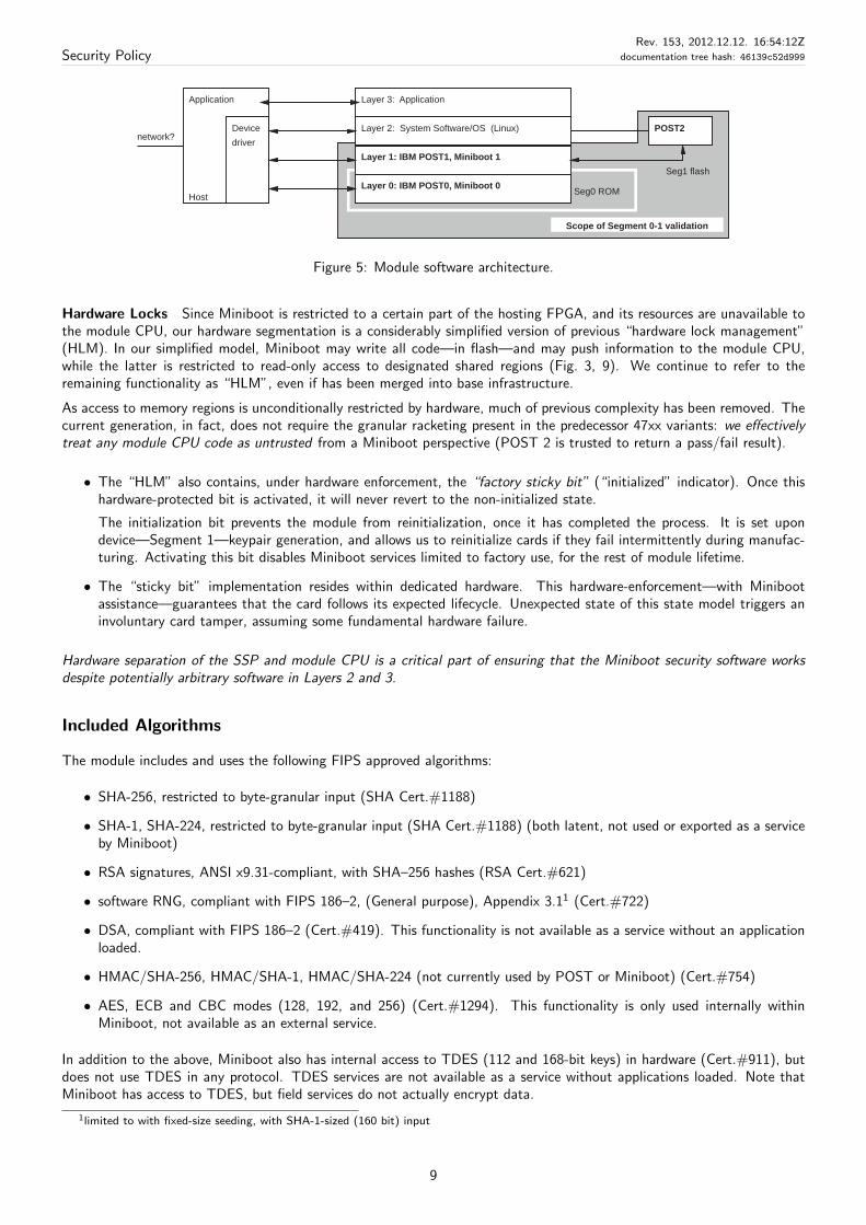
Included Algorithms
The module includes and uses the following FIPS approved algorithms:
• SHA-256, restricted to byte-granular input (SHA Cert.#1188)
• SHA-1, SHA-224, restricted to byte-granular input (SHA Cert.#1188) (both latent, not used or exported as a serviceby Miniboot)
• RSA signatures, ANSI x9.31-compliant, with SHA–256 hashes (RSA Cert.#621)
• software RNG, compliant with FIPS 186–2, (General purpose), Appendix 3.11 (Cert.#722)
• DSA, compliant with FIPS 186–2 (Cert.#419). This functionality is not available as a service without an applicationloaded.
• HMAC/SHA-256, HMAC/SHA-1, HMAC/SHA-224 (not currently used by POST or Miniboot) (Cert.#754)
• AES, ECB and CBC modes (128, 192, and 256) (Cert.#1294). This functionality is only used internally withinMiniboot, not available as an external service.
In addition to the above, Miniboot also has internal access to TDES (112 and 168-bit keys) in hardware (Cert.#911), butdoes not use TDES in any protocol. TDES services are not available as a service without applications loaded. Note thatMiniboot has access to TDES, but field services do not actually encrypt data.
1limited to with fixed-size seeding, with SHA-1-sized (160 bit) input
9
Security PolicyRev. 153, 2012.12.12. 16:54:12Z
documentation tree hash: 46139c52d999
Security requirements section Level
Cryptographic Module Specification 4Module Ports and Interfaces 4Roles, Services, and Authentication 4
Finite State Model 4
Physical Security 4Software Security 4Operational Environment N/A
Cryptographic Key Management 4EMI/EMC 4Self-Tests 4
Design Assurance 4
Mitigation of Other Attacks N/A
Table 1: Module Security Level specification.
SHA-256 is used in as an integrity check of certain internal structures. Firmware integrity is protected by this hash, protectingagainst random corruption2. While none of this SHA-256 calculation is externally observable, use of the algorithm for EDCgeneration is mentioned here for completeness.
The module includes FIPS allowed internal seed generation, feeding an Approved RNG.
The module also includes the following non-FIPS-approved algorithms:
• MD5, on byte-granular input (latent, not used by Miniboot)
• DES (latent, not used by Miniboot)
• DES MAC (Miniboot uses DES MAC as integrity check for certain internal structures, not available as a service)
Higher-level software layers may provide and other algorithms, out of scope of this document.
3 Cryptographic module Security Level
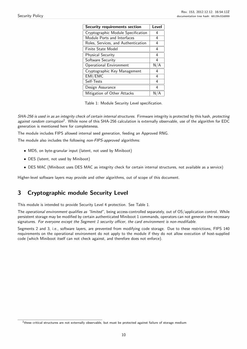
This module is intended to provide Security Level 4 protection. See Table 1.
The operational environment qualifies as “limited”, being access-controlled separately, out of OS/application control. Whilepersistent storage may be modified by certain authenticated Miniboot 1 commands, operators can not generate the necessarysignatures. For everyone except the Segment 1 security officer, the card environment is non-modifiable.
Segments 2 and 3, i.e., software layers, are prevented from modifying code storage. Due to these restrictions, FIPS 140requirements on the operational environment do not apply to the module if they do not allow execution of host-suppliedcode (which Miniboot itself can not check against, and therefore does not enforce).
2these critical structures are not externally observable, but must be protected against failure of storage medium
10
Security PolicyRev. 153, 2012.12.12. 16:54:12Z
documentation tree hash: 46139c52d999
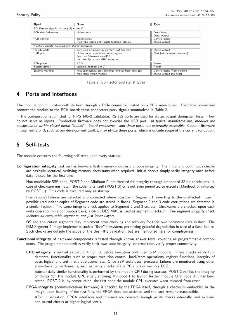
Signal Notes Type
PCI Express signals: 4-lane (x4) external
PCIe data/addresses bidirectional Data, input;Data, output
PCIe control bidirectional;PCIe v1.1 compliant “single function” device
Control inputStatus output
Auxiliary signals, tunneled over shared flexcables
RS-232 ports only used as output by current IBM firmware Status outputUSB port bidirectional; may tunnel other signals
(such as Ethernet-over-USB)not used by current IBM firmware
N/A (with current firmware)
PCIe power 3.3 V PowerBattery power variable, nominal 3.0 V Power
External warning host connectivity test, latching removal from host busmonitored within module
Control input (from sensor)Status output (to host)
Table 2: Connector and signal types
4 Ports and interfaces
The module communicates with its host through a PCIe connector hosted on a PCIe main board. Flexcable connectorsconnect the module to the PCIe board; these connectors carry signals summarized in Table 2.
In the configuration submitted for FIPS 140–2 validation, RS-232 ports are used for status output during self-tests. Theydo not serve as inputs. Production firmware does not exercise the USB port. In typical mainframe use, modules areencapsulated within closed metal “books”—board enclosures—and these ports not externally accessible. Custom firmwarein Segment 2 or 3, such as our development toolkit, may utilize these ports, which is outside scope of the current validation.
5 Self-tests
The module executes the following self-tests upon every startup:
Configuration integrity test verifies firmware flash memory modules and code integrity. The initial and continuous checksare basically identical, verifying memory checksums when required. Initial checks simply verify integrity once beforedata is used for the first time.
Non-modifiable SSP code, POST 0 and Miniboot 0, are checked for integrity through embedded 32-bit checksums. Incase of checksum mismatch, the code halts itself (POST 0) or is not even permitted to execute (Miniboot 0, inhibitedby POST 0). This code is executed only at startup.
Flash (code) failures are detected and corrected where possible in Segment 1, reverting to the unaffected image ifpossible (redundant copies of Segment code are stored in flash). Segment 2 and 3 code corruptions are detected ina similar fashion. The same integrity check applies to Segment 2 and 3 secrets. Checksums are checked upon eachwrite operation on a continuous basis; a 64-bit DES MAC is used as segment checksum. The segment integrity checkincludes all executable segments, not just lower Layers.
OS and application segments may implement error checking and recovery for their own persistent data in flash. TheIBM Segment 2 image implements such a “flash” filesystem, permitting graceful degradation in case of a flash failure.Such checks are outside the scope of the this FIPS validation, but are mentioned here for completeness.
Functional integrity of hardware components is tested through known answer tests, covering all programmable compo-nents. The programmable devices verify their own code integrity; external tests verify proper connectivity.
CPU integrity is verified as part of POST 0, before execution continues to Miniboot 0. These checks verify fun-damental functionality, such as proper execution control, load/store operations, register functions, integrity ofbasic logical and arithmetic operations, etc. Once SSP tests pass, processor failures are monitored using othererror-checking mechanisms, such as parity checks of the PCIe bus or memory ECC.
Substantially similar functionality is performed by the module CPU during startup. POST 2 verifies the integrityof things “on the module CPU side”, allowing Miniboot 1 to launch further module CPU code if it has beentested. POST 2 is, by construction, the first code the module CPU executes when released from reset.
FPGA integrity (communications firmware) is checked by the FPGA itself, through a checksum embedded in theimage, upon loading. If the test fails, the FPGA does not activate, and the card remains inaccessible.
After initialization, FPGA interfaces and internals are covered through parity checks internally, and externalend-to-end checks at higher logical levels.
11
Security PolicyRev. 153, 2012.12.12. 16:54:12Z
documentation tree hash: 46139c52d999
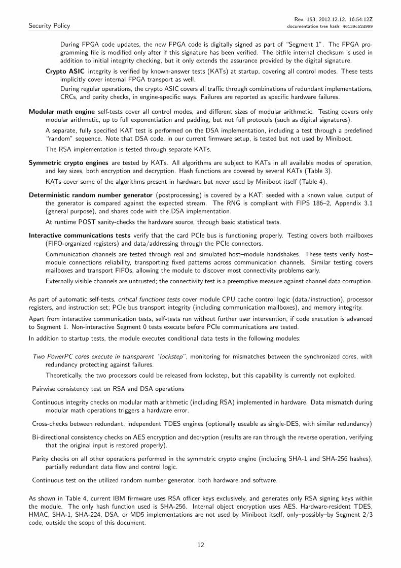
During FPGA code updates, the new FPGA code is digitally signed as part of “Segment 1”. The FPGA pro-gramming file is modified only after if this signature has been verified. The bitfile internal checksum is used inaddition to initial integrity checking, but it only extends the assurance provided by the digital signature.
Crypto ASIC integrity is verified by known-answer tests (KATs) at startup, covering all control modes. These testsimplicitly cover internal FPGA transport as well.
During regular operations, the crypto ASIC covers all traffic through combinations of redundant implementations,CRCs, and parity checks, in engine-specific ways. Failures are reported as specific hardware failures.
Modular math engine self-tests cover all control modes, and different sizes of modular arithmetic. Testing covers onlymodular arithmetic, up to full exponentiation and padding, but not full protocols (such as digital signatures).
A separate, fully specified KAT test is performed on the DSA implementation, including a test through a predefined“random” sequence. Note that DSA code, in our current firmware setup, is tested but not used by Miniboot.
The RSA implementation is tested through separate KATs.
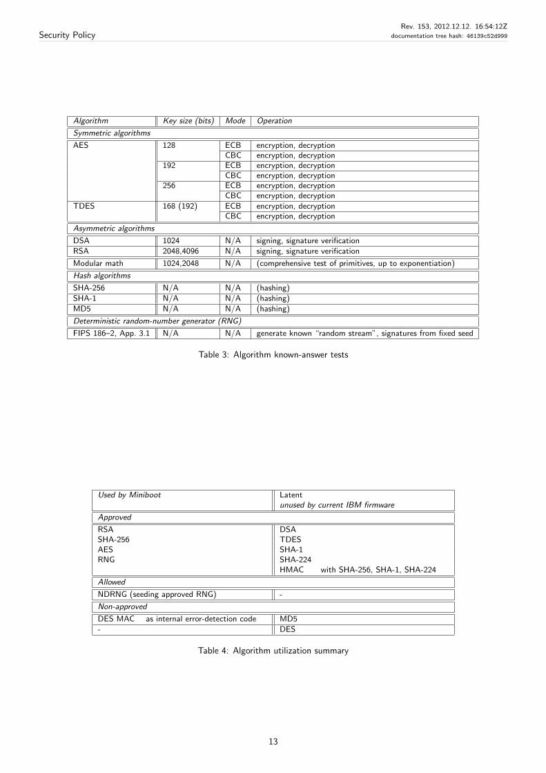
Symmetric crypto engines are tested by KATs. All algorithms are subject to KATs in all available modes of operation,and key sizes, both encryption and decryption. Hash functions are covered by several KATs (Table 3).
KATs cover some of the algorithms present in hardware but never used by Miniboot itself (Table 4).
Deterministic random number generator (postprocessing) is covered by a KAT: seeded with a known value, output ofthe generator is compared against the expected stream. The RNG is compliant with FIPS 186–2, Appendix 3.1(general purpose), and shares code with the DSA implementation.
At runtime POST sanity-checks the hardware source, through basic statistical tests.
Interactive communications tests verify that the card PCIe bus is functioning properly. Testing covers both mailboxes(FIFO-organized registers) and data/addressing through the PCIe connectors.
Communication channels are tested through real and simulated host–module handshakes. These tests verify host–module connections reliability, transporting fixed patterns across communication channels. Similar testing coversmailboxes and transport FIFOs, allowing the module to discover most connectivity problems early.
Externally visible channels are untrusted; the connectivity test is a preemptive measure against channel data corruption.
As part of automatic self-tests, critical functions tests cover module CPU cache control logic (data/instruction), processorregisters, and instruction set; PCIe bus transport integrity (including communication mailboxes), and memory integrity.
Apart from interactive communication tests, self-tests run without further user intervention, if code execution is advancedto Segment 1. Non-interactive Segment 0 tests execute before PCIe communications are tested.
In addition to startup tests, the module executes conditional data tests in the following modules:
Two PowerPC cores execute in transparent “lockstep”, monitoring for mismatches between the synchronized cores, withredundancy protecting against failures.
Theoretically, the two processors could be released from lockstep, but this capability is currently not exploited.
Pairwise consistency test on RSA and DSA operations
Continuous integrity checks on modular math arithmetic (including RSA) implemented in hardware. Data mismatch duringmodular math operations triggers a hardware error.
Cross-checks between redundant, independent TDES engines (optionally useable as single-DES, with similar redundancy)
Bi-directional consistency checks on AES encryption and decryption (results are ran through the reverse operation, verifyingthat the original input is restored properly).
Parity checks on all other operations performed in the symmetric crypto engine (including SHA-1 and SHA-256 hashes),partially redundant data flow and control logic.
Continuous test on the utilized random number generator, both hardware and software.
As shown in Table 4, current IBM firmware uses RSA officer keys exclusively, and generates only RSA signing keys withinthe module. The only hash function used is SHA-256. Internal object encryption uses AES. Hardware-resident TDES,HMAC, SHA-1, SHA-224, DSA, or MD5 implementations are not used by Miniboot itself, only–possibly–by Segment 2/3code, outside the scope of this document.
12
Security PolicyRev. 153, 2012.12.12. 16:54:12Z
documentation tree hash: 46139c52d999
Algorithm Key size (bits) Mode Operation
Symmetric algorithms
AES 128 ECB encryption, decryptionCBC encryption, decryption
192 ECB encryption, decryptionCBC encryption, decryption
256 ECB encryption, decryptionCBC encryption, decryption
TDES 168 (192) ECB encryption, decryptionCBC encryption, decryption
Asymmetric algorithms
DSA 1024 N/A signing, signature verification
RSA 2048,4096 N/A signing, signature verification
Modular math 1024,2048 N/A (comprehensive test of primitives, up to exponentiation)
Hash algorithms
SHA-256 N/A N/A (hashing)
SHA-1 N/A N/A (hashing)
MD5 N/A N/A (hashing)
Deterministic random-number generator (RNG)
FIPS 186–2, App. 3.1 N/A N/A generate known “random stream”, signatures from fixed seed
Table 3: Algorithm known-answer tests
Used by Miniboot Latentunused by current IBM firmware
Approved
RSA DSASHA-256 TDESAES SHA-1RNG SHA-224
HMAC with SHA-256, SHA-1, SHA-224
Allowed
NDRNG (seeding approved RNG) -
Non-approved
DES MAC as internal error-detection code MD5
- DES
Table 4: Algorithm utilization summary
13
Security PolicyRev. 153, 2012.12.12. 16:54:12Z
documentation tree hash: 46139c52d999
University 1 OEM 1 Bank 1 OEM 3IBM crypto API
officer
Bank 2Authority over
Layer 3
OEM 2IBM OS officer OEM 4
IBM Miniboot 1 officer
(IBM Miniboot 0 officer)
Layer 1
Layer 2
(Layer 0)
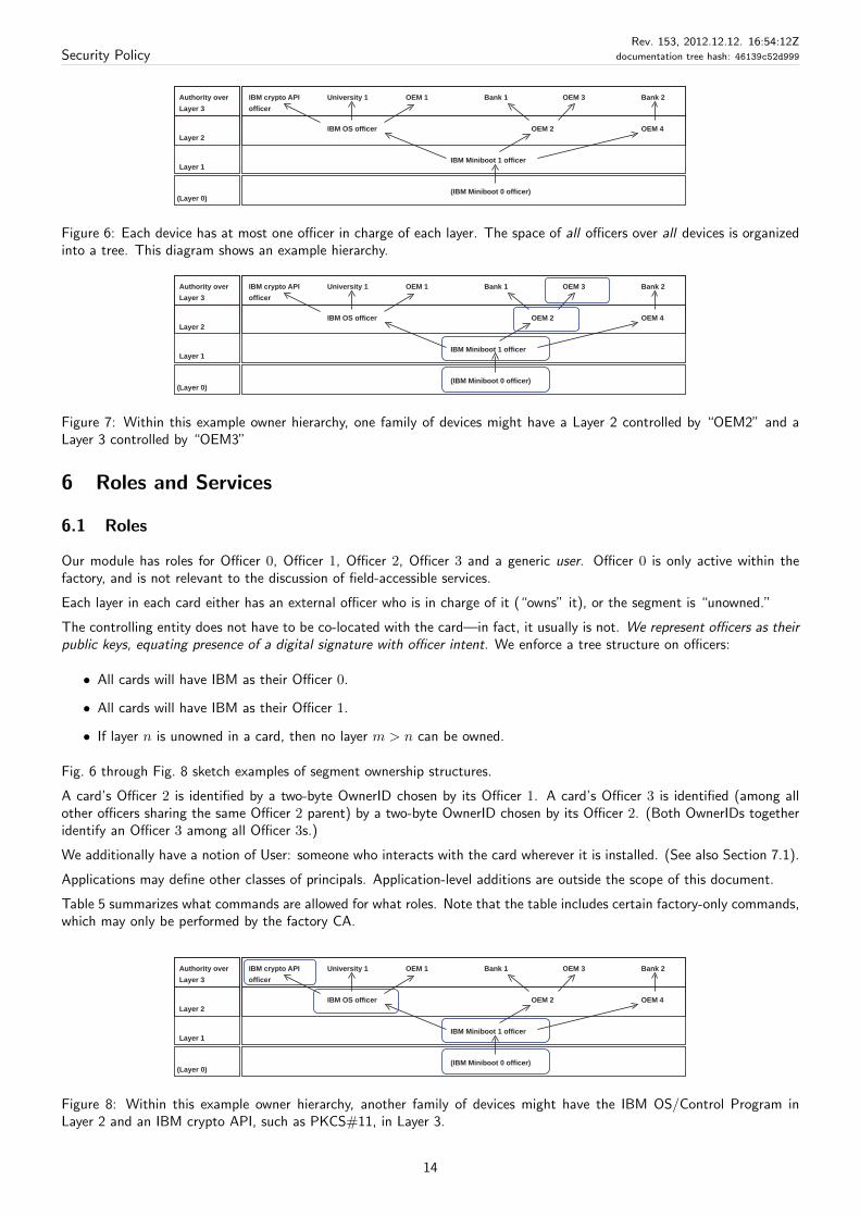
Figure 6: Each device has at most one officer in charge of each layer. The space of all officers over all devices is organizedinto a tree. This diagram shows an example hierarchy.
University 1 OEM 1 Bank 1 OEM 3IBM crypto API
officer
Bank 2Authority over
Layer 3
OEM 2IBM OS officer OEM 4
IBM Miniboot 1 officer
(IBM Miniboot 0 officer)
Layer 1
Layer 2
(Layer 0)
Figure 7: Within this example owner hierarchy, one family of devices might have a Layer 2 controlled by “OEM2” and aLayer 3 controlled by “OEM3”
6 Roles and Services
6.1 Roles
Our module has roles for Officer 0, Officer 1, Officer 2, Officer 3 and a generic user. Officer 0 is only active within thefactory, and is not relevant to the discussion of field-accessible services.
Each layer in each card either has an external officer who is in charge of it (“owns” it), or the segment is “unowned.”
The controlling entity does not have to be co-located with the card—in fact, it usually is not. We represent officers as theirpublic keys, equating presence of a digital signature with officer intent. We enforce a tree structure on officers:
• All cards will have IBM as their Officer 0.
• All cards will have IBM as their Officer 1.
• If layer n is unowned in a card, then no layer m > n can be owned.
Fig. 6 through Fig. 8 sketch examples of segment ownership structures.
A card’s Officer 2 is identified by a two-byte OwnerID chosen by its Officer 1. A card’s Officer 3 is identified (among allother officers sharing the same Officer 2 parent) by a two-byte OwnerID chosen by its Officer 2. (Both OwnerIDs togetheridentify an Officer 3 among all Officer 3s.)
We additionally have a notion of User: someone who interacts with the card wherever it is installed. (See also Section 7.1).
Applications may define other classes of principals. Application-level additions are outside the scope of this document.
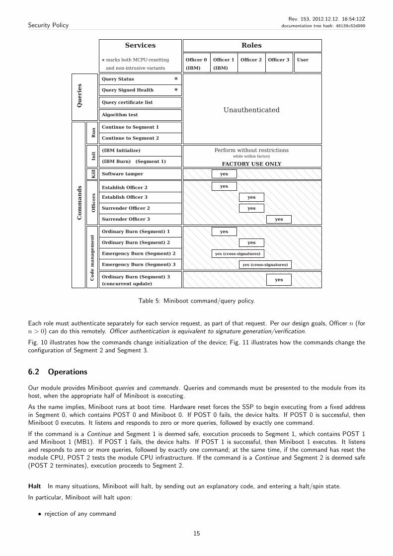
Table 5 summarizes what commands are allowed for what roles. Note that the table includes certain factory-only commands,which may only be performed by the factory CA.
University 1 OEM 1 Bank 1 OEM 3IBM crypto API
officer
Bank 2Authority over
Layer 3
OEM 2IBM OS officer OEM 4
IBM Miniboot 1 officer
(IBM Miniboot 0 officer)
Layer 1
Layer 2
(Layer 0)
Figure 8: Within this example owner hierarchy, another family of devices might have the IBM OS/Control Program inLayer 2 and an IBM crypto API, such as PKCS#11, in Layer 3.
14
Security PolicyRev. 153, 2012.12.12. 16:54:12Z
documentation tree hash: 46139c52d999
Ru
n
Continue to Segment 2
Continue to Segment 1
Algorithm test
Query certificate list
Query Signed Health *
Query Status *
Kil
lC
od
e m
an
ag
em
en
t
Emergency Burn (Segment) 3
Emergency Burn (Segment) 2
Ordinary Burn (Segment) 2
Ordinary Burn (Segment) 1
Ordinary Burn (Segment) 3
(concurrent update)
Establish Officer 3
Surrender Officer 2
Surrender Officer 3
Offi
cers
Establish Officer 2
Software tamper
Init
Com
man
ds
Qu
eri
es
Officer 0
(IBM) (IBM)
Officer 1 Officer 2 UserOfficer 3
yes
yes
yes
yes
yes
yes
yes
yes
FACTORY USE ONLY
while within factory
Perform without restrictions
Roles
marks both MCPU-resetting*
Services
and non-intrusive variants
(IBM Initialize)
(IBM Burn) (Segment 1)
yes (cross-signatures)
yes (cross-signatures)
Unauthenticated
Table 5: Miniboot command/query policy.
Each role must authenticate separately for each service request, as part of that request. Per our design goals, Officer n (forn > 0) can do this remotely. Officer authentication is equivalent to signature generation/verification.
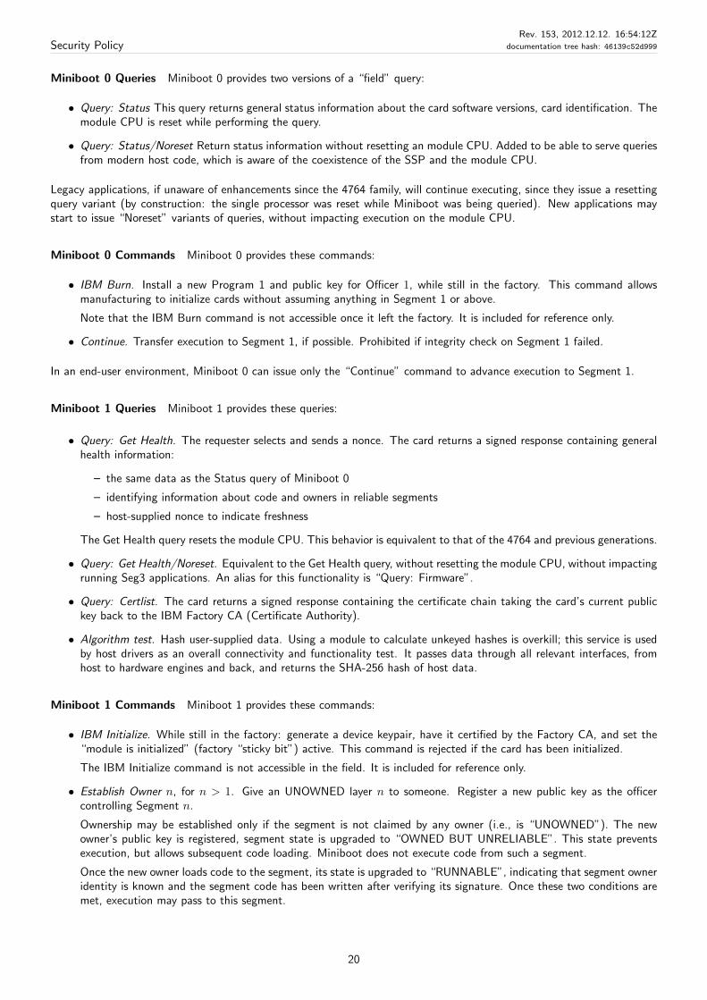
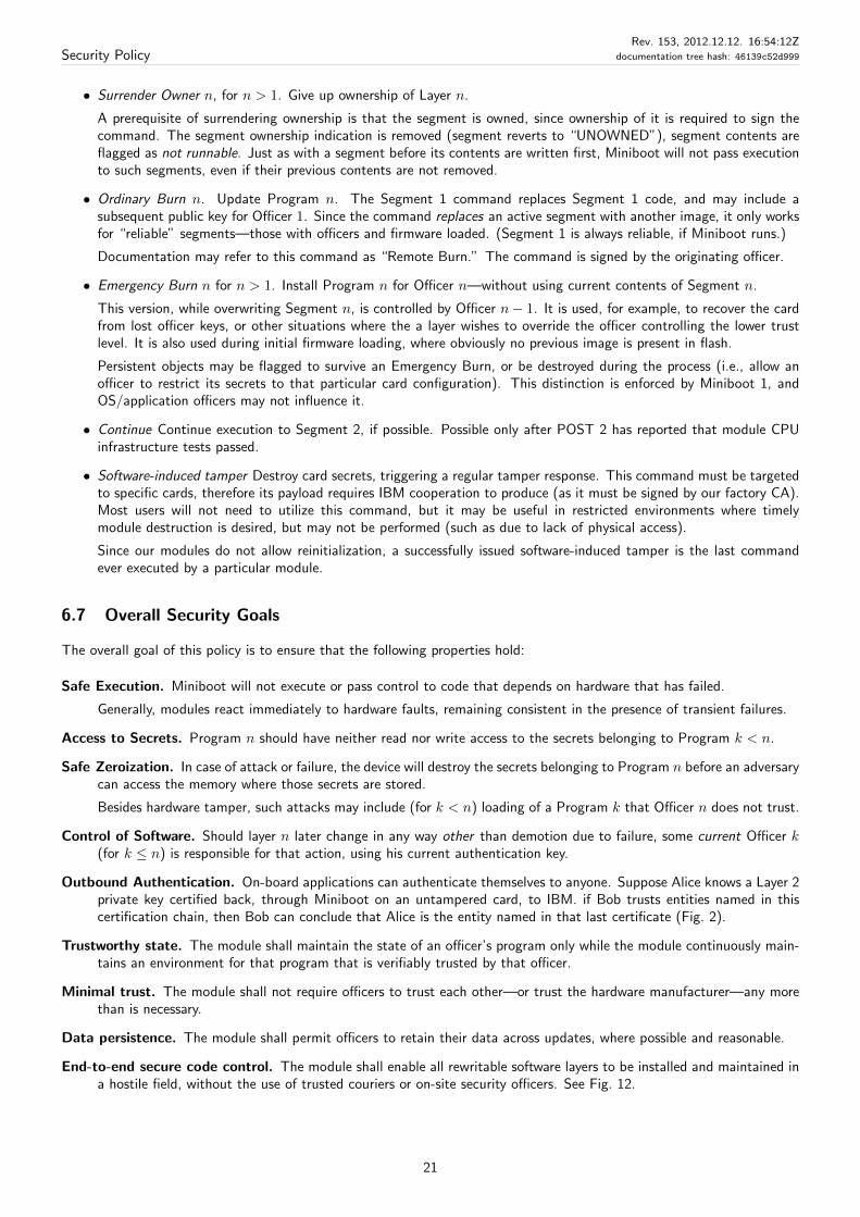
Fig. 10 illustrates how the commands change initialization of the device; Fig. 11 illustrates how the commands change theconfiguration of Segment 2 and Segment 3.
6.2 Operations
Our module provides Miniboot queries and commands. Queries and commands must be presented to the module from itshost, when the appropriate half of Miniboot is executing.
As the name implies, Miniboot runs at boot time. Hardware reset forces the SSP to begin executing from a fixed addressin Segment 0, which contains POST 0 and Miniboot 0. If POST 0 fails, the device halts. If POST 0 is successful, thenMiniboot 0 executes. It listens and responds to zero or more queries, followed by exactly one command.
If the command is a Continue and Segment 1 is deemed safe, execution proceeds to Segment 1, which contains POST 1and Miniboot 1 (MB1). If POST 1 fails, the device halts. If POST 1 is successful, then Miniboot 1 executes. It listensand responds to zero or more queries, followed by exactly one command; at the same time, if the command has reset themodule CPU, POST 2 tests the module CPU infrastructure. If the command is a Continue and Segment 2 is deemed safe(POST 2 terminates), execution proceeds to Segment 2.
Halt In many situations, Miniboot will halt, by sending out an explanatory code, and entering a halt/spin state.
In particular, Miniboot will halt upon:
• rejection of any command
15
Security PolicyRev. 153, 2012.12.12. 16:54:12Z
documentation tree hash: 46139c52d999
• successful completion of any command other than “Continue”
• detection of any error, either self-test or functional one
• detection of any other condition requiring alteration of configuration
Halting upon command completion is a design decision: always halting makes it easier to be sure that precondition checksand clean-up are applied in a known order. POST—in general, infrastructure—failures are treated similarly to Miniboot,halting the module after outputting a failure status.
Reset To resume operation, the user must cause another hardware reset. On a hardware level, the device can be reset by:
• power-cycling the device, such as controlling the power status of its PCIe slot
• triggering the designated control bit in the Bus Master Control/Status Register accessible from the PCIe host (itforces a module reset through the external PCIe bridge chip).
Internal firmware design acknowledges such interruptions; internal code must accommodate that the module may be resetat any particular point in time (such as performing atomic transactions, for example). Host drivers generally drive a statemachine in sync with the modules they drive, and will transparently issue resets whenever appropriate.
On a software level, IBM-supplied host-side device drivers will transparently reset the device (via the “Add-on Reset” signal)when appropriate:
• When the user “closes” the device after opening it for Miniboot
• When the user “opens” the device for Miniboot, but the device driver detects the device is halted.
• When the user opens the device for ordinary operation, but the host driver determines that the device is not al-ready open. In this case, the default IBM-supplied host drivers will transparently reset the device and also executeMiniboot 0 Continue and Miniboot 1 Continue, to try to advance to Program 2 code.
Receipts Upon successful command completion, Miniboot 1 returns a signed receipt, proving to a remote officer that thecommand actually took place, on an untampered card. Protocols include nonces to prevent replay.
6.3 Inbound Authentication
Miniboot authenticates each command request individually.
For 0 < N , Miniboot authenticates a command from Officer N by verifying that the public-key signature on the commandcame from the entity that is Officer N for that card, and was acting in that capacity when the signature was produced.This approach enables the officers to be located somewhere other than the devices they control.
In a module configured in FIPS mode, signatures are RSA-based (ANSI x9.31 padding, SHA-256 hash, 4096-bit RSA).Forging 4096-bit RSA signatures on segment contents is assumed to be infeasible.
After module initialization, Segment 0 commands are no longer available, therefore we do not effectively have Officer 0authentication. Segment 0 field operations are restricted to queries, not requiring authentication. Typically, host driversseparate userspace—non-OS code—from such access, which is outside the scope of this policy.
6.4 Outbound Authentication
At the last stage of manufacturing, Miniboot on a card generates its first keypair. IBM, through a Factory CA, certifies thepublic key to belong to that untampered card with that version of Miniboot. This certificate attests that the entity whichknows the private key matching that public key is that untampered card, with that Miniboot software. The certificationtakes place in the secure manufacturing vault.
Each time Miniboot 1 replaces itself, it generates a successor keypair and signs the new public key with its current privatekey. These transition certificates establish transitive trust in the sequence of Miniboot 1 keys.
If application configuration changes, Miniboot 1 also generates and certifies a keypair for Layer 2, replacing the previousone. This certification binds the keypair to a specific Layer 3 configuration. The binding between Segment 1 and 2 keypairs,coupled with the trust chain for Miniboot’s own keypair, permits parties to make accurate trust judgments about the entitywielding a private key certified this way (Fig. 2).
16
Security PolicyRev. 153, 2012.12.12. 16:54:12Z
documentation tree hash: 46139c52d999
6.5 Keys (secrets) and critical configuration parameters
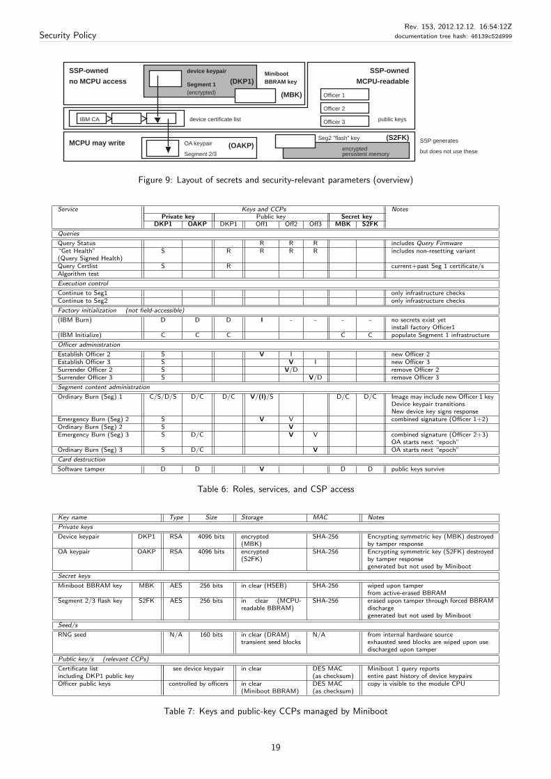
CSPs are internally generated by Miniboot, and are not exported outside the secure boundary. Officer identity, and otherCCPs, are imported/generated by Miniboot; some public data is shared with the module CPU, see Fig. 9. Certain CSPs aregenerated but not used by Miniboot, and they are owned by Segment 2/3 code, outside the scope of this policy.
Segment 0 state does not include secrets, as the module does not include authenticated Officer 0 commands. Note thatthis is a change from previous members of the 47xx family, where Miniboot 0 was involved with card recovery. We nolonger provide a capability to restore (“revive”) a module to functional—without secrets, obviously, but allowing factoryre-initialization—which was a dormant feature previously (was never exercised, per company policy).
Segment 1 has a device private key pair (“DKP1”), generated during card initialization, rolled over with subsequentSegment 1 updates (see Table 7). This private key serves as the card trust root, and it is the most valuable card secret. Itis stored encrypted with a Miniboot-owned AES key (“MBK”), which itself is actively erased in case of tamper.
The card also stores a public certificate chain, starting from its first device keypair (issued by the IBM factory CA). Queryingthis certificate list allows one to establish trust recursively in any current card-resident key (Fig. 2).
Segment 2/3 code offers public-key services (OA) similar to those of Segment 1, through a keypair referred to as OAkey(pair) (“OAKP”). When generated, the OA keypair is stored encrypted into MCPU-visible storage, together with itsSegment 2 flash-encryption key (“S2FK”). These keys are not used by Miniboot itself; MCPU code “owns” them. Oncegenerated, the OA keypair is issued a certificate by the current device keypair, pushed to the module CPU, then ignored byMiniboot. Segment 2/3 code may use these keys, which is outside the scope of this document.
Generating keys in Miniboot on behalf of the module CPU allows Miniboot to issue an DKP1/OAKP certificate, and to erasepersistent Segment 2/3 secrets even without a cooperating Segment 2/3 entity. If the S2FK is replaced, all persistent dataencrypted by previous Segment 2/3 code is indirectly lost.
For Layer 1 through Layer 3, the CSP/CCP consists of:
• identity of the officer controlling the layer
• code residing in this layer, i.e, the segment hash identifying layer code contents. This code is identified through ahash, but itself is not a secret.
• state that this program has accumulated in persistent memory
Compound segment state is uniquely determined by the set of the above parameters. Officer public keys are imported tothe module. Status fields and segment state are managed by Miniboot, some of them are returned in the Segment 1 query.
Officer identity is represented through a public key stored on behalf of the respective officer. An officer must be able todemonstrate possession of the corresponding private key by signing commands. Officer identities may be queried throughthe Segment 1 status query, returning registered public keys. Officer 2/3 identities are imported in the “Establish Owner”command of the corresponding segment and removed by the “Surrender Owner” commands. (Segment 1 does not haveequivalents, as Miniboot 1 is always retained as an active entity.)
If present, Segment 2/3 state includes Layer 2 private key(s) noted above. These keys resemble Segment 1 keypairs: theyare internally generated, are not exportable by Miniboot, but may be their exportable public-key certificates may be queried.These keys may be generated and used through an internal OA interface that mimics the public-key services of Miniboot 1,in the Segment 2. The default IBM code provides these interfaces; it supports key generation, certificate (list) export, andsigning, for a suitable Segment 3 application. These Segment 2/3 capabilities are outside the scope of this FIPS validation,but are mentioned here for completeness, since they are derived from Segment 1 key objects.
Control of code is obviously also critical to module security. Segment contents are updated in sync with state and officeridentity. Table 6 summarizes administrator-level actions performed by Segment 0 and 1. CSP/CCP actions show thefollowing actions: parameters are created (C) or imported (I), they may be subsequently read (R), may verify signatures(V), or may themselves sign (S). Finally, parameters may be destroyed (D). In case of certain transactions, the sequenceis indicated, such as when a device keypair gets updated: C/S/D/S shows a new key is created ; the previous one signs it,the previous private key gets destroyed, and the new key signs the final response.
The following notes apply to Table 6:
1. The User is entirely controlled by the Segment 3 officer, and actions of Officer 3 apply to the User as well. The Userentity is incapable of influencing infrastructure. In a typical application, the module-resident portion of a CSP—suchas PKCS#11—would belong to the User role.
Note that such User-level entities may further divide their responsibilities to API Security Officer and User; thesedistinctions are outside the scope of Miniboot policy.
17
Security PolicyRev. 153, 2012.12.12. 16:54:12Z
documentation tree hash: 46139c52d999
2. Certain Miniboot actions, which are never performed in the field, are included for completeness. Control operationsbefore the module is released are relevant, even if they may not be invoked during regular operations.
3. If Segment 3’s secrets (persistent objects) are labeled to distrust Segment 1–2 configuration changes, certain changesdestroy Segment 3 persistent data.
4. All secrets are destroyed by hardware-managed tamper response. Tamper does not need/use Miniboot functionality.
5. Commands’ responses are signed by the device keypair.
6. Use of non-Officer public keys is outside Miniboot control, and not represented.
The available functions affect following CSPs and CCPs (see the more detailed listing under 6.6):
Query Status Read infrastructure status, including layer owners. Reset the module CPU (OS/application).
Query Status/Noreset (“Query Firmware”) Read infrastructure status, including layer owners. Do not reset module CPU.
Query Signed Health (“Get Health”) Read status, including owner identities and public keys. Resets module CPU.
Query Signed Health/Noreset Read status, including owner identities and public keys. Do not reset module CPU.
Algorithm test Hashes host-supplied data as an, interactive communications/infrastructure selftest. Does not access CSPs.
Continue to Segment 1 advance into Segment 1 code if status permits
Continue to Segment 2 advance into Segment 2 code if possible. POST 2 selftest must have completed successfully.
IBM Burn Load Layer 1 (owner) public key and initial code; clear all internal persistent storage.
This command starts the card lifecycle, after manufacturing tests have passed. Hardware controls prohibit it, oncethe card has completed initialization. We mention it here only for completeness.
IBM Initialize Generate device (Layer 1) keypair; write new certificate; clear Layer 2 and 3 parameters and structures
Note that this command is only available in the factory, and mentioned here only for completeness.
Establish Officer 2 register new Officer 2 (i.e., public key)
Establish Officer 3 register new Officer 3 (i.e., public key)
Surrender Officer 2 Clear Layer 2 and 3 parameters, public keys, and persistent data
Surrender Officer 3 Clear Layer 3 parameters, public key, and persistent data
Ordinary Burn 1 Load Layer 1 (owner) public key; optionally clear Layer 2 and 3 parameters and persistent data, as definedby Segment 2/3 persistent object definitions
Ordinary Burn 2 optionally clear Layer 3 parameters and persistent data; write Segment 2 code (over previous active one)
Emergency Burn 2 clear Layer 2 and 3 persistent data; write Segment 2 code
Ordinary Burn 3 write Segment 3 code (over previous active one)
Emergency Burn 3 write Segment 3 code; clear Layer 3 persistent data
Software-induced tamper destroy all card-resident secrets, rendering the card unusable.
Note that this command must be targeted to particular cards, requires IBM cooperation to create (instances areunique), and is therefore not expected to be used during the lifetime of a typical deployment.
6.6 Queries and Commands
Table 5 summarizes queries and commands that Miniboot offers. Note that “Officer 0”—IBM manufacturing—does notinteract with cards, once they have left the factory. The “User”, understood as the application-level entity controlling card-resident applications, interacts with the card under controlled circumstances, and can not influence infrastructure state.(We disregard infrastructure-level or physical control, such as the ability to remove card power, for these purposes.)
Lacking direct Officer 0 and User interaction, they are present in the table without indicated actions. This is not a mistake.
18
Security PolicyRev. 153, 2012.12.12. 16:54:12Z
documentation tree hash: 46139c52d999
device keypair
(DKP1)Segment 1
(encrypted)
persistent memoryencrypted(OAKP)OA keypair
Segment 2/3
BBRAM key
Miniboot
(MBK)
SSP generates
but does not use these
Officer 3
Officer 2
Officer 1
device certificate list
no MCPU access
MCPU may write
SSP-owned
Seg2 "flash" key (S2FK)
public keys
SSP-owned
MCPU-readable
IBM CA
Figure 9: Layout of secrets and security-relevant parameters (overview)
Service Keys and CCPs NotesPrivate key Public key Secret key
DKP1 OAKP DKP1 Off1 Off2 Off3 MBK S2FK
Queries
Query Status R R R includes Query Firmware“Get Health”(Query Signed Health)
S R R R R includes non-resetting variant
Query Certlist S R current+past Seg 1 certificate/sAlgorithm test
Execution control
Continue to Seg1 only infrastructure checksContinue to Seg2 only infrastructure checks
Factory initialization (not field-accessible)
(IBM Burn) D D D I - - - - no secrets exist yetinstall factory Officer1
(IBM Initialize) C C C C C populate Segment 1 infrastructure
Officer administration
Establish Officer 2 S V I new Officer 2Establish Officer 3 S V I new Officer 3Surrender Officer 2 S V/D remove Officer 2Surrender Officer 3 S V/D remove Officer 3
Segment content administration
Ordinary Burn (Seg) 1 C/S/D/S D/C D/C V/(I)/S D/C D/C Image may include new Officer 1 keyDevice keypair transitionsNew device key signs response
Emergency Burn (Seg) 2 S V V combined signature (Officer 1+2)Ordinary Burn (Seg) 2 S VEmergency Burn (Seg) 3 S D/C V V combined signature (Officer 2+3)
OA starts next “epoch”Ordinary Burn (Seg) 3 S D/C V OA starts next “epoch”
Card destruction
Software tamper D D V D D public keys survive
Table 6: Roles, services, and CSP access
Key name Type Size Storage MAC Notes
Private keys
Device keypair DKP1 RSA 4096 bits encrypted(MBK)
SHA-256 Encrypting symmetric key (MBK) destroyedby tamper response
OA keypair OAKP RSA 4096 bits encrypted(S2FK)
SHA-256 Encrypting symmetric key (S2FK) destroyedby tamper responsegenerated but not used by Miniboot
Secret keys
Miniboot BBRAM key MBK AES 256 bits in clear (HSEB) SHA-256 wiped upon tamperfrom active-erased BBRAM
Segment 2/3 flash key S2FK AES 256 bits in clear (MCPU-readable BBRAM)
SHA-256 erased upon tamper through forced BBRAMdischargegenerated but not used by Miniboot
Seed/s
RNG seed N/A 160 bits in clear (DRAM)transient seed blocks
N/A from internal hardware sourceexhausted seed blocks are wiped upon usedischarged upon tamper
Public key/s (relevant CCPs)
Certificate listincluding DKP1 public key
see device keypair in clear DES MAC(as checksum)
Miniboot 1 query reportsentire past history of device keypairs
Officer public keys controlled by officers in clear(Miniboot BBRAM)
DES MAC(as checksum)
copy is visible to the module CPU
Table 7: Keys and public-key CCPs managed by Miniboot
19
Security PolicyRev. 153, 2012.12.12. 16:54:12Z
documentation tree hash: 46139c52d999
Miniboot 0 Queries Miniboot 0 provides two versions of a “field” query:
• Query: Status This query returns general status information about the card software versions, card identification. Themodule CPU is reset while performing the query.
• Query: Status/Noreset Return status information without resetting an module CPU. Added to be able to serve queriesfrom modern host code, which is aware of the coexistence of the SSP and the module CPU.
Legacy applications, if unaware of enhancements since the 4764 family, will continue executing, since they issue a resettingquery variant (by construction: the single processor was reset while Miniboot was being queried). New applications maystart to issue “Noreset” variants of queries, without impacting execution on the module CPU.
Miniboot 0 Commands Miniboot 0 provides these commands:
• IBM Burn. Install a new Program 1 and public key for Officer 1, while still in the factory. This command allowsmanufacturing to initialize cards without assuming anything in Segment 1 or above.
Note that the IBM Burn command is not accessible once it left the factory. It is included for reference only.
• Continue. Transfer execution to Segment 1, if possible. Prohibited if integrity check on Segment 1 failed.
In an end-user environment, Miniboot 0 can issue only the “Continue” command to advance execution to Segment 1.
Miniboot 1 Queries Miniboot 1 provides these queries:
• Query: Get Health. The requester selects and sends a nonce. The card returns a signed response containing generalhealth information:
– the same data as the Status query of Miniboot 0
– identifying information about code and owners in reliable segments
– host-supplied nonce to indicate freshness
The Get Health query resets the module CPU. This behavior is equivalent to that of the 4764 and previous generations.
• Query: Get Health/Noreset. Equivalent to the Get Health query, without resetting the module CPU, without impactingrunning Seg3 applications. An alias for this functionality is “Query: Firmware”.
• Query: Certlist. The card returns a signed response containing the certificate chain taking the card’s current publickey back to the IBM Factory CA (Certificate Authority).
• Algorithm test. Hash user-supplied data. Using a module to calculate unkeyed hashes is overkill; this service is usedby host drivers as an overall connectivity and functionality test. It passes data through all relevant interfaces, fromhost to hardware engines and back, and returns the SHA-256 hash of host data.
Miniboot 1 Commands Miniboot 1 provides these commands:
• IBM Initialize. While still in the factory: generate a device keypair, have it certified by the Factory CA, and set the“module is initialized” (factory “sticky bit”) active. This command is rejected if the card has been initialized.
The IBM Initialize command is not accessible in the field. It is included for reference only.
• Establish Owner n, for n > 1. Give an UNOWNED layer n to someone. Register a new public key as the officercontrolling Segment n.
Ownership may be established only if the segment is not claimed by any owner (i.e., is “UNOWNED”). The newowner’s public key is registered, segment state is upgraded to “OWNED BUT UNRELIABLE”. This state preventsexecution, but allows subsequent code loading. Miniboot does not execute code from such a segment.
Once the new owner loads code to the segment, its state is upgraded to “RUNNABLE”, indicating that segment owneridentity is known and the segment code has been written after verifying its signature. Once these two conditions aremet, execution may pass to this segment.
20
Security PolicyRev. 153, 2012.12.12. 16:54:12Z
documentation tree hash: 46139c52d999
• Surrender Owner n, for n > 1. Give up ownership of Layer n.
A prerequisite of surrendering ownership is that the segment is owned, since ownership of it is required to sign thecommand. The segment ownership indication is removed (segment reverts to “UNOWNED”), segment contents areflagged as not runnable. Just as with a segment before its contents are written first, Miniboot will not pass executionto such segments, even if their previous contents are not removed.
• Ordinary Burn n. Update Program n. The Segment 1 command replaces Segment 1 code, and may include asubsequent public key for Officer 1. Since the command replaces an active segment with another image, it only worksfor “reliable” segments—those with officers and firmware loaded. (Segment 1 is always reliable, if Miniboot runs.)
Documentation may refer to this command as “Remote Burn.” The command is signed by the originating officer.
• Emergency Burn n for n > 1. Install Program n for Officer n—without using current contents of Segment n.
This version, while overwriting Segment n, is controlled by Officer n− 1. It is used, for example, to recover the cardfrom lost officer keys, or other situations where the a layer wishes to override the officer controlling the lower trustlevel. It is also used during initial firmware loading, where obviously no previous image is present in flash.
Persistent objects may be flagged to survive an Emergency Burn, or be destroyed during the process (i.e., allow anofficer to restrict its secrets to that particular card configuration). This distinction is enforced by Miniboot 1, andOS/application officers may not influence it.
• Continue Continue execution to Segment 2, if possible. Possible only after POST 2 has reported that module CPUinfrastructure tests passed.
• Software-induced tamper Destroy card secrets, triggering a regular tamper response. This command must be targetedto specific cards, therefore its payload requires IBM cooperation to produce (as it must be signed by our factory CA).Most users will not need to utilize this command, but it may be useful in restricted environments where timelymodule destruction is desired, but may not be performed (such as due to lack of physical access).
Since our modules do not allow reinitialization, a successfully issued software-induced tamper is the last commandever executed by a particular module.
6.7 Overall Security Goals
The overall goal of this policy is to ensure that the following properties hold:
Safe Execution. Miniboot will not execute or pass control to code that depends on hardware that has failed.
Generally, modules react immediately to hardware faults, remaining consistent in the presence of transient failures.
Access to Secrets. Program n should have neither read nor write access to the secrets belonging to Program k < n.
Safe Zeroization. In case of attack or failure, the device will destroy the secrets belonging to Program n before an adversarycan access the memory where those secrets are stored.
Besides hardware tamper, such attacks may include (for k < n) loading of a Program k that Officer n does not trust.
Control of Software. Should layer n later change in any way other than demotion due to failure, some current Officer k(for k ≤ n) is responsible for that action, using his current authentication key.
Outbound Authentication. On-board applications can authenticate themselves to anyone. Suppose Alice knows a Layer 2private key certified back, through Miniboot on an untampered card, to IBM. if Bob trusts entities named in thiscertification chain, then Bob can conclude that Alice is the entity named in that last certificate (Fig. 2).
Trustworthy state. The module shall maintain the state of an officer’s program only while the module continuously main-tains an environment for that program that is verifiably trusted by that officer.
Minimal trust. The module shall not require officers to trust each other—or trust the hardware manufacturer—any morethan is necessary.
Data persistence. The module shall permit officers to retain their data across updates, where possible and reasonable.
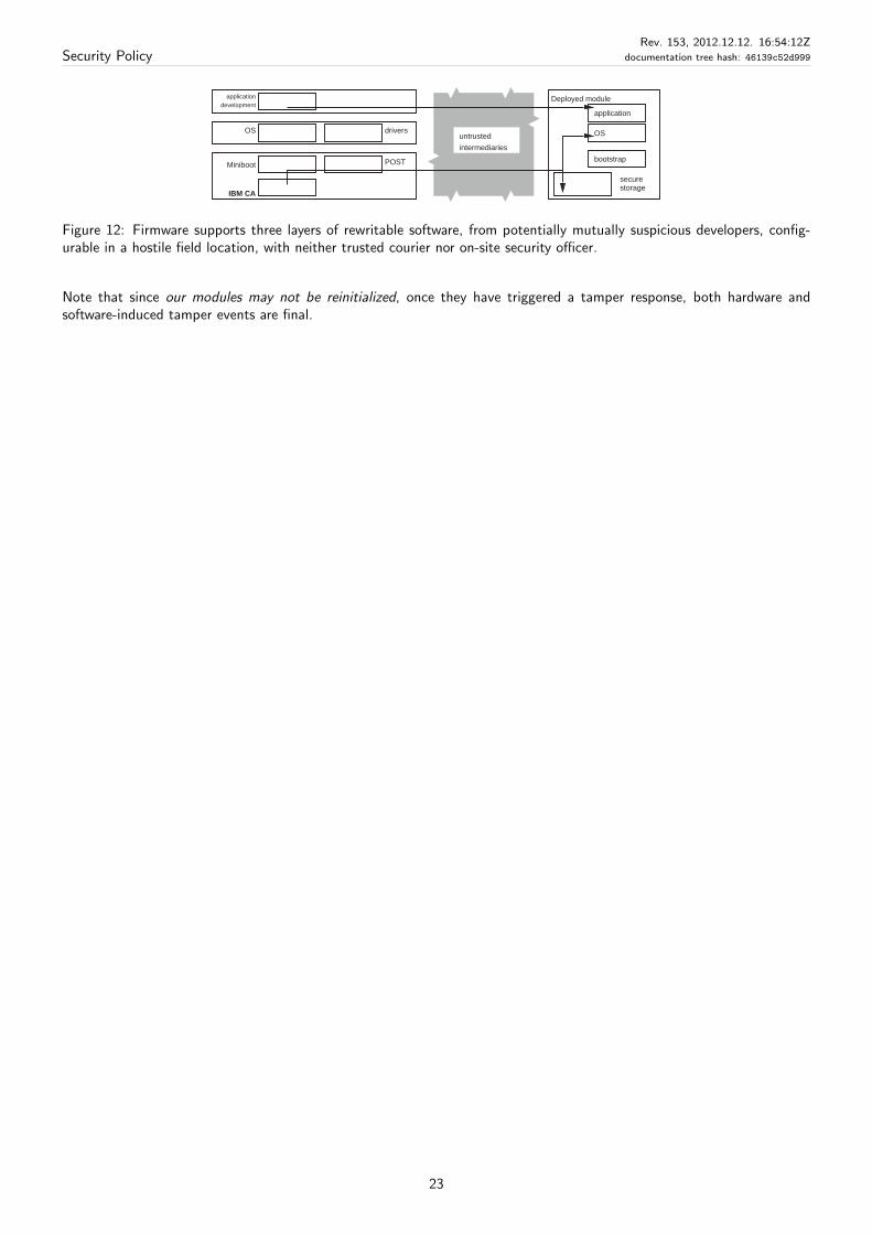
End-to-end secure code control. The module shall enable all rewritable software layers to be installed and maintained ina hostile field, without the use of trusted couriers or on-site security officers. See Fig. 12.
21
Security PolicyRev. 153, 2012.12.12. 16:54:12Z
documentation tree hash: 46139c52d999
In factory
initialization
under
In factory
uninitialized
Initialized
field-ready (maintenance)
(Dead)recoverable
failures
is runnable
Segment 1
non-recoverable
failures
misc. failures
IBM Burn
IBM Initialize
tamperuser-accessible states
Figure 10: Configurations and main flows of device initialization, specifically Segment 1
Owned
"unreliable"
Reliable
unrunnable
Unowned RunnableBurnEmergency
OwnerEstablish
Burn
Burn
(failures)(failures)(firmware update)
Surrender (segment) ownership
(distrust)
reliable (segment firmware loaded)(controlling officer registered)
Figure 11: Configurations and main flows for Segment n, for n > 1. One can “Burn” or “Emergency Burn” from any ofthe reliable states into Runnable.
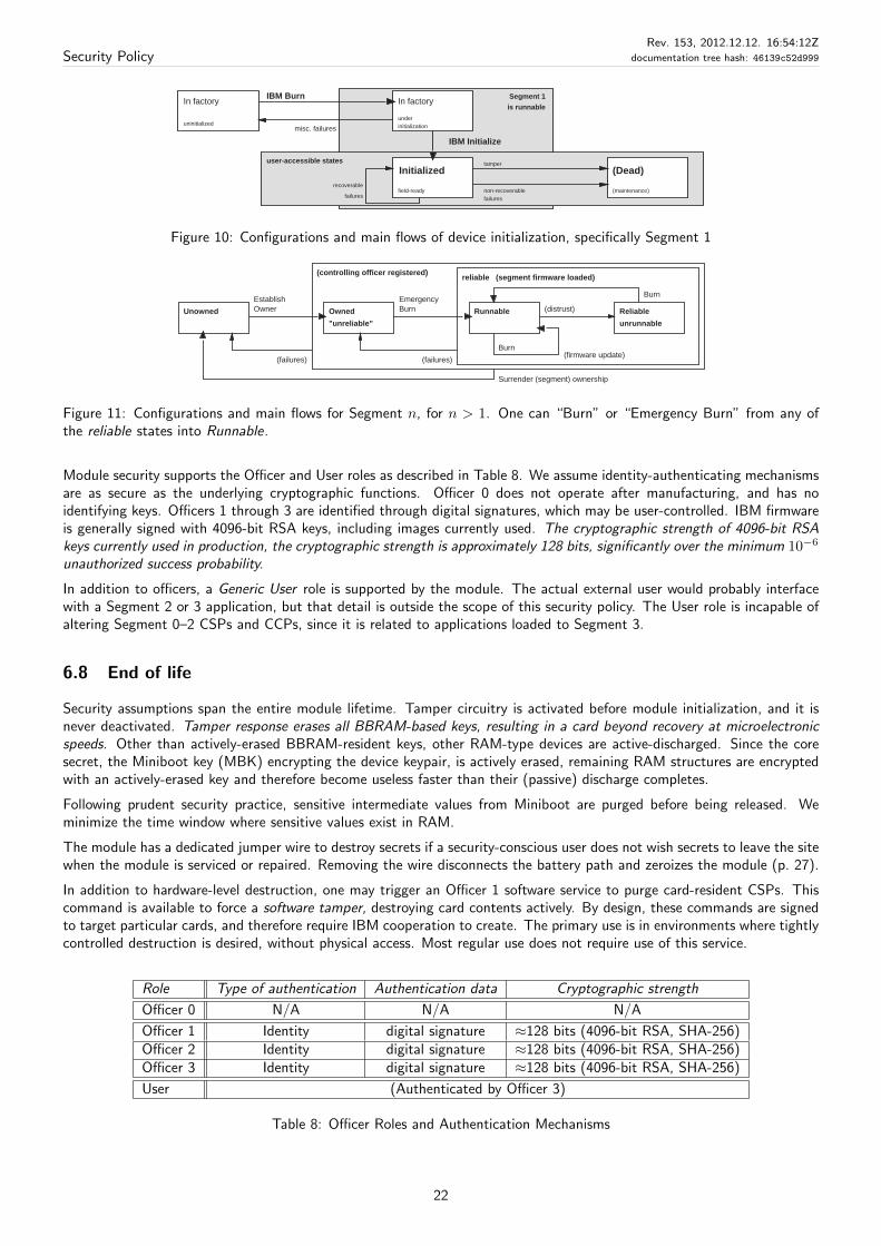
Module security supports the Officer and User roles as described in Table 8. We assume identity-authenticating mechanismsare as secure as the underlying cryptographic functions. Officer 0 does not operate after manufacturing, and has noidentifying keys. Officers 1 through 3 are identified through digital signatures, which may be user-controlled. IBM firmwareis generally signed with 4096-bit RSA keys, including images currently used. The cryptographic strength of 4096-bit RSAkeys currently used in production, the cryptographic strength is approximately 128 bits, significantly over the minimum 10−6
unauthorized success probability.
In addition to officers, a Generic User role is supported by the module. The actual external user would probably interfacewith a Segment 2 or 3 application, but that detail is outside the scope of this security policy. The User role is incapable ofaltering Segment 0–2 CSPs and CCPs, since it is related to applications loaded to Segment 3.
6.8 End of life
Security assumptions span the entire module lifetime. Tamper circuitry is activated before module initialization, and it isnever deactivated. Tamper response erases all BBRAM-based keys, resulting in a card beyond recovery at microelectronicspeeds. Other than actively-erased BBRAM-resident keys, other RAM-type devices are active-discharged. Since the coresecret, the Miniboot key (MBK) encrypting the device keypair, is actively erased, remaining RAM structures are encryptedwith an actively-erased key and therefore become useless faster than their (passive) discharge completes.
Following prudent security practice, sensitive intermediate values from Miniboot are purged before being released. Weminimize the time window where sensitive values exist in RAM.
The module has a dedicated jumper wire to destroy secrets if a security-conscious user does not wish secrets to leave the sitewhen the module is serviced or repaired. Removing the wire disconnects the battery path and zeroizes the module (p. 27).
In addition to hardware-level destruction, one may trigger an Officer 1 software service to purge card-resident CSPs. Thiscommand is available to force a software tamper, destroying card contents actively. By design, these commands are signedto target particular cards, and therefore require IBM cooperation to create. The primary use is in environments where tightlycontrolled destruction is desired, without physical access. Most regular use does not require use of this service.
Role Type of authentication Authentication data Cryptographic strength
Officer 0 N/A N/A N/A
Officer 1 Identity digital signature ≈128 bits (4096-bit RSA, SHA-256)Officer 2 Identity digital signature ≈128 bits (4096-bit RSA, SHA-256)Officer 3 Identity digital signature ≈128 bits (4096-bit RSA, SHA-256)
User (Authenticated by Officer 3)
Table 8: Officer Roles and Authentication Mechanisms
22
Security PolicyRev. 153, 2012.12.12. 16:54:12Z
documentation tree hash: 46139c52d999
application
OS
bootstrap
securestorage
driversOS
development
application Deployed module
IBM CA
Miniboot POST
untrusted
intermediaries
Figure 12: Firmware supports three layers of rewritable software, from potentially mutually suspicious developers, config-urable in a hostile field location, with neither trusted courier nor on-site security officer.
Note that since our modules may not be reinitialized, once they have triggered a tamper response, both hardware andsoftware-induced tamper events are final.
23
Security PolicyRev. 153, 2012.12.12. 16:54:12Z
documentation tree hash: 46139c52d999
7 Module Configuration for FIPS 140–2 Compliance
7.1 FIPS 140-related definitions
This FIPS 140 validation addresses only hardware, and Layer 0 and Layer 1 of the software—the generic device firmware,as shipped.
For the purposes of this FIPS 140–2 validation, “Officer 0” is the logical owner of Miniboot 0. Since this officer operates onlyin the secure factory, most of its operations are therefore out of the scope of this policy, and are only indirectly referenced.
Layer 1 includes all infrastructure, including low-level programs, and configuration. The segment image may include bitfilesfor multiple hardware components–i.e., FPGA/SSP–as a single logical unit.
Layers 2 and 3—OS/application code—are excluded from this FIPS 140 validation effort. In certain cases, Segment 2 and3 contents are explicitly mentioned in the context of Segment 0 and 1, where necessary. POST 2, logically controlled bySegment 1, is included in the validation set, since it is access-controlled by Miniboot 1, even if executed on the module CPU.Excluding module CPU code from the current validation allows other OS/application code to get separately validated onthe same infrastructure, not tying card usage, for example, to the default IBM-supplied OS.
The “User” role can access a subset of Segment 3 capabilities, and can’t directly influence module configuration. Useractions are therefore discussed in the context of Segment 3 officer actions. In most environments, external users wouldinteract with interfaces provided by the User role, through applications loaded under Segment 3 officer’s control.
7.2 Hardware and firmware identifiers
Firmware configuration is primarily characterized by Miniboot revision; FPGA, POST 1, and POST 2 versions are alsoincluded in “module firmware configuration”. Configurations are officially tracked through Segment hashes and not individualMiniboot, FPGA, or POST revisions. We use leading digits of the Segment 1 hash as firmware identifier (“FWID”) to brieflycharacterize Segment 1 firmware contents. Host administrator utilities generally report the entire hash.
The feature-table below shows compliant combinations of hardware and firmware.
As some hardware versions may use binary compatible firmware, the same segment hashes may appear multiple times; theyare shown with each hardware revision capable of running them.
Hardware FWID Segment 1 hash (SHA-256)
45D6048 e1ced7a0 e1ced7a0 e835fb37 52ca2d21 b6a834f4 e582c2f3 1199c402 4618b38f ab1f87cb
41D8612 e1ced7a0 e1ced7a0 e835fb37 52ca2d21 b6a834f4 e582c2f3 1199c402 4618b38f ab1f87cb
To be in FIPS mode, a module must have been loaded with the above validated Segment 1 revision. Security officersmust verify hardware part number during installation. Tools report the PN of the entire card assembly, not just that of themodule. These numbers are recognizably close, by construction: as an example, card 45D6047 containing module 45D6048.Module hardware PN is displayed separately on packaging for easier tracking.
Host drivers SHOULD provide a method to query the Segment 1 hash, issuing the Miniboot 1 Get Health query; this detailis platform-dependent. Platform-specific documentation describes the necessary commands or tools; the development kitalso describes how the same structures may be obtained by host software.
Note that segment hashes do not correspond to the hash of the actual image file: it is calculated over a subset of the signedcommands. Therefore, utilities such as sha256sum may not be used to identify contents of an image file directly.
7.2.1 Updates new to this validation
Compared to the original,evaluated version (FWID e1ced7a0 on hardware 45D6048),the following changed versionhas beenreleased:
1. hardware component replacements: functionally identical,qualified lead-free components replace some of the chipswithin the security module. (The entire assembly is lead-free/RoHS compliant after these replacements.)
Supported firmware versions,and by implication services,are identical to the original release; only hardware componentschange.)
24
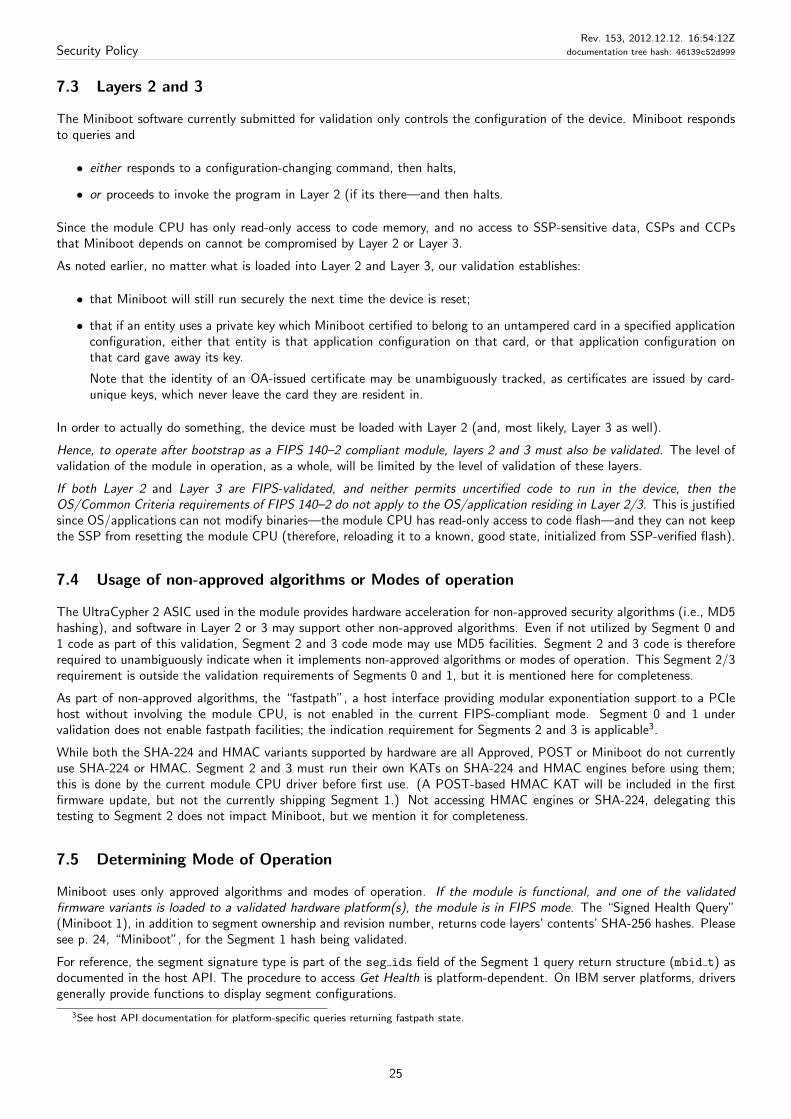
Security PolicyRev. 153, 2012.12.12. 16:54:12Z
documentation tree hash: 46139c52d999
7.3 Layers 2 and 3
The Miniboot software currently submitted for validation only controls the configuration of the device. Miniboot respondsto queries and
• either responds to a configuration-changing command, then halts,
• or proceeds to invoke the program in Layer 2 (if its there—and then halts.
Since the module CPU has only read-only access to code memory, and no access to SSP-sensitive data, CSPs and CCPsthat Miniboot depends on cannot be compromised by Layer 2 or Layer 3.
As noted earlier, no matter what is loaded into Layer 2 and Layer 3, our validation establishes:
• that Miniboot will still run securely the next time the device is reset;
• that if an entity uses a private key which Miniboot certified to belong to an untampered card in a specified applicationconfiguration, either that entity is that application configuration on that card, or that application configuration onthat card gave away its key.
Note that the identity of an OA-issued certificate may be unambiguously tracked, as certificates are issued by card-unique keys, which never leave the card they are resident in.
In order to actually do something, the device must be loaded with Layer 2 (and, most likely, Layer 3 as well).
Hence, to operate after bootstrap as a FIPS 140–2 compliant module, layers 2 and 3 must also be validated. The level ofvalidation of the module in operation, as a whole, will be limited by the level of validation of these layers.
If both Layer 2 and Layer 3 are FIPS-validated, and neither permits uncertified code to run in the device, then theOS/Common Criteria requirements of FIPS 140–2 do not apply to the OS/application residing in Layer 2/3. This is justifiedsince OS/applications can not modify binaries—the module CPU has read-only access to code flash—and they can not keepthe SSP from resetting the module CPU (therefore, reloading it to a known, good state, initialized from SSP-verified flash).
7.4 Usage of non-approved algorithms or Modes of operation
The UltraCypher 2 ASIC used in the module provides hardware acceleration for non-approved security algorithms (i.e., MD5hashing), and software in Layer 2 or 3 may support other non-approved algorithms. Even if not utilized by Segment 0 and1 code as part of this validation, Segment 2 and 3 code mode may use MD5 facilities. Segment 2 and 3 code is thereforerequired to unambiguously indicate when it implements non-approved algorithms or modes of operation. This Segment 2/3requirement is outside the validation requirements of Segments 0 and 1, but it is mentioned here for completeness.
As part of non-approved algorithms, the “fastpath”, a host interface providing modular exponentiation support to a PCIehost without involving the module CPU, is not enabled in the current FIPS-compliant mode. Segment 0 and 1 undervalidation does not enable fastpath facilities; the indication requirement for Segments 2 and 3 is applicable3.
While both the SHA-224 and HMAC variants supported by hardware are all Approved, POST or Miniboot do not currentlyuse SHA-224 or HMAC. Segment 2 and 3 must run their own KATs on SHA-224 and HMAC engines before using them;this is done by the current module CPU driver before first use. (A POST-based HMAC KAT will be included in the firstfirmware update, but not the currently shipping Segment 1.) Not accessing HMAC engines or SHA-224, delegating thistesting to Segment 2 does not impact Miniboot, but we mention it for completeness.
7.5 Determining Mode of Operation
Miniboot uses only approved algorithms and modes of operation. If the module is functional, and one of the validatedfirmware variants is loaded to a validated hardware platform(s), the module is in FIPS mode. The “Signed Health Query”(Miniboot 1), in addition to segment ownership and revision number, returns code layers’ contents’ SHA-256 hashes. Pleasesee p. 24, “Miniboot”, for the Segment 1 hash being validated.
For reference, the segment signature type is part of the seg ids field of the Segment 1 query return structure (mbid t) asdocumented in the host API. The procedure to access Get Health is platform-dependent. On IBM server platforms, driversgenerally provide functions to display segment configurations.
3See host API documentation for platform-specific queries returning fastpath state.
25

Security PolicyRev. 153, 2012.12.12. 16:54:12Z
documentation tree hash: 46139c52d999
Host drivers are assumed to store query results and make them available to higher-level—application—users. User applica-tions/administrators should be able to unambiguously verify the configuration of module segments. Host driver implemen-tation, while outside the scope of this specification, should provide a convenient way of querying card configuration, sincemost likely user application won’t interface to Miniboot directly.
26
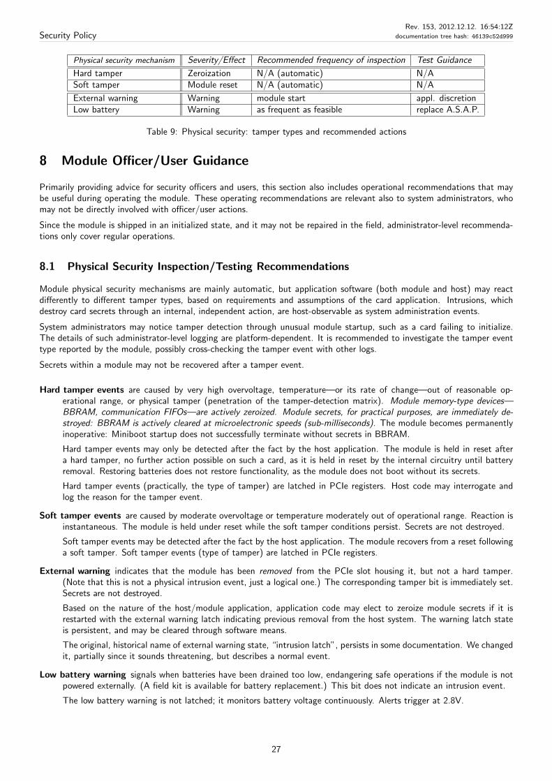
Security PolicyRev. 153, 2012.12.12. 16:54:12Z
documentation tree hash: 46139c52d999
Physical security mechanism Severity/Effect Recommended frequency of inspection Test Guidance
Hard tamper Zeroization N/A (automatic) N/ASoft tamper Module reset N/A (automatic) N/A
External warning Warning module start appl. discretionLow battery Warning as frequent as feasible replace A.S.A.P.
Table 9: Physical security: tamper types and recommended actions
8 Module Officer/User Guidance
Primarily providing advice for security officers and users, this section also includes operational recommendations that maybe useful during operating the module. These operating recommendations are relevant also to system administrators, whomay not be directly involved with officer/user actions.
Since the module is shipped in an initialized state, and it may not be repaired in the field, administrator-level recommenda-tions only cover regular operations.
8.1 Physical Security Inspection/Testing Recommendations
Module physical security mechanisms are mainly automatic, but application software (both module and host) may reactdifferently to different tamper types, based on requirements and assumptions of the card application. Intrusions, whichdestroy card secrets through an internal, independent action, are host-observable as system administration events.
System administrators may notice tamper detection through unusual module startup, such as a card failing to initialize.The details of such administrator-level logging are platform-dependent. It is recommended to investigate the tamper eventtype reported by the module, possibly cross-checking the tamper event with other logs.
Secrets within a module may not be recovered after a tamper event.
Hard tamper events are caused by very high overvoltage, temperature—or its rate of change—out of reasonable op-erational range, or physical tamper (penetration of the tamper-detection matrix). Module memory-type devices—BBRAM, communication FIFOs—are actively zeroized. Module secrets, for practical purposes, are immediately de-stroyed: BBRAM is actively cleared at microelectronic speeds (sub-milliseconds). The module becomes permanentlyinoperative: Miniboot startup does not successfully terminate without secrets in BBRAM.
Hard tamper events may only be detected after the fact by the host application. The module is held in reset aftera hard tamper, no further action possible on such a card, as it is held in reset by the internal circuitry until batteryremoval. Restoring batteries does not restore functionality, as the module does not boot without its secrets.
Hard tamper events (practically, the type of tamper) are latched in PCIe registers. Host code may interrogate andlog the reason for the tamper event.
Soft tamper events are caused by moderate overvoltage or temperature moderately out of operational range. Reaction isinstantaneous. The module is held under reset while the soft tamper conditions persist. Secrets are not destroyed.
Soft tamper events may be detected after the fact by the host application. The module recovers from a reset followinga soft tamper. Soft tamper events (type of tamper) are latched in PCIe registers.
External warning indicates that the module has been removed from the PCIe slot housing it, but not a hard tamper.(Note that this is not a physical intrusion event, just a logical one.) The corresponding tamper bit is immediately set.Secrets are not destroyed.
Based on the nature of the host/module application, application code may elect to zeroize module secrets if it isrestarted with the external warning latch indicating previous removal from the host system. The warning latch stateis persistent, and may be cleared through software means.
The original, historical name of external warning state, “intrusion latch”, persists in some documentation. We changedit, partially since it sounds threatening, but describes a normal event.
Low battery warning signals when batteries have been drained too low, endangering safe operations if the module is notpowered externally. (A field kit is available for battery replacement.) This bit does not indicate an intrusion event.
The low battery warning is not latched; it monitors battery voltage continuously. Alerts trigger at 2.8V.
27

Security PolicyRev. 153, 2012.12.12. 16:54:12Z
documentation tree hash: 46139c52d999
8.2 Module initialization and delivery
The module is initialized at the factory. Internal controls guarantee that each one may be initialized only once, thereforethere are no field initialization requirements, other than platform-specific ones for installation of PCIe cards.
Once a module has been delivered, its configuration should be logged, to verify that it is fully operational and loaded by anapproved code level. Application-specific details of this verification are available outside this policy.
8.3 Miscellaneous
Note that the module is very sensitive to environmental conditions. Environmental requirements, specified in a platform-dependent manner, are safely within the range encountered a well-managed and reliable enterprise computing environment.
Security officers and users should verify module configuration before utilizing its services. If the card identity (device key orserial number) does not match security officer/user expectations, applications should investigate the discrepancy and reactin a prudent fashion. Module code configuration, returned by a Segment 1 query for all segments, is public.
28
Security PolicyRev. 153, 2012.12.12. 16:54:12Z
documentation tree hash: 46139c52d999
Model Hardware (external bus type) Physical security Overall Certificateof module
4758 family
4758 Model 1 PCI Level 4 Level 4 Nr. 35
4758 Model 13 PCI Level 3 Level 3 Nr. 81
4758 Model 2 PCI Level 4 Level 4 Nr. 116
4758 Model 23 PCI Level 3 Level 3 Nr. 117
4764 variants
4764–001 PCI-X Level 4 Level 4 Nr. 524
4764–001 (updates) PCI-X Level 4 Level 4 Nr. 661
4765 family
4765 PCI Express (x4) Level 4 Level 4 Nr. 1505
4765 (updates) PCI Express (x4) Level 4 Level 4 —
Table 10: Overview of 47xx product families
9 Predecessors: the 4758 and 4764 families
The first member of the 4758 card family was introduced in 1997. In 1998, the foundational hardware and software receivedthe world’s first FIPS 140-1 Security Level 4 validation. Subsequently, the Security Level 3 Model 13 was introduced.
In 2000, IBM introduced two additional members of this family: the Model 2, and the Model 23. These devices consist ofthe follow-on “Model 2” device, with differing levels of physical security. These models introduced outbound authentication,the capability of a card to authenticate itself to external parties.
4764 variants The 4764, introduced in 2003, is functionally very similar to the Model 2 4758 with enhanced infrastructurecapabilities, in terms of performance, enhanced capabilities of its PCIX interface, and RAS features. Several variants of thisfamily exist with mainly hardware variations, and little user-visible firmware differences.
Firmware capabilities of 4764 releases correspond to earlier 4758’s; a few additional services have been introduced forhardware. The main functional difference is processor remap, and similar functionality-transparent reorganization.
29
Security PolicyRev. 153, 2012.12.12. 16:54:12Z
documentation tree hash: 46139c52d999
10 Glossary
CA Certificate Authority, in the Miniboot case, a module in the factory issuing certificates for Miniboot on new cards
CCPs are card configuration parameters, security-critical configuration state of a module, which is not confidential. Suchcritical information includes segment code and ownership (i.e., officer public keys).
EDC Error Detection Code.
Device keypair is a device-specific public-key keypair generated and retained by Segment 1. It is non-exportable, traceableback to the IBM factory CA through a certificate chain, and may be used by external parties to verify the identity ofa module, through outbound authentication (OA).
Firmware identifier is an unambiguous status identifier (“Segment 1 hash”), used to quickly summarize firmware contents.It is the SHA-256 hash of firmware contents, possibly including hardware, such as an FPGA bitfile.
Segments are identified by their own segment hashes, but this document only specifies Segment 1. Modules loadedwith validated Segment 2 and 3 must specify their specific validated configurations.
FWID Abbreviation of Firmware identifier
HLM Hardware Lock Microcontroller, a dedicated microcontroller which assisted previous 47xx generations with accesscontrol and management of persistent storage.
While current generations no longer contain an actual HLM controller, some of the relevant functionality has beenretained. Documentation refers to these features as “HLM (infrastructure)” for historical reasons. circuitry, withinthe “high-speed erase BBRAM” (HSEB).
HSEB High-speed erase BBRAM, a dedicated BBRAM chip actively erased upon tamper. The most valuable Minibootsecrets reside within this region, which is wiped within milliseconds of detecting a tamper event.
KAT Known Answer Test
Miniboot software component of module firmware.
Miniboot functionality, together with POST, roughly corresponds to those of a system BIOS in PCs, with obviousadditions to cover cryptographic functionality, module-specific hardware, and act as the module security controller.
OA Outbound Authentication, infrastructure capable of signing by a card-resident, non-exportable private key.
External parties, including other modules, can verify that signed content has been generated by untampered modulefirmware (Segment 1). An extension allows OA to manage private keys for OS or applications (Segment 2 or 3).
PCIe PCI Express, the external interface of our module (also abbreviated as PCI-E).
PN Part Number
POST Power-On Self-Test, infrastructure tests resident in ROM and flash.
RAS Abbreviation of Reliability, Availability, Serviceability
SSP Security Service Processor, a dedicated processor executing Miniboot and most of POST (i.e., all privileged code).
Segment 1F Segment 1F is the rewritable part of card infrastructure, including the FPGA programming file, and POST 2,all protected as part of Segment 1. Used only when the FPGA bitfile is explicitly mentioned in Segment 1 operations.
Policy revision: 153, last archived: 2012.12.12. 16:54:12 (UTC)
Documentation tree hash: 46139c52d999 (pass 2), check-in by user tvi (Tamas Visegrady).
30