IBM Corporation 4768 Cryptographic Coprocessor Security ... · The physical form of the Module is...
23
Copyright IBM Corporation, 28 August 2019 Document Version SP 1.14 Page 1 of 23 Public Material – May be reproduced only in its original entirety (without revision). IBM Corporation 4768 Cryptographic Coprocessor Security Module Non-Proprietary Security Policy IBM Advanced Cryptographic Hardware Development IBM Research - Zurich IBM Development – Lexington, Poughkeepsie, Boeblingen
Transcript of IBM Corporation 4768 Cryptographic Coprocessor Security ... · The physical form of the Module is...
Copyright IBM Corporation, 28 August 2019 Document Version SP 1.14 Page 1 of 23 Public Material – May be reproduced only in its original entirety (without revision).
IBM Corporation 4768 Cryptographic Coprocessor Security Module
Non-Proprietary Security Policy
IBM Advanced Cryptographic Hardware Development IBM Research - Zurich IBM Development – Lexington, Poughkeepsie, Boeblingen

Copyright IBM Corporation, 28 August 2019 Document Version SP 1.14 Page 2 of 23 Public Material – May be reproduced only in its original entirety (without revision).
Table of Contents
1 Document History ............................................................................................................ 5
2 Introduction .................................................................................................................... 6
2.1 Hardware and Physical Cryptographic Boundary .........................................................................8 2.2 Firmware and Logical Cryptographic Boundary ...........................................................................9 2.3 Mode of Operation .................................................................................................................... 10
3 Cryptographic Functionality ........................................................................................... 11
3.1 Critical Security Parameters (CSP) ............................................................................................. 12 3.2 Public Keys ................................................................................................................................. 13
4 Roles, Authentication and Services ................................................................................ 13
4.1 Assumption of Roles .................................................................................................................. 13 4.2 Authentication Methods ........................................................................................................... 14 4.3 Services ...................................................................................................................................... 14 4.4 Services cross-reference table .................................................................................................. 16
5 Self-tests ........................................................................................................................ 17
6 Physical Security Policy .................................................................................................. 19
7 Operational Environment .............................................................................................. 21
8 Mitigation of Other Attacks Policy ................................................................................. 21
9 Security Rules and Guidance .......................................................................................... 21
10 References and Definitions ............................................................................................ 22

Copyright IBM Corporation, 28 August 2019 Document Version SP 1.14 Page 3 of 23 Public Material – May be reproduced only in its original entirety (without revision).
List of Tables Table 1 – Cryptographic Module Configurations .......................................................................................... 6 Table 2 – Security Level of Security Requirements ....................................................................................... 7 Table 3 – Physical Ports and Interfaces ......................................................................................................... 9 Table 4 – Approved Cryptographic Functions ............................................................................................. 11 Table 5 – Non-Approved but Allowed Cryptographic Functions ................................................................ 12 Table 6 – Critical Security Parameters (CSPs) ............................................................................................. 12 Table 7 - Public Keys .................................................................................................................................... 13 Table 8 - Role Description ........................................................................................................................... 13 Table 9 - Authentication Method................................................................................................................ 14 Table 10 – Authenticated Services .............................................................................................................. 14 Table 11 – Unauthenticated Services ......................................................................................................... 15 Table 12 – Services cross-reference ............................................................................................................ 16 Table 13 – Power-on Self-tests ................................................................................................................... 18 Table 14 – Conditional Self-tests ................................................................................................................ 19 Table 15 – Physical Security Tamper Types and Recommended Actions ................................................... 20 Table 16 – References ................................................................................................................................. 22 Table 17 – Acronyms and Definitions ......................................................................................................... 22
Copyright IBM Corporation, 28 August 2019 Document Version SP 1.14 Page 4 of 23 Public Material – May be reproduced only in its original entirety (without revision).
List of Figures
Figure 1 – 4768-001 Module ......................................................................................................................... 8 Figure 2 – 4768-001 Block Diagram ............................................................................................................ 10 Figure 3 – Module Software Architecture – Example Usage ...................................................................... 10
Copyright IBM Corporation, 28 August 2019 Document Version SP 1.14 Page 5 of 23 Public Material – May be reproduced only in its original entirety (without revision).
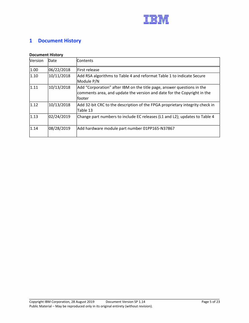
1 Document History
Document History Version Date Contents
1.00 06/22/2018 First release 1.10 10/11/2018 Add RSA algorithms to Table 4 and reformat Table 1 to indicate Secure
Module P/N 1.11 10/13/2018 Add “Corporation” after IBM on the title page, answer questions in the
comments area, and update the version and date for the Copyright in the footer
1.12 10/13/2018 Add 32-bit CRC to the description of the FPGA proprietary integrity check in Table 13
1.13 02/24/2019 Change part numbers to include EC releases (L1 and L2); updates to Table 4
1.14 08/28/2019 Add hardware module part number 01PP165-N37867

Copyright IBM Corporation, 28 August 2019 Document Version SP 1.14 Page 6 of 23 Public Material – May be reproduced only in its original entirety (without revision).
2 Introduction This document defines the Security Policy for the IBM 4768 Cryptographic Coprocessor Security Module, hereafter denoted the Module. This Module with Miniboot software resident in ROM and code flash, provides security officers, users, and the security policy governing access to those services. This policy applies to multiple members of the 4768 product family. A multi-chip embedded product, the 4768 is a cryptographic coprocessor, a general-purpose computing environment with accelerator engines, executing software and retaining secrets, despite foreseeable physical or logical attacks. End users can base high-assurance applications, such as digital signature generation or financial transaction processing, on this platform. Firmware identifiers refer to unambiguously identifiable leading characters of Segment 1 (firmware) hash, a unique value describing firmware configuration. The actual value, a cryptographic hash of the segment image, is returned by configuration queries.
Table 1 – Cryptographic Module Configurations
Module Module P/N and
Version FW Version
1 4768-001 01PP165-N36741 POST0 v0651 MB0 v0660
Segment 1 Information Name: 6.0.12z P0662 M0663 P0652 F08A8 Hash data: d608bcadec5513fda6f6a02603f241c9 dd935178b2d0774554089693f7bbcbe3 47848b07353f3c096b56bbc137d1fb54 647772e0aa547400a2f012620db5aeb7
2 4768-001 01KV353-N37513 POST0 v0651 MB0 v0650
Segment 1 Information Name: 6.0.12z P0662 M0663 P0652 F08A8 Hash data: d608bcadec5513fda6f6a02603f241c9 dd935178b2d0774554089693f7bbcbe3 47848b07353f3c096b56bbc137d1fb54 647772e0aa547400a2f012620db5aeb7

Copyright IBM Corporation, 28 August 2019 Document Version SP 1.14 Page 7 of 23 Public Material – May be reproduced only in its original entirety (without revision).
3 4768-001 01PP165-N37867 POST0 v0651 MB0 v0660
Segment 1 Information Name: 6.0.12z P0662 M0663 P0652 F08A8 Hash data: d608bcadec5513fda6f6a02603f241c9 dd935178b2d0774554089693f7bbcbe3 47848b07353f3c096b56bbc137d1fb54 647772e0aa547400a2f012620db5aeb7
The Module is intended for use by US Federal agencies and other markets that require FIPS 140-2 validated Level 4. End users can base high-assurance applications, such as digital signature generation or financial transaction processing, on this platform. Note that this policy covers services of trusted, lower layers of internal firmware (Layers 0 and 1, and a stub of Layer 2). Higher layers, OS and applications (2 and 3) are not included in the current validation. Layers 2 and 3 must not be run; otherwise, it will no longer be a FIPS module. The installation of such components is out of scope and would require a separate validation to maintain FIPS 140-2 compliance. However, the security foundations do not require a cooperative or trustworthy OS/application for consistent and secure Miniboot operation. The cryptographic boundary is the enclosure of the self-contained Module of the 4768 card. The Module is labeled unambiguously with model and part numbers of the host PCIe card, and that of the Module itself. The correspondence between end-user product, Module, and security policy is self-explanatory. The FIPS 140-2 security levels for the Module are as follows:
Table 2 – Security Level of Security Requirements
Security Requirement Security Level
Cryptographic Module Specification 4
Cryptographic Module Ports and Interfaces 4
Roles, Services, and Authentication 4
Finite State Model 4
Physical Security 4
Operational Environment N/A
Cryptographic Key Management 4
EMI/EMC 4
Self-Tests 4
Design Assurance 4
Mitigation of Other Attacks N/A
Copyright IBM Corporation, 28 August 2019 Document Version SP 1.14 Page 8 of 23 Public Material – May be reproduced only in its original entirety (without revision).
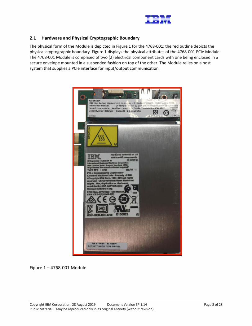
2.1 Hardware and Physical Cryptographic Boundary
The physical form of the Module is depicted in Figure 1 for the 4768-001; the red outline depicts the physical cryptographic boundary. Figure 1 displays the physical attributes of the 4768-001 PCIe Module. The 4768-001 Module is comprised of two (2) electrical component cards with one being enclosed in a secure envelope mounted in a suspended fashion on top of the other. The Module relies on a host system that supplies a PCIe interface for input/output communication.
Figure 1 – 4768-001 Module
Copyright IBM Corporation, 28 August 2019 Document Version SP 1.14 Page 9 of 23 Public Material – May be reproduced only in its original entirety (without revision).
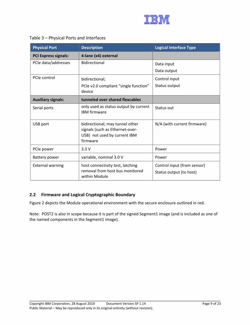
Table 3 – Physical Ports and Interfaces
Physical Port Description Logical Interface Type
PCI Express signals: 4-lane (x4) external PCIe data/addresses Bidirectional Data input
Data output PCIe control bidirectional;
PCIe v2.0 compliant “single function” device
Control input Status output
Auxiliary signals: tunneled over shared flexcables
Serial ports only used as status output by current IBM firmware
Status out
USB port bidirectional; may tunnel other signals (such as Ethernet-over-USB)not used by current IBM firmware
N/A (with current firmware)
PCIe power 3.3 V Power
Battery power variable, nominal 3.0 V Power
External warning host connectivity test, latching removal from host bus monitored within Module
Control input (from sensor) Status output (to host)
2.2 Firmware and Logical Cryptographic Boundary
Figure 2 depicts the Module operational environment with the secure enclosure outlined in red. Note: POST2 is also in scope because it is part of the signed Segment1 image (and is included as one of the named components in the Segment1 image).

Copyright IBM Corporation, 28 August 2019 Document Version SP 1.14 Page 10 of 23 Public Material – May be reproduced only in its original entirety (without revision).
Figure 2 – 4768-001 Block Diagram
Figure 3 – Module Software Architecture – Example Usage
2.3 Mode of Operation
The Module uses only approved algorithms and modes of operation. If the Module is functional, and the validated firmware variant is loaded to a validated hardware platform(s), the Module is in FIPS mode for Segments 0 and 1. The running of Seg2 and Seg3 are outside this FIPS validation. However, the loading of Seg2 and Seg3 are inside this FIPS validation. The “Signed Health Query” (Miniboot 1), in addition to

Copyright IBM Corporation, 28 August 2019 Document Version SP 1.14 Page 11 of 23 Public Material – May be reproduced only in its original entirety (without revision).
segment ownership and revision number, returns code layers’ contents’ SHA-512 hashes. Please see Table 1 - Cryptographic Module Configurations for Module Hardware Part Number and the Segment 1 hash being validated.
3 Cryptographic Functionality The Module implements the FIPS Approved and Non-Approved but Allowed cryptographic functions listed in the tables below.
Table 4 – Approved Cryptographic Functions
Algorithm Description Cert #
AES
[FIPS 197, SP 800-38A] Functions: Encryption, Decryption Modes: ECB, CBC Key sizes: 128, 192, and 256 bits NOTE: This is tested, but not used.
4815
AES/CMAC Functions: Generation and Verification NOTE: This is tested, but not used.
4815
CKG A vendor affirmed (VA) cryptographic key generator [SP800-133] is included as allowed by IG D.12.
• Asymmetric Key Generation (SP 800-133 § 6) (Note: The resulting generated seeds for asymmetric keys are unmodified output from the DRBG.)
VA
DRBG [NIST SP800-90A Rev 1] AES-256 CTR_DRBG using a derivation function and 1024 bits of entropy input
2130
ECDSA
[FIPS 186-4] Functions: Key generation and signature verification Curves/Key sizes: P-521 w/ SHA 512
1450
CVL ECDSA SigGen Component
[FIPS 186-4] Functions: Signature generation Curves/Key sizes: P-521 w/ SHA 512
1893
Copyright IBM Corporation, 28 August 2019 Document Version SP 1.14 Page 12 of 23 Public Material – May be reproduced only in its original entirety (without revision).
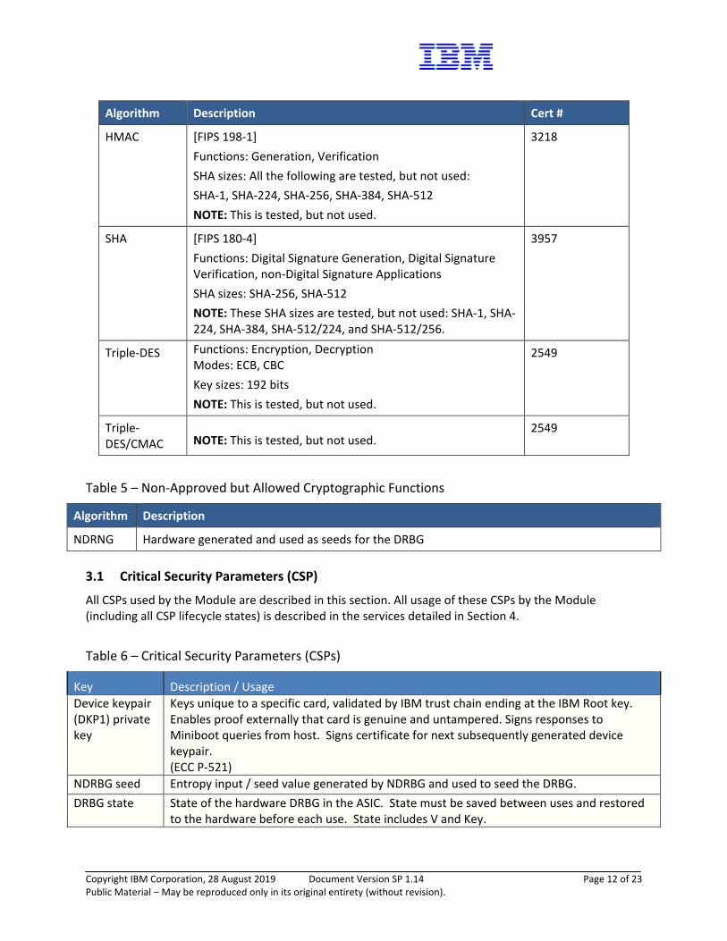
Algorithm Description Cert #
HMAC [FIPS 198-1] Functions: Generation, Verification SHA sizes: All the following are tested, but not used: SHA-1, SHA-224, SHA-256, SHA-384, SHA-512 NOTE: This is tested, but not used.
3218
SHA [FIPS 180-4] Functions: Digital Signature Generation, Digital Signature Verification, non-Digital Signature Applications SHA sizes: SHA-256, SHA-512 NOTE: These SHA sizes are tested, but not used: SHA-1, SHA-224, SHA-384, SHA-512/224, and SHA-512/256.
3957
Triple-DES Functions: Encryption, Decryption Modes: ECB, CBC Key sizes: 192 bits NOTE: This is tested, but not used.
2549
Triple-DES/CMAC
NOTE: This is tested, but not used.
2549
Table 5 – Non-Approved but Allowed Cryptographic Functions
Algorithm Description
NDRNG Hardware generated and used as seeds for the DRBG 3.1 Critical Security Parameters (CSP)
All CSPs used by the Module are described in this section. All usage of these CSPs by the Module (including all CSP lifecycle states) is described in the services detailed in Section 4.
Table 6 – Critical Security Parameters (CSPs)
Key Description / Usage Device keypair (DKP1) private key
Keys unique to a specific card, validated by IBM trust chain ending at the IBM Root key. Enables proof externally that card is genuine and untampered. Signs responses to Miniboot queries from host. Signs certificate for next subsequently generated device keypair. (ECC P-521)
NDRBG seed Entropy input / seed value generated by NDRBG and used to seed the DRBG. DRBG state State of the hardware DRBG in the ASIC. State must be saved between uses and restored
to the hardware before each use. State includes V and Key.

Copyright IBM Corporation, 28 August 2019 Document Version SP 1.14 Page 13 of 23 Public Material – May be reproduced only in its original entirety (without revision).
3.2 Public Keys
Table 7 - Public Keys
Key Description / Usage Officer1 public key Authenticates commands controlled by CO1, including new Seg1 or Seg2 firmware.
(ECC P-521) Officer2 public key Authenticates commands controlled by CO2, including new Seg3 firmware.
(ECC P-521) Officer3 public key Authenticates commands controlled by CO3.
(ECC P-521) Device keypair (DKP1) public key
Authenticate Seg1 responses. (ECC P-521)
IBM Class Root public key
Authenticate certificate for the first Device public key (DKP1 public key) to be generated. (ECC P-521)
4 Roles, Authentication and Services 4.1 Assumption of Roles
The Role descriptions are noted in the Role Description table:
Table 8 - Role Description
Role ID Role Description Authentication Type Authentication Data
CO1 and User role
Cryptographic Officer 1 - Owns Segment 1 and established by IBM as the base authority - Also User role
Identity-based Digital Signature ECC P-521
CO2 Cryptographic Officer 2 - Owns Segment 2 and established by CO1
Identity-based Digital Signature ECC P-521
CO3 Cryptographic Officer 3 - Owns Segment 3 and established by CO2
Identity-based Digital Signature ECC P-521
Copyright IBM Corporation, 28 August 2019 Document Version SP 1.14 Page 14 of 23 Public Material – May be reproduced only in its original entirety (without revision).
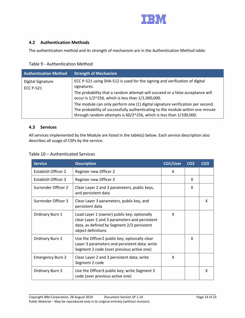
4.2 Authentication Methods
The authentication method and its strength of mechanism are in the Authentication Method table:
Table 9 - Authentication Method
Authentication Method Strength of Mechanism
Digital Signature ECC P-521
ECC P-521 using SHA-512 is used for the signing and verification of digital signatures. The probability that a random attempt will succeed or a false acceptance will occur is 1/2^256, which is less than 1/1,000,000. The module can only perform one (1) digital signature verification per second. The probability of successfully authenticating to the module within one minute through random attempts is 60/2^256, which is less than 1/100,000.
4.3 Services
All services implemented by the Module are listed in the table(s) below. Each service description also describes all usage of CSPs by the service.
Table 10 – Authenticated Services
Service Description CO1/User CO2 CO3
Establish Officer 2 Register new Officer 2 X
Establish Officer 3 Register new Officer 3 X
Surrender Officer 2 Clear Layer 2 and 3 parameters, public keys, and persistent data
X
Surrender Officer 3 Clear Layer 3 parameters, public key, and persistent data
X
Ordinary Burn 1 Load Layer 1 (owner) public key; optionally clear Layer 2 and 3 parameters and persistent data, as defined by Segment 2/3 persistent object definitions
X
Ordinary Burn 2 Use the Officer2 public key; optionally clear Layer 3 parameters and persistent data; write Segment 2 code (over previous active one)
X
Emergency Burn 2 Clear Layer 2 and 3 persistent data; write Segment 2 code
X
Ordinary Burn 3 Use the Officer3 public key; write Segment 3 code (over previous active one)
X
Copyright IBM Corporation, 28 August 2019 Document Version SP 1.14 Page 15 of 23 Public Material – May be reproduced only in its original entirety (without revision).
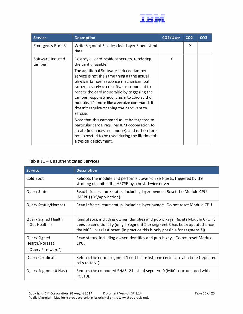
Service Description CO1/User CO2 CO3
Emergency Burn 3 Write Segment 3 code; clear Layer 3 persistent data
X
Software-induced tamper
Destroy all card-resident secrets, rendering the card unusable. The additional Software-induced tamper service is not the same thing as the actual physical tamper response mechanism, but rather, a rarely used software command to render the card inoperable by triggering the tamper response mechanism to zeroize the module. It’s more like a zeroize command. It doesn’t require opening the hardware to zeroize. Note that this command must be targeted to particular cards, requires IBM cooperation to create (instances are unique), and is therefore not expected to be used during the lifetime of a typical deployment.
X
Table 11 – Unauthenticated Services
Service Description
Cold Boot Reboots the module and performs power-on self-tests, triggered by the strobing of a bit in the HRCSR by a host device driver.
Query Status Read infrastructure status, including layer owners. Reset the Module CPU (MCPU) (OS/application).
Query Status/Noreset
Read infrastructure status, including layer owners. Do not reset Module CPU.
Query Signed Health (“Get Health”)
Read status, including owner identities and public keys. Resets Module CPU. It does so conditionally (only if segment 2 or segment 3 has been updated since the MCPU was last reset [in practice this is only possible for segment 3])
Query Signed Health/Noreset (“Query Firmware”)
Read status, including owner identities and public keys. Do not reset Module CPU.
Query Certificate Returns the entire segment 1 certificate list, one certificate at a time (repeated calls to MB1).
Query Segment 0 Hash Returns the computed SHA512 hash of segment 0 (MB0 concatenated with POST0).
Copyright IBM Corporation, 28 August 2019 Document Version SP 1.14 Page 16 of 23 Public Material – May be reproduced only in its original entirety (without revision).
Service Description
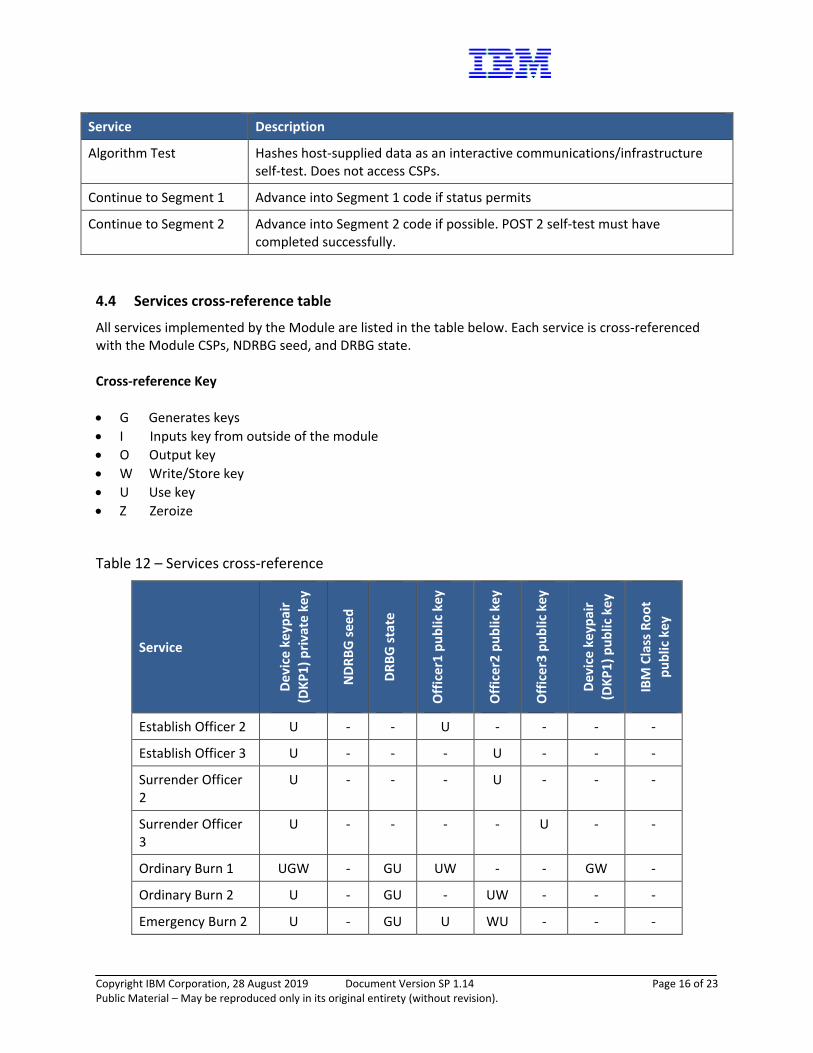
Algorithm Test Hashes host-supplied data as an interactive communications/infrastructure self-test. Does not access CSPs.
Continue to Segment 1 Advance into Segment 1 code if status permits
Continue to Segment 2 Advance into Segment 2 code if possible. POST 2 self-test must have completed successfully.
4.4 Services cross-reference table
All services implemented by the Module are listed in the table below. Each service is cross-referenced with the Module CSPs, NDRBG seed, and DRBG state. Cross-reference Key • G Generates keys • I Inputs key from outside of the module • O Output key • W Write/Store key • U Use key • Z Zeroize
Table 12 – Services cross-reference
Service
Devi
ce k
eypa
ir (D
KP1)
priv
ate
key
NDR
BG se
ed
DRBG
stat
e
Off
icer
1 pu
blic
key
Off
icer
2 pu
blic
key
Off
icer
3 pu
blic
key
Devi
ce k
eypa
ir (D
KP1)
pub
lic k
ey
IBM
Cla
ss R
oot
publ
ic k
ey
Establish Officer 2 U - - U - - - -
Establish Officer 3 U - - - U - - -
Surrender Officer 2
U - - - U - - -
Surrender Officer 3
U - - - - U - -
Ordinary Burn 1 UGW - GU UW - - GW -
Ordinary Burn 2 U - GU - UW - - -
Emergency Burn 2 U - GU U WU - - -

Copyright IBM Corporation, 28 August 2019 Document Version SP 1.14 Page 17 of 23 Public Material – May be reproduced only in its original entirety (without revision).
Service
Devi
ce k
eypa
ir (D
KP1)
priv
ate
key
NDR
BG se
ed
DRBG
stat
e
Off
icer
1 pu
blic
key
Off
icer
2 pu
blic
key
Off
icer
3 pu
blic
key
Devi
ce k
eypa
ir (D
KP1)
pub
lic k
ey
IBM
Cla
ss R
oot
publ
ic k
ey
Ordinary Burn 3 U - GU - - UW - -
Emergency Burn 3 U - GU - U WU - -
Software-induced tamper
Z Z Z U - - - -
Cold Boot - GU G - - - - -
Query Status - - - - - - - -
Query Status/Noreset
- - - - - - - -
Query Signed Health (“Get Health”)
U - - O O O - -
Query Signed Health/Noreset (“Query Firmware”)
U - - O O O - -
Query Certificate U - GU - - - O O
Query Segment 0 Hash
- - - - - - - -
Algorithm Test - GU GU - - - - -
Continue to Segment 1
- - - - - - - -
Continue to Segment 2
- - - - - - - -
5 Self-tests Each time the Module is powered on, it tests that the cryptographic algorithms still operate correctly and that sensitive data have not been damaged. Power on self–tests are available on demand by power cycling the Module.
Copyright IBM Corporation, 28 August 2019 Document Version SP 1.14 Page 18 of 23 Public Material – May be reproduced only in its original entirety (without revision).
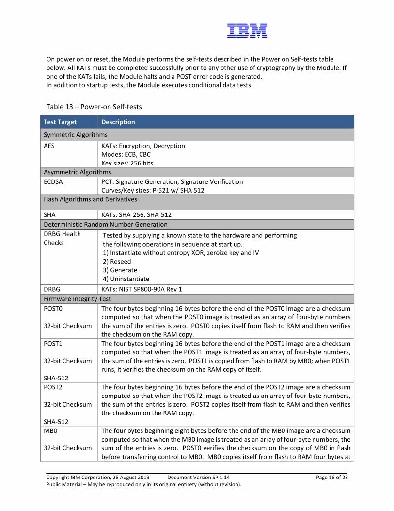
On power on or reset, the Module performs the self-tests described in the Power on Self-tests table below. All KATs must be completed successfully prior to any other use of cryptography by the Module. If one of the KATs fails, the Module halts and a POST error code is generated. In addition to startup tests, the Module executes conditional data tests.
Table 13 – Power-on Self-tests
Test Target Description
Symmetric Algorithms AES
KATs: Encryption, Decryption Modes: ECB, CBC Key sizes: 256 bits
Asymmetric Algorithms ECDSA
PCT: Signature Generation, Signature Verification Curves/Key sizes: P-521 w/ SHA 512
Hash Algorithms and Derivatives
SHA KATs: SHA-256, SHA-512 Deterministic Random Number Generation DRBG Health Checks
Tested by supplying a known state to the hardware and performing the following operations in sequence at start up. 1) Instantiate without entropy XOR, zeroize key and IV 2) Reseed 3) Generate 4) Uninstantiate
DRBG KATs: NIST SP800-90A Rev 1 Firmware Integrity Test POST0 32-bit Checksum
The four bytes beginning 16 bytes before the end of the POST0 image are a checksum computed so that when the POST0 image is treated as an array of four-byte numbers the sum of the entries is zero. POST0 copies itself from flash to RAM and then verifies the checksum on the RAM copy.
POST1 32-bit Checksum SHA-512
The four bytes beginning 16 bytes before the end of the POST1 image are a checksum computed so that when the POST1 image is treated as an array of four-byte numbers, the sum of the entries is zero. POST1 is copied from flash to RAM by MB0; when POST1 runs, it verifies the checksum on the RAM copy of itself.
POST2 32-bit Checksum SHA-512
The four bytes beginning 16 bytes before the end of the POST2 image are a checksum computed so that when the POST2 image is treated as an array of four-byte numbers, the sum of the entries is zero. POST2 copies itself from flash to RAM and then verifies the checksum on the RAM copy.
MB0 32-bit Checksum
The four bytes beginning eight bytes before the end of the MB0 image are a checksum computed so that when the MB0 image is treated as an array of four-byte numbers, the sum of the entries is zero. POST0 verifies the checksum on the copy of MB0 in flash before transferring control to MB0. MB0 copies itself from flash to RAM four bytes at
Copyright IBM Corporation, 28 August 2019 Document Version SP 1.14 Page 19 of 23 Public Material – May be reproduced only in its original entirety (without revision).
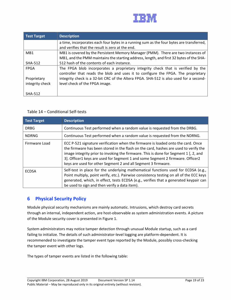
Test Target Description a time, incorporates each four bytes in a running sum as the four bytes are transferred, and verifies that the result is zero at the end.
MB1 SHA-512
MB1 is covered by the Persistent Memory Manager (PMM). There are two instances of MB1, and the PMM maintains the starting address, length, and first 32 bytes of the SHA-512 hash of the contents of each instance.
FPGA Proprietary integrity check SHA-512
The FPGA blob incorporates a proprietary integrity check that is verified by the controller that reads the blob and uses it to configure the FPGA. The proprietary integrity check is a 32-bit CRC of the Altera FPGA. SHA-512 is also used for a second-level check of the FPGA image.
Table 14 – Conditional Self-tests
Test Target Description
DRBG Continuous Test performed when a random value is requested from the DRBG.
NDRNG Continuous Test performed when a random value is requested from the NDRNG.
Firmware Load ECC P-521 signature verification when the firmware is loaded onto the card. Once the firmware has been stored in the flash on the card, hashes are used to verify the image integrity prior to invoking the firmware. This is done for Segment 1 [, 2, and 3]. Officer1 keys are used for Segment 1 and some Segment 2 firmware. Officer2 keys are used for other Segment 2 and all Segment 3 firmware.
ECDSA Self-test in place for the underlying mathematical functions used for ECDSA (e.g., Point multiply, point verify, etc.). Pairwise consistency testing on all of the ECC keys generated, which, in effect, tests ECDSA (e.g., verifies that a generated keypair can be used to sign and then verify a data item).
6 Physical Security Policy Module physical security mechanisms are mainly automatic. Intrusions, which destroy card secrets through an internal, independent action, are host-observable as system administration events. A picture of the Module security cover is presented in Figure 1.
System administrators may notice tamper detection through unusual Module startup, such as a card failing to initialize. The details of such administrator-level logging are platform-dependent. It is recommended to investigate the tamper event type reported by the Module, possibly cross-checking the tamper event with other logs.
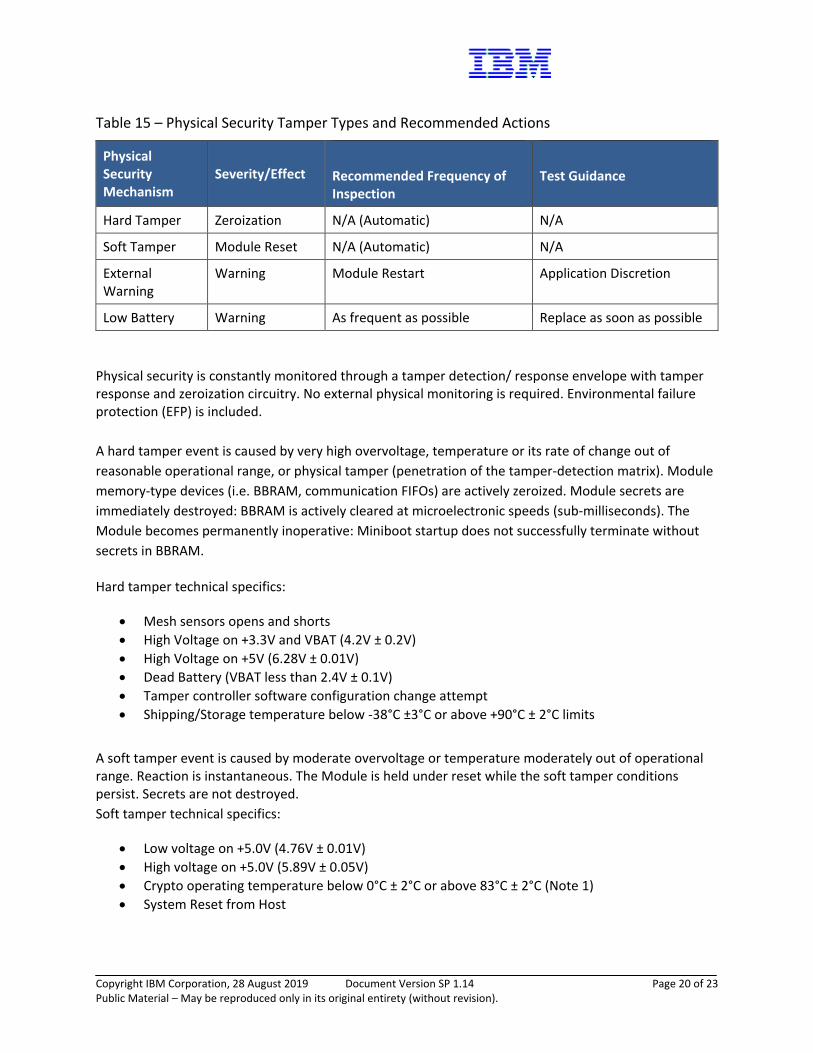
The types of tamper events are listed in the following table:
Copyright IBM Corporation, 28 August 2019 Document Version SP 1.14 Page 20 of 23 Public Material – May be reproduced only in its original entirety (without revision).
Table 15 – Physical Security Tamper Types and Recommended Actions
Physical Security Mechanism
Severity/Effect Recommended Frequency of Inspection
Test Guidance
Hard Tamper Zeroization N/A (Automatic) N/A
Soft Tamper Module Reset N/A (Automatic) N/A
External Warning
Warning Module Restart Application Discretion
Low Battery Warning As frequent as possible Replace as soon as possible Physical security is constantly monitored through a tamper detection/ response envelope with tamper response and zeroization circuitry. No external physical monitoring is required. Environmental failure protection (EFP) is included. A hard tamper event is caused by very high overvoltage, temperature or its rate of change out of reasonable operational range, or physical tamper (penetration of the tamper-detection matrix). Module memory-type devices (i.e. BBRAM, communication FIFOs) are actively zeroized. Module secrets are immediately destroyed: BBRAM is actively cleared at microelectronic speeds (sub-milliseconds). The Module becomes permanently inoperative: Miniboot startup does not successfully terminate without secrets in BBRAM.
Hard tamper technical specifics:
• Mesh sensors opens and shorts • High Voltage on +3.3V and VBAT (4.2V ± 0.2V) • High Voltage on +5V (6.28V ± 0.01V) • Dead Battery (VBAT less than 2.4V ± 0.1V) • Tamper controller software configuration change attempt • Shipping/Storage temperature below -38°C ±3°C or above +90°C ± 2°C limits
A soft tamper event is caused by moderate overvoltage or temperature moderately out of operational range. Reaction is instantaneous. The Module is held under reset while the soft tamper conditions persist. Secrets are not destroyed. Soft tamper technical specifics:
• Low voltage on +5.0V (4.76V ± 0.01V) • High voltage on +5.0V (5.89V ± 0.05V) • Crypto operating temperature below 0°C ± 2°C or above 83°C ± 2°C (Note 1) • System Reset from Host

Copyright IBM Corporation, 28 August 2019 Document Version SP 1.14 Page 21 of 23 Public Material – May be reproduced only in its original entirety (without revision).
7 Operational Environment The Module is designated as a limited operational environment under the FIPS 140-2 definitions. The Module includes a firmware load service to support necessary updates. New firmware versions within the scope of this validation must be validated through the FIPS 140-2 CMVP. Any other firmware loaded into this Module is out of the scope of this validation and require a separate FIPS 140-2 validation.
8 Mitigation of Other Attacks Policy N/A
9 Security Rules and Guidance The Module design corresponds to the Module security rules. This section documents the security rules enforced by the cryptographic Module to implement the security requirements of this FIPS 140-2 Level 4 Module. 1. The Module will provide four distinct operator roles: User and Cryptographic Officer 1, Cryptographic
Officer 2, and Cryptographic Officer 3.
2. The Module will provide identity-based authentication.
3. The Module will clear previous authentications on power cycle. This is accomplished by clearing RAM and all running applications.
4. When the Module has not been placed in a valid role, the operator will not have access to any cryptographic services.
5. The operator will be capable of commanding the Module to perform the power on self-tests by cycling power or resetting the Module.
6. Power on self-tests do not require any operator action.
7. Data output will be inhibited during key generation, self-tests, zeroization, and error states. This is accomplished by the Custom Communication Hardware in the PCIe interface path.
8. Status information does not contain CSPs or sensitive data that if misused could lead to a compromise of the Module.
9. There are no restrictions on which keys or CSPs are zeroized by the zeroization service.
10. The Module does not support concurrent operators.
11. The Module does not support a maintenance interface or role.
12. The Module does not support manual key entry.
13. The Module does not have any external input/output devices used for entry/output of data.
14. The Module does not enter or output plaintext CSPs.
15. The Module does not output intermediate key values.

Copyright IBM Corporation, 28 August 2019 Document Version SP 1.14 Page 22 of 23 Public Material – May be reproduced only in its original entirety (without revision).
10 References and Definitions The following are references for this Security Policy.
Table 16 – References
Abbreviation Full Specification Name
FIPS140-2 Security Requirements for Cryptographic Modules, May 25, 2001
SP800-90A Rev 1 Recommendation for Random Number Generation Using Deterministic Random Bit Generators, June 2015
Annex A Approved Security Functions for FIPS PUB 140-2, Security Requirements for Cryptographic Modules
Annex B Approved Protection Profiles for FIPS PUB 140-2, Security Requirements for Cryptographic Modules
Annex C Approved Random Number Generators for FIPS PUB 140-2, Security Requirements for Cryptographic Modules
Annex D Approved Key Establishment Techniques for FIPS PUB 140-2, Security Requirements for Cryptographic Modules
Table 17 – Acronyms and Definitions
Acronym Definition
CA Certificate Authority
CCP Card Configuration Parameters
BBRAM Battery-Backed static RAM
CSP Critical Security Parameters
EDC Error Detection code
Device Keypair Device-specific public-key keypair generated and retained by Segment 1. It is non-exportable, traceable back to the IBM factory CA through a certificate chain, and may be used by external parties to verify the identity of a Module, through outbound authentication (OA).
Firmware identifier
An unambiguous status identifier (“Segment 1 hash”), used to quickly summarize firmware contents. It is the SHA-256 hash of firmware contents, possibly including hardware, such as an FPGA bitfile. Segments are identified by their own segment hashes, but this document only specifies Segment 1. Modules loaded with validated Segment 2 and 3 must specify their specific validated configurations.
FWID Abbreviation of Firmware identifier

Copyright IBM Corporation, 28 August 2019 Document Version SP 1.14 Page 23 of 23 Public Material – May be reproduced only in its original entirety (without revision).
Acronym Definition
HLM Hardware Lock Microcontroller, a dedicated microcontroller which assisted previous 47xx generations with access control and management of persistent storage. While current generations no longer contain an actual HLM controller, some of the relevant functionality has been retained. Documentation refers to these features as “HLM (infrastructure)” for historical reasons.
HSEB High-speed erase BBRAM, a dedicated BBRAM chip actively erased upon tamper. The most valuable Miniboot secrets reside within this region, which is wiped within milliseconds of detecting a tamper event.
IA Inbound Authentication, Miniboot authenticates each command request individually.
KAT Known Answer Test
MCPU The Module CPU (MCPU) is a redundant embedded PowerPC 476. It is not used in the FIPS mode of operation.
Miniboot Software component of Module firmware. Miniboot functionality, together with POST, roughly corresponds to those of a system BIOS in PCs, with obvious additions to cover cryptographic functionality, Module-specific hardware, and act as the Module security controller.
OA Outbound Authentication, infrastructure capable of signing by a card-resident, non-exportable private key. External parties, including other Modules, can verify that signed content has been generated by an untampered Module firmware (Segment 1). An extension allows OA to manage private keys for OS or applications (Segment 2 or 3).
PCIe PCI Express, the external interface of our Module (also abbreviated as PCI-E).
PN Part Number
POST Power-On Self-Test, infrastructure tests resident in ROM and flash.
RAS Abbreviation of Reliability, Availability, Serviceability
SSP Security Service Processor (SSP), a dedicated processor executing Miniboot and most of POST (i.e., all privileged code). The SSP is an embedded PowerPC 405.
Segment 1F Segment 1F is the rewritable part of card infrastructure, including the FPGA programming file, and POST 2, all protected as part of Segment 1. Used only when the FPGA bitfile is explicitly mentioned in Segment 1 operations.