IBM BladeCenter JS21 Technical Overview and Introduction · viii IBM BladeCenter JS21 Technical...
62
ibm.com/redbooks Redpaper IBM Front cover IBM BladeCenter JS21 Technical Overview and Introduction Trina Bunting Wayne Kimble High-performance blade server ideal for extremely dense HPC clusters First IBM blade server with built-in virtualization for server consolidation Exceptional SIMD acceleration for life/earth scientific research and high-performance engineering
Transcript of IBM BladeCenter JS21 Technical Overview and Introduction · viii IBM BladeCenter JS21 Technical...

ibm.com/redbooks Redpaper
IBM Front cover
IBM BladeCenter JS21 Technical Overview and Introduction
Trina BuntingWayne Kimble
High-performance blade server ideal for extremely dense HPC clusters
First IBM blade server with built-in virtualization for server consolidation
Exceptional SIMD acceleration for life/earth scientific research and high-performance engineering


International Technical Support Organization
IBM BladeCenter JS21 Technical Overview and Introduction
March 2006

© Copyright International Business Machines Corporation 2006. All rights reserved.Note to U.S. Government Users Restricted Rights -- Use, duplication or disclosure restricted by GSA ADP ScheduleContract with IBM Corp.
First Edition (March 2006)
This edition applies to IBM® BladeCenter® JS21 Type 8844 blade server and IBM AIX 5L Version 5.2, 5.3, product number 5765-G03.
Note: Before using this information and the product it supports, read the information in “Notices” on page v.

Contents
Notices . . . . . . . . . . . . . . . . . . . . . . . . . . . . . . . . . . . . . . . . . . . . . . . . . . . . . . . . . . . . . . . . . .vTrademarks . . . . . . . . . . . . . . . . . . . . . . . . . . . . . . . . . . . . . . . . . . . . . . . . . . . . . . . . . . . . . . vi
Preface . . . . . . . . . . . . . . . . . . . . . . . . . . . . . . . . . . . . . . . . . . . . . . . . . . . . . . . . . . . . . . . . . viiThe team that wrote this Redpaper . . . . . . . . . . . . . . . . . . . . . . . . . . . . . . . . . . . . . . . . . . . . viiBecome a published author . . . . . . . . . . . . . . . . . . . . . . . . . . . . . . . . . . . . . . . . . . . . . . . . . viiiComments welcome. . . . . . . . . . . . . . . . . . . . . . . . . . . . . . . . . . . . . . . . . . . . . . . . . . . . . . . viii
Chapter 1. General Description . . . . . . . . . . . . . . . . . . . . . . . . . . . . . . . . . . . . . . . . . . . . . 11.1 System specifications . . . . . . . . . . . . . . . . . . . . . . . . . . . . . . . . . . . . . . . . . . . . . . . . . . . 31.2 Physical specifications . . . . . . . . . . . . . . . . . . . . . . . . . . . . . . . . . . . . . . . . . . . . . . . . . . 31.3 Physical packaging . . . . . . . . . . . . . . . . . . . . . . . . . . . . . . . . . . . . . . . . . . . . . . . . . . . . . 31.4 BladeCenter JS21 models . . . . . . . . . . . . . . . . . . . . . . . . . . . . . . . . . . . . . . . . . . . . . . . 41.5 Minimum and optional features . . . . . . . . . . . . . . . . . . . . . . . . . . . . . . . . . . . . . . . . . . . . 51.6 Processor features . . . . . . . . . . . . . . . . . . . . . . . . . . . . . . . . . . . . . . . . . . . . . . . . . . . . . 61.7 Memory features . . . . . . . . . . . . . . . . . . . . . . . . . . . . . . . . . . . . . . . . . . . . . . . . . . . . . . . 7
1.7.1 Memory DIMMs. . . . . . . . . . . . . . . . . . . . . . . . . . . . . . . . . . . . . . . . . . . . . . . . . . . . 71.8 Internal Serial Attached SCSI (SAS) Disk . . . . . . . . . . . . . . . . . . . . . . . . . . . . . . . . . . . . 7
1.8.1 Hard Disk Drives . . . . . . . . . . . . . . . . . . . . . . . . . . . . . . . . . . . . . . . . . . . . . . . . . . . 81.9 BladeCenter chassis . . . . . . . . . . . . . . . . . . . . . . . . . . . . . . . . . . . . . . . . . . . . . . . . . . . . 8
1.9.1 BladeCenter Power Modules . . . . . . . . . . . . . . . . . . . . . . . . . . . . . . . . . . . . . . . . 121.9.2 BladeCenter Management Modules . . . . . . . . . . . . . . . . . . . . . . . . . . . . . . . . . . . 121.9.3 Media features . . . . . . . . . . . . . . . . . . . . . . . . . . . . . . . . . . . . . . . . . . . . . . . . . . . 12
1.10 Serial over local area network (LAN) . . . . . . . . . . . . . . . . . . . . . . . . . . . . . . . . . . . . . 131.11 Statement of direction . . . . . . . . . . . . . . . . . . . . . . . . . . . . . . . . . . . . . . . . . . . . . . . . . 13
Chapter 2. Architecture and technical overview . . . . . . . . . . . . . . . . . . . . . . . . . . . . . . 152.1 PowerPC 970MP Processor . . . . . . . . . . . . . . . . . . . . . . . . . . . . . . . . . . . . . . . . . . . . . 17
2.1.1 NorthBridge. . . . . . . . . . . . . . . . . . . . . . . . . . . . . . . . . . . . . . . . . . . . . . . . . . . . . . 172.1.2 HyperTransport tunnel . . . . . . . . . . . . . . . . . . . . . . . . . . . . . . . . . . . . . . . . . . . . . 18
2.2 Cache Structure . . . . . . . . . . . . . . . . . . . . . . . . . . . . . . . . . . . . . . . . . . . . . . . . . . . . . . 192.3 Memory subsystem . . . . . . . . . . . . . . . . . . . . . . . . . . . . . . . . . . . . . . . . . . . . . . . . . . . . 19
2.3.1 Memory placement rules. . . . . . . . . . . . . . . . . . . . . . . . . . . . . . . . . . . . . . . . . . . . 192.3.2 Memory restriction. . . . . . . . . . . . . . . . . . . . . . . . . . . . . . . . . . . . . . . . . . . . . . . . . 202.3.3 Memory throughput . . . . . . . . . . . . . . . . . . . . . . . . . . . . . . . . . . . . . . . . . . . . . . . . 20
2.4 I/O subsystem . . . . . . . . . . . . . . . . . . . . . . . . . . . . . . . . . . . . . . . . . . . . . . . . . . . . . . . . 202.4.1 PCI-Express . . . . . . . . . . . . . . . . . . . . . . . . . . . . . . . . . . . . . . . . . . . . . . . . . . . . . 21
2.5 Universal Serial Bus (USB) Subsystem . . . . . . . . . . . . . . . . . . . . . . . . . . . . . . . . . . . . 212.6 Mass Storage . . . . . . . . . . . . . . . . . . . . . . . . . . . . . . . . . . . . . . . . . . . . . . . . . . . . . . . . 212.7 Storage . . . . . . . . . . . . . . . . . . . . . . . . . . . . . . . . . . . . . . . . . . . . . . . . . . . . . . . . . . . . . 21
2.7.1 Serial Attached SCSI (SAS) storage subsystem. . . . . . . . . . . . . . . . . . . . . . . . . . 222.8 Expansion cards . . . . . . . . . . . . . . . . . . . . . . . . . . . . . . . . . . . . . . . . . . . . . . . . . . . . . . 222.9 Supported I/O Modules . . . . . . . . . . . . . . . . . . . . . . . . . . . . . . . . . . . . . . . . . . . . . . . . . 232.10 Advanced Power Management . . . . . . . . . . . . . . . . . . . . . . . . . . . . . . . . . . . . . . . . . . 25
2.10.1 Power Oversubscription in the BladeCenter environment . . . . . . . . . . . . . . . . . 252.11 Trusted Platform Module. . . . . . . . . . . . . . . . . . . . . . . . . . . . . . . . . . . . . . . . . . . . . . . 262.12 Logical partitioning and virtualization . . . . . . . . . . . . . . . . . . . . . . . . . . . . . . . . . . . . . 26
2.12.1 Dynamic logical partitioning . . . . . . . . . . . . . . . . . . . . . . . . . . . . . . . . . . . . . . . . 272.12.2 Virtualization . . . . . . . . . . . . . . . . . . . . . . . . . . . . . . . . . . . . . . . . . . . . . . . . . . . . 27
© Copyright IBM Corp. 2006. All rights reserved. iii

2.12.3 Advanced POWER Virtualization . . . . . . . . . . . . . . . . . . . . . . . . . . . . . . . . . . . . 282.13 Operating system support . . . . . . . . . . . . . . . . . . . . . . . . . . . . . . . . . . . . . . . . . . . . . . 32
2.13.1 AIX 5L . . . . . . . . . . . . . . . . . . . . . . . . . . . . . . . . . . . . . . . . . . . . . . . . . . . . . . . . . 322.13.2 Linux . . . . . . . . . . . . . . . . . . . . . . . . . . . . . . . . . . . . . . . . . . . . . . . . . . . . . . . . . . 33
2.14 Systems Management . . . . . . . . . . . . . . . . . . . . . . . . . . . . . . . . . . . . . . . . . . . . . . . . 332.14.1 BladeCenter Web Interface. . . . . . . . . . . . . . . . . . . . . . . . . . . . . . . . . . . . . . . . . 332.14.2 IBM Director . . . . . . . . . . . . . . . . . . . . . . . . . . . . . . . . . . . . . . . . . . . . . . . . . . . . 342.14.3 Cluster Systems Management . . . . . . . . . . . . . . . . . . . . . . . . . . . . . . . . . . . . . . 34
Chapter 3. Reliability, availability, and serviceability. . . . . . . . . . . . . . . . . . . . . . . . . . . 353.1 Reliability, fault tolerance, and data integrity. . . . . . . . . . . . . . . . . . . . . . . . . . . . . . . . . 36
3.1.1 Hardware Error Handling . . . . . . . . . . . . . . . . . . . . . . . . . . . . . . . . . . . . . . . . . . . 363.1.2 Boot Time Diagnostics . . . . . . . . . . . . . . . . . . . . . . . . . . . . . . . . . . . . . . . . . . . . . 373.1.3 Standalone Diagnostics . . . . . . . . . . . . . . . . . . . . . . . . . . . . . . . . . . . . . . . . . . . . 373.1.4 Runtime Diagnostics . . . . . . . . . . . . . . . . . . . . . . . . . . . . . . . . . . . . . . . . . . . . . . . 373.1.5 I/O Diagnostics . . . . . . . . . . . . . . . . . . . . . . . . . . . . . . . . . . . . . . . . . . . . . . . . . . . 383.1.6 Machine Check Handling and Dump Support . . . . . . . . . . . . . . . . . . . . . . . . . . . . 38
3.2 Serviceability . . . . . . . . . . . . . . . . . . . . . . . . . . . . . . . . . . . . . . . . . . . . . . . . . . . . . . . . . 393.2.1 Hardware Maintenance Manual (HMM) . . . . . . . . . . . . . . . . . . . . . . . . . . . . . . . . 393.2.2 Light Path Diagnostics . . . . . . . . . . . . . . . . . . . . . . . . . . . . . . . . . . . . . . . . . . . . . 393.2.3 Progress Codes and Error Codes. . . . . . . . . . . . . . . . . . . . . . . . . . . . . . . . . . . . . 393.2.4 FRU identification and replacement . . . . . . . . . . . . . . . . . . . . . . . . . . . . . . . . . . . 403.2.5 Call Home Support . . . . . . . . . . . . . . . . . . . . . . . . . . . . . . . . . . . . . . . . . . . . . . . . 403.2.6 Service Documentation. . . . . . . . . . . . . . . . . . . . . . . . . . . . . . . . . . . . . . . . . . . . . 403.2.7 Support Structure . . . . . . . . . . . . . . . . . . . . . . . . . . . . . . . . . . . . . . . . . . . . . . . . . 41
Appendix A. Servicing an BladeCenter JS21 . . . . . . . . . . . . . . . . . . . . . . . . . . . . . . . . . 43Resource Link . . . . . . . . . . . . . . . . . . . . . . . . . . . . . . . . . . . . . . . . . . . . . . . . . . . . . . . . . . . 44IBM Systems Hardware Information Center. . . . . . . . . . . . . . . . . . . . . . . . . . . . . . . . . . . . . 44
Abbreviations and acronyms . . . . . . . . . . . . . . . . . . . . . . . . . . . . . . . . . . . . . . . . . . . . . . 45
Related publications . . . . . . . . . . . . . . . . . . . . . . . . . . . . . . . . . . . . . . . . . . . . . . . . . . . . . 47IBM Redbooks . . . . . . . . . . . . . . . . . . . . . . . . . . . . . . . . . . . . . . . . . . . . . . . . . . . . . . . . . . . 47Other publications . . . . . . . . . . . . . . . . . . . . . . . . . . . . . . . . . . . . . . . . . . . . . . . . . . . . . . . . 47Online resources . . . . . . . . . . . . . . . . . . . . . . . . . . . . . . . . . . . . . . . . . . . . . . . . . . . . . . . . . 47How to get IBM Redbooks . . . . . . . . . . . . . . . . . . . . . . . . . . . . . . . . . . . . . . . . . . . . . . . . . . 49Help from IBM . . . . . . . . . . . . . . . . . . . . . . . . . . . . . . . . . . . . . . . . . . . . . . . . . . . . . . . . . . . 49
iv IBM BladeCenter JS21 Technical Overview and Introduction

Notices
This information was developed for products and services offered in the U.S.A.
IBM may not offer the products, services, or features discussed in this document in other countries. Consult your local IBM representative for information on the products and services currently available in your area. Any reference to an IBM product, program, or service is not intended to state or imply that only that IBM product, program, or service may be used. Any functionally equivalent product, program, or service that does not infringe any IBM intellectual property right may be used instead. However, it is the user's responsibility to evaluate and verify the operation of any non-IBM product, program, or service.
IBM may have patents or pending patent applications covering subject matter described in this document. The furnishing of this document does not give you any license to these patents. You can send license inquiries, in writing, to: IBM Director of Licensing, IBM Corporation, North Castle Drive Armonk, NY 10504-1785 U.S.A.
The following paragraph does not apply to the United Kingdom or any other country where such provisions are inconsistent with local law: INTERNATIONAL BUSINESS MACHINES CORPORATION PROVIDES THIS PUBLICATION "AS IS" WITHOUT WARRANTY OF ANY KIND, EITHER EXPRESS OR IMPLIED, INCLUDING, BUT NOT LIMITED TO, THE IMPLIED WARRANTIES OF NON-INFRINGEMENT, MERCHANTABILITY OR FITNESS FOR A PARTICULAR PURPOSE. Some states do not allow disclaimer of express or implied warranties in certain transactions, therefore, this statement may not apply to you.
This information could include technical inaccuracies or typographical errors. Changes are periodically made to the information herein; these changes will be incorporated in new editions of the publication. IBM may make improvements and changes in the product(s) and the program(s) described in this publication at any time without notice.
Any references in this information to non-IBM Web sites are provided for convenience only and do not in any manner serve as an endorsement of those Web sites. The materials at those Web sites are not part of the materials for this IBM product and use of those Web sites is at your own risk.
IBM may use or distribute any of the information you supply in any way it believes appropriate without incurring any obligation to you.
Information concerning non-IBM products was obtained from the suppliers of those products, their published announcements or other publicly available sources. IBM has not tested those products and cannot confirm the accuracy of performance, compatibility or any other claims related to non-IBM products. Questions on the capabilities of non-IBM products should be addressed to the suppliers of those products.
This information contains examples of data and reports used in daily business operations. To illustrate them as completely as possible, the examples include the names of individuals, companies, brands, and products. All of these names are fictitious and any similarity to the names and addresses used by an actual business enterprise is entirely coincidental.
COPYRIGHT LICENSE: This information contains sample application programs in source language, which illustrates programming techniques on various operating platforms. You may copy, modify, and distribute these sample programs in any form without payment to IBM, for the purposes of developing, using, marketing or distributing application programs conforming to the application programming interface for the operating platform for which the sample programs are written. These examples have not been thoroughly tested under all conditions. IBM, therefore, cannot guarantee or imply reliability, serviceability, or function of these programs. You may copy, modify, and distribute these sample programs in any form without payment to IBM for the purposes of developing, using, marketing, or distributing application programs conforming to IBM's application programming interfaces.
© Copyright IBM Corp. 2006. All rights reserved. v

TrademarksThe following terms are trademarks of the International Business Machines Corporation in the United States, other countries, or both:
AIX 5L™AIX®BladeCenter®Chipkill™Eserver®Eserver®eServer™IBM®
Micro-Partitioning™Power Architecture™Power PC®PowerPC®POWER™POWER5™pSeries®Redbooks™
Redbooks (logo) ™Resource Link™ServerProven®Virtualization Engine™WebSphere®xSeries®
The following terms are trademarks of other companies:
AltiVec is a trademark of Freescale Semiconductor, Inc.
Power Management, and all Java-based trademarks are trademarks of Sun Microsystems, Inc. in the United States, other countries, or both.
Intel, Intel logo, Intel Inside logo, and Intel Centrino logo are trademarks or registered trademarks of Intel Corporation or its subsidiaries in the United States, other countries, or both.
UNIX is a registered trademark of The Open Group in the United States and other countries.
Linux is a trademark of Linus Torvalds in the United States, other countries, or both.
Other company, product, or service names may be trademarks or service marks of others.
vi IBM BladeCenter JS21 Technical Overview and Introduction

Preface
This IBM® Redpaper presents a thorough overview of the IBM® BladeCenter® JS21 Type 8844 blade server supporting the IBM AIX® 5L™ and Linux® operating systems.
Professionals wanting to acquire a better understanding of the IBM BladeCenter® JS21 blade server and its prominent functionality should consider reading this document. The intended audience includes the following:
� Clients
� Sales and marketing professionals
� Technical support professionals
� IBM Business Partners
� Independent software vendors
This document expands the current set of BladeCenter JS21 documentation by providing a desktop reference that offers a detailed technical description of the BladeCenter JS21.
This publication does not replace the latest BladeCenter JS21 marketing materials, tools, or product documentation. It is intended as an additional source of information that, together with existing sources, you can use to enhance your knowledge of IBM BladeCenter solutions. You can view additional information at:
http://www.ibm.com/systems/bladecenter/js21/index.html
The team that wrote this RedpaperThis Redpaper was produced by a team of specialists from around the world working at the International Technical Support Organization, Austin Center.
Trina Bunting is a member of the pSeries® Advanced Technical Support Group in Dallas, Texas. She is the skills leader for AIX 5L on POWER™ blades and IBM Director. She is also the POWER blades Regional Designated Specialist skills leader for North America. She joined IBM in 1996 and was part of Technical Services and AIX 5L Support Line before joining the Advanced Technical Support Group.
Wayne Kimble is a Field Technical Sales Specialist based in Los Angeles, California, USA. He has worked with computer systems for over 25 years and has performed pre-sales technical support for the past 6 years. He is the Regional Designated Specialist for BladeCenter in the Western Region. His areas of expertise include high-performance computing and Linux on POWER.
The project that created this publication was managed by:Stephen Hochstetler
Thanks to the following people for their contributions to this project:
Arzu Gucer, Scott VetterInternational Technical Support Organization, Austin Center
© Copyright IBM Corp. 2006. All rights reserved. vii

Rufus CredleInternational Technical Support Organization, Raleigh Center
Kaena Freitas, Alan Slaughter, Willie Cole, Mark Hack, James Huston, Mark Smolen, Brian J King, Richard Lary, Larry Amy, Donn BullockIBM US
Rudolf LandIBM Germany
Michal WawrzynskiIBM Poland
Yan ZhangIBM China
Become a published authorJoin us for a two- to six-week residency program! Help write an IBM Redbook dealing with specific products or solutions, while getting hands-on experience with leading-edge technologies. You will team with IBM technical professionals, Business Partners and clients.
Your efforts will help increase product acceptance and customer satisfaction. As a bonus, you will develop a network of contacts in IBM development labs, and increase your productivity and marketability.
Find out more about the residency program, browse the residency index, and apply online at:
ibm.com/redbooks/residencies.html
Comments welcomeYour comments are important to us!
We want our papers to be as helpful as possible. Send us your comments about this Redpaper or other Redbooks™ in one of the following ways:
� Use the online Contact us review redbook form found at:
ibm.com/redbooks
� Send your comments in an email to:
� Mail your comments to:
IBM Corporation, International Technical Support OrganizationDept. JN9B Building 90511501 Burnet RoadAustin, Texas 78758-3493
viii IBM BladeCenter JS21 Technical Overview and Introduction

Chapter 1. General Description
The IBM BladeCenter JS21 Type 8844 blade server offers significant improvements in performance and reliability over the previous generation JS20 blade server delivering up to three times better performance by using the following:
� The faster IBM PowerPC® 970MP dual-core processors
� Faster, more reliable double data rate 2 (DDR2) memory options
� Serial Attached SCSI (SAS) hard disk drives
� IBM’s first blade server optimized for BladeCenter H
With built-in support for Advanced Performance Optimization with Enhanced RISC (POWER) Virtualization, the BladeCenter JS21 offers an ideal blade server solution for High-Performance Computing (HPC), AIX 5L, and server consolidation.
The BladeCenter JS21 supports a maximum of 16 GB 400 MHz error-checking and correction (ECC) Chipkill™ DDR2 memory or 8 GB 533 MHz ECC Chipkill DDR2 memory. See 1.11, “Statement of direction” on page 13 concerning support of 16 GB 533 MHz ECC Chipkill DDR2 memory. Model 31X, with 1 GB memory standard, offers two single active core, 64-bit PowerPC 970MP processors. The 51X, with 2 GB memory standard, offers two dual-core, 64-bit PowerPC 970MP processors. Each processor core includes 32/64 KB L1 (Data/Instruction) and 1 MB (non-shared) L2 cache. Processor clock rates vary based on the model of BladeCenter chassis that the BladeCenter JS21 is inserted into. For processor speed details see Table 1-7 on page 8.
Designed with the demands of enterprise and scientific computing in mind, the BladeCenter JS21 is a highly differentiated solution for high-performance Linux clusters, seismic analysis for oil and gas, UNIX® applications for retail and finance, Web serving such as with IBM WebSphere®, grid solutions, and any other custom or commercial application able to exploit the performance acceleration of AltiVec technology for data intensive workloads. The BladeCenter JS21 represents a convergence of leadership technologies and is therefore a critical component of IBM’s BladeCenter and System p server portfolio. The BladeCenter JS21 allows customers the ability to leverage the value proposition of the BladeCenter design combined with the reliability of AIX 5L and enterprise Linux.
Delivering outstanding deployment flexibility, the BladeCenter JS21 may be installed in the BladeCenter or BladeCenter H chassis to optimize your current and future investments. See
1
© Copyright IBM Corp. 2006. All rights reserved. 1

the statement of direction in section 1.11, “Statement of direction” on page 13 concerning BladeCenter T chassis. As a heterogeneous infrastructure consolidation platform, all BladeCenter chassis also support running the BladeCenter JS21 alongside your Intel® based HS blades and Advanced Micro Devices (AMD) Opteron-based LS blades in the same chassis with independent monitoring, security, power, and systems management.
The BladeCenter JS21 includes power management capabilities to allow the maximum uptime and performance possible for your servers. Built for speed and reliability, the BladeCenter JS21 supports a choice of operating systems for running HPC Linux clusters as well as AltiVec-optimized applications on AIX 5L or Linux. Virtualization support is standard on the BladeCenter JS21. Therefore, server and workload consolidation of multiple independent applications on a single blade can be provided by Advanced POWER Virtualization for AIX 5L and Linux environments by ordering virtual input/output server (VIOS) V1.2.1.
2 IBM BladeCenter JS21 Technical Overview and Introduction

1.1 System specificationsTable 1-1 describes the general system specifications of the BladeCenter JS21.
Table 1-1 BladeCenter JS21specifications
1.2 Physical specificationsTable 1-2 describes the physical specifications of the BladeCenter JS21.
Table 1-2 BladeCenter JS21 physical specifications
The processor operating frequency depends on the BladeCenter chassis as shown in Table 1-7 on page 8.
1.3 Physical packagingTable 1-3 on page 4 describes the major physical attributes found on the BladeCenter JS21.
Description Range
Operating temperature 10 to 35 degrees C (50 to 95 degrees F)10 to 32 degrees C (50 to 90 degrees F)
Relative humidity 8% to 80%
Maximum Altitude 2,133 m (7,000 ft)
Operating voltage BladeCenter (8677) 200-240 V acBladeCenter H (8852) 12.2 V dc
Operating frequency 50 or 60 Hz
Maximum power consumption 31x: 283watts51x: 308 watts
8844-31X 8844-51X
Processor 2-socket single active core 64-bit PowerPC 970MP
2-socket dual-core 64-bit PowerPC 970MP
Number of cores 2 4
L2 Cache 1 MB/processor core 1 MB/processor core
Memory (400/533 MHz synchronous dynamic random access memory (SDRAM))
1 GB/16 GB 400 MHz1 GB/8 GB 533 MHz(1 GB/16 GB 533Mhz when available, see 1.11, “Statement of direction” on page 13)
2 GB/16 GB 400 MHz2 GB/8 GB 533 MHz(2 GB/16 GB 533Mhz when available, see 1.11, “Statement of direction” on page 13)
Hard disk drives (HDD) Controller
Integrated Serial Attached SCSI (SAS) or Redundant Array of Independent Disks (RAID)
Integrated SAS or RAID
Internal Capacity 36/73 GB - 146 GB max 36/73 GB - 146 GB max
Integrated Ethernet Controller Dual 1 Gb Dual 1Gb
Chapter 1. General Description 3
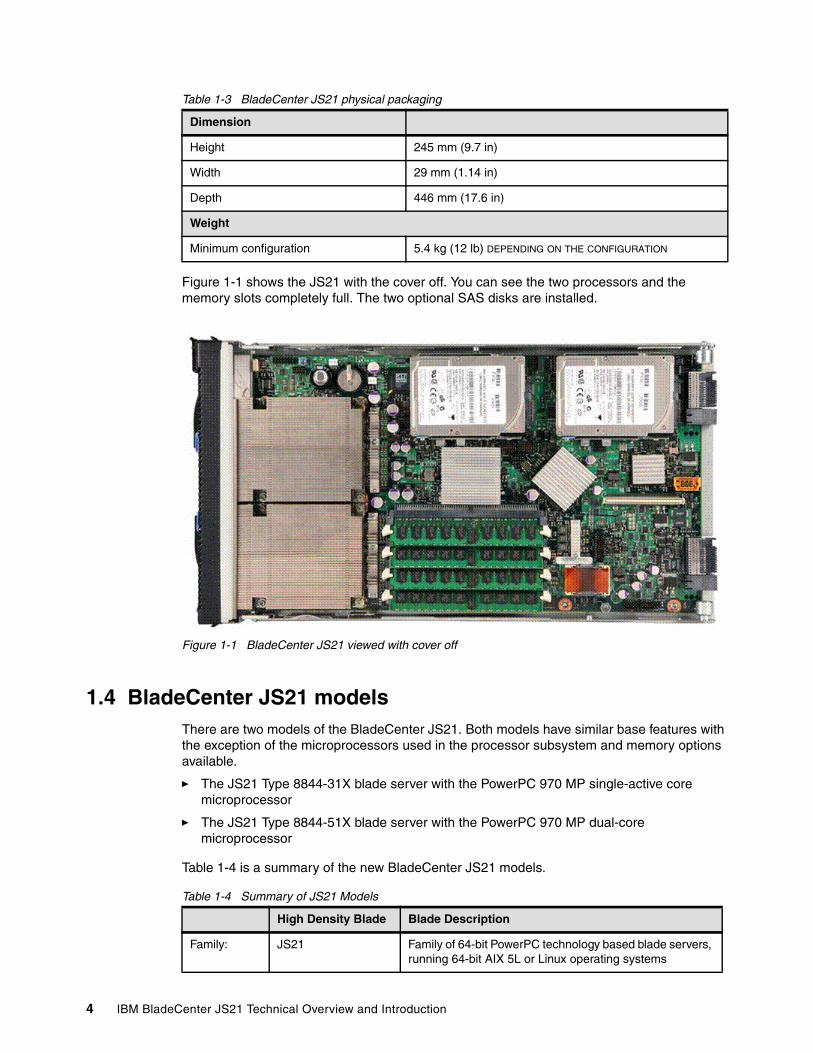
Table 1-3 BladeCenter JS21 physical packaging
Figure 1-1 shows the JS21 with the cover off. You can see the two processors and the memory slots completely full. The two optional SAS disks are installed.
Figure 1-1 BladeCenter JS21 viewed with cover off
1.4 BladeCenter JS21 modelsThere are two models of the BladeCenter JS21. Both models have similar base features with the exception of the microprocessors used in the processor subsystem and memory options available.
� The JS21 Type 8844-31X blade server with the PowerPC 970 MP single-active core microprocessor
� The JS21 Type 8844-51X blade server with the PowerPC 970 MP dual-core microprocessor
Table 1-4 is a summary of the new BladeCenter JS21 models.
Table 1-4 Summary of JS21 Models
Dimension
Height 245 mm (9.7 in)
Width 29 mm (1.14 in)
Depth 446 mm (17.6 in)
Weight
Minimum configuration 5.4 kg (12 lb) DEPENDING ON THE CONFIGURATION
High Density Blade Blade Description
Family: JS21 Family of 64-bit PowerPC technology based blade servers, running 64-bit AIX 5L or Linux operating systems
4 IBM BladeCenter JS21 Technical Overview and Introduction

1.5 Minimum and optional featuresTable 1-5 lists the standard configurations that the BladeCenter JS21 supports:
Table 1-5 Standard BladeCenter JS21 standard configuration
Figure 1-2 on page 6 shows memory, SAS Disk, and expansion option connectors, which are the same for the 31X and 51X.
Models: 8844-31X 2-core PowerPC 970 Blade- 2 x single active core PowerPC 970MP- 2 x 512 MB 400 MHz Memory DIMMsOperating frequency depends on the chassis type
8844-51X 4-core PowerPC 970 Blade- 2 x dual-core PowerPC 970MP- 2 x 1 GB 400 MHz Memory dual inline memory modules (DIMMs)Operating frequency depends on the chassis type
High Density Blade Blade Description
Model Processor L2 Cache Memory Ethernet HDD
8844-31X 2-socket single active core2.7 GHz/2.6 GHz
1 MB/ core 1GB (2x512 MB)
Dual Gigabit Open
8844-51X 2-socket dual-core2.5 GHz/2.3 GHz
1 MB/ core 2 GB (2x1 GB)
Dual Gigabit Open
Restriction: Processor frequency depends on the type of BladeCenter chassis the BladeCenter JS21 is installed in as described in Table 1-7 on page 8.
Chapter 1. General Description 5
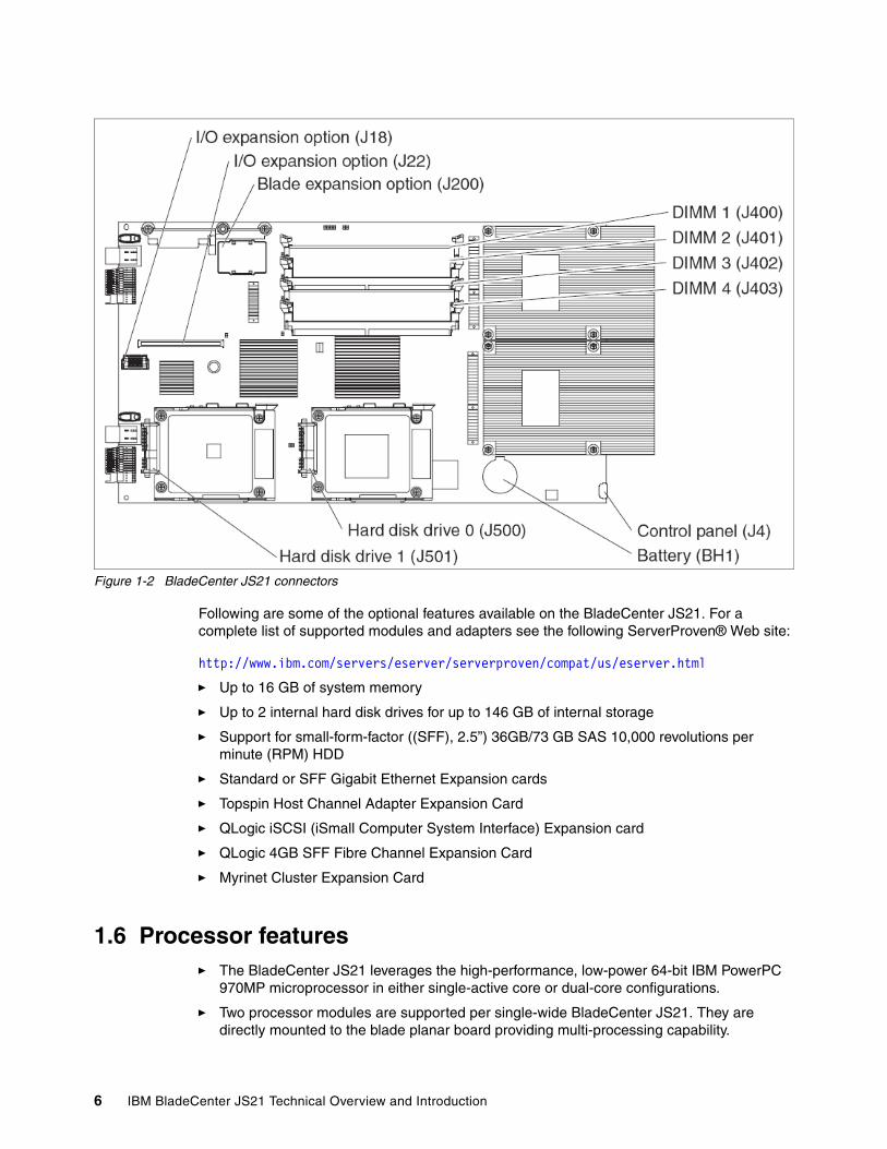
Figure 1-2 BladeCenter JS21 connectors
Following are some of the optional features available on the BladeCenter JS21. For a complete list of supported modules and adapters see the following ServerProven® Web site:
http://www.ibm.com/servers/eserver/serverproven/compat/us/eserver.html
� Up to 16 GB of system memory
� Up to 2 internal hard disk drives for up to 146 GB of internal storage
� Support for small-form-factor ((SFF), 2.5”) 36GB/73 GB SAS 10,000 revolutions per minute (RPM) HDD
� Standard or SFF Gigabit Ethernet Expansion cards
� Topspin Host Channel Adapter Expansion Card
� QLogic iSCSI (iSmall Computer System Interface) Expansion card
� QLogic 4GB SFF Fibre Channel Expansion Card
� Myrinet Cluster Expansion Card
1.6 Processor features� The BladeCenter JS21 leverages the high-performance, low-power 64-bit IBM PowerPC
970MP microprocessor in either single-active core or dual-core configurations.
� Two processor modules are supported per single-wide BladeCenter JS21. They are directly mounted to the blade planar board providing multi-processing capability.
6 IBM BladeCenter JS21 Technical Overview and Introduction

� Each processor core includes 32/64 KB L1(Data/Instruction) and 1 MB (non-shared) L2 cache.
� The 4-core configuration is comprised of two dual-core PowerPC 970MP processors while the 2-core configuration is comprised of two single-active core PowerPC 970 MP processors.
� The PowerPC 970 MP is the higher frequency, dual-core capable, 90 nm follow-on to the single-core capable PowerPC 970FX 2.2 GHz microprocessor used in the previous generation BladeCenter JS20.
� The processor operating frequency depends on the BladeCenter chassis, as shown in Table 1-7 on page 8.
1.7 Memory featuresThe BladeCenter JS21 supports 4 dual inline memory module (DIMM) slots with two-way interleaving for pairs of 400 MHz or 533 MHz DDR2 SDRAM DIMMs including ECC and Chipkill. The available DIMM sizes range from 512 MB to 4 GB. The minimum memory size on the BladeCenter JS21 is 1 GB and the maximum memory size is 16 GB. With two-way interleaving memory must be populated two DIMMs at a time, and the minimum requirement is two DIMMS.
The 2-core BladeCenter JS21 ships with 1 GB main memory (two PC2-3200 512 MB DIMMs). The 4-core BladeCenter JS21 ships with 2 GB main memory (two PC2-3200 1 GB DIMMs).
1.7.1 Memory DIMMsTable 1-6 lists the supported memory on the BladeCenter JS21.
Table 1-6 JS21 Support Memory DIMM types
1.8 Internal Serial Attached SCSI (SAS) DiskThe BladeCenter JS21 provides support for up to two internal hard disk drives.
DIMM Size PC2-3200 (400 MHz) PC2-4200 (533 MHz)
IBM PN Option PN FRU PN IBM PN Option PN FRU PN
512 MB 38L5914 73P2865 73P2869 38L5919 41Y2707 41Y2708
1 GB 38L5915 39M5809 39M5808 38L5920 41Y2711 41Y2710
2 GB 38L5916 39M5812 39M5811 38L5921 41Y2715 41Y2714
4 GB 38L5918 41Y2703 41Y2702 see note see note see note
Restriction: See 1.11, “Statement of direction” on page 13 concerning support of 4 GB PC2-4200 (533 MHz) memory.
Chapter 1. General Description 7

1.8.1 Hard Disk DrivesThe base BladeCenter JS21 does not ship with any hard disk drives. You can order up to two of the 2.5-inch SFF SAS hard disk drive options. The BladeCenter JS21 can have up to two 73 GB SAS hard disk drives for a maximum of 146 GB of internal storage or up to two of the 36 GB SAS hard disk drives. The BladeCenter JS21 also supports Redundant Array of Independent Disks (RAID 0 or 10) mirroring standard.
You do not have to install a hard disk drive if you installed the QLogic 4Gb SFF Fibre Channel Expansion Card and configured the BladeCenter JS21 to boot from storage area network (SAN). For more information about SAS hard drives refer to 2.7.1, “Serial Attached SCSI (SAS) storage subsystem” on page 22.
1.9 BladeCenter chassisThe core component of the BladeCenter infrastructure is the BladeCenter chassis. Each BladeCenter chassis occupies seven rack units. With an additional two rack units to accommodate high-speed switches, the BladeCenter H chassis occupies nine rack units. Up to six BladeCenter or up to four BladeCenter H chassis can be installed in a single 42U rack. The blade server processor operating frequency depends on the BladeCenter chassis into which it is installed, as shown in Table 1-7.
Table 1-7 processor operating frequency is dependent upon the BladeCenter chassis
See the statement of direction in 1.11, “Statement of direction” on page 13 concerning the BladeCenter T chassis.
BladeCenter chassis (8677)This BladeCenter is a 7U rack mountable chassis that contains bays for up to 14 blade servers, four power modules, two switch modules, and two Management Modules. Figure 1-3 on page 9 shows the front of the BladeCenter.
Restriction: Certain input/output (I/O) expansion cards installed may preclude the attachment of the second SAS hard disk drive unless the I/O expansion card is a small-form-factor (SFF) card. In this case both the SFF I/O expansion card and the second SAS HDD may be installed at the same time.
Chassis and Machine Type JS21 8844-31X JS21 8844-51X
BladeCenter (8677) 2.6 GHz 2.3 GHz
BladeCenter H (8852) 2.7 GHz 2.5 GHz
BladeCenter T (8720) 2.6 GHz 2.3 GHz
8 IBM BladeCenter JS21 Technical Overview and Introduction
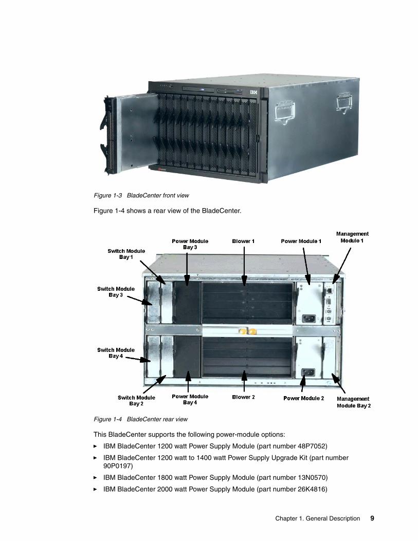
Figure 1-3 BladeCenter front view
Figure 1-4 shows a rear view of the BladeCenter.
Figure 1-4 BladeCenter rear view
This BladeCenter supports the following power-module options:
� IBM BladeCenter 1200 watt Power Supply Module (part number 48P7052)
� IBM BladeCenter 1200 watt to 1400 watt Power Supply Upgrade Kit (part number 90P0197)
� IBM BladeCenter 1800 watt Power Supply Module (part number 13N0570)
� IBM BladeCenter 2000 watt Power Supply Module (part number 26K4816)
Chapter 1. General Description 9
If the existing power modules are replaced with the 2000 watt power modules, you must upgrade the management module firmware. If two management modules are installed in the BladeCenter chassis, upgrade both management modules to the same level of firmware.
If a BladeCenter JS21 is being installed in the 8677-1xx/2xx BladeCenter, the Power Module Upgrade Guidelines will contain a table identifying the power load factor of all possible blades. You can find the guidelines at the following Web address:
http://www.ibm.com/pc/support/site.wss/document.do?sitestyle=ibm&lndocid=MIGR-53353
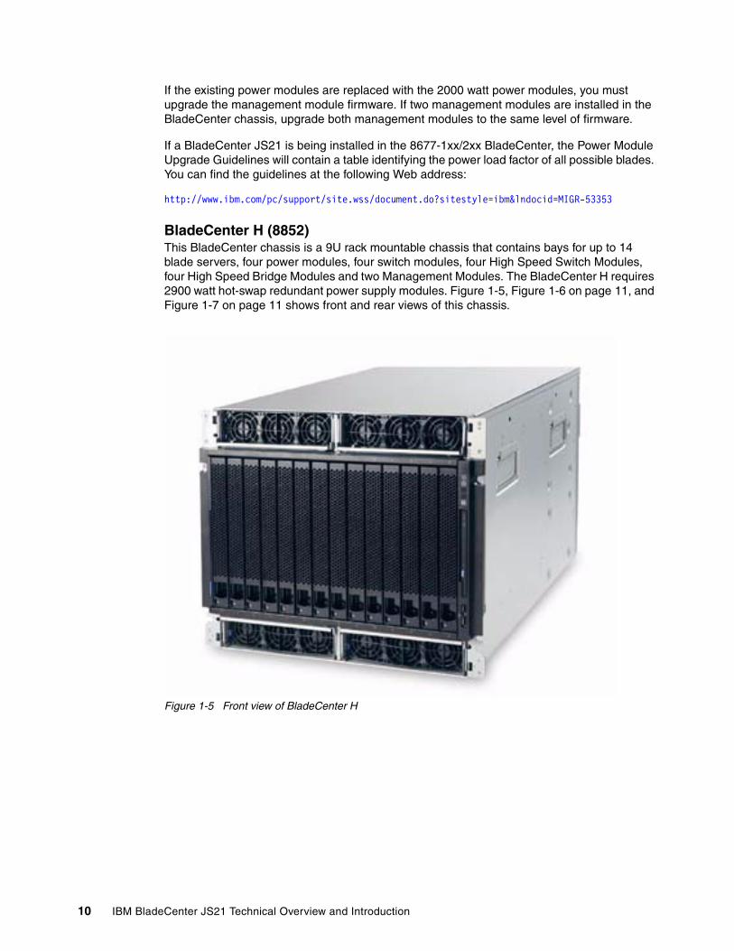
BladeCenter H (8852)This BladeCenter chassis is a 9U rack mountable chassis that contains bays for up to 14 blade servers, four power modules, four switch modules, four High Speed Switch Modules, four High Speed Bridge Modules and two Management Modules. The BladeCenter H requires 2900 watt hot-swap redundant power supply modules. Figure 1-5, Figure 1-6 on page 11, and Figure 1-7 on page 11 shows front and rear views of this chassis.
Figure 1-5 Front view of BladeCenter H
10 IBM BladeCenter JS21 Technical Overview and Introduction

Figure 1-6 Rear view of BladeCenter H
Figure 1-7 Rear view drawing of BladeCenter H
Chapter 1. General Description 11

BladeCenter chassis T (8720)This BladeCenter chassis is an 8U rack mountable chassis that meets the special needs of the telecommunications industry and is tested for Network Equipment Building Standards (NEBS) compliance. With its low-profile handles the BladeCenter JS21 is intended to be the first blade to be supported in all three chassis in the BladeCenter family. The BladeCenter T chassis requires 1300 watt hot-swap redundant power supply modules.
See the statement of direction in section 1.11, “Statement of direction” on page 13 concerning BladeCenter T.
1.9.1 BladeCenter Power ModulesThere are multiple versions of Power Supplies available. The BladeCenter JS21 supports the Power/Thermal Management Architecture of BladeCenter, Power Oversubscription is an option. There is no strict dependency of BladeCenter JS21 on the size or capacity of a particular Power Supply.
The standard redundant power supplies are installed in power bays one and two of the BladeCenter. They provide power to the first six blade server bays. To install blade servers in the remaining bays, seven through 14, you must install an additional pair of redundant power supply modules in power bays three and four.
The standard redundant power supplies are installed in power bays one and three of the BladeCenter H. They provide power to the first seven blade server bays. To install blade servers in the remaining bays, eight through 14, you must install an additional pair of redundant power supply modules in power bays two and four.
1.9.2 BladeCenter Management ModulesThe BladeCenter chassis contains two (redundant) Management Modules that provide the manageability interface for the BladeCenter chassis. The Management Module communicates with the BladeCenter JS21 within the BladeCenter via an RS-485 SAS HDD inter-management network. The BladeCenter JS21 supports both the standard IBM BladeCenter Management Module and the Advanced Management Module.
1.9.3 Media featuresThe BladeCenter chassis contains a media bay that contains one compact-disc read-only memory (CD-ROM) drive or digital video-disc read-only memory (DVD-ROM), a floppy diskette drive, and a Universal Serial Bus (USB) port that you can dynamically assign to any single BladeCenter JS21 in the BladeCenter chassis.
If your BladeCenter chassis was shipped before June 2003, an update to the interface card on the media tray may be required for proper CD-ROM operation with the BladeCenter JS21. To determine the part number of your existing media tray, from the Management Module Web interface, under the heading “Monitors” in the left column, select Hardware vital product data (VPD), and then look at the Module Name “media tray”. If the field-replaceable units (FRU) number of the media tray is 59P6629, call your hardware support center and request a free replacement media tray.
Restriction: Floppy drives are not supported as boot devices on the BladeCenter JS21.
12 IBM BladeCenter JS21 Technical Overview and Introduction

1.10 Serial over local area network (LAN)Serial over LAN (SoL) continues to be the primary serial console support for the BladeCenter JS21. SoL requires a subnet and underlying virtual local area network (VLAN) that is implemented by a LAN Switch I/O Module installed in I/O module Bay 1 of the BladeCenter chassis. The subnet and VLAN are entirely internal to each BladeCenter chassis and should not be externally accessible. The supported switch modules for SoL are Nortel Networks Gigabit Ethernet Switch Module and Cisco Systems Intelligent Gigabit Ethernet Switch Module and the SoL VLAN ID is 4095.
1.11 Statement of direction� IBM Eserver Cluster 1350 intends to support the JS21 in its future Cluster 1350 systems
during 2Q 2006.
� IBM intends to provide Cluster Systems Management (CSM) for AIX 5L, V1.5 and CSM for Linux on POWER, V1.5 support on the BladeCenter JS21 running AIX 5L V5.2, AIX 5L V5.3, Red Hat Enterprise Linux (RHEL) 4, and SUSE Linux Enterprise Server (SLES) 9. IBM plans to provide CSM support in a service update during 3Q 2006.
� IBM intends to support the JS21 in the IBM BladeCenter T for NEBS (Telco) environments during 3Q 2006.
� IBM intends to offer an 8 GB (2x4 GB) PC2-4200 DDR2 ECC SDRAM registered DIMM (RDIMM) 533MHz memory option for the JS21 BladeCenter during 3Q 2006.
All statements regarding IBM’s plans, directions, and intent are subject to change or withdrawal without notice. Any reliance on these Statements of General Direction are at the relying party's sole risk and will not create liability or obligation for IBM.
Chapter 1. General Description 13

14 IBM BladeCenter JS21 Technical Overview and Introduction
Chapter 2. Architecture and technical overview
This chapter discusses the overall system architecture that Figure 2-1 on page 16 represents. We describe the major components of this diagram in the following sections. The bandwidths provided throughout this section are theoretical maximums provided for reference. We recommend that you always obtain real-world performance measurements using production workloads.
2
© Copyright IBM Corp. 2006. All rights reserved. 15

Figure 2-1 BladeCenter JS21 logic data flow
Northbridge
Hyper-Transport
Tunnel
PowerPC970MP
PowerPC970MP
Southbridge
PC87427SuperIO
System Memory Banksx4 DIMMS @ 400/533 MHz
DDR2DDR2DDR2DDR2
2166SMP(IPMI)
Hi-Speed I/F
SAS ctrl
SAS HDD (1)SAS HDD (2)
MidPlane Conn A
HDM Header
Blade Exp Conn
RS485MPX SIO 1
(SoL)
ATIRN50
DDR64MB
TPM
dual GbEN
PCI-X @ 100 MHz
x8 PCI-express
16b HT @ 800 MHz
USB P1
x8 or 2 x4
8b HT @ 400 MHz
USB P2
USB P3
RGB
USB P0
Data A
PCI
Debug Console
RS232
Data B
SIO 2
LPC
MidPlane Conn B
HDM Header
Daughter Card
Northbridge
Hyper-Transport
Tunnel
PowerPC970MP
PowerPC970MP
Southbridge
PC87427SuperIO
System Memory Banksx4 DIMMS @ 400/533 MHz
DDR2DDR2DDR2DDR2DDR2DDR2DDR2DDR2
2166SMP(IPMI)
Hi-Speed I/F
SAS ctrl
SAS HDD (1)SAS HDD (2)
MidPlane Conn A
HDM Header
MidPlane Conn A
HDM Header
Blade Exp Conn
RS485MPX SIO 1
(SoL)
ATIRN50
DDR64MB
ATIRN50
DDR64MB
TPM
dual GbEN
PCI-X @ 100 MHz
x8 PCI-express
16b HT @ 800 MHz
USB P1
x8 or 2 x4
8b HT @ 400 MHz
USB P2
USB P3
RGB
USB P0
Data A
PCI
Debug Console
RS232
Data B
SIO 2
LPC
MidPlane Conn B
HDM Header
MidPlane Conn B
HDM Header
Daughter Card
16 IBM BladeCenter JS21 Technical Overview and Introduction

2.1 PowerPC 970MP ProcessorThe PowerPC 970 MP, as shown in Figure 2-2, is a single-chip / single-core or dual-core 64-bit PowerPC processor designed and manufactured by IBM. The BladeCenter JS21 8844-31X utilizes the single-active core PowerPC 970 MP. It provides high-performance processing through advanced superscalar design with multiple, pipelined execution units. Each core features a 64 KB L1 Instruction cache, 32 KB L1 Data cache and one MB L2 cache with 42-bit real addressing. The core supports a 32-bit native mode for 32-bit reduced instruction set computer (RISC) application code. This two-chip system connects to the NorthBridge by two unidirectional processor buses.
Figure 2-2 JS21 970 MP processor
In the 4-core model, the processor frequency can be set depending on the environment. The processor to NorthBridge bus ratio is always set at 2:1. Based on bi-directional 4 bytes per transfer, this results in a bandwidth capability of the Frontside Bus which is a multiple of four times the processor frequency in GHz. In addition to the core, an AltiVec engine is integrated to speed up parallelism for applications optimized for vector processing.
2.1.1 NorthBridgeThe NorthBridge provides the two Processor Interfaces to the processors, a double data rate 2 (DDR2) synchronous dynamic random access memory (SDRAM) interface to the 4 dual inline memory module (DIMM) sockets and a HyperTransport (HT) channel. It offers the following connections:
� Front Side Bus A - Processor Interface between 970 MP and NorthBridge
� Front Side Bus B - Processor Interface between 970 MP and NorthBridge
970MP
I/O Interfaces
L1 I Cache64K
Load Store Unit (2)
Integer Unit (2)
Floating Point
Unit (2)
AltiVecSIMDUnit
970 Processor Interface Bus Unit
L2 Cache 1MB
L1 D Cache32K
L1 I Cache64K
Load Store Unit (2)
Integer Unit (2)
Floating Point
Unit (2)
AltiVecSIMDUnit
L2 Cache 1MB
L1 D Cache32K
970MP
I/O Interfaces
L1 I Cache64K
Load Store Unit (2)
Integer Unit (2)
Floating Point
Unit (2)
AltiVecSIMDUnit
970 Processor Interface Bus Unit
L2 Cache 1MB
L1 D Cache32K
L1 I Cache64K
Load Store Unit (2)
Integer Unit (2)
Floating Point
Unit (2)
AltiVecSIMDUnit
L2 Cache 1MB
L1 D Cache32K
Chapter 2. Architecture and technical overview 17

� DDR2 SDRAM Bus - Interface to memory subsystem supporting error-checking and correction (ECC) and Chipkill. See 2.3, “Memory subsystem” on page 19 for the memory sizes and speeds available in the BladeCenter JS21.
� HyperTransport host bridge
2.1.2 HyperTransport tunnelHyperTransport technology is a high-speed, low-latency, point-to-point link designed to increase the communication speed between integrated circuits in computers, servers, embedded systems, and networking and telecommunications equipment up to 48 times faster than some existing technologies.
HyperTransport technology helps reduce the number of buses in a system, which can reduce system bottlenecks and enable today's faster microprocessors to use system memory more efficiently. HyperTransport technology connects the NorthBridge chip to the integrated Peripheral Component Interconnect-X (PCI-X) input/output (I/O) bridge chips, along to the SouthBridge chip. HyperTransport technology provides a high-speed, high-performance, point-to-point link for interconnecting integrated circuits on a board with a top signaling of 1.6 GBps on each wire pair. Table 2-1 describes the features and functions of the HyperTransport.
Table 2-1 HyperTransport Feature and Function Summary
The connection between NorthBridge and the Broadcom BCM5780 controller is 16-bits wide and runs at 800 MHz. Since HT uses a Double Data Rate scheme, the throughput is 2 bytes * 800 * 2 or 3.2 GB/s in the upstream and downstream direction. This gives a total throughput of 6.4 GB/s.
Feature/Function HyperTransport technology
Bus type Dual, unidirectional, point-to-point links
Link width 2, 4, 8, 16, or 32-bits
Protocol Packet-based with all packets multiple of four bytes (32- bits). Packet types include Request, Response, and Broadcast, any of which can include commands, addresses, or data.
Bandwidth (each direction) 100 to 6400 MB
Data Signaling Speeds 400 MHz to 1.6 GHz
Operating Frequencies 400, 600, 800, 1000, 1200, and 1600
Duplex Full
Max Packet Payload or Burst Length 64-byte packet
Power Management™ ACPI-compatible
Signaling 1.2-V Low-Voltage Differential Signaling (LVDS) with a 100-ohm differential impedance
Multiprocessing Support Yes
Environment Environment Inside the box
Memory model Coherent and noncoherent
18 IBM BladeCenter JS21 Technical Overview and Introduction
The connection between the BCM5780 and the SouthBridge is 1-byte wide, Double Data Rate, and runs at 200 MHz. Throughput is 1-byte * 200 * 2 or 400 MB/s. This results total throughput of 800 MB/s.
These values are maximum theoretical throughputs for comparison purposes only.
2.2 Cache StructureThe cache structure of the BladeCenter JS21 includes several on-chip caches to reduce memory latency when retrieving instructions and performing data load and store operations. The on-chip caches include:
� 64 KB direct-mapped instruction cache
� 32 KB 2-way set associative data cache
� 128-entry instruction effective to real address translation (ERAT) cache instructions
� 128-entry data ERAT cache
� 64-entry, fully associative segment lookaside buffer (SLB)
� 1024-entry 4-way set associative translation lookaside buffer (TLB)
� 1MB 8-way set associative, level 2-cache
2.3 Memory subsystemThe memory subsystem is comprised of the memory controller on the NorthBridge that provides the following:
� Two processor interfaces enterprise integration (EI) for the processors
� A DDR2 SDRAM memory interface to four DIMM sockets
� A HyperTransport channel
The memory controller uses two-way interleaving to increase the available peak memory bandwidth. The BladeCenter JS21 includes 1 GB of 400 MHz DDR2 memory (two 512 MB DIMMs) for the 8844-31X and 2 GB of 400 Mhz DDR2 memory (two 1 GB DIMMs) for the 8844-51X.
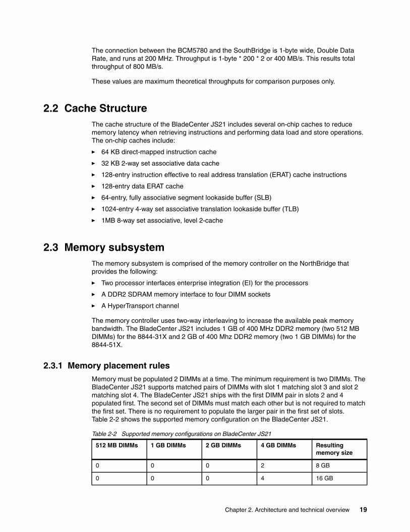
2.3.1 Memory placement rulesMemory must be populated 2 DIMMs at a time. The minimum requirement is two DIMMs. The BladeCenter JS21 supports matched pairs of DIMMs with slot 1 matching slot 3 and slot 2 matching slot 4. The BladeCenter JS21 ships with the first DIMM pair in slots 2 and 4 populated first. The second set of DIMMs must match each other but is not required to match the first set. There is no requirement to populate the larger pair in the first set of slots. Table 2-2 shows the supported memory configuration on the BladeCenter JS21.
Table 2-2 Supported memory configurations on BladeCenter JS21
512 MB DIMMs 1 GB DIMMs 2 GB DIMMs 4 GB DIMMs Resulting memory size
0 0 0 2 8 GB
0 0 0 4 16 GB
Chapter 2. Architecture and technical overview 19
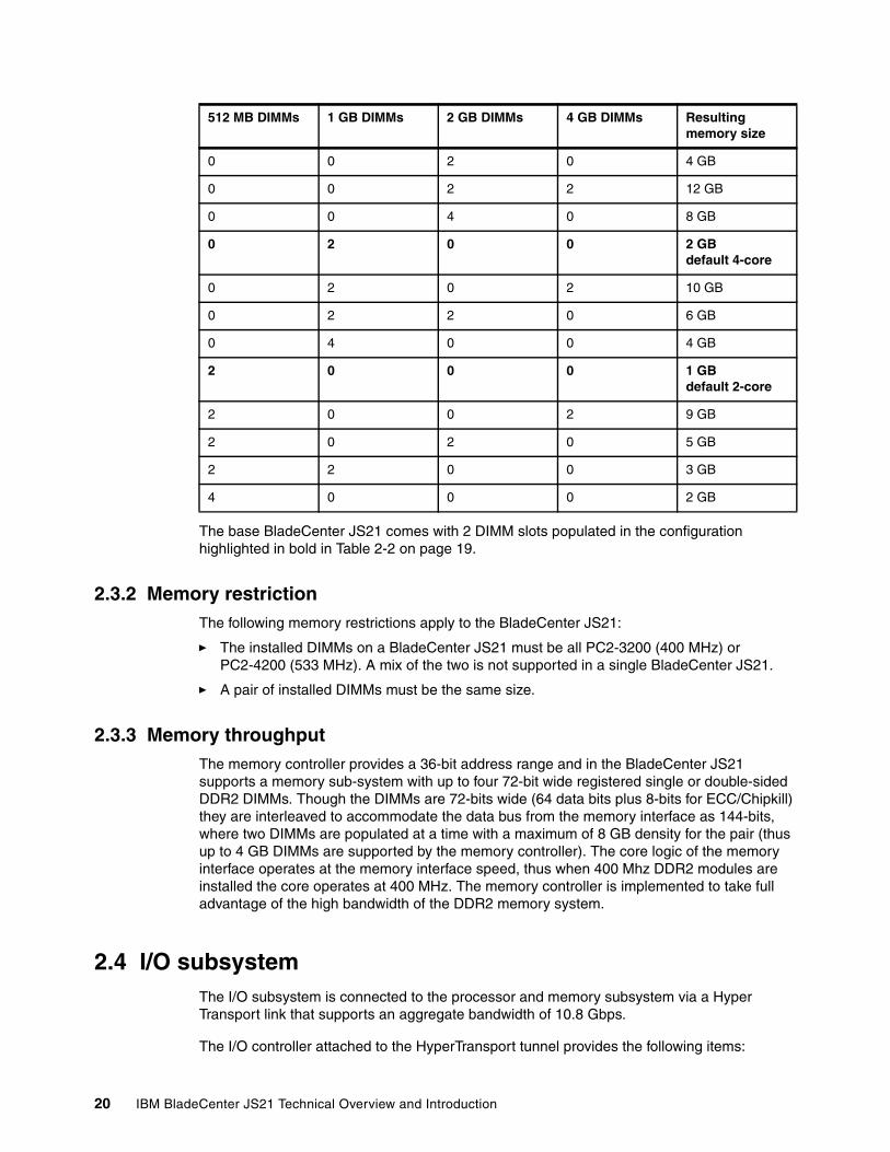
The base BladeCenter JS21 comes with 2 DIMM slots populated in the configuration highlighted in bold in Table 2-2 on page 19.
2.3.2 Memory restrictionThe following memory restrictions apply to the BladeCenter JS21:
� The installed DIMMs on a BladeCenter JS21 must be all PC2-3200 (400 MHz) or PC2-4200 (533 MHz). A mix of the two is not supported in a single BladeCenter JS21.
� A pair of installed DIMMs must be the same size.
2.3.3 Memory throughputThe memory controller provides a 36-bit address range and in the BladeCenter JS21 supports a memory sub-system with up to four 72-bit wide registered single or double-sided DDR2 DIMMs. Though the DIMMs are 72-bits wide (64 data bits plus 8-bits for ECC/Chipkill) they are interleaved to accommodate the data bus from the memory interface as 144-bits, where two DIMMs are populated at a time with a maximum of 8 GB density for the pair (thus up to 4 GB DIMMs are supported by the memory controller). The core logic of the memory interface operates at the memory interface speed, thus when 400 Mhz DDR2 modules are installed the core operates at 400 MHz. The memory controller is implemented to take full advantage of the high bandwidth of the DDR2 memory system.
2.4 I/O subsystemThe I/O subsystem is connected to the processor and memory subsystem via a Hyper Transport link that supports an aggregate bandwidth of 10.8 Gbps.
The I/O controller attached to the HyperTransport tunnel provides the following items:
0 0 2 0 4 GB
0 0 2 2 12 GB
0 0 4 0 8 GB
0 2 0 0 2 GBdefault 4-core
0 2 0 2 10 GB
0 2 2 0 6 GB
0 4 0 0 4 GB
2 0 0 0 1 GBdefault 2-core
2 0 0 2 9 GB
2 0 2 0 5 GB
2 2 0 0 3 GB
4 0 0 0 2 GB
512 MB DIMMs 1 GB DIMMs 2 GB DIMMs 4 GB DIMMs Resulting memory size
20 IBM BladeCenter JS21 Technical Overview and Introduction
� Integrated Broadcom 5780 with dual-gigabit Ethernet
� Peripheral Component Interconnect-Express (PCI-E) interface with 17 serial links
� Dual integrated 1GB Ethernet controllers
� One PCI-X bus
� Serial over LAN (Sol) for one serial/console port
Attached to the PCI-X bus is a PCI-X Expansion Card connector and the Serial Attached Small Computer System Interface (SCSI) (SAS) Redundant Array of Independent Disk (RAID) controller supporting up to 2 onboard hard drives.
2.4.1 PCI-ExpressPCI-Express (PCI-E) is the successor to Peripheral Component Interconnect (PCI) and PCI-X bus systems, realized by point-to-point implementation with the following general characteristics:
� Point-to-point serial interconnect with packetized, layered protocol
� 2.6 Gbits/s per-pin pair in each direction (speed scale in future generations)
� Dual simplex connection
� Scalable bus widths
� Embedded clocking technique using 8-bit/10-bit encoding
� Isochronous Data transfer support
� Compatible with PCI at the software layers
2.5 Universal Serial Bus (USB) SubsystemThe Universal Serial Bus (USB) Subsystem on BladeCenter JS21 is based off the USB controllers of the SouthBridge chip. There are two USB controllers—one is for Mass-Storage attachments like compact-disc read-only memory (CD-ROM) or digital video disc (DVD) (BladeCenter Media tray). Each USB controller provides two ports, each of which is wired to the midplane on different connectors to provide redundant connectivity into the optional, redundant Management Modules for high availability. The Management Module controls USB-attached devices in BladeCenter and access to them is arbitrated by the Management Module, via the USB switching function in BladeCenter.
The BladeCenter JS21 does not support USB redirection.
2.6 Mass StorageBladeCenter provides USB access to Mass Storage devices in the Media Tray. It supports Floppy, CD-ROM, digital video-disc read-only memory (DVD-ROM) and DVD-Combo drive as Mass Storage devices, but Floppy devices are not supported as boot devices on BladeCenter JS21.
2.7 StorageThe following section describes the storage options available on the BladeCenter JS21.
Chapter 2. Architecture and technical overview 21

2.7.1 Serial Attached SCSI (SAS) storage subsystemThe storage subsystem on the BladeCenter JS21 is based on the 2-port SAS controller attached to PCI-X bus running at 100 MHz. The sub-system provides RAID 0 or 10 mirroring functionality.
As RAID is considered an option, the disks are shipped “blank”, ready for use in Just a Bunch of Disk (JBOD) configuration. If you actually want to configure RAID for any onboard drives, run the RAID configuration tools first to prepare the disks to be used in a RAID configuration. In the event that RAID is configured, the drives are reformatted to 528-byte sector size, instead of 512-byte. RAID configuration occurs within the AIX 5L or Linux operating system. To configure a RAID array boot the AIX standalone diagnostics CD, and configure the RAID from there. This function is also available when booting into rescue mode on the SUSE Linux Enterprise Server (SLES) 9 SP3 install compact disc (CD).
Conversely, if a drive is formatted for RAID to 528-byte sector size, and you want to use them in a JBOD configuration, reformat the drives to 512-byte sector size as JBOD requires 512.
Serial Advanced Technology Attachment (SATA) drives are not supported as onboard local disk drives on BladeCenter JS21. The SAS subsystem does not support SCSI Enclosure Services (SES).
For additional information read the AIX 5L (SG23-1323) or Linux (SG23-1327) reference guides at the following Web site:
http://publib16.boulder.ibm.com/pseries/en_US/infocenter/base/HW_scsi_adapters.htm
2.8 Expansion cardsEach BladeCenter JS21 contains expansion option connectors that can expand the external I/O connectivity of the JS21. An expansion card installed in the expansion option connectors can access I/O modules installed in bays 3 and 4. See Figure 1-2 on page 6 to see expansion option connector locations.
Several supported expansion cards are described in more detail in the section that follows. For a complete list of supported expansion cards see this ServerProven Web site:
http://www.ibm.com/servers/eserver/serverproven/compat/us/eserver.html
or
http://www.ibm.com/servers/eserver/serverproven/compat/us/blade/8844.html
Cisco InfiniBand Host Channel Adapter expansion card (32R1896)The Cisco InfiniBand Host Channel Adapter expansion card can connect the BladeCenter JS21 to a high-performance computing environment. The Cisco InfiniBand Switch Module for blade servers delivers low-latency, high-bandwidth connectivity between InfiniBand connected blade servers, additional BladeCenter chassis, stand-alone servers, and external Gateways for connectivity to Ethernet local area networks (LANs) and Fibre Channel storage area networks (SANs). There must be a Cisco InfiniBand switch module in the BladeCenter.
Restriction: You can install a maximum of one expansion card in the BladeCenter JS21. When an expansion card is installed it may preclude the attachment of the second SAS hard disk drive unless the expansion card is a small-form-factor (SFF) card, in which case both the SFF expansion card and the second SAS hard disk drives (HDD) may be installed at the same time.
22 IBM BladeCenter JS21 Technical Overview and Introduction
QLogic iSCSI expansion card (26K6487)The QLogic iSCSI expansion card is a 64-bit, 133 MHz, 1 GB hardware initiator that provides iSCSI (SCSI over ethernet) communications between the BladeCenter JS21 and an iSCSI Storage Device. It is a dual-port card with full 1 GB ethernet functionality and can work as a straight network card but does not support Internet Protocol Security Architecture (IPSec). This card enables both modules bays 3 and 4 on the BladeCenter chassis. There must also be an ethernet switch module, Optical Pass-Thru module, or Copper Pass-Thru switch module in the BladeCenter.
Standard and SFF Gigabit Ethernet expansion card The Standard (73P9030) and SFF (26K4842) Gigabit Ethernet expansion cards increases the number of Gigabit Ethernet network interfaces on the BladeCenter JS21 from two to four for improved redundancy and failover protection. Both Gigabit Ethernet expansion cards provides two Gigabit Ethernet interfaces that are connected to I/O module bays 3 and 4. There must be either a LAN Switch I/O Module or the Optical Pass-Thru I/O Module in one or both of these I/O module bays to connect the Gigabit Ethernet interfaces on the expansion card to an external LAN.
QLogic 4 GB SFF Fibre Channel expansion card (26R0890)The QLogic 4 GB SFF Fibre Channel expansion card provides a higher bandwidth connection between the BladeCenter JS21 and SAN switches. The QLogic 4 GB SFF Fibre Channel expansion card allows for a true end-to-end 4 GB Fibre Channel blade server-to-SAN solution. This card is connected to the I/O module in bay 3 or 4. There must be a fibre channel switch module or Optical Pass-Thru module in bay 3 or 4 of the BladeCenter.
Myrinet Cluster expansion card (73P6000)The Myrinet Cluster expansion card can connect the BladeCenter JS21 to a Myrinet network. Myrinet networks are typically used to support certain types of High-Performance Computing (HPC) applications that distribute computation across a cluster of multiple servers.The Myrinet expansion card is hard wired to connect to I/O Module bay 4. The Optical Pass-Thru Module must be used in bay 4.
2.9 Supported I/O ModulesI/O modules enable connectivity between blade servers within the same chassis, blade servers in other chassis and the outside world. Up to four I/O modules can be installed in a BladeCenter chassis, one in each I/O Module bay. For a complete list of supported modules and adapters see this ServerProven Web site:
http://www.ibm.com/servers/eserver/serverproven/compat/us/eserver.html
The following I/O modules are supported with the BladeCenter JS21 with restrictions:
Restriction: If you plan to install an ethernet expansion card (standard or SFF), first install the operating system to allow the onboard ports to be recognized and configured before the ports on the expansion card. If you install the ethernet expansion card before you install the operating system, be aware that the expansion card ports are assigned before the onboard ports.
Note: Because of distinctions in operating system support, adapters supported on other IBM blade servers may not be supported on BladeCenter JS21. For more information about compatibility go to the following compatibility Web site:
http://www.ibm.com/pc/us/compat
Chapter 2. Architecture and technical overview 23

Ethernet Switch Modules The ethernet switch modules provides external interfaces for connecting to networks external to the BladeCenter. The Cisco Switch Modules connect to a single Gigabit Ethernet Interface on each installed blade server. You can use these switch modules in I/O Module bay 1 and 2. They can also be used in I/O Module Bays 3 and 4 as long as you have a Standard or SFF Gigabit Ethernet Expansion Card installed in the BladeCenter JS21.
The available Cisco Switch Modules are:
� Cisco Systems Fiber Intelligent Gigabit Ethernet Switch Module
� Cisco Systems Intelligent Gigabit Ethernet Switch Module
� Nortel Networks Layer 2-3 Copper Gigabit Ethernet Switch Module
� Nortel Networks Layer 2-3 Fiber Gigabit Ethernet Switch Module
� Nortel Networks Layer 2-7 Gigabit Ethernet Switch Modules
For more information on Ethernet Switch Modules visit the following Web site:
http://www.ibm.com/systems/bladecenter/switch/switch_ethernet_overview.html
SAN Switch ModulesThere are a variety of fibre channel switch modules available for the BladeCenter to simplify infrastructure complexity and manageability for the BladeCenter. The SAN Switch Modules provide external fibre channel interfaces for connecting to SANs external to the BladeCenter chassis. Internally the SAN Switch Modules connect to a single fibre channel interface on each installed BladeCenter JS21 that is equipped with a Fibre Channel expansion card. These switch modules can be used in I/O Module bays 3 and 4.
Following are the available SAN Switch Modules:
� Brocade 10 and 20 port SAN Switch Modules
� QLogic 10-port and 20-port 4 GB Fibre Channel Switch Modules
� McData 10-port and 20-port 4 GB Fibre Channel Switch Modules
� QLogic Enterprise 6-port Fibre Channel Switch Module
For more information on SAN Switch Modules visit the following Web site:
http://www.ibm.com/systems/bladecenter/switch/switch_fibrechannel_overview.html
InfiniBand Switch ModuleThere is one Infiniband channel switch module available for the BladeCenter to simplify infrastructure complexity and manageability for the BladeCenter. Scale-out DataCenters by interconnecting blades together with InfiniBand as the interconnect. Internally the InfiniBand Switch Module connects to a single InfiniBand interface on each installed BladeCenter JS21 that is equipped with an InfiniBand expansion card. These switch modules can be used in I/O Module bay 4.
The available InfiniBand Switch Modules is a Cisco Systems InfiniBand Switch Module.
For more information on SAN Switch Modules visit the following Web site:
http://www.ibm.com/systems/bladecenter/switch/switch_infiniband_overview.html
24 IBM BladeCenter JS21 Technical Overview and Introduction

2.10 Advanced Power ManagementThe growing variety of BladeCenter chassis with different environmental characteristics, as well as processors with different power requirements and thermal characteristics, generated the need for a more advanced management scheme of Power and Thermal characteristics within a datacenter environment. The Advanced Power and Thermal Management design of the IBM BladeCenter includes the following:
� Power Management for oversubscription
� Thermal Management
� Acoustic Management
The Advanced Power and Thermal Management supports power budget oversubscription and corresponding power policies. The BladeCenter JS21 receives a certain power budget from the BladeCenter Management Module that is based on the overall available power budget, the actual policy, the individual blade’s configuration, and the blade’s power throttling capacity.
The BladeCenter JS21 supports this Advanced Power and Thermal Management function.
2.10.1 Power Oversubscription in the BladeCenter environmentA blade may have to exist in an environment where a single power module (PM) cannot supply sufficient power to meet all the blades maximum power needs. In such an environment, the BladeCenter administrator has the option to enable a power policy known as “oversubscription”. Power oversubscription in the BladeCenter is the situation wherein the total maximum power needs for all blades and modules in a power supply’s domain is greater than what a single power module can provide, but within the capabilities of two load sharing power modules; however, the total limited power needs for all blades and modules in a power supply’s domain is less than or equal to what a single power module can provide. Figure 2-3 shows an example of power oversubscription.
Figure 2-3 Power Subscription
Chapter 2. Architecture and technical overview 25

Before a blade is allowed to power on, the total maximum power required by all blades and modules in a power module’s domain are calculated and depend on the domain power policy setting. The following behavior occurs:
� If the blade’s calculated power requirements (including all installed options) is at or below the nominal power capacity of a single power module, the blade is allowed to power on.
� If the domain’s power policy setting is Recoverable Oversubscription (redundant with performance impact) and the power requirements are such that the blade’s power allocation, including all installed options, would take the power domains power usage above the nominal power capacity of a single power module but within its recoverable oversubscription limit, then the blade is allowed to power on.
� If the domain’s power policy setting is No Oversubscription (redundant without performance impact), and the blades power allocation including all installed options would take the power domains power usage above the nominal power capacity of a single power module, the blade is not allowed to power on.
� If the domain’s power policy setting was Non Recoverable Oversubscription (nonredundant) and the blades power allocation including all installed options, would take the power domains power usage above 80% of twice the nominal power capacity of a single power module, the blade is not allowed to power on.
2.11 Trusted Platform ModuleThe BladeCenter JS21 supports the Trusted Platform Module (TPM), which provides the following four major functions:
� Asymmetric key functions like on-chip key pair generation, private key signatures, public key encryption, and privacy key decryption
� Secure storage of hash values representing platform configuration information in Platform Control Registers (PCRs) and secure reporting of these HASH values, as authorized by the platform owner, in order to enable verifiable attestation of the platform configuration based on the chain of trusted used in creating HASH values
� An Endorsement Key that you can use to anonymously establish that identify keys were generated in a TPM
� Initialization and management functions that allow you to turn functionality on and off, reset the chip, and take ownership, with strong controls
TPM on the BladeCenter JS21 can be enabled for Linux applications that require a protected key solution as provided by TPM. The device is presented in the hardware tree so that Linux can use it. For more information about TPM visit the following Web site:
http://www.trustedcomputinggroup.org
2.12 Logical partitioning and virtualizationLogical partitions (LPARs) and virtualization increases utilization of system resources. This section provides details and configuration specifications about this topic. The virtualization discussion includes virtualization enabling technologies that are standard on the system, such as the Performance Optimization with Enhanced RISC (POWER) Hypervisor, and optional ones, such as the virtual input/output server (VIOS) feature.
Restriction: At this time TPM is only supported by Linux.
26 IBM BladeCenter JS21 Technical Overview and Introduction

2.12.1 Dynamic logical partitioningThe BladeCenter JS21 does not support dynamic logical partitioning (DLPAR) on the client partitions. The BladeCenter JS21 utilizes the Integrated Virtualization Manager (IVM) of the Virtual I/O Server to manage the logical parition (LPAR) configuration. IVM does not support dynamic movement of system resources across client partitions that are operational.
You can reconfigure resources on client LPARs without recycling the whole server. IVM can be used to reconfigure resources across client LPARs if the LPARs are stopped. This dynamic movement of resources would not affect other LPARs that are running.
2.12.2 VirtualizationWith the introduction of more advanced POWER processors, partitioning technology moved from a dedicated resource allocation model to a virtualized shared resource model. This partitioning technology called Advanced POWER Virtualization, the same virtualization capability supported on the System p5 servers, is built into the PowerPC 970MP processor, making the JS21 the first IBM blade server with native virtualization. As an added incentive a customer may obtain a license for Virtual I/O Server to activate all virtualization features of the JS21 at no additional cost above the cost of the blade (mandatory software maintenance agreement not included). This section briefly discusses the key components of virtualization on BladeCenter JS21 servers.
For more information about virtualization, see the following Web site:
http://www.ibm.com/servers/eserver/about/virtualization/
POWER HypervisorCombined with features designed into the PowerPC 970MP, the POWER Hypervisor delivers functions that enable other system technologies, including Micro-Partitioning™, virtualized processors Institute of Electrical and Electronics Engineers (IEEE) virtual local area network (VLAN), compatible virtual switch, virtual SCSI adapters, and virtual consoles. The POWER Hypervisor is a component of system firmware that is always active, regardless of the system configuration; therefore, it requires no separate license apart from the VIOS for setup and usage.
The POWER Hypervisor provides the following functions:
� Provides an abstraction layer between the physical hardware resources and the logical partitions using them.
� Enforces partition integrity by providing a security layer between logical partitions.
� Controls the dispatch of virtual processors to physical processors.
� Saves and restores all processor state information during logical processor context switch.
� Controls hardware I/O interrupt management facilities for logical partitions.
� Provides virtual LAN channels between logical partitions, which removes the need for physical Ethernet adapters for inter-partition communication.
The following three types of virtual I/O adapters are supported by the POWER Hypervisor.
Virtual SCSIThe BladeCenter JS21 blade server uses SCSI as the mechanism for virtual storage devices. This is accomplished using two paired adapters: a virtual SCSI server adapter and a virtual SCSI client adapter. Virtual SCSI is available with the Advanced POWER Virtualization and
Chapter 2. Architecture and technical overview 27
optional Virtual I/O Server feature, which we described in section 2.12.3, “Advanced POWER Virtualization” on page 28.
Virtual EthernetThe POWER Hypervisor provides a virtual Ethernet switch function that allows partitions on the same server as a means for fast and secure communication. Virtual Ethernet working on LAN technology allows a transmission speed in the range of 1 to 3 GBps depending on the maximum transmission unit (MTU)1 size. Virtual Ethernet requires a BladeCenter JS21 running either AIX 5L Version 5.3 or the level of Linux supporting virtual Ethernet devices. Virtual Ethernet is part of the base system configuration.
Following are the Virtual Ethernet features:
� A partition supports two virtual Ethernet connections. Each virtual Ethernet connection can be connected to one of four virtual local area networks. The VLAN provides connectivity to other virtual Ethernet connections on client LPARs or the VIOS.
� Each partition operating system detects the virtual local area network switch as an Ethernet adapter— without the physical link properties and asynchronous data transmit operations. Layer-2 bridging to a physical Ethernet adapter is also included in the virtual Ethernet features on the VIOS LPAR.
Virtual teletypewriter (TTY) consoleEach partition needs access to a system console. Tasks such as operating system installation, network setup, and some problem analysis activities require a dedicated system console. The POWER Hypervisor provides the virtual console using a virtual TTY or serial adapter and a set of Hypervisor calls to operate on them.
The operating system console is provided by a console session with the Integrated Virtualization Manager.
2.12.3 Advanced POWER VirtualizationThe Virtual I/O Server version 1.2.1 feature is an optional feature available at no additional cost over the price of the base blade. Although included in the base price, the client must still
1 Maximum transmission unit
Note: Virtual Ethernet is based on the IEEE 802.1Q VLAN standard. No physical I/O adapter is required when creating a VLAN connection between partitions, and no access to an outside network is required. The Integrated Virtualization Manager (IVM) simplifies the virtual ethernet configuration by controlling the VLAN numbers. Simplifying this for the user results in restrictions where you do not have access to other IEEE 802.1Q capabilities such as assigning one virtual ethernet interface to multiple VLANs.
Note: The POWER Hypervisor is active when the server is running in partition and non-partition mode. Consider the Hypervisor memory requirements when planning the amount of system memory required. In AIX 5L V5.3 use the lshwres command to view the memory usage.
lshwres -r mem --level sys -F sys_firmware_mem
You can also determine this using the console of the Integrated Virtualization Manager: View/Modify Partitions -> System Overview -> Reserved Firmware Memory
28 IBM BladeCenter JS21 Technical Overview and Introduction

obtain a VIOS license for each JS21. This feature enables the implementation of logical partitions on BladeCenter JS21 servers.
The Virtual feature includes installation image for the Virtual I/O Server software that supports the following:
– Ethernet adapter sharing
– Virtual SCSI Server
– VIO software ships on a DVD
– Software support of
• AIX 5L V5.3
• SUSE Linux Enterprise Server 9 (SLES 9) for POWER
• Red Hat Enterprise Linux (RHEL) AS 3 for POWER, Update 2 or later (RHEL AS 3)
• Red Hat Enterprise Linux AS 4 for POWER (RHEL AS 4)
– Partition management using Integrated Virtualization Manager (IVM) (VIOS Version 1.2.1 or later)
For details about Advanced POWER Virtualization and virtualization in general, visit the following Web site:
http://www.ibm.com/servers/eserver/pseries/ondemand/ve/resources.html
Micro-Partitioning technologyThe concept of Micro-Partitioning allows the resource definition of a partition to allocate fractions of processors to the partition. Micro-Partitioning is only available with POWER5™ systems and the BladeCenter JS21. From an operating system perspective, a virtual processor is indistinguishable from a physical processor unless the operating system was enhanced to be aware of the difference. The firmware on the BladeCenter JS21 (host firmware) virtualizes the physical central processing units (CPUs). The host firmware layer presents logical CPU numbers (0-3) to the operating systems.
A partition can be defined with a processor capacity as small as 10 processor units. This represents one-tenth of a physical processor. The shared processor partitions are dispatched and time-sliced on the physical processors under control of the POWER Hypervisor. The shared processor partitions are created and managed by the Integrated Virtualization Management (included with Virtual I/O Server Version software 1.2.1 or later). Dedicated and micro-partitioned processors can co-exist on the same BladeCenter JS21 blade server as long as they are available. Table 2-3 lists processor partitioning information related to the BladeCenter JS21.
Table 2-3 Processor partitioning overview of the BladeCenter JS21
The maximums stated in Table 2-3 are supported by the hardware; however, the practical limits based on production workload demands and application utilization might be significantly lower.
Partitioning implementation JS21
Cores (maximum configuration) 4
Dedicated processor partitions (maximum configuration) 4
Shared processor partitions (maximum configuration) 40
Chapter 2. Architecture and technical overview 29

Virtual I/O ServerThe Virtual I/O Server is a special purpose partition that provides virtual I/O resources to client partitions. The Virtual I/O Server owns the real resources that are shared with the other LPARs. The Virtual I/O technology allows one or more partitions to share a physical adapter assigned to a partition. This enables you to minimize the number of physical adapters. The Virtual I/O Server eliminates the requirement that every partition owns a dedicated network adapter, disk adapter, and disk drive.
Figure 2-4 shows an organization view of Micro-Partitioning, including the Virtual I/O Server. The figure also includes virtual SCSI and Ethernet connections and mixed operating system partitions.
Figure 2-4 Virtual partition organization view
Because the Virtual I/O Server is an AIX 5L V5.3 operating system-based appliance, redundancy for physical devices attached to the Virtual I/O Server can be provided by using capabilities such as Multipath I/O and IEEE 802.3ad Link Aggregation.
You install the Virtual I/O Server partition from a special bootable DVD that is provided when you order the Virtual I/O Server. This dedicated software is only for the Virtual I/O Server operations, so the Virtual I/O Server software is only supported in Virtual I/O Server partitions.
The Virtual I/O Server can be installed by the following:
� Media (assigning the DVD-ROM drive to the partition and booting from the media)
� Using the Network Install Manager (NIM)
Note: The Virtual I/O Server supports logical mirroring and RAID configurations. Logical volumes created on RAID or JBOD configurations are bootable, and the number of logical volumes is limited to the amount of storage available and the architectural limits of the Logical Volume Manager.
30 IBM BladeCenter JS21 Technical Overview and Introduction
The following two major functions are provided with the Virtual I/O Server: a shared Ethernet adapter and Virtual SCSI.
Shared Ethernet Adapter A Shared Ethernet Adapter (SEA) is a new service that acts as a layer 2 network switch to route network traffic from a virtual Ethernet to a real network adapter. The shared Ethernet adapter must be assigned to the Virtual I/O Server partition.
Virtual SCSI Access to real storage devices is implemented through the Virtual SCSI services, a part of the Virtual I/O Server partition. This is accomplished using a pair of virtual adapters: a virtual SCSI server adapter and a virtual SCSI client adapter. The virtual SCSI server (target) adapter is responsible for executing any SCSI commands it receives. It is owned by the Virtual I/O Server partition. The virtual SCSI client adapter allows the client partition to access standard SCSI devices and LUNs that are assigned to the client partition.
All current storage device types, such as SAN, SCSI, and RAID, are supported. iSCSI and Serial Storage Architecture (SSA) are not supported.
For more information about the specific storage devices supported, visit the following Web site:
http://techsupport.services.ibm.com/server/vios/home.html
Integrated Virtualization ManagerIn order to ease virtualization technology adoption in the BladeCenter JS21 environment, IBM developed Integrated Virtualization Manager (IVM), a simplified hardware management solution that inherits most Hardware Management Console (HMC) features, but is limited to managing a single server to avoid the need for a dedicated control workstation. The goal is to provide a very simple solution that enables the administrator to reduce system setup time and to make hardware management even simpler.
The IVM provides a simple management model for a single system such as a BladeCenter JS21. Although it does not provide the full flexibility of an HMC, it enables the exploitation of the IBM Virtualization Engine™ technology. The BladeCenter JS21 is ideally suited for management via the IVM.
The HMC, which is designed to manage IBM System p servers with POWER5 processors, does not support the BladeCenter JS21 with the PowerPC 970MP processor.
IVM is an enhancement of Virtual I/O Server offered as part of Virtual I/O Server Version 1.2.1, which is the product that enables I/O virtualization in certain Power Architecture™ systems. It provides the same Virtual I/O Server features plus a Web-based graphical interface that enables the administrator to remotely manage the BladeCenter JS21 server with an Internet browser.
The IVM provides the following basic logical partitioning functions:
� Logical partitioning configuration
� Boot, start, and stop actions for individual partitions
� Display of partition status
� Management of virtual Ethernet
� Management of virtual storage
� Basic system management
Chapter 2. Architecture and technical overview 31
The requirements for an IVM managed server are as follows:
� IVM (with Virtual I/O Server) must be installed as the first operating system.
� An IVM partition requires a minimum of one virtual processor and 512 MB of random access memory (RAM).
The major limitations of IVM in comparison to an HMC-managed system are as follows:
� All adapters are owned by IVM, and LPARs use virtual devices only.
� No dynamic resource changes are allowed.
� There are only four virtual Ethernet networks available inside the system.
� Each LPAR can have a maximum of one Virtual SCSI adapter assigned.
� It is not possible to have redundant Virtual I/O Servers because IVM manages all I/O.
Despite those limitations, IVM provides advanced virtualization functionality without the need for an extra-cost workstation. For more information about IVM functionality and best practices, see Virtual I/O Server Integrated Virtualization Manager, REDP-4061.
2.13 Operating system supportThe BladeCenter JS21 supports the AIX 5L, Red Hat Enterprise Linux, and Novell SUSE Linux Enterprise Server operating systems.
2.13.1 AIX 5LThe following versions of AIX 5L are supported on the BladeCenter JS21:
� AIX 5L V5.2 with the 5200-08 Maintenance Package (APAR IY77270) plus APAR IY80499
� AIX 5L V5.3 with the 5300-04 Maintenance Package (APAR IY77273) plus APAR IY80493
For AltiVec-optimized AIX 5L development the following applications are needed:
� IBM XL C Enterprise Edition V8.0 for AIX 5L
� IBM XL C/C++ Enterprise V8.0 for AIX 5L
� IBM XL Fortran Enterprise Edition V10.1 for AIX 5L
� AIX 5L V5.3 with 5300-04
IBM periodically releases maintenance packages for the AIX 5L operating system. These packages are available on CD-ROM, or you can download them from the following Web site:
http://www.ibm.com/servers/eserver/support/unixservers/aixfixes.html
The Web page provides information about how to obtain the CD-ROM. You can also get individual operating system fixes and information about obtaining AIX 5L service at this site.
In AIX 5L V5.3, the suma command is also available, which helps the administrator to automate the task of checking and downloading operating system downloads. For more information about the suma command functionality, visit the following Web site:
http://techsupport.services.ibm.com/server/suma/home.html
If you have problems downloading the latest maintenance level, ask your IBM Business Partner or IBM representative for assistance.
32 IBM BladeCenter JS21 Technical Overview and Introduction
2.13.2 LinuxThe following versions of Linux are supported on the BladeCenter JS21:
� Novell SUSE Linux Enterprise Server 9 for IBM POWER Service Pack 3
� Red Hat Enterprise Linux 4 for IBM POWER Series Update 3
For AltiVec-optimized Linux development the following applications are needed:
� IBM XL C/C++ Advanced Edition V8.0 for Linux
� IBM XL Fortran Advanced Edition V10.1 for Linux
For information about the features and external devices supported by Linux on the BladeCenter JS21 visit the following Web site:
http://www.ibm.com/servers/eserver/pseries/linux/
For information about SUSE Linux Enterprise Server 9, visit the following Web site:
http://www.novell.com/products/linuxenterpriseserver/
For information about Red Hat Enterprise Linux, visit the following Web site:
http://www.redhat.com/software/rhel/details/
Many of the features described in this document are operating system dependent and might not be available on Linux. For more information, visit the following Web site:
http://www.ibm.com/systems/p/software/whitepapers/linux_overview.html
2.14 Systems ManagementThere are several tools available to manage BladeCenter JS21 blade servers. The BladeCenter Web interface can effectively manage the blades. In addition, IBM Director and Cluster Systems Management (CSM) are management tools that can manage your environment. See 1.11, “Statement of direction” on page 13 for information concerning support for the BladeCenter JS21 by these system management products.
2.14.1 BladeCenter Web InterfaceThe BladeCenter Web interface allows the following:
� System Administrators can easily and effectively manage up to 14 blade servers from an integrated interface.
� You can also power the BladeCenter JS21 on or off.
� You can perform firmware management.
� You to have powerful control over all blade servers and input/output (I/O) modules that are attached to the BladeCenter chassis even with a mixed environment.
Note: SMS menus are supported on the BladeCenter JS21. IBM only supports the Linux systems of clients with a SupportLine contract covering Linux. Otherwise, contact the Linux distributor for support.
Note: IBM only supports the Linux systems of clients with a SupportLine contract covering Linux. Otherwise, contact the Linux distributor for support.
Chapter 2. Architecture and technical overview 33

� You can manage other BladeCenter resources such as I/O modules and retrieval of system health information.
� You can configure SoL for the JS21 blade server.
2.14.2 IBM Director IBM Director is a graphical user interface (GUI) based management tool that provides management functions for the BladeCenter. IBM Director enables you to remotely manage many IBM and non-IBM servers including the BladeCenter JS21. The IBM Director console allows System Administrators to manage multiple BladeCenter chassis in a heterogeneous environment or environments where a Director infrastructure exists.
IBM Director V5.1 supports the following functions on the BladeCenter JS21:
� Events
� Resource monitoring
� Inventory (limited)
� Remote session
� Software distribution
� File transfer
� Process management
� MPA
Visit the following Web site to download IBM Director 5.1:
http://www.ibm.com/servers/eserver/xseries/systems_management/ibm_director/
2.14.3 Cluster Systems ManagementIBM Cluster Systems Management (CSM) provides several useful functions to manage a cluster from a single point-of-control. These include resource monitoring, automated monitoring and operation, remote hardware control, remote command execution, security, configuration file management, parallel network installation, and diagnostics.
CSM V1.5 supports the following functions on the BladeCenter JS21:
� Hardware control
� Install and update software on nodes
� Distributed command execution
� File synchronization across cluster
� Monitoring synchronization across cluster
� Monitoring and automated response
� Automatic security configuration
� Management of node groups (static and dynamic)
� Diagnostics tools
For more information about CSM visit the following Web site:
http://www.ibm.com/servers/eserver/clusters/software/
34 IBM BladeCenter JS21 Technical Overview and Introduction

Chapter 3. Reliability, availability, and serviceability
This chapter provides detailed information about the BladeCenter JS21 Type 8844 blade server’s reliability, availability, and serviceability (RAS) features. It describes several features that are available when using IBM AIX 5L. Support of these features using Linux can vary.
3
© Copyright IBM Corp. 2006. All rights reserved. 35

3.1 Reliability, fault tolerance, and data integrityThe reliability of the BladeCenter JS21 starts with components, devices, and subsystems that are fault tolerant. During the design and development process these subsystems go through a rigorous verification and integration testing process to help ensure the highest level of product quality.
Component features include the following:
� Transparent central processing unit (CPU) hardware error recovery (for example, for L2 cache errors)
� Memory scrubbing
� Dual inline memory module (DIMM) failure isolation for component errors (CE), DIMM pair isolation for unrecoverable errors (UE)
� Memory chip kill
� Peripheral Component Interconnect (PCI) bus parity
Blade level features include the following:
� Degraded boot support (memory, CPUs)
� Auto Server Recovery/Restart (automatic reboot after boot hangs or detected checkstop conditions)
� Environmental monitors and alerts
� System vital product data (VPD) and VPD on all major electronic components
� Field-replaceable units (FRU) or customer-replaceable unit (CRU) level light-emitting diodes (LEDs)
� Storage management subsystem (SMS) menu support
BladeCenter based features include the following:
� Redundant (n+n) power supplies
� Power Supply error detection
� Remote power control
� System event logs
� Redundant blowers, switches, Management Modules
� Hotplug of all BladeCenter FRUs (blowers, switches, power supplies) reliability, fault tolerance, and data integrity
3.1.1 Hardware Error HandlingThe BladeCenter JS21 can detect errors and prevent data integrity problems. Following are the different categories for hardware detected errors:
� Recovered by hardware autonomously
� Reported as machine checks that are recovered with the help of firmware
� Not recovered at all. Unrecoverable errors either lead to machine checks or to checkstop alerts, depending upon the severity.
36 IBM BladeCenter JS21 Technical Overview and Introduction
3.1.2 Boot Time DiagnosticsBoot time diagnostics provide checkout of the hardware at system initialization. Power-On Self-Test (POST) functions test out some of the system components and their interconnections. This is the same strategy employed with the previous generation JS20. The implementation was enhanced for the JS21 to cover new items like the video controller and the TPM. Logic built-in self-tests (LBIST) and array built-in self-tests (ABIST) are not run during power on reset on the blades.
Memory is tested using hardware assists (“scrubbing”) in the memory controller to run cell tests on each bank of memory. A “scrub immediate” function is executed at every power-on (system boot-up) to check for uncorrected errors. It also checks for a large number of single-bit errors on the same bit. A “background scrub” is activated for steady state while the system is operating, and is configured to scrub all memory within a 24 hour time period.
3.1.3 Standalone DiagnosticsThe standalone, bootable diagnostics are based on PC-Doctor running under Disk Operating System (DOS) on the Intel-based and Advanced Micro Devices (AMD)-based IBM blade servers. This is not supported on the for BladeCenter JS21. The eServer™ Standalone Diagnostic compact disc (CD) (which is based on AIX 5L) is provided for the BladeCenter JS21. Use the eServer Standalone Diagnostic CD if the blade cannot boot to the operating system from disk, or if the operating system is Linux.
Following are some of the functions provided by the Standalone Diagnostic CD:
� Analysis of errors reported by platform (CPU, memory)
� Testing of resources (input/output (I/O) adapters, devices)
� Service Aids (Firmware update, format disk, Redundant Array of Independent Disks (RAID) Manager)
3.1.4 Runtime DiagnosticsRuntime diagnostic functions depend on the operating system that is running.
Blades running AIX 5LThe service provider should run AIX 5L concurrent diagnostics if the operating system is functioning. Following are some of the functions provided by the disk-based AIX 5L diagnostic:
� Automatic runtime error log analysis
� Analysis of errors reported by platform (CPU, Memory, etc.)
� Testing of resources (I/O devices, etc.)
� Service Aids (Firmware update, format disk, etc.)
Blades running LinuxTo enable a number of RAS features, install service aids for Linux (Service toolkit) from the following Website:
http://techsupport.services.ibm.com/server/lopdiags
Restriction: The BladeCenter JS21 only supports standalone or concurrent diagnostic support with AIX 5L.
Chapter 3. Reliability, availability, and serviceability 37

These tools include the following:
� The update_flash command for installing system firmware updates.� The serv_config command for modifying various serviceability policies.� The usysident and usysattn utilities for manipulating system LEDs.� The bootlist command for updating the list of devices from which the system will boot.� The snap command for capturing extended error data to aid analysis of intermittent errors.� lsvpd, lscfg, and lsmcode commands, along with a boot-time scanning script called
update-lsvpd-db, constitute a hardware inventory system.� The lsvpd command provides Vital Product Data (VPD) about hardware components to
higher-level serviceability tools.� The lscfg command provides a more human-readable format of the VPD, as well as
some system-specific information.
The Error Log Analysis (ELA) toolThe ELA tool provides automatic analysis and notification of errors reported by the platform firmware. ELA analyzes errors written to /var/log/platform. If a corrective action is required, notification is sent to users subscribed for notification via the file /etc/diagela/mail_list.
The I/O Error Log Analysis provides automatic analysis and notification of I/O errors. I/O errors are written to evlog, and notification is sent to users subscribed for notification. The Serviceable Event contains a System Reference Code (SRC). These codes are documented in the Hardware Maintenance Manual.
The evlog-drv-tmpl tool requires evlog-1.6.0-xx (shipped with SUSE Linux Enterprise Server (SLES) 9). This revolutions per minute (RPM) does the following:
� Installs the driver templates for bcm5700, e100, e1000, emulex, ipr, olympic, and pcnet32. � Updates evlog ELA scripts. � Updates the evlog startup script to load or unload ELA rules during boot and shutdown.
After installation, restart evlog to load these new ELA rules. To restart evlog, run the following command:
/ets/init.d/evlog restart
3.1.5 I/O DiagnosticsStandalone Diagnostics test supported I/O adapters and devices.
3.1.6 Machine Check Handling and Dump SupportHost firmware handles machine checks and supports dump activities.
Machine CheckIn general, host firmware handles reported machine checks. When a machine check occurs, the error is analyzed to identify the failing device. When the hardware state permits, an error log is reported to the Management Module error log.
If the error occurred during hypervisor activities, a system reboot is initiated. When in partitioned mode with the error occurring during partition activity, a firmware assisted non-maskable interrupt (FWNMI) surfaces to the partition.
DumpBoth partition dump (when running in partitioned mode) and platform dump are supported on the BladeCenter JS21. Each can be performed by host firmware without the help of the
38 IBM BladeCenter JS21 Technical Overview and Introduction
on-board service processor. This implies that for platform dump, all hardware state information that cannot be retrieved in-band by host firmware is not part of the dump. Also, a platform dump is not possible if host firmware is no longer operating, for example, in case of a processor check stop.
3.2 ServiceabilityThe IBM BladeCenter chassis allows for flexible client setup of the blade servers and for the subsequent addition of most features (adapters and devices) to the BladeCenter JS21.
3.2.1 Hardware Maintenance Manual (HMM)The Hardware Maintenance Manual (HMM) is an integral part of the maintenance package on the blades. In some cases, hardware copy maintenance analysis procedures (MAPs) were developed to aid in service issue isolation, similar to the minimum configuration MAPs used on IBM system p today. These MAPs instruct the technician to remove components, and then re-boot the blade to see if the symptom changes. This leads to the failing FRU/CRU. The HMM also provides instructions for updating system firmware, reviewing operating system error logs, and other procedures to aid in problem isolation.
3.2.2 Light Path DiagnosticsLight path diagnostics are supported on the BladeCenter JS21. There are no menus or diagnostic service aids to test, turn on, or turn off the LEDs. There are LED Test, LED Set, and LED Request commands that can be used for testing purposes.
The BladeCenter JS21 follows the xSeries® LED strategy rather than the new converged xip LED strategy. This is basically a “Fault LED” strategy. The CPU’s system board and memory diagnostics are provided by firmware, utilizing progress codes and firmware checkpoint error codes.
3.2.3 Progress Codes and Error CodesThe following sections describe the progress and firmware codes available on the BladeCenter JS21.
Progress CodesThese four-digit error codes distinguish failures on the system planar, CPU, memory, and some I/O devices. These progress (error) codes are written to nonvolatile random access memory (NVRAM), but are not available from the Management Module event log or any other error log. When in verbose mode, the progress codes can be written to the Management Module event log. If there is a failure during the boot, progress codes can be viewed through Serial over LAN (SoL). The technician uses the last progress code displayed on the console, which is then the error code, to determine and replace the failing FRU/CRUs.
Firmware Checkpoint Error CodesThese eight-digit error codes represent failure for CPU, memory, and some I/O devices, for example, no boot image on hard disk drives. These error codes can be viewed in the Management Module error log, the Linux syslog, or AIX 5L diagnostic log (assuming the BladeCenter JS21 can boot to the operating system). These error codes provided by the firmware provide FRU/CRUs to be replaced. An eight-digit error code to FRU/CRU table is located in the Hardware Maintenance Manual for the BladeCenter JS21.
Chapter 3. Reliability, availability, and serviceability 39

3.2.4 FRU identification and replacementThe BladeCenter JS21 has several features that allow for easy identification of failing components. Field-replaceable units (FRU) are replaceable parts that you can generally remove and install.
The SAT tool determines which FRU can be a customer-replaceable unit (CRU). The servicer utilizes the progress/firmware error codes action plans, located in the Hardware Maintenance Manual or the operating system syslog, to identify the error code and replace the failing FRU. For I/O, the eServer Diagnostic CD is used to isolate I/O and device failures.
� System Planar with CPUs
� Memory DIMMS
� Hard Disk Drives (HDD)
� I/O Expansion cards
Mechanical design and FRU replacementThe following BladeCenter characteristics enable an efficient and easy FRU replacement in the field:
� Lever handle(s) to gain access
� Hot swap fans
� Improved FRU accessibility
� Screwless/toolless parts whenever possible
� Keyed cable connectors providing positive feedback
� Cable routing that is simple and user-friendly
If a BladeCenter JS21 planar needs replacing, the new planar comes with its own vital product data (VPD) electrically erasable programmable read-only memory (EEPROM), which IBM manufacturing initializes. The Machine Type Model and Serial Number (MTMS) information in VPD may be updated via firmware SMS menus in order to keep the original MTMS for the customer.
Front Panel LEDs -chassis The front panel of the BladeCenter chassis has operator LEDs. It is handled according to the BladeCenter architecture.
3.2.5 Call Home SupportSystem can Call Home on all errors (recoverable/non-recoverable). In BladeCenter the Call Home function is provided through higher level management tools, such as IBM Director. In case of non-recoverable errors, BladeCenter’s Management Module sends appropriate alerts to IBM Director, which in turn issues a Call Home if setup accordingly. The Management Module itself has no integrated Call Home function.
3.2.6 Service DocumentationService Documentation is provided via the Hardware Maintenance Manual (HMM). It assists the customer in diagnosing, isolating, and replacing failed or failing units within the BladeCenter JS21. The BladeCenter JS21 has POST error codes, Firmware error codes, and MAPs included in the HMM.
40 IBM BladeCenter JS21 Technical Overview and Introduction

3.2.7 Support StructureThe current strategy is to utilize the same support structure across all BladeCenter blade servers. This includes Level-1, Level-2, and CEs. IBM System Product Engineering (PE) provides Level-3 support.
Operating System Support Strategy The Linux operating system is supported by the distributor from which the customer purchased the operating system (OS) license or through a Support Line contract with IBM Global Services (IGS). Normal IBM channels are used for AIX 5L support.
Warranty Entitlement � All major FRUs clearly labeled with a FRU number
� All major FRUs serialized via VPD
Chapter 3. Reliability, availability, and serviceability 41

42 IBM BladeCenter JS21 Technical Overview and Introduction

Appendix A. Servicing an BladeCenter JS21
IBM Power Architecture servers are designated as one of the following types:
� Customer setup (CSU) with customer-installable features (CIF) and customer-replaceable units (CRU)
The BladeCenter JS21 is considered CSU.
� Authorized service representative set up, upgraded, and maintained
A number of Web-based resources are available to assist customers and service providers in planning, installing, and maintaining servers.
A
© Copyright IBM Corp. 2006. All rights reserved. 43

Resource LinkResource Link™ is a customized, Web-based solution that provides access to information for planning, installing, and maintaining IBM servers and associated software. It includes similar information about other selected IBM servers. Access to the site is by IBM registration ID and password that are available free of charge. Resource Link pages can vary by user authorization level and are continually being updated; therefore, the details that you see when accessing Resource Link might not exactly match what we mention here.
Resource Link contains links to the following:
� Education� Planning� Forums� Fixes
Resource Link is available at the following Web site:
http://www.ibm.com/servers/resourcelink
IBM Systems Hardware Information CenterThe IBM Systems Hardware Information Center is a source for both hardware and software technical information for systems. It has information to help perform a variety of tasks, including the following:
� Preparing a site to accommodate the hardware for IBM systems.
� Installing the server, console, features and options, and other hardware.
� Partitioning the server and installing the operating systems.
� Troubleshooting problems and servicing the server. Included here are component removal and replacement procedures and the Start of Call procedure.
Physical components of a system are generally considered either a customer-replaceable unit (CRU) or a field-replaceable unit (FRU). CRUs are further categorized as either Tier 1 CRUs or Tier 2 CRUs with the following definitions:
– Tier 1 CRU: Very easy to replace
– Tier 2 CRU: More complicated to replace
– FRU: Replaced by the service provider
The IBM Systems Hardware Information Center is available via the following media:
� On the Internet
http://www.ibm.com/servers/library/infocenter
� On compact disc read-only memory (CD-ROM)
– Shipped with the hardware (English SK3T-8159)
– Also available to order from IBM Publications Center
Note: Part classification, contractual agreements, and implementation in specific geographies all affect how CRUs and FRUs are determined.
44 IBM BladeCenter JS21 Technical Overview and Introduction

ronyms
ABIST array built-in self-test
AIX Advanced Interactive Executive
AMD Advanced Micro Devices
APAR authorized program analysis report
CD compact disc
CD-ROM compact-disc read-only memory
CE component errors
CIF customer-installable features
CPU central processing unit
CRU customer-replaceable unit
CSM Cluster Systems Management
CSU customer setup
DDR2 double data rate 2
DIMM dual inline memory module
DLPAR dynamic logical partitioning
DOS Disk Operating System
DVD digital video disc
DVD-ROM digital video-disc read-only memory
ECC error-checking and correction
EEPROM electrically erasable programmable read-only memory
EI enterprise integration
ELA Error Log Analysis
ERAT effective to real address translation
FRU field-replaceable units
FWNMI firmware assisted non-maskable interrupt
GB gigabyte
Gb gigabit
GUI graphical user interface
HDD hard disk drives
HMC Hardware Management Console
HMM Hardware Maintenance Manual
HPC High-Performance Computing
HT HyperTransport
I/O input/output
IBM International Business Machines Corporation
ITSO International Technical Support Organization
Abbreviations and ac
© Copyright IBM Corp. 2006. All rights reserved.
ID identifier
IEEE Institute of Electrical and Electronics Engineers
IGS IBM Global Services
IPSec Internet Protocol Security Architecture
IVM Integrated Virtualization Manager
JBOD Just a Bunch of Disk
KB kilobyte
LAN local area network
LBIST logic built-in self-test
LED light-emitting diode
LPAR logical partition
LUN logical unit number
LVDS Low-Voltage Differential Signalling
LVT LPAR Validation Tool
MAP maintenance analysis procedure
MB megabyte
MP multiprocessor
MPA multiplexing proxy agent
MTMS Machine Type Model and Serial Number
MTU maximum transmission unit
NEBS Network Equipment Building Standards
NIM Network Install Manager
NVRAM nonvolatile random access memory
OS operating system
PCI Peripheral Component Interconnect
PCI-E Peripheral Component Interconnect-Express
PCI-X Peripheral Component Interconnect-X
PCR Platform Control Register
PE product engineering
PM power module
POST Power-On Self-Test
POWER Performance Optimization with Enhanced RISC (Architecture)
RAID Redundant Array of Independent Disks
RAM random access memory
45

RAS reliability, availability, and serviceability
RDIMM registered DIMM
RHEL Red Hat Enterprise Linux
RISC reduced instruction set computer
RPM revolutions per minute
SAN storage area network
SAS Serial Attached SCSI
SAT propositional satisfiability testing
SATA Serial Advanced Technology Attachment
SCSI Small Computer System Interface
SDRAM synchronous dynamic random access memory
SEA Shared Ethernet Adapter
SES SCSI Enclosure Services
SFF small-form-factor
SLB segment lookaside buffer
SLES SUSE Linux Enterprise Server
SMS storage management subsystem
SoL Serial over LAN
SRC System Reference Code
SSA Serial Storage Architecture
SUMA Service Update Management Assistant
TLB translation lookaside buffer
TPM Trusted Platform Module
TTY teletypewriter
UE unrecoverable errors
USB Universal Serial Bus
VIOS virtual input/output server
VLAN virtual local area network
VPD vital product data
46 IBM BladeCenter JS21 Technical Overview and Introduction
Related publications
The publications listed in this section are considered particularly suitable for a more detailed discussion of the topics covered in this Redpaper.
IBM RedbooksFor information on ordering these publications, see “How to get IBM Redbooks” on page 49. Note that some of the documents referenced here may be available in softcopy only.
� Partitioning Implementations for IBM Eserver p5 Servers, SG24-7039
� Managing AIX Server Farms, SG24-6606
� Practical Guide for SAN with pSeries, SG24-6050
� Problem Solving and Troubleshooting in AIX 5L, SG24-5496
� Understanding IBM Eserver pSeries Performance and Sizing, SG24-4810
� Advanced POWER Virtualization on IBM System p5, SG24-7940
� Virtual I/O Server Integrated Virtualization Manager, REDP-4061
� IBM Eserver p5 510 Technical Overview and Introduction, REDP-4001
� IBM Eserver p5 520 Technical Overview and Introduction, REDP-9111
� IBM Eserver p5 550 Technical Overview and Introduction, REDP-9113
� IBM Eserver p5 570 Technical Overview and Introduction, REDP-9117
� IBM Eserver p5 590 and 595 Technical Overview and Introduction, REDP-4024
� IBM Eserver xSeries and BladeCenter Server Management, SG24-6495
� The IBM Eserver BladeCenter JS20, SG24-6342
Other publicationsThese publications are also relevant as further information sources:
� 7014 Series Model T00 and T42 System Rack Service Guide, SA38-0577, contains information regarding the 7014 Model T00 and T42 Racks, in which this server can be installed.
� 7316-TF3 17-Inch Flat Panel Rack-Mounted Monitor and Keyboard Installation and Maintenance Guide, SA38-0643, contains information regarding the 7316-TF3 Flat Panel Display, which can be installed in your rack to manage your system units.
� System Unit Safety Information, SA23-2652, contains translations of safety information used throughout the system documentation.
Online resourcesThe following Web sites are also relevant as further information sources:
� BladeCenter JS21
© Copyright IBM Corp. 2006. All rights reserved. 47
http://www.ibm.com/systems/bladecenter/js21
� AIX 5L operating system maintenance packages downloads
http://www.ibm.com/servers/eserver/support/unixservers/aixfixes.html
� IBM System p5, Sserver p5, pSeries, OpenPower, and IBM RS/6000 Performance Report
http://www.ibm.com/servers/eserver/pseries/hardware/system_perf.html
� IBM TotalStorage Expandable Storage Plus
http://www.ibm.com/servers/storage/disk/expplus/index.html
� IBM TotalStorage Mid-range Disk Systems
http://www.ibm.com/servers/storage/disk/ds4000/index.html
� IBM TotalStorage Enterprise disk storage
http://www.ibm.com/servers/storage/disk/enterprise/ds_family.html
� IBM Virtualization Engine
http://www.ibm.com/servers/eserver/about/virtualization/
� Advanced POWER Virtualization on IBM Sserver p5
http://www.ibm.com/servers/eserver/pseries/ondemand/ve/resources.html
� Virtual I/O Server supported environments
http://www14.software.ibm.com/webapp/set2/sas/f/vios/home.html
� Hardware Management Console support information
http://techsupport.services.ibm.com/server/hmc
� IBM LPAR Validation Tool (LVT), a PC-based tool intended assist you in logical partitioning
http://www.ibm.com/servers/eserver/iseries/lpar/systemdesign.htm
� Customer Specified Placement and LPAR Delivery
http://www.ibm.com/servers/eserver/power/csp/index.html
� SUMA on AIX 5L
http://techsupport.services.ibm.com/server/suma/home.html
� Linux on IBM Sserver p5 and pSeries
http://www.ibm.com/servers/eserver/pseries/linux/
� SUSE Linux Enterprise Server 9
http://www.novell.com/products/linuxenterpriseserver/
� Red Hat Enterprise Linux details
http://www.redhat.com/software/rhel/details/
� IBM Sserver Linux on POWER Overview
http://www.ibm.com/systems/p/software/whitepapers/linux_overview.htmll
� Autonomic computing on IBM Sserver pSeries servers
http://www.ibm.com/autonomic/index.shtml
� IBM Sserver p5 AIX 5L Support for Micro-Partitioning and Simultaneous Multi-threading whitepaper
http://www.ibm.com/servers/aix/whitepapers/aix_support.pdf
� Hardware documentation
http://publib16.boulder.ibm.com/pseries/en_US/infocenter/base/
48 IBM BladeCenter JS21 Technical Overview and Introduction

� IBM Systems Information Center
http://publib.boulder.ibm.com/eserver/
� IBM Sserver pSeries support
http://www.ibm.com/servers/eserver/support/pseries/index.html
� IBM Sserver support: Tips for AIX 5L administrators
http://techsupport.services.ibm.com/server/aix.srchBroker
� Linux for IBM Sserver pSeries
http://www.ibm.com/servers/eserver/pseries/linux/
� Microcode Discovery Service
http://techsupport.services.ibm.com/server/aix.invscoutMDS
� POWER4 system microarchitecture, comprehensively described in the IBM Journal of Research and Development, Vol 46, No.1, January 2002
http://www.research.ibm.com/journal/rd46-1.html
� SCSI T10 Technical Committee
http://www.t10.org
� Microcode downloads for IBM Sserver i5, OpenPower, p5, pSeries, and RS/6000 Systems
http://techsupport.services.ibm.com/server/mdownload
� Resource Link
http://www.ibm.com/servers/resourcelink
� Power Module Upgrade Guidelines
http://www.ibm.com/pc/support/site.wss/document.do?sitestyle=ibm&lndocid=MIGR-53353
How to get IBM RedbooksYou can search for, view, or download Redbooks, Redpapers, Hints and Tips, draft publications and Additional materials, as well as order hardcopy Redbooks or CD-ROMs, at this Web site:
ibm.com/redbooks
Help from IBMIBM Support and downloads
ibm.com/support
IBM Global Services
ibm.com/services
Related publications 49

50 IBM BladeCenter JS21 Technical Overview and Introduction


®
INTERNATIONAL TECHNICALSUPPORTORGANIZATION
BUILDING TECHNICAL INFORMATION BASED ON PRACTICAL EXPERIENCE
IBM Redbooks are developed by the IBM International Technical Support Organization. Experts from IBM, Customers and Partners from around the world create timely technical information based on realistic scenarios. Specific recommendations are provided to help you implement IT solutions more effectively in your environment.
For more information:ibm.com/redbooks
Redpaper
IBM BladeCenter JS21 Technical Overview and Introduction
High-performance blade server ideal for extremely dense HPC clusters
First IBM blade server with built-in virtualization for server consolidation
Exceptional SIMD acceleration for life/earth scientific research and high-performance engineering
This IBM® Redpaper presents a thorough overview of the IBM® BladeCenter® JS21 Type 8844 blade server supporting the IBM AIX® 5L™ and Linux® operating systems.
Professionals wanting to acquire a better understanding of the IBM BladeCenter JS21 blade server and its prominent functionality should consider reading this document. The intended audience includes the following:
� Clients
� Sales and marketing professionals
� Technical support professionals
� IBM Business Partners
� Independent software vendors
This document expands the current set of BladeCenter JS21 documentation by providing a desktop reference that offers a detailed technical description of the BladeCenter JS21.
This publication does not replace the latest BladeCenter JS21 marketing materials, tools, or product documentation. It is intended as an additional source of information that, together with existing sources, you can use to enhance your knowledge of IBM BladeCenter solutions.
Back cover