IAR Debug probes User Guidenetstorage.iar.com/SuppDB/Public/UPDINFO/010600/arm/doc/... ·...
50
IARprobes-2 IAR Embedded Workbench ® IAR Debug probes User Guide I-jet®, I-jet Trace, and I-scope™ for Advanced RISC Machines Ltd’s ARM® Cores
-
Upload
duongthuan -
Category
Documents
-
view
225 -
download
0
Transcript of IAR Debug probes User Guidenetstorage.iar.com/SuppDB/Public/UPDINFO/010600/arm/doc/... ·...
IARprobes-2
IAR Embedded Workbench®
IAR Debug probes User GuideI-jet®, I-jet Trace, and I-scope™
for Advanced RISC Machines Ltd’sARM® Cores
AFE1_AFE2-1:1
2
COPYRIGHT NOTICE© 2012-2015 IAR Systems AB.
No part of this document may be reproduced without the prior written consent of IAR Systems AB. The software described in this document is furnished under a license and may only be used or copied in accordance with the terms of such a license.
DISCLAIMERThe information in this document is subject to change without notice and does not represent a commitment on any part of IAR Systems. While the information contained herein is assumed to be accurate, IAR Systems assumes no responsibility for any errors or omissions.
In no event shall IAR Systems, its employees, its contractors, or the authors of this document be liable for special, direct, indirect, or consequential damage, losses, costs, charges, claims, demands, claim for lost profits, fees, or expenses of any nature or kind.
TRADEMARKSIAR Systems, IAR Embedded Workbench, C-SPY, C-RUN, C-STAT, visualSTATE, Focus on Your Code, IAR KickStart Kit, IAR Experiment!, I-jet, I-jet Trace, I-scope, IAR Academy, IAR, and the logotype of IAR Systems are trademarks or registered trademarks owned by IAR Systems AB.
Microsoft and Windows are registered trademarks of Microsoft Corporation.
ARM and Thumb are registered trademarks of Advanced RISC Machines Ltd. EmbeddedICE is a trademark of Advanced RISC Machines Ltd. OCDemon is a trademark of Macraigor Systems LLC. uC/OS-II and uC/OS-III are trademarks of Micrium, Inc. CMX-RTX is a trademark of CMX Systems, Inc. ThreadX is a trademark of Express Logic. RTXC is a trademark of Quadros Systems. Fusion is a trademark of Unicoi Systems.
Adobe and Acrobat Reader are registered trademarks of Adobe Systems Incorporated.
All other product names are trademarks or registered trademarks of their respective owners.
EDITION NOTICE Second edition: September 2015
Part number: IARprobes-2
Internal reference: IMAE.

AFE1_AFE2-1:1
3
ContentsI-jet ............................................................................................................................. 5
Introduction ................................................................................................ 5
The I-jet in-circuit debugging probe .................................................... 6
Requirements ....................................................................................... 7
Supported ARM core families ............................................................. 7
Target connections ............................................................................... 7
Working with I-jet .................................................................................... 7
Setup and installation ........................................................................... 8
Connecting the target system ............................................................... 8
Updating the probe firmware ............................................................... 9
Technical specifications ....................................................................... 13
The I-jet package ................................................................................ 13
Model specifications .......................................................................... 13
JTAG timing specification ................................................................. 15
Hardware revision history .................................................................. 16
Target interface .................................................................................. 17
Indicators ............................................................................................ 19
Adapters ............................................................................................. 20
I-jet Trace .............................................................................................................. 33
Introduction .............................................................................................. 33
The I-jet Trace in-circuit debugging probe ........................................ 34
Requirements ..................................................................................... 35
Target connections ............................................................................. 35
Working with I-jet Trace .................................................................... 35
Setup and installation ......................................................................... 35
Connecting the target system ............................................................. 36
Using trace ......................................................................................... 37
Updating the probe firmware ............................................................. 37
Technical specifications ....................................................................... 37
The I-jet Trace package ...................................................................... 37

AFE1_AFE2-1:1
4
Model specifications .......................................................................... 38
Hardware revision history .................................................................. 39
Connectors ......................................................................................... 39
Indicators ............................................................................................ 40
I-scope .................................................................................................................... 43
Introduction .............................................................................................. 43
Reasons for using I-scope .................................................................. 43
The I-scope probe ............................................................................... 43
Current and voltage measurement using I-scope ............................... 44
Working with I-scope ........................................................................... 46
Installation .......................................................................................... 46
Technical specifications ....................................................................... 46
The I-scope package ........................................................................... 47
External characteristics ...................................................................... 48
I-scope probe specification ................................................................ 49
AFE1_AFE2-1:1
5
I-jetThis chapter describes the I-jet in-circuit debugging probe. More specifically, this means:
● Introduction
● Working with I-jet
● Technical specifications
IntroductionThis section gives a short overview of the I-jet in-circuit debugging probe. More specifically, this means:
● The I-jet in-circuit debugging probe
● Requirements
● Supported ARM core families
● Target connections.
AFE1_AFE2-1:1
6
Introduction
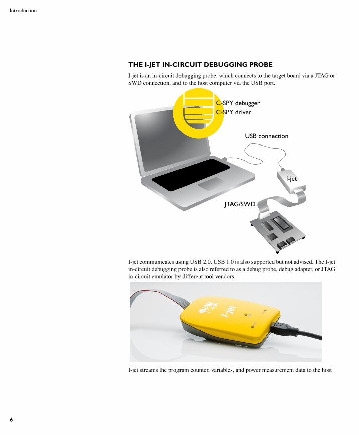
THE I-JET IN-CIRCUIT DEBUGGING PROBE
I-jet is an in-circuit debugging probe, which connects to the target board via a JTAG or SWD connection, and to the host computer via the USB port.
I-jet communicates using USB 2.0. USB 1.0 is also supported but not advised. The I-jet in-circuit debugging probe is also referred to as a debug probe, debug adapter, or JTAG in-circuit emulator by different tool vendors.
I-jet streams the program counter, variables, and power measurement data to the host
C-SPY debuggerC-SPY driver
USB connection
I-jet
JTAG/SWD
AFE1_AFE2-1:1
I-jet
7
computer to provide a view into program execution in real time. Besides the typical JTAG debugging, I-jet is capable of providing power to the target board and measuring it with sufficient accuracy to provide a power profile during program execution in real time. This feature is referred to as power debugging.
For debugging Cortex devices, I-jet also supports the SWO (Serial Wire Output) feature, which can be used for tracing the program execution and tracking variables at predefined points in your code.
REQUIREMENTS
I-jet needs to be controlled by the IAR C-SPY® Debugger which comes with the IAR Embedded Workbench® IDE.
SUPPORTED ARM CORE FAMILIES
These cores are currently supported:
● ARM7
● ARM9
● ARM11
● Cortex-M
● Cortex-R
● Cortex-A.
TARGET CONNECTIONS
These interfaces are supported:
● MIPI-20 (part number FTSH-110-01-L-DV): JTAG, SWD, SWO, ETM
● MIPI-10 (part number FTSH-105-01-L-DV): JTAG, SWD, SWO
● ARM-20 (part number HTST-110-01-L-DV): JTAG, SWD, SWO
I-jet comes with a MIPI-20 connector on the front panel and with MIPI-20 and MIPI-10 cables, as well as a legacy ARM-20 adapter.
All other available I-jet adapters are also compatible with I-jet Trace.
Working with I-jetThis section describes how to work with I-jet. More specifically, this means:
● Setup and installation
● Connecting the target system.
AFE1_AFE2-1:1
8
Working with I-jet
● Updating the probe firmware
For information about debugging using I-jet, see the C-SPY® Debugging Guide for ARM.
SETUP AND INSTALLATION
Software
Before you can use I-jet, you need to install IAR Embedded Workbench for ARM.
Probe setup
I-jet does not require any special driver software installation. Normally, all drivers for I-jet are automatically installed as part of the installation of IAR Embedded Workbench.
If you need to install the USB driver manually, navigate to \Program Files\IAR Systems\Embedded Workbench x.x\arm\drivers\jet
\USB\32-bit or 64-bit (depending on your system). Start the dpinst.exe application. This will install the USB driver.
For information about using multiple I-jet probes on the same host computer, see the C-SPY® Debugging Guide for ARM.
CONNECTING THE TARGET SYSTEM
Power-up your I-jet probe
1 Connect I-jet to the host computer using the USB micro cable.
2 Connect I-jet to the target board using the cable that matches the target board connector (MIPI-20 or MIPI-10). If a standard JTAG connector is used, you must first plug the ARM-20 to MIPI-20 adapter into the JTAG connector.
Note: No harm is done if the above order is reversed.
To prevent damage, the target GND and the USB host GND must be at the same level. When hot-plugging, make sure that the PC and the target board power supply are connected to the same grounded wall outlet or a common grounded desktop power strip.
Note: It is possible to use multiple I-jet probes on the same host computer, provided that you run multiple instances of IAR Embedded Workbench® for ARM.
Power up your evaluation board
If you have an evaluation board that is prepared for it, you can power the board via I-jet through pin 19 on the standard ARM-20 connector, or pin 11/13 on the small MIPI-20 connector. Target power of up to 420 mA can be supplied from I-jet with overload
AFE1_AFE2-1:1
I-jet
9
protection. Most of the IAR Systems KickStart Kits contain an evaluation board that can be powered this way. Make sure that the power jumper found on most of these boards matches your setup.
Note: The target board will get power via I-Jet once you choose the Download and Debug or Debug without Downloading command, but not before.
Note: The only way to use the power debugging feature is to power up your evaluation board via I-jet.
UPDATING THE PROBE FIRMWARE
I-jet and I-jet Trace are designed so that firmware updates are not necessary unless new features added to IAR Embedded Workbench for ARM require extra hardware support. When a new version of IAR Embedded Workbench for ARM is released and a new feature that requires new firmware is used, C-SPY displays a message in the Debug Log window asking you to update the firmware.
Note: Support for new MCU devices is managed totally by software updates in IAR Embedded Workbench for ARM and has nothing to do with I-jet or I-jet Trace firmware.
For more information about firmware versions, see the release notes.
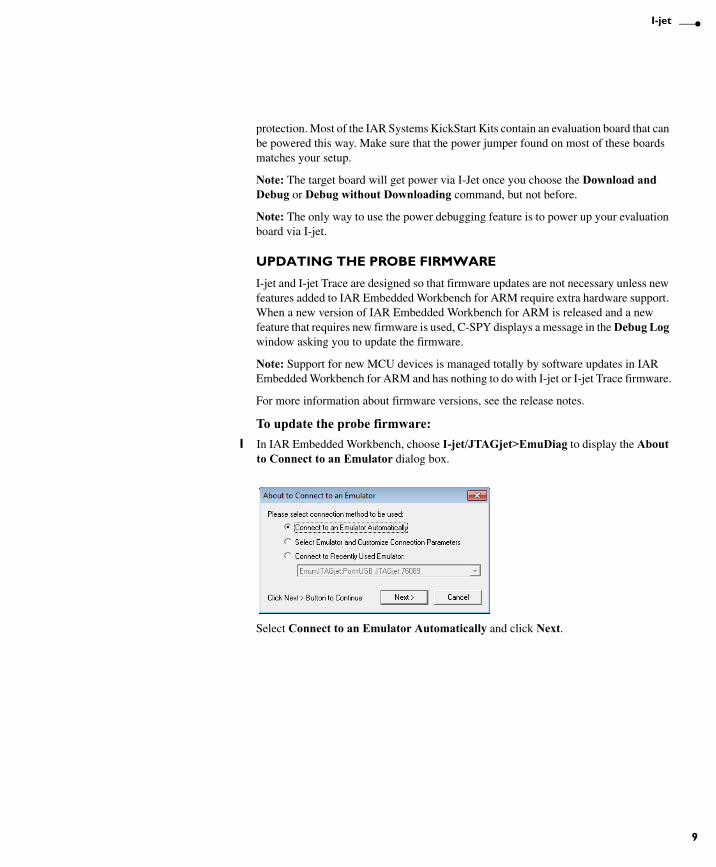
To update the probe firmware:
1 In IAR Embedded Workbench, choose I-jet/JTAGjet>EmuDiag to display the About to Connect to an Emulator dialog box.
Select Connect to an Emulator Automatically and click Next.
AFE1_AFE2-1:1
10
Working with I-jet
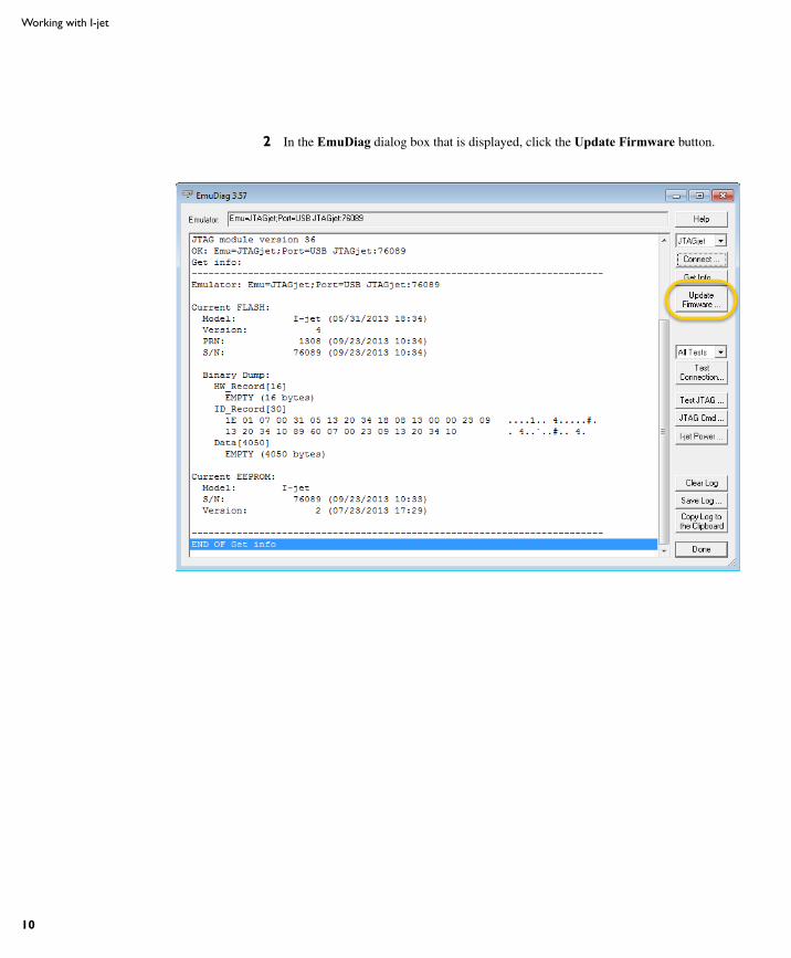
2 In the EmuDiag dialog box that is displayed, click the Update Firmware button.
AFE1_AFE2-1:1
I-jet
11
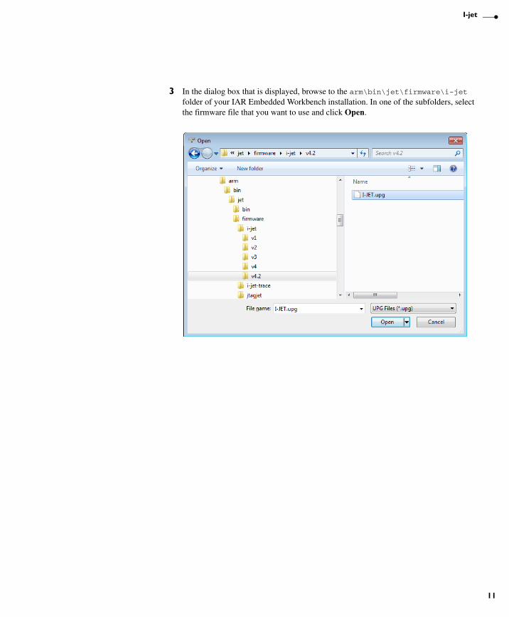
3 In the dialog box that is displayed, browse to the arm\bin\jet\firmware\i-jet folder of your IAR Embedded Workbench installation. In one of the subfolders, select the firmware file that you want to use and click Open.
AFE1_AFE2-1:1
12
Working with I-jet
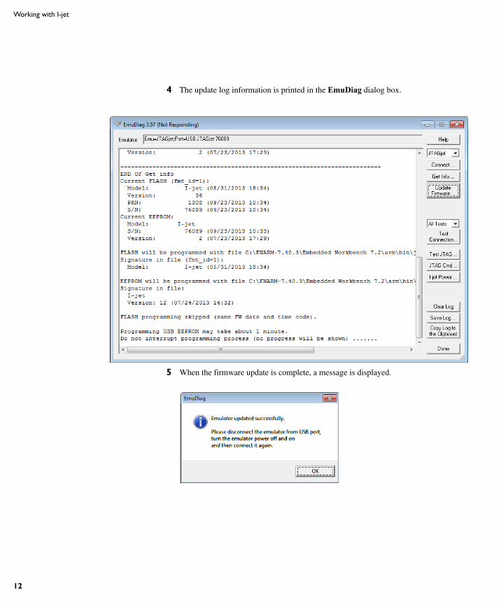
4 The update log information is printed in the EmuDiag dialog box.
5 When the firmware update is complete, a message is displayed.
AFE1_AFE2-1:1
I-jet
13
Technical specificationsThis section provides technical specifications for the I-jet in-circuit debugging probe. More specifically, this means:
● The I-jet package
● Model specifications
● JTAG timing specification
● Hardware revision history
● Target interface
● The JTAG/SWD - MIPI-20 cable
● The JTAG/SWD - MIPI-10 cable
● Indicators
● Adapters.
THE I-JET PACKAGE
The I-jet package contains:
● The I-jet in-circuit debugging probe
● MIPI-20 JTAG cable
● MIPI-10 JTAG cable
● USB-micro cable
● MIPI-20 to ARM-20 adapter
● Welcome letter.
MODEL SPECIFICATIONS
These are the specifications of I-jet:
USB speed 480 Mbps (USB 2.0)
USB connection Micro-B
Target connection MIPI-20, MIPI-10
Adapters included MIPI-20 to ARM-20
I-jet debug interface JTAG and SWD
JTAG/SWD maximum clock 32 MHz
SWO protocols supported Manchester and UART
AFE1_AFE2-1:1
14
Technical specifications
* <= 4 ns when the target board is connected
I-jet comes with a 20-pin MIPI connector (0.05 in × 0.05 in pitch) on the front panel. It includes two cables:
● A 6-inch cable with 20-pin MIPI connectors on both ends for the Cortex-M targets with 20-pin MIPI headers. Pin 7 on each end is keyed with a white plug.
● A 6-inch cable with 20-pin MIPI connectors on one side (to connect to I-jet), and 10-pin MIPI connector on the other side for connection to Cortex-M targets with 10-pin headers. Pin 7 on each end is keyed with a white plug. A red stripe on the cable indicates pin 1 (VTref).
SWO maximum speed 60 Mbps
Power supplied to target 420 mA max at 4.4 V-5 V
Over-current protection ~520 mA
Target power measurement resolution ~160 uA
Target power measurement speed up to 200 ksps (kilo samples per second)
JTAG voltage range (auto-sensing) 1.8 V to 5 V
JTAG VTref measurement resolution ~2 mV
Current draw from VTref < 50 uA
JTAG clock rise/fall time (TCK) <= 2 ns*
Clock fall time <= 2 ns*
AFE1_AFE2-1:1
I-jet
15
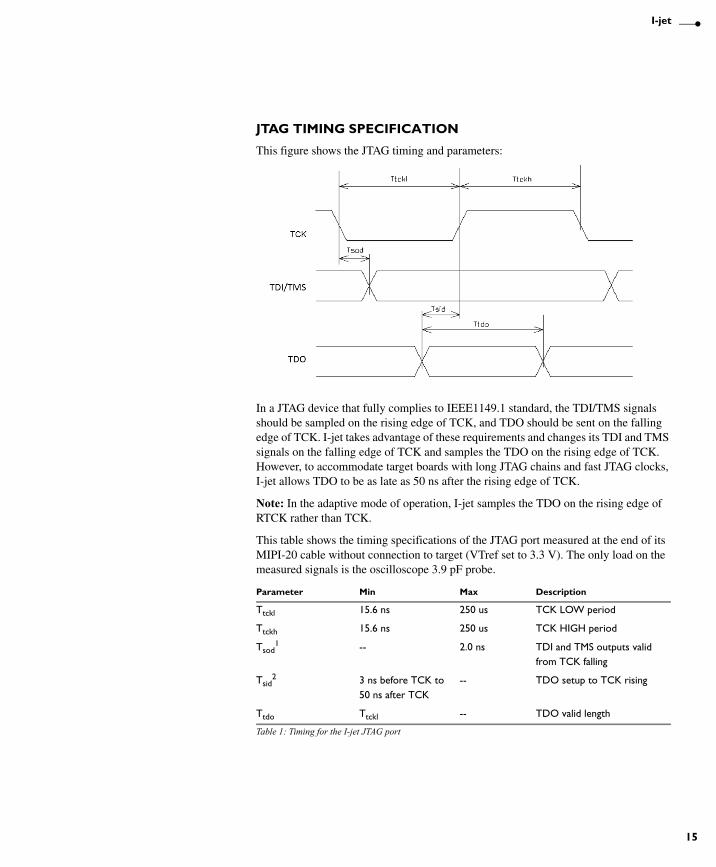
JTAG TIMING SPECIFICATION
This figure shows the JTAG timing and parameters:
In a JTAG device that fully complies to IEEE1149.1 standard, the TDI/TMS signals should be sampled on the rising edge of TCK, and TDO should be sent on the falling edge of TCK. I-jet takes advantage of these requirements and changes its TDI and TMS signals on the falling edge of TCK and samples the TDO on the rising edge of TCK. However, to accommodate target boards with long JTAG chains and fast JTAG clocks, I-jet allows TDO to be as late as 50 ns after the rising edge of TCK.
Note: In the adaptive mode of operation, I-jet samples the TDO on the rising edge of RTCK rather than TCK.
This table shows the timing specifications of the JTAG port measured at the end of its MIPI-20 cable without connection to target (VTref set to 3.3 V). The only load on the measured signals is the oscilloscope 3.9 pF probe.
Parameter Min Max Description
Ttckl 15.6 ns 250 us TCK LOW period
Ttckh 15.6 ns 250 us TCK HIGH period
Tsod1 -- 2.0 ns TDI and TMS outputs valid
from TCK falling
Tsid2 3 ns before TCK to
50 ns after TCK-- TDO setup to TCK rising
Ttdo Ttckl -- TDO valid length
Table 1: Timing for the I-jet JTAG port
AFE1_AFE2-1:1
16
Technical specifications
1 Tsod is the maximum delay from the falling edge of TCK and a valid level on the I-jet output signals TDI and TMS. The target MCU will sample these signals on the following rising edge of TCK and so the minimum setup time for the target, relative to the rising edge of TCK, is Tbscl-Tbsod.
2 Tsid is the minimum setup time for the TDO input signal, relative to the rising edge of TCK when I-jet samples this signal. Because the target MCU changes its TDO value on the previous falling edge of TCK, there might not be enough time at very-high JTAG speeds for the TDO to arrive before the positive edge of TCK. To compensate for any TDO delays, I-jet configures itself automatically to delays introduced to the TDO by the target board and will tolerate TDO delays of up to 50 ns after the positive edge of the TCK.
HARDWARE REVISION HISTORY
These are the versions of I-jet:
Version, production date, and serial number can be found on the backside of the probe.
Note: In IAR Embedded Workbench, choose I-jet/JTAGjet>EmuDiag to open the EmuDiag dialog box where you can find both hardware and firmware versions of the plugged-in I-jet.
Version Change specification Date
Version A The first version April 2012
Table 2: I-jet versions
AFE1_AFE2-1:1
I-jet
17
TARGET INTERFACE
This section contains descriptions of pinout, signals, and connectors.
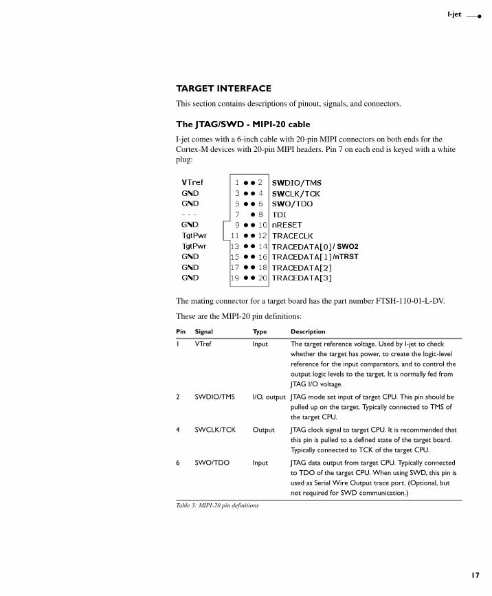
The JTAG/SWD - MIPI-20 cable
I-jet comes with a 6-inch cable with 20-pin MIPI connectors on both ends for the Cortex-M devices with 20-pin MIPI headers. Pin 7 on each end is keyed with a white plug:
The mating connector for a target board has the part number FTSH-110-01-L-DV.
These are the MIPI-20 pin definitions:
Pin Signal Type Description
1 VTref Input The target reference voltage. Used by I-jet to check whether the target has power, to create the logic-level reference for the input comparators, and to control the output logic levels to the target. It is normally fed from JTAG I/O voltage.
2 SWDIO/TMS I/O, output JTAG mode set input of target CPU. This pin should be pulled up on the target. Typically connected to TMS of the target CPU.
4 SWCLK/TCK Output JTAG clock signal to target CPU. It is recommended that this pin is pulled to a defined state of the target board. Typically connected to TCK of the target CPU.
6 SWO/TDO Input JTAG data output from target CPU. Typically connected to TDO of the target CPU. When using SWD, this pin is used as Serial Wire Output trace port. (Optional, but not required for SWD communication.)
Table 3: MIPI-20 pin definitions
/ SWO2/nTRST
AFE1_AFE2-1:1
18
Technical specifications
* Not used.
Pins 3, 5, 9, 15, 17, and 19 are GND pins connected to GND in I-jet. They should also be connected to GND in the target system.
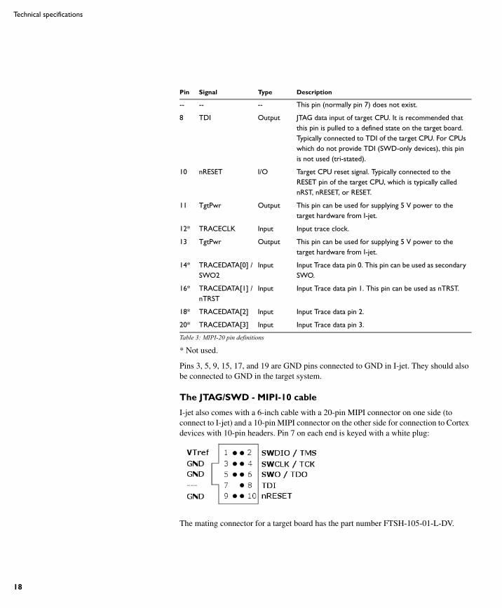
The JTAG/SWD - MIPI-10 cable
I-jet also comes with a 6-inch cable with a 20-pin MIPI connector on one side (to connect to I-jet) and a 10-pin MIPI connector on the other side for connection to Cortex devices with 10-pin headers. Pin 7 on each end is keyed with a white plug:
The mating connector for a target board has the part number FTSH-105-01-L-DV.
-- -- -- This pin (normally pin 7) does not exist.
8 TDI Output JTAG data input of target CPU. It is recommended that this pin is pulled to a defined state on the target board. Typically connected to TDI of the target CPU. For CPUs which do not provide TDI (SWD-only devices), this pin is not used (tri-stated).
10 nRESET I/O Target CPU reset signal. Typically connected to the RESET pin of the target CPU, which is typically called nRST, nRESET, or RESET.
11 TgtPwr Output This pin can be used for supplying 5 V power to the target hardware from I-jet.
12* TRACECLK Input Input trace clock.
13 TgtPwr Output This pin can be used for supplying 5 V power to the target hardware from I-jet.
14* TRACEDATA[0] /SWO2
Input Input Trace data pin 0. This pin can be used as secondary SWO.
16* TRACEDATA[1] /nTRST
Input Input Trace data pin 1. This pin can be used as nTRST.
18* TRACEDATA[2] Input Input Trace data pin 2.
20* TRACEDATA[3] Input Input Trace data pin 3.
Pin Signal Type Description
Table 3: MIPI-20 pin definitions
AFE1_AFE2-1:1
I-jet
19
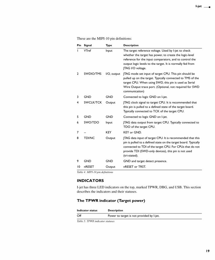
These are the MIPI-10 pin definitions:
INDICATORS
I-jet has three LED indicators on the top, marked TPWR, DBG, and USB. This section describes the indicators and their statuses.
The TPWR indicator (Target power)
Pin Signal Type Description
1 VTref Input The target reference voltage. Used by I-jet to check whether the target has power, to create the logic-level reference for the input comparators, and to control the output logic levels to the target. It is normally fed from JTAG I/O voltage.
2 SWDIO/TMS I/O, output JTAG mode set input of target CPU. This pin should be pulled up on the target. Typically connected to TMS of the target CPU. When using SWD, this pin is used as Serial Wire Output trace port. (Optional, not required for SWD communication)
3 GND GND Connected to logic GND on I-jet.
4 SWCLK/TCK Output JTAG clock signal to target CPU. It is recommended that this pin is pulled to a defined state of the target board. Typically connected to TCK of the target CPU.
5 GND GND Connected to logic GND on I-jet.
6 SWO/TDO Input JTAG data output from target CPU. Typically connected to TDO of the target CPU.
7 -- KEY KEY or GND.
8 TDI/NC Output JTAG data input of target CPU. It is recommended that this pin is pulled to a defined state on the target board. Typically connected to TDI of the target CPU. For CPUs that do not provide TDI (SWD-only devices), this pin is not used (tri-stated).
9 GND GND GND and target detect presence.
10 nRESET Output nRESET or TRST.
Table 4: MIPI-10 pin definitions
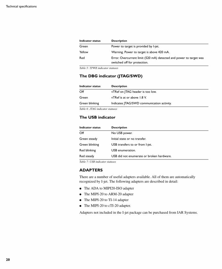
Indicator status Description
Off Power to target is not provided by I-jet.
Table 5: TPWR indicator statuses
AFE1_AFE2-1:1
20
Technical specifications
The DBG indicator (JTAG/SWD)
The USB indicator
ADAPTERS
There are a number of useful adapters available. All of them are automatically recognized by I-jet. The following adapters are described in detail:
● The ADA to MIPI20-ISO adapter
● The MIPI-20 to ARM-20 adapter
● The MIPI-20 to TI-14 adapter
● The MIPI-20 to cTI-20 adapter.
Adapters not included in the I-jet package can be purchased from IAR Systems.
Green Power to target is provided by I-jet.
Yellow Warning. Power to target is above 420 mA.
Red Error. Overcurrent limit (520 mA) detected and power to target was switched off for protection.
Indicator status Description
Off vTRef on JTAG header is too low.
Green vTRef is at or above 1.8 V.
Green blinking Indicates JTAG/SWD communication activity.
Table 6: JTAG indicator statuses
Indicator status Description
Off No USB power.
Green steady Initial state or no transfer.
Green blinking USB transfers to or from I-jet.
Red blinking USB enumeration.
Red steady USB did not enumerate or broken hardware.
Table 7: USB indicator statuses
Indicator status Description
Table 5: TPWR indicator statuses
AFE1_AFE2-1:1
I-jet
21
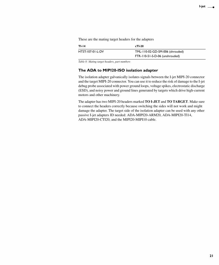
These are the mating target headers for the adapters
The ADA to MIPI20-ISO isolation adapter
The isolation adapter galvanically isolates signals between the I-jet MIPI-20 connector and the target MIPI-20 connector. You can use it to reduce the risk of damage to the I-jet debug probe associated with power ground loops, voltage spikes, electrostatic discharge (ESD), and noisy power and ground lines generated by targets which drive high-current motors and other machinery.
The adapter has two MIPI-20 headers marked TO I-JET and TO TARGET. Make sure to connect the headers correctly because switching the sides will not work and might damage the adapter. The target side of the isolation adapter can be used with any other passive I-jet adapters ID needed: ADA-MIPI20-ARM20, ADA-MIPI20-TI14, ADA-MIPI20-CTI20, and the MIPI20-MIPI10 cable.
TI-14 cTI-20
HTST-107-01-L-DV TML-110-02-GD-SM-006 (shrouded)FTR-110-51-S-D-06 (unshrouded)
Table 8: Mating target headers, part numbers
AFE1_AFE2-1:1
22
Technical specifications
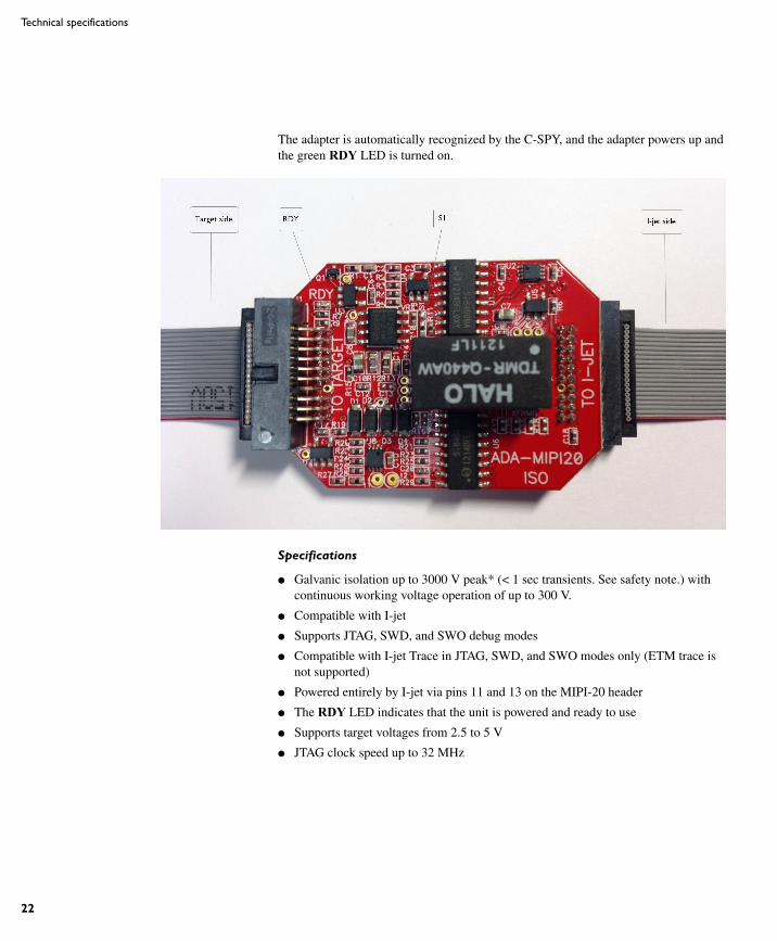
The adapter is automatically recognized by the C-SPY, and the adapter powers up and the green RDY LED is turned on.
Specifications
● Galvanic isolation up to 3000 V peak* (< 1 sec transients. See safety note.) with continuous working voltage operation of up to 300 V.
● Compatible with I-jet
● Supports JTAG, SWD, and SWO debug modes
● Compatible with I-jet Trace in JTAG, SWD, and SWO modes only (ETM trace is not supported)
● Powered entirely by I-jet via pins 11 and 13 on the MIPI-20 header
● The RDY LED indicates that the unit is powered and ready to use
● Supports target voltages from 2.5 to 5 V
● JTAG clock speed up to 32 MHz
AFE1_AFE2-1:1
I-jet
23
Compatibility notes
● The adapter might not be automatically detected and powered by older versions of IAR Embedded Workbench for ARM. In such cases, select the Target Power option on the Project>Options>Debugger>I-jet/JTAGjet>Setup page.
● The adapter does not supply power to target and therefore does not resume the target power consumption.
● When used with the TI14 and CTI20 adapters, the EMU0 and EMU1 signals are not connected.
● Due to added JTAG signals propagation delays, some target boards might not work at the full 32 MHz JTAG clock speed, so reducing the JTAG speed in C-SPY might be needed.
● The majority of target boards have the SWO signal routed to pin 6 of the target MIPI20 debug connector. In cases when pin 14 is used for SWO, you must move the 0R shunt (marked S1) up from position 3-2 to position 2-1.
● The adapter does not support 1.8 V JTAG signals from target. The target JTAG voltage range is limited to 2.5-5 V.
● The JTAG interface on the target side automatically adapts to the voltage given on the target VTREF pin (2.5 V-5 V). Because of the isolation barrier, the I-jet side uses its own voltage, independent of the target voltage. This is for information only and has no effect on the target JTAG operation.
● ETM trace is not supported by this adapter.
● This adapter cannot be used with I-scope.
AFE1_AFE2-1:1
24
Technical specifications
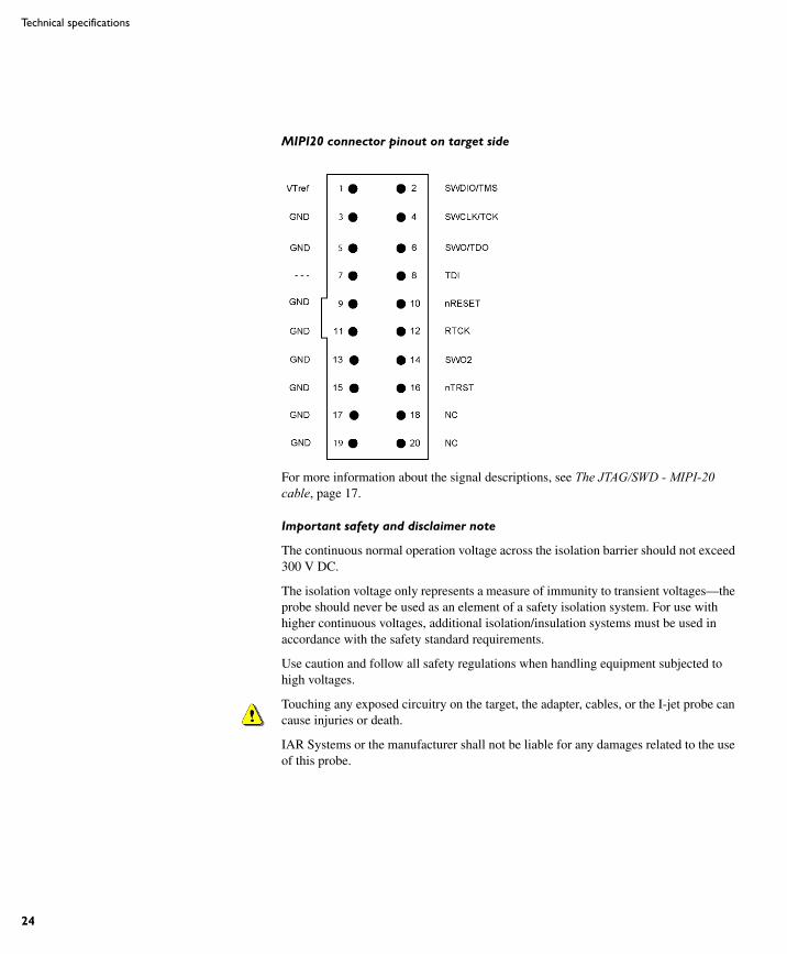
MIPI20 connector pinout on target side
For more information about the signal descriptions, see The JTAG/SWD - MIPI-20 cable, page 17.
Important safety and disclaimer note
The continuous normal operation voltage across the isolation barrier should not exceed 300 V DC.
The isolation voltage only represents a measure of immunity to transient voltages—the probe should never be used as an element of a safety isolation system. For use with higher continuous voltages, additional isolation/insulation systems must be used in accordance with the safety standard requirements.
Use caution and follow all safety regulations when handling equipment subjected to high voltages.
Touching any exposed circuitry on the target, the adapter, cables, or the I-jet probe can cause injuries or death.
IAR Systems or the manufacturer shall not be liable for any damages related to the use of this probe.
AFE1_AFE2-1:1
I-jet
25
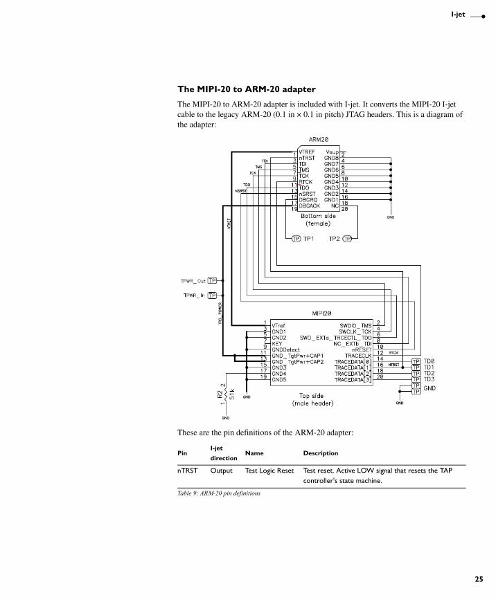
The MIPI-20 to ARM-20 adapter
The MIPI-20 to ARM-20 adapter is included with I-jet. It converts the MIPI-20 I-jet cable to the legacy ARM-20 (0.1 in × 0.1 in pitch) JTAG headers. This is a diagram of the adapter:
These are the pin definitions of the ARM-20 adapter:
PinI-jet
directionName Description
nTRST Output Test Logic Reset Test reset. Active LOW signal that resets the TAP controller's state machine.
Table 9: ARM-20 pin definitions
AFE1_AFE2-1:1
26
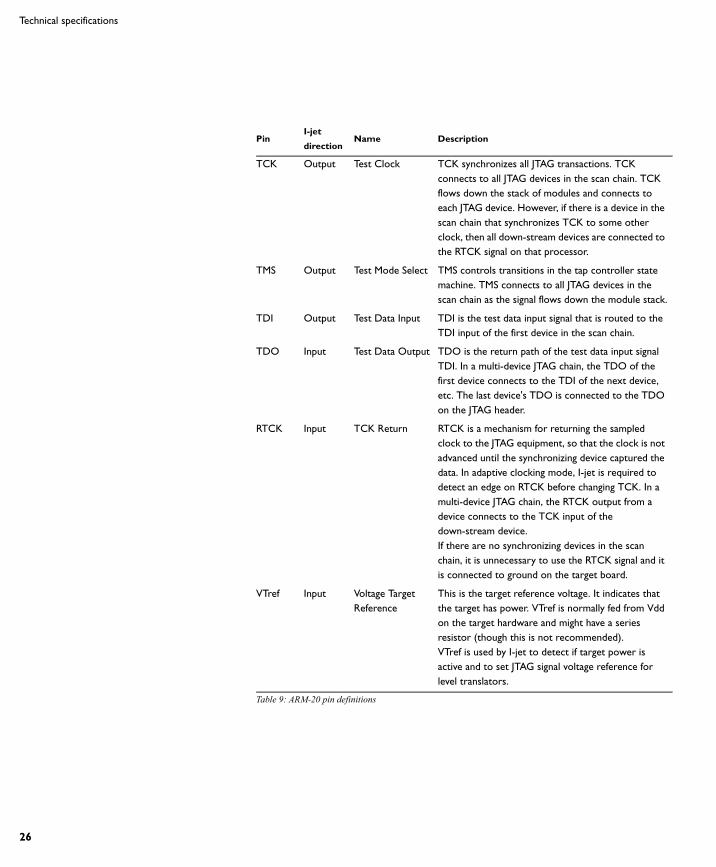
Technical specifications
TCK Output Test Clock TCK synchronizes all JTAG transactions. TCK connects to all JTAG devices in the scan chain. TCK flows down the stack of modules and connects to each JTAG device. However, if there is a device in the scan chain that synchronizes TCK to some other clock, then all down-stream devices are connected to the RTCK signal on that processor.
TMS Output Test Mode Select TMS controls transitions in the tap controller state machine. TMS connects to all JTAG devices in the scan chain as the signal flows down the module stack.
TDI Output Test Data Input TDI is the test data input signal that is routed to the TDI input of the first device in the scan chain.
TDO Input Test Data Output TDO is the return path of the test data input signal TDI. In a multi-device JTAG chain, the TDO of the first device connects to the TDI of the next device, etc. The last device's TDO is connected to the TDO on the JTAG header.
RTCK Input TCK Return RTCK is a mechanism for returning the sampled clock to the JTAG equipment, so that the clock is not advanced until the synchronizing device captured the data. In adaptive clocking mode, I-jet is required to detect an edge on RTCK before changing TCK. In a multi-device JTAG chain, the RTCK output from a device connects to the TCK input of the down-stream device.If there are no synchronizing devices in the scan chain, it is unnecessary to use the RTCK signal and it is connected to ground on the target board.
VTref Input Voltage Target Reference
This is the target reference voltage. It indicates that the target has power. VTref is normally fed from Vdd on the target hardware and might have a series resistor (though this is not recommended).VTref is used by I-jet to detect if target power is active and to set JTAG signal voltage reference for level translators.
PinI-jet
directionName Description
Table 9: ARM-20 pin definitions
AFE1_AFE2-1:1
I-jet
27
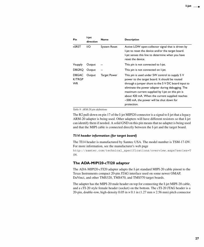
The R2 pull-down on pin 17 of the I-jet MIPI20 connector is a signal to I-jet that a legacy ARM-20 adapter is being used. Other adapters will have different resistors so that I-jet can identify them if needed. A solid GND on this pin means that no adapter is being used and that the MIPI cable is connected directly between the I-jet and the target board.
TI14 header information (for target board)
The TI14 header is manufactured by Samtec USA. The model number is TSM-17-DV. For more information, see the manufacturer's web page http://samtec.com/technical_specifications/overview.aspx?series=T
SM.
The ADA-MIPI20-cTI20 adapter
The ADA-MIPI20-cTI20 adapter adapts the I-jet standard MIPI-20 cable pinout to the Texas Instruments compact 20-pin JTAG interface used on some newer OMAP, DaVinci, and other TMS320, TMS470, and TMS570 target boards.
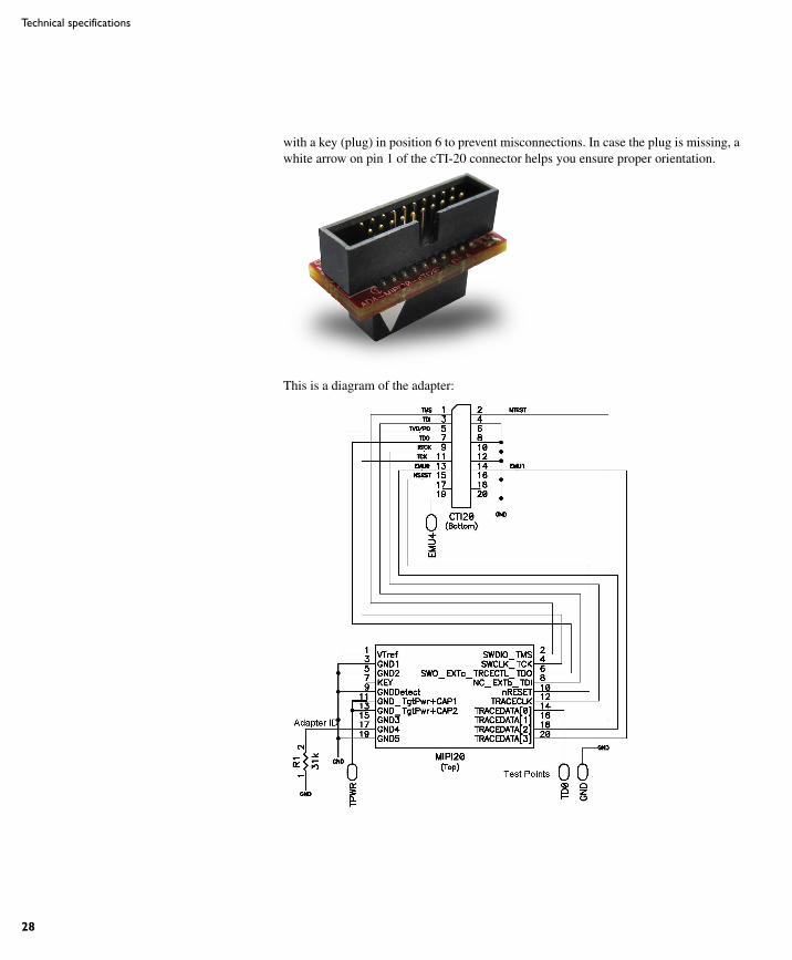
The adapter has the MIPI-20 male header on top for connecting the I-jet MIPI-20 cable, and a cTI-20 style female header (socket) on the bottom. The cTI-20 JTAG header is a 20-pin, double-row, high-density 0.05 in × 0.1 in (1.27 mm × 2.56 mm) pitch connector
nSRST I/O System Reset Active LOW open-collector signal that is driven by I-jet to reset the device and/or the target board.I-jet senses this line to determine when you have reset the device.
Vsupply Output -- This pin is not connected to I-jet.
DBGRQ Output -- This pin is not connected on I-jet.
DBGACK/TRGPWR
Output Target Power This pin is used under SW control to supply 5 V power to the target board. It should be routed through a jumper shunt to the 5 V DC board input to eliminate the power adapter during debugging. The maximum current supplied by I-jet on this pin is about 420 mA. When the current supplied reaches ~500 mA, the power will be shut down for protection.
PinI-jet
directionName Description
Table 9: ARM-20 pin definitions
AFE1_AFE2-1:1
28
Technical specifications
with a key (plug) in position 6 to prevent misconnections. In case the plug is missing, a white arrow on pin 1 of the cTI-20 connector helps you ensure proper orientation.
This is a diagram of the adapter:
AFE1_AFE2-1:1
I-jet
29
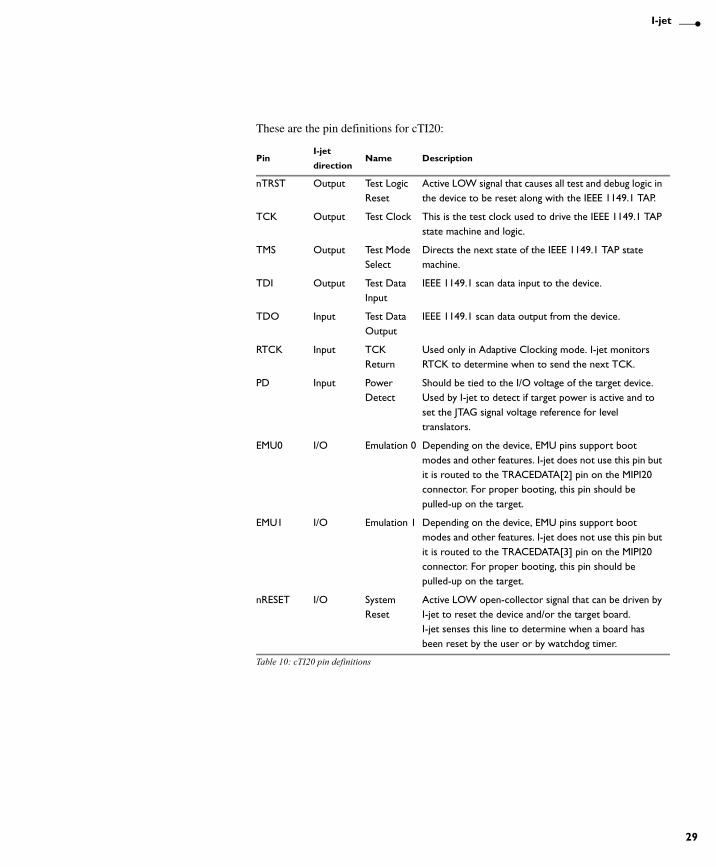
These are the pin definitions for cTI20:
PinI-jet
directionName Description
nTRST Output Test Logic Reset
Active LOW signal that causes all test and debug logic in the device to be reset along with the IEEE 1149.1 TAP.
TCK Output Test Clock This is the test clock used to drive the IEEE 1149.1 TAP state machine and logic.
TMS Output Test Mode Select
Directs the next state of the IEEE 1149.1 TAP state machine.
TDI Output Test Data Input
IEEE 1149.1 scan data input to the device.
TDO Input Test Data Output
IEEE 1149.1 scan data output from the device.
RTCK Input TCK Return
Used only in Adaptive Clocking mode. I-jet monitors RTCK to determine when to send the next TCK.
PD Input Power Detect
Should be tied to the I/O voltage of the target device. Used by I-jet to detect if target power is active and to set the JTAG signal voltage reference for level translators.
EMU0 I/O Emulation 0 Depending on the device, EMU pins support boot modes and other features. I-jet does not use this pin but it is routed to the TRACEDATA[2] pin on the MIPI20 connector. For proper booting, this pin should be pulled-up on the target.
EMU1 I/O Emulation 1 Depending on the device, EMU pins support boot modes and other features. I-jet does not use this pin but it is routed to the TRACEDATA[3] pin on the MIPI20 connector. For proper booting, this pin should be pulled-up on the target.
nRESET I/O System Reset
Active LOW open-collector signal that can be driven by I-jet to reset the device and/or the target board.I-jet senses this line to determine when a board has been reset by the user or by watchdog timer.
Table 10: cTI20 pin definitions

AFE1_AFE2-1:1
30
Technical specifications
This is the pinout of the target cTI20 JTAG header. Pin 6 should be missing to indicate the proper orientation.
These are the top view dimensions of the ADA-MIPI20-cTI20 adapter:
These are the side view dimensions of the ADA-MIPI20-cTI20 adapter:
A 18.9 mm (0.74 in)
B 17.7 mm (0.7 in)
C 19.4 mm (0.76 in)
D 1.8 mm (0.07 in)
J 6.0 mm (0.24 in)
K 12.8 mm (0.50 in)
G 0.5 mm (0.19 in)
H 5.1 mm (0.2 in)
TMS
TDI
TVD (PD)
TDO
TCKRTN
TCK
EMU0
nSYSRST
EMU2 (NC)
EMU4 (NC)
nTRST
TDIS
KEY
GND
GND
GND
EMU1
GND
EMU3 (NC)
GND
1 2
3 4
5 6
7 8
9 10
11 12
13 14
15 16
17 18
19 20

AFE1_AFE2-1:1
I-jet
31
cTI20 header information (for target board)
The cTI20 header is manufactured by Samtec USA. The model number is FTR-110-51-S-D-06. For more information, see the manufacturer's web page http://www.samtec.com/technical_specifications/overview.aspx?seri
es=FTR.
I 9.1 mm (0.36 in)

AFE1_AFE2-1:1
32
Technical specifications
AFE1_AFE2-1:1
33
I-jet TraceThis chapter describes the I-jet Trace for Cortex-M in-circuit debugging probe. More specifically, this means:
● Introduction
● Working with I-jet Trace
● Technical specifications
IntroductionThis section gives a short overview of the I-jet Trace in-circuit debugging probe. More specifically, this means:
● The I-jet Trace in-circuit debugging probe
● Requirements
● Target connections.
AFE1_AFE2-1:1
34
Introduction
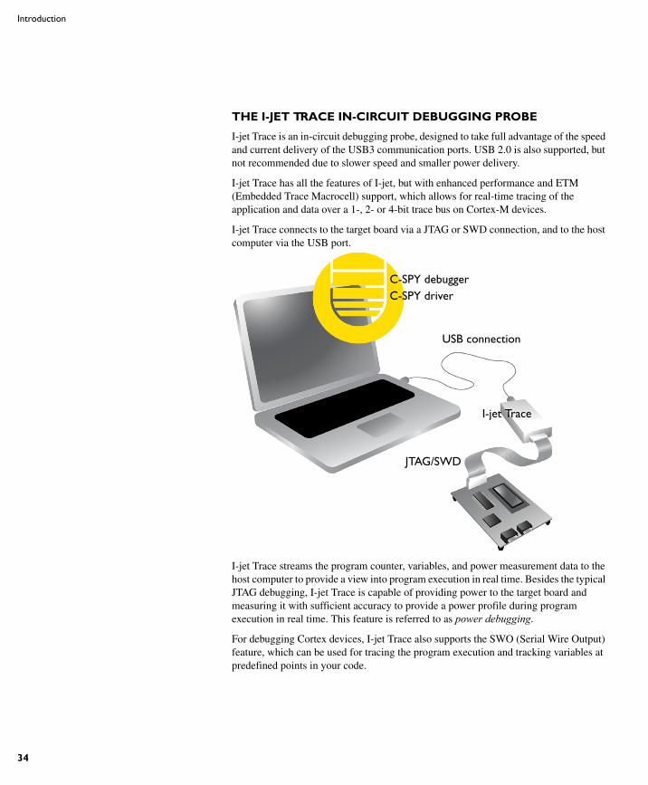
THE I-JET TRACE IN-CIRCUIT DEBUGGING PROBE
I-jet Trace is an in-circuit debugging probe, designed to take full advantage of the speed and current delivery of the USB3 communication ports. USB 2.0 is also supported, but not recommended due to slower speed and smaller power delivery.
I-jet Trace has all the features of I-jet, but with enhanced performance and ETM (Embedded Trace Macrocell) support, which allows for real-time tracing of the application and data over a 1-, 2- or 4-bit trace bus on Cortex-M devices.
I-jet Trace connects to the target board via a JTAG or SWD connection, and to the host computer via the USB port.
I-jet Trace streams the program counter, variables, and power measurement data to the host computer to provide a view into program execution in real time. Besides the typical JTAG debugging, I-jet Trace is capable of providing power to the target board and measuring it with sufficient accuracy to provide a power profile during program execution in real time. This feature is referred to as power debugging.
For debugging Cortex devices, I-jet Trace also supports the SWO (Serial Wire Output) feature, which can be used for tracing the program execution and tracking variables at predefined points in your code.
C-SPY debuggerC-SPY driver
USB connection
I-jet Trace
JTAG/SWD
AFE1_AFE2-1:1
I-jet Trace
35
The I-jet Trace in-circuit debugging probe is also referred to as a debug probe, debug adapter, or JTAG in-circuit emulator by different tool vendors.
REQUIREMENTS
I-jet Trace needs to be controlled by the IAR C-SPY® Debugger which comes with the IAR Embedded Workbench® IDE.
TARGET CONNECTIONS
These interfaces are supported:
● MIPI-20 (part number FTSH-110-01-L-DV): JTAG, SWD, SWO, ETM
● MIPI-10 (part number FTSH-105-01-L-DV): JTAG, SWD, SWO
● ARM-20 (part number HTST-110-01-L-DV): JTAG, SWD, SWO
I-jet Trace comes with a MIPI-20 connector on the front panel and with MIPI-20 and MIPI-10 cables, as well as a legacy ARM-20 adapter.
Note: Only the MIPI-20 cable supports the ETM trace functionality. All other connections (MIPI-10 and ARM-20) are only for plain JTAG/SWD/SWO debugging.
All other available I-jet adapters are also compatible with I-jet Trace.
Working with I-jet TraceThis section describes how to work with I-jet Trace. More specifically, this means:
● Setup and installation
● Connecting the target system
● Using trace
● Updating the probe firmware
For information about debugging using I-jet Trace, see the C-SPY® Debugging Guide for ARM.
SETUP AND INSTALLATION
Software
Before you can use I-jet Trace, you need to install IAR Embedded Workbench for ARM. For more information, see the Quick Reference Installation and Licensing guide.
AFE1_AFE2-1:1
36
Working with I-jet Trace
Probe setup
I-jet Trace does not require any special driver software installation. Normally, all drivers for I-jet Trace are automatically installed as part of the installation of IAR Embedded Workbench.
If you need to install the USB driver manually, navigate to \Program Files\IAR Systems\Embedded Workbench x.x\arm\drivers\jet
\USB3\32-bit or 64-bit (depending on your system). Start the dpinst.exe application. This will install the USB driver.
The USB LED will flash twice after enumerating on the USB2 ports, and three times on USB3 ports.
For information about using multiple I-jet probes on the same host computer, see the C-SPY® Debugging Guide for ARM.
CONNECTING THE TARGET SYSTEM
Power-up your I-jet Trace probe
1 Connect I-jet Trace to the host computer using the USB micro cable.
2 Connect I-jet Trace to the target board using the cable that matches the target board connector (MIPI-20 or MIPI-10). If a standard JTAG connector is used, you must first plug the ARM-20 to MIPI-20 adapter into the JTAG connector.
Note: No harm is done if the above order is reversed.
To prevent damage, the target GND and the USB host GND must be at the same level. When hot-plugging, make sure that the PC and the target board power supply are connected to the same grounded wall outlet or a common grounded desktop power strip.
Note: It is possible to use multiple I-jet probes on the same host computer, provided that you run multiple instances of IAR Embedded Workbench® for ARM.
Power up your evaluation board
If you have an evaluation board that is prepared for it, you can power the board via I-jet Trace through pin 19 on the standard ARM-20 connector, or pin 11/13 on the small MIPI-20 connector. Target power of up to 420 mA can be supplied from I-jet Trace with overload protection. Most of the IAR Systems KickStart Kits contain an evaluation board that can be powered this way. Make sure that the power jumper found on most of these boards matches your setup.
Note: The target board will get power via I-Jet Trace once you choose the Download and Debug or Debug without Downloading command in C-SPY, but not before.
AFE1_AFE2-1:1
I-jet Trace
37
Note: The only way to use the power debugging feature is to power up your evaluation board via I-jet Trace.
USING TRACE
To use ETM trace, the target board must have a Cortex-M device with the ETM trace pins (usually named TraceCLK and TraceD0-D3), and these pins must be connected to the MIPI-20 debug header. Because on some devices, the trace pins are multiplexed, take care not to connect these pins to other logic devices on the PCB to minimize the loading and improve signal integrity.
C-SPY will initialize and enable all necessary registers on the MCU to allow the ETM port to function properly so that no special user code instrumentation is necessary. However, take care so that the running application code does not interfere (read, write, etc.) with the GPIO pins used for the ETM trace.
The TRACE LED on the I-jet Trace debug probe will turn green when the trace data collection is ready for ETM data. This usually happens after trace is enabled in C-SPY and the Run command is issued.
For more information about trace, see the C-SPY Debugging Guide.
UPDATING THE PROBE FIRMWARE
For more information, see Updating the probe firmware, page 9.
Technical specificationsThis section provides technical specifications for the I-jet Trace in-circuit debugging probe. More specifically, this means:
● The I-jet Trace package
● Model specifications
● Connectors
THE I-JET TRACE PACKAGE
The I-jet Trace package contains:
● The I-jet Trace in-circuit debugging probe
● MIPI-20 JTAG cable
● MIPI-10 JTAG cable
● USB3 A to micro-B cable
● MIPI-20 to ARM-20 adapter
AFE1_AFE2-1:1
38
Technical specifications
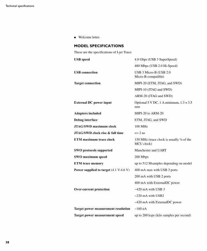
● Welcome letter.
MODEL SPECIFICATIONS
These are the specifications of I-jet Trace:
USB speed 4.8 Gbps (USB 3 SuperSpeed)
480 Mbps (USB 2.0 Hi-Speed)
USB connection USB 3 Micro-B (USB 2.0 Micro-B-compatible)
Target connection MIPI-20 (ETM, JTAG, and SWD)
MIPI-10 (JTAG and SWD)
ARM-20 (JTAG and SWD)
External DC power input Optional 5 V DC, 1 A minimum, 1.3 × 3.5 mm
Adapters included MIPI-20 to ARM-20
Debug interface ETM, JTAG, and SWD
JTAG/SWD maximum clock 100 MHz
JTAG/SWD clock rise & fall time <= 2 ns
ETM maximum trace clock 150 MHz (trace clock is usually ½ of the MCU clock)
SWO protocols supported Manchester and UART
SWO maximum speed 200 Mbps
ETM trace memory up to 512 Msamples depending on model
Power supplied to target (4.1 V-4.6 V) 400 mA max with USB 3 ports
200 mA with USB 2 ports
400 mA with ExternalDC power
Over-current protection ~420 mA with USB 3
~220 mA with USB2
~420 mA with ExternalDC power
Target power measurement resolution ~160 uA
Target power measurement speed up to 200 ksps (kilo samples per second)
AFE1_AFE2-1:1
I-jet Trace
39
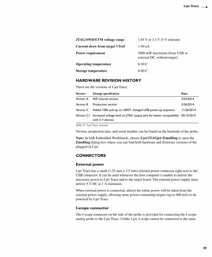
HARDWARE REVISION HISTORY
These are the versions of I-jet Trace:
Version, production date, and serial number can be found on the backside of the probe.
Note: In IAR Embedded Workbench, choose I-jet/JTAGjet>EmuDiag to open the EmuDiag dialog box where you can find both hardware and firmware versions of the plugged-in I-jet.
CONNECTORS
External power
I-jet Trace has a small (1.35 mm × 3.5 mm) external power connector right next to the USB connector. It can be used whenever the host computer is unable to deliver the necessary power to I-jet Trace and to the target board. The external power supply must deliver 5 V DC at 1 A minimum.
When external power is connected, almost the entire power will be taken from the external power supply, allowing more power-consuming targets (up to 400 mA) to be powered by I-jet Trace.
I-scope connector
The I-scope connector on the side of the probe is provided for connecting the I-scope analog probe to the I-jet Trace. Unlike I-jet, I-scope cannot be connected to the same
JTAG/SWD/ETM voltage range 1.65 V to 3.3 V (5 V tolerant)
Current draw from target VTref < 50 uA
Power requirement 3000 mW maximum (from USB or external DC, without target)
Operating temperature 0-30 C
Storage temperature 0-80 C
Version Change specification Date
Version A IAR internal version 3/24/2014
Version B Production version 5/26/2014
Version C Added 100k pull-up on nSRST, changed USB power-up sequence 11/26/2014
Version C1 Increased voltage level on JTAG output pins for better compatibility with 5 V devices
05/15/2015
Table 11: I-jet Trace versions
AFE1_AFE2-1:1
40
Technical specifications
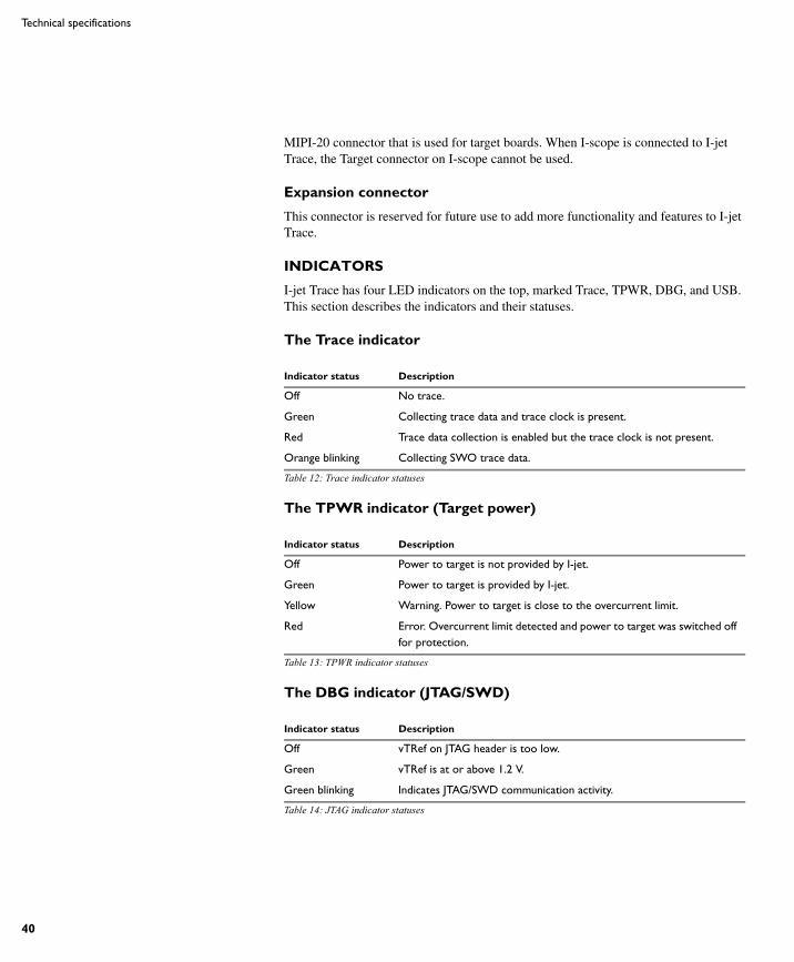
MIPI-20 connector that is used for target boards. When I-scope is connected to I-jet Trace, the Target connector on I-scope cannot be used.
Expansion connector
This connector is reserved for future use to add more functionality and features to I-jet Trace.
INDICATORS
I-jet Trace has four LED indicators on the top, marked Trace, TPWR, DBG, and USB. This section describes the indicators and their statuses.
The Trace indicator
The TPWR indicator (Target power)
The DBG indicator (JTAG/SWD)
Indicator status Description
Off No trace.
Green Collecting trace data and trace clock is present.
Red Trace data collection is enabled but the trace clock is not present.
Orange blinking Collecting SWO trace data.
Table 12: Trace indicator statuses
Indicator status Description
Off Power to target is not provided by I-jet.
Green Power to target is provided by I-jet.
Yellow Warning. Power to target is close to the overcurrent limit.
Red Error. Overcurrent limit detected and power to target was switched off for protection.
Table 13: TPWR indicator statuses
Indicator status Description
Off vTRef on JTAG header is too low.
Green vTRef is at or above 1.2 V.
Green blinking Indicates JTAG/SWD communication activity.
Table 14: JTAG indicator statuses
AFE1_AFE2-1:1
I-jet Trace
41
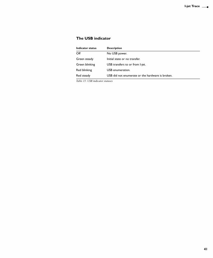
The USB indicator
Indicator status Description
Off No USB power.
Green steady Initial state or no transfer.
Green blinking USB transfers to or from I-jet.
Red blinking USB enumeration.
Red steady USB did not enumerate or the hardware is broken.
Table 15: USB indicator statuses

AFE1_AFE2-1:1
42
Technical specifications
AFE1_AFE2-1:1
43
I-scopeThis chapter describes the I-scope power probe for I-jet/I-jet Trace. More specifically, this means:
● Introduction
● Working with I-scope
● Technical specifications
IntroductionThis section gives a short overview of the I-scope power probe for I-jet/I-jet Trace. More specifically, this means:
● Reasons for using I-scope
● The I-scope probe
● Current and voltage measurement using I-scope.
REASONS FOR USING I-SCOPE
The main benefit of using I-scope is to provide you with power data of the running application in real time so you can view the power profile and optimize your code for better power efficiency. The C-SPY Timeline window displays power data in correlation with the application source code to enable power analysis of the program flow.
The analysis will reveal which functions and peripheral units consume more power, which I/O activity causes current spikes, how much power the MCU consumes in various sleep modes or in the main idle loop, etc. The captured data can be used to help you make your design less power-consuming, as well as help you initialize the GPIOs and peripheral units to achieve the best power efficiency without compromising the target's performance.
THE I-SCOPE PROBE
IAR I-scope for I-jet/I-jet Trace plugs in between the I-jet/I-jet Trace in-circuit debugging probe and the target board. I-scope adds detailed current and voltage measurement capability to I-jet/I-jet Trace. These measurements can be done at any designated points on the target board and displayed in real time by the IAR C-SPY debugger.
AFE1_AFE2-1:1
44
Introduction
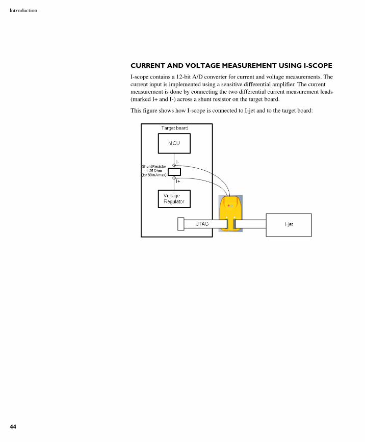
CURRENT AND VOLTAGE MEASUREMENT USING I-SCOPE
I-scope contains a 12-bit A/D converter for current and voltage measurements. The current input is implemented using a sensitive differential amplifier. The current measurement is done by connecting the two differential current measurement leads (marked I+ and I-) across a shunt resistor on the target board.
This figure shows how I-scope is connected to I-jet and to the target board:
AFE1_AFE2-1:1
I-scope
45
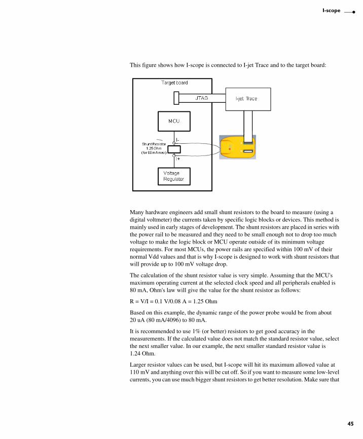
This figure shows how I-scope is connected to I-jet Trace and to the target board:
Many hardware engineers add small shunt resistors to the board to measure (using a digital voltmeter) the currents taken by specific logic blocks or devices. This method is mainly used in early stages of development. The shunt resistors are placed in series with the power rail to be measured and they need to be small enough not to drop too much voltage to make the logic block or MCU operate outside of its minimum voltage requirements. For most MCUs, the power rails are specified within 100 mV of their normal Vdd values and that is why I-scope is designed to work with shunt resistors that will provide up to 100 mV voltage drop.
The calculation of the shunt resistor value is very simple. Assuming that the MCU's maximum operating current at the selected clock speed and all peripherals enabled is 80 mA, Ohm's law will give the value for the shunt resistor as follows:
R = V/I = 0.1 V/0.08 A = 1.25 Ohm
Based on this example, the dynamic range of the power probe would be from about 20 uA (80 mA/4096) to 80 mA.
It is recommended to use 1% (or better) resistors to get good accuracy in the measurements. If the calculated value does not match the standard resistor value, select the next smaller value. In our example, the next smaller standard resistor value is 1.24 Ohm.
Larger resistor values can be used, but I-scope will hit its maximum allowed value at 110 mV and anything over this will be cut off. So if you want to measure some low-level currents, you can use much bigger shunt resistors to get better resolution. Make sure that
AFE1_AFE2-1:1
46
Working with I-scope
the MCU Vdd line does not drop below the minimum allowed by the manufacturer when the MCU goes into the high-current mode. For information about the minimum value for your specific processor, see its data sheet.
To convert the current measurements to the actual power consumed by the MCU, I-scope automatically measures voltage at the I- terminal of the shunt resistor.
I-scope measures current and voltages at a sampling rate of up to 200 kHz and sends it to I-jet/I-jet Trace which synchronizes it with the running MCU's program counter (if available), so it can be displayed in real time and analyzed using C-SPY.
For more information about power debugging using C-SPY, see the C-SPY Debugging Guide.
Working with I-scopeThis section describes how to work with I-scope.
INSTALLATION
1 Connect I-scope to I-jet/I-jet Trace using the supplied MIPI-20 cable.
2 Connect the target to I-scope using the MIPI-20 cable that came with I-jet/I-jet Trace.
3 Start IAR Embedded Workbench and select your project.
4 To measure current, connect the I+ and I- leads across the shunt resistor on your board. The I+ lead should be connected on the higher voltage side, which is the one coming from the voltage regulator or power supply. If the leads are reversed, the Power graph in the Timeline window will show current and power equal to 0.
To measure voltage, connect one or more of the I+, V1, V2, and V3 scope channels to any voltage test points that you want to monitor.
5 From the C-SPY driver menu in IAR Embedded Workbench, choose Power Log Setup and enter the shunt resistor value in the Power Log Setup window.
6 Start the application. To enable power logging, choose Enable from the context menu in the Power Log window or from the context menu in the Power Log Graph in the Timeline window. The power and voltage data shown in the Power graph in the Timeline window will be displayed in real time while the MCU program is running.
Technical specificationsThis section provides technical specifications for the I-jet/I-jet Trace in-circuit debugging probe. More specifically, this means:

AFE1_AFE2-1:1
I-scope
47
● The I-scope package
● External characteristics
● I-scope probe specification.
THE I-SCOPE PACKAGE
The I-scope package contains:
● I-scope probe
● Short MIPI-20 flat cable for attaching to I-jet/I-jet Trace
● Two probes consisting of three flying test leads each
● Six grabbers
● Welcome letter.
AFE1_AFE2-1:1
48
Technical specifications
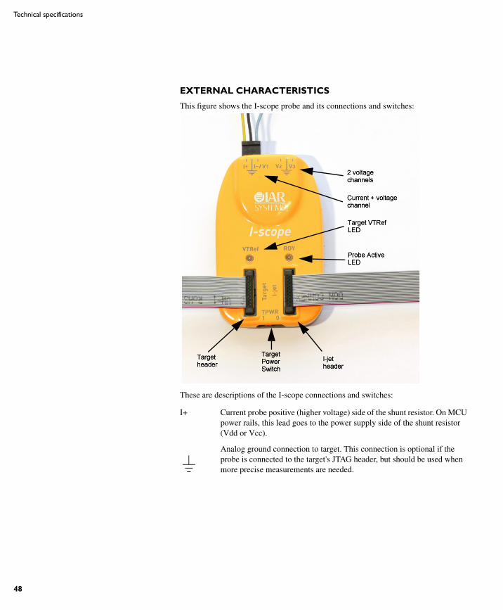
EXTERNAL CHARACTERISTICS
This figure shows the I-scope probe and its connections and switches:
These are descriptions of the I-scope connections and switches:
I+ Current probe positive (higher voltage) side of the shunt resistor. On MCU power rails, this lead goes to the power supply side of the shunt resistor (Vdd or Vcc).
Analog ground connection to target. This connection is optional if the probe is connected to the target's JTAG header, but should be used when more precise measurements are needed.
AFE1_AFE2-1:1
I-scope
49
I-SCOPE PROBE SPECIFICATION
I-
V1
Current probe negative (lower voltage) side of the shunt resistor. On MCU power rails, this lead should be on the MCU side of the shunt resistor (load side).
The shunt resistor should be calculated to allow a voltage drop of around 100 mV when the MCU is operating at its maximum current consumption.
The voltage relative to ground can be measured separately on this input. This allows measurement of both current and voltage at the selected measurement point.
V2 Voltage probe channel for measuring voltages from 0 V to 6 V.
V3 Voltage probe channel for measuring voltages from 0 V to 6 V.
VTRef Target reference voltage LED will turn green when the target voltage is > 1.65 V. This is the minimum target voltage at which the I-jet/I-jet Trace will operate.
RDY Ready LED will turn yellow as soon as the power probe is enabled. After I-jet/I-jet Trace calibrates the probe, the RDY LED will turn green to indicate that I-scope is ready to be used.
Target Connector for a cable that goes to the target's board JTAG header.
I-jet Connector for a cable that goes to I-jet/I-jet Trace.
TPWR Target power switch. When in position 0 (off), it will disconnect the I-jet/I-jet Trace target power rail (TPWR) from going to the target. The default position is 1 (on), which allows I-jet/I-jet Trace to supply 5 V power to target boards. However, target board power measurements will not be accurate and should not be used when I-scope is connected.
Size (W * L * H) 700 mm * 44 mm * 14 mm
ADC resolution 12 bits
Maximum sampling rate 200 ksps
V1, V2, V3 voltage channels range 0 to 6 V
V1, V2, V3 voltage channels resolution
1.49 mV (1 LSB)
V1, V2, V3 voltage channels accuracy
2.98 mV (2 LSB)
AFE1_AFE2-1:1
50
Technical specifications
These are the I-scope specifications per shunt:
Maximum differential voltage between I+ and I- probes
110 mV
1 Ohm shunt 10 Ohm shunt 100 Ohm shunt
Current channel resolution 26.8 uA 2.68 uA 0.268 uA
Current channel accuracy 53.7 uA 5.37 uA 0.537 uA
Current channel measurement range
0-110 mA 0-11 mA 0-1.1 mA
Applications General purpose MCU current and power measurements
Low-power MCU current and power measurements
Measuring power-down and sleep modes current consumption
Table 16: I-scope specifications per shunt