©Ian Sommerville, Robin Abraham 2004CS 361, Summer 2004 Slide 1 Real-time Software Design.
43
©Ian Sommerville, Robin Abraham 2004 CS 361, Summer 2004 Slide 1 Real-time Software Design
-
Upload
donald-charles -
Category
Documents
-
view
213 -
download
0
Transcript of ©Ian Sommerville, Robin Abraham 2004CS 361, Summer 2004 Slide 1 Real-time Software Design.

©Ian Sommerville, Robin Abraham 2004 CS 361, Summer 2004 Slide 1
Real-time Software Design

©Ian Sommerville, Robin Abraham 2004 CS 361, Summer 2004 Slide 2
Real-time systems
Systems which monitor and control their environment.
Inevitably associated with hardware devices• Sensors: Collect data from the system
environment;• Actuators: Change (in some way) the system's
environment; Time is critical. Real-time systems MUST
respond within specified times.

©Ian Sommerville, Robin Abraham 2004 CS 361, Summer 2004 Slide 3
Definition
A real-time system is a software system where the correct functioning of the system depends on the results produced by the system and the time at which these results are produced.
A soft real-time system is a system whose operation is degraded if results are not produced according to the specified timing requirements.
A hard real-time system is a system whose operation is incorrect if results are not produced according to the timing specification.

©Ian Sommerville, Robin Abraham 2004 CS 361, Summer 2004 Slide 4
Stimulus/Response Systems
Given a stimulus, the system must produce a response within a specified time.
Periodic stimuli. Stimuli which occur at predictable time intervals• For example, a temperature sensor may be polled 10
times per second. Aperiodic stimuli. Stimuli which occur at
unpredictable times• For example, a system power failure may trigger an
interrupt which must be processed by the system.

©Ian Sommerville, Robin Abraham 2004 CS 361, Summer 2004 Slide 5
Architectural considerations
Because of the need to respond to timing demands made by different stimuli/responses, the system architecture must allow for fast switching between stimulus handlers.
Timing demands of different stimuli are different so a simple sequential loop is not usually adequate.
Real-time systems are therefore usually designed as cooperating processes with a real-time executive controlling these processes.

©Ian Sommerville, Robin Abraham 2004 CS 361, Summer 2004 Slide 6
A real-time system model
Real-timecontrol system
ActuatorActuator ActuatorActuator
SensorSensorSensor SensorSensorSensor

©Ian Sommerville, Robin Abraham 2004 CS 361, Summer 2004 Slide 7
System elements
Sensor control processes• Collect information from sensors. May buffer
information collected in response to a sensor stimulus.
Data processor• Carries out processing of collected information
and computes the system response. Actuator control processes
• Generates control signals for the actuators.

©Ian Sommerville, Robin Abraham 2004 CS 361, Summer 2004 Slide 8
Sensor/actuator processes
Dataprocessor
Actuatorcontrol
Actuator
Sensorcontrol
Sensor
Stimulus Response
©Ian Sommerville, Robin Abraham 2004 CS 361, Summer 2004 Slide 9
Real-time programming
Hard-real time systems may have to be programmed in assembly language to ensure that deadlines are met.

©Ian Sommerville, Robin Abraham 2004 CS 361, Summer 2004 Slide 10
Java as a real-time language
Java supports lightweight concurrency (threads and synchronized methods) and can be used for some soft real-time systems.
Java 2.0 is not suitable for hard RT programming but real-time versions of Java are now available that address problems such as• Not possible to specify thread execution time• Different timing in different virtual machines• Uncontrollable garbage collection• Not possible to discover queue sizes for shared resources• Not possible to access system hardware

©Ian Sommerville, Robin Abraham 2004 CS 361, Summer 2004 Slide 11
System design
Design both the hardware and the software associated with system. Partition functions to either hardware or software.
Design decisions should be made on the basis on non-functional system requirements.
Hardware delivers better performance but potentially longer development and less scope for change.

©Ian Sommerville, Robin Abraham 2004 CS 361, Summer 2004 Slide 12
R-T systems design process
Identify the stimuli to be processed and the required responses to these stimuli.
For each stimulus and response, identify the timing constraints.
Aggregate the stimulus and response processing into concurrent processes. A process may be associated with each class of stimulus and response.

©Ian Sommerville, Robin Abraham 2004 CS 361, Summer 2004 Slide 13
R-T systems design process
Design algorithms to process each class of stimulus and response. These must meet the given timing requirements.
Design a scheduling system which will ensure that processes are started in time to meet their deadlines.
Integrate using a real-time operating system.

©Ian Sommerville, Robin Abraham 2004 CS 361, Summer 2004 Slide 14
Timing constraints
May require extensive simulation and experiment to ensure that these are met by the system.
May mean that certain design strategies such as object-oriented design cannot be used because of the additional overhead involved.
May mean that low-level programming language features have to be used for performance reasons.

©Ian Sommerville, Robin Abraham 2004 CS 361, Summer 2004 Slide 15
Real-time system modelling
Finite state machines can be used for modelling real-time systems.
However, FSM models lack structure. Even simple systems can have a complex model.
The UML includes notations for defining state machine models

©Ian Sommerville, Robin Abraham 2004 CS 361, Summer 2004 Slide 16
Petrol pump state model
Cardinserted
into reader
Timeout
Resettingdo: display CC
error
Initialising
do: initialisedisplay
Paying
Stopped
Reading
do: get CCdetails
Waiting
do: display welcome
do:deliver fuel
do: debitCC account
Payment ack.
Ready Delivering
update displayNozzle
trigger on
Nozzle trigger off
Nozzle trigger on
Hose inholster
do: validatecredit card
Validating
Invalid card
Card removedCard OK
Hose out of holster
Timeout

©Ian Sommerville, Robin Abraham 2004 CS 361, Summer 2004 Slide 17
Real-time operating systems
Real-time operating systems are specialised operating systems which manage the processes in the RTS.
Responsible for process management and resource (processor and memory) allocation.
Do not normally include facilities such as file management.
14

©Ian Sommerville, Robin Abraham 2004 CS 361, Summer 2004 Slide 18
Operating system components
Real-time clock• Provides information for process scheduling.
Interrupt handler• Manages aperiodic requests for service.
Scheduler• Chooses the next process to be run.
Resource manager• Allocates memory and processor resources.
Dispatcher• Starts process execution.

©Ian Sommerville, Robin Abraham 2004 CS 361, Summer 2004 Slide 19
Non-stop system components
Configuration manager• Responsible for the dynamic reconfiguration of the
system software and hardware. Hardware modules may be replaced and software upgraded without stopping the systems.
Fault manager• Responsible for detecting software and hardware faults
and taking appropriate actions (e.g. switching to backup disks) to ensure that the system continues in operation.

©Ian Sommerville, Robin Abraham 2004 CS 361, Summer 2004 Slide 20
Real-time OS components
Process resourcerequirements
Scheduler
Schedulinginformation
Resourcemanager
Despatcher
Real-timeclock
Processesawaiting
resources
Readylist
Interrupthandler
Availableresource
list
Processorlist
Executing process
Readyprocesses
Releasedresources
©Ian Sommerville, Robin Abraham 2004 CS 361, Summer 2004 Slide 21
Process priority
The processing of some types of stimuli must sometimes take priority.
Interrupt level priority. Highest priority which is allocated to processes requiring a very fast response.
Clock level priority. Allocated to periodic processes.
Within these, further levels of priority may be assigned.

©Ian Sommerville, Robin Abraham 2004 CS 361, Summer 2004 Slide 22
Interrupt servicing
Control is transferred automatically to a pre-determined memory location.
This location contains an instruction to jump to an interrupt service routine.
Further interrupts are disabled, the interrupt serviced and control returned to the interrupted process.
Interrupt service routines MUST be short, simple and fast.

©Ian Sommerville, Robin Abraham 2004 CS 361, Summer 2004 Slide 23
Process management
Concerned with managing the set of concurrent processes.
Periodic processes are executed at pre-specified time intervals.
The RTOS uses the real-time clock to determine when to execute a process taking into account:• Process period - time between executions.• Process deadline - the time by which processing must be
complete.

©Ian Sommerville, Robin Abraham 2004 CS 361, Summer 2004 Slide 24
RT process management
Resource manager
Allocate memoryand processor
Scheduler
Choose processfor execution
Despatcher
Start execution on anavailable processor
©Ian Sommerville, Robin Abraham 2004 CS 361, Summer 2004 Slide 25
Scheduling strategies
Non pre-emptive scheduling• Once a process has been scheduled for execution, it runs
to completion or until it is blocked for some reason (e.g. waiting for I/O).
Pre-emptive scheduling• The execution of an executing processes may be stopped
if a higher priority process requires service.
Scheduling algorithms• Round-robin• Rate monotonic• Shortest deadline first.
©Ian Sommerville, Robin Abraham 2004 CS 361, Summer 2004 Slide 26
Monitoring and control systems
Important class of real-time systems.
Continuously check sensors and take actions depending on sensor values.
Monitoring systems examine sensors and report their results.
Control systems take sensor values and control hardware actuators.

©Ian Sommerville, Robin Abraham 2004 CS 361, Summer 2004 Slide 27
Generic architecture
S1
S2
S3
P (S1)
P (S2)
P (S1)
Monitoringprocesses
Controlprocesses
P (A1)
P (A2)
P (A1)
A1
A2
A3
P (A4) A4
Testingprocess
Control panelprocesses

©Ian Sommerville, Robin Abraham 2004 CS 361, Summer 2004 Slide 28
Burglar alarm system
A system is required to monitor sensors on doors and windows to detect the presence of intruders in a building.
When a sensor indicates a break-in, the system switches on lights around the area and calls police automatically.
The system should include provision for operation without a mains power supply.

©Ian Sommerville, Robin Abraham 2004 CS 361, Summer 2004 Slide 29
Burglar alarm system
Sensors• Movement detectors, window sensors, door sensors;• 50 window sensors, 30 door sensors and 200 movement
detectors;• Voltage drop sensor.
Actions• When an intruder is detected, police are called
automatically;• Lights are switched on in rooms with active sensors;• An audible alarm is switched on;• The system switches automatically to backup power
when a voltage drop is detected.

©Ian Sommerville, Robin Abraham 2004 CS 361, Summer 2004 Slide 30
The R-T system design process
Identify stimuli and associated responses. Define the timing constraints associated with
each stimulus and response. Allocate system functions to concurrent
processes. Design algorithms for stimulus processing and
response generation. Design a scheduling system which ensures that
processes will always be scheduled to meet their deadlines.

©Ian Sommerville, Robin Abraham 2004 CS 361, Summer 2004 Slide 31
Stimuli to be processed
Power failure• Generated aperiodically by a circuit monitor.
When received, the system must switch to backup power within 50 ms.
Intruder alarm• Stimulus generated by system sensors.
Response is to call the police, switch on building lights and the audible alarm.
©Ian Sommerville, Robin Abraham 2004 CS 361, Summer 2004 Slide 32
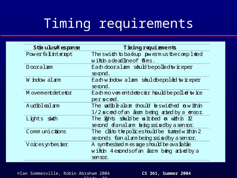
Timing requirements
Stimulus/Response Timing requirementsPower fail interrupt The switch to backup power must be completed
within a deadline of 50 ms.Door alarm Each door alarm should be polled twice per
second.Window alarm Each window alarm should be polled twice per
second.Movement detector Each movement detector should be polled twice
per second.Audible alarm The audible alarm should be switched on within
1/2 second of an alarm being raised by a sensor.Lights switch The lights should be switched on within 1/2
second of an alarm being raised by a sensor.Communications The call to the police should be started within 2
seconds of an alarm being raised by a sensor.Voice synthesiser A synthesised message should be available
within 4 seconds of an alarm being raised by asensor.

©Ian Sommerville, Robin Abraham 2004 CS 361, Summer 2004 Slide 33
Burglar alarm system processes
Lighting controlprocess
Audible alarmprocess
Voice synthesiserprocess
Alarm systemprocess
Power switchprocess
Building monitorprocess
Communicationprocess
Door sensorprocess
Movementdetector process
Window sensorprocess
560 Hz
60 Hz400 Hz 100 Hz
Power failureinterrupt
Alarm system
Building monitor
Alarm system
Alarm system
Alarm system
Detector status Sensor status Sensor status
Room number
Alert message
Room number
Room number

©Ian Sommerville, Robin Abraham 2004 CS 361, Summer 2004 Slide 34
Control systems
A burglar alarm system is primarily a monitoring system. It collects data from sensors but no real-time actuator control.
Control systems are similar but, in response to sensor values, the system sends control signals to actuators.
An example of a monitoring and control system is a system that monitors temperature and switches heaters on and off.

©Ian Sommerville, Robin Abraham 2004 CS 361, Summer 2004 Slide 35
A temperature control system
Thermostatprocess
Sensorprocess
Furnacecontrol process
Heater controlprocess
500 Hz
500 Hz
Thermostat process500 Hz
Sensorvalues
Switch commandRoom number
©Ian Sommerville, Robin Abraham 2004 CS 361, Summer 2004 Slide 36
Data acquisition systems
Collect data from sensors for subsequent processing and analysis.
Data collection processes and processing processes may have different periods and deadlines.
Data collection may be faster than processing e.g. collecting information about an explosion.
Circular or ring buffers are a mechanism for smoothing speed differences.

©Ian Sommerville, Robin Abraham 2004 CS 361, Summer 2004 Slide 37
Data acquisition architecture
DisplayProcess
dataSensor data
bufferSensorprocess
Sensoridentifier and
value
Sensors (each data flow is a sensor value)
Sensoridentifier and
value
Processdata
Sensor databuffer
Sensorprocess
Sensoridentifier and
value
Sensoridentifier and
value
s1
s2
s3
s4
s5
s6
©Ian Sommerville, Robin Abraham 2004 CS 361, Summer 2004 Slide 38
Reactor data collection
A system collects data from a set of sensors monitoring the neutron flux from a nuclear reactor.
Flux data is placed in a ring buffer for later processing.
The ring buffer is itself implemented as a concurrent process so that the collection and
processing processes may be synchronized.
©Ian Sommerville, Robin Abraham 2004 CS 361, Summer 2004 Slide 39
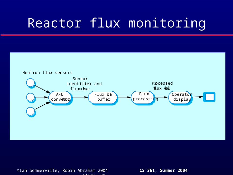
Reactor flux monitoring
Operatordisplay
Fluxprocessing
Flux databuffer
A-Dconvertor
Sensoridentifier and
flux valueProcessedflux level
Neutron flux sensors

©Ian Sommerville, Robin Abraham 2004 CS 361, Summer 2004 Slide 40
A ring buffer
Consumerprocess
Producerprocess

©Ian Sommerville, Robin Abraham 2004 CS 361, Summer 2004 Slide 41
Mutual exclusion
Producer processes collect data and add it to the buffer. Consumer processes take data from the buffer and make elements available.
Producer and consumer processes must be mutually excluded from accessing the same element.
The buffer must stop producer processes adding information to a full buffer and consumer processes trying to take information from an empty buffer.

©Ian Sommerville, Robin Abraham 2004 CS 361, Summer 2004 Slide 42
Key points
Real-time system correctness depends not just on what the system does but also on how fast it reacts.
A general RT system model involves associating processes with sensors and actuators.
Real-time systems architectures are usually designed as a number of concurrent processes.

©Ian Sommerville, Robin Abraham 2004 CS 361, Summer 2004 Slide 43
Key points
Real-time operating systems are responsible for process and resource management.
Monitoring and control systems poll sensors and send control signal to actuators.
Data acquisition systems are usually organised according to a producer consumer model.