Iai rcs3 ct8 c-cj0210-1a-ust-1-0114
8
www.intelligentactuator.com RCS3-CT8C/CTZ5C ROBO Cylinder ® High-speed Type
-
Upload
electromate -
Category
Technology
-
view
39 -
download
1
Transcript of Iai rcs3 ct8 c-cj0210-1a-ust-1-0114

w w w . i n t e l l i g e n t a c t u a t o r. c o m
RCS3-CT8C/CTZ5CROBO Cylinder® High-speed Type

1
Achieving the Max. Speed of 2500 mm/s and Max. Acceleration of 3.2 G (Instantaneous Max. Acceleration of 4.8 G)Improved High-speed Performance Reduces the Cycle Time
The maximum speed of 2500 mm/s (1.4 times the level of an existing model) and maximum acceleration/deceleration of 3.2 G (3.2 times the level of an existing model) are realized by increasing the size and speed of the motor, revising the structural members, and adding other changes to the RCS3 series boasting the highest speed among the ROBO Cylinder family. This cuts the travel time by 50% compared to an existing model (based on the conditions applicable to the graph on the right).
A single-axis controller offering excellent cost performance, and a multi-axis controller capable of operating up to three CT8C axes, are available.
RCS3-CT8C(for horizontal axis)
RCS3-CTZ5C(for vertical axis)
ROBO Cylinder High-speed Type
The CT8C and CTZ5C can be combined and used as a high-speed transfer system. Such a system is ideal for transferring light objects at high speed, such as supplying parts of various types including electrical/electronic parts, PC/smart phone parts and the like.
1. 1.4 Times the Max. Speed and 3.2 Times the Max. Acceleration/Deceleration (Compared to the Existing RCS3-SA8C)
2. Supporting Single/Multi-axis Controllers
3. Application
Single-axis controller < SCON-CA-CT4 >
Multi-axis controller < XSEL-PCT/QCT>
Transfer & placement system Inter-pallet work part placement system
Comparison of travel time over a distance of 500 mm
0.31 sec.
0.62 sec.
50%less
Travel time
Acceleration 1GSpeed 1800mm/sLoad 2kg
RCS3-SA8C
Acceleration 3.2GSpeed 2500mm/sLoad 5kg
RCS3-CT8C
2
www.intelligentactuator.com
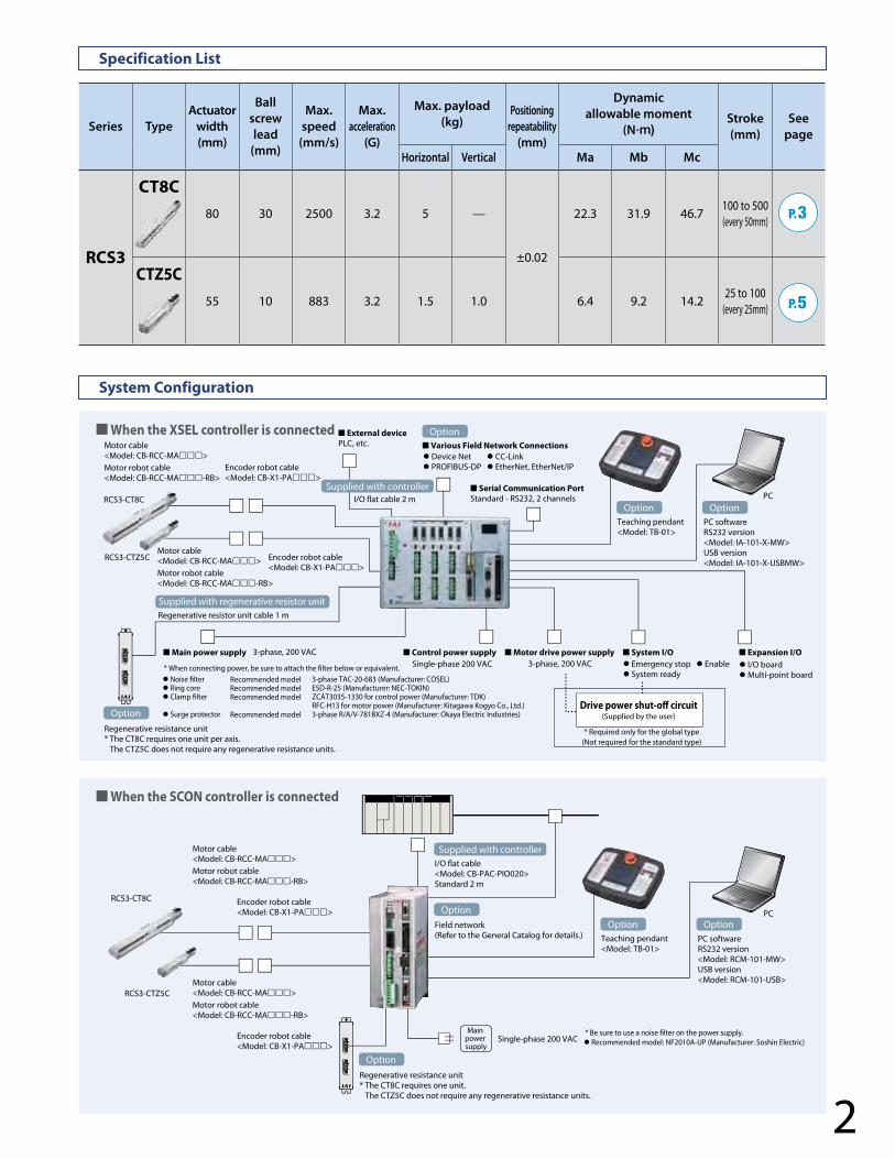
Specification List
System Configuration
Series TypeActuator
width(mm)
Ball screw lead
(mm)
Max. speed
(mm/s)
Max.acceleration
(G)
Max. payload(kg)
Positioningrepeatability
(mm)
Dynamic allowable moment
(N·m)Stroke(mm)
Seepage
Horizontal Vertical Ma Mb Mc
RCS3
CT8C80 30 2500 3.2 5 —
±0.02
22.3 31.9 46.7100 to 500(every 50mm)
CTZ5C55 10 883 3.2 1.5 1.0 6.4 9.2 14.2
25 to 100(every 25mm)
P.3
P.5
RB+
RB -
RB OUT
RB+
RB -
RB IN
RB +
RB -
RB OUT
RB +
RB -
RB IN
Drive power shut-o� circuit(Supplied by the user)
Motor cable<Model: CB-RCC-MA���>Motor robot cable<Model: CB-RCC-MA���-RB>
Encoder robot cable<Model: CB-X1-PA���>
Motor cable<Model: CB-RCC-MA���>Motor robot cable<Model: CB-RCC-MA���-RB>
Encoder robot cable<Model: CB-X1-PA���>
Motor cable<Model: CB-RCC-MA���>Motor robot cable<Model: CB-RCC-MA���-RB>
Encoder robot cable<Model: CB-X1-PA���>
Motor cable<Model: CB-RCC-MA���>Motor robot cable<Model: CB-RCC-MA���-RB>
Encoder robot cable<Model: CB-X1-PA���>
* When connecting power, be sure to attach the lter below or equivalent.
* Be sure to use a noise lter on the power supply.
3-phase, 200 VAC■ Main power supply ■ Control power supply ■ Motor drive power supply ■ System I/O ■ Expansion I/O� Emergency stop � Enable� System ready
* Required only for the global type(Not required for the standard type)
RCS3-CT8C
RCS3-CTZ5C
RCS3-CTZ5C
RCS3-CT8C
PC
� I/O board� Multi-point board
Single-phase 200 VAC 3-phase, 200 VAC
■ External devicePLC, etc.
PC
PC softwareRS232 version <Model: IA-101-X-MW>USB version<Model: IA-101-X-USBMW>
I/O �at cable<Model: CB-PAC-PIO020>Standard 2 m
Single-phase 200 VACMain
power supply
Field network(Refer to the General Catalog for details.)
Regenerative resistance unit * The CT8C requires one unit per axis. The CTZ5C does not require any regenerative resistance units.
Regenerative resistance unit * The CT8C requires one unit. The CTZ5C does not require any regenerative resistance units.
■ Serial Communication PortStandard - RS232, 2 channels
Regenerative resistor unit cable 1 m
I/O �at cable 2 m
� Device Net � CC-Link� PROFIBUS-DP � EtherNet, EtherNet/IP
■ Various Field Network Connections
Teaching pendant<Model: TB-01>
PC softwareRS232 version <Model: RCM-101-MW>USB version<Model: RCM-101-USB>
Teaching pendant<Model: TB-01>
� Noise lter� Ring core � Clamp lter
� Surge protector
Recommended modelRecommended modelRecommended model
Recommended model
3-phase TAC-20-683 (Manufacturer: COSEL)ESD-R-25 (Manufacturer: NEC-TOKIN)ZCAT3035-1330 for control power (Manufacturer: TDK)RFC-H13 for motor power (Manufacturer: Kitagawa Kogyo Co., Ltd.)3-phase R/A/V-781BXZ-4 (Manufacturer: Okaya Electric Industries)
� Recommended model: NF2010A-UP (Manufacturer: Soshin Electric)
Option
OptionOption
OptionOption
Option
Option
Option
Supplied with controller
Supplied with controller
Supplied with regenerative resistor unit
� When the XSEL controller is connected
� When the SCON controller is connected
3
➂Option List
Actuator Specifications
Actuator Specifications Table■ Stroke and Max. Speed
L
L
Ma MaMb Mc Mb
Allowable load moment directions Overhang load length
Model Motor output (W)
Lead(mm)
Maximum payload Rated thrust (N)
Stroke(mm)Horizontal (kg) Vertical (kg)
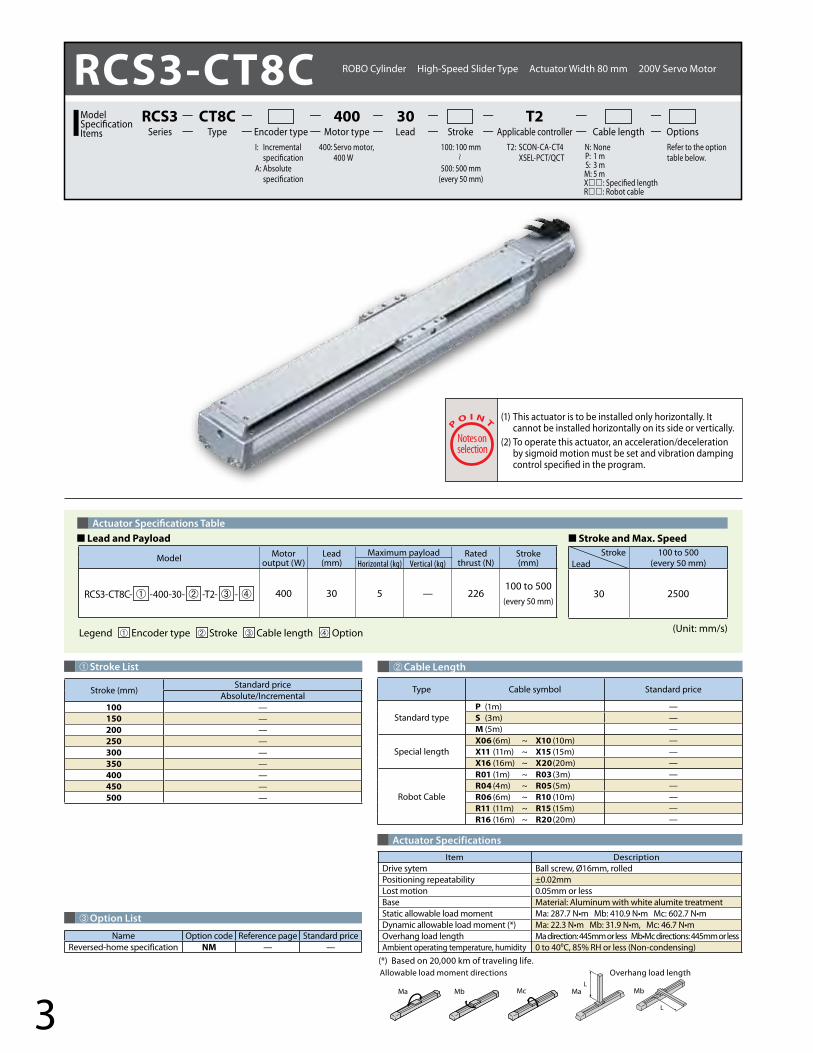
RCS3-CT8C- ➀ -400-30- ➁ -T2- ➂ - ➃ 400 30 5 — 226100 to 500
(every 50 mm)
100 to 500(every 50 mm)
30 2500
➀Stroke List
Stroke (mm)Standard price
Absolute/Incremental100 —150 —200 —250 —300 —350 —400 —450 —500 —
Item DescriptionDrive sytem Ball screw, Ø16mm, rolled Positioning repeatability ±0.02mmLost motion 0.05mm or lessBase Material: Aluminum with white alumite treatment Static allowable load moment Ma: 287.7 N•m Mb: 410.9 N•m Mc: 602.7 N•mDynamic allowable load moment (*) Ma: 22.3 N•m Mb: 31.9 N•m, Mc: 46.7 N•mOverhang load length Ma direction: 445mm or less Mb•Mc directions: 445mm or lessAmbient operating temperature, humidity 0 to 40ºC, 85% RH or less (Non-condensing)
Name Option code Reference page Standard priceReversed-home specification NM — —
(*) Based on 20,000 km of traveling life.
LeadStroke
➁Cable Length
Type Cable symbol Standard price
Standard typeP (1m) —S (3m) —M (5m) —
Special lengthX06 (6m) ~ X10 (10m) —X11 (11m) ~ X15 (15m) —X16 (16m) ~ X20 (20m) —
Robot Cable
R01 (1m) ~ R03 (3m) —R04 (4m) ~ R05 (5m) —R06 (6m) ~ R10 (10m) —R11 (11m) ~ R15 (15m) —R16 (16m) ~ R20 (20m) —
Legend ➀ Encoder type ➁ Stroke ➂ Cable length ➃ Option (Unit: mm/s)
RCS3-CT8C ROBO Cylinder High-Speed Slider Type Actuator Width 80 mm 200V Servo Motor
400: Servo motor, 400 W
I: Incremental specificationA: Absolute specification
T2: SCON-CA-CT4 XSEL-PCT/QCT
N: None P: 1 m S: 3 m M: 5 mX : Specified lengthR : Robot cable
Refer to the option table below.
Lead Stroke Cable length OptionsTypeCT8C
Encoder type Motor type400
Applicable controllerT2
SeriesRCS3Model
SpecificationItems
100: 100 mm
500: 500 mm(every 50 mm)
30
(1) This actuator is to be installed only horizontally. It cannot be installed horizontally on its side or vertically.
(2) To operate this actuator, an acceleration/deceleration by sigmoid motion must be set and vibration damping control specified in the program.
■ Lead and Payload

4
Dimensional Drawings
70
89
5580 4.5
1744.5
Cable jointconnector *1
Actuator cable(400mm)
8-M6, depth 122-ø 6H7, depth 10
(Tolerance for reamed hole pitch±0.02)
83
60
60
27.6
9.5
13.5
184.53
39
ME (*2) SE
Ma momentO�set reference position*3
8078
65
139
.5
44
0.5
5.5
Detailed view of Z
Reference surface
3Stroke + 89 78
L
Home ME *2
37.5 29.55050 E F×100P
13810
40
Oblong hole, depth 6 from the bottom of the base6 Bottom of the base
98
B(Pitch of oblong hole and reamed hole)
50±0.02(Pitch of reamed holes)
C(Pitch of reamed holes)
+0.0
12 0
6
60
4-ø5 H7depth 6 from the bottom of the base
134±0.05 (Pitch of reamed holes)
A
29.5±0.05(Reamed hole position)
D-M5, depth 10+0.012 0
5
37.5
Z
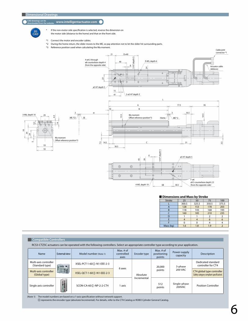
* If the non-motor side specification is selected, reverse the dimension on the motor side (distance to the home) and that on the front side.
*1 Connect the motor and encoder cables.*2 During the home return, the slider moves to the ME, so pay attention not to let the slider hit surrounding parts.*3 Reference position used when calculating the Ma moment.
CAD drawings can be downloaded from the website. www.intelligentactuator.com
■ Dimensions and Mass by Stroke
Compatible Controllers
RCS3-CT8C actuators can be operated with the following controllers. Select an appropriate controller type according to your application.
(Note 1) The model numbers are based on a 1-axis specification without network support. represents the encoder type (absolute/incremental). For details, refer to the CT4 Catalog or ROBO Cylinder General Catalog.(Note 2) Up to 3 axes are supported if all of them are RCS3-CT8Cs.
Name External view Model number (Note 1)Max. # of
controlled axes
Encoder typeMax. # of
positioning points
Power-supplycapacity Description
Multi-axis controller(Standard type) XSEL-PCT-1-400 -N1-EEE-2-3
6 axes(Note 2)
AbsoluteIncremental
20,000points
3-phase 200 VAC
Dedicated standard controller for CT4
Multi-axis controller(Global type) XSEL-QCT-1-400 -N1-EEE-2-3 CT4 global type controller
(Safety category compliant specification)
Single axis controller SCON-CA-400 -NP-2-2-CT4 1 axis 512points
Single-phase 200VAC Position controller
Stroke 100 150 200 250 300 350 400 450 500L 404 454 504 554 604 654 704 754 804A 251 301 351 401 451 501 551 601 651B 84 134 184 234 284 334 384 434 484C 134 184 234 284 334 384 434 484 534D 8 10 10 12 12 14 14 16 16E 84 34 84 34 84 34 84 34 84F 0 1 1 2 2 3 3 4 4
Mass (kg) 4.2 4.5 4.8 5.1 5.4 5.7 6 6.3 6.6
5
➂Option List
Actuator Specifications
Actuator Specifications Table■ Stroke and Max. Speed
L
L
Ma MaMb Mc Mb
Allowable load moment directions Overhang load length
➁Cable Length
Type Cable symbol Standard price
Standard typeP (1m) —S (3m) —M (5m) —
Special lengthX06 (6m) ~ X10 (10m) —X11 (11m) ~ X15 (15m) —X16 (16m) ~ X20 (20m) —
Robot Cable
R01 (1m) ~ R03 (3m) —R04 (4m) ~ R05 (5m) —R06 (6m) ~ R10 (10m) —R11 (11m) ~ R15 (15m) —R16 (16m) ~ R20 (20m) —
Legend ➀ Encoder type ➁ Stroke ➂ Cable length ➃ Option (Unit: mm/s)
■ Lead and Payloads
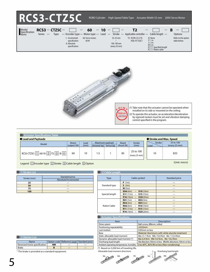
(1) Take note that this actuator cannot be operated when installed on its side or mounted on the ceiling.
(2) To operate this actuator, an acceleration/deceleration by sigmoid motion must be set and vibration damping control specified in the program.
Item DescriptionDrive sytem Ball screw, Ø8mm, rolled Positioning repeatability ±0.02mmLost motion 0.05mm or lessBase Material: Aluminum with white alumite treatment Static allowable load moment Ma: 51.1 N•m Mb: 73.0 N•m Mc: 112.4 N•mDynamic allowable load moment (*) Ma: 6.4 N•m Mb: 9.2 N•m, Mc: 14.2 N•mOverhang load length Ma direction: 50mm or less Mb•Mc directions: 50mm or lessAmbient operating temperature, humidity 0 to 40ºC, 85% RH or less (Non-condensing)
(*) Based on 5,000 km of traveling life.* The brake is provided as a standard equipment.
Name Option code Reference page Standard priceReversed-home specification NM — —Brake B — —
Model Motor output (W)
Lead(mm)
Maximum payload Rated thrust (N)
Stroke(mm)Horizontal (kg) Vertical (kg)
RCS3-CTZ5C- ➀ -60-10- ➁ -T2- ➂ -B- ➃ 60 10 1.5 1 8525 to 100
(every 25 mm)
25 to 100(every 25 mm)
10 833
➀Stroke List
Stroke (mm)Standard price
Absolute/Incremental25 —50 —75 —
100 —
LeadStroke
RCS3-CTZ5C ROBO Cylinder High-Speed Table Type Actuator Width 55 mm 200V Servo Motor
60: Servo motor, 60 W
I: Incremental specificationA: Absolute specification
T2: SCON-CA-CT4 XSEL-PCT/QCT
N: None P: 1 m S: 3 m M: 5 mX : Specified lengthR : Robot cable
Refer to the option table below.
Lead Stroke Cable length OptionsTypeCTZ5C
Encoder type Motor type60
Applicable controllerT2
SeriesRCS3Model
SpecificationItems
25: 25 mm
100: 100 mm(every 25 mm)
10 B
6
Dimensional Drawings
* If the non-motor side specification is selected, reverse the dimension on the motor side (distance to the home) and that on the front side.
*1 Connect the motor and encoder cables.*2 During the home return, the slider moves to the ME, so pay attention not to let the slider hit surrounding parts.*3 Reference position used when calculating the Ma moment.
CAD drawings can be downloaded from the website. www.intelligentactuator.com
Compatible Controllers
6
Cable jointconnector *1
Actuator cable(400mm)
3-M6, depth 10
4-M5, depth 10
E-M5, depth 6
Ma momentO�set reference position*3
Ma momentO�set reference position*3 Home ME *2
F-ø6ø9.5 counterbore depth 2.5(from the opposite side)
4-ø4.5 throughø8 counterbore depth 4(from the opposite side)
ø5 H7 depth 5
ø5 H7 depth 5
2-ø3 H7 depth 5
5 H
7 d
epth
5
5 H
7 d
epth
5
st3
53
5
14
6.529
24
55
55
34
13.5
ME (*2) SE
3
14.5
56.5
13.5
10 B
A 77.5 95
L
C 31 3.5
16.5
7.5
54.5
68 30.5
6
26
21 D×40
40
15
41
22
24
45
RCS3-CTZ5C actuators can be operated with the following controllers. Select an appropriate controller type according to your application.
(Note 1) The model numbers are based on a 1-axis specification without network support. represents the encoder type (absolute/incremental). For details, refer to the CT4 Catalog or ROBO Cylinder General Catalog.
Name External view Model number (Note 1)Max. # of
controlled axes
Encoder typeMax. # of
positioning points
Power-supplycapacity Description
Multi-axis controller(Standard type) XSEL-PCT-1-60 -N1-EEE-2-3
6 axes
AbsoluteIncremental
20,000points
3-phase 200 VAC
Dedicated standard controller for CT4
Multi-axis controller(Global type) XSEL-QCT-1-60 -N1-EEE-2-3 CT4 global type controller
(Safety category compliant specification)
Single axis controller SCON-CA-60 -NP-2-2-CT4 1 axis 512points
Single-phase 200VAC Position Controller
■ Dimensions and Mass by StrokeStroke 25 50 75 100
L 300.5 325.5 350.5 375.5A 128 153 178 203B 118 143 168 193C 160 185 210 235D 1 1 2 2E 4 4 6 6F 0 0 4 4
Mass (kg) 1.6 1.8 1.9 2

CJ0210-1A-UST-1-0114
IAI America, Inc.Headquarters: 2690 W. 237th Street, Torrance, CA 90505 (800) 736-1712Chicago Office: 1261 Hamilton Parkway, Itasca, IL 60143 (800) 944-0333Atlanta Office: 1220 Kennestone Circle, Suite 108, Marietta, GA 30066 (888) 354-9470
www.intelligentactuator.com
IAI Industrieroboter GmbHOber der Röth 4, D-65824 Schwalbach am Taunus, Germany
IAI Robot (Thailand), CO., Ltd.825 PhairojKijja Tower 12th Floor, Bangna-Trad RD.,Bangna, Bangna, Bangkok 10260, Thailand
The information contained in this product brochure may change without prior notice due to product improvements.
*1 Calculate the total wattage based on 800 W per axis for the RCS3-CT8C and 120 W per axis for the RCS3-CTZ5C. *2 According to the basic specification. The capacity will vary if an expansion I/O box, field network, etc., are added. *3 When the controller is equipped with an absolute battery, brake mechanism, expansion I/O box.
Supported Controllers
Notes on Installation
Controller series/type SCON-CA-CT4 XSEL-PCT (standard) type XSEL-QCT (global) type
Exterior view
Total wattage of connectable axes 400W 2400W (*1)
Number of controlled axes 1 axis 6 axes 6 axes
Control power input AC200/230Single-phase ±10%
AC200/230Single-phase -15%, +10%
Motor power input AC200/230Single-phase ±10%
AC200/2303-phase ±10%
Power frequency 50/60 Hz
Insulation resistance 500 VDC, 10 MΩ or more 10 MΩ or more (between the power terminal and I/O terminal, and between all external terminals and the case, at 500 VDC)
Withstand voltage 1500 VAC (1 minute)
Control power capacity 48 VA 94VA (*2)
Motor power capacity RCS3-CT8C is operated: 1230 VARCS3-CTZ5C is operated: 197 VA
RCS3-CT8C is operated: 1230 VA per axisRCS3-CTZ5C is operated: 197 VA per axis
Position detection method Incremental encoder/Absolute encoder
Incremental encoder/Absolute encoder
Safety circuit configuration Redundancy not supported Redundancy not supported Redundancy not supported
Drive-source cutoff method Cut off by an internal relay Cut off by an internal relay External safety circuit
Enable input — Contact B input (internally powered) Contact B input (externally powered, redundant)
Number of programs — 128 programs
Number of program steps — 9,999 steps (total)
Number of multi-tasking programs — 16 programs
Number of positioning points 512 points 20,000 points (total)
Data storage device Nonvolatile memory (FRAM) Flash ROM + SRAM, backed up by a battery
Data input method Teaching pendant or PC software
Standard I/Os 16 input points/16 output points (NPN/PNP selectable)
One PIO board with 48 I/O points (NPN/PNP) or PIO board with 96 I/O points (NPN/PNP) can be installed.
Expansion I/Os — Up to three PIO boards with 48 I/O points (NPN/PNP) or PIO boards with 96 I/O points (NPN/PNP) can be installed.
Operating ambient temperature/humidity/ambience
0 to 40°C, 85% RH or less (Non-condensing); no corrosive gases
0 to 40ºC, 10 to 95% RH (Non-condensing); no corrosive gases; no significant dust
Controller mass (*3) Approx. 1.2 kg 5.2 kg to 5.7 kg 4.5 kg to 5 kg
The RCS3-CT8C/RCS3-CTZ5C can be operated with the controllers listed below. Select a controller that matches the specifications of your system.
The platform on which to install the high-speed type ROBO Cylinder shall have enough rigidity and must be installed in such a way that the platform will not move as the ROBO Cylinder moves.
Consider the rigidity to withstand this load moment.
AF
Platform
mH
Reactive force: F = mA m: Mass of the moving part A: Acceleration
Moment load: M = FH = mAH H: Distance from the platform to the center of gravity of the moving part
● The reactive force that generates when the ROBO Cylinder moves is determined by the mass of the moving part and the acceleration.
● The platform receives the above reactive force and the moment load due to the height H to the center-of-gravity position.