IAEA TECDOC SERIES - IAEA Scientific and Technical ... · PDF fileIAEA TECDOC 1720 Operation...
90
Operation and Licensing of Mixed Cores in Water Cooled Reactors IAEA TECDOC 1720 Operation and Licensing of Mixed Cores in Water Cooled Reactors @ IAEA TECDOC 1720 TECDOC No. 1720 IAEA TECDOC SERIES
-
Upload
duongxuyen -
Category
Documents
-
view
281 -
download
3
Transcript of IAEA TECDOC SERIES - IAEA Scientific and Technical ... · PDF fileIAEA TECDOC 1720 Operation...

Operation and Licensing of M
ixed Cores in Water Cooled Reactors
IAEA TECDOC 1720
Operation and Licensing of Mixed Cores in Water Cooled Reactors
@
IAEA TECDOC 1720
TECDOC No. 1720
IAEA TECDOC SERIES

OPERATION AND LICENSING OF MIXED CORES IN
WATER COOLED REACTORS

AFGHANISTANALBANIAALGERIAANGoLAARGENTINAARMENIAAUSTRALIAAUSTRIAAZERBAIJANBAHRAINBANGLADESHBELARUSBELGIUMBELIZEBENINBoLIVIABoSNIA AND HERZEGoVINABoTSWANABRAZILBULGARIABURKINA FASoBURUNDICAMBoDIACAMERooNCANADACENTRAL AFRICAN
REPUBLICCHADCHILECHINACoLoMBIACoNGoCoSTA RICACÔTE D’IVoIRECRoATIACUBACYPRUSCZECH REPUBLICDEMoCRATIC REPUBLIC
oF THE CoNGoDENMARKDoMINICADoMINICAN REPUBLICECUADoREGYPTEL SALVADoRERITREAESToNIAETHIoPIAFIJIFINLANDFRANCEGABoNGEoRGIAGERMANYGHANAGREECE
GUATEMALAHAITIHoLY SEEHoNDURASHUNGARYICELANDINDIAINDoNESIAIRAN, ISLAMIC REPUBLIC oF IRAQIRELANDISRAELITALYJAMAICAJAPANJoRDANKAZAKHSTANKENYAKoREA, REPUBLIC oFKUWAITKYRGYZSTANLAo PEoPLE’S DEMoCRATIC
REPUBLICLATVIALEBANoNLESoTHoLIBERIALIBYALIECHTENSTEINLITHUANIALUXEMBoURGMADAGASCARMALAWIMALAYSIAMALIMALTAMARSHALL ISLANDSMAURITANIAMAURITIUSMEXICoMoNACoMoNGoLIAMoNTENEGRoMoRoCCoMoZAMBIQUEMYANMARNAMIBIANEPALNETHERLANDSNEW ZEALANDNICARAGUANIGERNIGERIANoRWAYoMANPAKISTANPALAU
PANAMAPAPUA NEW GUINEAPARAGUAYPERUPHILIPPINESPoLANDPoRTUGALQATARREPUBLIC oF MoLDoVARoMANIARUSSIAN FEDERATIoNRWANDASAUDI ARABIASENEGALSERBIASEYCHELLESSIERRA LEoNESINGAPoRESLoVAKIASLoVENIASoUTH AFRICASPAINSRI LANKASUDANSWAZILANDSWEDENSWITZERLANDSYRIAN ARAB REPUBLICTAJIKISTANTHAILANDTHE FoRMER YUGoSLAV
REPUBLIC oF MACEDoNIAToGoTRINIDAD AND ToBAGoTUNISIATURKEYUGANDAUKRAINEUNITED ARAB EMIRATESUNITED KINGDoM oF
GREAT BRITAIN AND NoRTHERN IRELAND
UNITED REPUBLIC oF TANZANIA
UNITED STATES oF AMERICAURUGUAYUZBEKISTANVENEZUELAVIETNAMYEMENZAMBIAZIMBABWE
The following States are Members of the International Atomic Energy Agency:
The Agency’s Statute was approved on 23 october 1956 by the Conference on the Statute of the IAEA held at United Nations Headquarters, New York; it entered into force on 29 July 1957. The Headquarters of the Agency are situated in Vienna. Its principal objective is “to accelerate and enlarge the contribution of atomic energy to peace, health and prosperity throughout the world’’.

IAEA-TECDOC-1720
OPERATION AND LICENSING OF MIXED CORES IN
WATER COOLED REACTORS
INTERNATIONAL ATOMIC ENERGY AGENCYVIENNA, 2013

COPYRIGHT NOTICE
All IAEA scientific and technical publications are protected by the terms of the Universal Copyright Convention as adopted in 1952 (Berne) and as revised in 1972 (Paris). The copyright has since been extended by the World Intellectual Property Organization (Geneva) to include electronic and virtual intellectual property. Permission to use whole or parts of texts contained in IAEA publications in printed or electronic form must be obtained and is usually subject to royalty agreements. Proposals for non-commercial reproductions and translations are welcomed and considered on a case-by-case basis. Enquiries should be addressed to the IAEA Publishing Section at: Marketing and Sales Unit, Publishing Section International Atomic Energy Agency Vienna International Centre PO Box 100 1400 Vienna, Austria fax: +43 1 2600 29302 tel.: +43 1 2600 22417 email: [email protected] http://www.iaea.org/books
For further information on this publication, please contact:
Nuclear Fuel Cycle and Materials Section International Atomic Energy Agency
Vienna International Centre PO Box 100
1400 Vienna, Austria Email: [email protected]
© IAEA, 2013 Printed by the IAEA in Austria
IAEA Library Cataloguing in Publication Data Operation and licensing of mixed cores in water cooled reactors. – Vienna : International Atomic Energy Agency, 2013. p. ; 30 cm. – (IAEA-TECDOC series, ISSN 1011-4289 ; no. 1720) ISBN 978-92-0-113213-0 Includes bibliographical references. 1. Nuclear reactors – Cores – Licenses. 2. Water cooled reactors. 3. Nuclear fuel elements – Design and construction. I. International Atomic Energy Agency. II. Series. IAEAL 13-00842
November 2013

FOREWORD Nuclear fuel is a highly complex material that is subject to continuous development and is
produced by a range of manufacturers. During operation of a nuclear power plant, the nuclear fuel is subject to extreme conditions of temperature, corroding environment and irradiation, and many different designs of fuel have been manufactured with differing fuel materials, cladding materials and assembly structure to ensure these conditions.
The core of an operating power plant can contain hundreds of fuel assemblies, and where there is more than a single design of a fuel assembly in the core, whether through a change of fuel vendor, introduction of an improved design or for some other reason, the core is described as a mixed core. The task of ensuring that the different assembly types do not interact in a harmful manner, causing, for example, differing flow resistance resulting in under cooling, is an important part of ensuring nuclear safety.
This report has compiled the latest information on the operational experience of mixed cores and the tools and techniques that are used to analyse the core operation and demonstrate that there are no safety related problems with its operation.
This publication is a result of a technical meeting in 2011 and a series of consultants meetings. The contributions of the meeting participants and assistance from other experts are appreciated. Special acknowledgement is given to H. Druenne for his assistance in compiling this report.
The IAEA officers responsible for this publication were J.C. Killeen of the Division of Nuclear Fuel Cycle and Waste Technology, M. Harper of the Division of Nuclear Power and N. Tricot of the Division of Nuclear Installation Safety.

EDITORIAL NOTE
This report has been prepared from the original material as submitted for publication and has not been edited by the editorial staff of the IAEA. The views expressed do not necessarily reflect those of the IAEA or the governments of its Member States.
It does not address questions of responsibility, legal or otherwise, for acts or omissions on the part of any person.
The use of particular designations of countries or territories does not imply any judgement by the publisher, the IAEA, as to the legal status of such countries or territories, of their authorities and institutions or of the delimitation of their boundaries.
The mention of names of specific companies or products (whether or not indicated as registered) does not imply any intention to infringe proprietary rights, nor should it be construed as an endorsement or recommendation on the part of the IAEA.
The depiction and use of boundaries, geographical names and related data shown on maps do not necessarily imply official endorsement or acceptance by the IAEA.
The IAEA has no responsibility for the persistence or accuracy of URLs for external or third party Internet web sites referred to in this report and does not guarantee that any content on such web sites is, or will remain, accurate or appropriate.

CONTENTS
1. INTRODUCTION ..................................................................................................................... 1
1.1. Background ...................................................................................................................... 1
1.2. Objectives ........................................................................................................................ 1
1.3. Scope of the report ........................................................................................................... 1
1.4. Definitions of a mixed core .............................................................................................. 2
2. DISCIPLINES AFFECTED BY MIXED CORES ...................................................................... 3
2.1. Thermo-mechanical.......................................................................................................... 3
2.1.1. Fuel rod power history............................................................................................ 3
2.1.2. Primary water chemistry ......................................................................................... 4
2.2. Neutronics........................................................................................................................ 4
2.2.1. Moderation ratio ..................................................................................................... 4
2.2.2. Heterogeneity ......................................................................................................... 4
2.2.3. Fuel enrichment...................................................................................................... 5
2.2.4. Burnable absorber .................................................................................................. 5
2.2.5. Active length .......................................................................................................... 5
2.2.6. MOX / RepU / Th .................................................................................................. 6
2.2.7. Uncertainties .......................................................................................................... 6
2.2.8. Peaking factors ....................................................................................................... 8
2.3. Thermal hydraulic aspects ................................................................................................ 8
2.3.1. Fuel assembly thermal-hydraulic design bases: ....................................................... 8
2.3.2. Full core analysis – Transient cores analysis ........................................................... 9
2.4. Fuel mechanical aspects ................................................................................................. 11
2.4.1. Assembly/channel bow ......................................................................................... 11
2.4.2. Fuel rod and spacer grid vibrational behaviour ...................................................... 11
2.4.3. Change in the number of mid span mixing grids or spacer grids ............................ 16
2.4.4. Grid lateral stiffness for LOCA and SSE............................................................... 16
2.4.5. Hold down force................................................................................................... 16
2.4.6. Control rod drop time ........................................................................................... 16
2.4.7. Rod and assembly growth ..................................................................................... 17
2.4.8. Potential feedback on design ................................................................................ 17
3. JUSTIFICATION OF MIXED CORES.................................................................................... 17
3.1. Country specific licensing approach ............................................................................... 17
3.1.1. Argentina ............................................................................................................. 17
3.1.2. Belgium ............................................................................................................... 19

3.1.3. Canada ................................................................................................................. 21
3.1.4. France .................................................................................................................. 21
3.1.5. Germany .............................................................................................................. 24
3.1.6. Hungary ............................................................................................................... 24
3.1.7. India ..................................................................................................................... 25
3.1.8. Russian Federation ............................................................................................... 25
3.1.9. Slovakia ............................................................................................................... 26
3.1.10. Sweden ............................................................................................................... 27
3.1.11. Switzerland ......................................................................................................... 30
3.1.12. Ukraine ............................................................................................................... 31
3.1.13. United Kingdom ................................................................................................. 32
3.1.14. United States of America .................................................................................... 32
3.2. Tools .............................................................................................................................. 34
3.2.1. Decoupling principle in a reference safety analysis ............................................... 34
3.2.2. Nuclear design ..................................................................................................... 35
3.2.3. Fuel and cladding performance ............................................................................. 35
3.2.4. Thermal-hydraulics .............................................................................................. 36
3.2.5. Mechanical design ................................................................................................ 36
3.2.6. Fault transient analysis ......................................................................................... 36
3.3. Interface data ................................................................................................................. 37
3.3.1. Aspects of data management ................................................................................ 37
3.4. Fuel safety analysis report .............................................................................................. 38
3.5. Compatibility ................................................................................................................. 38
3.5.1. Geometrical compatibility .................................................................................... 38
3.5.2. RCCA compatibility ............................................................................................. 41
3.5.3. The thermal-hydraulic compatibility ..................................................................... 41
3.5.4. Nuclear compatibility (uranium and gadolinia fuel assemblies) ............................. 43
3.5.5. LOCA SSE........................................................................................................... 43
3.6. Source term in LOCA / severe accidents......................................................................... 43
3.6.1. Impact of MOX fuel ............................................................................................. 44
3.7. Use of 3-D analysis for reactivity accidents .................................................................... 45
3.8. Impact on existing installations ...................................................................................... 47
3.8.1. MOX.................................................................................................................... 47
3.8.2. NPP upgrading ..................................................................................................... 48
3.8.3. Possible changes/improvement to plant or technical specifications ........................ 48
3.8.4. Fuel related limits leading to operational changes ................................................. 49
4. OPERATIONAL EXPERIENCE ............................................................................................. 49
4.1. Country specific operational experience ......................................................................... 49
4.1.1. Argentina ............................................................................................................. 49

4.1.2. Armenia ............................................................................................................... 51
4.1.3. Belgium ............................................................................................................... 53
4.1.4. Hungary ............................................................................................................... 55
4.1.5. India ..................................................................................................................... 56
4.1.6. Russian Federation ............................................................................................... 57
4.1.7. Sweden ................................................................................................................ 59
4.1.8. Switzerland .......................................................................................................... 62
4.1.9. Ukraine ................................................................................................................ 63
4.1.10. United Kingdom ................................................................................................ 65
4.1.11. United States of America ................................................................................... 66
4.2. Operation with lead test assemblies ................................................................................ 66
4.3. Fuel management with mixed cores ................................................................................ 66
4.4. Problems encountered with mixed cores ......................................................................... 67
5. QA: LIST OF INTERFACE ITEMS WITHOUT INTRINSIC SAFETY CONCERN TO BE REVIEWED .................................................................................................................................... 67
5.1. Geometric/mechanical compatibility .............................................................................. 67
5.2. Water chemistry compatibility ........................................................................................ 67
5.3. Qualification of the vendor ............................................................................................. 68
6. CONCLUSIONS ..................................................................................................................... 69
REFERENCES................................................................................................................................ 70
ABBREVIATIONS ......................................................................................................................... 72
CONTRIBUTORS TO DRAFTING AND REVIEW ....................................................................... 74


1. INTRODUCTION
1.1. BACKGROUND When a nuclear power plant comes to power for the first time, the reactor core comprises fuel
assemblies of a single design from a single vendor. However, as time passes and new fuel is inserted into the reactor, either through batch reloading in a light water reactor (LWR) or through on-load refuelling in a pressurised heavy water reactor (PHWR), this situation will usually change and the new fuel may well have different operational characteristics to the original. A core with different types of fuel assemblies is known as a mixed core. The performance and operation of mixed cores has become a normal part of the operation of many nuclear power plants as new and improved fuel designs have been introduced or a different fuel vendor has been chosen to supply fuel.
Operators of water cooled reactors sometimes find it beneficial to load newly designed fuel assemblies or fuel assemblies from fuel vendors other than those which provided earlier fuel batches. Such decisions have generally been driven from an expectation of improved safety margins and fuel performance or by economic considerations, including the concerns of diversification and sustainability of the supply. Often the expectation is for a transition to a full core of the new fuel design. Loading fuel assemblies of different design could also potentially result as an element of fuel supply assurance resulting from the unavailability of fuel supply from the supplier of earlier fuel batches.
The design and licensing of a fuel load in a reactor core is a complex undertaking, even without the additional complication of differing fuel performance. The issues that need to be considered include the simple geometric compatibility of differing fuel types, their differing thermal-hydraulic characteristics and nuclear behaviour.
Safety of mixed cores must be assured, and the licensing issues for mixed cores include reactor physics, thermal-hydraulics and fuel behaviour. Careful analysis must be performed to demonstrate that safety requirements are met for the whole period including the transition cycles to a full core of a new fuel design and beyond. So it is highly beneficial to share good practices of planning, implementing and licensing mixed cores used in different Member States.
1.2. OBJECTIVES The purpose of this report is to provide an overview on the status and related issues of mixed
cores in light water reactors (LWRs) and pressurised heavy water reactors (PHWRs). The report has the following main objectives:
Information on the experience in design, licensing and operation of mixed cores; A review of safety and licensing issues of mixed cores; Information concerning new approaches or analytical tools for modelling mixed cores to
perform core physics, structural and thermal hydraulic analyses.
1.3. SCOPE OF THE REPORT This report comprises limited but quite representative and valuable experience of mixed cores in
a number of selected countries. The objective to cover all types of cores was not the goal of this report. Specifically, the following topics are addressed:
Fuel design requirements for mixed cores; Analytical tools for modelling mixed cores to calculate their core physics, core thermal-
hydraulics and structural behaviour;
1
Safety and licensing aspects of mixed cores; Experience in obtaining improved fuel cycle economics by operating with mixed cores with
new assembly designs; Fuel management with mixed cores; Experience of operation with lead test assemblies; Experience in obtaining improved fuel performance with mixed cores with new fuel assembly
designs; Problems that have been encountered with mixed cores related to fuel assembly bowing and/or
fuel cladding failures.
1.4. DEFINITIONS OF A MIXED CORE The definition of a mixed core varies from country to country; it is generally agreed that a core
comprising of assemblies with two or more different designs with differing thermal hydraulic behaviour needs to be treated as a mixed core. Some countries are more restrictive, and any fuel design change is considered to result in a mixed core. For example, in Belgium a core is considered mixed if any of the following features have been changed in a new design of fuel:
Fuel neutronic design, including:
• enrichment and nature of fissile material (UO2 or mixed oxide fuel (MOX)), burnable poison (nature, content per rod, number of rods and location in the assembly), radial or axial zonings (enrichment and/or burnable poisons), active length;
Thermal-hydraulic design, including: • pressure losses (either average or local pressure losses), thermal hydraulic (T/H)
performances (departure from nucleate boiling (DNB) margins); Mechanical design, including:
• grid lateral strength in loss of coolant accidents (LOCA) and safe shutdown earthquake (SSE) condition, mechanical interfaces with other assemblies, axial hold-down spring;
Thermal-mechanical design, including: • pellet density and sizes, fissile material mass, cladding material.
If the new design has different mechanical, hydraulic or thermal-hydraulic features, the new
equilibrium core is usually a homogeneous core with the new feature, and mixed cores address the transition from the initial homogeneous configuration to the new homogeneous one.
By contrast, in a French pressurised water reactor (PWR), cores are called homogeneous cores when they are loaded with fuel assemblies showing the same hydraulic resistances (either local or global) and mixed cores when they are loaded with fuel assemblies showing different hydraulic resistances, regardless of whether the constituting materials or fuel assembly suppliers are identical or different.
In safety analysis, a fuel assembly cannot be considered in isolation when its behaviour is influenced by the characteristics of the surrounding fuel assemblies: in such a situation, the overall core has to be considered. This is the case for hydraulic and thermal-hydraulic analysis, as there will be a heterogeneous primary coolant flow distribution, irrespective of the hydraulic characteristics of the fuel assemblies.
In a PWR core, the primary coolant flow is mainly in a vertical direction, from the bottom of fuel assemblies to their top. Due to the open lattice nature of the core, it can also flow in a horizontal direction (cross flow) under the influence of power distribution and hydraulic resistance of the fuel assemblies. As a result, for an average core flowrate, the flowrate in some fuel assemblies is lower than the average, and higher in others.
In boiling water reactors (BWR), pressurised heavy water reactors (PHWR) and some Russian designed PWR (WWER) fuel, the flow is constrained by a shroud or channel and cross flow between assemblies does not occur. However, the flow distribution between assemblies will be affected by any variation in the hydraulic resistance of the different fuel assembly types.
2
This heterogeneity of flow distribution is amplified when the fuel assemblies have different hydraulic resistances, either locally or globally. Due to differences in the design of inlet and outlet components (bottom and top nozzles and inlet non mixing vane), of the mixing vane grids of the fuel assemblies as well as the thimble and instrumentation tubes, the minimum flowrate in a given assembly is lower, while maximum flowrate and cross flows are higher, than they would be for cores with a single fuel assembly design.
For this report, a mixed core will be regarded as a core configuration of fuel assemblies with any kind of difference in the fuel assembly characteristics. Normally fuel burnup is not considered as a typical mixed core parameter, but it should be kept in mind, that changes of material parameters or geometry during burnup increase the heterogeneity of the core significantly.
2. DISCIPLINES AFFECTED BY MIXED CORES
2.1. THERMO-MECHANICAL For the mechanical analysis of fuel, most parameters are independent of neighbouring fuel
assemblies. However, the power distribution will vary with a mixed core and the power histories and environment need to be considered.
2.1.1. Fuel rod power history
The power distribution throughout the power history is a standard input parameter for fuel rod
calculations, thus any kind of heterogeneity influencing the power is considered. In cases of reloads with demanding power history or burnup, individual fuel rod calculations of the whole core are performed taking into account not only the individual power history but also the individual material properties of the rods. The same is true for the calculation of possible fuel failures during a postulated LOCA. The heterogeneity of the core, e. g. the individual power histories and the individual material properties of the fuel rods is taken into account by calculating each rod separately. Such calculations require a data handling tool accessing to a common data base of stored rod data, power histories and thermal hydraulic data, even if the fuel assemblies are from different vendors.
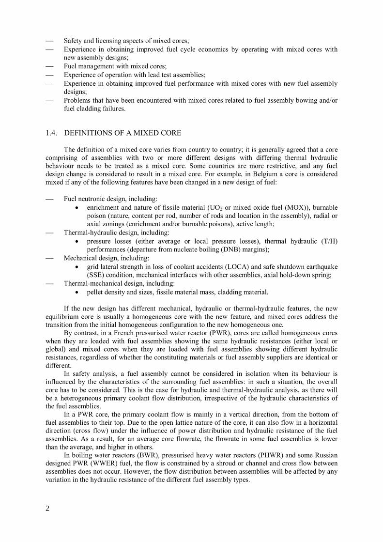
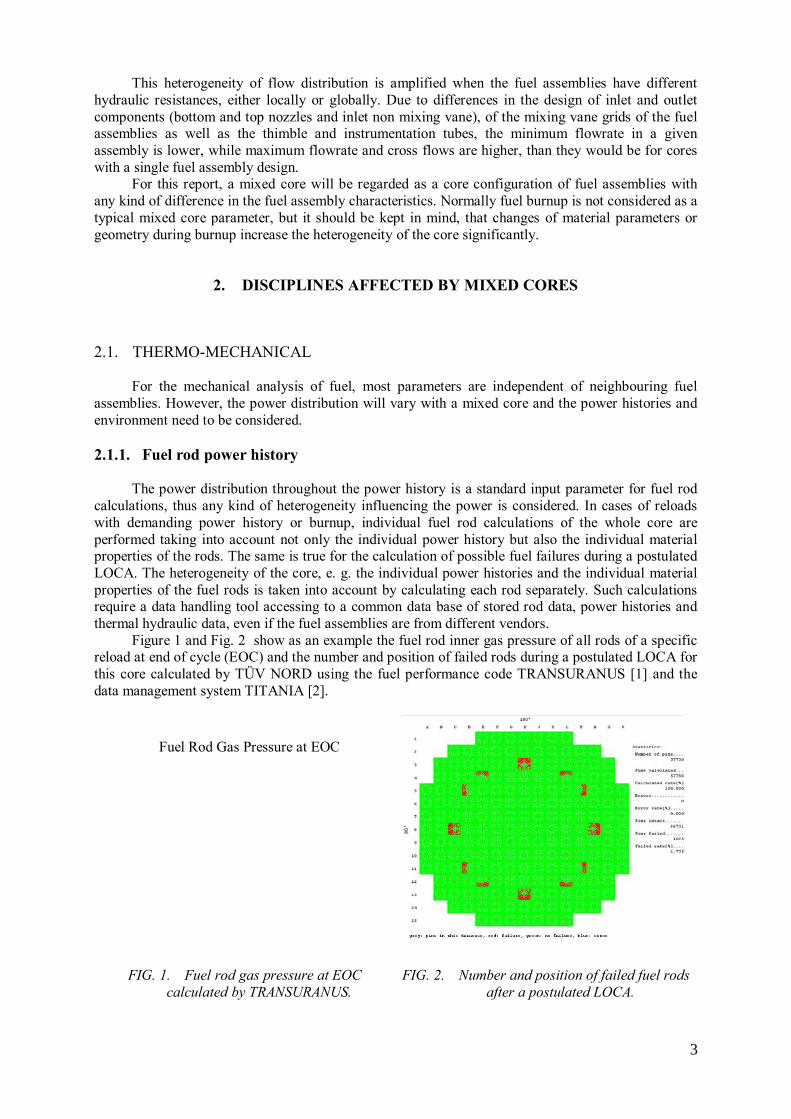
Figure 1 and Fig. 2 show as an example the fuel rod inner gas pressure of all rods of a specific reload at end of cycle (EOC) and the number and position of failed rods during a postulated LOCA for this core calculated by TÜV NORD using the fuel performance code TRANSURANUS [1] and the data management system TITANIA [2].
FIG. 1. Fuel rod gas pressure at EOC
calculated by TRANSURANUS.
FIG. 2. Number and position of failed fuel rods
after a postulated LOCA.
Fuel Rod Gas Pressure at EOC
3

2.1.2. Primary water chemistry The primary water chemistry is designed to ensure that both the fuel and plant can operate in a
reliable, economic and safe manner. In PWRs and WWERs the control of reactivity is carried out through boron dilution of the coolant and the pH is maintained through the addition of lithium (PWR) or potassium (WWER). In BWR plants, additions of zinc or noble metal can be made to the coolant to help control corrosion. Different water chemistry regimes are possible (e.g. Fig. 3, [3]) and these can affect the oxidation and deposition behaviour of differing fuel assembly types. The choice of a water chemistry regime will depend on the whole core operating parameters, for example peak power or cycle length, as well as the fuel rod cladding and its susceptibility to corrosion. This in turn can be influenced by the differing fuel types in a mixed core.
(a) (b)
FIG. 3. Standard and modified primary water chemistry for two NPPs (a) PWR and (b) WWER-1000
[3].
2.2. NEUTRONICS
2.2.1. Moderation ratio The ratio of fuel to moderator is an important parameter for core and fuel assembly design.
Differing designs of rod pitch or diameter will affect the moderation and the flux can be distorted when two types of assemblies (or bundles for a PHWR) are adjacent to each other.
Due to the design of BWR fuel, with the shroud acting as a coolant channel, there is much more flexibility to adjust the fuel to moderator ratio than there is with an open fuel assembly lattice as in a PWR. There have been significant changes in BWR fuel design, with many plants transitioning from 8 × 8 fuel arrays to 9 × 9 and 10 × 10 and including part length rods and variable enrichments. To further support the use of mixed cores, fuel is designed to be flexible in the discharge burnup to allow plant flexibility [4].
2.2.2. Heterogeneity
A fuel assembly does not need to contain rods of a single enrichment and an initial core and
subsequent reloads do not use assemblies that all have the same average enrichment. Calculations of the neutronics of a core need to be able to take into account the detailed composition of the assemblies and, in turn, will inform designers of improvements that may be possible.
Specific heterogeneities that can exist include axial fuel blankets which use lower enrichment fuel pellets at the ends of a fuel rod to reduce flux end peaking effects and improve fuel efficiency. Assemblies and bundles can be designed with variable enrichments between the rods or elements to
4

flatten the flux distribution and the whole core can be designed to have a low leakage through specific loading patterns of used and new fuel.
Heterogeneities that could affect a mixed core include:
Change in the feed enrichment; First introduction of axial blankets may lead to power peaking in adjacent assemblies; MOX fuel creates strong spectrum transition which has to be adequately treated; Some burnable absorber configuration may induce power distributions in adjacent assemblies
(for example gadolinia rods in peripheral positions of the assembly); Change in the instrumentation tube composition or geometry that could affect the response of
the in-core fission chamber.
2.2.3. Fuel enrichment Currently there is an effective maximum level of enrichment, 5% 235U used in power reactor
fuel. Early designs used lower enrichments, but as average burnup has increased in all LWR types of plant, the average enrichment of new fuel loaded into most reactors worldwide has increased to above 4% 235U. Slightly enriched uranium (SEU) is being introduced in to some PHWR plant to increase burnup significantly and depleted uranium is used for flux flattening.
2.2.4. Burnable absorber
Many different types of burnable poison absorbers are used to reduce the reactivity of a new
fuel assembly in the core at the start of its life. Gadolinium can be used as an additive in the matrix of the fuel pellet at differing concentrations or boron can be used either as a fuel coating or included in a removable core component. The neutronic consequences of the burnout of the absorbers need to be appropriately modelled.
Attention should be drawn on the fact that the strong local flux gradient that results from the presence of a fuel rod with burnable poison may have an impact on the uncertainty of a local in-core detector.
2.2.5. Active length Variations in the fuel stack length can increase the fuel loading in a reactor and hence cycle
length. Ref. [5] shows an example of migration to a longer stack length for WWER-1000 fuel and Fig. 4, shows how the initial loadings of the new fuel design utilised low enriched pellets at the ends of the rods to maintain an acceptable flux profile. Fully enriched pellets at the rod ends were only used in the third cycle of the transition when the whole core had transitioned to the longer fuel stack.
FIG. 4. Migration from TVS-2 to TVS-2M with longer fuel stack through 5 cycles of operation at a
WWER-1000 NPP, utilising low enriched pellets at the rod ends for the initial loadings [5].
5

2.2.6. MOX / RepU / Th MOX and reprocessed uranium contain different fissile and poison isotopes compared with
standard UO2 fuel types. The plutonium in MOX has differing quantities of fissile, fertile and poison isotopes depending on its origin and RepU contains varying amounts of the 234U and 236U isotopes. The neutronic effects of these materials need to be accurately accounted for in the design of both the assembly and full core. Thorium is not currently used in power reactors except some PHWRs where it is used as a seed material.
2.2.7. Uncertainties
2.2.7.1. Nuclear data
Evaluated nuclear data are continuously being improved. Recently, the European library was
updated to JEFF-3.1.1 [6], the American library to ENDF/B VII.1 [7], and the Japanese library to JENDL-4.0 [8]. These library improvements are performed on the basis of the newest evaluations of differential experiments. Along with this, growing attention is paid to uncertainty and sensitivity studies concerning the nuclear data evaluations, accompanied by improvements in the covariance data files describing the uncertainties of nuclear cross section data, and the calculational methods using these covariance data.
For the validation of the nuclear data libraries, a large number of integral experiments are used. Descriptions of such experiments are found in the International Handbook of Evaluated Criticality Safety Benchmark Experiments [9]. Most of these validation calculations refer to multiplication factors, although other measured quantities like reaction rates and reactivity coefficients are increasingly considered; such experiments are described in the International Handbook of Evaluated Reactor Physics Benchmark Experiments [10]. Most systems considered are compact assemblies, mainly at room temperature. Likewise, uncertainty and sensitivity investigations based on covariance data, as performed, e.g., with the TSUNAMI code package [11], primarily consider the multiplication factors of critical assemblies. Such compact critical systems at low temperatures are not necessarily representative for power reactors at operating conditions.
An example of the potential impact of these nuclear data uncertainties is seen in the systematic investigation on the results of calculations for large reactors, where uncertainty analyses were performed. In this case, the cross section uncertainty and sensitivity analysis (XSUSA) sequence was implemented. This has recently been developed as an extension of the software for uncertainty and sensitivity analysis package (SUSA) [12] for use with nuclear covariance data. The new method has been checked against TSUNAMI results for pin cell calculations and shown to be satisfactory for small scale investigations.
Results of this XSUSA application to full scale 2-D calculations for an LWR mixed core, specified within international OECD/NEA calculation benchmarks [13]-, are shown in Fig. 5. This result is for a WWER core in the uncontrolled state at hot zero power condition, loaded with UO2 and MOX fuel assemblies containing high quality plutonium in various burn-up states.
6

FIG. 5. Radial fission rate distribution for a WWER MOX core (averaged over all fuel assemblies
belonging to the same radial column).
The calculated multiplication factors lie in a band with a relative standard deviation of 0.71%, a
value which is expected for U/Pu LWR systems. For the radial fission rate distributions, however, a much larger influence of the nuclear data variations on the result is observed. This is shown in Fig. 5, where the reference values and standard deviations are displayed. The resulting standard deviations in the core centre are unexpectedly high. Investigations on a simplified core model [14] have shown that the differences in the fission rate distributions are mainly due to the uncertainties in the average number of neutrons per fission of 239Pu, and the particularly non-uniform distribution of UO2 and MOX fuel assemblies in the considered core, along with the high amount of 239Pu in the isotopic composition.
2.2.7.2. In-core measurement
It is necessary to confirm that a core is operating in the manner that it is expected and predicted
to do. To ensure this, in-core measurements of neutron flux are made to determine the local power. The necessary hardware and software are usually initially supplied by the reactor vendor, but it may be necessary to upgrade either to support a new fuel design or vendor.
In the case of a mixed core it is necessary to confirm that the methodology is also appropriate. An example arose in the BWRs at Tarapur where MOX fuel was introduced. The power distribution in each fuel assembly was measured using traveling in-core probes (TIP). The TIP readings are converted to relative powers in fuel assemblies by multiplying by two factors, C and J which are dependent on presence/absence of a control blade and voidage and burnup in the fuel assemblies.
When MOX fuel was introduced, the estimated values of the MOX assembly power, interpreted from TIP reading, were found to be significantly higher than the values calculated using the BWR simulator code COMETG.
The possible reasons for high measured heat flux were discussed in Ref. [15]. The various possibilities considered were:
0.0
0.2
0.4
0.6
0.8
1.0
1.2
1.4
1.6
0 1 2 3 4 5 6 7 8 9
Fis
sio
n R
ate
Fuel Assembly
average + 2sigma
average – 2sigma
reference
7
Erroneous TIP reading; Incorrect reading caused by sensitivity of TIP to variation in water gap thickness and detector
positioning; Possible mix-up of enrichments during fabrication.
Since the TIP behaviour showed consistency and stability and adequate care was taken during
MOX fuel fabrication the above reasons were eliminated. It was therefore decided to re-examine the procedure of interpretation of TIP readings to infer bundle power and heat flux.
The situation was resolved by no longer assuming infinite arrays of assemblies, but noting the local conditions of a MOX assembly surrounded by UO2 assemblies. A new C* factor was proposed in addition to the C and J factors. This factor essentially accounts for the sharp thermal flux gradients prevailing across a MOX-LEU interface. The estimation of the C* factors using the square lattice analysis code, SUPERB helped the resolution of this MOX power peak anomaly. C* values can also be obtained using Monte Carlo methods.
2.2.8. Peaking factors
The peaking factor is a key parameter for nuclear safety. The location of the maximum power
seen locally within the core will vary throughout the cycle and this information is important for fault and transient studies. The core design will determine the maximum peaking factor and is dependent on the types of available assemblies, including part-burnt assemblies, and the requirements for energy generation for the cycle. Good core design can minimise peaking factors and reduce the sensitivity of the core to fuel failure during transients and faults.
2.3. THERMAL HYDRAULIC ASPECTS The following discussion is specific to PWRs and is generally applicable to WWER-1000 plants
as well, as for BWR, PHWR and WWER-440 systems, where the assembler coolant flow is contained within a channel, the thermal hydraulic concerns are less important.
2.3.1. Fuel assembly thermal-hydraulic design bases:
The primary thermal-hydraulic design requirement for the fuel assembly is that fuel rod
integrity shall be maintained during normal operation and anticipated operational occurrences (AOO). Specifically, AOOs must not result in fuel failures or loss of functional capability. This requirement is conservatively satisfied by imposing the following thermal-hydraulic design criteria: the limiting fuel rod in the core must not experience DNB. In particular, the probability of avoiding DNB must exceed 95% with 95% confidence.
The new fuel assembly must meet all the thermal-hydraulic performance requirements and not limit the power capability of the plant; it must be compatible, from a thermal-hydraulic point of view, with all the other fuel assemblies susceptible to be loaded into the core. To this end, a number of criteria have been defined:
The overall hydraulic resistance of the new element should be comparable to that of the existing
fuel assembly and should not prevent operation at 100% of rated thermal design flow. Any change in fuel assembly hydraulic resistance with respect to the current or reference fuel assembly design in excess of a few percent will affect the reactor coolant system flow. The relative fuel assembly component loss coefficients for the different fuel assemblies present
in the core are calculated and compared. The new fuel assembly must not increase core by-pass flow beyond the allowable limit.
The fuel assembly shall be protected against lift-off under normal operation and AOO, with the
exception of the turbine over-speed transient associated with a loss of external load. Under
8

turbine over-speed transient conditions fuel assembly lift-off is permitted; however, no damage to the hold-down springs shall occur which would impair their continued use after the transient. Such lift-off must also be limited so that contact between bottom nozzle and the lower core plate guide pins is always maintained. The lift forces are calculated at hot full power, hot pump over-speed and at cold zero power
conditions. It is necessary to demonstrate that the hold-down spring force is adequate under these conditions.
2.3.2. Full core analysis – Transient cores analysis
In mixed cores containing different fuel types, localized hydraulic resistance mismatches may
cause local flow redistribution which can degrade the heat transfer capability and result in localized DNB penalties which could in turn limit power capability.
Redistribution of flow occurs generally because of thermal-hydraulic fluid condition gradients within the core. In a mixed core, with assemblies having different hydraulic resistance, these local differences are a mechanism that can cause flow redistribution. This redistribution results in the fluid velocity vector having a lateral component as well as the dominant axial component. The lateral component is commonly referred to as cross flow. The cross flow induced by local hydraulic resistance differences will impact the safety analyses of the core, and more particularly the DNB because the flow redistribution affects both mass velocity and enthalpy distributions.
In order to verify the thermal-hydraulic behaviour of the new fuel assembly in a full core configuration and to justify its compatibility with respect to the currently fuel loaded into the core, a CHF correlation is used and, generally, a statistical method is applied with the rod bow effect taken into account. Statistical methods combine the uncertainties on selected parameters and to derive the design limit DNBR to which the required margins and penalties are applied in order to reach the DNBRSAL. The selected parameters can then be taken at their nominal value for safety calculations.
With the DNBRSAL value, the core thermal limits for the new fuel are generated and it is verified that these limits are bounded by the core limits of the plant. The core thermal limits exist for the reference core. They have been constructed by making an envelope of the core exit saturation and DNB limit curve in the inlet temperature versus power diagram for each pressure. A similar approach must be followed for the new core. The comparison between the two sets of core thermal limits shows a whether there is a positive margin for the new fuel and if so where the lowest margin is, if not, the corresponding DNB penalty should be applied. If necessary, where this penalty is significant, the core thermal limits corresponding to the new core could be implemented on the site, but this requires a lot of additional verification. Fig. 6 gives a typical example of this approach.
9

FIG. 6. Core thermal limits for the new fuel (solid lines) and core thermal limits for the reference fuel (dashed lines).
DNB calculations are used to model core configurations with different quantities of new fuel in
the core and to determine the impact on the minimum DNBR of the homogeneous core. The resulting transition core DNBR penalty is obtained as a function of the number of the penalizing type assemblies. If there is no spare margin during the transition, this penalty can be offset by a trade-off between the DNBR penalty and the penalizing type fuel assembly F∆H limit.
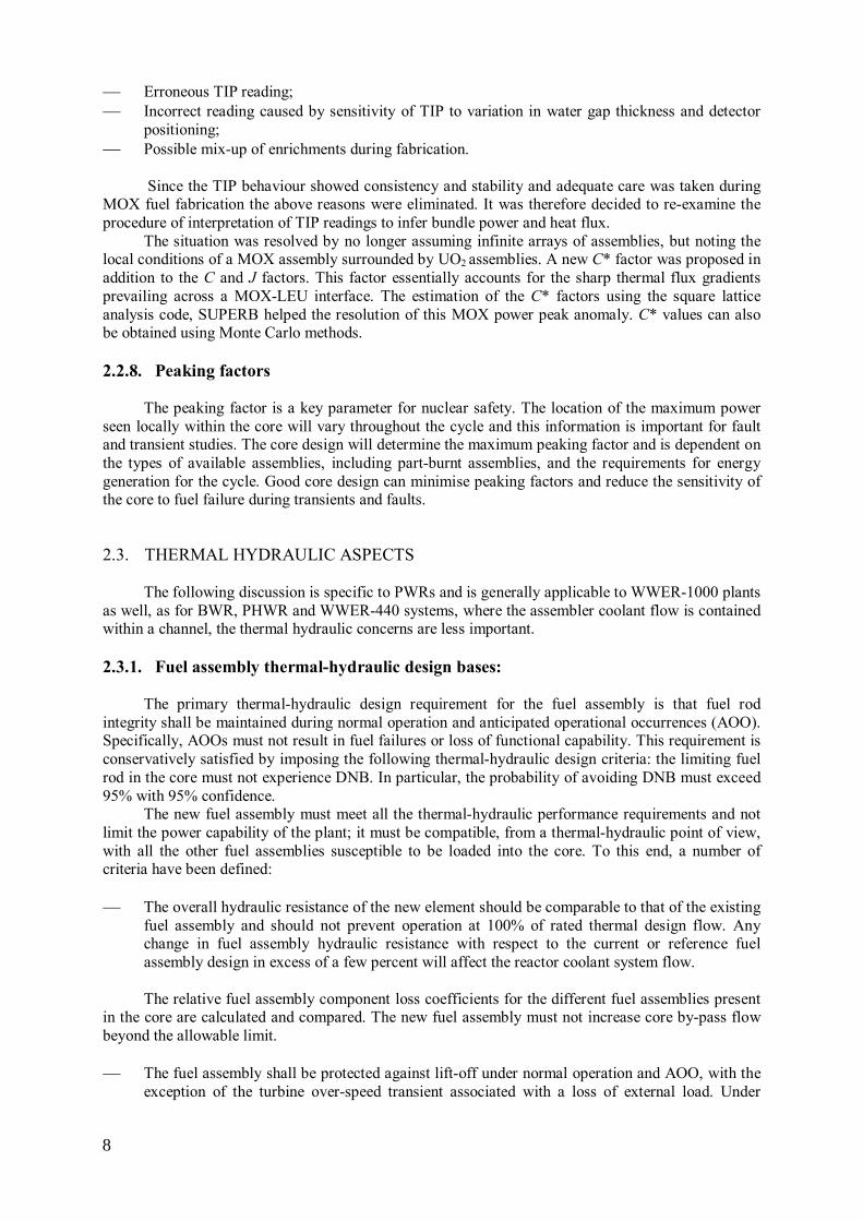
An example of this approach, the situation in Belgian reactors is shown in Table 1. This table shows the wide range of mixed core types that have been analysed, showing the different vendors and the various correlations and methods used.
10
TABLE 1. MIXED CORE THERMAL HYDRAULIC CALCULATIONS FOR BELGIAN REACTORS
Power Plant
Cycle Fuel Provider Fuel Type Co-resident fuels CHF Correlation / DNB code
Statistical Method
Doel 1 38 AREVA 14x14 AGORA-4H
HTP HTP/ COBRA3-CP
SSTDP
Doel 2 37 AREVA 14x14 AGORA-4H
HTP HTP/ COBRA3-CP
SSTDP
Doel 3 30 AREVA 17x17 AGORA-7A
FOCUS FC 98 / FLICA III-F
MSG
Doel 4 25 ENUSA 17x17 RFA-2 XLR
MAEF-4.2-XLR MAEF-3.1-XLR
WRB-1 / THINC-IV
RTDP
Tihange 1 29 AREVA 15x15 AGORA-5A
AFA-3G WRB1 / FLICA III-F
MSG
Tihange 2 24 AREVA 17x17 AGORA-7A
AFSU FC 98 / FLICA III-F
MSG
Tihange 3 21 ENUSA 17x17 RFA-2 XLR
AFA-3GLB-AA AFA-3GLB AFA-XR1
WRB-1 (WRB-2M) / THINC-IV
RTDP
2.4. FUEL MECHANICAL ASPECTS
2.4.1. Assembly/channel bow
2.4.1.1. Pressure drop difference The variation in pressure drop between differing assembly types will give rise to differing lift
forces from the coolant flow and hence the need to properly design the hold-down springs to balance this lift force. With a change in core the pressure drop in an assembly can also change with time as the numbers of different assemblies varies from cycle to cycle. There is a potential for the spring force to be high and cause the assembly to bow under the action of this force. Core wide assessment of the balance of forces resulting from flow redistribution is required.
2.4.1.2. Cross flow
A further force tending to cause assembly bow can arise from the cross-flow in PWR mixed
cores. Where the flow resistance between assembly types can reach up to 15%, there can be significant cross-flow and if the assembly is designed not to withstand such forces, bow may develop.
2.4.2. Fuel rod and spacer grid vibrational behaviour
The evaluation of the potential for fuel rod failure from grid to rod fretting is very complex. It
is required to know the vibrational response of the fuel assembly, rods and grids and their variation with burnup as well as the forces inducing any vibration and fretting wear.
2.4.2.1. Evaluation of fuel rod vibration
One such method of evaluating fretting wear, developed in Japan, is based on the model in Fig.
7, which was developed after performing several analyses of coolant flow around fuel rods. In particular, it was developed to analyze the fuel rod vibration caused by such flow. Flow tests and vibration analyses have also been performed. The method is described in some detail to demonstrate
11
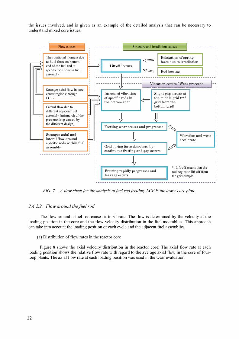
the issues involved, and is given as an example of the detailed analysis that can be necessary to understand mixed core issues.
Rod bowing
The rotational moment due to fluid force on bottom end of the fuel rod at specific positions in fuel assembly
Lift-off * occurs
Fretting wear occurs and progresses
Grid spring force decreases by continuous fretting and gap occurs
Vibration and wear accelerate
Fretting rapidly progresses and leakage occurs
Lateral flow due to different adjacent fuel assembly (mismatch of the pressure drop caused by the different design)
Stronger axial and lateral flow around specific rods within fuel assembly
Vibration occurs / Wear proceeds
*: Lift-off means that the rod begins to lift off from the grid dimple.
Flow causes Structure and irradiation causes
Stronger axial flow in core center region (through LCP)
Increased vibration of specific rods in the bottom span
Slight gap occurs at the middle grid (2nd grid from the bottom grid)
Relaxation of spring force due to irradiation
FIG. 7. A flow-sheet for the analysis of fuel rod fretting. LCP is the lower core plate.
2.4.2.2. Flow around the fuel rod The flow around a fuel rod causes it to vibrate. The flow is determined by the velocity at the
loading position in the core and the flow velocity distribution in the fuel assemblies. This approach can take into account the loading position of each cycle and the adjacent fuel assemblies.
(a) Distribution of flow rates in the reactor core
Figure 8 shows the axial velocity distribution in the reactor core. The axial flow rate at each
loading position shows the relative flow rate with regard to the average axial flow in the core of four-loop plants. The axial flow rate at each loading position was used in the wear evaluation.
12

FIG. 8. Distribution of axial flow rate in the core (core inlet).
(b) Distribution of flow rates in fuel assembly The flow in a fuel assembly around the bottom nozzle was evaluated in a computational fluid
dynamics (CFD) simulation. Two patterns were simulated: a fuel assembly next to a different type of fuel assembly, and a fuel assembly surrounded by different types of fuel assemblies (L-shape).
Figure 9 shows an example of the evaluation results. The output of the CFD analysis gives the axial and lateral flow rates at each grid cell. Here, CFD assumes a uniform flow below the LCP at 5 m/sec. The flow distribution in an assembly was assumed to be unaffected by the mean flow rate into it. Both the axial and lateral flow rates per grid cell were corrected by presuming a linear correlation. It was assumed that the relation between the output of the calculation and the inlet flow rate is linear. The axial and lateral flow rates in an assembly at the core location were obtained for different inlet flow conditions by using a linear correction. The conditions of the simulation are listed below:
Average velocity (bundles): 5 m/sec. The-adjacency condition: fuel assembly surrounded by
different type of fuel assemblies; Boundary conditions: 1/4 model, all boundaries periodic; Temperature: room temperature; Pressure: atmospheric pressure.
13
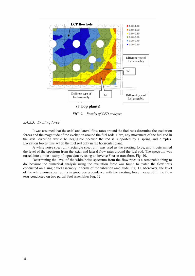
FIG. 9. Results of CFD analysis.
2.4.2.3. Exciting force
It was assumed that the axial and lateral flow rates around the fuel rods determine the excitation
forces and the magnitude of the excitation around the fuel rods. Here, any movement of the fuel rod in the axial direction would be negligible because the rod is supported by a spring and dimples. Excitation forces thus act on the fuel rod only in the horizontal plane.
A white noise spectrum (rectangle spectrum) was used as the exciting force, and it determined the level of the spectrum from the axial and lateral flow rates around the fuel rod. The spectrum was turned into a time history of input data by using an inverse Fourier transform, Fig. 10.
Determining the level of the white noise spectrum from the flow rates is a reasonable thing to do, because the numerical analysis using the excitation force was found to match the flow tests conducted on a single fuel assembly in terms of the vibration amplitude, Fig. 11. Moreover, the level of the white noise spectrum is in good correspondence with the exciting force measured in the flow tests conducted on two partial fuel assemblies Fig. 12
Different type of fuel assembly
Different type of fuel assembly
Different type of fuel assembly
LCP flow hole
(3 loop plants)
3-3
3-2
14

FIG. 10. Exciting force.
FIG. 11. Comparison of fuel rod vibration
amplitudes.
FIG. 12. Comparison of exciting forces at the bottom end of fuel rod (Bundle average flow rate:
5.5 m/s).
Determine the level of spectrum by the axial and lateral flow rate
Frequency
Inverse Fourier
Time
Exc
iting
for
ce
0
Axial flow rate
Lateral flow rate
Exc
iting
for
ce (
PSD
)
15

2.4.2.4. Support of the fuel rods The amount of fretting wear depends on the support given to the fuel rods. The relaxation of the
spring force at the bottom grid is relatively small due to low neutron fluence, so the grid spring force remains large enough at the end of life of fuel assemblies.
However, for a conservative evaluation, the lift-off condition at the bottom grid was assumed to occur after a specific burnup experience.
2.4.2.5. Vibration analysis of fuel rod
A time history analysis of fuel rod vibration was performed and the work rate can be calculated
at the dimple/spring from a vibration analysis of the fuel rod. The work rate is obtained by multiplying the contact force of the fuel rod on the dimple/spring and tangential relative speed (sliding speed) between the rod and dimple/spring. The contact force is the spring force calculated from the displacement of the fuel rod over a certain time.
The sliding speed is the relative slip velocity between the fuel rod and the dimple/spring. Here, the friction between the fuel rod and the dimple/spring is considered. When the frictional force is large enough, a relative slip cannot occur, and the work rate remains zero. However, because of the relaxation of the spring force, the friction on the rod and grid surface can no longer resist the fuel rod’s movement and a relative slip will begin at a certain fluence condition.
The vibration analysis model was applied to the case of a gadolinia doped fuel rod, where the rod diameter was a little smaller than a standard rod and it was possible to predict that the wear rate was sufficient to account for the observed fretting failure.
2.4.3. Change in the number of mid span mixing grids or spacer grids
Changes in the number of grids on an assembly will significantly alter the thermal hydraulic
resistance. This will result in cross-flow and variations in the flow through an assembly, and it is possible to induce flow starvation if the flow resistance is much higher than adjacent assemblies. Further this will affect the lateral forces on assemblies in a PWR with the potential to cause bowing. Generally the effect of the additional flow mixing due to the mixing grids is sufficient to maintain the DNBR for the fuel.
2.4.4. Grid lateral stiffness for LOCA and SSE
The grid stiffness affects the lateral vibration modes of an assembly and therefore its response to
a LOCA or SSE event. The effect of differing assemblies has to be addressed both on an individual level and also in combination with the response of adjacent assemblies of either the same or a different type. It is necessary to demonstrate that grid crushing does not occur in LOCA or SSE events in a manner that prevents the insertion of control assemblies.
2.4.5. Hold down force
The hold down force on an assembly is designed to ensure that the assembly remains seated on
the bottom plate of the reactor under all transient conditions, with the exception of the pump over-speed transient. It is also necessary to ensure that the spring force is not so great that the assembly is forced to bow under the axial load.
2.4.6. Control rod drop time
The requirements on control rods include their ability to respond rapidly enough to ensure safe
shutdown of the reactor when required. This ability can be compromised when an assembly loses its straight axial profile and it is possible for control rods to be delayed in reaching their final location due to friction between the control rod and the bowed thimble tubes. In extreme cases it is possible for the control rod to become stuck inside the assembly and fail to insert completely in what is known as an
16
incomplete rod insertion (IRI) event. Where this is a possibility operators may be asked by their regulator to make regular tests of the control rod drop time and to only use fresh assemblies in control rod locations as such assemblies are least likely to bow during a fuel cycle.
2.4.7. Rod and assembly growth
Rod growth is caused by axial irradiation growth of the fuel stack and needs to be limited in
extent so that the fuel rod does not interfere with the top and bottom nozzles, with the potential for rod bow and distortion, potentially leading to power anomalies where the distances between rods are affected.
2.4.8. Potential feedback on design
The introduction of a new fuel design requires a full calculation of the behaviour of the fuel and
core throughout the entire dwell of the fuel, including transient conditions. This can lead to situations where it is necessary to amend the design of the new fuel in a manner that ensures that appropriate safety margins are maintained. Such a design change can either be as a result of an interaction with the existing fuel type or a response to a change in methodology. It is possible that the old fuel type is not sufficiently robust to be in the same core as an advanced assembly design working at its full potential. An example can be the requirement to add plenum volume to a rod to ensure that fission gas release does not cause sufficient internal pressure to threaten rod integrity in transient conditions.
3. JUSTIFICATION OF MIXED CORES
3.1. COUNTRY SPECIFIC LICENSING APPROACH
3.1.1. Argentina
3.1.1.1. General safety and operational requirements The key safety and operational requirements considered mandatory by the Argentinian safety
authorities, NA-SA, for the project to increase enrichment at Atucha-1 and for the subsequent operation with mixed cores were:
Atucha-1 fuel performance should not be adversely affected; Fuel design safety margins for the new fuel using SEU should be kept as close as possible to the
margins for natural uranium fuel; The reduction of the operational flexibility at the power plant must be as low as possible.
3.1.1.2. SEU effect on fuel performance
The main fuel operating parameters affected by the increased enrichment were:
Discharge burnup; Residence time; Local burnup at the time of fuel reshuffling (power ramps); Maximum burnup at high power.
Power levels, water chemistry and sheath and coolant temperatures were not significantly
affected.
17

Therefore the aspects of Atucha-1 fuel performance considered were those mainly affected by the higher burnup and by the increase in the residence time. The most relevant were:
Fission gas release and its impact on internal gas pressure; Fuel cladding creep down and sheath strain; Relative length changes between the fuel stack and the cladding and between fuel rods at
different positions of the fuel assembly; Fuel cladding axial growth; Fuel assembly structural integrity including:
o effectiveness of the interaction between fuel rods and spacer grids; o effectiveness of the interaction between elastic sliding shoes and coolant channel to hold
fuel rods and fuel assemblies in their positions throughout the whole irradiation; Power ramp behaviour; Waterside corrosion and deuterium uptake.
3.1.1.3. Fuel design verification
Several analyses were performed to fulfil regulatory requirements and to update the safety
analysis report. Fuel rod calculations were performed to evaluate the fuel performance in the new operating conditions with a code that is used as a routine tool in the design of fuel rods for PHWR and PWR. Conservative design parameters were used as input data and conservative power histories were also selected according to the parameter to be verified. The main objective of these calculations was to demonstrate that fuel performance safety margins are not affected by the utilization of SEU.
Several power histories representative of different new irradiation routes were analyzed. The main performance parameters included in the fuel rod calculations were:
Maximum fuel temperature; Internal fuel rod pressure; Long term sheath strain; Short term strains; Waterside corrosion and deuterium pick-up; Fuel rod axial growth; Relative elongations of the pellets stack and the cladding; Relative elongations between fuel rods at different positions of the fuel assembly.
3.1.1.4. Fuel related limits leading to operational changes
Power ramps are produced during irradiation as a result of fuel reshuffling, fresh fuel loading,
reactor start-ups and reactor power changes and their associated control rod movements. Power ramps can cause fuel failures associated with pellet clad interaction (PCI) and stress corrosion cracking (SCC). The PCI prevention criteria were reviewed by CNEA and a new set of recommendations was defined for SEU operation at higher burnups. The new criteria are based on the combination of linear power before and after the ramp and the burnup at the time of the ramp. They also included considerations of the maximum ramps allowed without limitations and a maximum allowable power ramp rate. The operator of the power station translated these criteria into operational instructions which refer to data obtained from the fuel management calculations. As a result of the new criteria the time taken to reach full power in a plant start-up increased from 28-35 hours.
Figure 13 shows the power ramps as a function of the local burnup during the implementation of the program. The distribution of power ramps shows the application of the burnup dependent criteria.
18

FIG. 13. Power ramps in Atucha 1 as a function of burnup, showing the limitation of maximum uprate
with burnup.
3.1.2. Belgium
3.1.2.1. Belgian safety requirements No fundamental modifications of methods or models are needed to treat mixed cores;
nevertheless some Belgian safety requirements should be applied when performing the appropriate calculations which are also required for homogeneous cores. They are summarized:
The original methods statistically combined the uncertainties on the core flow rate and the by-
pass flow rate. These parameters do not statistically fluctuate as a function of time for a given plant. Therefore, the associated uncertainties arise only from the inaccuracy of the measurements and according to the Belgian regulator, Bel V, may not be statistically combined. They have to be considered in a deterministic and penalizing way. At the request of Bel V, these two parameters were thus removed from the statistical
combination by the manufacturers when applying statistical methodology in Belgium.
The most recent methods include, in the statistical combination, the uncertainty of the DNB correlation. This releases an important DNB margin and correspondingly reduces the conservatisms. In a philosophy of “defence in depth”, safety margins are useful to cover unknown phenomena, application of statistical methods, incomplete demonstrations or other issues. A full reduction of the conservatisms was not acceptable to Bel V and a 4% generic margin on
the design limit departure from nucleate boiling ratio (DNBR) has been imposed.
The statistical combination of the DNB correlation uncertainty distribution is not without concern. Indeed, when a DNB correlation is used for a particular type of fuel assembly, most often the associated data base contains data subsets corresponding to this specific fuel. The uncertainty distribution of critical heat flux data for a subset might be different from the uncertainty distribution of the whole correlation, thus introducing a bias. Rigorously, such a bias cannot be accepted: the statistical combination process for a non-uniform, biased sub-population would be mathematically wrong. However, from a safety point of view, if the bias is in a
19

conservative sense, – i.e. the mean value of the sub-population is higher than the mean value of the correlation and the standard deviation lower – then the approach may be accepted. Moreover, as more than one subset of data should be considered, the normal distribution of each set, the homogeneity of the sets and the normal distribution of the combined sets have to be demonstrated at a 5% rejection level.
All these verifications have to be performed by the fuel manufacturer.
The rod bow penalty has also to be taken into account in the determination of the safety analysis limit DNBR, DNBRSAL. Rod bow models have been licensed by Bel V for all the types of fuel present in Belgian cores and the DNB rod bow penalty was required to be applied on a deterministic way, i.e. as a multiplier on the design limit. In the past, the rod bow effect amounted to about 4% for most of the fuel types loaded in
Belgian cores, with a few exceptions relative to fuel length, number of grids or burn-up range. At that time, manufacturers using statistical methods applied a “provision” for rod bow of 6.5% so that the total penalty on the design limit DNBR amounted about 10% (6.5% + 4% generic margin (see second bullet point above)). Subsequently, for consistency, Bel V has imposed this order of magnitude of global penalty to all the manufacturers.
More recently, due to the experience feedback, rod bow models have been improved by almost all fuel manufacturers so that the corresponding DNB penalties have tended to decrease. The value of 6.5% has now become unnecessarily high and Bel V has accepted the application of the new calculated rod bow penalties on the condition of adding a 1.5% margin as “reserve”. Moreover, the burn-up range covered by the penalty has to be defined in the safety evaluation studies and it must be verified for each cycle so that, above the retained burn-up breakpoint, the power delivered by the fuel assemblies is low enough to prevent rod bow.
3.1.2.2. Nuclear compatibility (uranium and gadolinia fuel assemblies)
Relevant nuclear parameters such as reactivity, reactivity coefficients, control rod worth and
power density distribution are evaluated for different fuel assembly types. The nuclear compatibility evaluation is based on single fuel assembly calculations in an infinite medium.
The safety of a core is assured by assessing, for each cycle, the applicable design criteria and associated safety limits on a variety of nuclear parameters, the so called nuclear key safety parameters. These safety limits represent the link between nuclear design and safety analysis.
It is part of the design process for a given cycle to demonstrate that the applicable safety limits are met. In this way it is assured that the conclusions of the safety analysis are valid for the specific cycle in normal operation as well as in fault conditions.
The following calculations as a function of burn-up are performed:
Comparison of the fuel assembly reactivity at different operating conditions: hot full power (HFP), hot zero power (HZP) and cold zero power (CZP);
Comparison of the uranium and plutonium isotopic inventory; Comparison of the xenon and samarium reactivity worths; Comparison of the moderator temperature coefficient and Doppler power coefficient. Also, the
fuel resonance temperatures used as the basis for the Doppler coefficient calculations are compared;
Comparison of the prompt neutron lifetime and effective delayed neutron fractions; Comparison of the control rod reactivity worth; Quantification of the power distributions (rod-wise power distribution, relative assembly power
distribution, peak integrated rod power (F∆H)) impact of the presence of the new fuel assembly next on the adjacent old one.
20

3.1.2.3. LOCA SSE The mechanical design of the fuel assembly structure must satisfy the safety requirements for
the bounding Class IV events, i.e. LOCA and SSE. Control rod drop and core cooling must remain possible during and after such events. This is translated to criteria for the grid, guide tube and nozzle integrity. Concerning horizontal impact, the maximal impact force must remain smaller than the grid buckling limit.
3.1.3. Canada
The Canadian Nuclear Safety Commission (CNSC) was established in May 2000 under the
Nuclear Safety and Control Act, replacing the AECB which was founded in 1946. The CNSC regulatory requirement for implementation of the new fuel bundles is that “The licensee shall not load
any fuel bundle or fuel assembly into a reactor unless the use of the design of the fuel bundle or fuel
assembly has received prior written consent by the Commission, or a person authorized by the Commission.”
There have been two recent proposals to replace fuel bundles in CANDU reactors undertaken by Canadian utilities to replace the current CANDU 37-element fuel bundles (37R) with:
The CANFLEX-LVRF 43-element bundles (LVRF) – Bruce Power project; The modified 37-element bundles (37M) – Ontario Power and Gas and Bruce Power projects.
The aim of these projects is to improve safety margins; the CANFLEX bundle increases the
number of elements, whilst the modified 37 element bundle has a smaller diameter central element to improve coolant flow. Demonstration irradiations were carried out prior to full core implementation.
The Utilities requested the CNSC consent to use of the LVRF and 37M fuel bundles in the Bruce Power and Darlington reactors. To assess the safety risk associated with the conduct of the demonstration irradiations, CNSC reviewed the following topics:
Fuel thermal hydraulics; Safety analysis; Reactor physics and nuclear criticality safety; Fuel bundle manufacturing; Operational procedures; System interaction; Human factors.
CNSC review of two demonstration irradiation submissions for the LVRF and 37M fuel has
been performed. Detailed reviews were made of the thermal hydraulics and safety analysis, with particular interest in severe accident behaviour. To assure that the LVRF bundle is fully compatible with the 37-element bundle in mixed fuel bundle strings, experiments of pressure drop involving mixed junction were required and conducted. The introduction of new fuel designs for demonstration irradiation purposes was shown to have no negative impact on the current reactor licensing basis.
The demonstration irradiation for the LVRF fuel has been completed and the utilities are moving towards full-core implementation of the 37M bundles. To obtain CNSC authorization to proceed with the full-core implementation, the full-core and transitional-core safety cases need to be re-assessed.
3.1.4. France
The licensing approach in France has evolved with time as the type and prevalence of mixed
cores has increased. The original assumption was that mixed cores would be transition states as a plant transitioned from one fuel design to another.
At the beginning of nuclear power generation in France fuel assemblies were provided only by FRAMATOME (now AREVA). The initial standard fuel assemblies were replaced with an advanced
21
fuel assembly (AFA) design, which has been continually improved to a second and third generation design, AFA-2G and AFA-3G. These designs have had their own variants, each of them with its own hydraulic resistance. Since 1993 a second design, originating with Siemens (now part of AREVA) was introduced, the high thermal performance (HTP) design.
3.1.4.1. Mixed core safety analysis in 1996
In 1996, around 90% of the loaded fuel assemblies were AFA and the remaining 10% were
mainly HTP. Hydraulic and thermal-hydraulic compatibility was shown by checking that the mixed cores would not challenge safety analysis in the following areas:
With respect to large break LOCA, by evaluating the maximum clad temperature for an
expected mixed core. With respect to DNBR safety analysis, the DNBR penalties arising from mixed cores were
evaluated only for predicted transition cores (for instance, 1, 2 and 3 fuel reloads) and for category 1 and 2 events. These penalties were compensated by available margins with respect to the assumptions considered in the safety analysis report (SAR) for the evaluation of the minimum DNBR (such as the rod bow penalty).
With respect to fuel assembly hold-down force, the safety analysis would be carried out by checking that the balance of forces (assembly weight, spring force, hydraulic force, buoyancy) would remain above a minimum required margin considering the increased flowrate.
With respect to pin fretting wear it had been concluded that the impact of the differences of head losses between the fuel assembly designs was negligible, compared to the effect of expansion of the jets coming from the lower core plate.
With respect to minimum and maximum guide thimble and instrumentation tubes bypass flow, on the basis of the inside tubes diameters.
This analysis was considered appropriate as mixed cores would occur only for transition cycles,
the hydraulic resistances between the loadable fuel assemblies were similar and that while DNBR penalties would result from transition cores, they were low and would disappear once equilibrium cycle has been reached.
3.1.4.2. Mixed core safety analysis in 2004
By 2002 the proportion of the different fuel assembly designs in operation had not significantly
changed, but it was understood that this proportion would change in the future. This was mainly due to a new fuel vendor (Westinghouse), where higher DNBR penalties could be expected for their robust fuel assembly (RFA), and the presence of a wide range of loadable fuel assemblies that were stored at the plants. The number and the probability of occurrence of mixed cores had increased and the composition of mixed cores had been diversified.
Between 1996 and 2002 some changes had therefore been made in the evaluation of the impact of mixed cores on safety analysis with respect to:
large break LOCA safety analysis: the impact of mixed cores on the maximum clad temperature
could be evaluated: • For older fuel managements, at reload safety analysis for the as-loaded mixed core; • For newer fuel managements, with a generic analysis for cores made of fuel assemblies
with a range of hydraulic resistance. This analysis would be valid for a mixed core irrespective of the fuel assembly designs, as long as the hydraulic difference between the designs would be within this range.
DNB safety analysis: • For experimental RFA/AFA mixed cores, the RFA supplier evaluated the DNBR
penalties as a function of the proportion of the fuel assembly with the higher hydraulic resistance in the core and as a function of the assemblies disposition.
22

• Since all core configurations cannot be predicted, checking would be done at each reload to ensure that this analysis remained valid.
DNBR penalties would be compensated by the available margins with respect to some assumptions considered in the Safety Report for the evaluation of the minimum DNBR, such as rod bow penalty, thermal hydraulic flowrate or fuel pin power. In 2004 it was noted that the analysis was appropriate for the present mixed cores, but as mixed
cores would spread, an evolution of safety analysis would be required in the future in order to remain appropriate.
3.1.4.3. Mixed core safety analysis in 2011
Due to a policy of diversification of fuel supplies and with the ageing of the reactors, and hence
with the increased of the number of loadable fuel assembly designs, mixed cores have become common. In 2011 mixed cores were loaded in about 70% of the 58 French reactors, as shown in Fig. 14.
FIG. 14. Nuclear plants utilising mixed cores in France in 2011.
Five different fuel assembly designs have been loaded in the 900 MWe PWRs, six in the 1300
MWe PWRs, while only two designs have been loaded into the 1450 MWe PWRs. Most mixed cores are quite simple with 81% of them built from two designs of fuel assembly. However, some are more complex; 17% use three fuel assembly designs and 2% of mixed cores with four designs. It is no longer possible to define a typical mixed core.
Between 2003 and 2009 one change had been made in the evaluation of the impact of mixed cores on safety analysis with respect to DNBR: it is now necessary to use all available margins with respect to the assumptions considered in the Safety Report for the evaluation of the minimum DNBR to compensate the DNBR penalties. Previously only some of the margins were required.
In 2011 it was agreed that additional analysis was needed for mixed cores:
Regarding LOCA, analysis of impact of mixed cores on large break LOCA only was no longer sufficient and the evaluation of safety of mixed cores had to integrate intermediate break LOCA;
Regarding DNBR, analysis of impact of mixed cores on category 1 and 2 events was not sufficient and the evaluation of safety of mixed core had to consider category 3 and 4 events.
Homogeneous cores Mixed cores
23

Further, as cores considered in the SAR are supposed to reflect reality, mixed cores need to be
considered in transient analysis in the SAR in respect of DNBR analysis.
3.1.5. Germany Apart from the applicable regulatory codes and standards to be considered, the licensing
procedure in Germany distinguishes licensing steps and operational surveillance. Concerning the reactor core in most power plants, a so called “frame specification of the reactor core” is defined by the licence. This frame specification sets requirements on the hardware and a set of design criteria that must be fulfilled. Typical hardware specifications are the fuel material, the enrichment, the Gd-content or the 16 × 16 or 18 × 18 grid lattice. Typical design criteria are, for example, limits for stress, strain, corrosion, rod internal pressure and LOCA criteria for fuel rods and assemblies as well as criteria on criticality safety and reactivity coefficients for the nuclear core design.
Any fuel assembly design and any arrangement of the fuel assemblies in the core that fulfil this frame specification are allowed in principal. Therefore, any modification in the fuel assembly design or core configuration is covered by the licence provided this modification fits into the frame specification.
The conformity of the modification with the frame specification has to be proven by appropriate design analyses. For some minor modifications this may result only in an update of an already existing design report. In other cases, e.g. the first introduction of a new vendor, the full scope of safety documentation including design analysis, model validation, validation tests and qualification of manufacturing, has to be provided. Even in the case of a few lead assemblies, all relevant aspects have to be considered.
All analyses and documents related to the assemblies and to the projected core configuration are provided to the authority. Before the start-up of the new reactor cycle the documents are reviewed and the analyses are assessed by independent calculations from the consultant/TÜV as part of the regulator’s approval process.
This procedure allows the utilities to react flexibly to developments in fuel design. Only for major steps, which require an extension of the frame specification, is an amendment to the licence required, e.g. an increase of enrichment or the introduction of MOX fuel
Thus virtually all modifications of the fuel design (material, geometry and vendor) which have been introduced in the past were not licensing steps but part of the normal surveillance process.
3.1.6. Hungary
There is no separate licensing procedure for mixed cores. Mixed cores are supervised in two
types of licensing procedures:
Licensing of new fuels; Reload licensing.
Licensing documentation of new fuels shall contain all the information related to mixed cores
during the introduction of the new fuel including. This includes verification of the chemical and mechanical compatibility, new operational limits established by safety analyses, a revision of the fuel safety analysis report (FSAR), validation of the computer codes used for safety analyses, reload design and core monitoring, and a demonstration of the fulfilment of limitations during transient cores.
Reload licensing is involved in the start-up licensing procedure. Mixed cores are controlled in the standard manner. The basic documents checked and approved by the regulatory body are:
Reload design and safety reports; Cartograms of the refuelling; Operator’s manual; Calculations for start-up measurements.
24

There is no special inspection of mixed cores. The main tool for inspections is the VERONA in-core monitoring system which can monitor all of the parameters of the assemblies and stores the data with their accuracies and limitations individually (for each assembly) thus limit failures can be identified and displayed exactly. The regulatory body has on-line access to VERONA.
3.1.7. India
3.1.7.1. Safety review of mixed core loadings
Core characteristics are dependent on the fuel material used and the core loading pattern. Hence,
whenever there is a change in the core loading pattern, these core characteristics are studied in detail. While performing the safety review for licensing of any such fuel loading pattern with mixed fuel bundles, following aspects are reviewed to ensure the safety of reactor:
(a) Reactivity control
The capability of the shutdown system to render and hold the reactor subcritical by an adequate reactivity margin should be demonstrated for the most reactive core condition. This shall hold for the whole range of operating conditions and core configurations; and for anticipated operational occurrences and accident conditions;
Since PHWRs operate with the reactor regulating system on automatic control, it is essential to have a desirable reactivity worth in these devices so as to have a sufficient two-way reactivity control in an operating reactor.
(b) Reactivity coefficients
The temperature coefficients of fuel, coolant and moderator depend on the core loading pattern with natural uranium fuel. It is required that in the range of power operation, the combined effect of these coefficients should be negative with an increase in power;
Reactivity feedback from the temperature coefficient of fuel is ensured to be negative in all the temperature ranges during the complete spectrum of bundle burnups;
Since the void coefficient in PHWRs is positive, it is essential to ensure that the magnitude of the void coefficient does not increase with the change in loading pattern of reactor core.
(c) Reactor kinetics
Delayed neutron fraction, β, is checked to be within the specified range so as to be compatible
with the rates of negative reactivity insertion by the reactivity devices of the reactor regulating system and the reactor protective system.
(d) Flux distribution
Flux shape in the reactor core should be controlled to obtain the acceptable spatial distribution considering the limitations on bundle and channel power. Axial and radial flux should not have humps or depressions within the core. The fuel design of different types of bundles loaded should establish the limits on bundle power.
3.1.8. Russian Federation JSC TVEL is continuously working to improve WWER-1000 fuel performance. Design changes
have been implemented to increase the stiffness of the skeleton and the inventory of uranium in the core, to improve the thermal-hydraulic margin and introduce new zirconium alloys with improved performance. These new designs have different mechanical and/or hydraulic characteristics compared with to regular fuel and the question of justification and licensing of cores, containing fuel of different designs (mixed cores) arises.
25

The Russian regulatory body, Rostechnadzor, grants a utility a special licence for new fuel operation and to perform research and development activity on site. There are no prescribed requirements for mixed cores licensing established by Rostechnadzor, but there is a general requirement that the safety of a core reload must be demonstrated, regardless of the type of loaded fuel assemblies. This requirement forces the designer to perform a full scale core analysis, including transition cores leading to a full core load of new fuel. The issues to be discussed in analyses include:
Core physics design; Fuel assembly mechanical design; Fuel rod mechanical design; Impact on reactor internals; Core thermal-hydraulic design.
3.1.8.1. Safety analysis
All WWER-1000 reactors in Russia are supplied by fuel, developed by TVEL. This facilitates
the licensing process, as the same methods and analytical models are used for the analysis of the performance and safety of both homogeneous and mixed cores. TVEL has access to information on fuel performance and has been able to provide sufficient evidence to the regulatory body to justify the safety of mixed cores without any penalties on operational flexibility.
In addition to the regular scope of analyses, the designer plans and carries out tests or/and calculations in order to show compatibility of the new fuel with co-resident fuel according to his own criteria. Usually the scope of tests includes, but is not limited to, mechanical and thermal-hydraulic tests with components, models and full-scale mock-ups of fuel assembly. The information derived from these tests allows an estimate of the mechanical and hydraulic loads on core components and reactor internals, flow distribution through the core and the influence of a mixed core on design margins.
The designer of a new fuel type establishes the criteria for acceptance of mixed cores. In general they can be summarized as follows:
Mechanical:
• Fuel assembly bow, growth and twist within design limits. Hydraulic:
• Pressure drop difference less than 25% (total); • Lateral flow velocity less than 1 m/s.
Safety: • Sufficient margin to safety criteria is proved.
Operational: • No penalties on transition core design, exception may be done for the first transition
core.
The most important step in implementation of a new fuel design is a demonstration of predicted fuel performance through operation in a commercial reactor, in strict compliance with a developed and agreed lead test assembly (LTA) program. The LTA program prescribes the specific actions to be carried out on the test assemblies during operation and outages, and determines the scope of investigations and acceptance criteria.
3.1.9. Slovakia
A formal license is required for every type of fuel to be used in a NPP in Slovakia. The legal
basis for nuclear fuel licensing and operation is defined by the following documents:
Atomic Act No. 541/2004 Coll.; Regulation No. 430/2011 Coll.;
26

Safety Guide BNS III.4.1/2000 rev. 2010. The scope of documentation to be submitted depends on the nature and extent of the
modification of fuel. There are no special legal requirements regarding mixed cores. All fuel used in Slovakia has been supplied by a single vendor, TVEL. Since 2006 all units have been operating with mixed cores only. The driving forces for fuel type changes are an increased fuel economy and a reactor power uprate. No prototype fuel has been loaded in Slovakia, the requirement has been that previous experience is required and that usually several cycles of experience are needed. Exceptionally, a new fuel design was introduced in 2011 with the only prior experience being twelve months at Kola NPP in Russia.
A modification to the type of fuel is reflected in the licensing documentation, taking into account all aspects of using the fuel, throughout the whole life cycle, including:
FSAR (transient analysis, reactor, auxiliary systems, radioactive waste management, etc.); Transportation of fresh and spent fuel; Fresh and spent fuel storage; Operational procedures; Emergency planning zone; Insurance for civil liability for nuclear damage.
A new fuel type also requires extended start-up and power tests. In conclusion, a new fuel type is implemented using state of the art technology and in response
to utility requirements. No prototype fuel is allowed to be used in Slovak NPPs and so far all new fuel types were loaded gradually, i.e. mixed cores were used. This approach has not caused or indicated any safety challenges so far.
3.1.10. Sweden
3.1.10.1. Procedure
The process that the Swedish utility Vattenfall uses for the qualification of new fuel is initiated
after purchase of manufacturing services for lead fuel (typically 4 assemblies) or reload fuel (typically 4 reloads), which may include an option for pre-delivery of lead use assemblies (typically 4 assemblies). Following previous fuel bids, Vattenfall and the contracted vendors had a great amount of work qualifying purchased fuel of different designs. This situation was a strain for the organization and was also associated with project risks. Vattenfall’s modified strategy is therefore to take lead use assemblies for qualification of all potential reload designs before the fuel bid, and reduce the amount of work to be performed after the signing of the contracts as much as possible. This strategy is also in line with the requirement of the Swedish radiation safety authority (SSM) that there shall be at least a two-year lead fuel demonstration period before first reload.
In Vattenfall’s design review for qualification for new fuel it is verified that the requirements on fuel safety and functionality are fulfilled and that the fuel design documentation is sufficiently comprehensive and transparent. This work is performed in cooperation with the fuel vendor in what is commonly called a fuel “licensing” project.
The task of the fuel vendor is to support Vattenfall in presenting a complete and consistent safety case for the fuel, including mixed core transition cycles until full core operation is reached. The fuel vendor of the resident fuel is expected not to obstruct the new vendor in performing its task and should, to an acceptable extent, enable mixed core analysis by disclosure of relevant information and data.
The responsibility for safety rests entirely with the plant operation licensee, Ringhals nuclear power plant (NPP). Thus, when the documentation from the fuel licensing project is completed it must also undergo safety review at the plant. The documentation from the fuel licensing project and the safety review are then part of the notification of change in plant/new fuel design, that is sent by the licensee to SSM at least 3 months before the outage when the fuel will be loaded, for assessment. The task of SSM is supervisory – to ensure that the responsible party conducts its activities in accordance
27

with rules and regulations and in a comprehensive and adequate manner in order to ascertain safe operation of the plant.
3.1.10.2. Mixed core analyses by the fuel vendor
In the fuel licensing projects, mixed core considerations are first of all included in a survey of
fuel performance and general risk evaluation, based upon the information of fuel operating experience and other supporting design evaluation studies provided by the fuel vendor. This is called the extended technical review. It is a practice that has been introduced in order to show that the two-year lead fuel demonstration period, normally required by SSM before first reload, can be reduced when there is sufficient validation from similar reactors with similar operating conditions.
The extended technical review includes the fuel vendor’s operating experience of the fuel design in mixed cores. This information can be used to support verification of functional compatibility with the resident fuel and the plant. More specifically, the fuel vendor is expected to show that the fuel will not vibrate when introduced in a mixed core (or a homogeneous core), and that the involved fuel components are resistant to wear. This is typically shown through flow tests and then confirmed by fuel operating experience in homogeneous and mixed cores.
Furthermore, mixed core investigations are typically presented by the fuel vendor in geometrical and thermal-hydraulic compatibility reports. The purpose of the geometrical compatibility report is to show that the fuel is functionally compatible with the resident fuel, all vessel internals, core instrumentation and control rods, handling equipment and procedures, and dry and wet storage racks. Important aspects for the compatibility with the resident fuel are the axial locations of spacer grids and mid-span mixing grids, assembly growth, the lateral gaps between assemblies and the length and position of the fuel column. Typically, the risk for spacer grid damage through “snagging” should be evaluated through mechanical tests, also taking into account fuel assembly bowing.
Thermal-hydraulic compatibility analyses should cover aspects such as mixed core impact on reactor coolant flow and bypass flow, resulting cross-flow and flow redistribution and impact on DNB margins and lift forces, as well as verification of DNBR and LOCA margin parity with the SAR.
Typically, reactor coolant flow is marginally affected by the introduction of a new fuel design. Even a 10% increase in fuel pressure loss coefficient in the whole core would only reduce reactor coolant flow by around one per cent. To accommodate the impact on primary flow from minor changes in core pressure drop a flow window is typically covered by the SAR analyses for Ringhals PWRs.
The guide thimble bypass fraction also has to be checked for the fuel. This has been assumed conservatively high in the SAR, to maintain a margin for slightly higher bypass in other fuel designs than the safety analysis reference fuel design.
To enable mixed core flow redistribution calculations, fuel component pressure loss coefficients for resident fuel types must be made available to the fuel vendor. It is of high importance that these coefficients from another fuel vendor are presented for the same conditions as assumed by the licensing fuel vendor. Otherwise the whole mixed core analysis will be based on incorrect boundary conditions and results will be unduly biased. Vattenfall has noted some differences between vendors’ practices for calculating and presenting pressure loss coefficients. Such method related differences must be adjusted for in the mixed core evaluations. Ideally, flow tests should be performed for the two neighbouring assemblies, in order to get a direct measure of the flow redistribution. However this will be difficult to arrange as long as more than one vendor is involved.
By use of a sub-channel code, bounding mixed core cross-flows can be calculated over the core height. A more sophisticated method to evaluate this result and correlate it to risk for flow induced vibrations would be desirable. However it seems that such risk evaluations typically only rely on a comparison of the axial cross-flow profile to some reference case.
If the new fuel has lower pressure loss coefficients than the resident fuel, it will receive a higher than nominal coolant flow rate. This has to be accounted for in the fuel assembly lift force calculations. However, at the same time over-conservatism must be avoided in order not to over-dimension the forces of the hold-down springs.
If the new fuel has higher pressure loss coefficients than the resident fuel, it will be flow starved and the impact on DNB margins must be evaluated. Mixed core sub-channel calculations are then
28

required. To determine the mixed core DNBR penalty, the mixed core sub-channel model is used directly in the calculations for verification of DNBR parity with SAR. These calculations comprise Core Thermal Limit and delta-T protection line verification, as well as DNB margin verification for all limiting transient statepoints from the SAR. It is not likely that equivalent DNB margins can be maintained for all statepoints, for the new fuel design and mixed core conditions. To reduce the risk of finding unacceptable DNBR results for the new fuel, at statepoint conditions where the reference fuel demonstrates acceptable results, a 5–10% generic, discretionary DNB margin is included in the SAR analyses, on top of margins for fuel rod bow, fuel assembly bow and other uncertainties. If this generic margin is insufficient to offset the mixed core penalty a peaking factor reduction has to be defined for the new fuel. Or the vendor may choose to reanalyze the most limiting transients with improved methods and assumptions in order to show that peaking factors can be maintained.
The verification of margin parity with the SAR is facilitated by the interface document for fuel licensing (IDFL) established in the frame of SAR update projects. The purpose of this document is to collect all safety analysis boundary conditions needed for the verification of fuel design parity with the reference fuel type in the SAR.
Another important issue included in the thermal-hydraulic evaluations for fuel licensing is verification of peak cladding temperature (PCT) and oxidation in LOCA conditions. Thermal hydraulic time dependent boundary conditions corresponding to the limiting case of the large break loss of coolant accident (LBLOCA) analysis-of-record (AOR) and other data needed for verification are provided in the IDFL. The verification is performed for hot rod of the new fuel bundle placed in the hot channel for which boundary conditions are taken from the limiting case. LOCA verification has to be completed with assessment of mixed core effects. The fuel vendor may either by calculations or by more comprehensive justification including fuel compatibility comparison and starved fuel appointment and estimation assure that flow redistribution in the transition cores does not cause need for a PCT penalty either for new or for resident fuel. In the opposite case such a penalty has to be conservatively determined. First after verification of transition cores’ LOCA margin parity with AOR (SAR), the new fuel LOCA verification is completed.
Mixed core analysis in LOCA conditions brings up another important issue - maintaining coolable geometry when the core consists of fuel assemblies with different mechanical characteristics (i.e. weight, stiffness, damping and spacer grid properties) impacting mechanical margins under combined LOCA and seismic loads. The fuel vendor should have approved methods to assess fuel integrity, demonstrate the ability of the rod cluster control assembly (RCCA) to properly insert at grid crush locations and the preservation of coolable geometry.
The safety case for new fuel licensing also comprises verification of the limiting RIA event – RCCA ejection – when fuel temperatures, enthalpies and oxidation are calculated for the new fuel assuming limiting fuel power histories. In this case, there is no need for mixed core analysis.
Another aspect that should be considered in the fuel rod design calculations is the impact on cladding corrosion from mixed core effects. Mixed core cross flow affects the local flow and heat transfer and thereby the local cladding temperature. This in turn leads to increased local corrosion rate in flow starved assemblies, which may become significant in combination with high power peaking. This effect is not always explicitly dealt with by the vendors and may need more attention.
3.1.10.3. Complementary analyses by the utility
Vattenfall’s main purpose during the fuel licensing projects is to review the licensing
documentation put forward by the fuel vendor. A limited scope of analyses is performed by Vattenfall to verify or complement the mixed core results presented by the fuel vendor.
If the critical heat flux (CHF) correlation used by the fuel vendor is already available to Vattenfall, mixed core calculations are usually performed to verify the mixed core penalty, if any. Vattenfall presently uses Areva’s sub-channel code Cobra 3-CP as the main code for calculation of DNBR, with both Areva and Westinghouse CHF correlations. With this computer code, mixed core situations are easy to model and are executed without tendencies to code instability.
If the resident fuel is flow starved by the new fuel, the mixed core DNBR penalty for that fuel is also calculated by Vattenfall, using the applicable CHF correlation. The new fuel vendor is very seldom in the position to determine the DNB penalty for another vendor’s fuel, but may still provide
29

its figures on local flow starvation, to be used for check of consistency with Vattenfall’s DNBR results. The mixed core penalty is conservatively defined based upon comparisons of core thermal limits and results for limiting transient statepoints. Of specific interest are those statepoints that are relevant to the CHF applications in the reload safety evaluation (RSE) performed by Vattenfall.
Vattenfall can decide to handle the mixed core penalty in different ways depending on the situation. A penalty on fresh fuel would primarily be covered by the generic 5–10% DNB margin included in the safety analysis limit for DNBR (SAL-DNBR). For a penalty on partly burnt fuel, another possibility is to credit peaking factor burn-down to offset the mixed core effect on DNBR.
If the CHF correlation is new to Vattenfall, review of fuel vendor documentation of the correlation and its validation is performed during the fuel licensing. Implementation and validation in Vattenfall’s version of Cobra 3-CP, or other sub-channel code, may be postponed to a later stage when it can be shown by the fuel vendor that the new fuel provides increased DNB margins for the limiting transients. Then it is conservative to temporarily not credit the introduction of the new fuel by implementation of the new CHF correlation in the RSE. Otherwise, if DNB margins are somewhat reduced compared to the reference fuel type in the SAR, the new CHF correlation should be implemented already for the first reload.
Regarding the hydraulic lift forces, Vattenfall’s verifying calculations have generally been limited to considerations of the mixed core effect. Simple relations between the pressure loss, flow area and number of assemblies in the core of the two dominant fuel designs may be used to estimate the general flow redistribution and its impact on the lift force.
3.1.11. Switzerland
The Swiss Eidgenössisches Nuklearsicherheitsinspektorat (ENSI) is responsible for the
supervision of Swiss nuclear facilities, nuclear power plants, interim storage facilities for radioactive waste and nuclear research facilities. The Reactor Core Section supervises the cores of power plants and research reactors. It gives approval for modifications concerning e.g.: core loading, fuel assemblies and control rods, safety assessment methods and safety criteria. It also carries out inspections on status of fuel elements and control rods, core supervision, reload start-up physics test.
The same safety assessment methods and safety criteria for are required for mixed cores as for homogeneous cores, but the core design and supervision are more complex and have to take into account:
Compatibilities (structural, neutronic, thermal hydraulic); Characteristics of the different FA types (also from other vendors); Validation of computational codes for different FA types/mixed cores.
Important aspects of the thermal hydraulic safety evaluation cover:
Pressure drop (PWR, BWR): this is needed for the determination of flow distribution in the core. It is determined by the vendor for each fuel assembly type with the help of experimental measurements (1-phase and 2-phase flows). For mixed cores it is necessary to ensure sufficient flow rate through each fuel assembly;
Dry-out correlation (BWR): the critical steam quality is a measure of the critical power ratio (CPR). The correlation is determined by the fuel vendor with the help of measurements which are a function of radial and axial power, flow rate and pressure. For Mixed cores it is necessary to ensure compatibility of the measurements and correlations of different vendors and the implementation of all correlations in safety assessment codes;
Channel bow (BWR): the penalty for channel bow on CPR is determined by 2D lattice calculations. The channel bow depends on the fuel assembly type, burn-up and plant. Bow is measured during an outage. For mixed cores the CPR methodology needs to account properly for the different assembly types;
Stability of core (BWR): the decay ratio for core oscillations is a measure of stability and is determined by an appropriate code, such as Ramona. It is influenced by fuel assembly parameters such as the loss coefficients for the upper and lower tie plates, the loss coefficient of
30

the spacers, the flow area, the void coefficient and a time constant. For mixed cores a major change in design may require a new stability test and codes must be validated for mixed cores. The safety assessment carried out by ESNI requires additional resource when dealing with
mixed cores as they are more complex and therefore believed to be more error-prone. Additional inspections are carried out on implementation of new correlations and mixed core characteristics in codes. Core loadings and core supervision are also monitored.
3.1.12. Ukraine The State scientific and technical centre for nuclear and radiation safety (SSTC NRS) actively
participates in the implementation of new nuclear fuel types and in the licensing process for mixed cores at Ukrainian NPPs [16]. Their results are formulated on the basis of the NPP’s licensing documentation and their own independent calculations.
Licensing in the Ukraine is based on the normative documentation of the former USSR. The basic normative documents, determining the order of introduction and licensing of new types of fuel are:
Подходы к регулированию ядерной и радиационной безопасности в рамках проектов
внедрения в Украине новых модификаций ядерного топлива (“The Approaches to the Regulation of Nuclear and Radiation Safety within the Framework of Projects for the Introduction of New Modifications to Nuclear Fuel in the Ukraine”);
НП 306.2.106-2005 Требования к проведению модификаций ЯУ и порядку оценки их безопасности (“Requirements for the Realization of Nuclear Installation Modifications and Order of an Estimation of their Safety”);
НП 306.2.141-2008 Общие положения безопасноти атомных станций (“General Provisions for Nuclear Stations’ Safety”);
НП 306.2.145-2008 Правила ядерной безопасности реакторных установок атомных станций с реакторами с водою под давлением (“Rules of Nuclear Safety for Reactor Installations of NPPs with Pressurised Water Reactors”);
The guide document «Требования к содержанию отчета по анализу безопасности действующих на Украине энергоблоков АЭС с реакторами типа ВВЭР» РД-95 (“The Requirements for the Contents of the Safety Analysis Report for Working NPPs with WWER Reactors”, RD-95). For the introduction of new types of WWER fuel, the normative base was essentially
supplemented and developed. Now fuel licensing is carried out according to the Ukrainian atomic energy requirements.
The original normative documentation determines the basic stages of introduction of fuel, structure and contents of introduction safety reports. It is necessary to note a number of features of Ukrainian atomic energy development, which influence the process of new fuel licensing:
Ukraine is the buyer of fuel on the international market and has no manufacturing facilities of
its own; The strategy to prolong the life of the operational NPPs in Ukraine: this requires an estimation
of the effect of a new fuel design on the pressure vessel integrity; The strategy to create a centralized storage for spent fuel: this requires consideration of the
waste storage requirements of a new fuel design after operation in the reactor core; The policy of Euro-integration: the process of licensing of new types of fuel takes into account
the recommendations of the IAEA and the experience of the EC countries. International organizations are involved in an independent technical review. It should also be noted that there are two further requirements that are under special
consideration for the licensing of new fuel:
31
Verification of software used for the development of safety reports; Conformity of the methodology with the best current knowledge in science and engineering
(state of the art). The first item is relevant due to the Russian practice for software control, where there is a
software certification institute and codes are given a passport to allow their use. In this case, the applicability of codes is proved through the passport, rather than through verification reports which describe the conditions of testing and of applicability of a code in more detail. The second item notes that there is a necessity to use more realistic models and techniques in the safety analyses to reduce unnecessary conservatisms.
3.1.13. United Kingdom
The Office of Nuclear Regulation (ONR) is an agency of the UK Health and Safety Executive
and is responsible for regulating nuclear safety in the UK. The Nuclear Installations Act 1965 (as amended) (NIA65) requires the Health and Safety Executive to attach conditions to nuclear site licences. Licence conditions define areas of nuclear safety and any breach of a licence condition is an offence under NIA65 s.4(6).
There are a total of 36 licence conditions; three were used to regulate the change of fuel vendor at Sizewell-B:
(a) LC17: Management systems (quality assurance):
“The licensee shall, within its management systems, make and implement adequate quality
management arrangements in respect of all matters which may affect safety”. ONR scrutiny of procurement and quality assurance processes indicated that the licensee had good standards of management and oversight.
(b) LC22: Modification or experiment on existing plant.
“The licensee shall make and implement adequate arrangements to control any modification or
experiment carried out on any part of the existing plant or processes which may affect safety”. Licensee safety case and arrangements were scrutinised (thermal hydraulics, fuel performance, probabilistic safety analysis, mechanical, radiological and criticality) and an agreement to modification (Licence Instrument) issued.
(c) LC30: Periodic shutdown.
“The licensee shall, if so specified by the Executive, ensure that when a plant or process is shut down…it shall not be started up again thereafter without the consent of the Executive”. ONR scrutiny of core design after refuelling shutdown confirmed the cycle specific case to be within the envelope of the generic safety case and they confirmed acceptance by issuing a consent to return to power. The consent for Sizewell-B cycle 5 was issued in autumn 2000. The reactor returned to power
shortly afterwards. Subsequent cycles 5–12 were all mixed cores to some degree. There were no unexpected events.
3.1.14. United States of America
Mixed cores have been more common in the US nuclear power plants since the utilities now
often change fuel suppliers when they upgrade their fuel to take advantage of improved thermal and mechanical margins, and to prevent fuel failures due to grid-to-rod fretting, failures due to crud/corrosion, failures due to PCI-SCC and fabrication related failures.
32

General Design Criterion (GDC) 10 of Appendix A to Part 50 of Code of Federal Regulations (10 CFR Part 50) [17] requires that, “the reactor core and associated coolant, control, and protection systems shall be designed with appropriate margin to assure that specified acceptable fuel design limits are not exceeded during any condition of normal operation, including the effects of anticipated operational occurrences”. Criterion 12 requires that, “the reactor core and associated coolant, control, and protection systems shall be designed to assure that power oscillations which can result in conditions exceeding specified acceptable fuel design limits are not possible or can be reliably and readily detected and suppressed.”
The acceptance criteria for emergency core cooling systems for light-water nuclear power reactors (10 CFR 50.46) stipulates that the calculated changes in core geometry shall be such that the core remains amenable to cooling. The safety limits for the fuel are DNBR for PWR, critical power ratio; for BWR, linear heat generation ratio and the fuel melting temperature. These safety limits must be maintained for cores containing any combinations of fuel designs. Similarly the coolability of the core must be maintained for post-LOCA for combinations of fuel designs. In order to meet the regulatory requirements, both initial cores and reload cores must be analyzed for accident conditions to insure coolability of post-LOCA environment cores. In addition to analyses for normal and accident conditions, the core must be analyzed for other accident conditions such as earthquake and LOCA to demonstrate that the fuel assembly structural integrity is maintained to ensure coolability of the core.
The standard review plan (SRP, NUREG-0800) is a comprehensive guidance for the US NRC staff to review licensing applications for early site permit, power uprates and fuel transitions [18]. Chapter 4.2 of the SRP that describes all fuel damage criteria requires that the fuel system safety review provides assurance that:
the fuel system is not damaged as a result of normal operation and anticipated operational
occurrences (AOOs); fuel system damage is not so severe as to prevent control rod insertion when required; the number of fuel rod failures is not underestimated for postulated accidents; and coolability is always maintained.
SRP Section 4.3 establishes fuel criteria for axial offset anomaly (AOA). Section 4.4 provides
specific thermal hydraulic criteria that involve DNBR or CPR limits. Licensees are required to address technical issues associated with mixed core operation that
include thermal hydraulic compatibility, neutronic-thermal-hydraulic stability, DNBR and CPR performance and impact on core design and licensing analyses.
In order to perform T/H compatibility and stability analyses, the licensees are expected to perform hydraulic characterization of the resident fuel designs to support the equilibrium cycle development. The hydraulic characterization analysis is optional and is performed using an NRC-approved T/H code for the reload fuel design.
The thermal-hydraulic compatibility analysis is to demonstrate that the flow resistance of the reload fuel assemblies is similar to the resident fuel and to demonstrate that there is no significant degradation in the total core flow among the mixed core assemblies. The objective of the T/H design of the mixed core is to provide acceptable margin of safety from conditions that would lead to fuel damage during normal operation and AOOs and the mixed core is not susceptible to T/H instability. The mixed core performance is analyzed using NRC-approved T/H code using explicit modelling of the reload and resident fuel system geometries, several rated and off-rated power-flow conditions, and various axial power shapes. The licensees are required to show that the reload fuel is thermal hydraulically compatible with the resident fuel for the transition cycle leading to equilibrium cycle.
The licensees are required to perform thermal margin analysis to show that there is no adverse impact on thermal margin performance due to the mixed core configuration. The assessment of thermal margin should consider uncertainties in the process parameters, such as, reactor power, coolant flow rate, core bypass flow, inlet temperature and pressure, nuclear and engineering hot channel factors. The analysis also should consider the uncertainties in instrumentation. Each uncertainty parameter should be identified as statistical or deterministic and should describe the methodologies used to combine uncertainties. Core design and operating changes for extended power uprates must ensure adequate safety margin. The two approaches acceptable to NRC are
33

for DNBR, or CPR correlations, there should be a 95% probability at the 95% confidence level
that the hot rod in the core does not experience a DNB (PWR) or boiling transition (BWR) condition during normal operation or AOOs;
the limiting value of DNBR, critical heat flux ratio (CHFR), or CPR correlations is to be established such that 99.9 % of the fuel rods in the core will not experience a DNB or boiling transition during normal operation or AOOs.
3.2. TOOLS The tools used in preparing a safety analysis for a new core design are the computer codes and
associated methodologies used. These codes and methods are often proprietary and the codes used for the initial generic licensing of the plant or of subsequent reloads may not be available either to the utility or to the new fuel vendor (NFV). A number of different approaches can be used and a mixture of codes and methods belonging to the old and new fuel vendors and those available to the utility may be appropriate.
3.2.1. Decoupling principle in a reference safety analysis
A traditional accident analysis is performed with the so-called deterministic bounding approach,
using decoupled codes and methods. In this approach, the core in system thermal-hydraulic code is limited to a point kinetic model, or, sometimes, to a 1-D kinetic model, [19].
This implies that the following disciplines are decoupled from each other, and the links between
each are ensured by a limited number of physical interface parameters:
The full core neutronic model is first used to determine the neutronic parameters for accident analyses. These nuclear key safety parameters (NKSP) feed or determine the boundaries of the simplified core model used in the system T/H code. They are calculated for the reference core, and adequate design provisions are added to cope with future variation due to ICFM changes;
Core T/H evaluations are performed to determine the core thermal limit (CTL) from which the protection set points are calculated; these are consistently used in the T/H code and for on-site protection set points. They are calculated for the reference fuel and adequate design provisions are added to cope with future variation due to design changes;
The plant transient behaviour during accidents is modelled with a system T/H code. Adequate analysis margins (conservatisms and uncertainties) are included in the reference accident analysis, in order to ensure that the reference accident analysis remains valid for any future minor modifications to the plant, core and fuel;
The safety parameters resulting from these licensing calculations must meet the safety criteria with sufficient licensing margins.
Recent developments lead to using coupled codes and methods [19], and statistical approaches
[20]. This raises additional considerations: sensitivity analyses are performed and bounding assumptions are made to ensure that a limited number of key parameters can be defined, which are sufficiently independent from the loading pattern.
Figure 15 shows this general principle with the various disciplines and the way they are linked
together.
34

“System”
parameters
Boundingnuclear
parameters
Nuclear parameters
Reference core
Safety criteria verification
Accident transient analyses
Core thermallimits
Protectionparameters
Fuel rod
T/M
Reference
fuel
Fuel rod Analyses
Rod powerhistories
Bounding
rod powerhistories
System T/H
Core T/H Neutronics
Fuel rod behaviour
FIG. 15. Interlinkage of disciplines used to verify safety case criteria.
3.2.2. Nuclear design The capabilities and validation for the nuclear design codes of the NFV need to be reviewed and
shown to be equivalent to those used previously. A new set of methodologies for satisfying the cycle-specific key safety parameters may be needed and should be developed jointly between the utility and the NFV, each using their own resources. The NFV codes can then provide the analysis of record.
The co-resident fuel of different designs causes no particular issues in this area, since the relevant assembly design features are modelled explicitly.
Changes in methodology can occur, for example in the United Kingdom, the methodology relating to the modelling of 3-D peaking factors in load-follow was changed from a 1-D/3-D synthesis method, following realistic load-follow transients to a 3-D only method, where the xenon distribution was directly modified to reach extreme conditions of axial power-shape. This new method was shown to be clearly bounding and was significantly easier to analyse than that used for previous reloads.
3.2.3. Fuel and cladding performance
For the modelling of fuel performance it is necessary to have fully validated and verified fuel
performance codes capable of modelling both the old and new vendors’ fuel. The code or codes need to be capable of modelling all fuel types in the core, with appropriate data for each fuel variant. The utility can rely on its own code or use the NFV’s code; however, continued access to the old fuel vendor’s codes may be needed for specific calculations, such as clad oxidation, corrosion and clad mechanical collapse for their fuel.
One area of potential difficulty is with the analysis of PCI, where appropriate criteria must to be established for the NFV fuel and used alongside the criteria for the old fuel vendor’s fuel.
35

3.2.4. Thermal-hydraulics For the DNB analysis the critical heat flux of the individual fuel assembly types is derived from
critical heat flux measurements. These data are retrieved from bundle tests on a 5 × 5 or 6 × 6 array of electrical heated rods with adequate geometry to be representative of the fuel design; the coolant parameters (velocity, pressure and temperature) are representative of the normal operation and accident conditions for which the CHF correlation is used in the safety demonstration. For a specific combination of mass flow, system pressure and inlet coolant temperature the bundle power is increased in these tests until critical heat flux occurs. The results are used to calibrate the DNB correlation which is used in the calculation. The current trend is that each vendor has his own proprietary CHF correlation representative of the fuel specific T/H performances.
When changing fuel vendor it is possible to lose all access to the old vendor’s codes used for assessment of faults and the derivation of the main core protection limit lines. Thus all the NFV codes (mainly the sub-channel thermal code) must be validated for use. A utility can perform code-to-code comparisons between the new and old codes, and also with a third-party code, such as VIPRE-01.
Good practice can include the utility obtaining a license for the NFV thermal code to be used in-house for modelling in some of the fault transient analysis, supplementing the thermal analysis performed by the NFV or having access to a fuel specific CHF correlation and associated CHF data base for introduction of the correlation to another code and determination of the design criterion.
A key proprietary issue is the (experimentally derived) DNB correlations embedded in these thermal calculations. The NFV thermal code provides an adequately validated DNB correlation for the new fuel design, but must also provide an additional correlation suitable for the old vendor’s fuel design. The utility can compare the performance of this new correlation with existing experience and in this way justify both correlations for use.
Even if the old and new assembly designs have very similar pressure drops, all DNB analysis should take account of a penalty representing a conservative flow diversion.
There are various possibilities to solve the proprietary problem; all are based on the compatibility with the reference core thermal limits: The fuel must be compatible; Any third party code and CHF correlation must be compatible as well.
3.2.5. Mechanical design
For mechanical design many of the design criteria are based on measurement surveillances or
straightforward analytical techniques. However, more complex analysis is applied for seismic events and post-LOCA blowdown.
For these analyses, each fuel vendor will probably have their own codes and a NFV code will need to be licensed and capable of predicting the adequate performance of both the old and new fuel designs while in-core. Separate radial and axial analysis is needed and then the results combined conservatively. The radial analysis needs to take account of the presence of different patterns of old and new fuel within each row of assemblies in a core. The exchange of adequate interface data between the vendors needs to be ensured.
3.2.6. Fault transient analysis
The analysis of fault transients is complex and any new codes used need to be validated,
verified and licensed for use with the fuel types in the core. For example, in the United Kingdom during a vendor transition the old vendor codes were partly available as they were licensed to a safety case contractor. Other methods needed to be used as well, including interfacing the utility’s own reactor code and the old vendor system thermal code for intact circuit faults. Additional modifications were required to the latter code (performed by the contractor) to make it capable of representing two concurrent types of fuel with different limits.
Codes and methods for intermediate and large-break LOCA analysis must also be available and small modifications may be required to track concurrent fuel types in core with different limits.
36

3.3. INTERFACE DATA
3.3.1. Aspects of data management It is common practice for utilities to make use of the fuel vendors when it comes to the
preparation of design calculations and reports. For a new vendor it is essential to have access to the compatibility data of the reactor environment and the already existing fuel. These data have to be provided from the utility to the new vendor. Questions of release and confidential treatment of these data have to be discussed and clarified between the affected partners.
It is very helpful to use a compatibility report and compatibility drawings, where all relevant data are collected. The understanding is that these data are available to different vendors even though it may contain some confidential data. Appropriate contractual arrangements need to be in place to enable this data transfer.
3.3.1.1. Example of interface management
The following example, which is for German licensing procedures, shows how the involvement
of different vendors can complicate the process of performing a design analysis. Fuel rod properties at EOC are calculated as part of a full core analysis in a probabilistic way.
The different steps of calculation are performed by different companies as shown in Fig. 16. It is a logistic challenge to manage the data flow between the involved parties.
It is not only that the data flow has to be organised between different organisations in a very short time (1–3 days) during the outage, quality and reliability of the data has to be ensured as well. It is important that all parties have a clear common understanding of the interpretation of the data.
FIG. 16. Data flow for full core analysis.
37

3.4. FUEL SAFETY ANALYSIS REPORT The fuel safety report documents the analyses carried out to demonstrate the safety of the fuel
operating in a particular reactor. It will have been prepared for the initial start-up of the reactor after construction and will provide justification for the initial core and anticipated future cores towards operation with an equilibrium cycle.
Following the initial operation of the reactor, changes will arise in the originally planned fuel reloading for many reasons. These will include the inability to reuse particular assemblies due to fuel failure, the desire to use an improved fuel assembly design, either to improve an identified problem with the existing fuel or to follow best practice, or because of a desire to improve the economic operation of the NPP through longer fuel cycles, higher burnup fuel or other issue. Any of these changes have the potential to affect the assumptions made in the FSAR.
For this reason the FSAR is a “living document” and may need to be revised frequently. To reduce the amount of potential work, use is made of bounding assumptions and where a fuel design is shown to lie within the constraints of these boundaries, the existing safety case can be retained. However, much of a safety case can be dependent on details of the core design that are difficult to demonstrate in a simple manner and a safety analysis report can contain two parts, one that is generic and one that is cycle specific, with much of the fault analysis being undertaken for the specific core design used.
For a new fuel design, both generic and cycle specific parts will need to be addressed in a systematic manner to demonstrate that the operation of all the fuel in the reactor can be carried out safely.
3.5. COMPATIBILITY Good practice makes provision for a compatibility report, which should be established by the
supplier of the new type of fuel assemblies and transmitted to the safety authorities in good time before the planned date of the beginning of the core loading so that they can assess the safety of the new fuel.
The report can include a detailed description of the new assembly, including the main differences with the previous batch, and all the results of the studies and verifications performed. A compatibility report will demonstrate:
The geometrical compatibility with the existing surroundings such as the reactor internals and
core components and including issues from shipping, handling and storage, and the mechanical compatibility with adjacent elements and with the associated components such as control rods, thimble plug assemblies;
The thermal-hydraulic compatibility with regard to DNB, linear heat rate and the pressure losses, including issues such as cross flows, by-pass flows and the hold-down spring force;
The nuclear compatibility; The respect of the safety requirements for the bounding Class IV events, such as LOCA and the
SSE.
3.5.1. Geometrical compatibility The geometrical compatibility of a “new” fuel assembly to its surrounding has to be checked
carefully. This includes the compatibility:
Between fuel assembly and fuel assembly; Between fuel assembly and other core components; Between fuel assembly and handling tools; and Between fuel assembly and storage racks and inspection and repair facilities.
38

Fuel assemblies should have the same fuel rod pitch and rod thickness and the same outer dimensions to fit into the core and to provide a homogeneous flux and power profile. A change in the lattice (e. g. 16 × 16 to 17 × 17 in PWR or 9 × 9 to 10 × 10 in BWR) would be a major step and subject to a licence amendment.
To prevent fuel rods from the impact of a spacer contact with the neighbouring fuel assembly, the axial position and the height of the spacer grids must be defined such that overlapping of the spacers is guaranteed or appropriate arrangements and safety justification are required. This includes differences in the axial growth resulting from fuel assemblies with different structural materials. Fig. 17 shows a case where two assemblies have axially non-matching grids and the highlight shows how a grid can interact and potentially damage rods in the adjacent assembly. In such a case a safety justification will need to be made.
XX
FIG. 17. Overlap of spacer grids.
To assure the lateral compatibility, a summation of the external dimensions of the spacers
should fit into the available space. In some cases reload specific calculations are performed taking into account the thermal expansion of fuel assemblies and the individual lateral growth of the spacers due to different spacer materials.
The axial growth of the fuel assembly structure and the lateral growth of spacers can be subject of optimisation programmes by the fuel vendor, resulting in fuel assemblies with different growth behaviour standing close to each other in the core.
Of course, the geometrical compatibility of the fuel assemblies to the pattern and the dimensions of the control rods, to the gripping tools of the loading machine and to the storage racks (including external storage in spent fuel casks) must be assured.
Specific design requirements must be considered to ensure that compatibility is met. Requirements for PWR conditions are given in the following sub-sections. Other reactor systems will have equivalent design requirements, which will also depend on the country specific safety requirements and approach.
3.5.1.1. Compatibility with the internal core parts
Under the action of irradiation the fuel assembly length will increase. Interference between the
assembly and the core plates could result in distorted assemblies and overloads on the internals. The distance between the top of the fuel assembly and the upper core plate shall be large enough to preclude contact during the fuel assembly life. The maximum predicted growth is calculated at the fuel assembly design discharge burn-up (cold conditions are usually the most penalizing);
39
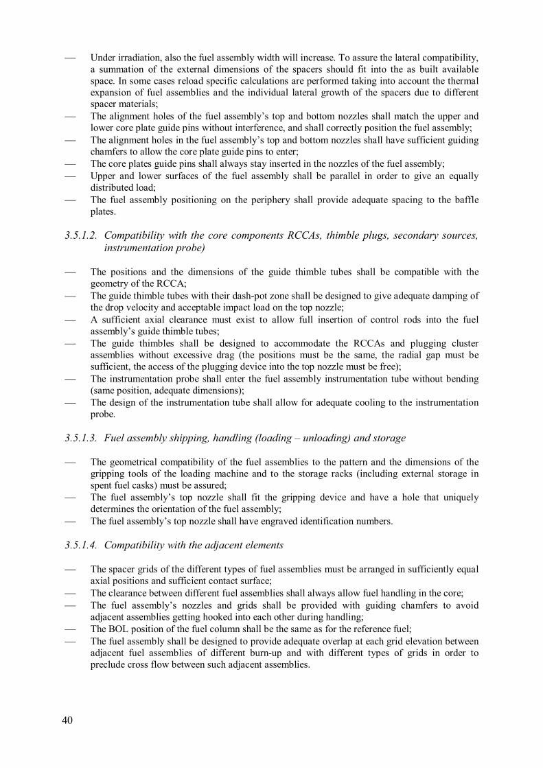
Under irradiation, also the fuel assembly width will increase. To assure the lateral compatibility, a summation of the external dimensions of the spacers should fit into the as built available space. In some cases reload specific calculations are performed taking into account the thermal expansion of fuel assemblies and the individual lateral growth of the spacers due to different spacer materials;
The alignment holes of the fuel assembly’s top and bottom nozzles shall match the upper and lower core plate guide pins without interference, and shall correctly position the fuel assembly;
The alignment holes in the fuel assembly’s top and bottom nozzles shall have sufficient guiding chamfers to allow the core plate guide pins to enter;
The core plates guide pins shall always stay inserted in the nozzles of the fuel assembly; Upper and lower surfaces of the fuel assembly shall be parallel in order to give an equally
distributed load; The fuel assembly positioning on the periphery shall provide adequate spacing to the baffle
plates.
3.5.1.2. Compatibility with the core components RCCAs, thimble plugs, secondary sources,
instrumentation probe)
The positions and the dimensions of the guide thimble tubes shall be compatible with the geometry of the RCCA;
The guide thimble tubes with their dash-pot zone shall be designed to give adequate damping of the drop velocity and acceptable impact load on the top nozzle;
A sufficient axial clearance must exist to allow full insertion of control rods into the fuel assembly’s guide thimble tubes;
The guide thimbles shall be designed to accommodate the RCCAs and plugging cluster assemblies without excessive drag (the positions must be the same, the radial gap must be sufficient, the access of the plugging device into the top nozzle must be free);
The instrumentation probe shall enter the fuel assembly instrumentation tube without bending (same position, adequate dimensions);
The design of the instrumentation tube shall allow for adequate cooling to the instrumentation probe.
3.5.1.3. Fuel assembly shipping, handling (loading – unloading) and storage
The geometrical compatibility of the fuel assemblies to the pattern and the dimensions of the gripping tools of the loading machine and to the storage racks (including external storage in spent fuel casks) must be assured;
The fuel assembly’s top nozzle shall fit the gripping device and have a hole that uniquely determines the orientation of the fuel assembly;
The fuel assembly’s top nozzle shall have engraved identification numbers.
3.5.1.4. Compatibility with the adjacent elements
The spacer grids of the different types of fuel assemblies must be arranged in sufficiently equal axial positions and sufficient contact surface;
The clearance between different fuel assemblies shall always allow fuel handling in the core; The fuel assembly’s nozzles and grids shall be provided with guiding chamfers to avoid
adjacent assemblies getting hooked into each other during handling; The BOL position of the fuel column shall be the same as for the reference fuel; The fuel assembly shall be designed to provide adequate overlap at each grid elevation between
adjacent fuel assemblies of different burn-up and with different types of grids in order to preclude cross flow between such adjacent assemblies.
40

3.5.2. RCCA compatibility All the preceding requirements are related with the geometrical characteristics and the
dimensions of the fuel assembly or bundle and are generally satisfied without problem. However it is worth considering the RCCA compatibility in some detail.
The RCCA spider hub spring retainer impact velocity during a scram shall be less than the
velocity corresponding to a maximum impact force to avoid impact damage to the RCCA spider assembly and top nozzle adapter plate; the order of magnitude of this maximum impact force is between 3500 N –4000 N depending on the plant;
The rodlets of core component assemblies must be able to be fully inserted into the fuel assembly without contact between the rodlet tip and the bottom end of the dashpot or thimble screw tip. A positive gap must exist under worst tolerances. In addition, the compression of the RCCA spring retainer, the compression of the fuel assembly due to the fuel assembly hold-down springs, and the extension of the RCCA absorber rodlets due to deceleration, must be considered. This requirement provides assurance that the RCCAs can function without damaging the fuel assembly;
The RCCA rod drop time shall not be significantly different from the value given in the Technical Specifications so that the assumptions in the accident studies are maintained. The main fuel assembly parameters that affect control rod insertion time are the inner diameter of the guide thimble and the pressure drop in the core.
3.5.3. The thermal-hydraulic compatibility The coolant flow is a major effect coupling adjacent fuel assemblies and needs to be assessed in
detail. The pressure drop of the coolant flow along the length of a fuel assembly is measured individually for each different fuel assembly type using typical in core operating conditions. For cores with different fuel assembly types the distribution of the coolant flow and the flow forces are analysed based on the measured pressure loss coefficients. The flow forces are then used to calculate the hold down forces. In a mixed core situation the coolant flow force applied on a specific fuel assembly depends on the number of fuel assemblies with different pressure drop and their pressure loss coefficient. In case of low margins the hold-down forces have to be analysed individually for each reload.
In addition, pressure drop differences of PWR fuel assemblies can induce cross flow resulting in increased lateral forces on the neighbour fuel assemblies and increased vibration of the fuel rods (Fig. 18). Cross flow in the mid area of the fuel assembly can contribute to fuel assembly bowing whereas cross flow behind the bottom nozzle induces vibration on the ends of the fuel rods with the risk of fretting. In any case, a robust design of the fuel rod support is needed to prevent fretting.
41
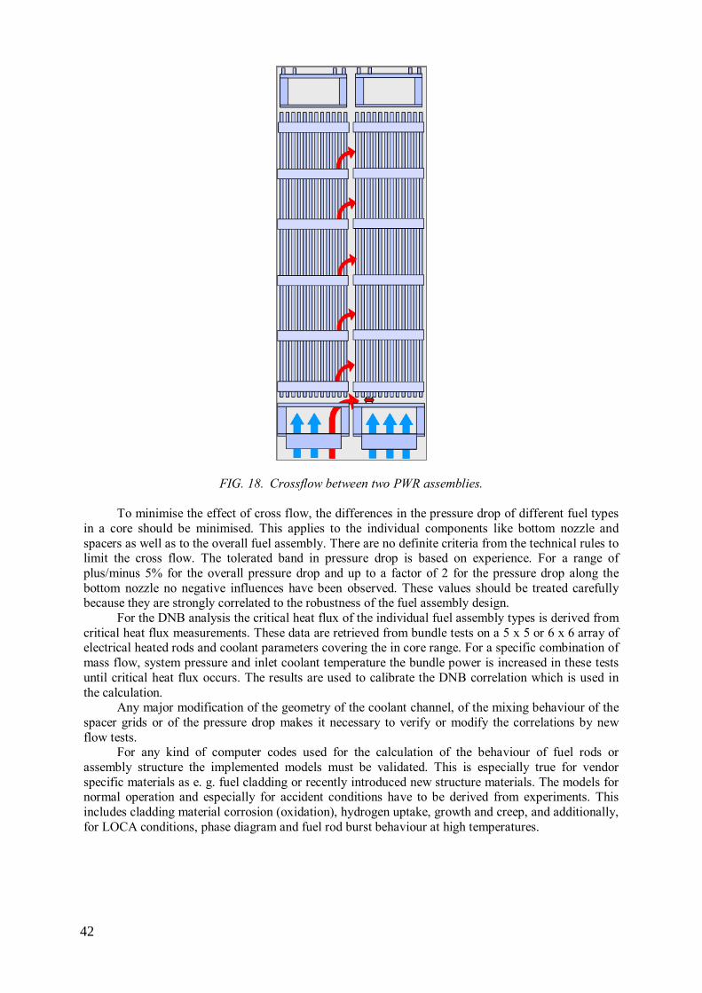
FIG. 18. Crossflow between two PWR assemblies. To minimise the effect of cross flow, the differences in the pressure drop of different fuel types
in a core should be minimised. This applies to the individual components like bottom nozzle and spacers as well as to the overall fuel assembly. There are no definite criteria from the technical rules to limit the cross flow. The tolerated band in pressure drop is based on experience. For a range of plus/minus 5% for the overall pressure drop and up to a factor of 2 for the pressure drop along the bottom nozzle no negative influences have been observed. These values should be treated carefully because they are strongly correlated to the robustness of the fuel assembly design.
For the DNB analysis the critical heat flux of the individual fuel assembly types is derived from critical heat flux measurements. These data are retrieved from bundle tests on a 5 x 5 or 6 x 6 array of electrical heated rods and coolant parameters covering the in core range. For a specific combination of mass flow, system pressure and inlet coolant temperature the bundle power is increased in these tests until critical heat flux occurs. The results are used to calibrate the DNB correlation which is used in the calculation.
Any major modification of the geometry of the coolant channel, of the mixing behaviour of the spacer grids or of the pressure drop makes it necessary to verify or modify the correlations by new flow tests.
For any kind of computer codes used for the calculation of the behaviour of fuel rods or assembly structure the implemented models must be validated. This is especially true for vendor specific materials as e. g. fuel cladding or recently introduced new structure materials. The models for normal operation and especially for accident conditions have to be derived from experiments. This includes cladding material corrosion (oxidation), hydrogen uptake, growth and creep, and additionally, for LOCA conditions, phase diagram and fuel rod burst behaviour at high temperatures.
42

3.5.4. Nuclear compatibility (uranium and gadolinia fuel assemblies) Relevant nuclear parameters such as reactivity, reactivity coefficients, control rod worth and
power density distribution are evaluated for the different fuel assembly types. The nuclear compatibility evaluation is based on single fuel assembly calculations in infinite medium.
The safety of a core is assured by assessing for each cycle the applicable design criteria and associated safety limits on a variety of nuclear parameters, the so called nuclear key safety parameters. These safety limits represent the link between nuclear design and safety analysis.
It is part of the design process for a given cycle to demonstrate that the applicable safety limits are met. In this way it is assured that the conclusions of the safety analysis are valid for the specific cycle in normal operation as well as in fault conditions.
The following calculations are performed as a function of burn-up:
Comparison of the fuel assembly reactivity at different operating conditions (HFP, HZP and CZP);
Comparison of the uranium and plutonium isotopic inventory; Comparison of the xenon and samarium reactivity worths; Comparison of the moderator temperature coefficient and Doppler power coefficient. Also, the
fuel resonance temperatures used as the basis for the Doppler coefficient calculations are compared;
Comparison of the prompt neutron lifetime and effective delayed neutron fractions; Comparison of the control rod reactivity worth; Quantification of the impact of the power distribution due to the presence of a new fuel
assembly next to an old one (rod-wise power distribution, relative assembly power distribution, peak integrated rod power (F∆H)).
3.5.5. LOCA SSE The mechanical design of the fuel assembly structure must satisfy the safety requirements for
the bounding Class IV events, i.e. the LOCA and SSE. Control rod drop and core cooling must remain possible during and after such events. This is translated to criteria for the grid, guide tube and nozzle integrity. Concerning horizontal impact, the maximal impact force must remain smaller than the grid buckling limit.
For calculations of the horizontal impact forces, consideration must be given to the different stiffness and frequency response of the differing assemblies. The manner in which forces are transmitted between assemblies in seismic and seismic LOCA conditions will be affected by the core design and the location of assemblies relative to each type. This is an area where compatibility information needs to be shared between different vendors.
3.6. SOURCE TERM IN LOCA / SEVERE ACCIDENTS The modelling of severe accidents makes bounding assumptions for the extent of fuel failure
and, for mixed cores, the uranium oxide fuel will generally behave identically in terms of the amount of radioactive materials available for release. The source term will not generally vary as a consequence of a mixed core.
For fuels with a significantly different thermal behaviour, generally due to a lower thermal conductivity leading to higher temperatures in a transient, it is necessary to show that they do not cause limiting conditions. For gadolinia doped fuel this is generally assured by the use of a lower enrichment in the doped fuel rods, ensuring that they will be at lower powers and temperatures than surrounding fuel rods, even when the poison effect of the gadolinium has burnt out. There is a potential difference for MOX fuel which is examined in more detail.
43

3.6.1. Impact of MOX fuel Severe accident tests in Japan show no significant differences between MOX and UO2 fuel
behaviour. High burnup MOX fuels irradiated in commercial LWRs were subjected to simulated reactivity insertion accident (RIA) condition pulse-irradiation experiments in the nuclear safety research reactor (NSRR), and computational analysis of the experiments using the RANNS code was performed for better understanding. The present results suggest that the same failure criterion is applicable to UO2 and MOX fuels. Table 2 gives details of MOX test rods irradiated in the NSRR. Rods BZ-1 and BZ-2 failed during the test at similar conditions as standard UO2.
TABLE 2. TEST FUEL RODS AND CONDITIONS IN DW-1, BZ-1, BZ-2, AND BZ-3
Test fuel rod identification
DW-1 BZ-1 BZ-2 BZ-3
Test fuel rod
Nuclear power plant Dodewaard Beznau Beznau Beznau
Rod type 8×8 BWR 14×14 PWR 14×14 PWR 14×14 PWR
Cladding material Zry-2 with
Zr-liner Low-tin Zry-4
Low-tin Zry-4
Low-tin Zry-4
MOX pellets production MIMAS SBR MIMAS MIMAS
Initial Pu enrichment, total (%) 6.4 5.5 5.6 5.6
Initial Pu enrichment, fissile (%) 4.6 4.0 4.1 4.1
Rod average burnup (MW·d/kg) 45 48 59 59
Average oxide thickness (µm) 10 30 20 20 Cladding hydrogen content (wtppm)
50 340 160 160
Test conditions
Coolant temperature (ºC) ~20 ~20 ~20 281
Coolant pressure (MPa) 0.1 0.1 0.1 6.6
Initial fuel enthalpy (J/g)* 0 0 0 70
Maximum fuel enthalpy (J/g)* 497 673 630 594 * 20ºC-based enthalpy, calculated using the RANNS code
Figure 19 shows the test result for rod BZ-3, which did not fail. It shows the evolution of pellet
temperature calculated using the RANNS code. The MOX effect on pellet temperature, which is due to the thermal conductivity and radial power profile, is negligible in the test BZ-3 case.
44

(a) (b)
FIG. 19. Evolution of (a) pellet temperature, (b) PCMI pressure, cladding surface temperature, and
cladding hoop strain in test BZ-3.
Specifically, the following features of MOX fuel behaviour were found:
The results from the test performed with a coolant condition of room temperature and atmospheric pressure were consistent with those obtained in previously-performed tests with high burnup UO2 fuels regarding the rod deformation, FGR, and failure limit;
The computational analysis of the test DW-1 indicated that the pellet temperature evolution during the pulse irradiation was similar to that of UO2 fuels. The PCMI loading on the cladding in rod-axial direction was significantly smaller than in hoop direction and resulted in relatively small PCMI-induced plastic deformation of the cladding. The pellet-clad gap reopening occurred after the end of film boiling, mainly due to the small PCMI-induced cladding deformation. The pressure of the released fission gas had no effect on cladding deformation because of the rather moderate cladding temperature rise during film boiling;
Fission gas release (FGR) from plutonium rich regions of the pellet during the pulse irradiation was estimated to be about 12% based on the scanning electron microscopy (SEM) and electron probe microanalysis (EPMA) data of the MOX pellet sampled from the mother rod of the test rods for BZ-2 and BZ-3. Such additional FGR from plutonium rich regions could account for the large FGR in the test BZ-3. Nevertheless, it cannot be concluded that the large FGR was the result of a MOX effect because relatively large FGRs were observed in the previous high temperature tests performed on high burnup PWR-UO2 tests, compared to room temperature tests. Further investigation is needed to understand the large FGR of 39.4% observed in the test BZ-3.
3.7. USE OF 3-D ANALYSIS FOR REACTIVITY ACCIDENTS The generally accepted approach to analysis of design basis initiating events (IE) implies
performing bounding analysis where key parameters are selected conservatively. For the majority of IEs with reactivity insertion, the analysis is often carried out conservatively using a point-kinetic model or sometimes a 1-D model. Utilization of 3-D analysis has both its advantages and disadvantages. The main advantage is that it allows for the removal of the excessive conservatisms of the 1-D analysis. However, 3-D analysis requires a specific core configuration with specific characteristics which may restrict its applicability for other core configurations.
An example of the use of 3-D methods was in the Ukraine, where at the request of the regulator, a group of initiating events were analysed using 3-D kinetics codes. The analysis was for a mixed core containing Westinghouse assemblies in a host core of TVEL fuel assemblies in a WWER-1000 NPP.
45
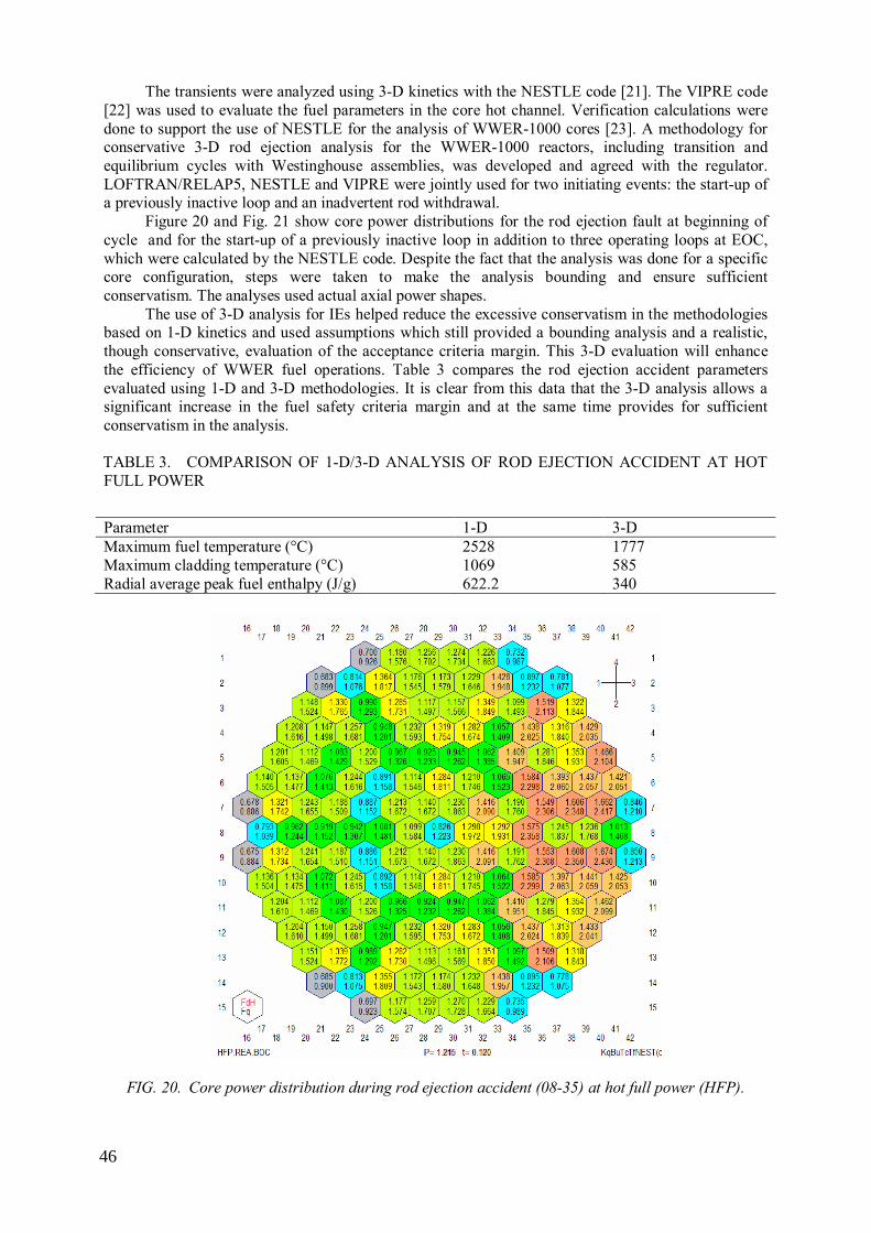
The transients were analyzed using 3-D kinetics with the NESTLE code [21]. The VIPRE code [22] was used to evaluate the fuel parameters in the core hot channel. Verification calculations were done to support the use of NESTLE for the analysis of WWER-1000 cores [23]. A methodology for conservative 3-D rod ejection analysis for the WWER-1000 reactors, including transition and equilibrium cycles with Westinghouse assemblies, was developed and agreed with the regulator. LOFTRAN/RELAP5, NESTLE and VIPRE were jointly used for two initiating events: the start-up of a previously inactive loop and an inadvertent rod withdrawal.
Figure 20 and Fig. 21 show core power distributions for the rod ejection fault at beginning of cycle and for the start-up of a previously inactive loop in addition to three operating loops at EOC, which were calculated by the NESTLE code. Despite the fact that the analysis was done for a specific core configuration, steps were taken to make the analysis bounding and ensure sufficient conservatism. The analyses used actual axial power shapes.
The use of 3-D analysis for IEs helped reduce the excessive conservatism in the methodologies based on 1-D kinetics and used assumptions which still provided a bounding analysis and a realistic, though conservative, evaluation of the acceptance criteria margin. This 3-D evaluation will enhance the efficiency of WWER fuel operations. Table 3 compares the rod ejection accident parameters evaluated using 1-D and 3-D methodologies. It is clear from this data that the 3-D analysis allows a significant increase in the fuel safety criteria margin and at the same time provides for sufficient conservatism in the analysis.
TABLE 3. COMPARISON OF 1-D/3-D ANALYSIS OF ROD EJECTION ACCIDENT AT HOT FULL POWER
Parameter 1-D 3-D Maximum fuel temperature (°С) 2528 1777 Maximum cladding temperature (°С) 1069 585 Radial average peak fuel enthalpy (J/g) 622.2 340
FIG. 20. Core power distribution during rod ejection accident (08-35) at hot full power (HFP).
46

FIG. 21. Core power distribution during startup of previously inactive loop in addition to 3 operating
loops.
3.8. IMPACT ON EXISTING INSTALLATIONS The introduction of mixed cores can have an impact on existing installations, ranging from
receipt and handling of the new assemblies through to modifications of the plant hardware.
3.8.1. MOX A potentially major change in fuel is the introduction of MOX, with the differing neutronics that
it implies. For such mixed cores an increasing broadening and hardening of the neutron spectra is characteristic. Fig. 22 shows the spectral index, which is defined as the relation of the fast neutron flux to the thermal neutron flux averaged over one FA. It combines approximately the properties of the different fuel assemblies as well as the different burn-up and shows the transition from a homogeneous core to a strongly heterogeneous core with MOX assemblies included in a typical German PWR. In cycle 10 the quadrant symmetry, which is usually observed was no longer present.
47

FIG. 22. Development of the radial distribution for the spectral index during the transition
process in a typical German PWR. Such modifications have to comply with the plant hardware properties. In addition, they might
require the adoption of certain features such that the new operational conditions due to the introduction of new fuel can be accommodated. In some plant it will be necessary to increase the number of control assemblies. Other examples for such adaptations are:
Improving the efficiency of borating systems; Modifying the Instrumentation and Control equipment and modifying the Operational
Limitation System; Modifying fresh and spent fuel storage equipment; Modifying transport casks for fresh and/or spent fuel.
3.8.2. NPP upgrading
Typical requirements for a plant introducing new fuel will be to ensure that all their systems are
capable to handle the new fuel, whether from the handling, storage, criticality analysis or interaction with existing plant systems. An example is the introduction of a new fuel vendor for the South Ukraine WWER-1000 reactor which required the use of new methodologies, which included core monitoring using the Westinghouse BEACON system. The system requirements to use this system were not present at South Ukraine NPP and new hardware was installed.
3.8.3. Possible changes/improvement to plant or technical specifications
Mixed core operation is often accompanied by an improved fuel design which is intended to
utilise potential improvements in the operation of the plant. Examples include the increase in thermal output of WWER-1000 NPPs in the Russian Federation which require the implementation of advanced fuel designs. Mixed cores are needed to allow a transition to an equilibrium core with the new fuel design. Another example is the introduction of slightly enriched uranium assemblies into the Argentinian PHWR NPP at Atucha which allows a doubling of the fuel burnup and a corresponding
48

decrease in the required refuelling rate, which is very important for a plant that utilises on-line refuelling.
3.8.4. Fuel related limits leading to operational changes
An example is the change in operating rules implemented at Atucha 1 in Argentina following
the introduction of SEU fuel which allowed a doubling of the discharge irradiation (Section 3.1.1.4).
4. OPERATIONAL EXPERIENCE
4.1. COUNTRY SPECIFIC OPERATIONAL EXPERIENCE
4.1.1. Argentina Atucha-1 is a pressurised heavy water reactor with on-load refuelling and fuel bundles that are
operated vertically and have a fuel stack of 5300 mm in length. The fuel is a very stable product with a consolidated and proven design. The initial design was supplied by SIEMENS-KWU and since 1983 the fuel assemblies have been fabricated in Argentina using standardized and reliable manufacturing technologies. Administration of the design, analysis of non-conformities, qualification of special manufacturing process and fuel failure evaluations are performed in Argentina by CNEA. The fuel assembly consists of 36 fuel rods in an array of three concentric rings and one central fuel rod. A structural tube is placed in one position of the outer ring. An internal tube (gas plenum), a compression spring and isolating pellets complete the internals of the fuel rod.
Two main programs associated with the fuel engineering have been undertaken at Atucha-1. The targets of these programs were to increase the discharge burnup of the fuel and to increase the U content in order to extend the dwell time. In both cases the expected effect was an important reduction in the number of fuel assemblies refuelled per year.
The chosen method to extend the discharge burnup of the fuel was to modify the 235U content, changing from the original natural uranium to slightly enriched uranium (0.85% 235U). This small increment in enrichment provides an almost 100% increase in discharge burnup and a clear reduction of the refuelling frequency.
Several design optimisations were proposed and developed to increase the uranium content. The major ones were a reduction of internal fuel rod components and their replacement with fuel pellets, modifications of the pellet design and the utilization of an additional fuel rod to replace the structural tube.
These modifications were adopted step by step and led to two different mixed cores scenarios:
Cores with fuels with different enrichments but without other significant changes; Cores with fuels with the same enrichment but with different structural designs and also with
different internal fuel rod components designs. The methodology was similar in both cases and the case of the implementation of SEU
assemblies is used as the exemplar.
4.1.1.1. The SEU program The program to increase the enrichment of the fuel was divided into different phases with
different upper limits for the number of SEU fuel assemblies in the core. Licensing documentation and authorizations from the Nuclear Regulatory Authority (ARN) were required for each phase and a Safety Report was prepared for each stage of the program.
49

Phase 1 consisted in the introduction of SEU fuel assembly not exceeding twelve at any time in the core;
Phase 2 was initially defined as the transition period from 12– 60, later extended to 99; Phase 3 from 100 SEU assemblies to full core.
During phase 1, the fresh SEU fuel assembly were introduced in six predetermined channels as
shown in Fig. 23.
FIG. 23. Initial loading positions for SEU fuel assemblies in Atucha 1.
These positions were selected because they had the following convenient features:
A larger margin to the channel power limits which is important to accommodate the higher power increase when introducing fresh SEU fuel;
The channel power is relatively high, which reduces the irradiation time, until the fuel assembly is transferred to another position, leaving the original position free for another SEU fuel;
They are well instrumented with outlet channel temperature measurements and five out of the six have in-core detectors in the vicinity. These allow taking measurements of outlet temperatures and neutron flux to compare them with calculations. The main objectives of phase 1 were:
To verify the performance of the SEU fuel in the core with discharge burnups close to the values expected for the equilibrium full SEU core. In particular, to verify the behaviour in power ramps produced during refuelling operations, reactor power increases, and startups from low power;
To reach discharge burnups of 10 MW·d·kg-1U; To verify predictions of neutronic calculations like reactivity gain, channel power increase and
detector flux increase when introducing SEU fresh fuel assembly; To test operating procedures developed for SEU fuel.
During phases 2 and 3 the average discharge burnup of the SEU fuel was increased to
11 MW·d·kg-1U, and the maximum average burnup of the bundles located in the centre of the core to 10 MW·d·kg-1U.
The main objectives for Phases 2 and 3 were:
To verify the performance of the SEU fuel in the different zones of the reactor at burnups at which they were going to be moved from one channel to another in the SEU core;
50

To verify the performance of the SEU fuel at discharge burnups similar to the foreseen for the full SEU core;
To verify the global behaviour of the core with an increasing fraction of SEU fuel; To prepare the location of SEU fuel assembly in the core for the transition to a full SEU core.
The whole program took almost 6 years. During this time the reactor was operating with
different mixed cores. At the present and since several years ago the reactor is fully loaded with SEU fuel.
4.1.1.2. Post-irradiation SEU fuel performance evaluation
Visual inspection of all the discharged SEU fuel assemblies in a pool-side station was
performed after each stage of the program to complete the evaluation of the SEU fuel performance. Special measurements were performed on some of the irradiated fuel assembly. As an example, Fig. 24 shows the results of fuel rod length measurements at different burnups. These data fits well with model predictions and experimental data from LWR fuel rods.
FIG. 24. Fuel rod length measurements at different burnups.
4.1.2. Armenia
Transition to a new fuel design in the Armenian reactor ANPP Unit 2 was initiated by the fuel
vendor, JSC TVEL, and not the utility. The vendor was stopping production of the first generation fuel and offered a vibration resistant, radially profiled fuel with average enrichment of 3.82% of 235U. As well as the higher enrichment, the new fuel had hafnium plates inserted into the junction of the control rod follower and for the working assemblies, the pitch of the fuel rods and locations of the spacer grids were changed.
The main benefits of the new fuel are:
Fuel enrichment profiling within the fuel assembly cross-section provides a reduction in fuel rod linear power, which leads to improved reliability;
The increased enrichment reduces the quantity of reload fuel, reducing the quantity of fuel sent to storage;
At a higher burnup the fuel dwell life increases and the cost price of electricity output is reduced. The justification and introduction of vibration resistant, profiled fuel was conducted by JSC
TVEL and was based on a planned run of 10 design loadings. The acceptability of fuel load was judged against the initial design standards for reactor core with 349 assemblies, notably:
51

Rod linear power versus burn-up; Rod operational power; Engineering safety factors (standard margin factors); Linear power ramp limits in fuel rods; Coolant temperature and density reactivity coefficients.
The justification required more than twenty new documents and took eighteen months to
complete. Unit 2 reactor original fuel loadings comprised 3.6 % enrichment assemblies and a central
assembly with 1.6% enrichment. The first five new loadings are of mixed type and consist of various quantity of old and new fuel.
The justification included a calculation of the previous reactor operation and the neutron-physical characteristics of the new fuel loadings were specified. Calculations were carried out by the KASKAD code with a modified library of approximation constants to include the new fuel. The selected fuel loadings were designed to ensure that the values of power peaking factors in reactor operation were not exceeded from the start of the modified fuel cycle. Based on the calculated neutron-physical characteristics, reactor core thermal hydraulic calculations were made, demonstrating the absence of DNB in the reactor core. To allow for deviations from the planned cycles, the thermal hydraulic analysis for normal operation and emergency conditions were performed with conservative power flux distributions, where limiting power values are reached, subject to engineering safety factors (standard margin factors). Maximum and minimum values of neutron-physical characteristics were used as initial data for accident analysis.
Analyses of fuel assembly strength in normal operation, transient and accident conditions, including seismic, were performed. Thermal-mechanical calculations were performed to justify fuel rod operability in steady-state and transient operation. Acceptance criteria were:
Strength criteria; Deformation criteria; Thermal-physical criteria; Corrosion criteria; Cladding fretting.
Accident analysis was performed to demonstrate compliance with the acceptance criteria. Initial
events for each acceptance criterion were specified and appropriate calculations were made. The new fuel design loading commenced in 2009 for cycle 21. Starting from the first transition
cycle, deviations from the planned loading patterns occurred due to plant operational conditions. Safety justification for the actual fuel loading was performed by means of a comparison of the calculated neutron-physical characteristics against the design criteria, safety criteria and bounding parameters, and were confirmed in the safety technical justification (STJ) for both the new and old fuel designs.
The main parameters and neutron-physical characteristics which have limit and boundary values and which are used for safety justification of generated fuel loading patterns are:
Fuel rod linear power; Linear power ramp in fuel rod; Reactor core sub-criticality under refuelling conditions and after the scram system is activated; Burn-up; Operation lifetime in reactor core; Fuel assembly 3d peaking factor; Fuel rod radial peaking factor; Fuel assembly power peaking factor; Fuel temperature reactivity coefficient; Coolant temperature reactivity coefficient;
52

Coolant density reactivity coefficient; Boric acid concentration reactivity coefficient; Delayed neutron effective fraction; Prompt neutron lifetime; Working group efficiency; Scram system efficiency with jam; Scram system efficiency with jam and rod ejection; Ejected rod efficiency; Secondary criticality temperature.
For the new fuel, the burnup limit is higher than that for the old, and for Cycle 24, it will be
necessary to justify an increase in burnup for fuel of the old design still in the reactor. For the first three transition cycles, the original burnup limit of 42 MW·d/kg U was not reached, but a new limit of 43.4 MW·d/kgU will need to be approved by the regulator.
There have been no problems connected with fuel damage during the transition cycles.
4.1.3. Belgium GDF-Suez owns and operates 7 nuclear power plants. They are all Westinghouse type PWR, but
with varying characteristics: number of loops (2 and 3), active length (8–14 ft), fuel lattice (14×14, 15×15 and 17×17), and fuel type. There have been up to three different fuel types; enriched natural uranium (ENU), RepU and MOX and fuel with high gadolinium content (up to 8% of the rods with up to 10 w% Gd) which is also considered as a specific fuel type). The plants are operated in base load and they produce roughly 60% of the Belgian electricity needs.
On behalf of Electrabel (the operator), Tractebel (the engineering office) manages the fuel fabrication contracts and is in charge of the in-core fuel management (ICFM) and reload safety evaluations.
ICFM with mixed fuel assemblies is a normal practice in Belgium for the following reasons:
Fuel supply and manufacture are subject to open competition; It is usual to take advantage of design improvements from the current fuel supplier; Burnable absorbers have been introduced and their design is continuously optimized in the
frame of cycle length extension; MOX and REPU have been introduced in some cores some years ago.
4.1.3.1. Mixed core configurations
Doel 2 has experienced the most mixed core. In 1989 ABB-Atom fuel was introduced for the
first time into the reactor whilst the previous supply contracts had covered 3 reloads each. It was at the start of the Belgian mixed core experience, and a major compatibility failure was found when it was too late to be corrected: the guide tubes were not compatible with the thimble plugs. Therefore, a short term operation without thimble plugs in the limited number of ABB assemblies was undertaken. This resulted in a core with five different assembly designs. The following cycles came back to a normal situation but were still loaded with four different designs. Table 4shows the different fuel types used in cycles 15–18 at Doel 2.
TABLE 4. FUEL TYPES USED AT DOEL 2, CYCLES 15–18
D2C15 D2C16 D2C17 D2C18 Std W Std W Std W
Std FRA Std FRA Std FRA Std EXXON Std EXXON
AFA AFA AFA AFA ASEA Atom ASEA Atom ASEA Atom ASEA Atom
53

Both Doel 3 and Tihange 2 utilised MOX fuel from 1995; these mixed cores had two mixing types: neutronic designs:
• MOX with shortened active length; and • UO2 with nominal active length.
several T/H designs: • MOX fuel was an AFA fuel fabricated by Fragema (now AREVA); • UO2 fuel was fabricated by ABB-Atom (now Westinghouse Atom) in Tihange 2; • UO2 fuel was fabricated by Siemens (now AREVA) in Doel 3:
o AKA with standard inconel grids; and o AKA-PA with bi-metallic grids.
Tihange 1 had transition mixed cores as it changed from near-annual to 18-month cycles and
uprated power after steam generator replacement. These cores were rather complex. The power level of the first cycle after the steam generator replacement (cycle 18) was limited due to DNB performances of the old ANF fuel (former Siemens) which were not appropriate for the new operating conditions. The new fuel design has been progressively modified in the following cycles to cope with the new operating conditions. Table 5 summarizes the successive changes in fuel rod design for the resulting mixed cores.
TABLE 5. FUEL ROD DESIGN FEATURES OF MIXED CORES AT TIHANGE 1
Cycle after power uprate 18 19 20 21 Fissile height Nominal -60 mm -30 mm Nominal Pellet density 95% TD 95% TD 96% TD 96% TD Pellet length short short Pre-pressurization 23 bar 23 bar 20 bar 16 bar Plenum spring optimized optimized Rod length +45.2 mm Cladding Standard Standard M5TM(demo) M5TM
4.1.3.2. Incomplete rod insertion
In 1996, the 14 ft Belgian units Tihange 3 and Doel 4 experienced IRI. The phenomenon has
been attributed to an excessive axial load from the hold down springs combined with an inadequate skeleton stiffness causing the assembly to bow and the control rods in such assemblies to fail to insert completely. In 1997, it was decided that the hold-down springs of irradiated fuel assemblies that might be reloaded into the core would be plastified. At Doel 4, from August 1997 to April 1998, 25 of the most damaged irradiated fuel assemblies that were due to be reloaded, were re-caged [24]. For the subsequent reloads, the strength of the hold-down springs was reduced and the guide tubes strengthened.
The evolution of the fuel assembly axial deformations have been closely followed through periodic control rod drop tests during the cycles and measurements during outages. As long as an inter-assembly gap in the core as a result of the axial deformations was believed to be possible, a total penalty of about 10% was been applied on the DNBR evaluation in the frame of the fuel compatibility evaluation [25]. Usually, this can be considered as a design provision, which can be reduced if the rod bow model can justify it.
4.1.3.3. Methodology
A practical methodology applied for the reload safety evaluation has been developed in order to
keep flexibility in-core fuel management in Belgium. The flexibility addresses the cycle length and feed parameter changes, and the ability to move from one fuel vendor to another or from one design to another from the same fuel vendor without reviewing the full safety analysis.
54

This methodology is based on a reference core and a reference fuel which are considered in the safety analysis with adequate design provisions to allow this future flexibility. The choice of these design provisions results from a trade-off between the operating flexibility target and the licensing need to keep adequate licensing margins.
For the introduction of a new fuel type, compatibility with the FSAR is verified through a limited number of interface parameters and a limited amount of design and safety evaluations [26], [27]. This verification is performed for a new equilibrium core including the new fuel design.
The same principles are extended to verify the compatibility of the new fuel with co-resident fuels in any transition core from the initial core to the new equilibrium core which include the new fuel.
This approach allows the required flexibility for in-core fuel management with mixed cores while ensuring the safety of the reloads.
4.1.4. Hungary
The PAKS NPP in Hungary has four WWER-440 units which have been operated on annual
cycles. Fig. 25 shows the main changes in fuel types used with the dates of introduction
Original (1982) 126 fuel pins (uniform) 1.6%, or 2.4%, or 3.6%
central tube 12.2 mm lattice pitch
Profiled (2000, 2005)
non-uniform 4.0%, 3.6%, 3.3%
3.82% average central tube
12.2 or 12.3 mm lattice pitch
Gd-2n (2010) UO2+ Gd2O3
4.4%, 4.0%, 3.6% 4.2% average central tube
12.3 mm lattice pitch
FIG. 25. Fuel types used in Paks NPP, WWER-440.
The improvements and changes that have been made include:
The exchange of spacer grids from stainless steel to zirconium alloy providing less absorption in structural materials;
A reduction of the shroud wall thickness (2–1.5 mm) which changed the by-pass flow rate because of different key-sizes of the assemblies;
Recovery of the key-size and increasing the lattice pitch of the fuel pins in the assemblies to reduce the excess power in the peripheral fuel pins because of the thinner wall (excess moderator);
Hafnium shielding of the follower heads to reduce local power peaking near the head of the follower assembly (excess moderator).
55

4.1.5. India Indian PHWRs use 19-element bundles using natural uranium as the fuel material. In order to
attain the design rated power from the beginning of operation of a reactor, mixed core loading patterns are adopted. Different mixed core loading patterns have been used in Indian PHWRs and are explained below
4.1.5.1. Use of depleted uranium
At the start of the Indian nuclear power programme, for the initial core of a new reactor 656
depleted uranium fuel bundles were loaded in the inner region of the core to achieve flux flattening and commence reactor operation. Later, detailed studies indicated that it was possible to operate the reactor at rated power from the initial loading with a reduced number of depleted uranium fuel bundles loaded in the inner region of the core.
4.1.5.2. Use of 22-element natural uranium 22–element natural uranium fuel bundles were loaded into one of the PHWRs to gain
experience of using sub-divided fuel bundles, i.e. fuel bundles with thinner elements for high power reactors. These bundles were considered to give better heat ratings due to thinner elements and increased heat transfer surface area. However, due to an increase in the ratio of surface area to volume of the fuel, there is a slight reduction in the core excess reactivity. Safety analysis was performed with 22–element fuel bundles and it was found to be satisfactory. 22–element bundles were loaded in the first charge of one of the NPPs along with depleted uranium (DU) fuel bundles (for flux flattening) and remaining natural uranium fuel bundles of regular 19-element design.
4.1.5.3. Use of thorium
The number of depleted bundles required is greater for flux flattening in the fresh core.
However, if thorium fuel bundles are used for flux flattening, few are needed and they are spread thinly throughout the core. This is due to the fact that thorium is a strong absorber of neutrons when loaded fresh and hence causes a local flux depression, whereas depleted uranium fissions at only a slightly reduced rate and does not create a significant local flux depression. With burnup, thorium is also converted to 233U, which then starts to undergo a fission reaction and the flux depression gradually reduces.
4.1.5.4. Combination of deeply depleted uranium and depleted uranium
For the past few years, due to a mismatch between the fuel supply and its requirement, all the
units have been operating at a reduced power level, which provides flexibility for the operator to shift from a flat flux to a centrally peaked flux for better fuel economy. Taking advantage of peaked flux operation, a limited use of depleted fuel bundles has been used in the reactor for regular refuelling. Also, in order to conserve natural uranium resources, fresh cores have been designed with a large scale use of depleted fuel bundles, more than that required for flux flattening.
Further, a few deeply depleted fuel bundles have been used in the regions of low flux levels, i.e. in the peripheral regions of the reactor core to avoid using natural fuel bundles in those locations.
Some NPPs in India are under IAEA safeguards and imported uranium fuel bundles can be used. During fresh fuel loading in such reactor cores, deeply depleted fuel bundles have been used for flux flattening along with all other natural uranium fuel bundles. When deeply depleted uranium is loaded in the regions of higher flux, the photo-neutrons emitted by 232U present in deeply depleted uranium (DDU) fuel play an important role in the neutron monitoring. Hence, while estimating the expected neutron count-rates during fuel loading and approach to criticality, due credit has to be taken for these photo-neutrons along with the spontaneous fission source of 238U.
56

4.1.5.5. Use of SEU Presently SEU bundles with enrichment of 0.9%w/w are being irradiated in one reactor for a
trial irradiation. These bundles are loaded at discrete locations in the core along with other natural uranium fuel bundles. These SEU bundles have been shifted from low flux regions to high flux regions to test their capability to withstand design bundle powers and power ramps and attempts are being made to irradiate these bundles to design burn-up to assess their performance. Detailed safety review was carried out before approval of loading these bundles in the reactor core.
India has demonstrated long and successful operation of PHWRs with mixed core loading. The core loadings included DU, DDU, Thorium, 22-element NU and SEU fuel bundles along with normal 19-element NU bundles. Safety analysis has been carried out for each mixed core loading and demonstrated that the safety parameters are within limits. The operating experience has been satisfactory and the intent of using various combinations has been fulfilled.
4.1.6. Russian Federation
4.1.6.1. Fuel designs In the course of fuel improvement for the WWER-1000 reactor, five types of fuel assemblies
have been designed by Gidropress, Fig. 26. FA for WWER-1000 (EDO “GIDROPRESS” design)
ТВС-М
Пучок
(жесткий каркас,
ЦДР увеличенной
высоты и ячейка с
толщиной стенки 0,3 мм,
каналы из сплава Э635)
Пучок
(циркониевыйжесткий каркас,
ЦДР увеличенной
высоты и ячейка с
толщиной стенки 0,3 мм,каналы из сплава Э635,
оптимизировано
количество ЦДР
увеличена на 150 ммвысота топливного
столба)
Решетка нижняя
Хвостовик
Решетка нижняя
(цанговое закрепление
твэлов/твэгов)
ТВС-2МУТВС
Головка,
повышена жесткость
обечайки,
улучшенныйтермоконтроль)
ТВС-2
Головка50
мм
100
мм
50
мм
ТВС
ТВС-2 и ее модификации
TVS TVS-M UTVS TVS-2 TVS-
TVS-2 and its modifications
FIG. 26. Fuel assembly for WWER-1000 (EDO “GIDROPRESS” design)
The first type of fuel assembly (TVS) for WWER-1000 design had a skeleton based on spacer
grids and guide thimbles made of stainless steel. The second type (TVS-M) is a variety of the original TVS. Excessive hold-down force on the fuel assembly in operation had been experienced and a new hold-down unit was developed. This unit allowed a longer design stroke of springs.
The third design, (UTVS) was characterized by a transition to a skeleton manufactured from zirconium alloy spacer grids and guide thimbles. The fourth design (TVS-2) has a rigid skeleton to ensure acceptable distortion during operation in the core.
The fifth design (TVS-2M) has an elongated fuel stack and has other variations used in modern NPP designs (AES-2006, WWER-TOI), but all are based on TVS-2M technical solutions.
57
4.1.6.2. Examples of mixed core operation
The first example is a core with a mixture of TVS (TVS-M) and UTVS, i.e. fuel assemblies
with skeletons of different materials. The geometries of fuel bundle and the skeleton were the same, so there were no concerns with hydraulic compatibility. The only task was to ensure an acceptable hold-down force in reactor for both types. The designer had to find the balance between preventing fuel assembly lift-off and excessive hold-down forces, taking into account different thermal expansion coefficients. Reduction of the quantity of stainless steel in the core led to an increase in fuel dwell from two to three years.
Mixed core operation revealed that fuel assembly of different designs had no effect on fuel reliability. A higher fuel failure rate at the beginning of operation was experienced, but was associated with initial operational and manufacturing problems. The common problem with both designs was a low resistance to bowing, which required a further improvement in the design.
A second example is the implementation of fuel assemblies with an integrated burnable absorber (Gd2O3) instead of the use of discrete burnable absorber rods containing CrВ2. The mechanical design of assembly was unchanged, only the core physics properties were changed. As a result of this transition fuel reliability did not change. Positive results were achieved in the areas of fuel utilization efficiency and a decrease in the volume of radiation wastes as well as other issues.
Problems of compatibility between fuel assemblies of different designs were more significant with the introduction of TVS-2 with a rigid skeleton. In spite of the better resistance to distortion of TVS-2 it was necessary to demonstrate mechanical and thermal-hydraulic reliability of the mixed core. The mechanical reliability of the TVS-2 implementation was undertaken in three stages:
Loading of TVS-2 with 15 spacer grids with the span corresponding to that of the UTVS design
(255 mm); Decreasing number of spacer grids, located with different spans (510 and 255 mm); Full implementation of TVS-2 with the single span of 340 mm.
The first stage required thorough justification due to a large difference in pressure loss
coefficients (12.5 and 16.4 respectively). The unique characteristics of the units and specific core physics were taken into account. In the second and third transition loadings, the hydro-dynamic situation became smoother and the justification of the equilibrium fuel cycle used generalized conservative data on coolant flowrate and core physics.
To account of the increased cross-flow due to differing axial locations of the spacer grids, a 3% penalty on DNBR was introduced. Successful operation of this transition, from both thermal-hydraulic and mechanical points of view, was seen at five NPPs. As a result of the introduction of fuel assemblies with a rigid skeleton, the periodic RCCA drop tests at the plant were no longer required.
The most recent example mixed core operation has been as a result of the implementation of TVS-2M with an elongated fuel stack. For this case, blanket zones were introduced into fuel assembly design in the bottom and upper parts of the fuel rods, Fig. 4. Having reached an equilibrium state from the point of fuel assembly design, the blanket zones were replaced by enriched uranium in order to provide the maximum fuel cycle length at an uprated thermal power of 104% nominal (Table 6).
58

TABLE 6. TRANSITION TO 18 MONTHS FUEL CYCLE ACCOMPANIED BY REACTOR THERMAL POWER UPRATE TO 104% NOMINAL
Parameter Fuel cycle: 3×1.5 year Fuel assembly type TVS-2 TVS-2M Number of fuel assemblies in reload batch, (pcs). 70 67 Average enrichment 235U, (wt%) 4.54 4.73 Fuel cycle length, (EFPD) 464 498.7 Burnup, (MW⋅day / kg U):
- Batch average - Fuel assembly maximum
46.1 52.1
49.9 56.1
The improvements in design provide for implementation in the new NPP designs AES-2006 and
WWER-TOI. The TVS-2(2M) performance is as follows:
RCCA drop time – less than 2.5 s.; RCCA drag force – less than 60 N; Core loading-unloading forces – within design limits (±750 N); Fuel handling rate in the core – 1.2 m/min (maximum – 4.0 m/min); Reached load factor – 90% (with reliable equipment operation); Coolant activity < 1.0·10-5 Ci/kg; Integrated indicator of absence of TVS-2 (2M) distortion – average fuel assembly growth ~ 1.5
mm per cycle.
4.1.7. Sweden Several different types of mixed core situations have occurred in Ringhals 2, 3 and 4 over the
last two decades. These are described and comments on the operational experience related to mixed core effects are made.
4.1.7.1. Introduction of fuel with mid-span mixing grids Fuel with intermediate flow mixers (IFM) was introduced at all Ringhals PWR Units in the 90s,
to improve fuel thermal performance in the plants. In Ringhals 2, which is a 15 × 15 plant, Westinghouse’s Performance+ was introduced as lead fuel in 1993 and as reload in 1995. The introduction was complemented by a study of increased peaking factors, taking credit for the superior CHF performance of fuel with IFM’s as well as improvements in LOCA methods. This allowed the increase of F∆H from 1.65–1.75 and FQ from 2.34– 2.50. In Ringhals 3 and 4, which are 17 × 17 plants, Framatome’s AFA-2G was replaced by AFA-3G with IFMs (mid-span mixing grids) in 1999 (lead assemblies in Ringhals 4 in 1998). In these cases, no complementary safety analyses were performed.
The introduction of fuel with IFMs increased the fuel pressure loss coefficients by at least 5%, causing a significant flow starvation of these assemblies. However, the shortened grid span and improved mixing in the upper part of the assembly was shown to offset this effect and still provide additional DNB margins, even in the extreme case of one fuel assembly with IFMs in a core fuelled otherwise without IFMs.
Another important aspect to check for the introduction of fuel with IFMs was the cross flow velocities upstream the IFMs. For the transition from AFA-2G to AFA-3G in Ringhals 3 and 4, Framatome could confirm in flow tests that these values were within the envelope considered for fuel rod vibration analyses. However, the corresponding check was not performed for Ringhals 2, since resident and reload fuel came from different vendors.
In Ringhals 2 the increase in pressure loss coefficient was more than 15%. This resulted in significant flow redistribution towards the resident KWU fuel assemblies without IFMs. In effect lift forces on Performance+ were lower than nominal. The hold-down package was already over-
59

dimensioned, but the net force was now even higher. Significant cross flow also gave a transversal force on the assemblies. Together these factors may have assisted the development of fuel assembly bow in Ringhals 2 in the late 90s. However, the main reasons for the bow development are to be found in the mechanical design of Performance+ without reinforced dashpot and optimized hold-down springs. In this context it should also be noted that from mechanical design perspective IFMs are advantageous for the resistance to bow. Increased quadrant power tilt was noted and in the following outage in 2000, high bow amplitudes were confirmed. Comprehensive and detailed analyses were performed by Westinghouse to determine the effect on safety margins.
With the introduction of Areva’s HTP fuel design in Ringhals 3 and 4 in 2003 (lead assemblies in Ringhals 3 in 2000), the expected total pressure loss coefficient was somewhat lower than that of the dominant fuel design in the core, AFA 3G. However, this figure was later significantly increased as new pressure loss measurements on the HTP spacer, inexplicably, revealed much higher values than the original tests. Thus, the flow redistribution evaluation and argumentation performed for the HTP fuel licensing was based on incorrect data and had to be revisited. Although HTP was now seen to be flow starved in the mixed core, net DNBR margins compared to the SAR could be shown, since the improved thermal performance for fuel with IFM’s had not yet been credited in the safety analyses for Ringhals 3 and 4. The impact on lift forces could also be shown to be acceptable.
Operating experience at Ringhals 3 and 4 shows no negative mixed core effects from the introduction of fuel designs with IFMs. However, the mixed core situation after the introduction of Westinghouse fuel with IFMs - but without reinforced dashpot and optimized hold-down springs - may have assisted the development of collective fuel assembly bow in Ringhals 2.
4.1.7.2. Introduction of fuel with low flow resistance
Optimization of the debris mitigation function and pressure loss in the bottom nozzle of the fuel
has on some occasions caused significant changes in pressure loss over the lower core plate and bottom nozzle. For example, going from an anti-debris nozzle with flow holes in AFA 2G to an anti-debris nozzle with mesh structure in AFA 3G imposed a local pressure loss decrease of more than 50%. This could potentially cause high cross flow velocities acting on the fuel at the core entrance. The fuel vendor thus had to confirm in additional flow tests that these values were within the envelope considered for fuel rod vibration analyses.
The replacement of Performance+ with AFA 3G in Ringhals 2 in 2003 (lead assemblies in 2000) resulted in lowered pressure loss coefficients over the whole core height, amounting in total to a 10% decrease. It is possible that the cross flows present in this mixed core situation provided transverse forces that were detrimental for the bow development. This is, however, not verifiable.
According to the information provided by the vendors, the replacement of HTP with Westinghouse RFA-2 in Ringhals 3 and 4 in 2011 and 2012 (pre-delivery to Ringhals 3 in 2010) would give a total pressure loss decrease in excess of 10%. However, Vattenfall’s review finally concluded that differences in assumptions regarding core components in the top nozzle accounted for half of the difference between Areva and Westinghouse fuel. The final calculations corrected for this issue.
Operating experience at Ringhals 2, 3 and 4 shows no evidence of negative mixed core effects from the introduction of fuel designs with significantly lower flow resistance than the resident fuel.
4.1.7.3. Introduction of shielding assemblies
In Ringhals 3 and Ringhals 4, shielding assemblies (SA) of HTP design were introduced in
2009, in 12 peripheral positions of the core in order to prolong the vessel life-time by reducing the belt-line weld fluence. In the SA, the guide thimbles and three rows of fuel rods are replaced by stainless steel bars. Thus, both neutron absorption and the fuel assembly stiffness are significantly increased. Due to the use of sleeves to allow the connection of the grids to the stainless steel bars, the pressure loss coefficients are also increased.
The reduced number of heated rods together with an unchanged thermal power level leads to an increase in average surface heat flux in the rest of the core. Therefore, peaking factor limits have to be reduced to the same degree, to ensure that the maximum heat flux in the core is not increased.
60

The introduction of SA results in a permanent mixed core situation at Ringhals 3 and 4, since the shielding assemblies will stay in the core for around eight years and then be replaced by new shielding assemblies, possibly of optimized design.
Due to the higher pressure loss coefficients, flow will be diverted from the peripheral SA to inner assemblies. From a thermal-hydraulic point of view, the mixed core effects on fully fuelled assemblies can thus conservatively be neglected. However, the high stiffness of the SA has a non-negligible influence on the propagation of mechanical loads in the core during a combined earthquake and LOCA. Recent analysis of mechanical margins under combined LOCA and seismic (SSE) loads for RFA-2 licensing for Ringhals 3 shows that the impact of SA on adjacent assemblies is rather small and that calculated grid crushes are limited to the core periphery, as was the case without SA. This, together with confirmation that all affected assemblies are low power assemblies and the RCCA function is not prevented, allow for the conclusion that coolable core geometry is preserved.
Operating experience at Ringhals 3 and 4 shows no negative mixed core effects from the introduction of shielding assemblies.
4.1.7.4. The special case of introduction of fuel from one vendor in parallel with revision of
the SAR by another vendor One consequence of purchasing fuel and safety analyses in free competition between the
vendors is that even if it is always the most economical, it may not always be the most practical alternative that is chosen, even if it is feasible. Additional licensing and analysis costs for choosing a less practical alternative are generally minor in comparison to the total fuel costs or safety analyses costs.
Examples of such situations are the introduction of fuel from one vendor in parallel with revision of the SAR by another vendor. This has occurred in both Ringhals 3 and 4 in recent years. Ringhals 3 uprating safety analyses were performed by Westinghouse and were finalized in parallel with the licensing of Areva’s HTP design for a new 4-year contract period starting 2007. Ringhals 4 uprating and steam generator replacement (SGR) safety analyses were performed by Areva and were finalized in parallel with the licensing of Westinghouse’s RFA-2 design for a first 4-year contract period starting 2012.
The mismatch between the reference fuel type assumed in safety analyses and the fuel to be loaded, requires an increased scope of fuel vendor analyses to show compatibility. This work is facilitated by the provision of an IDFL from the safety analysis vendor. Vattenfall’s experience is that active involvement from the vendor receiving the IDFL is necessary at an early stage in order to avoid conflicts between the data format of the boundary conditions provided by one vendor and that needed for the other vendor’s codes and methods.
Currently, Vattenfall and Westinghouse have had some difficulties to show compatibility between RFA-2 and the realistic LBLOCA analyses from Ringhals 4 Uprating/SGR project. Partly because the IDFL LOCA data proved to be insufficient for Westinghouse’s needs and partly because the PCT margin from the reference analysis is so small. This calls for improvements in the IDFL and possibly use of a generic PCT margin for future LOCA SAR updates in Ringhals.
4.1.7.5. Introduction of lead fuel assemblies
Lead fuel assembly (LFA) projects are systematically initiated by Vattenfall in order to evaluate
improved fuel designs and to ensure that several competing designs will be offered by the vendors in the next fuel bid. In general, Vattenfall’s requirements for an LFA licensing project are the same as for reload fuel licensing projects. Some reduction in the scope of analyses may be acceptable under special circumstances, but to facilitate future reload scale operation full-scope analyses are preferred. This also means that the ensuing mixed core situations should be fully analysed by the vendor and Vattenfall.
Currently, there are on-going LFA projects for all three PWRs in Ringhals. For Ringhals 2 Areva’s Improved AGORA 5A will be introduced as LFAs in 2012. This will ensure that there will be competition for Westinghouse’s current reload fuel 15×15 upgrade in the next fuel bid in 2016. For Ringhals 3, Areva’s new GAIA design will be introduced as LFAs in 2012. For Ringhals 4
61

Westinghouse’s new NGF design will be introduced as LFAs in 2013. These fuel types are expected to further improve safety margins and dimensional stability and may be offered as alternatives to previously used designs in forthcoming fuel bids.
Operating experience at Ringhals 2, 3 and 4 shows no evidence of negative mixed core effects from the introduction of small quantities of LFAs.
4.1.8. Switzerland Switzerland has three PWR and two BWR NPPs. The PWRs have had a consistent fuel
assembly design, with a single vendor. Fuel variants have included RepU and MOX and changes to the assembly structure have included debris filters and spacers. There have also been test fuel rods to test cladding and doped fuel.
The BWR NPPs have had two vendors, Westinghouse, AREVA. There have been many different varieties of fuel design with Svea96 and Atrium10 (Fig. 27) in use. Gadolinium doped fuel has been used and part length rods introduced. Fig. 28 shows the evolution of fuel type at Liebstadt BWR.
Svea96-design Atrium10-design
FIG. 27. 10×10 BWR fuel types used in Switzerland.
FIG. 28. Evolution of core composition in the Swiss BWR Leibstadt.
62

4.1.9. Ukraine In 2010, 42 Westinghouse fuel assemblies were loaded into the core of South Ukraine Nuclear
Power Plant (SUNPP) Unit 3 after four successful cycles with six Westinghouse lead test assemblies. The scope of safety substantiating documents required for the regulatory approval of this mixed core was extended considerably, particularly with development and implementation of new methodologies and 3-D kinetic codes. Additional verification for all employed codes was performed.
Despite the inherent hydraulic non-uniformity of a mixed core, it was possible to demonstrate that all design and operating restrictions for the three different types of fuel (TVS-M, TVSA and WFA) loaded in the core, were conservatively met.
4.1.9.1. Operational results of the 42 WFA
The 42 WFAs loaded into the SUNPP Unit 3 core were successfully operated during the entire
cycle. The fuel cycle length was 270.3 effective full power days (EFPD). Due to the restrictions imposed by grid requirements the unit was operated at low power for part of the cycle. The core loading pattern is shown in Fig. 29. The WFAs are designated as 362VG and 334WG in the figure, other designations correspond to regular resident fuel designations (TVS-M and TVSA).
FIG. 29. Core loading pattern with 42 WFAs.
During operation, core monitoring was done by the resident plant systems. The comparison of
measurements and predictions for the critical boron concentration, power distributions throughout the cycle, control bank worth and reactivity coefficients at HZP showed that the differences were within the calculation methodology uncertainties.
Core monitoring was done by the in-core monitoring system based on the self-powered detector (SPD) measurements using BEACON hardware and software set. At the insistence of Ukrainian regulator, the BEACON system was additionally tested and demonstrated to have reliable operation
63

even with fewer than the four reactor coolant loops in operation. The maximum peaking factors calculated by BEACON during the cycle are provided in Fig. 30.
Peaking Factors
0
0.2
0.4
0.6
0.8
1
1.2
1.4
1.6
1.8
2
0 50 100 150 200 250 300
EFPD
Kq
Kr
Kv
K0
RelPower
FIG. 30. Maximum cycle peaking factors.
The coolant activity during the cycle was within the operating limits and had sufficient margin
in terms of total specific 131I – 135I activities. The fuel rod leakage analyses conducted during reactor operation identified a minor gas leakage
defect. During the 2011 outage, the fuel rod leakage test based on statistical analysis of sample activities resulted in a decision to remove one three-times-burnt non-WFA from the core.
In accordance with the pilot-commercial operation program for the 2011 outage, the WFAs were visually examined and inspected. The scope and the results of the inspections are summarized below:
TABLE 7. INSPECTION RESULTS FOR THE WFA LEAD TEST ASSEMBLIES
Inspection Type Results WFA drag force Drag force did not exceed 50 kgf. One fuel assembly had the
maximum drag force of ∼80 kgf Drag force during WFA loading into the core
Drag force did not exceed 75 kgf. For a number of fuel assemblies in the central zone the drag force reached 150 kgf
WFA top nozzle axial difference Did not exceed 5 mm after the first operating cycle RCCA drop time Maximum control rod drop time throughout cycle – 2.1 sec RCCA drag force during loading into/withdrawal from the WFA
Within specified limits, not exceeding 4 kgf
Leakage test No leaking fuel rods were identified WFA visual inspection No damage was identified preventing further WFA operation
Safety substantiations for the WWER-1000 core with WFA reload batches have been prepared.
The transition cycles and the equilibrium cycle with an annual feed of 42 WFAs have also been developed. The nuclear parameters of the equilibrium cycle with WFAs are similar to those of the annual fuel cycle with TVS-A currently being operated at Ukraine's NPPs with WWER-1000.
Mixed cores were designed using Westinghouse codes and methodologies. These allowed the performance of a thermal-hydraulic and nuclear design of the core that ensures that safety criteria are met. The codes and methodologies employed have been continuously verified based on the operational data.
64

One concern for the mixed core arises from the phasing out of the co-resident TVS-A fuel type as the proportion of WFA increases. The TVS-A design is designed to have sufficient stiffness to withstand bowing, but as the hydraulic resistance differs from the WFA, the mechanical load on them will increase. It will be necessary to demonstrate that this is not the case.
Based on the safety substantiation analysis that has been performed and the positive operational experience, it can be stated that safety limits and conditions for the various types of fuel jointly operating in the mixed core are currently being met.
4.1.10. United Kingdom
The transition from the original fuel vendor (OFV), to the NFV, Siemens, was carried out for
cycle 5 at Sizewell-B NPP. Cycle 5 went critical in October 2000. It used 80 NFV assemblies. Following the review of the performance of the fuel using a systematic approach to the
licensing, it was decide to implement several design changes to the new fuel vendor’s fuel design before manufacture. These changes (in fuel rod length and assembly length) were mainly to reduce fuel rod internal pressure when irradiated but also moved the fuel geometry closer to the existing fuel design. The top nozzle was also changed from a cast to a welded design to increase strength and reduce variation in pressure drop.
The experience of the mixed core in cycle 5 was:
Fuelling and building of the core was entirely satisfactory; Core reactivity was satisfactorily predicted both at start-up and through cycle; Core physics testing was generally satisfactorily although there was a small asymmetrical cross-
core tilt in power distribution. This tilt resulted in a maximum power discrepancy of near to the 10% limit at first the low-power flux map (8% power), although the error reduced to approximately 5% when at full power;
Operation of the cycle was satisfactory, although the cycle was interrupted by a leak from a valve in the reactor coolant system which required the plant to go to cold shutdown conditions for repair;
Towards the end of cycle, coolant activity indicated fuel failures. In-mast sipping and ultrasonic testing of the core revealed four assemblies containing failed rod(s). All these assemblies were of the old design and first loaded in cycles 3 and 4; there were no failures in the new fuel design. Cycle 6 went critical in May 2002. It used 160 NFV assemblies:
Fuelling and building of the core was entirely satisfactory; Core physics testing again showed a similar pattern of cross-core deviation to the previous
cycle; The operation of the cycle was without incident; A further fuel failure was found in initial charge fuel re-used in cycle 6. Again, no failures were
found in the new fuel design. While both cycles 5 and 6 had significant number of fuel failures, these are not believed to
directly result from the operation with a mixed core. Significant numbers of fuel failures had been seen in the previous cycles 3 and 4; e.g. in cycle 4, twelve individual fuel rod failures were located, distributed amongst nine fuel assemblies, with these failure attributed to a mixture of grid/rod fretting and debris. The failures seen in cycles 5 and 6 were attributed to a continuation of these effects.
Only one fuel assembly of the new design has subsequently failed during six complete reload cycles. This failure involved three non-contiguous internal rods and is pending examination.
In general the transition project was a success and yielded both financial and operational benefits to the company as well as a significant increase in in-house capabilities and understanding.
One notable issue which caused confusion was the identified list of fuel safety-case requirements (FSCR). This list was intended to help ensure completeness and avoid neglecting any safety parameters or interface data, and was successful at providing a checklist to aid verification.
65

Confusion was caused by interpreting the FSCRs as safety parameters themselves (a fact perhaps not helped by the name chosen). While some of the FSCRs were indeed copies of the key safety parameters, others merely represented interfaces and could be redefined or dropped due to performing analysis is different ways.
Some issues were not identified in sufficient depth at the beginning of the programme and additional effort was needed to resolve on the timescale of the safety submissions; one example was the link between the nuclear design codes and the plant flux map measurement system (where the existing Westinghouse analysis codes were retained).
Continuing reliance on the OFV codes for the fault analysis aspects has led to less analysis flexibility in this area than the other technical areas; while moving the fault analysis codes to the NFV codes (or other UK-based codes) would have significantly increased the scope of the case, it would have also yielded benefits in this area.
Additional changes have subsequently been performed on the fuel assembly design to update materials and construction to take advantage of mature technologies and ensure that the Sizewell-B design does not become obsolete. These have included a further change in cladding material which will in the future be used to support an increased burnup limit.
4.1.11. United States of America
Operating experience of PWR and BWR has shown that cores loaded with mixed fuel are
known to have reduced stability margins [28] [29]. A large mismatch in flow and pressure drop between neighboring fuel assemblies in a mixed core that can be further exaggerated by the core reload operating scheme can contribute to thermal-hydraulic instability of the core. For BWRs, stability is of concern at low flows, especially at natural circulation where T-H conditions are significantly different from full flow and power. Simulations have shown that even if two fuel elements are perfectly matched at full flow, the axial void fraction distribution changes significantly when the flow is reduced to natural circulation conditions and the two fuel elements are not fully thermal-hydraulically compatible at reduced flows [28]. This means that fuel elements that are perfectly matched thermo-hydraulically at full flow conditions can have significantly different flows at off-rated operating conditions. Therefore, mixed cores must be analyzed and its safety impact must be evaluated for stability.
4.2. OPERATION WITH LEAD TEST ASSEMBLIES
Many of the country specific reports above refer to the use of a lead test assembly programme before using a new fuel design and this can be mandated by the local regulator. Generally this programme will include a small number of fuel assemblies (typically 1–4) placed in the core for one or more cycles before implementation of a new fuel design. The licensing of such a programme needs to be carried out in a similar manner as discussed in this report, as it comprises a mixed core project in itself. However with the small number of assemblies involved, it is generally easier to make specific safety provision for them as they will also be subject to detailed examinations to ensure proper operation.
Smaller programmes can also be undertaken with a lead test rod or rods inserted into an assembly of the standard design for the plant. Such programmes might be used to investigate the compatibility of a new clad material or other fuel rod specific change. Also, fuel assemblies can be retained in the core for extended periods to investigate the potential to extend the burnup of fuel and this also needs appropriate safety justification.
4.3. FUEL MANAGEMENT WITH MIXED CORES There have been no reports of any fuel management issues attributable to mixed cores.
66

4.4. PROBLEMS ENCOUNTERED WITH MIXED CORES Some problems with mixed cores were noted in the country specific reports, one was with the
methodology for calculating the local power of MOX assemblies and another is the assembly bowing that was seen in Belgium that might have been associated with mixed cores. However, mixed cores are more usually associated with attempts to improve an existing problem or instituted to obtain a benefit in economics or burnup.
The issue of assembly bow and twisting leading to incomplete insertion of control rods was first reported in the United States in 1995 [30] with high burnup fuel, and this event led to significant changes to fuel assembly design, which led to many mixed cores as the older designs were phased out. It is not certain, therefore, that this issue is simply associated with mixed cores. In the Czech Republic significant problems were seen with assembly distortion with WWER-1000 fuel manufactured by Westinghouse and these problems were mostly overcome, but at a vendor change in 2010 the whole core has been changed, so no mixed core experience is available [31].
A review of fuel failures worldwide [32] shows no evidence of fuel failure that is particularly associated with mixed cores.
5. QA: LIST OF INTERFACE ITEMS WITHOUT INTRINSIC SAFETY CONCERN
TO BE REVIEWED
5.1. GEOMETRIC/MECHANICAL COMPATIBILITY A detailed study of the geometric compatibility of a new fuel design needs to be performed by
the fuel vendor and checked by the utility. All the fuel shipping, handling and storage equipment throughout the entire fuel route need to be checked. This includes the compatibility:
Between fuel assembly and fuel assembly; Between the fuel assembly and other core components such as thimble plugs, core components,
control elements; Between the fuel assembly and handling tools; Between the fuel assembly and storage racks and inspection and repair facilities.
This analysis can be based on a detailed study of drawings, but good practice can include the
use of a dummy assembly. This can be manufactured containing pellets made of inert material but whose design and weight is identical to the final design. For example, this was done for a vendor change in the United Kingdom and the dummy assembly was shipped to site 18 months before the initial reload and tested for compatibility across the whole fuel route (fuel receipt, fuel storage ponds, refuelling machines(s), core components, seating on the lower core plate in numerous locations). This testing was undertaken during the refuelling outage prior to the introduction of the new fuel type and provided a high degree of confidence in the compatibility of the fuel assembly.
5.2. WATER CHEMISTRY COMPATIBILITY There are four main types of water chemistry used in water reactors [3]:
Pure water used in BWR plant and also in the Russian RBMK reactor type. This water chemistry is designed to minimise impurity content and the only additives are oxygen and hydrogen to keep the oxidation potential correct and iron and zinc for corrosion control. There may be occasional doping of the water with noble metals but in general it is kept as clean as
67

possible to avoid precipitation during boiling and SCC of steel components and it is slightly oxidising;
PWR coolant contains boric acid for reactivity control and the pH is maintained using lithium hydroxide to balance the acidity. Hydrogen gas is added to prevent the radiolytic decomposition of the water to provide oxidising conditions. Differing control regimes are used for the pH throughout a cycle, with differing target pH levels at different times;
WWER coolant also uses boric acid, but acidity control is carried out through potassium hydroxide addition. Different regimes are used for WWER-440 and WWER-1000 to reflect their differing operating temperatures. Hydrogen to control oxidation is added by the use of ammonia dissociation in the water. There are similar variations in pH and boron concentration through life as for a PWR;
PHWR plant use heavy water as a coolant and it is also kept as pure as possible and deuterium is added (as LiOD) to control oxidation. The differing water chemistries have led to differing clad and assembly structural materials, Zr-
2 is used as cladding in BWR and PHWR plant (Zr2.5Nb is used for PHWR pressure tubes), whilst zircaloy-4, E-110, E-635, ZIRLOTM and M5TM are used in PWR and WWER. The main issue for mixed cores is for the PWR and WWER plant where there are several cladding variants, differing structural materials and also differing plant primary circuit materials. These require a careful selection of alloy that can be safely used in a particular plant for a particular duty. The use of PWR material is not common in WWERs and the Russian alloys E-110 and E635 are not common in PWRs.
Issues that need to be monitored include SCC of assembly steel components, clad oxidation in the lithium rich coolants and surface preparation of the clad which can enhance corrosion and crud deposition.
5.3. QUALIFICATION OF THE VENDOR A quality assurance programme is an important part of the supply of nuclear fuel [33] and it is
necessary that the fuel vendor and the key suppliers are all certified to produce nuclear grade components. The quality assurance programme is designed to ensure that the manufacture of the fuel is produced through qualified procedures and that any deviations are recognised and proper corrective action taken. Appropriate records must be kept to allow proper investigation of any non-conformance or failure of a component in service.
The quality assurance programme also applies to any software [34] provided by the vendor, all codes and methods must be approved and licensed as appropriate.
68

6. CONCLUSIONS
There is significant experience in the operation of mixed cores throughout the world and there
have been no significant problems seen which have resulted from such operation. It is necessary to undertake significant studies and preparation before a major change in fuel
type is introduced to an NPP. It is important that a carefully structured programme is in place to ensure that the safe operation of the mixed core can be assured and that all eventualities have been properly examined.
There are many different licensing approaches in Member States and this requires a different approach to making a safety justification. In some jurisdictions, the reference safety case provides a framework and it is necessary to demonstrate that a new fuel type does not go outside the boundaries of that case. In others it is necessary to demonstrate safety for the particular case without being able to rely on margins from a reference case. In all cases it is necessary to undertake a systematic assessment of what is needed and to ensure that sufficient time is allowed for the necessary procedures.
69
REFERENCES
[1] LASSMANN K., SCHUBERT A., VAN DE LAAR J., TRANSURANUS Handbook, Version 1, Modification 1, Year 2009, V1M1J09, European Commission, Joint Research Centre, Institute for Transuranium Elements (2009).
[2] MÄRTENS D., SPYKMAN G., “Data management system for full core LOCA analysis using TRANSURANUS,” Water Reactor Fuel Performance Meeting, Kyoto, Japan (2005), Paper 1146.
[3] INTERNATIONAL ATOMIC ENERGY AGENCY, Optimization of Water Chemistry to Ensure Reliable Water Reactor Fuel Performance at High Burnup and in Ageing Plant (FUWAC). IAEA-TECDOC-1666, IAEA, Vienna (2011).
[4] BENDER D., URBAN P., “Optimization of BWR fuel cycle costs by fuel design and plantoperation” TopFuel Stockholm, Sweden (2001), Paper 3.1.
[5] VASILCHENKO I. N., MOLCHANOV V. L., “Recent advances and achievements in WWER-1000 fuel design, performance and operation.” WWER Fuel Performance, Modelling and Support. Proceedings of the 8th International Conference, Helena Resort, Bulgaria (2009), Paper 2.1.
[6] SANTAMARINA A. et al., The JEFF-3.1.1 Nuclear Data Library, JEFF Report 22, NEA No. 6807 (2009).
[7] HERMAN M., “Development of ENDF/B-VII.1 and its covariance components”, J. Kor. Phys. Soc., 59 (2011) 1034–1039.
[8] SHIBATA K. et al., “JENDL-4.0: A new library for innovative nuclear energy systems,” J.Kor. Phys. Soc., 59 (2011) 1046–1051.
[9] ORGANISATION FOR ECONOMIC COOPERATION AND DEVELOPMENT, NUCLEAR ENERGY AGENCY, International Handbook of Evaluated Criticality Safety Benchmark Experiments, September 2010 Edition, available on DVD-ROM, NEA/NSC/DOC(95)03 (2010)
[10] ORGANISATION FOR ECONOMIC COOPERATION AND DEVELOPMENT, NUCLEAR ENERGY AGENCY International Handbook of Evaluated Reactor Physics Benchmark Experiments, March 2011 Edition, available on DVD-ROM, NEA/NSC/DOC(2006)1 (2011).
[11] REARDEN B. T., “TSUNAMI sensitivity and uncertainty analysis capabilities in SCALE 5.1,” Trans. Am. Nucl. Soc. 97 (2007) 604-605.
[12] KRZYKACZ B., HOFER E., KLOOS M., “A software system for probabilistic uncertainty and sensitivity analysis of results from computer models”, International Conference on Probabilistic Safety Assessment and Management (PSAM-II), San Diego, Ca., USA (1994).
[13] KOZLOWSKI T., DOWNAR T. J., The PWR MOX/UO2 Core Transient Benchmark, Final Report, NEA/NSC/DOC (2006)20 (2006).
[14] GOMIN E., KALUGIN M., OLEYNIK D., “VVER-1000 MOX core computational benchmark – specification and results,” NEA/NSC/DOC (2005)17.
[15] JAGANNATHAN V., CHAUDHARY V. N., A Study of the Anomalous Power Peak Observed in MOX Fuel of Tarapur BWR, Tarapur NPP Note No. Th.P.D./490 (1996)
[16] IEREMENKO M., BILODID Y., OVDIIENKO Y., “Technical review in SSTC N&RS under new WWER fuel implementation. Experience of carrying out of independent verifying calculations”. Proceedings of the 8th International Conference on WWER Fuel Performance, Modelling and Experimental Support, Helena Resort near Burgas, Bulgaria, Bulgarian Academy of Sciences, Institute for Nuclear Research and Nuclear Energy (2009).
[17] OFFICE OF FEDERAL REGISTER, Code of Federal Regulations: Energy Parts 1 to 50, January 1 (2011).
[18] US NUCLEAR REGULATORY COMMISSION, Standard Review Plan, NUREG-0800 (2007).
[19] ZHANG J., SCHNEIDESCH C. R., "Development, qualification and application of the coupled RELAP5/PANTHER/COBRA code package for integrated PWR accident analysis", IAEA Technical Meeting on Progress in Development and use of coupled Codes for Accident Analysis, Vienna (2003).
[20] ZHANG J., SEGURADO J., SCHNEIDESCH C. R., "Towards an industrial application of statistical uncertainty analysis method to multi-physical modelling and safety analyses,"
70

OECD/CSNI Workshop on Best Estimate Methods and Uncertainty Evaluations, Barcelona, Spain (2011).
[21] ELECTRIC POWER RESEARCH CENTER, NESTLE (V 5.2.1) Few-Group Neutron Diffusion Equation Solver Utilizing the Nodal Expansion Method for Eigenvalue, Adjoint, Fixed-Source Steady-State and Transient Problems, Revised July 2003 , North Carolina State University, Raleigh, NC 27695-7909 (2003).
[22] WESTINGHOUSE ELECTRIC COMPANY, VIPRE-01 Modelling and Qualification for Pressurized Water Reactor non-LOCA Thermal-Hydraulic Safety Analysis, WCAP-14565-P-A (1999).
[23] NESTLE Qualification for Nuclear Analysis of WWER-1000, CRCD, 12-3-120, Rev. 0. [24] JADOT J. J., FRANS C., GOETHALS S., DE BAENST H. “Incomplete rod insertion at Doel 4
and Tihange 3”, Top Fuel’99, Avignon, France (1999). [25] HOLLASKY N., “Mixed cores in Belgium: licensing aspects”, IAEA Technical Meeting on
Mixed Cores, Vienna (2011). [26] HOLLASKY N., “Belgium Licensing requirements: mixed cores and control rods insertion
problem aspects”, OECD CSNI/PWG1 Specialists’ Meeting on Nuclear Fuel and Control Rods: Operating Experience, Design Evolution and Safety Aspects, Madrid, NEA/CNSI/R(1997)2 (1998).
[27] HOLLASKY N., “Incore fuel management in Belgium: licensing aspects”, Advances in Nuclear Fuel Management III (ANFM 2003), Hilton Head Island, South Carolina, USA (2003).
[28] MARCH-LEUBA J., et.al, “A study of mixed cores on the stability of BWRs,” Proceedings of the 18th International Conference on Nuclear Engineering ICONE 18, Xi’an, China (2010).
[29] US NUCLEAR REGULATORY COMMISSION, Recent Fuel and Core Performance of Operating Reactors, NRC Information Notice 93-82, October 12 (1993).
[30] UNITED STATES NUCLEAR REGULATORY COMMISSION Control Rod Insertion Problems, NRC BULLETIN 96-01 (1996).
[31] MIKLOŠ M., MALÁ M., “The role of CVR in the fuel inspection at Temelín NPP.” IAEA Technical Meeting on Hot Cell Post-Irradiation Examination and Pool-Side Inspection of Nuclear Fuel, IAEA, Smolenice, Slovakia (2011).
[32] INTERNATIONAL ATOMIC ENERGY AGENCY, Review of Fuel Failures in Water Cooled Reactors, IAEA Nuclear Energy Series No. NF-T-2.1, IAEA, Vienna (2010).
[33] INTERNATIONAL ATOMIC ENERGY AGENCY, Quality Assurance in the Manufacture of Items for Nuclear Power Plants: A Safety Guide, IAEA, Vienna (1981).
[34] INTERNATIONAL ATOMIC ENERGY AGENCY, Manual on Quality Assurance for Computer Software Related to the Safety of Nuclear Power Plants, Technical Reports Series No. 282, IAEA, Vienna (1988).
71

ABBREVIATIONS
AFA advanced fuel assembly AOA axial offset anomaly AOO anticipated operational
occurrences AOR analysis-of-record BWR boiling water reactors CFD computational fluid dynamics CHF critical heat flux CHFR critical heat flux ratio CNSC Canadian nuclear safety
commission CPR critical power ratio CTL core thermal limit CZP cold zero power DDU deeply depleted uranium DNB departure from nucleate boiling DNBR departure from nucleate boiling
ratio DU depleted uranium EFPD effective full power days ENSI Eidgenössisches
Nuklearsicherheitsinspektorat ENU enriched natural uranium EOC end of cycle EPMA electron probe microanalysis FGR fission gas release F∆H peak integrated rod power FSAR fuel safety analysis report FSCR fuel safety critical requirements GDC general design criterion HFP hot full power HTP high thermal performance HWR heavy water reactor HZP hot zero power ICFM in-core fuel management IDFL interface document for fuel
licensing IE initiating events IFM intermediate flow mixers IRI incomplete rod insertion LBLOCA large break loss of coolant
accident LFA lead fuel assembly LOCA loss of coolant accident LTA lead test assembly LWR light water reactor MOX mixed oxide fuel NFV new fuel vendor NIA65 Nuclear Installations Act 1965 NKSP nuclear key safety parameters
72

NPP nuclear power plant NSRR nuclear safety research reactor OFV old fuel vendor ONR Office of Nuclear Regulation PCI pellet clad interaction PCT peak cladding temperature PHWR pressurised heavy water
reactors PWR pressurised water reactor RCCA rod cluster control assembly RepU reprocessed uranium RFA robust fuel assembly RIA reactivity insertion accident RSE reload safety evaluation SA shielding assemblies SAL safety analysis limit SAR safety analysis report SCC stress corrosion cracking SEM scanning electron microscopy SEU slightly enriched uranium SG steam generator SGR steam generator replacement SPD self-powered (neutron) detector SRP standard review plan SSE safe shutdown earthquake SSM Swedish radiation safety
authority SSTC NRS State Scientific and Technical
Centre for Nuclear and Radiation Safety (Ukraine)
STJ safety technical justification SUNNP South Ukraine nuclear power
plant SUSA software for uncertainty and
sensitivity analysis T/H thermal hydraulic TIP traveling in-core probes TVS Russian designed fuel assembly
(with variants) WFA Westinghouse WWER fuel
assembly WWER Russian designed PWR XSUSA cross section uncertainty and
sensitivity analysis
73

CONTRIBUTORS TO DRAFTING AND REVIEW
V. Baydulin Center for Reactor Core Design, Ukraine H. Druenne Tractebel Engineering, Belgium V. Gann Kharkov Institute of Physics and Technology,
Ukraine J. Killeen International Atomic Energy Agency, Austria A. Miasnikov State Office of Nuclear Safety, Czech Republic
74


@ No. 23
ORDERING LOCALLYIn the following countries, IAEA priced publications may be purchased from the sources listed below, or from major local booksellers. Orders for unpriced publications should be made directly to the IAEA. The contact details are given at the end of this list.
AUSTRALIADA Information Services648 Whitehorse Road, Mitcham, VIC 3132, AUSTRALIA Telephone: +61 3 9210 7777 Fax: +61 3 9210 7788 Email: [email protected] Web site: http://www.dadirect.com.au
BELGIUMJean de LannoyAvenue du Roi 202, 1190 Brussels, BELGIUM Telephone: +32 2 5384 308 Fax: +61 2 5380 841 Email: [email protected] Web site: http://www.jean-de-lannoy.be
CANADARenouf Publishing Co. Ltd.Telephone: +1 613 745 2665 Fax: +1 643 745 7660 5369 Canotek Road, Ottawa, ON K1J 9J3, CANADA Email: [email protected] Web site: http://www.renoufbooks.com
Bernan Associates4501 Forbes Blvd., Suite 200, Lanham, MD 20706-4391, USA Telephone: +1 800 865 3457 Fax: +1 800 865 3450 Email: [email protected] Web site: http://www.bernan.com
CZECH REPUBLICSuweco CZ, spol. S.r.o.Klecakova 347, 180 21 Prague 9, CZECH REPUBLIC Telephone: +420 242 459 202 Fax: +420 242 459 203 Email: [email protected] Web site: http://www.suweco.cz
FINLANDAkateeminen KirjakauppaPO Box 128 (Keskuskatu 1), 00101 Helsinki, FINLAND Telephone: +358 9 121 41 Fax: +358 9 121 4450 Email: [email protected] Web site: http://www.akateeminen.com
FRANCEForm-Edit5, rue Janssen, PO Box 25, 75921 Paris CEDEX, FRANCE Telephone: +33 1 42 01 49 49 Fax: +33 1 42 01 90 90 Email: [email protected] Web site: http://www.formedit.fr
Lavoisier SAS14, rue de Provigny, 94236 Cachan CEDEX, FRANCE Telephone: +33 1 47 40 67 00 Fax: +33 1 47 40 67 02 Email: [email protected] Web site: http://www.lavoisier.fr
L’Appel du livre99, rue de Charonne, 75011 Paris, FRANCE Telephone: +33 1 43 07 50 80 Fax: +33 1 43 07 50 80 Email: [email protected] Web site: http://www.appeldulivre.fr
GERMANYGoethe Buchhandlung Teubig GmbHSchweitzer Fachinformationen Willstaetterstrasse 15, 40549 Duesseldorf, GERMANY Telephone: +49 (0) 211 49 8740 Fax: +49 (0) 211 49 Email: [email protected] Web site: http://www. http://www.goethebuch.de/
HUNGARYLibrotade Ltd., Book ImportPF 126, 1656 Budapest, HUNGARY Telephone: +36 1 257 7777 Fax: +36 1 257 7472 Email: [email protected] Web site: http://www.librotade.hu

INDIAAllied Publishers1st Floor, Dubash House, 15, J.N. Heredi Marg Ballard Estate, Mumbai 400001, INDIA Telephone: +91 22 2261 7926/27 Fax: +91 22 2261 7928 Email: [email protected] Web site: http://www.alliedpublishers.com
Bookwell3/79 Nirankari, Dehli 110009, INDIA Tel.: +91 11 2760 1283 +91 11 27604536 Email: [email protected] Web site: http://www.bookwellindia.com/
ITALYLibreria Scientifica “AEIOU”Via Vincenzo Maria Coronelli 6, 20146 Milan, ITALY Tel.: +39 02 48 95 45 52 Fax: +39 02 48 95 45 48 Email: [email protected] Web site: http://www.libreriaaeiou.eu/
JAPANMaruzen Co., Ltd.1-9-18 Kaigan, Minato-ku, Tokyo 105-0022, JAPAN Tel.: +81 3 6367 6047 Fax: +81 3 6367 6160 Email: [email protected] Web site: http://maruzen.co.jp
NETHERLANDSMartinus Nijhoff InternationalKoraalrood 50, Postbus 1853, 2700 CZ Zoetermeer, NETHERLANDS Tel.: +31 793 684 400 Fax: +31 793 615 698 Email: [email protected] Web site: http://www.nijhoff.nl
Swets PO Box 26, 2300 AA Leiden Dellaertweg 9b, 2316 WZ Leiden, NETHERLANDS Telephone: +31 88 4679 263 Fax: +31 88 4679 388 Email: [email protected] Web site: www.swets.com
SLOVENIACankarjeva Zalozba ddKopitarjeva 2, 1515 Ljubljana, SLOVENIA Tel.: +386 1 432 31 44 Fax: +386 1 230 14 35 Email: [email protected] Web site: http://www.mladinska.com/cankarjeva_zalozba
SPAINDiaz de Santos, S.A.Librerias Bookshop Departamento de pedidos Calle Albasanz 2, esquina Hermanos Garcia Noblejas 21, 28037 Madrid, SPAIN Telephone: +34 917 43 48 90 Email: [email protected] Web site: http://www.diazdesantos.es/
UNITED KINGDOMThe Stationery Office Ltd. (TSO)PO Box 29, Norwich, Norfolk, NR3 1PD, UNITED KINGDOM Telephone: +44 870 600 5552 Email (orders): [email protected] (enquiries): [email protected] Web site: http://www.tso.co.uk
On-line orders:DELTA International Ltd.39, Alexandra Road, Addlestone, Surrey, KT15 2PQ, UNITED KINGDOM Email: [email protected] Web site: http://www.profbooks.com
United Nations (UN)300 East 42nd Street, IN-919J, New York, NY 1001, USA Telephone: +1 212 963 8302 Fax: 1 212 963 3489 Email: [email protected] Web site: http://www.unp.un.org
UNITED STATES OF AMERICABernan Associates4501 Forbes Blvd., Suite 200, Lanham, MD 20706-4391, USA Tel.: +1 800 865 3457 Fax: +1 800 865 3450 Email: [email protected] Web site: http://www.bernan.com
Renouf Publishing Co. Ltd.812 Proctor Avenue, Ogdensburg, NY 13669, USA Tel.: +800 551 7470 (toll free) +800 568 8546 (toll free) Email: [email protected] Web site: http://www.renoufbooks.com
Orders for both priced and unpriced publications may be addressed directly to:IAEA Publishing Section, Marketing and Sales Unit, International Atomic Energy Agency Vienna International Centre, PO Box 100, 1400 Vienna, Austria Telephone: +43 1 2600 22529 or 22488 • Fax: +43 1 2600 29302 Email: [email protected] • Web site: http://www.iaea.org/books

13-37541

International Atomic Energy AgencyVienna
ISBN 978–92–0–113213–0ISSN 1011–4289
Operation and Licensing of M
ixed Cores in Water Cooled Reactors
IAEA TECDOC 1720