I. UST FACILITY II. C P
9
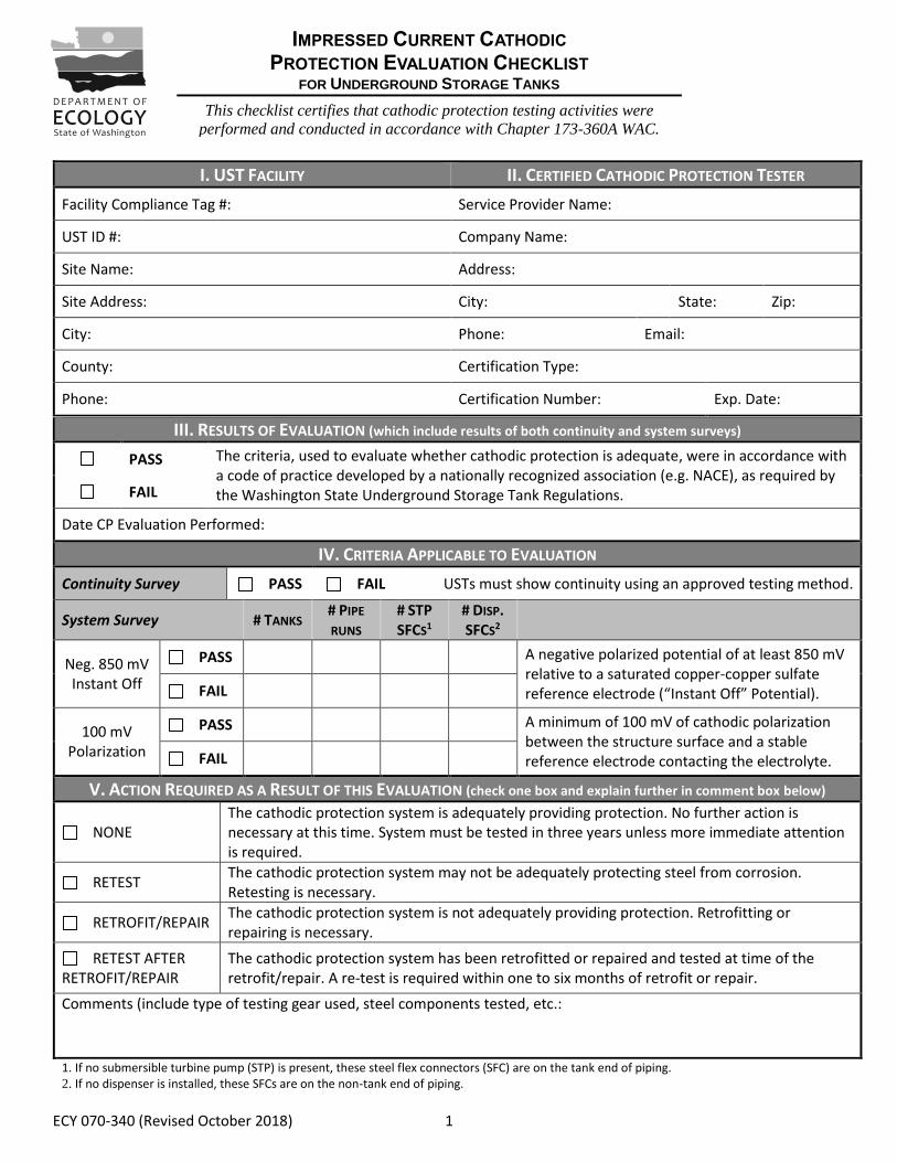
ECY 070-340 (Revised October 2018) 1 III. RESULTS OF EVALUATION (which include results of both continuity and system surveys) PASS The criteria, used to evaluate whether cathodic protection is adequate, were in accordance with a code of practice developed by a nationally recognized association (e.g. NACE), as required by the Washington State Underground Storage Tank Regulations. FAIL Date CP Evaluation Performed: IV. CRITERIA APPLICABLE TO EVALUATION Continuity Survey PASS FAIL USTs must show continuity using an approved testing method. System Survey # TANKS # PIPE RUNS # STP SFCS 1 # DISP. SFCS 2 Neg. 850 mV Instant Off PASS A negative polarized potential of at least 850 mV relative to a saturated copper-copper sulfate reference electrode (“Instant Off” Potential). FAIL 100 mV Polarization PASS A minimum of 100 mV of cathodic polarization between the structure surface and a stable reference electrode contacting the electrolyte. FAIL V. ACTION REQUIRED AS A RESULT OF THIS EVALUATION (check one box and explain further in comment box below) NONE The cathodic protection system is adequately providing protection. No further action is necessary at this time. System must be tested in three years unless more immediate attention is required. RETEST The cathodic protection system may not be adequately protecting steel from corrosion. Retesting is necessary. RETROFIT/REPAIR The cathodic protection system is not adequately providing protection. Retrofitting or repairing is necessary. RETEST AFTER RETROFIT/REPAIR The cathodic protection system has been retrofitted or repaired and tested at time of the retrofit/repair. A re-test is required within one to six months of retrofit or repair. Comments (include type of testing gear used, steel components tested, etc.: 1. If no submersible turbine pump (STP) is present, these steel flex connectors (SFC) are on the tank end of piping. 2. If no dispenser is installed, these SFCs are on the non-tank end of piping. I. UST FACILITY II. CERTIFIED CATHODIC PROTECTION TESTER Facility Compliance Tag #: Service Provider Name: UST ID #: Company Name: Site Name: Address: Site Address: City: State: Zip: City: Phone: Email: County: Certification Type: Phone: Certification Number: Exp. Date: IMPRESSED CURRENT CATHODIC PROTECTION EVALUATION CHECKLIST FOR UNDERGROUND STORAGE TANKS This checklist certifies that cathodic protection testing activities were performed and conducted in accordance with Chapter 173-360A WAC. Instructions are found on the back page.
Transcript of I. UST FACILITY II. C P
ECY 070-340 (Revised October 2018) 1
III. RESULTS OF EVALUATION (which include results of both continuity and system surveys)
PASS The criteria, used to evaluate whether cathodic protection is adequate, were in accordance with a code of practice developed by a nationally recognized association (e.g. NACE), as required by the Washington State Underground Storage Tank Regulations. FAIL
Date CP Evaluation Performed:
IV. CRITERIA APPLICABLE TO EVALUATION
Continuity Survey PASS FAIL USTs must show continuity using an approved testing method.
System Survey # TANKS # PIPE
RUNS # STP
SFCS1 # DISP. SFCS2
Neg. 850 mV Instant Off
PASS A negative polarized potential of at least 850 mV relative to a saturated copper-copper sulfate reference electrode (“Instant Off” Potential). FAIL
100 mV Polarization
PASS A minimum of 100 mV of cathodic polarization between the structure surface and a stable reference electrode contacting the electrolyte. FAIL
V. ACTION REQUIRED AS A RESULT OF THIS EVALUATION (check one box and explain further in comment box below)
NONE The cathodic protection system is adequately providing protection. No further action is necessary at this time. System must be tested in three years unless more immediate attention is required.
RETEST The cathodic protection system may not be adequately protecting steel from corrosion. Retesting is necessary.
RETROFIT/REPAIR The cathodic protection system is not adequately providing protection. Retrofitting or repairing is necessary.
RETEST AFTER RETROFIT/REPAIR
The cathodic protection system has been retrofitted or repaired and tested at time of the retrofit/repair. A re-test is required within one to six months of retrofit or repair.
Comments (include type of testing gear used, steel components tested, etc.:
1. If no submersible turbine pump (STP) is present, these steel flex connectors (SFC) are on the tank end of piping. 2. If no dispenser is installed, these SFCs are on the non-tank end of piping.
I. UST FACILITY II. CERTIFIED CATHODIC PROTECTION TESTER
Facility Compliance Tag #: Service Provider Name:
UST ID #: Company Name:
Site Name: Address:
Site Address: City: State: Zip:
City: Phone: Email:
County: Certification Type:
Phone: Certification Number: Exp. Date:
IMPRESSED CURRENT CATHODIC PROTECTION EVALUATION CHECKLIST
FOR UNDERGROUND STORAGE TANKS
This checklist certifies that cathodic protection testing activities were
performed and conducted in accordance with Chapter 173-360A WAC.
Instructions are found on the back page.
ECY 070-340 (Revised October 2018) 2
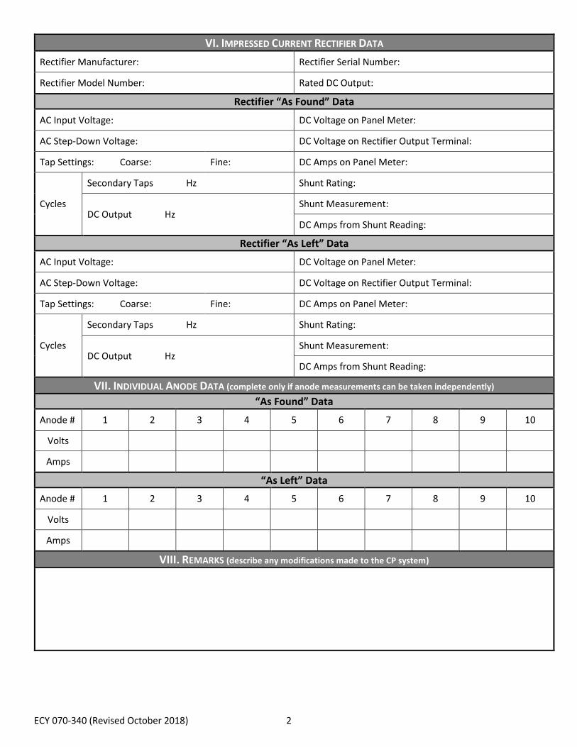
VI. IMPRESSED CURRENT RECTIFIER DATA
Rectifier Manufacturer: Rectifier Serial Number:
Rectifier Model Number: Rated DC Output:
Rectifier “As Found” Data
AC Input Voltage: DC Voltage on Panel Meter:
AC Step-Down Voltage: DC Voltage on Rectifier Output Terminal:
Tap Settings: Coarse: Fine: DC Amps on Panel Meter:
Cycles
Secondary Taps Hz Shunt Rating:
DC Output Hz Shunt Measurement:
DC Amps from Shunt Reading:
Rectifier “As Left” Data
AC Input Voltage: DC Voltage on Panel Meter:
AC Step-Down Voltage: DC Voltage on Rectifier Output Terminal:
Tap Settings: Coarse: Fine: DC Amps on Panel Meter:
Cycles
Secondary Taps Hz Shunt Rating:
DC Output Hz Shunt Measurement:
DC Amps from Shunt Reading:
VII. INDIVIDUAL ANODE DATA (complete only if anode measurements can be taken independently)
“As Found” Data
Anode # 1 2 3 4 5 6 7 8 9 10
Volts
Amps
“As Left” Data
Anode # 1 2 3 4 5 6 7 8 9 10
Volts
Amps
VIII. REMARKS (describe any modifications made to the CP system)
ECY 070-340 (Revised October 2018) 3
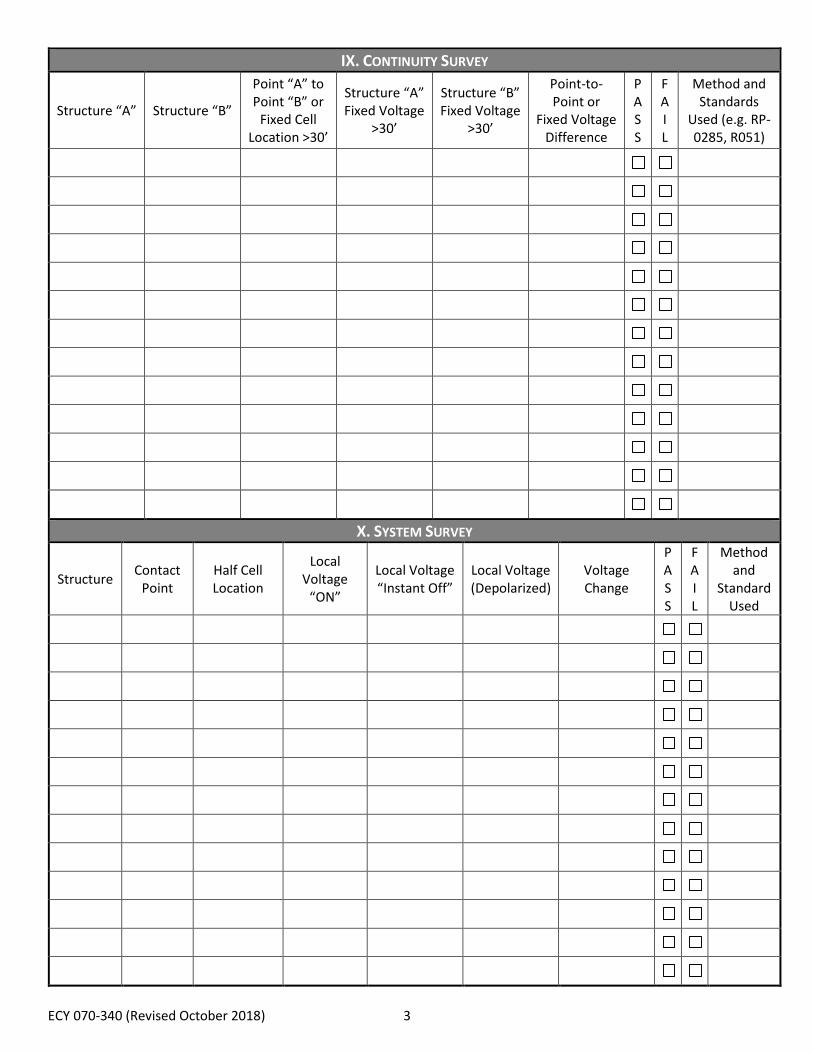
IX. CONTINUITY SURVEY
Structure “A” Structure “B”
Point “A” to Point “B” or
Fixed Cell Location >30’
Structure “A” Fixed Voltage
>30’
Structure “B” Fixed Voltage
>30’
Point-to-Point or
Fixed Voltage Difference
P A S S
FA I L
Method and Standards
Used (e.g. RP-0285, R051)
X. SYSTEM SURVEY
Structure Contact
Point Half Cell Location
Local Voltage
“ON”
Local Voltage “Instant Off”
Local Voltage (Depolarized)
Voltage Change
P A S S
FA I L
Method and
Standard Used
ECY 070-340 (Revised October 2018) 4
XI. UST SITE PLAN
Diagram the UST System, including tanks, piping, and dispenser locations, approximate scale, and any other notable structures/physical features. Indicate north with arrow. On the map below, include the half cell locations used during
testing. All test points must be easily identifiable, so that testing can be reproduced and your results verified.
ECY 070-340 (Revised October 2018) 5
XII. 60-DAY RECORD OF RECTIFIER OPERATION (a copy of this page must be provided to Ecology and the owner)
UST Owner/Operator UST Facility
Name: Name:
Phone: Address:
Email: City:
Rectifier Information
Rectifier Manufacturer: Rectifier Model Number:
Rated DC Output: Rectifier Serial Number:
Recommended Ranges (if amps or volts are zero or readings fall outside these ranges, contact the testing company immediately)
Volts: to Amps: to
Record of Inspections at least every 60 days (be sure to document any problems observed or when service provider is contacted)
Date Inspected
Rectifier Turned
On?
Tap Settings Volts Amps
Hour Meter (if present)
Operator Initials
Comments COURSE FINE
ECY 070-340 (Revised October 2018) 6
XIII. RETROFIT OR REPAIR DESIGN (if applicable)
All retrofitting or repairs to CP systems shall be designed by a Corrosion Expert. I certify that I am a Corrosion Expert qualified to engage in the practice of corrosion control on buried or submerged metal piping systems and metal tanks. I have
attached copies of the retrofit/repair design and of the Underground Storage Tank Retrofit and Repair Checklist.
Corrosion Expert’s Name: National Recognized Organization:
Company’s Name: Certification Number:
Corrosion Expert’s Signature: Date:
XIV. REQUIRED SIGNATURES
The service provider certifies the criteria used to evaluate whether cathodic protection is adequate were in accordance with a code of practice developed by a nationally recognized association (e.g. NACE), as required by the Washington State Underground Storage Tank Regulations.
Date Signature of Certified Cathodic Protection Tester Print or Type Name
Date Signature of Tank Owner or Authorized Representative Print or Type Name
ECY 070-340 (Revised October 2018) 7
INSTRUCTIONS
INSTRUCTIONS
This form must be submitted within thirty days of completing impressed current cathodic protection testing activities to
the following address:
Dept. of Ecology
UST Section
PO Box 47655
Olympia, WA 98504-7655
The attached Underground Storage Tank (UST) checklist is required for the activity above. Completing this checklist
documents and certifies cathodic protection testing activities were performed and conducted in accordance with
Chapter 173-360A WAC.
This checklist must be filled out completely by a certified cathodic protection tester, such as a corrosion expert with at
least a NACE CP3 certification or a tester holding a U4 Cathodic Protection ICC certification.
A copy of the completed form must be provided to the tank system owner/operator.
The owner/operator is responsible for submitting a copy to Ecology within 30 days of test date.
I. UST Facility: Complete this section about the facility where the cathodic protection system is being tested. If the
UST ID number is not known, include the facility compliance tag number.
II. Certified Cathodic Protection Tester: Complete this section about the UST service provider and service
provider company.
III. Results of Evaluation: The pass or fail refers to the overall evaluation of the cathodic protection system for the
entire UST system, including tanks, piping, and all steel flex connectors. Testing criteria shall be in accordance
with a code of practice developed by a nationally recognized association (e.g. NACE).
IV. Criteria Applicable to Evaluation: Choose criteria used to meet cathodic protection requirements by filling in
the number of tanks, piping runs, and steel flex connectors meeting (or failing) the specific criteria (note: the
standard chosen to meet the criteria shall be documented in the survey portions of this checklist).
a. Continuity Test: All impressed current UST systems (including associated piping and steel flex connectors)
shall be continuous to meet criteria to pass the continuity test.
b. -850 “Instant Off”: this can only be used if the current can be interrupted.
c. 100 mV Polarization: this can only be used if the current can be interrupted.
V. Action Required as a Result of this Evaluation:
a. None: The cathodic protection system is adequately providing protection. No further action is necessary at
this time. System must be tested in three years unless more immediate attention is required.
b. Retest: The cathodic protection system may not be adequately protecting steel from corroding. Retesting is
necessary.
c. Retrofit/Repair: The cathodic protection system is not adequately providing protection. Retrofitting or
repairing is necessary.
IMPRESSED CURRENT CATHODIC PROTECTION
EVALUATION CHECKLIST FOR UNDERGROUND STORAGE TANKS
ECY 070-340 (Revised October 2018) 8
d. Retest after Retrofit/Repair: The cathodic protection system has been retrofitted or repaired and tested at time
of the retrofit/repair. Testing is required again within one to six months after the retrofit/repair.
VI. Impressed Current Rectifier Data: Fill in all applicable information about the rectifier as first found and as last
left.
a. “As Found” Data: All readings and measurements are to be completed prior to making any rectifier
adjustments or prior to testing the cathodic protection system. This section should be completely filled in by
the tester.
b. “As Left” Data: All readings and measurements are to be completed after making any rectifier adjustments
or at the completion of testing the cathodic protection system. This section should be completely filled in by
the tester.
VII. Individual Anode Data: Complete this section only if anode measurements can be taken independently.
Certified.
VIII. Remarks: Describe any modifications that were made to the cathodic protection system.
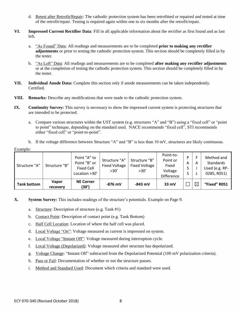
IX. Continuity Survey: This survey is necessary to show the impressed current system is protecting structures that
are intended to be protected.
a. Compare various structures within the UST system (e.g. structures “A” and “B”) using a “fixed cell” or “point
to point” technique, depending on the standard used. NACE recommends “fixed cell”, STI recommends
either “fixed cell” or “point-to-point”.
b. If the voltage difference between Structure “A” and “B” is less than 10 mV, structures are likely continuous.
Example:
Structure “A” Structure “B”
Point “A” to Point “B” or
Fixed Cell Location >30’
Structure “A” Fixed Voltage
>30’
Structure “B” Fixed Voltage
>30’
Point-to-Point or
Fixed Voltage
Difference
P A S S
FA I L
Method and Standards
Used (e.g. RP-0285, R051)
Tank bottom Vapor
recovery
NE Corner (30’)
-876 mV -843 mV 33 mV “Fixed” R051
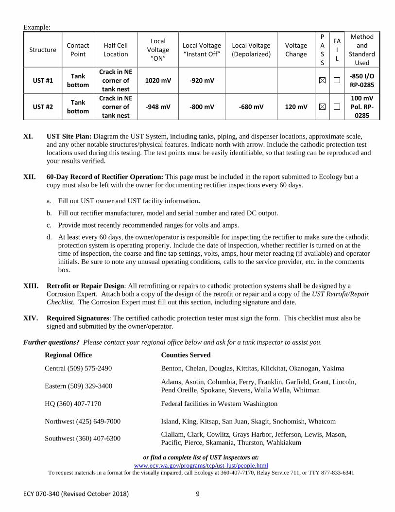
X. System Survey: This includes readings of the structure’s potentials. Example on Page 9.
a. Structure: Description of structure (e.g. Tank #1)
b. Contact Point: Description of contact point (e.g. Tank Bottom)
c. Half Cell Location: Location of where the half cell was placed.
d. Local Voltage “On”: Voltage measured as current is impressed on system.
e. Local Voltage “Instant Off”: Voltage measured during interruption cycle.
f. Local Voltage (Depolarized): Voltage measured after structure has depolarized.
g. Voltage Change: “Instant Off” subtracted from the Depolarized Potential (100 mV polarization criteria).
h. Pass or Fail: Documentation of whether or not the structure passes.
i. Method and Standard Used: Document which criteria and standard were used.
ECY 070-340 (Revised October 2018) 9
Example:
Structure Contact
Point Half Cell Location
Local Voltage
“ON”
Local Voltage “Instant Off”
Local Voltage (Depolarized)
Voltage Change
P A S S
FA I L
Method and
Standard Used
UST #1 Tank
bottom
Crack in NE corner of tank nest
1020 mV -920 mV -850 I/O RP-0285
UST #2 Tank
bottom
Crack in NE corner of tank nest
-948 mV -800 mV -680 mV 120 mV
100 mV Pol. RP-
0285
XI. UST Site Plan: Diagram the UST System, including tanks, piping, and dispenser locations, approximate scale,
and any other notable structures/physical features. Indicate north with arrow. Include the cathodic protection test
locations used during this testing. The test points must be easily identifiable, so that testing can be reproduced and
your results verified.
XII. 60-Day Record of Rectifier Operation: This page must be included in the report submitted to Ecology but a
copy must also be left with the owner for documenting rectifier inspections every 60 days.
a. Fill out UST owner and UST facility information.
b. Fill out rectifier manufacturer, model and serial number and rated DC output.
c. Provide most recently recommended ranges for volts and amps.
d. At least every 60 days, the owner/operator is responsible for inspecting the rectifier to make sure the cathodic
protection system is operating properly. Include the date of inspection, whether rectifier is turned on at the
time of inspection, the coarse and fine tap settings, volts, amps, hour meter reading (if available) and operator
initials. Be sure to note any unusual operating conditions, calls to the service provider, etc. in the comments
box.
XIII. Retrofit or Repair Design: All retrofitting or repairs to cathodic protection systems shall be designed by a
Corrosion Expert. Attach both a copy of the design of the retrofit or repair and a copy of the UST Retrofit/Repair
Checklist. The Corrosion Expert must fill out this section, including signature and date.
XIV. Required Signatures: The certified cathodic protection tester must sign the form. This checklist must also be
signed and submitted by the owner/operator.
Further questions? Please contact your regional office below and ask for a tank inspector to assist you.
Regional Office Counties Served
Central (509) 575-2490 Benton, Chelan, Douglas, Kittitas, Klickitat, Okanogan, Yakima
Eastern (509) 329-3400 Adams, Asotin, Columbia, Ferry, Franklin, Garfield, Grant, Lincoln,
Pend Oreille, Spokane, Stevens, Walla Walla, Whitman
HQ (360) 407-7170 Federal facilities in Western Washington
Northwest (425) 649-7000 Island, King, Kitsap, San Juan, Skagit, Snohomish, Whatcom
Southwest (360) 407-6300 Clallam, Clark, Cowlitz, Grays Harbor, Jefferson, Lewis, Mason,
Pacific, Pierce, Skamania, Thurston, Wahkiakum
or find a complete list of UST inspectors at:
www.ecy.wa.gov/programs/tcp/ust-lust/people.html
To request materials in a format for the visually impaired, call Ecology at 360-407-7170, Relay Service 711, or TTY 877-833-6341