I Simplified Lateral Torsional Buckling Equations for 1 ... · Simplified Lateral Torsional...
24
I I I I I I I I I I I I I I I I I RR3231 9186 Simplified Lateral Torsional Buckling Equations for 1- and Channel-Section Members by Donald W. White Professor Structural Engineering, Mechanics and Materials and Sc- Kwon Jung Graduate Research Assistant Structural Engineering, Mechanics and Materials Report o. 03-24a School of Civil and Environmental Engineering Georgia In stitute of Technology Atlanta, GA 30332-0355 e-mail: [email protected] Phone: 404-894-5839 FAX : 404-894-0278 March 2003
Transcript of I Simplified Lateral Torsional Buckling Equations for 1 ... · Simplified Lateral Torsional...

I I I I I I I I I I I I I I I I I
RR3231
9186
Simplified Lateral Torsional Buckling Equations for 1- and Channel-Section Members
by
Donald W. White Professor
Structural Engineering, Mechanics and Materials
and
Sc-Kwon Jung Graduate Research Assistant
Structural Engineering, Mechanics and Materials Report o. 03-24a
School of Civil and Environmental Engineering Georgia Institute of Technology
Atlanta, GA 30332-0355 e-mail: [email protected]
Phone: 404-894-5839 FAX: 404-894-0278
March 2003

I I I I I
I I I I I ·1
-I I I I
I I I I I
:1
.::::>
.::::> .... ~.J
I~O
.::::>
Simplified Lateral Torsional Buckling Equations for 1- and Channel-Section Members
DONALD W. WHITE and SE-KWON JUNG
Donald W. White is Professor, Structural Engineering, Mechanics and Materials, Georgia Institute of Technology, Atlanta, GA 30332-0355
Se-Kwon lung is Graduate Research Assistant, Structural Engineering, Mechanics and Materials, Georgia Institute of Technology, Atlanta, GA 30332-0355
INTRODUCTION
A wide variety of exact and approximate forms of the fundamental beam-theory equations for lateral-torsional buckling (L TB) of open-walled section members have been employed within modern steel design standards (CSA 200 I; AISC 1999 and 1989; AASI-ITO 1998; SAA 1998; SSRC 1998 and 1976; CEN 1993). The AISC (1999) LRFD Specification employs two parameters, denoted by XI and X2, in its statement of the clastic LTB resistance for doublysymmetric I-section members and channels. These parameters are a product ofa particular algebraic arrangement of the exact equations, but their physical ignificance is somewhat difficult to understand. Hoadley (199 I) shows that for rolled wide-flange shapes these terms can be approximated by simple functions of the flange thickness and section depth. I lowever, his approximations do not apply to general built-up I-shapes and channels. The AISC (1989) Allowable Stress Design Specification employs a traditional double-formula approximation for the clastic L TB strength. The double-fornlula approach is obtained by neglecting the contributions from the SI. Venant torsional rigidity Gl for deep narrow-flange sections, and by neglecting the contributions from the warping rigidity ECw for stocky shallow sections with relatively wide flanges. Generally, the member strength is taken as the larger value obtained from these two simplifications. Several approximations arc invoked in the development of these equations that also make them inappropriate for genera l built-up I-section members and channels. The AASHTO (1998) LRFD Specifications utilize another fornl of the exact doublysymmetric open-walled section beam-theory equations, specialized to I-section members. Although the AASHTO equations arc exact only for doubly-symmetric I-shapes, they arc employed as an approximation for the elastic L TB strength of singly-symmetric noncomposite 1-shapes with compact, noncompact or longitudinally-stiffened webs. Various other simplified expressions suggested in earlier developments can be found in (de Vries 1946), (Clarke and Hill 1960) and (SSRC 1976).
This paper presents a recommended simplified form of the fundamental beam-theory LTB equations for doubly-symmetric members, speciali zed to the clastic L TB resistance of 1- and channel-section members. This recommended form is exact for doubly-symmetric I-section members and has the advantage of improved accuracy relative to the corresponding AASHTO ( 1998) equations when applied to singly-symmetric I-shapes, including composite I-section members in negative bending. Also, it avoids significantly conservative errors that occur within the double-forn1Ula approach for a wide range of rolled wide-flange shapes. Furthennore, the physical significance of each of the terms within the simplified equations is easy to understand. These equations arc utilized as the base clastic LTB expressions within the AASHTO (2004) and AISC (2005) Specifications.
'!:O
I .~ .... "._' ·~o ......
I I I I I I I I I I I I I I I I I
I I
CO TEXT
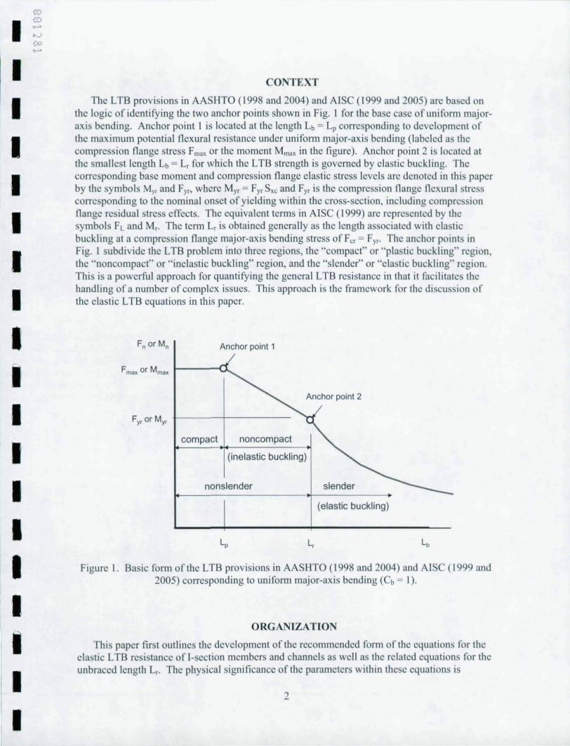
The L TB provisions in AASHTO (1998 and 2004) and AISC (1999 and 2005) arc based on the logic of identifying the two anchor points shown in Fig. I for the base case of unifoml majoraxis bending. Anchor point I is located at the length Lb = Lp corresponding to development of the maximum potential nexural resistance under unifoml major-axis bending (labeled as the compression nange stress F",ox or the moment Mmox in the figure). Anchor point 2 is located at the smallest length Lb = L, for which the L TB strength is governed by elastic buckling. The corresponding base moment and compression nange elastic stress levels arc denoted in this paper by the symbols M" and Fy" where M y, = Fyr S" and Fyr is the compression nange nexural stress corresponding to the nominal onset of yielding within the cross-section, including compression nange residual stress effects. The equivalent tenns in AISC (1999) arc represented by the symbols F Land M,. The term L, is obtained generally as the length associated with clastic buckling at a compression nange major-axis bending stress of Fe, = Fyr. The anchor points in Fig. I subdivide the L TB problem into three regions, the "compact" or "plastic buckling" region , the "noncompact" or " inelastic buckling" region, and the "slender" or "clastic buckling" region. This is a powerful approach for quantifying the general L TB resistance in that it facilitates the handling of a number of complex issues. This approach is the framework for the discussion of the clastic L TB equations in this papcr.
Anchor point 1
F mao< or Mma, 1----0...
Anchor point 2
F" orM" +-------~-----------
compact noncom pact
(inelastic buckling)
nonslender slender
(elastic buckling)
Figure 1. Basic form of the LTB provisions in AASHTO (1998 and 2004) and AISC (1999 and 2005) corresponding to unifornl major-axis bending (Cb = I).
ORGANIZATION
This paper first outlines the development of the recommended form of the equations for the clastic L TB resistance of I-section membcrs and channels as well as the related equations for the unbraced length L,.. The physical significance of the parameters within the e equations is
2

.::'
.Z,)
• .. ~ )" -)
'Co ~J
• • • • • • • •
• • • • • • • • •
explained, and the application of the equations to channel-section members is reviewed. Comparisons are then made to the corresponding AASHTO (1998) and AISC (1999) equations, to the traditional AISC double-formula expressions, and to severa l other possible alternative forms of the exact beam-theory solution . The main purpose of this paper is to present the advantages of the updated equations for doubly-symmetri c I-shapes and channel s. The companion paper (White and lung 2003a) addresses the application of these equations to singlysymmetric I-section members, including composite members in negative bending. Also, a simplified form of the exact beam-theory equations for singly-symmetric noncomposite I-section members is developed and evaluated in the companion paper.
DEVELOPMENT OF T HE RECOMMENDED FORM OF T HE ELASTIC L TB EQUATIONS
Timoshenko and Gere ' s (1961) fundamental equation for the clastic L TB strength of a doubly-symmetric I-beam can be expressed (for a general moment gradient case) as '
This equation can be writlen in the recommended form by first substituting
G= E 2(1 + v)
factoring the term ( ~~ r lye. outside of the radical, and perfonning some algebraic
manipulation of the resulting second term under the radi cal to obtain
' E fJC F =C ~v · y'- · (f b L2 S
b ,
I f the relationship
is substituted within the first occurrence ofCw under the radical in Eq. (3) , where
(I)
(2)
(3)
(4)
I The symbols utilized in this paper are the same as those employed within AASIITO ( I998 and 2004) unless noted otherwise,
3

I I I I I I I I I I I I I I I I I I I
for doubly - symmetric I - shapes
c = (5) for channels
is a "conversion factor" that allows the use of the samc L TB equation for both I-shapes and channels, and h is the distance betwecn the centroids of the flange elements, the elastic critical stress equation takes on the fonn
1+ I Jc ' L' 1t' (1 + v) S, h ff b
Finally, if one substitutes
r' ,
X' = S, h Jc
and 0.078 for the coefficient within the second tenn under the radical, Eq. (6) becomes
1t' E 0.078 , F" = Cb , I +--,-(Lb / r,t
(Lb / r,) X
For a doubly-symmetric I-shape, the parameter r,2 reduces to a basic familiar fonn if it is recognized that
h' l C ::::--'
w - 4
and this equation is substituted along with the definition
I , =--,
(d 12)
and the approximation
into Eq. (7a). The result is
4
(6)
(7a)
(7b)
(8)
(9)
(10)
(II)
I I I I I t I I I I I I I I I I I I I
(12)
or
(13)
where D is the depth of the web between the nange plates, d is the total section depth, Ar. = br,tr" Aw = Dt. , A., is the area of the web in nexural compression, equal to Dt"/2 for a doublysymmetric I-shape, and Afille, is the area of each of the four web-nange fillets. If d, hand Dare assumed to be approximately equal and the innuence of the web-nange fillet areas is neglected',
or if one considers that the product of the tenns D' < I and ( I + 6 Afill<l) > I is approximately hd A"
equal to one for all rolled I-shapes, Eq. (13) reduces to the radius of gyration of the compression nange plus one-third of the depth of the web in compression
b r ::: rc
,- 12( 1+~A.c) 3 Arc
( 14)
This parameter is employed within the AASIITO (1998) and AISC (1999) provisions for design of slender-web I-girders, although Eq. (14) is not explicitly stated within these pecifications.
Equation (8), with r, defined by Eq. (13), is for all practical purposes an exact representation of the fundamental elastic LTB strength. The only approximations invoked in writing Eq. (13) are the commonly-employed approximation associated with Eq. (9), the similar approximation of Eq. (II), and the assumption that the web-to-nange fillets are located at the bottom edge of the nange plates in the expression for I, in Eq. (12). For the complete set of ASTM A6 W shapes, the value of r, detennined from Eq. (13) is in all cases within plus or minus one percent of the exact value given by Eq. (7a). The simpler Eq. (14) gives accurate r, values that are less than one percent conservative relative to Eq. (7a) for beam-type W shapes with relatively narrow and relatively thin nanges (larger dlbr and btl2 tr). I lowever, it can be as much as 14 percent conservative relative to the exact Eq. (7a) for the heaviest column-type W shapes (small dib j and btl2tr). The largest error associated with Eq. (14) i for a WI4x808 section. The results are similar for welded shapes, where web-nange fillets are commonly not included in the section property calculations. For many plate girder type sections, the errors associated with the lise of Eq. (14) are negligible. The authors consider the additional complexity of including the temlS hid, D2/hd and Afill .. /A", in Eq. (13) to be small. Therefore, they prefer Eq. (\3) relative to Eq.
.2 The contribution of the web-flange fillet areas is commonly neglected for welded I-sections: however. the webnange fillet contributions are genera lly included in sec tion property tabtes for rolled shapes. such as in At C (2oot. & b).
5

I ,::;:> ,::;:> .~
'-' '::0
I '_J
I I I I I
I I
I I I I I I I
I I
I
(14). The advantage ofEq, (14) is its familiarity and physical significance relative to the AISC (1999) and AASHTO (1998) slender-web member provisions. Equation (7a) is a fundamental and exact expression for the r/ of doubly-symmetric I-shapes and channels. When Eq. (8) is employed for calculation of the elastic L TB resistance of rolled shapes, r, can be tabulated based on Eq. (7a) to simplify the calculations.
For doubly-symmetric I-section members, Eq. (8) is a particularly useful and understandable form for the elastic L TB resistance, expressed in tenns ofthc compression flangc major-axi s bending stress, All of the variables in this equation are well known in terms of their physical significance, and are readily available or easily calculated during the design process. Equation (8) shows that the fundamental clastic LTB strength is simply a function of the elastic modulus
E, the slenderness ~, the parameter X ' = S, h and the moment gradicnt modificr Cb. As r, Jc
stated above, the parameter C within the term X' is a "conversion factor." This tenn captures the unique attribute of channels associated with their elastic L TB resistance, aside from their lack of symmetry, namely the difference in Cw relative to that of an I-shape. The use of Eq. (8) for both 1- and channel-section member is based on the work by Hill (1954), Hill shows that the beamtheory elastic L TB equations for doubly-symmetric I-shapcs are applicable for channelmcmbers, given the proper calculation of Cw for a channel. It is important however to recognize that the bracing system for such a member must be designed to resist a significant moment associated with the tendency of the channel to twist about its shear center (SSRC 1976).
The parameter X2, equal to S, h for a doubly-symmetric I-section, has a particularly
J important physical significance, This term is the ratio of the bending and torsional efficiencies
of the cross-section, If the approximation d ~ h is used, this ratio simplifies to 21 , for these J
shapes. A shallow I-section (small S, and h) with wide stocky flanges (large J), will have a relatively small value for this term, whereas X2 is typically large for a deep I-section with relatively narrow flanges, In the context of Eq. (8), the design of rolled I-section members can be facilitated by providing tabulated values of this parameter. It should be noted that this tenn is always greater than one.
When the second term under the radical in Eq, (8) becomes negligible relative to one, this equation reduces to the form
(15)
Equation (15) is utilized in AASIITO (1998) and AISC (1999) for slender-web members. The use of this fom1 for these member types is motivated by its simplicity, the tendency of the second-term under the radical in Eq, (8) to be negligible for these types of members, and the fact that flange raking and the associated web distortion are more likely as the web slenderness becomes large (White and Jung 2003b).
6
I I I I I I I I I
I I I I I I I I I I
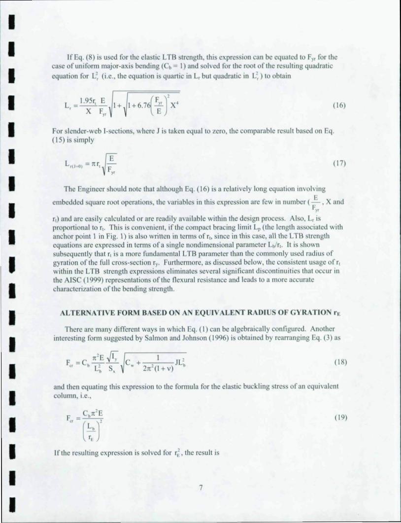
If Eq. (8) is used for the elastic L TB strength, this expression can be equated to FlT for the case of uniform major-axis bending (Cb - I) and solved for the root of the resulting quadratic equation for L', (i .e., the equation is quartic in L, but quadratic in L~ ) to obtain
( 16)
For slender-web I-sections, where J is taken equal to zero, the comparable result based on Eq. (15) i simply
L,p 0) = llr, ~ E FYT
( 17)
The Engineer should note that although Eq. (16) is a relatively long equation involving
embedded square root operations, the variables in this expression are few in number ( ~, X and F'T
r,) and are easily calculated or are readily available within the design process. Also, L, is proportional to r,. Thi is convenient , if the compact bracing limit Lp (the length associated with anchor point I in Fig. \) is also written in terms of r" since in this case, a\\ the L TS strength equations are expressed in terms of a single nondimensional parameter Lt/ r, . It is shown subsequently that r, is a more fundamental L TB parameter than the commonly used radius of gyration of the full cross-section ry• Furthermore, as discussed below, the consistent usage ofr, within the L TB strength expressions eliminates several significant discontinuities that occur in the AI C (1999) representations of the nexural resistance and leads to a more accurate characterization of the bending strength.
ALTERNATI VEFORl\1BA EDO A EQUIVALE TRADIU OF GYRATIO. r~
There are many different ways in whi h Eq. (I) can be algebraica\\y configured. Another interesting form suggested by Salmon and Johnson (\ 996) is obtained by rearranging Eq. (3) as
ll ' E ~ I 1 F" = C. -,- --., c. + , JL.
Lj, S, \I h -(I + v) (\ 8)
and then equating this expression to the fomlUla for the elastic buckling stress of an equivalent column, i.e.,
( 19)
If the resulting expression is solved for r,' , the result is
7

I I I I I I I I I I I I I I I I I
r: = F, C + I JL' = F, ~C + 0.039JL' E S, W 21t ' (I+v) b s, W b
(20)
Based on this equivalent radius of gyration, the elastic L TB strength always takes the form of Eq. (19), i.e., Euler's column buckling equation modified by Cb. At first blush, this appears to be a dramatic simplification. I lowever, this development is somewhat deceiving since the expression for r[ also contains the length Lb. The physical beam L TB behavior does not in general map all that well to the column elastic buckling equation. The authors prefer the forn1 given by Eq. (8), where the radical containing the contribution of the St. Venant torsional stiffness is included directly within the expression for the L TB resistance.
Equations (19) and (20) are useful for gaining a better understanding of several attributes of the elastic L TB equations however. For instance, a common practice is to neglect the contribution from St. Venant torsion to the elastic L TB resistance in certain cases, or in other words, to assume JLb' = 0 in determining the elastic L TB strength. As noted above, this assumption is invoked commonly for slender-web I-girders, partly since nange raking and the associated web distortion are more likely as the web slenderness becomes large] Also, this assumption is invoked typically in the development (or motivation) of equations for the length Lp corresponding to anchor point I in Fig. I, since the term 0.039 JLb' in Eq. (20) tends to be negligible relative to Cw for the short unsupported lengths associated with Lb = Lp. By taking JLb' = 0 in Eq. (20), the result is
COMPARI SO TO T HE AASHTO (1998) EQUATIONS FOR NO COM POSITE I-SECTIO S WIT H COMPACT, 0 COM PACT AND
LO G ITU DI ALLY-STIFFENED W EBS
(21 )
The AASHTO (1998) equations corresponding to Eq. (8) also are derived directly from Eq. (I) by substituting Eqs. (2) and (9) as well as the approximation of Eq. (II). The result, after some algebraic manipUlation, is
F = C 1tE ~ " b L S
b "
(22) '( h)' J -C 3.14E~ 1t - + - b
Lb (I +v) I " Lb S" 9.87(~)' + 0.769-
J
Lb I"
This expression (multiplied inappropriately by the hybrid girder factor Rh and expressed as the buckling moment Mer = RhFcrSxc) is specified in AASHTO (1998) to quantify the elastic LTB strength of noncomposite bridge I-beams and girders with compact, noncom pact and longitudinally-sti ffened webs .
Although Eq. (22) is strictly valid only for doubly-symmetric I-shapes, it is applied also for singly-symmetric nons lender-web I-girders in the AASHTO ( 1998) Specifications. The
1 The influence of web distortion on the L TB strengths is considered for general doubly- and singly-symmetric 1-section members in (White and Jung 2003b).
8

I '::::> '::::> , .... "'-)
':0
I '_'1
I ! I I
I I I I I I I I I I I I I I I
commentary of these Specifications states that Eq. (22) gives predictions within approximately 10 percent of the LTB equation for singly-symmetric I-section members provided in AISC ( 1999).
Equation (22) performs reasonably well for a large number of practical singly-symmetric 1-shapes. Ilowever, it exhibits significant errors relative to the beam-theory based L TB strengths in certain cases (White and Jung 2003a). This is in part due to the fact that changes in the size of the tension flange and web influence the L TB strength only through the tcnns S" , hand J in this equation. Equation (8) also may be applied as an approximation for the elastic L TB strength of singly-symmetric I-section members. White and Jung (2003a) show that this equation, with c = I, and r, calculated using Eq. (13) with Awe = Detw, generally gives a more accurate approximation of the exact open-walled section beam-theory solution than Eq. (22) for singlysymmetric I-section members.
Equation (8) also has another advantage relative to Eq. (22) by virtue of the fact that as either J or Lb approaches zero, r
F ' 0 = r, per Eq. (21). Therefore, Eq. (15) can be employed in the
P Lio '" )
development of expressions for the length Lp shown in Fig. I. Conversely, Eq. (22) is written most directly in tenns of the compression flange radius of gyration rye as
(23)
In the limit that Lb approaches zero, this equation becomes
(24)
Equation (8) is more fundamental in that the use of
(25)
gives the fundamental L TB form of Eqs. (15) and (19) for a doubly-symmetric I-shape in the
limit that 0.078{ ~: r becomes small relative to S,h ~ 21, (see the last term under the radical in
Eq. (8)). The reader should note that rye is the radius of gyration of the compression flange alone, equal to bfe, ,J 12 for a rectangular flange plate. This should be contrasted with the definition ofr, given by Eq. (14).
AASIITO (1998) does not specify an equation for the term L, in the context of its use of Eq. (22). Rather the AASHTO (1998) Specifications use the elastic L TB strength for all moment levels less than the yield moment My multipled by the hybrid girder factor Rh. The AASI-ITO (2004) provisions provide a more accurate representation of the L TB resistance by adopting the form shown in Fig. I.
9

'-'
I -z, ..... ,.j -:;0
-7'1
I I I I I I I I I I I I I I I I I I
COMPARISO TO THE AI C (1999) EQUATIO S FOR DOUBLY-SYMMETRIC 1- AND CHANNEL-SECTION MEMBERS
Two fonns of the exact beam-theory equations for elastic L TB of doubly-symmetric openwalled sections are specified in AIS (1999), Eq. (I) multiplied by S" and
M = cbs,x,.fi " Lb/ r,
where
X =~~EGJA 's 2 ,
and
x, = 4 Cw (~)2 - I GJ ,
1+ X;X, 2(Lb I r,)'
(26)
(27)
(28)
The primary reason for Eq. (26) is the use of LJ ry as a nondimensional slenderness parameter in writing the elastic L TB trength. The original fonn given by Eq. (I) is simpler. The authors recommend Eq. (8) as a simple L TB strength expression based on the slende rness LJ r, .
AISC ( 1999) gives a single expression for L" which is derived from Eq. (26) in a fashion similar to the development of Eq. (16) from Eq. (8):
(29)
As noted in the Introduction, the physical significance of the parameters X, and X2 is difficult to understand. The recommended alternative to this equation, Eq. (16), involves the three
E parameters -, X and r,. As discussed previously, the physical significance of each of these
F" parameters is easy to understand. Furthennore, the values for X2 and r, can be tabulated for standard I-shapes, similar to the tabulation of X, and X, in AISC (2001a and b).
In the limit that J or Lb approaches zero, Eq. (I) can be expressed directly as
, ~ F = C leE v·,. ... w
cr b L:! S b ,
By substituting Eq. (9), this equation may be written as
10
(30)

,~:>
I 'Zl ..... "--' ':'" --J
I I I I I I I I I I I I I I I I I I
, I 7t-E 2-
2 h _ C 7t ' E Ah M" = Cb --:,'-=- - b 2
Lj, S, (Lb / r, ) 2S, (31 )
Similar to the development in the previous section, Eq, (8) is more fundamental in that the use of
&s r=r . = r -'
I F(JI :;' ,-,() )' Ah (32)
gives the basic LTB form ofEqs, (IS) and (19) for a doubly-symmetric I-shape in the limit that
0.078{ ~,h )' becomes small relative to S, h " 21, in Eq. (8). The reader should note that ry is the
radius of gyration of the full doubly-symmetric cross-section. This term may be expressed as
b ,< for a rectangular flange plate. It is interesting to compare this expression to the
12( 1+ A,,) A,<
form given by Eq. (14) for r,.
One way in which the equations for Lp (the length corresponding to anchor point I in Fig. I) are often motivated is to replace the elastic modulus by the strain-hardening modulus Es within Eq. (31) (Galambos 1968; McGuire 1968; Salmon and Johnson 1996). This is based on the assumption that substantial plastic bending defonnations are developed throughout the crosssection prior to L TB. If Eqs. (24) or (31) are utilized within this context, an assumed value must
. A h Ah be mtroduced for the extraneous parameters -"- or -. Conversely, if Eq. (15) is employed
S" 2S, as the base equation, Lp can be expressed directly as (using Cb = I)
~' E
Lp =r, -mF,
(33)
where m is a multiple of the yield strength corresponding to the compression flange state within the heavily plastified cross-section. If the approximations Es = 0.03E and m = 1.12 are introduced, this expression becomes
Jf,-Lp = 0.5Ir, -F,
(34)
As discussed with the developments in (Galambos 1968) and (McGuire 1968), the unbraced length does not need to be restricted this severely for members to be able to develop substantial plasticity prior to the nominal strength being influenced by L TB. Futhennore, it should be emphasized that the above derivations are primarily for motivational purposes. The true physical aspects of the LTB response of heavily plastified members are significantly more complex than implied by the above idealizations. White and Jung (2004) show that the equation
II

,:n
I .z:, ,~ , . .)
':0
I ·:0
I I I I I I I I I I I I I I I I I
(35)
gives the best fit to the data for anchor point I from 277 experimental L TB tests of rolled and welded I-section members in uniform bending.
An important advantage of the use ofr, in the Lp equation is that it eliminates several discontinuities that occur within the AISC (1999) provisions. AISC (1999) Appendix F uses the radius of gyration of the compression /lange alone, rye, in writing the Lp limit for singlysymmetric I-section members. This results in an abrupt increase in Lp if a doubly-symmetric section is made slightly singly-symmetric. Appendix F of AISC (1999) uses ry within its Lp equation for doubly-symmetric I-shapes. Furthermore, Appendix G specifies r, for all types of slender-web I-sections. This results in a discontinuity in Lp as the web tran itions from a noncom pact to a slender element. Ifr, is employed for singly-symmetric I-section members that have the same web and compression /lange, but have larger tension /langes of various sizes, the Lp limit tends to decrease with increasing monosymmetry. This characteristic follows experimentally observed trends (White and Jung 2004; White and Kim 2004), which indicate that more restrictive limits are needed on the length Lp corresponding to Anchor Point I (Fig. I), for these types of members to have a simi lar level of reliability compared to other types of 1-section members. In addition, the fact that r, is associated solely with the compression portion of the I-section allows composite I-section members in negative bending to be handled in a simplified fashion using the same equations as for singly-symmetric I-section members . White and Jung (2003a) address this issue in more detail. Lastly, the use of r, in Eq. (35) is consistent with the use of the ratio MmoxlM« in the definition of un braced length limits comparable to Lp in the Canadian (CSA 200 I), Australian (SAA 1998), Eurocode (CEN 1993) and British (BSI 1990) Standards.
COMPARJ ON TO THE TRADITIONAL DOUBLE-FORMULA APPROACH FOR DOUBLY-SYMMETRIC I-SECTIO MEMBERS
As discussed in (SSRC 1976), Eq. (I) also may be written in the fomls
F = C. ll~EI , GJ ct Sxc Lb
1+ EC w ( ...::..)'
GJ Lb (36)
and
(37)
For shallow (small dlbr) and/or stocky cross-section members, the elastic L TB resistance is dominated by the St. Venant torsional stiffness and the value of the radical in Eq. (36) approaches unity. In this case, this equation, written in terms of moment, can be simplified to
12

I ,~
.::;> w~
, . .,l
.",
I '.0
I I I I I I I I I I I I I I I I I
(38)
Similarly, for deep (large d1br) thin-walled I-girders, the elastic L TB resi stance is dominated by the stiffness associated with the nonunifonn or warping torsion, and the radical in Eq. (37) approaches unity. In this case, Eq. (37), written in temlS of moment, can be simplified to
(39)
The traditional AISC ASD double-fonnula equations for the elastic L TB resistance of doublysymmetric I-section members are obtained by substituting the basic expressions for Iy, J and lye and introducing the additional approximations of: ( I) d ::= 2br and (2) tw::= 2tr/3. Equations (38) and (39) are retained here since they allow evaluation of the fundamental approximations of Cw/Lb2 = 0 and JLb2 = 0 in writing these equations. In the traditional ASD double-fonnula method, the elastic L TB resistance is taken as the larger of the values from these two approximations.
Figure 2 shows the nature of the above approximation in terms of the resulting predicted Me,/My at Lb = L~,,"CI)' where My is the yield moment FySxe, and L~mct) is based on Eq. (16) using Fy = 50 ksi (345 MPa) and F)" = 0.7Fy, as specified for doubly-symmetric non hybrid shapes in AASHTO (2004) and AISC (2005). The exact value of Me,/My is 0. 7 for a ll the members considered in this plot. The data points within Fig. 2 correspond to the complete set of ASTM A6 rolled wide-flange shapes listed in the AISC (200Ib) Shapes Database. Figure 3 shows the related approximations for the ratio of the approximate to the exact values ofL" L".ppmxYL"",ct), obtained using Eqs. (38) and (39) (by setting Fe< to 0.7 Fy and solving for the corresponding length). The following observations can be made from these plots:
• The fundamental errors in the double-formula based strengths are highly correlated with the parameter X2 of the recommended elastic L TB equations (8) and (16).
• The conservative approximation of L, associated with Eq. (38) is generally less than 10 percent for X2::: 350
• The conservative approximation of L, associated with Eq. (39) is generally less than 10 percent for X2 ~ 1500
• For values of X2 between 350 and 1500, the conservative errors in L, associated with the double-fomlUla approach are in general larger than 10 percent. The largest error is 2 1 percent (i.e ., L~.ppmx) = 0.79L~cxact) at X2 = 640, which is the value of this term where the L, values predicted based on Eqs. (38) and (39) are the same.
• Although the approximation of Eq. (38) is quite good for column-type wide-flange sections (i.e., dlbr ::= I) with the stockiest plate components, in general the use of this equation results in a signi ficant but needless conservative approximation of the true Me< or L, values.
13

':-D
I .:;> .... ,.._1 '.0
I ,~
I I I I I I I I I I I I I I I I I
0.7
0.6 .... _ .. ....... .,.. . 1i' ---.. ~ M 0.5 ~
1:"
""'''ttb ...J II 0.4 Da:u <tt>c=
.D c<no co ...J co c c .. 0.3 1 nl ,..
~ ..... 0.2 u ~ • Mer/My based on Eq. (39)
0.1 c Me,!My based on Eq. (38)
0 -1 0 500 1000 1500 2000 2500
Sxh/J
Figure 2. Ratio of the critical moment obtained from Eqs. (38) and (39) to the yield moment My at Lb equal to the exact va lue of L, from Eq. (16) for Fy, = 0.7Fy and Fy ~ 50 ksi (345 MPa) fo r the complete set of ASTM A6 W shapes. The exact Me,!My is equal to 0.7 for all the points in this plot.
1
0.8
1i' .. :l 0.6
:J -"..
M e ~ 0.4 ..
:J
0.2
o o 500
....... --~-........ - .. ~ .............
• L,(approx/Lr(exaet) based Eq. (39)
c Lr(approx/Lr(exaet) based on Eq. (38)
1000 1500 2000 2500
Sxh/J
Figure 3. Ratio of the values ofL, based on Eqs. (38) and (39) to the exact value from Eq. ( 16) fo r Fyr ~ 0.7 Fy and Fy ~ 50 ksi (345 MPa) for the complete set of ASTM A6 W shapes.
14

I I I I I I I I I I I I I I I I I
• Although the approximation by the use of Eq. (39) in the calculation of L, is less than 10 percent conservative for X' ~ 1500, the conservative error is still six percent at X' - 2500. Therefore, assuming that the reduction in the L TB resistance due to potential web distortion is not an issue, it can be concluded that Eq. (39) results in a significant and needless conservative error in the elastic L TB resistances. Also, the Engineer should note that for un braced lengths larger than Lb = L" the conservative error associated with the use of Eq. (39) is larger.
Figures 4 and 5 show the variation in Mc/My from Eqs. (38) and (39) at Lb = Lnc",.) versus the cross-section aspect ratio dibr for the complete set of all ASTM A6 W shapes. The signi ficance of the parameter d/br is that cross-sections that have a larger dibr tend to work more efficiently for problems involving nexure only, while cross-sections with dib, close to 1.0 tend to work better as columns. Figure 4 shows that even for column-type W sections (i.e., dibr ~ I), where Eq. (38) would tend to govern in the double-formula approach, the conservative error in using Eq. (38) can be greater than 10 percent. The more conservative predictions for a given dibr in Fig. 4 tend to occur for sections that have thinner nange and web plates. FurthernlOre, Fig. 5 shows that even for beam-type W sections with dibr> 3, the use of Eq. (39) alone can result in conservative errors that are larger than 50 percent. The more conservative predictions in this case tend to occur for sections that have highly stocky nanges. Also, it should be noted that the conservative error associated with the application of Eq. (15) to these types of rolled wide-nange sections is similar to that shown in Fig. 5.
The use of the single elastic LTB expression given by Eq. (8) is in general significantly more accurate, and in addition the usc of this equation is more straightforward compared to calculating the resistances from the two separate double-formula equations and then taking the larger of the two values. Also, it is relatively easy to understand the physical significance of the terms in Eqs. (8) and (16). Furthennore, these equations reduce naturally to the fonns generally employed for slender-web members, i.e., Eqs. (15) and (17), simply by taking J = O. Equations (15) and (17) should be used for slender-web members, where the innuence of the St. Venant torsional stiffness is typically small and web distortion effects are of a potential concern. Lastly, Eqs. (8) and (16) can be applied for all types of I-sections and channels, including composite I-section members in negative bending. This is not the case for the AASHTO (1998) lye-based equation or the AISC (1989) double-formula equations.
Appendix A evaluates when the simple Eq. (17) can be employed for L, with small (less than 10 percent) conservative error in terms of the cross-section dimensional parameters. As noted above, the conservative error associated with the use of J = 0 is generally larger for Lb> L,. Therefore, Eq. (8) should be used in general for calculating the elastic L TB strength of members with compact or noncompact webs.
SUMMARY
The elastic L TB strength of doubly-symmetric I-section members and channels can be expressed in the exact but simple and easily understood form given by Eq. (8):
F =C rr'E " b( Lb/ r,) '
15
(8)

I I I I I I I I I I I I I I I I I I
0 .7 .,
0 .6
V 0.5 • • J II 0.4 .., ...J - 0.3 IV ~
~ ..... 0 .2 u ~
0.1
0
0
-r::: a !lI flg l :: I ~ g _ 00 0 i!~ Q) 0 o
JJ e 0 R Q 0 me CJl ~ o 'I> 0 6'1J,,"QP aao ED "
o
1
alb Oh Dr:t}J ~ 0 0 % 0 B o Dar 0 % Q;b 0
Q 0 D- D~1'b 0 0 DO a -C QOO cP a 0 to 'b 0..rP a
o 0 DOlt! BD a "ot:tS(JIRI 00
a a n ~ ~~ nO o Q:lO Il
2
d/b,
00 'be ~ S: rF 0
3 4
Figure 4. Ratio of the critical moment obtained from Eq. (38) (based on neglecting the warping rigidity E w) to the yield moment My, at Lb equal to the exact value of L,. from Eq. (16) for Fl" 0.7Fy and Fy 50 ksi (345 MPa) for the complete set of ASTM A6 W shapes. The exact Mj My
is equal to 0.7 for all the points in this plot.
0 .7
0 .6 .+ ~ •• t ... • • .+ ~ 1 •••
I • • • •• : ;t • • • • , •• <
0 .5 , ..... ",. ... " •• •••• •• • · .. ... .. .... . J *'+ • • • • • • .. +.9#: •••• 0
0 0
II 0.4 0 0 0 • .+#+ ••• 0
00 - • J .. \ . : ....... • 0
~ 0 0 ..... - 0.3 0 0
IV ~ 0 0 00 00 0
0 o .. ~
l 0 0 .. 0
~ 0 0 00 ..
"""5 0 .2 00 0 •
~ • •
~ o· • 0 0
0 0 .1 0\ •
" 0
0 1 2 3 4
d/b,
Figure 5. Ratio oCthe critical moment obtained from Eq. (39) (based on neglecting the t. Vcnant torsional rigidity GJ) to the yield moment My, at Lb equal to the exact value of L,. from Eq. (16) for Fl" = 0.7Fy and Fy = 50 ksi (345 MPa) for the complete set of ASTM A6 W shapes.
The exact Me/My is equal to 0.7 for all the points in this plot.
16

I I I I I I I I I I I I I I I I I I I
.::;:>
.::;:> "~ )'._' .,,;)
'_'J
This equation shows that the elastic L TB resistance of these types of members depends on the moment gradient factor Cb, the elastic modulus E, the slenderness parameter Li/r" and the ratio
of the torsional and bending efficiencies of the cross-section X' = S, h . This last ternl reduces Jc
2l x approximately to -J- for a doubly-symmetric I-shape. All of these variables are well known in
ternlS of their physical significance, and are readily available or are easily calculated during the design process. The use ofEq. (8) in the design of rolled I-shapes and channels can be facilitated by tabulating the values of r, and X', where r, may be calculated exactly for doubly-symmetric 1-shapes and channels from Eq. (7a) and c is a conversion factor for channels given by Eq. (5). As discussed by White and lung (2003a), Eq. (8) can also be used as an accurate approximation for the elastic L TB strength of a wide range of singly-symmetric I-section members, including composite members in negative bending, but with r, given by Eq. (13). Equation (8) also has the advantage that it reduces to the elastic L TB equation for slender-web I-section members in AISC (1999) and AASHTO (1998) simply by substituting 1 = 0, i.e.,
F = C 1t ' E " b (Lb I r, )'
The un braced length corresponding to the transition from inelastic to elastic L TB corresponding to Eq. (8), L,., is given by Eq. (16):
L.= 1.95r, ~ 1+ 1+6.71FY'J' X4 X F,. '\ E
( 15)
( 16)
This equation is similar in fonn to the corresponding exact equation in AISC (1999) (Eq. (29», but is based on the more fundamental parameters discussed above. The comparable equation for slender-web members reduces to the particularly simple form given by Eq. (17):
( 17)
The above recommended equations are compared to various other exact and approximate forms for the elastic L TB strength of doubly-symmetric I-section members and channels. The paper shows that the radius of gyration r" given exactly by Eq. (7a) for doubly-symmetric 1-shapes and channels and closely approximated by Eq. (13) for I-section members, is more
fundamental to the L TB problem than ry or rye. In the limit that 0.078{ ~,b J ' becomes negligible
relative to Sxh ;: 21x in the last term of Eq. (8), the elastic L TB strength reduces to the fonn of Euler's column buckling equation, but with the radius of gyration taken as r, . Conversely, additional ternlS remain within the elastic L TB strength formulas at this limit when ry or rye are used.
17
------- - -- -----
I ,:;, .:::> .... '.J '.0
I I I I I I I I I I I I I I I I I I
The paper also shows that, although the traditional double-formula approach gives reasonable results at the extreme limits of shallow stocky colunm-type I-sections and deep narrow-flange beam-type I-sections. the two separate equations used in this approach give quite conservative answers for a large percentage of rolled I-shapes. The errors associated with the double-formula approach are strongly correlated with the bending to torsional efficiency ratio X2
Detailed assessment of the cross-section dimensional parameters for which the simplest approximate equation for L, (Eq. (17)) is less than I 0 percent conservative are evaluated in Appendix A. In general, the t. Venant torsional stiffness J should be included for accurate calculation of the elastic LTB resistance in compact- and noncom pact-web members for lengths larger than L,. This is because the conservative errors associated with the use of J - 0 are larger for increasing values of the unbraced length Lb.
The companion paper (White and Jung 2003a) considers an ad hoc extension of the recommended elastic L TB equations, similar in concept to the development and use of comparable elastic L TB equations for singly-symmetric I-shapes in AASIITO (1998). This ad hoc extension is useful since only one set of equations is then needed to handle all types of 1-section members and channels, including lateral buckling of the bottom flange of composite 1-section members in negative bending. The recommended equations give improved accuracy relative to the AASIITO (1998) equations for general I-shapes. The companion paper also develops and evaluates a simplified fonn of the exact beam-theory equations for singlysymmetric I-section members. onsiderations pertaining to the calculation of the St. Venant torsional tiffness J for general I-shapes as well as reductions in the elastic L TB resistance due to web distortion arc addressed by White and Jung (2003b).
ACKNOWLEDGEMENTS
This work was funded by Professional Services Industries, Inc. (PSI) and the Federal Highway Administration (FHWA). The financial support from these organizations is gratefully acknowledged. The opinions, findings and conclusions expressed in this paper are the authors' and do not necessarily reflect the views of the above organizations
REFERENCES
AASHTO (1998). AASHTO LRFD Bridge Design Specifications 2'''' Edition "'ith 1999, 2000 and JODI Interims, Amcrican Association of State and Highway Transportation Officials, Washington D.C.
AASHTO (2004). AASIITO LRFD Bridge Design Specifciations. 3'" Edilion, American Association of State and Ilighway Transportation Officials, Washington, D. .
AISC (2005). Specification/or Slruclllral Sleel Buildings, American Institute of Steel Construction, Chicago. IL (to appear).
AISC (200 I a). Manual of tcel Construction, Load and Resistance Factor Design, 3rd Ed., American Institute of Steel Con truction, Inc., Chicago, IL.
AISC (200Ib). Shapes Database, Version 3.01, American Institute ofStcel Construction, Chicago, I L.
18

.::> • ,z,
..... '-' '.0 'n •
• • • I I I I I I I I I
• '. I I
i l
AISC (1999). Load alld Resistance Factor Design Specification for StruclI/ral Steel Buildillgs, American Institute of Steel Construction, Chicago, IL, 292 pp.
AISC (I 989). Specification for Structural Steel Buildings: Allowable Stress Desigll alld Plastic Design, 9th Ed., American Institute of Steel Construction, Chicago, IL.
Clark, J.W. and Hill , H.N. (1960). "Lateral Buckling of Beams," Jou/"llal of the Structural Division, ASCE, 86(ST7), 175-196.
CE (1993). Eurocode 3: Desigll of Steel Structures, Part I. I - General Rules and Rulesfor Buildings, ENV 1992- 1-1 , European Committee for Standardization, Brussels, Belgium.
CSA (200 I). Limit States Design of Steel Structures, CAN/CSA-S 16-0 I , Canadian Standards Association, Toronto, Ontario, Canada.
de Vries, K. (1947). "Strength of Beams as Determined by Lateral Buckling," Trallsactions, ASCE, 112, 1245-1271.
Galambos, T.V. (1968). Stl"llctural Members and Frames. Prentice Hall , Englewood Cliffs, J, 373 pp.
Hill , H.N. (1954). "Latera l Buckling of Channels and Z-Beams," Transactiolls, ASCE, 11 9, p. 829.
Hoadley, P.W. (1991). " Practical Significance of LRFD Beam Buckling Factors," Journal of Structural Ellgilleerillg, 11 7(3),988-996.
McGuire, W. ( 1968). Steel Structures. Prentice I-Iall , N.J. , 111 2 pp.
SAA (1998). Steel Stl"llctures, AS41 00-1998, Standards Association of Australia, Australian Institute of Steel Construction, Sydney, Australia.
Salmon, e.G. and Johnson, lE. (I 996). Steel Structures, Design alld Behavior, 4th Ed., Prentice Hall , J, 1024 pp.
SSRC (1998). Guide to Stability Desigll Criteriafor Metal Structures, T.V. Galambos (ed.), Structural Stability Research Counci l, Wiley Interscience, New York, NY, 911 pp.
SSRC (1976) . Guide to Stability Design Criteria for Metal Stl"llctures, B.G. Johnston (ed.), Structura l Stabi lity Research Council, Wiley Intersc ience, New York, NY, 616 pp.
Timoshenko, S.P. and Gere, J.M. ( 1961). Theory of Elastic Stability, McGraw-llill , ew York, NY, 541 pp.
White, D.W. and Jung, S.-K. (2003a). "Simplified Lateral-Torsional Buckling Equations for Singly-Symmetric I-Secti on Members," Report 24b, School of Civil and Environmental Engineering, Georgia Insitutute of Technology, Atlanta, GA.
White, D.W. and Jung, S.-K. (2003b). "E ffect of Web Distortion on the Buckling Strength of Noncomposite Discretely-Braced I-Beams," Structural Engineering, Mechanics and Materials Report No. 24c, School of Civi l and Environmental Engineering, Georgia Insi tutute of Technology, Atlanta, GA.
White, D.W. and Jung, S.-K. (2004). "Unified Flexural Resistance Equations for Stability Design of Steel I-Section Members - Uniform Bending Tests," Structural Engineering, Mechanics and Materials Report No. 28, School of Civil and Environmental Engineering, Georgia Institute of Technology, Atlanta, GA.
19

I .~~ .:::> , ...... .. -~) . .0
I .""
I I I I I
I I I I I I I I I I I I I
White, D.W. and Kim, V.D. (2004). " Unified Flexural Resistance Equations for Stabi lity Design of Steel I-Section Members - Moment Gradient Tests," Structural Engineering, Mechanics and Materials Report No. 29, School of Civil and Environmental Engineering, Georgia Institute of Technology, Atlanta, GA.
APPENDIX A - CO SERVA TlVE ERROR ASSOCIATED WITH THE USE OF J = 0 IN CALCULATI G Lr FOR COMPACT- AND NO COMPACT-WEB I-SECTIONS
The parameter Lr is the unsupported length at the transition between the elastic and inelasti c L TB strength eurves in AASHTO (1998) and AISC (1999). As noted in the paper, the equations for Lr are derived in general by equating the base elastic L TB strength Fer to the compression flange stress corresponding to the onset of significant cross-section inelasticity, Fyr. Equation (16) is derived in this fashion based on the recommended general form for the elastic L TB resistance (Eq. (8», and Eq. (17) is obtained in this fashion from Eq. (15) for slender-web members, where J is taken equal to zero. Since Eq. (16) involves embedded square root operations, yet Eq. (17) is extraordinarily simple, it is interesting to investigate to what extent the inclusion ofa finite J in Eq. (16) increases the value of Lrrelative to that computed from Eq. (17). In this appendix, the percent difference between the L,. value determined by Eq. (16) compared to that determined by Eq. (17) is derived analytically.
One can observe that the ratio of the strengths predicted by Eqs. (8) and (15) depends solely
on the tern, 0~;8 (L. I r, ) ' inside the radical of Eq. (8). With some algebraic manipulation, the
ratio X2 can be expressed in terms of the nondimensional parameters Dlbrc, breltr" Dltw, and tn/tr, for a general I-shape as
(h / d)[(d 1 - Dl )b 'e + Dl t. J (h I d)[ {(d / D) l -I) + t. I b 'e J = X' = S" h
J 2(b 'e t re' + b . t . 1 + Dt w1 ) 2 [(t re I D)l + (b . I b re )(t . I D)l + (D / b rcl(t w I D) ' J
(40)
It should be noted that the final approximation in this equation is obtained by assuming
20

.::;:> • .::;:> ,~
".J . .0
• -..)
• I
• • • '. • • • • • • • • • • '.
d I h '" hI D = [ I + t r,~ 2 + t n ~ 2 ] (41 )
If Eq. (40) is substituted into Eq. (16) for X2, and then Eq. (16) is divided by Eq. (17), the result is a basic equation for the ratio of the L, values computed with and without the inclusion of J. Figure 6 shows a plot of the 10 percent conservative "error" curves in L, associated with the use ofEq. (17) instead ofEq. (16). That is, each of the curves in Fig. 6 gives the values of btltr and D/tw associated with 10 percent conservative error in L, for a given value of Dlbr. For each of the values of Dlbr, any points (D/tw, btltr) that fall above and to the right of the corresponding curve have conservative errors smaller than 10 percent. This figure is based on Fy = 50 ksi (345 MPa) and F)" = 0.7Fy, which is the specified value of Fy, for doubly-symmetric nonhybrid shapes in AASHTO (2004) and AISC (2005).
~
24
22
20
18
16
14
Error associated with the use of J = 0
( / is 'rs thi" 10 % in this region
-+-= I
i ... ...
I
--Olbf = 1.5 -- Olbf = 2 ....... Olbf= 2.5 -Olbf = 3 - Olbf = 3.5 ...... Olbf=4
'-""'~---:'--~+-":"-+-I-="""'- - Olbf = 6
80 120 160
Olt,.
- - ~
200
t r
240
Figure 6. Curves for 10 percent conservative error in L, associated with the use of J = 0, plotted as a function of D/br, btltr and D/tw based on Eqs. (16) and (17),
F)" = 0.7Fy, Fy = 50 ksi (345 MPa).
One can observe from Fig. 6 that for D/br ::: 3, D/tw ::: 50 and btltr ::: 11 (btl2tr= 5.5), the influence of J on the value ofL, is essentially always less than 10 percent. This is significant since many welded beam and girder type cross-sections will satisfy these limits. Even when
280
Dlbr = 2.5, which is likely to be smaller than the value of Dlbr for many welded I-girders, the error in L, associated with neglecting J is less than 10 percent essentially if btltr ::: 13 and D/tw::: 50. For Dlbr::: 3.5, the error in L, associated with the assumption of J = 0 is less than 10 percent ifbtltr::: 10 (or btl2tr::: 5) and D/t .. ::: 50. Therefore, practically speaking, the error in L,. associated with the use of J = 0 is less than 10 percent for 1110St bridge-girder type proportions. For larger Fy (and Fy,) values than those on which Fig. 6 is based, the horizontal portion of the 10
21

I .::::> .::::> .-,.J
'.0
I .:;0
I I I I I I I I I I I I I I I I I
percent error curves tends to shift downward, and the vertical portion of the curves for large O/br (e.g., Olbr= 6) tends to shift slightly to the right.
For rolled beam type wide-flange sections, it can be stated that the conservative error in Lr caused by using J = 0 will typically be greater than 10 percent, although not much greater for many light beam-type wide-flange sections. This can be inferred from Fig. 6, although it is not illustrated directly by the plot. Figure 5 shows however that for some beam-type wide-flange sections (e.g., sections with heavy flanges), the conservative error associated with the use of Eqs. (15) and (17) is substantial. Furthermore, Fig. 6 shows that for typical column type rolled or welded I-shapes, which tend to have O/br close to one and O/tw less than 50, the conservative error in Lr associated with the use of J = 0 is always larger than 10 percent. For many columntype cross-sections, thi s error is in fact significantly larger than 10 percent. This attribute is illustrated by the conservative nature of the curve for Lr(,ppro./Lr(mct) based on Eq. (39) for small
values ofX2 = S,h in Fig. 3. It is also illustrated by the small values for Mj My at Lb = Lr(cxoct) J
and d/br ;: I in Fig. 5. Figure 6 shows that for doubly-symmetric I sections with O/t" less than about 40, the increase in L, due to the St. Venant torsional rigidity is always greater than 10 percent.
Based on Fig. 6, it can be argued that it is often reasonable to neglect J in calculating Lr for welded I-girders. However, the error associated with the assumption of J = 0 becomes much larger for unsupported lengths larger than Lr. That is, for long unsupported lengths typica l of conditions which may exist during construction, the additional strength gained by the inclusion of J in Eq. (8) compared to that predicted by Eq. (15) based on J = 0 can be substantial. Therefore, it is recommended that in general Eqs. (8) and (16) should be utili zed in calculating the strength of compact- and noncompact-web I-section members. Use of Eq. (8) for Fer and Eq. (17) for Lr would lead to a di scontinuity in the clastic and inelastic LTB strength curves at the transition point, i.e., anchor point 2 in Fig. I.
APPENDIX B - NOTATION
A Total cross-sectional area, inl (mm2)
Arc Area of compression flange, inl (mm2)
Afil lel Area of each of the two web-ta-compression flange fillets, generally taken equal to zero for welded 1-shapes, inl (nun:!)
Aw Area of web, Dt ..... inl (111m2) AVoc Area of web in fl exural compression, Dctw. inl (mm2
)
Cb Moment-gradient factor for lateral-torsional buckling C .• , Warping constant, intI (mmb
)
D Depth of the web; clear distance between the flange plates, in (mm) Dc Depth of the web in compression; distance from the cross-section centroid to the inside face of the
compression flange, in (mm) E Modutus of elasticity of steel, 29 000 ksi (200000 MPa) E, Strain-ha rdening modulus of steel. ksi (M Pa) Fcr Elastic critical stress, ksi (MPa) Fma.( Maximum potential flexural resistance in temlS of the compression flange stress, ksi (MPa) Fn Nominal flexural resistance in ternlS of the compression flange stress, ksi (MPa) F, Specified minimum yietd stress, ksi (MPa) F)'f Compression flange flexural stress corresponding to the nominal onset of yielding at the extreme fibers in
compression or tension. including compression flange residual stress effects
22

I ':::l .:::l I"~
,--' 'J;)
I '.0
G I,
I I, 1,< J
I L,
Lp
I L,
M~
I M,
Mmax
M,
I MY' Rh S,
I S" X' Xl X,
I bf b" bn
I c d
h
I m
TI!
r,
I r, r",
I tf tf, tn tw
I V
I I I I I
Shear modulus of elasticity of steel. II 200 ksi (77 220MPa) Moment of inertia about the major axis of bending, in" (nlln") Moment of inertia about the minor-axis of bending, in" (mm4) Moment of inertia of the compression flange about the plane of the web, in" (mm4) St. Venant torsional constant, in" (0101
4)
Laterally unbraced length; length between points braced against lateral displacement of the compression flange. or between points braced to prevent twist of the cross-section, in (mm) Limiting laterally unbraced length to achieve the maximum potential flexural resistance of the section. unifornl moment case (Cb = 1.0), in (mOl) Limiting laterally unbraced length to ach ieve the onset of yielding in unifoml bending (C, = 1.0) at the extreme fibers in compression or tension, with consideration of compression flange residual stress effects. in (mOl)
Elastic buckling moment. kip-in (N-mm) Nominal flexural resistance, kip-in (N-mm) Maximum potential flexural resistance, kip-in (N-mm) Yield moment, FyS, = FyS,c = FyS,!, doubly-symmetric sections and channels bent about major axis; smaller of Myc and M ) h singly-symmetric sections bent abollt major axis, kip-in (N-mm) Yield moment capacity considering compression flange residual stress effects, FyrSxc. kip-in (N-mm)(?) Ilybrid girder h,ctor Elastic section modulus, doubly-symmetric sections and channels bent about major axis. inl (mm3
)
Elastic section modulus corresponding to the extreme compression fiber, inl (mm3)
Ratio of the bending to the torsional efficiency of the cross-section. specified by Eq. (7b) Beam buckling factor detined by AISC LRFD Specification (A ISC 1999) Equation FI-8 Beam buckling factor defined by AISC LRFD Specification (AISC 1999) Equation F 1-9 Flange width. doubly-symmetric I-shapes and channels. in (mm) Width of a rectangular compression flange. in (mill) Width of a rectangular tension flange. in (mm) Section factor associated with the elastic lateral-torsional buckling resistance of channels Total depth between the extreme fibers of the flange elements perpendicular to the major axis of bending, in (mOl) Distance between the centroids of the flange elements perpendicular to the major axis of bending. in (mm) A multiple of the yield strength corresponding to the compression fl ange state within a heavily plastified cross-section Equivalent column radius of gyration corresponding to elastic lateral-torsional buckling strength, in (mm) Radius of gyrat ion for lateral-torsional buckling defined by Eq. (7a) for doubly-symmetric I-shapes and channels and by Eq. ( 13) for doubly- or singly-symmetric I-shapes with rectangular flanges, in (mm) Radius of gyration about y axis. in (111m) Radius of gyration of the compression flange taken about the y axis, in (mm) Flange thickness, doubly-symmetric I-shapes and channels, in (mm) Compression flange thickness, in (111m) Tension flange thickness, in (mm) Web thickness, in (mm) Poisson's ratio of steel, 0.3
23