I-sim: An Instruction Cache Simulator · cache (and thus readily available for subsequent...
20
HEWLETT PACKARD I-sim: An Instruction Cache Si mula tor Donald O. Tanguay Jr. Software and Systems Laboratory HPL·92·11 January, 1992 caches, simulations As clock rates and instruction-level parallelism use increase, cache/memory systems will have difficulty efficiently handling the access demands for data and instructions. To gain some insight into the potential performance bottleneck of an overworked instruction cache, a fully parameterized instruction cache simulator has been created. This paper describes the simulator's modeling, implementation, and usefulness. © Copyright Hewlett-Packard Company 1992 Internal Accession Date Only
Transcript of I-sim: An Instruction Cache Simulator · cache (and thus readily available for subsequent...
rli~ HEWLETT~~ PACKARD
I-sim: An Instruction Cache Simulator
Donald O. Tanguay Jr.Software and Systems LaboratoryHPL·92·11January, 1992
caches, simulations As clock rates and instruction-level parallelism useincrease, cache/memory systems will have difficultyefficiently handling the access demands for data andinstructions. To gain some insight into the potentialperformance bottleneck of an overworked instructioncache, a fully parameterized instruction cachesimulator has been created. This paper describes thesimulator's modeling, implementation, and usefulness.
© Copyright Hewlett-Packard Company 1992
Internal Accession Date Only


1 Motivation
While technological developments continue, processor speeds are increasing. AB theuse of instruction-level parallelism increases, as in superscalar, superpipeline, andVLIW' architectures, more instructions are being issued per cycle. These twotrends lead to a greater demand for fast access to instructions and data. Becausepresent memory systems are unlikely to meet the increasing demand, they areviewed as a constraint in machine performance. Instruction cache performance isone of the crucial factors in determining ultimate machine performance, and, as anattempt to find a part of the solution, a trace-driven instruction cache simulatorhas been created.
The simulator's objectives are to examine and provide insight into instruction cacheperformance problems. With the basic block execution trace of a program (to beoutlined in section 3), the simulator serves as a tool for the easy collection ofstatistics for a variety of cache models. I-sim, the I-cache simulator, is composed ofthe instruction stream (Lstream) generator module and the cache module. In thisreport, after a general introduction to cache models, the details of the twosimulator components will be described, and a case study of the simulator's use willbe presented.
2 Cache Models
Because a working knowledge of caches is needed to guarantee a goodunderstanding of this paper, the following is a general introduction to cache models.This section may be skipped by the reader already familiar with cache models.
A cache is a small portion of memory used to temporarily store data or instructionsfor fast ' access, relying upon spatial' and temporal" locality for its effectiveness.Caches are physically divided into lines and sets, each line having a tag for
I Very Long Instruction Word' Small and fast are relative to main memory's size and latency, respectively.' Th e likelihood that the next contiguous address will be accessed.<Th e likelihood that the same address will be accessed again in the near future .
1

identification of data. Caches usually have four parameters giving them verydifferent behavior: associativity, number of sets, line size, and tag latency.
The first parameter is the associativity, the type of mapping a cache possesses.For example , any address can be mapped to 4 places in a cache with associativity of4. A direct-mapped cache (with associativity of I ), has every address mapped toonly 1 location.
The number of sets and line size, along with associativity, are the major factors indetermining a cache's size. The number of sets can be thought of as a cache's"height," while the line size, which is in multiples of a word, is the "width." Eachset contains a number of lines equal to the associativity, therefore, a cache's size isa ~~...r;oc iat il , i t,y x ..sei. s x lin es i ze,
The last cache parameters pertain to access time. The tag latency is the timerequired to decide if a certain address is present in the cache. For every query, thecache must consul t a number of tags equal to its associativity, leading to greatert ag latencies for caches with higher associativity. Hot words latency and updatelatency are two more access time parameters. They are not true cache parameters;rather, they describe the communication bandwidth between caches, and so wedefine these terms to describe the timing parameters of the cache/memory system.The hot word latency is the time after which the sought word is written into thecache (and thus re adily available for subsequent accesses ), and the update latencyis the additional time needed to write the rest of the line into the cache.
Caches are usually built into cache hierarchies, a multi-level system of caches inwhich main memory rests at the foundation (see Figure 1). Typically, travelingdown the hierarchy leads to caches which are bigger in size but slower in speed ,with main memory, the biggest and slowest, at the bottom.
Accessing an address in one cache, as in Figure La, is simple. After a time equal tothe tag latency, it is decided whether or not the address is present. If it is present a hit - the data at the address is available at an additional hot word latency later,and the access is finished for a total time of tl + hiol", If, however, the address isnot present - a miss - the access is more complicated. First of all, the addressmust be found in main memory, and after an additional time equal to mainmemory's latency, the hot word is written into the cache and is available for a totalaccess time of tl + mm /. Then, after main memory's update latency has elapsed, the
' We consi der a word to be the basic uni t of a cache; in thi s report, it is 32 bytes and can hold upto six instructions . We describe a hot word as the word con taining the instruction currently beingaccessed.
°In the following form ulas, l/ = tag laten cy. " wi = hot word latency, and mml = main memoryla tency.
2
A
lTI~t:ge!§1,9i1\*t;
I'liil il !itlI
111111111111111I
_IttlllllillB
PrefetchBuffer
il!llliillic
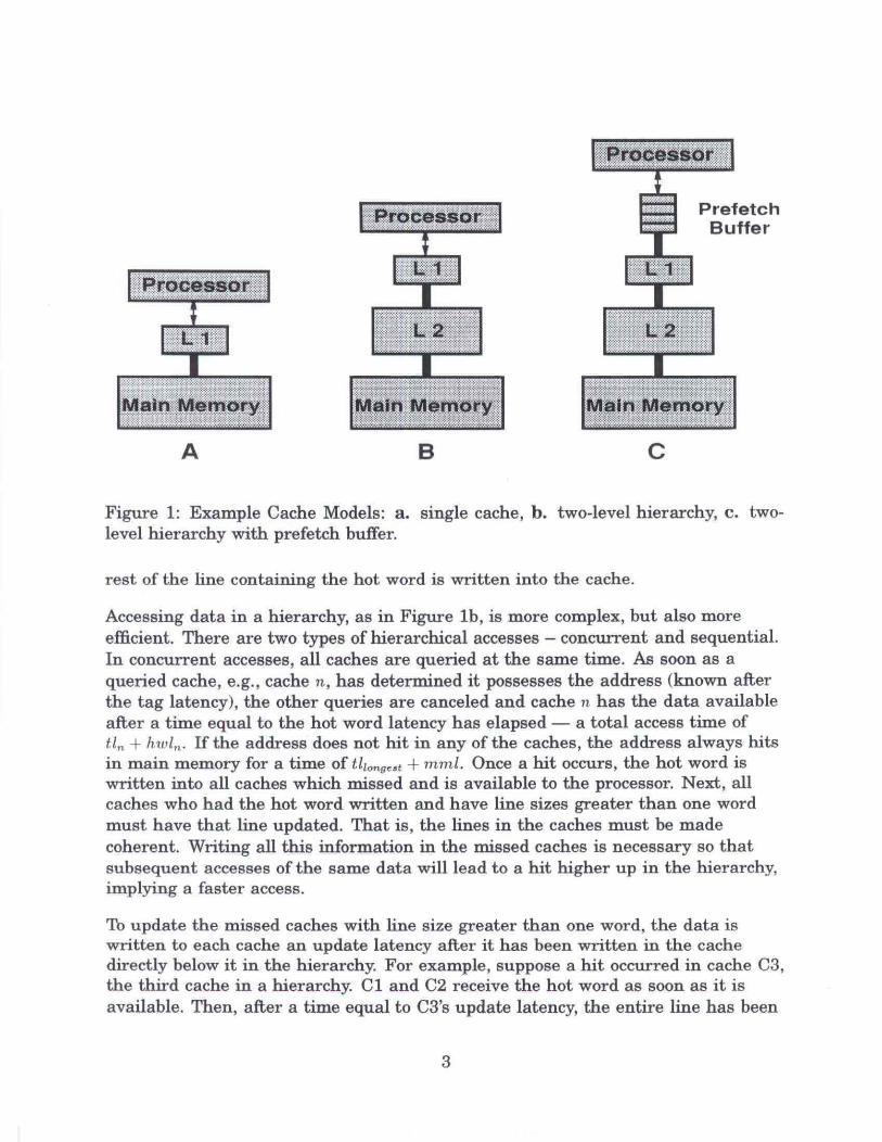
Figure 1: Example Cach e Models: a. single cache, b. two-level hierarchy, c . twolevel hierarchy with prefetch buffer.
res t of the line containing the hot word is written into the cache.
Accessing data in a hierarchy, as in Figure lb, is more complex, but also moreefficient . There are two types of hierarchical accesses - concurrent and sequential.In concurrent accesses, all caches are queried at the same time. As soon as aqueried cache, e.g., cache n , has determined it possesses the address (known afterthe tag latency), the other queries are canceled and cache n has the data availableafter a time equal to the hot word latency has elapsed - a total access time ofil « + lnol.; If the address does not hit in any of the caches, the address always hitsin main memory for a time of /.l/ ong,,' + rnml. Once a hit occurs, the hot word iswritten into all caches which missed and is available to the processor. Next, allcaches who had the hot word written and have line sizes greater than one wordmust have th at line updated. That is , the lines in the caches must be madecoherent. Writing all this information in the missed caches is necessary so thatsubseque nt accesses of the same data will lead to a hit higher up in the hierarchy,implying a faster access.
To update the missed caches with line size greater than one word, the data iswritten to each cache an update latency after it has been written in the cachedirectly below it in the hierarchy. For example, suppose a hit occurred in cache C3,the third cache in a hierarchy. Cl and C2 receive the hot word as soon as it isavailable . Then, after a time equal to C3's update latency, the entire line has been
3

written into C2. Now, after C2's update latency has passed, CI will have beenupdated, so that the entire cache/memory system has been updated fully and iscoherent.
Sequential accessing is a bit slower than concurrent accessing because the taglatencies add up with the number of misses. Starting at the fastest (and generallysmallest) cache, the address is queried for, and the answer is received in a timeequal to the cache tag latency. If the address is there, the data is available a hotword latency later for a total access time of ti l + hwll' If the address is not there,the next cache is checked, where, accordingly, the answer is known after a time ofII, . If the address is present, the data is ready at a total access time oftil + 1/, + hwl, . Otherwise, the other caches are checked in the same fashion. Wh enit appears that all n caches have misses, the data is taken from main memory for atotal time of 2::i=1il, +mml, worse than main memory alone! Update latenciesbehave the same way as in concurrent accessing.
Unlike random data accesses, an instruction stream for program execution exhibitsgreat spatial locality. A very good method of exploiting this locality is through theuse of a prefetch buffer, shown in Figure Ic, The prefetch buffer continuallyaccesses contiguous addresses in memory even before they are needed. Ideally,when a processor needs an instruction at a certain address, the prefetch buffer hasalready made it readily available by keeping ahead of the program's execution. Ofcourse, there is a limit to how much a prefeteh buffer can prefetch due to physicallimitations in size.
Lastly, when writing data into a cache, sometimes the data is mapped to a se talready full of other data; the old data must be removed. The rule to select whichdata gets bumped out of the cache is the replacement policy of the cache. Thecommon types of replacement policies are random, least recently used (LRU), andnot most recently used (NMRU). The first type removes a random word of data sothat the new one may takes its place. An LRU strategy selects the oldest data.Finally, NMRU is a mixture or the two; it randomly selects one from all but thenewest data. The current I-sim implementation uses a random replacementstrategy.
3 Overview of Simulation
The I-sim simulator is a breed of trace-driven simulations. As the name implies,the simulation is run according to a program's trace of executed instructions. For
4

trace compaction, however, I-sim has several additions to the general trace-drivensimulation. This section describes the simulator model and the methodology oftrace generation.
As a compaction technique, only the ID's of the basic blocks' visited are recorded ina trace, relying upon static information get the list of actual instructions executed .This complicates the simulation, but the advantage of smaller trace file size faroutweighs the additional complexity.
To gain this compaction benefit, I-sim has several additions to the generalt race-driven simulation - a stream generator, static information, and a buffer, asshown in Figure 2. First, the stream generator module reads the trace file for abasic block ill and then obtains the list of instructions contained in that basic blockby cons ulting the static information. The stream generator module then feed s thislist of instructions to the simulator module. As an implementation decision, abuffer is placed between the stream generator module and the simulator module toaccount for the lack of one-to-one correspondence between reading the trace file andconsuming the generated instructions.
DynamicTrace
1\11!!tlll"fll IIIJi&tt2i!r"j[Btiffer!
;\fjjjj,snitl~;I*jj1Stat i5 tic5iinfol'maHa'n;
Figure 2: Overview of l-sim simulation.
The trace generation methodology for I-sim is shown in Figure 3. Program sourcecode is compiled, resulting in the production of executable code and the extractionof static basic block information. The instrumented assembler code is executedeither with an actual machine or its simul ator, and a trace of the basic blocksvisite d is constructed. Code placement as signs addresses to each basic block. I-simfinally takes the trace and static information and performs the simulation of thecurrent I-cache model.
7We defin e a basic block as the largest portion of contiguous code in whi ch program executionca nnot branch out (excl uding subrou tine calls , which continue in memory di rectly after the ca ll wasmade ).
5
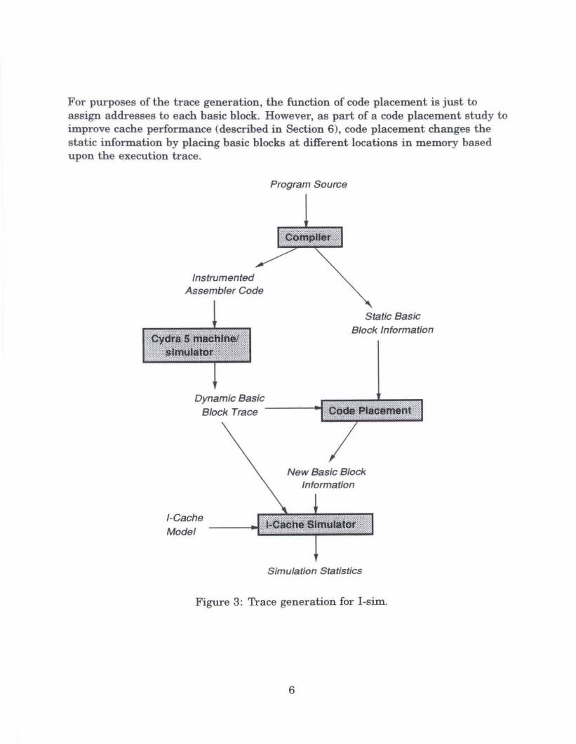
For purposes of the trace generation, the function of code placement is just toassign addresses to each basic block. However, as part of a code placement study toimprove cache performance <described in Section 6), code placement changes thestatic informat ion by placing basic blocks at different locations in memory basedupon the execution trace.
Program Source
InstrumentedAssembler Code
Static Bas icBlock Information
Dynamic Basic ..[~~;;m;U~"iil~fillIBlock Trace
New Basic BlockInformation
I-CacheModel ---1.lE~~~~~:lliillilLl
Simulation Statistics
Figure 3: Trace generation for l -sim,
6
4 I-Stream Generator
Like t he general t r ace-driven simulation model, l-sim h as two major components the instruction stream generator module and the instruction cache module, bothseparated by the I-stream buffer, a simple FIFO" queue. While the cache module ismodifiable, the I-stream module cannot be changed. Detailed descriptions of theI-stream module 's model and execution follow.
4.1 Model
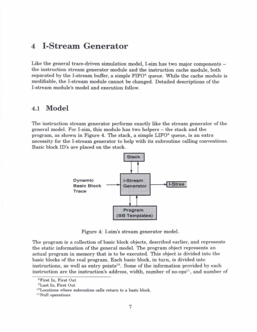
The instruction stream generator performs exactly like the stream generator of thegeneral model. For I-sim, this module has two helpers - the stack and theprogram, as shown in Figure 4. The stack, a simple LIFO· queue, is an extranecessity for the I-stream generator to help with its subroutine calling conventions.Basic block ID's are placed on the stack.
DynamicBasic B lockTra ce
I ;~!~~!;illil
~IIY~II'II HSttea&;,.. enera Ot",~1~:@&~1h.\~~~t~t]~~ttr
,f~III~'~I_tll\1l
Figure 4: I-sim's stream generator model.
The program is a collection of basic block objects, described earlier, and representsthe static information of the general model. The program object represents anactual program in memory that is to be executed. This object is divided into thebasic blocks of the real program. Each basic block, in turn, is divided intoinstructions, as well as entry points!". Some of the information provided by eachinstruction are the instruction's address. width, number of no-cps!", and number of
"Fi rs t In , First Ou t9 Last In . First Out
,oLoca tions where subroutine calls return to a basic block .II Null ope ra tions
7

dat a references.
The I-st rea m gener ator , given a trace, uses the stack and program to emi tinstructions, in the order they would be executed in hardware, and places thoseinstructions in the I-stream buffer.
4.2 Execution
To describe how the model works, an explanation of the I-stream generator'sexecu tion will be related through an execution snapshot.
The fir st step is to read one line of the program trace file , an even t triggered by theI-cache module when it needs more instructions in the I-stream buffer. The tracefile contains the order in which basic blocks were visited in a real execution of theprogram. With the current basic block identified, the basic block is searched in theprogram object, and its instructions are read and placed in the instruction streambuffer.
Reading instructions from a basic block starts at the appropriate entry point andcontinues until the end of the block, when the generator remains dormant until theI-cache module needs the I-stream buffer replenished. If, however, a subroutine callwas mad e in the current basic block, the present instruction position of the basicblock is placed on the stack and the next line of the trace file is read. Executiondoes not continue in the delayed basic block until a return instruction isencountered, in which case the top ofthe stack is popped off. Instructions from thispopped location to the end of the basic block are placed in the I-stream buffer, thusfinally finishing off this basic block which had been started before the subroutinecall. It is pos sible to have nested subroutine calls.
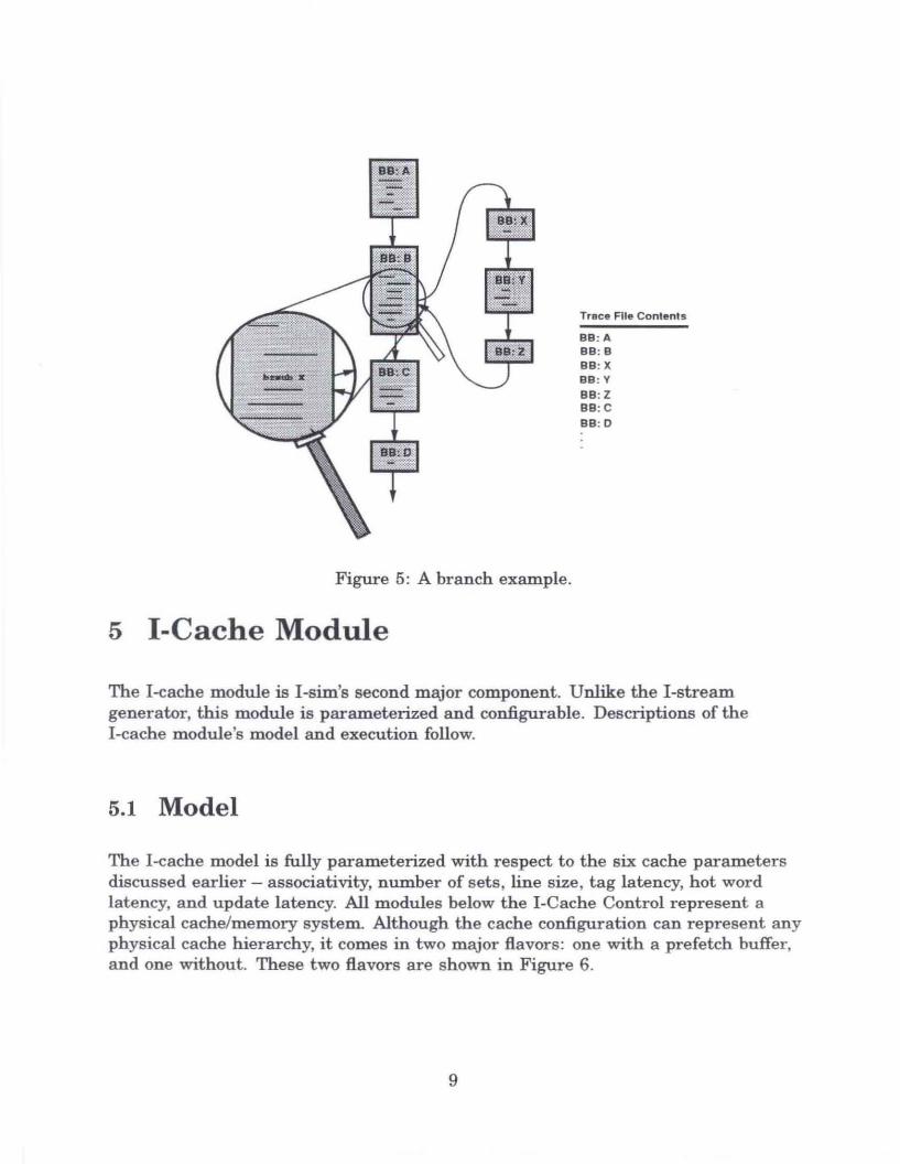
Figure 5 is an example of handling a subroutine call. Suppose BB:A was read fromthe trace file. Every instruction from BB:A gets placed in the stream buffer. Now,the trace file is read again, and BB:B's instructions are being put in the buffer.However, in the middle of BB :B there is a subroutine call, and the current posit ionis saved on the stack. The rest of BB:B's instructions are skipped for now, the tracefile is read, a nd BB:X's instructions are copied to the buffer. This continues unt ilone of the basic blocks (in this example, BB:Zl ends with a return instruction.When this happens, the trace file is not queried for the next basic block, but,inst ead, the next basic block on the stack is popped off and used (in this case.BB :Bl. The instructions left on it are taken, and reading the trace file continueswith the next block, now BB :C.
8
Trace File Co ntents
BB:ABB:BSS:XSS :YSS:ZSS:CSS:O
Figure 5: A branch example.
5 I-Cache Module
The I-cache module is I-sim's second major component. Unlike the I-streamgenerator, this module is parameterized and configurable. Descriptions of theI-cache module's model and execution follow.
5.1 Model
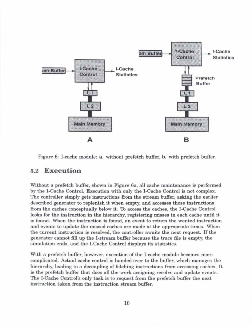
The l-cache model is fully parameterized with respect to the six cache parametersdiscussed earlier - associativity, number of set s, line size , tag latency, hot wordlatency, and update latency. All modules below the I-Cache Cont rol represent aphysical cache/memory system. Although the cache configuration can represent anyphysical cache hierarchy, it comes in two major flavors: one with a prefetch buffer,and one without. These two flavors are shown in Figure 6.
9
A
I-CacheStatistics
B
I-Cache
Statistics
PrefetchBuffer
Figure 6: I-cache module: a . without prefetch buffer, b . with prefetch buffer.
5.2 Execution
Without a prefetch buffer. shown in Figure 6a, all cache maintenance is performedby the I-Cache Cont r ol. Execution with only the I-Cache Cont r ol is not complex.The controller simply gets instructions from the stream buffer, asking the earlierdescribed generator to replenish it when empty, and accesses those instructionsfrom the caches conceptually below it. 'Ib access the caches, the I-Cache Controllooks for the instruction in the hierarchy, registering misses in each cache until itis found. When the instruction is found, an even t to return the wanted instructiona nd events to update the missed caches are made at the appropriate times. Whenthe current instruction is resolved, the con troller awaits the next request. If thegenerator cannot fill up the I-stream buffer because the trace file is em pty, thesim ul a tion en ds, and the I-Cache Contr ol displays its statistics.
With a prefetch buffer, however, execution of the I-cache module becomes morecomplica ted. Actual cache control is handed over to the buffer, which manages theh ier archy, leading to a decoupling of fetching instructions from accessing caches. Itis the prefetch buffer that does all the work assigning resolve and update events.Th e I-Cache Cont rol's on ly task is to reques t from the prefetch buffer the nextinstruct ion taken from the instruction stream buffer.
10
Unlike the I-Cache Control, which stops accessing words until an instruction in adifferent word is encountered, the prefetch buffer remains busy at all times,fetching even (now) unneeded words, in hopes that the instructions in them will beneeded in the future. As soon as one word has been resolved, the next word issought. This characteristic of the prefetch buffer leads to a great performanceadvantage in overall execution. The inner execution details of the prefetch bufferare described below.
The stream buffer, of arbitrary size, prefetches sequential code; this allows big winswith straight-through stretches of a program. Depending upon the size (inmultiples of a word), the stream buffer can hide the latencies of cache misses byfetching words before the instructions in them are needed, leading to smalleraccess delays. To adjust quickly when a branch occurs, the current word beingfetched is canceled and a new prefetching run begins at the new memory location.This prefetch buffer can hold as many different sequential code segments as its sizeallows. When a branch occurs, instead of flushing the entire buffer and beginninganew, the buffer begins a new segment. This is especially helpful when a smalliterating block' ? is encountered. If the iterator 's size can completely fit in theprefetch buffer and the iterator does not contain a procedure call, there will beabsolutely no misses for the loop's duration.
6 Case Study
In order to convey Lsim's capabilities, a case study will be presented. Due tounavailability of more rigorous benchmarks, an abridged version of the Linpackbenchmark was used. While Linpack normally processes a 100 by 100 matrix, our"Baby Linpack" processes only a 10 by 10 matrix. Though Baby Linpack has thesame code size as Linpack, the overall effect of scaling down the matrix was a bigreduction in loop iterations, resulting in a much smaller trace and, therefore, muchfaster simulation. Furthermore, the trace used included the setup code for Linpack,such as array initialization. When generally speaking of a benchmark, one isinterested only in the kernel of the program. For this reason, the results cannot beused in the sense of conventional benchmarking; however. it is still a legitimateprogram, containing many memory reads and writes and much scalar code . It'ssmall size is the major problem, but even this cannot hamper the visible effects of aprefetch buffer as it hides cache latencies during cold misses.
I'A segment of code that branches back to itself many times.
11

Three of Ivsim's abilities will be presented: profiling cache misses, studying theresults of a prefetch buffer, and examining different code placeme nt techniques. Noconclusions concerning particular cache models should be made from the results ofBaby Linpack.
6.1 Cache Miss Profiling
I-sim can record the number of misses in a cache over a period of time or over aperiod of instructions fetched. Figure 7 depicts an experiment with a 3-level cachehierarchy and shows the number of misses experienced by each cache within each2,OOO-instruction period. The LO, L1, and L2 caches were 32 bytes, 8K bytes, and256K bytes in size, respectively. This was a simulation of two executions of thebenchmark, explaining the absence of misses for the second half of the L1 and L2plots (the small size of Linpack allowed the entire program to be contained in L1and L2 after the first execution). Another visible phenomenon is the lack of missesin L1 and L2 for the period from 8,000 to 14,000 instructions. Linpack consistsmainly of heavily repeated loops , some of which were totally conta ined in L1 andL2 for this period.
LO
..12
"i 1 0
~ :,.... ..- ..- - i":~:
"*@ .... #. ~ =
i '7 W~j '* m· 6 r:w = ~ % ~8: *
».:~
'= ~~: ~~t~m #. n ~g,:,::" ~~: m -ij W~% g ~f: ~~~ ~~;
~:« .
1:~ ~":;?: ~ ~r~:::~; ::ij g ~§~ li t,::, W:::':~:::,,-,
L 1
L2
02 ••• 11111ZZZZZ:'O::J333 .......02 ••• 02 ••• 02 ••• 0 2 ••
:: I IIlm 11I ~~. OO-rm I
o :2 .. • .,...,.,.....,...1""'1 2. 2. a :I zL...".,...". ,...". .......- ."....,."....,.,.......,.,..."• .....,..-••oz ••• o z .... oa.e. oz ••
Figure 7: Cache miss profile for a 3-level hierarchy.
12

6.2 Initial Prefetch Buffer Experiment
To examine the effect of a prefetch buffer on l-cache performance, an initialprefetch buffer experiment was conducted. Two types of hierarchies werecompared. Both configurations had exactly the same Ll and L2 caches as well asmain memory; however, while the first had a cache-like, I-word buffer with aone-cycle latency, the other had a 4-word prefetch buffer with a one-cycle latency.Parameters of the lower caches and main memory were as follows:
Parameter Cache 1 Cache 2 Main Memory========================================================
associativity 1 8number of sets 128 256bytes per line 64 128tag latency 1 1h ot word latency 0 7 40update l a t e n c y 0 1 3
These cache hierarchies had the following preliminary results. For theconfiguration with the cache-like buffer, the total simulation time was 41,143cycles, and the total cache penalty was 5,515 - 13.4 % of the simulation time wasdelays due to cache stalls. For the hierarchy with the prefetch buffer, the totalsimulation time was 39,107 cycles, and the total cache penalty was 3,479 - 8.9 %of the time was due to cache stalls.
6.3 Initial Code Placement Experiment
An initial code placement experiment was conducted to compare three types of codepositioning: random placement, compiler (defaul t> basic block ordering, andprofile-guided code positioning. The "random" placement was actually an orde ringof increasing basic block ID numbers. The profile-guided placement was performedby Tin-Fook Ngai of Hewlett-Packard Laboratories and was based upon anexecution trace.
The following table shows the number of different transitions for each type ofpositioning. A sequential transition is a transition from one basic block to the onedirectly after it in memory, a loop transition is a segment of code branching back toitself, and a branch transition is from one place in memory to an unrelatedlocation. Loop and branch transitions are deleterious to l-cache performance
13

because they lead to poor locality. From the table, one can see that, though thecompiler did a nice job of default placement, it is the profile-guided placement thathas the most sequential transitions' ".
Basic Block TransitionsPlacement Transition Type Total
sequential branch loop Transitionsrandom 397 580 2791 3768
compiler (default) 663 314 2791 3768code profiling 880 97 2791 3768
For these three types of code placement methods, the following table shows thel-cache simulator's results. The model used did not have a prefetch buffer, becausewe wanted to localize the benefit of smooth transitions from the benefit of smoothaccesses across stretches of sequential code. From the initial results, it appearsthat Ngai's profile-guided code positioning performed the best, having smaller cachepenalty.
Cache Results
Placement Cache Total TotalLevell Level 2 Sim. Time Penalty
random 305 120 41715 6087compiler (default) 264 112 41143 5515
code profiling 226 106 40665 5036
7 Implementation Details
Efficiency of the simulator is highly dependent upon implementation. The followingdescribes some problems faced with I-sim's implementation and their solutions.
I-sim was developed in C++. A problem of HP's current implementation of C++ isthe lack of parameterized data types 14 . For the current I-sim implementation, this
13This information was provided by Ngai .I4This is soon to be corrected.
14

means there are three different types of FIFO queues (integer, instruction, andevent) instead of one parameterized FIFO queue. A parameterized data type can bean easy step towards code reduction.
The execution times of the simulator, one with the prefetch buffer and one without,are considerably different, even with all other parameters exactly the same. This isdue to the fact that the I-cache controller assigns cache events for every instructionwhile the prefetch buffer performs this for only every word. Because each word canhold up to six instructions, hierarchies without a prefetch buffer can have up to sixtimes more events and therefore execute much more slowly. Clearly, events are themain restraint in simulator performance.
Th somewhat alleviate this problem, the new and delete operators for the Eventclass were overloaded, as it was found that most of the execution time was inallocation. The overloaded operators reused a free list of Events wheneverpossible, rather than creating a new one every time. If the free list was not empty,the new operator would take an Event off the free list, returning a pointer to it.To replenish the free list, the delete operator tagged the unwanted Events to theend of the free list. This was a successful hack, but further methods for optimizingthe simulator should be found, as it is certain to contain further performancedeficiencies.
8 Future Work
Although I-sim can clearly show its worth in evaluating different I-cache modelsand in examining different methods of code optimizations, the simulator is, withoutdoubt, incomplete. Useful additions would aid the simulator in meeting itsobjectives and in making it more general-purpose. Some of the more helpfuladditions to the simulator and cache models are described below.
The author has recognized four major areas for improvement: augmenting thecache parameters, allowing for non-aligned instructions, introducing data conflicts.and extending the prefetch buffer.
Th increase l-sim's generality, further cache parameters should be added. Forexample, the current random replacement strategy could be extended to allow LRUand NMRU strategies. Furthermore, a user could have the option of placing a misscache or victim cache as part of another cache, giving even direct-mapped cachessome degree of associativity.
15

In the curren t I-sim implementation. every instruction is assumed to becache-a ligned. That is , every instruction is contained in one word alone, with nooverlapping into other words. Under the current implementation, when aninstruction is accessed, only the beginning address determines which word issough t . In the future, both the starling address and the ending address ne ed to beconsulted to allow non-aligned cases. If both addresses are contained in the sameword. then events are as before. If they are not in the same word, however, oneword may be a hit, while the other is a miss, or both are hits but are located indifferent caches. Determining the resolve time of the instruction clearly becomesmore complicat ed.
A downfall of many simulations is that they assum e an ideal world. A goodattempt at keeping l-sim'a feet on the ground would be to introduce the effects ofdat a accesses a mong instruction accesses. Often in a cache hierarchy, a lower-levelcache is shared by both the instructions and the data. A future I-sim needs t o havesuch conflicts of resources.
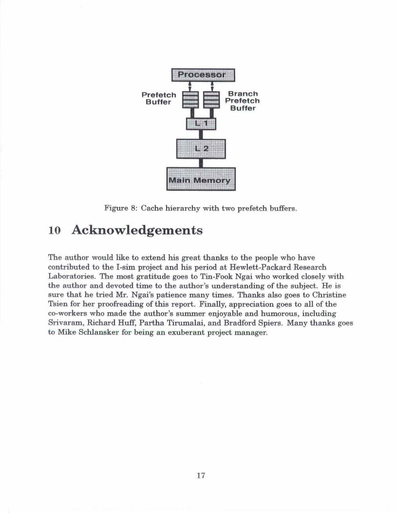
Finally, probably the best addition in terms of I-cache performance would be toextend the prefeteh buffer to branching. As seen in Figure 8, one prefetch bufferwould handle all sequential code while the other would handle branches todifferent memory locations. The sequential prefeteh buffer would perform as usual.but the branch prefetch buffer would operate only when given a branch hint. Thebranch prefeteh buffer would operate concurrently with the regular buffer within asmall t ime window (from when a branch hint is given to when the branch isactu ally taken). This would give the cache/memory system the a bility to hide cachemiss latencies not only in sequential code, but across branches as well.
9 Reflections
Over the course of this project, it has becom e very clear to the auth or thatprocessor efficiency is advancing at a much higher rate than tha t of memorysystems . Given great access demands, future cache/memory system performance isvery quest ionable and may lead to machine execut ion speeds well below potenti al.This simulator was built with this problem in mind. It is my hope that I-sim willbe a useful a nalytical tool and will provide helpful insight for possibleimprovements of I-cache performance.
16
PrefetchBuffer
BranchPrefetch
Buffer
illl~!IIIII!Figure 8: Cache hierarchy with two prefetch buffers.
10 Acknowledgements
The author would like to extend his great thanks to the people who havecontributed to the I-sim project and his period at Hewlett-Packard ResearchLaboratories. The most gratitude goes to Tin-Fook Ngai who worked closely withthe author and devoted time to the author's understanding of the subject. He issure that he tried Mr. Ngai's patience many times. Thanks also goes to ChristineTsien for her proofreading of this report. Finally, appreciation goes to all of theco-workers who made the author's smnmer enjoyable and humorous, includingSrivaram, Richard Huff, Partha Tirumalai, and Bradford Spiers. Many thanks goesto Mike Schlansker for being an exuberant project manager.
17