I NDEPENDENT LOGISTICS ASSESSMENT HANDBOOK …€¦ · · 2014-03-11I INDEPENDENT LOGISTICS...
108
I INDEPENDENT LOGISTICS ASSESSMENT HANDBOOK Department of the Navy Guide for Conducting Independent Logistics Assessments NAVSO P-3692 September 2006
Transcript of I NDEPENDENT LOGISTICS ASSESSMENT HANDBOOK …€¦ · · 2014-03-11I INDEPENDENT LOGISTICS...
I
INDEPENDENT
LOGISTICS
ASSESSMENT
HANDBOOK
Department of the Navy
Guide for Conducting
Independent
Logistics Assessments
NAVSO P-3692 September 2006


2
This page blank
3
Table of Contents FOREWORD .................................................................................................................................. 1 TABLE OF CONTENTS................................................................................................................ 3 INTRODUCTION AND SUMMARY OF CHANGES................................................................. 5 PART I: PLANNING AND ORGANIZING.................................................................................. 7
Objective...................................................................................................................................... 7 1.1 Process ................................................................................................................................... 7 1.2 Process Description................................................................................................................ 7
Step 1 - Select Team Leader. .............................................................................................. 7 Step 2 - Conduct Pre-Assessment Meeting......................................................................... 7 Step 3 - Select Team Members. .......................................................................................... 8 Step 4 - Announce ILA. ...................................................................................................... 8 Step 5 - Deliver Documentation. ........................................................................................ 9
1.3 Process Deliverables .............................................................................................................. 9 PART II - CONDUCTING THE ASSESSMENT........................................................................ 11
Objective.................................................................................................................................... 11 2.1 Process ................................................................................................................................. 11 2.2 Process Description.............................................................................................................. 11
Step 6 - Conduct Opening Meeting. ................................................................................. 11 Step 7 - Review Requirements/Capabilities. .................................................................... 12 Step 8 - Review Logistics Documentation/Planning. ....................................................... 13 Step 9 - Review Contractual Documentation.................................................................... 14 Step 10 - Review Master Schedule. .................................................................................. 14 Step 11 - Write and Compile Deficiencies. ...................................................................... 15
2.3 Process Deliverables ............................................................................................................ 15 2.4 Assessment Criteria ............................................................................................................. 15
1.0 ILS Management......................................................................................................... 17 2.0 Performance Based Logistics (PBL)........................................................................... 19 3.0 ILS Budgeting and Funding........................................................................................ 21 4.0 Design Interface .......................................................................................................... 23 5.0 Maintenance Planning................................................................................................. 29 6.0 Support Equipment ..................................................................................................... 31 7.0 Supply Support............................................................................................................ 33 8.0 Human Systems Integration (HSI).............................................................................. 35 9.0 Packaging, Handling, Storage and Transportation (PHS&T)..................................... 39 10.0 Configuration Management (CM) ........................................................................... 41 11.0 Product and Technical Data ...................................................................................... 43 12.0 Environmental, Safety and Occupational Health (ESOH)........................................ 45 13.0 Facilities/Infrastructure ............................................................................................. 49 14.0 Computer Resources and Software Support ............................................................. 53 15.0 Automated Information Technology (AIT) .............................................................. 55
PART III – ASSESSING AND REPORTING THE RESULTS.................................................. 57 Objective.................................................................................................................................... 57 3.1 Process ................................................................................................................................. 57

4
3.2 Process Description.............................................................................................................. 57 Step 12 – Assemble Draft Report ..................................................................................... 57 Step 13 – Brief Results to the Program Office. ................................................................ 58 Step 14 – Issue the Final Report. ...................................................................................... 58 Step 15 – Issue ILS Certification. ..................................................................................... 58
3.3 Process Deliverables ............................................................................................................ 58 PART IV - RESOLVING DEFICIENCIES ................................................................................. 59
Objective.................................................................................................................................... 59 4.1 Process ................................................................................................................................. 59 4.2 Process Description.............................................................................................................. 59
Step 16 – Tracking/Closing Actions. ................................................................................ 59 Step 17 – Close Assessment. ............................................................................................ 59
4.3 Process Deliverables ............................................................................................................ 59 APPENDIX A - DOCUMENTATION REQUEST LIST.......................................................... A-1 APPENDIX B - RELATIONSHIP BETWEEN RELIABILITY, AVAILABILITY, MAINTAINABILITY AND LOGISTICS ................................................................................. B-1 APPENDIX C - ILA DEFICIENCY/RECOMMENDATION FORMAT ................................. C-1 APPENDIX D - ILA REPORT FORMAT................................................................................. D-1 APPENDIX E - GLOSSARY OF TERMS .................................................................................E-1 APPENDIX F - GLOSSARY OF ACRONYMS ........................................................................F-1
5
Introduction and Summary of Changes This handbook was developed and coordinated through the DoN ILA Steering Group, which includes representatives from the Deputy Assistant Secretary Of The Navy (Logistics), Director, Chief of Naval Operations (Material Readiness and Logistics), Deputy Commandant of the Marine Corps (Installations and Logistics), Hardware Systems Commands, and Naval Supply Systems Command. The DoN ILA Steering Group is responsible for the content and management of this handbook. Users of the handbook are invited to send suggested improvements to the handbook and/or the ILA process (including: changes, updates, additions and deletions) to their respective Systems Command Steering Group representative for future consideration. This handbook provides detailed guidance to facilitate a comprehensive evaluation of the adequacy of ILS planning, management, control, execution and resources. The handbook also defines assessment criteria to be used at Initial Operational Capability (IOC) and Full Operational Capability (FOC) reviews. The methods and checklists in this handbook were designed to implement the requirements of SECNAVINST 5000.2 Series and SECNAVINST 4105.1 SERIES, emphasizing the Fleet as the ultimate customer of the acquisition process. SECNAVINST 5000.2 Series requires that the logistics support strategy shall be assessed, developed and integrated concurrent with the capability to ensure that short-term logistics support will be in-place at system IOC. Logistics support shall be sufficient, starting at IOC, to sustain operations to Capability Development Document/Production Document (CDD/CPD) specified levels of performance and affordability. Long-term logistics support shall be in-place at system FOC to maximize readiness and minimize life-cycle cost. Per SECNAVINST 4105.1 Series, “ILA and Certification Requirements,” individual Program Executive Officers (PEOs) and Systems Command (SYSCOM) Commanders are responsible for ensuring that an ILA is accomplished on all ACAT programs prior to Milestones B, C and the Full Rate Production (FRP) decision. They should also ensure a review of the status of ILS elements occur prior to IOC and FOC. The PEO or SYSCOM Commander (or designated representative) shall certify the status of the ILS program prior to the milestone decision and base the certification on the results of the ILA as documented in a formal, written report. While the assessment process is designed to provide input to the Milestone Decision Authority (MDA), the ultimate result of this process is to continuously improve supportability and reduce the cost of equipment and weapons systems delivered to the Fleet. Because of this, the timeframe between assessments should never exceed five years. If the timeframe between milestones surpasses five years, an ILA should be conducted prior to the five-year mark and coincide with major systems engineering reviews such as the Critical Design Review or Production Readiness Review (PRR). This is especially true for ship programs where the period between Milestones B and C may exceed ten years.
6
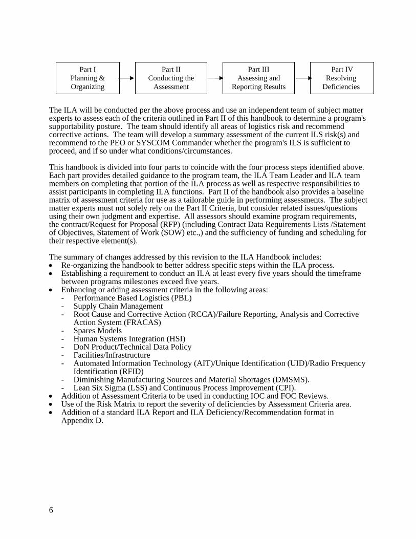
The ILA will be conducted per the above process and use an independent team of subject matter experts to assess each of the criteria outlined in Part II of this handbook to determine a program's supportability posture. The team should identify all areas of logistics risk and recommend corrective actions. The team will develop a summary assessment of the current ILS risk(s) and recommend to the PEO or SYSCOM Commander whether the program's ILS is sufficient to proceed, and if so under what conditions/circumstances. This handbook is divided into four parts to coincide with the four process steps identified above. Each part provides detailed guidance to the program team, the ILA Team Leader and ILA team members on completing that portion of the ILA process as well as respective responsibilities to assist participants in completing ILA functions. Part II of the handbook also provides a baseline matrix of assessment criteria for use as a tailorable guide in performing assessments. The subject matter experts must not solely rely on the Part II Criteria, but consider related issues/questions using their own judgment and expertise. All assessors should examine program requirements, the contract/Request for Proposal (RFP) (including Contract Data Requirements Lists /Statement of Objectives, Statement of Work (SOW) etc.,) and the sufficiency of funding and scheduling for their respective element(s). The summary of changes addressed by this revision to the ILA Handbook includes: • Re-organizing the handbook to better address specific steps within the ILA process. • Establishing a requirement to conduct an ILA at least every five years should the timeframe
between programs milestones exceed five years. • Enhancing or adding assessment criteria in the following areas:
- Performance Based Logistics (PBL) - Supply Chain Management - Root Cause and Corrective Action (RCCA)/Failure Reporting, Analysis and Corrective
Action System (FRACAS) - Spares Models - Human Systems Integration (HSI) - DoN Product/Technical Data Policy - Facilities/Infrastructure - Automated Information Technology (AIT)/Unique Identification (UID)/Radio Frequency
Identification (RFID) - Diminishing Manufacturing Sources and Material Shortages (DMSMS). - Lean Six Sigma (LSS) and Continuous Process Improvement (CPI).
• Addition of Assessment Criteria to be used in conducting IOC and FOC Reviews. • Use of the Risk Matrix to report the severity of deficiencies by Assessment Criteria area. • Addition of a standard ILA Report and ILA Deficiency/Recommendation format in
Appendix D.
Part II Conducting the
Assessment
Part III Assessing and
Reporting Results
Part IV Resolving
Deficiencies
Part I Planning & Organizing
7
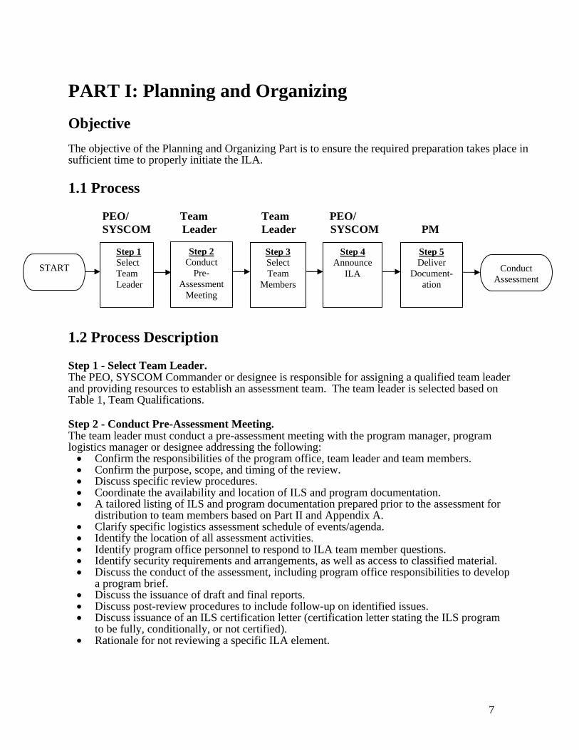
PART I: Planning and Organizing Objective The objective of the Planning and Organizing Part is to ensure the required preparation takes place in sufficient time to properly initiate the ILA. 1.1 Process PEO/ Team Team PEO/ SYSCOM Leader Leader SYSCOM PM 1.2 Process Description Step 1 - Select Team Leader. The PEO, SYSCOM Commander or designee is responsible for assigning a qualified team leader and providing resources to establish an assessment team. The team leader is selected based on Table 1, Team Qualifications. Step 2 - Conduct Pre-Assessment Meeting. The team leader must conduct a pre-assessment meeting with the program manager, program logistics manager or designee addressing the following: • Confirm the responsibilities of the program office, team leader and team members. • Confirm the purpose, scope, and timing of the review. • Discuss specific review procedures. • Coordinate the availability and location of ILS and program documentation. • A tailored listing of ILS and program documentation prepared prior to the assessment for
distribution to team members based on Part II and Appendix A. • Clarify specific logistics assessment schedule of events/agenda. • Identify the location of all assessment activities. • Identify program office personnel to respond to ILA team member questions. • Identify security requirements and arrangements, as well as access to classified material. • Discuss the conduct of the assessment, including program office responsibilities to develop
a program brief. • Discuss the issuance of draft and final reports. • Discuss post-review procedures to include follow-up on identified issues. • Discuss issuance of an ILS certification letter (certification letter stating the ILS program
to be fully, conditionally, or not certified). • Rationale for not reviewing a specific ILA element.
Step 1 Select Team Leader
Step 2 Conduct
Pre-Assessment
Meeting
Step 4 Announce
ILA
Step 5 Deliver
Document- ation
Step 3 Select Team
Members
Conduct Assessment
START
8
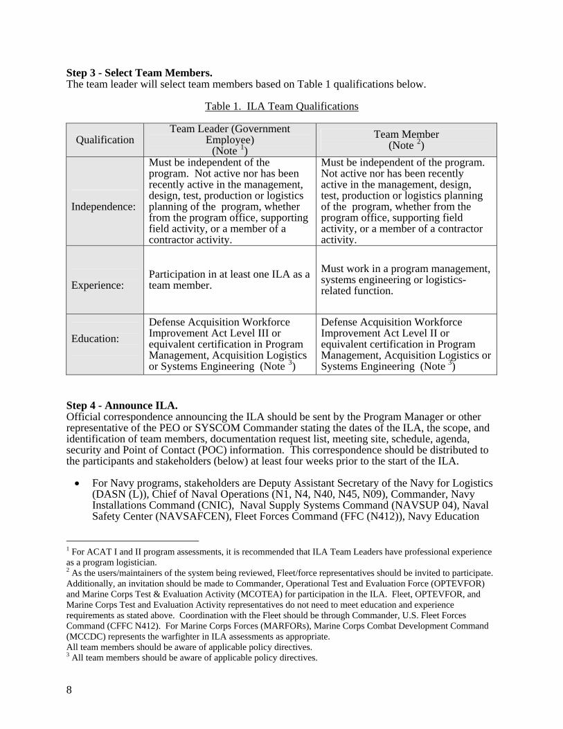
Step 3 - Select Team Members. The team leader will select team members based on Table 1 qualifications below.
Table 1. ILA Team Qualifications
Qualification Team Leader (Government
Employee) (Note 1)
Team Member (Note 2)
Independence:
Must be independent of the program. Not active nor has been recently active in the management, design, test, production or logistics planning of the program, whether from the program office, supporting field activity, or a member of a contractor activity.
Must be independent of the program. Not active nor has been recently active in the management, design, test, production or logistics planning of the program, whether from the program office, supporting field activity, or a member of a contractor activity.
Experience:
Participation in at least one ILA as a team member.
Must work in a program management, systems engineering or logistics- related function.
Education:
Defense Acquisition Workforce Improvement Act Level III or equivalent certification in Program Management, Acquisition Logistics or Systems Engineering (Note 3)
Defense Acquisition Workforce Improvement Act Level II or equivalent certification in Program Management, Acquisition Logistics or Systems Engineering (Note 3)
Step 4 - Announce ILA. Official correspondence announcing the ILA should be sent by the Program Manager or other representative of the PEO or SYSCOM Commander stating the dates of the ILA, the scope, and identification of team members, documentation request list, meeting site, schedule, agenda, security and Point of Contact (POC) information. This correspondence should be distributed to the participants and stakeholders (below) at least four weeks prior to the start of the ILA. • For Navy programs, stakeholders are Deputy Assistant Secretary of the Navy for Logistics
(DASN (L)), Chief of Naval Operations (N1, N4, N40, N45, N09), Commander, Navy Installations Command (CNIC), Naval Supply Systems Command (NAVSUP 04), Naval Safety Center (NAVSAFCEN), Fleet Forces Command (FFC (N412)), Navy Education
1 For ACAT I and II program assessments, it is recommended that ILA Team Leaders have professional experience as a program logistician. 2 As the users/maintainers of the system being reviewed, Fleet/force representatives should be invited to participate. Additionally, an invitation should be made to Commander, Operational Test and Evaluation Force (OPTEVFOR) and Marine Corps Test & Evaluation Activity (MCOTEA) for participation in the ILA. Fleet, OPTEVFOR, and Marine Corps Test and Evaluation Activity representatives do not need to meet education and experience requirements as stated above. Coordination with the Fleet should be through Commander, U.S. Fleet Forces Command (CFFC N412). For Marine Corps Forces (MARFORs), Marine Corps Combat Development Command (MCCDC) represents the warfighter in ILA assessments as appropriate. All team members should be aware of applicable policy directives. 3 All team members should be aware of applicable policy directives.
9
and Training Command (NETC-N53), and Naval Facilities Engineering Command (NAVFAC).
• For Marine Corps programs, stakeholders are DASN (L), Commandant of the Marine Corps (DCMC (I&L)), Marine Corps Combat Development Command (MCCDC (LID)), Marine Corps Systems Command (MARCORSYSCOM), and Marine Corps Logistics Command (MARCORLOGCOM).
• For Joint programs, in addition to the Navy and/or Marine Corps stakeholders, other services should be afforded the opportunity to participate in the ILA and be provided courtesy copies of ILA report(s) to their PEO and/or Acquisition Executive.
Step 5 - Deliver Documentation. The program office shall provide requested documentation to the ILA Team Leader prior to, but not later than the opening brief. Documentation should reflect the most current version identified during the pre-assessment and subsequent meetings. The Documentation Request List (Appendix A) outlines typical documentation requirements that should be tailored for each ILA during the pre-ILA meeting to reflect program specifics and the upcoming milestone. The scope and depth of logistics support information in these documents can vary significantly from program to program and by acquisition phase. 1.3 Process Deliverables • Team member listing • ILA announcement/schedule • Program Documentation

10
This page blank

11
PART II - Conducting the Assessment Objective Part II identifies the basic methodology for conducting a successful ILA and provides standard assessment criteria for use. These criteria are neither platform nor system specific; rather, they are critical evaluation factors, which should be tailored/augmented to the specific program being assessed. Individual ILA team members will conduct their assessments using the criteria contained in Section 2.4, as directed by the ILA Team Leader. 2.1 Process ILA Team/PM ILA Team ILA Team ILA Team ILA Team ILA Team 2.2 Process Description Step 6 - Conduct Opening Meeting. The opening meeting provides the logistics assessment team with a foundation of information regarding program background, current status, logistics structure and a review of what is expected during the assessment. It is important to recognize that assessment team members are not familiar with the subject program and the opening briefs are the best opportunity to impart the needed information/background to understand the program in its proper context. The opening briefs consist of the following: Program brief. The purpose of the program brief, normally presented by the program manager or the deputy program manager, is to impart a basic understanding of the acquisition program. It should address: • General description of the system (physical as well as functional). • Scope of the ILA (a clear description of the scope of the program being assessed
(hardware/software elements)). • System interfaces. • Planned operational use of the system.
Step 6 Conduct Opening Meeting
Step 7 Review
Requirements/ Capabilities
Step 8 Review
Logistics Documentation/
Planning
Step 9 Review
Contractual Documentation
Step 10 Review Master
Schedule
Step 11 Write and Compile
Deficiencies
Planning and Organizing
Assessing and Reporting Results

12
• Support strategy (including unique considerations and performance objectives, metrics, supportability requirements and assessment strategy).
• Current status of the program (including any pertinent history and program peculiarities). • Size of the program (in terms of number of units and dollars). • Delivery schedules (end items and support elements). • Program funding status. • Organizational structure of the program office. • Acquisition strategy (including contract status) and milestones. • Status of the program's documentation (outstanding items from the Documentation
Request). • Program office and logistics points of contact. • Identification of any developing or signed Program Manager Warfighter Agreements
(WAs)/Performance Based Agreements (PBAs). • Identification of any Memorandum of Agreement with participating or supporting
organizations. Logistics brief. The logistics brief, normally presented by the program’s logistics manager, addresses each of the areas of supportability that will be reviewed by the logistics assessment team. At a minimum, it should address: • Structure of the ILS management team and organization. • Status of ILS documentation (e.g., approval status). • Results of any Business Case Analyses (BCA). • Contracting strategy and status (e.g. extent of PBLs (industry/organic) and associated
BCAs). • Top-level schedules and milestones for each ILS element including detailed support/PBL
strategy. • Status of detailed ILS tasks, schedules and milestones tied to the Integrated Master
Schedule and Integrated Logistics Support Plan (ILSP) for each ILS element. • Logistics and program risk assessment. • Names and phone numbers of program office counterparts. • Budgets (identifying the required, funded and delta amounts) for each ILS element. • Any other special interest items.
Team brief. The purpose of this brief, presented by the ILA team leader, is to provide information to the ILA team members and program personnel on the conduct of the review. This should address the following: • A review of the responsibilities of the team leader and team members. • Specific logistics assessment schedule of events/agenda. • Instructions on documenting deficiencies and desired format. • Guidance on determining the timeframe in which recommended actions need to be
completed. • Post-review follow-up and certification procedures.
Step 7 - Review Requirements/Capabilities. Warfighter needs and capabilities form the basis for the support system performance requirements. ILA team members must familiarize themselves with not only the requirements but also the established metrics for measuring attainment of these warfighter needs. Team members must understand and focus on warfighter requirements when assessing the program using the individual “Assessment Criteria.” Review the basic program requirements, including: Performance Agreements, Key Performance Parameters (KPPs) and critical system parameters in the Initial Capabilities Document (ICD) (formerly Mission Needs Statement), CDD and CPD (formerly Operational Requirements

13
Document), depending on the program phase, and the Acquisition Plan (AP) or Acquisition Strategy (AS). The absence of a Resource Office (RO) developed and JROC/CNO/CMC approved ICD, CDD or CPD will not be the sole basis for assigning a logistics certification rating of Red, Yellow, or Green during the ILA process. These program documents are tracked by the PM and their supporting PEO or SYSCOM as a program progresses through the DoD acquisition process. Step 8 - Review Logistics Documentation/Planning. Review the logistics support strategy and ILSP (also referred to as Acquisition Logistics Support Plan (ALSP)), Product Support Management Plan and associated User Logistics Support Summary (ULSS)/Fielding Plan to ensure the basic requirements have been translated into logistics requirements. The ILSP/ULSS should also provide a mapping to the primary support product/technical documentation, logistics schedules, and be supported by the logistics budget. Determine if the performance agreements, specified supportability KPPs and critical system parameters in the ICD/CDD/CPD can be met from a supportability standpoint. Depending on program phase, the information required to perform this assessment can generally be found in Reliability, Availability and Maintainability (RAM) models and predictions, development and operational test information documents, RAM/Built- In- Test (BIT) requirements in the contract/statement of work, RAM analyses and test results, and in Chief of Naval Operations (CNO) sponsored tests, etc. If the RAM KPPs and critical system parameters of the ICD/CDD/CPD are not met, then the ILS areas must be reassessed to determine what impact the lower RAM numbers will have on the supportability of the system. For instance, if the actual reliability number does not meet the reliability stated in the CDD and spares are being reviewed, then the originally calculated requirements for spares may not be correct and may need to be recalculated. If manpower is being reviewed, the manpower analysis may be suspect since it does not take into account more frequent failures and longer times to repair and maintain systems. If there is an impact, assess risk to the program and document a recommendation or deficiency. Appendix B contains a cross reference of typical reliability measures and their relationship to ILS elements and should be used as a guide to determine if there is any impact to a particular Assessment Criteria. Review the primary and supporting documentation for each ILS element (e.g., computer resources) to ensure logistics requirements are further detailed and required analyses have been performed. This should include a review of the Logistics Requirements and Funding Summary (LRFS) (or similar document) and associated funding documents to ensure funding requirements for each ILS element are appropriately identified, funding is available and shortfalls identified. Ensure each ILS element is funded in the year funding is contractually required to produce the support deliverable in the correct timeframe per the master ILS schedule. ILA Criteria Requiring Review. The following assessment criteria require review during an ILA regardless of the support strategy.
1. ILS Management 2. PBL 3. ILS Budgeting and Funding 4. Design Interface 5. Maintenance Planning 6. Support Equipment 7. Supply Support 8. HSI (Human Factors Engineering (HFE), Manpower Personnel, Training & Education
(MP&TE)) 9. PHS&T 10. Configuration Management (CM)
14
11. Product and Technical Data 12. Environmental, Safety and Occupational Health (ESOH) 13. Facilities 14. Computer Resources and Software Support 15. Automated Information Technology
Step 9 - Review Contractual Documentation. Review the contract/tasking to ensure appropriate requirements have been identified. The solicitation package or contract should be assessed for adequacy of supportability requirements. The review should include an assessment of the adequacy of:
1. ILS and related RAM requirements. 2. Required ILS and related RAM analyses and the use of their results to impact design. 3. Compliance with critical completion and delivery dates.
The solicitation package for the next acquisition phase, if available, should also be reviewed to ensure that it is adequate to meet the requirements of the ILSP/ALSP/ICD/CDD/CPD (as appropriate) and other pertinent program documentation. This is critical for ensuring that planning is complete. Similarly, field activity tasking documents (in place and proposed) should be reviewed to ensure the Government supporting activities are appropriately engaged, tasked and funded. Step 10 - Review Master Schedule. Review ILA Element Assessment Criteria against the master program schedule. Review reasonableness of the tasks and likelihood of completion of each ILS task within the allocated schedule and man loading. A program’s overall schedule reflected in the integrated master program schedule can range from being an imposed schedule to one that has some flexibility. The logistics support tasks for each ILS factor must be planned, scheduled and integrated with other program activities. The sequence and dependencies of one task upon another must be included in determining schedule realism. The integrated master program schedule timelines must be achievable within funding constraints when considering a bottoms-up view of all required detail tasks and their inter-dependencies. The ILSP should contain the detailed Plans of Actions and Milestones (POA&M) for each ILS element for focused ILS management planning/implementation. One or more project management charting tools are commonly used to schedule and organize program tasks, graphically showing their schedule and dependencies. The effectiveness of a program’s logistics support plan must be reviewed in context of the overall program schedule and the design/development milestones. However, logistics schedules that are allocated from programmatic top-down requirements may not be achievable within the allocated funding and manpower, especially when considering logistics ability to influence the design for optimized supportability. The program integrated master schedule must also factor in the schedule requirements for each logistics factor, based on a bottom-up task analysis to ensure realism. Otherwise, logistics efforts typically become focused on documenting the design without influencing the design. The detailed logistics support tasks developed and integrated into the overall program integrated master schedule must be realistically achievable and consider the sequence of all dependent and interconnected tasks to minimize program risks. All tasks feeding into achieving ILS milestones and assessments should meet at those milestone/assessment nodes. The critical paths should be
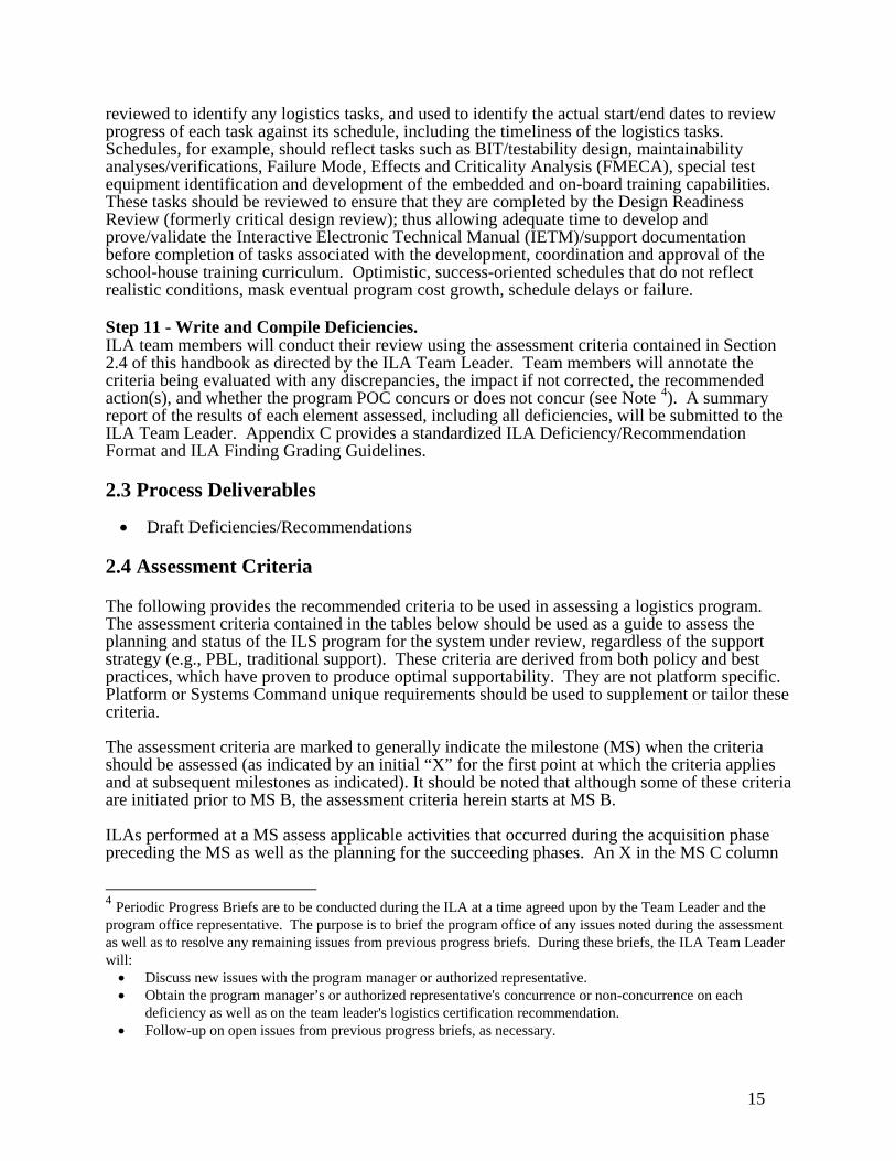
15
reviewed to identify any logistics tasks, and used to identify the actual start/end dates to review progress of each task against its schedule, including the timeliness of the logistics tasks. Schedules, for example, should reflect tasks such as BIT/testability design, maintainability analyses/verifications, Failure Mode, Effects and Criticality Analysis (FMECA), special test equipment identification and development of the embedded and on-board training capabilities. These tasks should be reviewed to ensure that they are completed by the Design Readiness Review (formerly critical design review); thus allowing adequate time to develop and prove/validate the Interactive Electronic Technical Manual (IETM)/support documentation before completion of tasks associated with the development, coordination and approval of the school-house training curriculum. Optimistic, success-oriented schedules that do not reflect realistic conditions, mask eventual program cost growth, schedule delays or failure. Step 11 - Write and Compile Deficiencies. ILA team members will conduct their review using the assessment criteria contained in Section 2.4 of this handbook as directed by the ILA Team Leader. Team members will annotate the criteria being evaluated with any discrepancies, the impact if not corrected, the recommended action(s), and whether the program POC concurs or does not concur (see Note 4). A summary report of the results of each element assessed, including all deficiencies, will be submitted to the ILA Team Leader. Appendix C provides a standardized ILA Deficiency/Recommendation Format and ILA Finding Grading Guidelines. 2.3 Process Deliverables • Draft Deficiencies/Recommendations
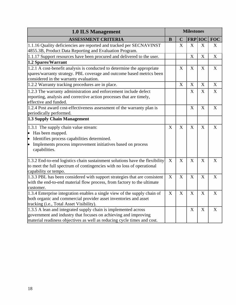
2.4 Assessment Criteria The following provides the recommended criteria to be used in assessing a logistics program. The assessment criteria contained in the tables below should be used as a guide to assess the planning and status of the ILS program for the system under review, regardless of the support strategy (e.g., PBL, traditional support). These criteria are derived from both policy and best practices, which have proven to produce optimal supportability. They are not platform specific. Platform or Systems Command unique requirements should be used to supplement or tailor these criteria. The assessment criteria are marked to generally indicate the milestone (MS) when the criteria should be assessed (as indicated by an initial “X” for the first point at which the criteria applies and at subsequent milestones as indicated). It should be noted that although some of these criteria are initiated prior to MS B, the assessment criteria herein starts at MS B. ILAs performed at a MS assess applicable activities that occurred during the acquisition phase preceding the MS as well as the planning for the succeeding phases. An X in the MS C column
4 Periodic Progress Briefs are to be conducted during the ILA at a time agreed upon by the Team Leader and the program office representative. The purpose is to brief the program office of any issues noted during the assessment as well as to resolve any remaining issues from previous progress briefs. During these briefs, the ILA Team Leader will: • Discuss new issues with the program manager or authorized representative. • Obtain the program manager’s or authorized representative's concurrence or non-concurrence on each
deficiency as well as on the team leader's logistics certification recommendation. • Follow-up on open issues from previous progress briefs, as necessary.

16
does not mean that no logistical support analyses are performed during the preceding phase or prior to MS B. In some cases the criteria assess completion of ILS planning at the milestone, but criteria are also assessed for the planning, schedules and associated funding to accomplish the efforts at a future date: Varying program requirements and acquisition strategies may require further tailoring of the criteria, as they may not always fit all program unique requirements.
17
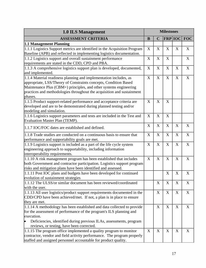
1.0 ILS Management Milestones
ASSESSMENT CRITERIA B C FRP IOC FOC1.1 Management Planning 1.1.1 Logistics Support metrics are identified in the Acquisition Program Baseline (APB) and reflected in implementing logistics documentation.
X X X X X
1.1.2 Logistics support and overall sustainment performance requirements are stated in the CDD, CPD and PBA.
X X X X
1.1.3 A comprehensive logistics support plan is developed, documented, and implemented.
X X X X X
1.1.4 Material readiness planning and implementation includes, as appropriate, LSS/Theory of Constraints concepts, Condition Based Maintenance Plus (CBM+) principles, and other systems engineering practices and methodologies throughout the acquisition and sustainment phases.
X X X X X
1.1.5 Product support-related performance and acceptance criteria are developed and are to be demonstrated during planned testing and/or modeling and simulation.
X X X
1.1.6 Logistics support parameters and tests are included in the Test and Evaluation Master Plan (TEMP).
X X X
1.1.7 IOC/FOC dates are established and defined. X X X X X
1.1.8 Trade studies are conducted on a continuous basis to ensure that performance and supportability goals are met.
X X X X X
1.1.9 Logistics support is included as a part of the life cycle system engineering approach to supportability, including information interoperability requirements.
X X X X X
1.1.10 A risk management program has been established that includes both Government and contractor participation. Logistics support program risks and mitigation plans have been identified and assessed.
X X X X X
1.1.11 Post IOC plans and budgets have been developed for continued evolution of sustainment strategies
X X X
1.1.12 The ULSS/or similar document has been reviewed/coordinated with the user.
X X X X
1.1.13 All user logistics/product support requirements documented in the CDD/CPD have been achieved/met. If not, a plan is in place to ensure they are met.
X X X X
1.1.14 A methodology has been established and data collected to provide for the assessment of performance of the program's ILS planning and execution. • Deficiencies, identified during previous ILAs, assessments, program
reviews, or testing, have been corrected.
X X X X
1.1.15 The program office implemented a quality program to monitor contractor, vendor and field activity performance. The program properly staffed and assigned personnel accountable for product quality.
X X X X X
18
1.0 ILS Management Milestones
ASSESSMENT CRITERIA B C FRP IOC FOC1.1.16 Quality deficiencies are reported and tracked per SECNAVINST 4855.3B, Product Data Reporting and Evaluation Program.
X X X X
1.1.17 Support resources have been procured and delivered to the user. X X X 1.2 Spares/Warrant 1.2.1 A cost-benefit analysis is conducted to determine the appropriate spares/warranty strategy. PBL coverage and outcome based metrics been considered in the warranty evaluation.
X X X X
1.2.2 Warranty tracking procedures are in place. X X X X 1.2.3 The warranty administration and enforcement include defect reporting, analysis and corrective action processes that are timely, effective and funded.
X X X
1.2.4 Post award cost-effectiveness assessment of the warranty plan is periodically performed.
X X X
1.3 Supply Chain Management
1.3.1 The supply chain value stream: • Has been mapped. • Identifies process capabilities determined. • Implements process improvement initiatives based on process
capabilities.
X X X X X
1.3.2 End-to-end logistics chain sustainment solutions have the flexibility to meet the full spectrum of contingencies with no loss of operational capability or tempo.
X X X X X
1.3.3 PBL has been considered with support strategies that are consistent with the end-to-end material flow process, from factory to the ultimate customer.
X X X X X
1.3.4 Enterprise integration enables a single view of the supply chain of both organic and commercial provider asset inventories and asset tracking (i.e., Total Asset Visibility).
X X X X X
1.3.5 A lean and integrated supply chain is implemented across government and industry that focuses on achieving and improving material readiness objectives as well as reducing cycle times and cost.
X X X
19
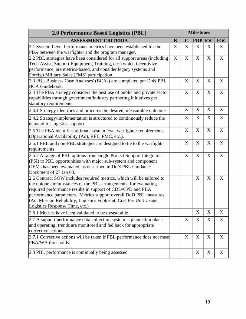
2.0 Performance Based Logistics (PBL) Milestones
ASSESSMENT CRITERIA B C FRP IOC FOC2.1 System Level Performance metrics have been established for the PBA between the warfighter and the program manager.
X X X X X
2.2 PBL strategies have been considered for all support areas (including Tech Assist, Support Equipment, Training, etc.) which incentivize performance, are metrics-based, and consider legacy systems and Foreign Military Sales (FMS) participation.
X X X X X
2.3 PBL Business Case Analyses' (BCAs) are completed per DoN PBL BCA Guidebook.
X X X X
2.4 The PBA strategy considers the best use of public and private sector capabilities through government/industry partnering initiatives per statutory requirements.
X X X X
2.4.1 Strategy identifies and procures the desired, measurable outcome. X X X X
2.4.2 Strategy/implementation is structured to continuously reduce the demand for logistics support.
X X X X
2.5 The PBA identifies ultimate system level warfighter requirements (Operational Availability (Ao), RFT, FMC, etc.).
X X X X
2.5.1 PBL and non-PBL strategies are designed to tie to the warfighter requirements
X X X X
2.5.2 A range of PBL options from single Project Support Integrator (PSI) to PBL opportunities with major sub-system and component OEMs has been evaluated, as described in DoN PBL Guidance Document of 27 Jan 03.
X X X X
2.6 Contract SOW includes required metrics, which will be tailored to the unique circumstances of the PBL arrangements, for evaluating required performance results in support of CDD/CPD and PBA performance parameters. Metrics support overall DoD PBL measures (Ao, Mission Reliability, Logistics Footprint, Cost Per Unit Usage, Logistics Response Time, etc.)
X X X
2.6.1 Metrics have been validated to be measurable. X X X 2.7 A support performance data collection system is planned/in place and operating; trends are monitored and fed back for appropriate corrective actions.
X X X X
2.7.1 Corrective actions will be taken if PBL performance does not meet PBA/WA thresholds.
X X X X
2.8 PBL performance is continually being assessed. X X X
20
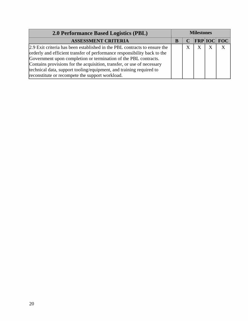
2.0 Performance Based Logistics (PBL) Milestones
ASSESSMENT CRITERIA B C FRP IOC FOC2.9 Exit criteria has been established in the PBL contracts to ensure the orderly and efficient transfer of performance responsibility back to the Government upon completion or termination of the PBL contracts. Contains provisions for the acquisition, transfer, or use of necessary technical data, support tooling/equipment, and training required to reconstitute or recompete the support workload.
X X X X
21
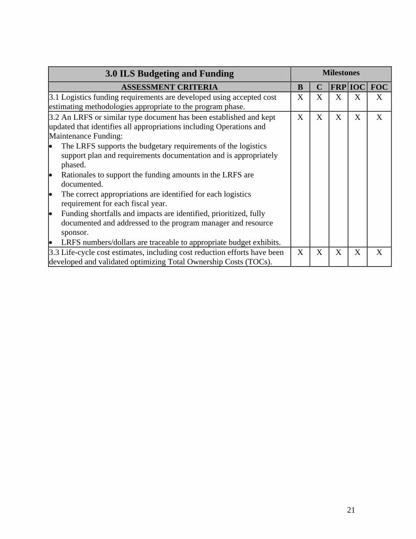
3.0 ILS Budgeting and Funding Milestones
ASSESSMENT CRITERIA B C FRP IOC FOC3.1 Logistics funding requirements are developed using accepted cost estimating methodologies appropriate to the program phase.
X X X X X
3.2 An LRFS or similar type document has been established and kept updated that identifies all appropriations including Operations and Maintenance Funding: • The LRFS supports the budgetary requirements of the logistics
support plan and requirements documentation and is appropriately phased.
• Rationales to support the funding amounts in the LRFS are documented.
• The correct appropriations are identified for each logistics requirement for each fiscal year.
• Funding shortfalls and impacts are identified, prioritized, fully documented and addressed to the program manager and resource sponsor.
• LRFS numbers/dollars are traceable to appropriate budget exhibits.
X
X
X
X
X
3.3 Life-cycle cost estimates, including cost reduction efforts have been developed and validated optimizing Total Ownership Costs (TOCs).
X X X X X

22
This page blank
23
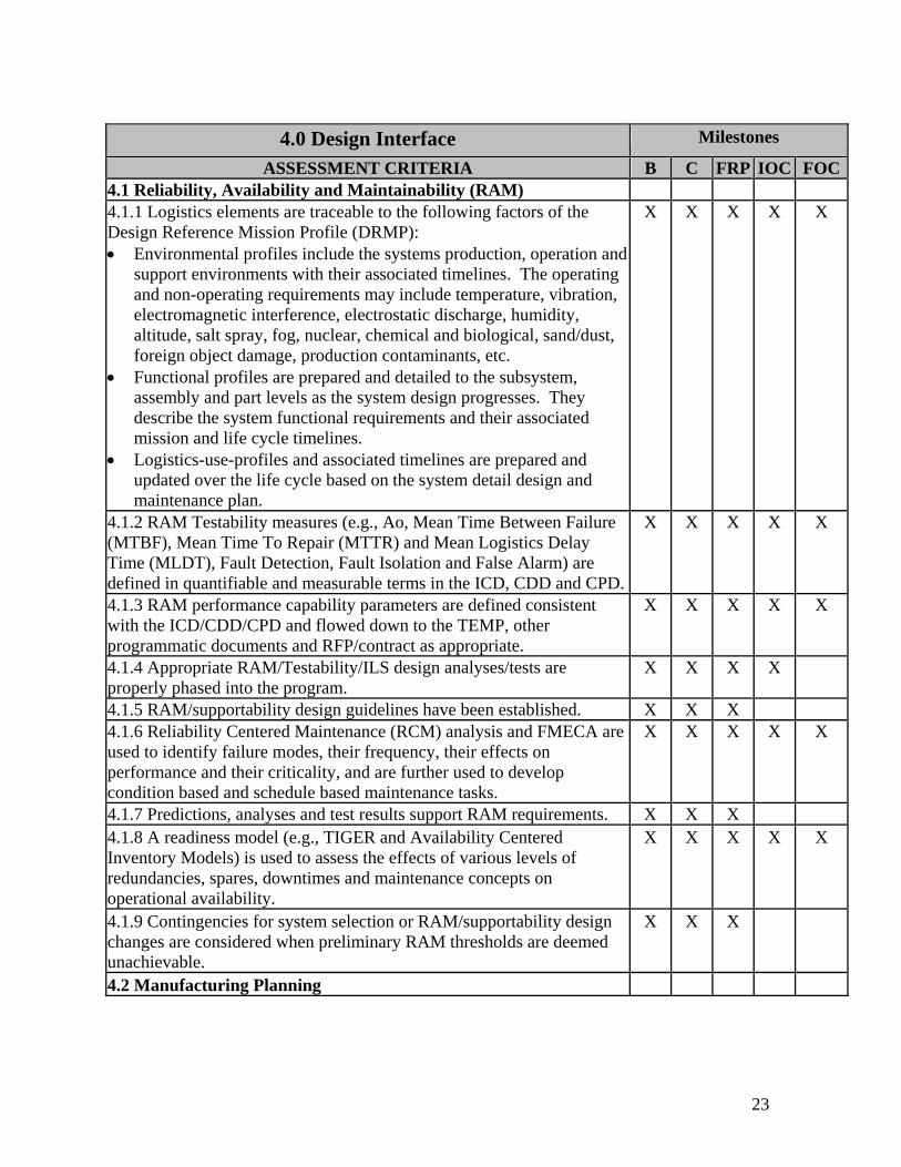
4.0 Design Interface Milestones
ASSESSMENT CRITERIA B C FRP IOC FOC4.1 Reliability, Availability and Maintainability (RAM) 4.1.1 Logistics elements are traceable to the following factors of the Design Reference Mission Profile (DRMP): • Environmental profiles include the systems production, operation and
support environments with their associated timelines. The operating and non-operating requirements may include temperature, vibration, electromagnetic interference, electrostatic discharge, humidity, altitude, salt spray, fog, nuclear, chemical and biological, sand/dust, foreign object damage, production contaminants, etc.
• Functional profiles are prepared and detailed to the subsystem, assembly and part levels as the system design progresses. They describe the system functional requirements and their associated mission and life cycle timelines.
• Logistics-use-profiles and associated timelines are prepared and updated over the life cycle based on the system detail design and maintenance plan.
X X X X X
4.1.2 RAM Testability measures (e.g., Ao, Mean Time Between Failure (MTBF), Mean Time To Repair (MTTR) and Mean Logistics Delay Time (MLDT), Fault Detection, Fault Isolation and False Alarm) are defined in quantifiable and measurable terms in the ICD, CDD and CPD.
X X X X X
4.1.3 RAM performance capability parameters are defined consistent with the ICD/CDD/CPD and flowed down to the TEMP, other programmatic documents and RFP/contract as appropriate.
X X X X X
4.1.4 Appropriate RAM/Testability/ILS design analyses/tests are properly phased into the program.
X X X X
4.1.5 RAM/supportability design guidelines have been established. X X X 4.1.6 Reliability Centered Maintenance (RCM) analysis and FMECA are used to identify failure modes, their frequency, their effects on performance and their criticality, and are further used to develop condition based and schedule based maintenance tasks.
X X X X X
4.1.7 Predictions, analyses and test results support RAM requirements. X X X 4.1.8 A readiness model (e.g., TIGER and Availability Centered Inventory Models) is used to assess the effects of various levels of redundancies, spares, downtimes and maintenance concepts on operational availability.
X X X X X
4.1.9 Contingencies for system selection or RAM/supportability design changes are considered when preliminary RAM thresholds are deemed unachievable.
X X X
4.2 Manufacturing Planning
24
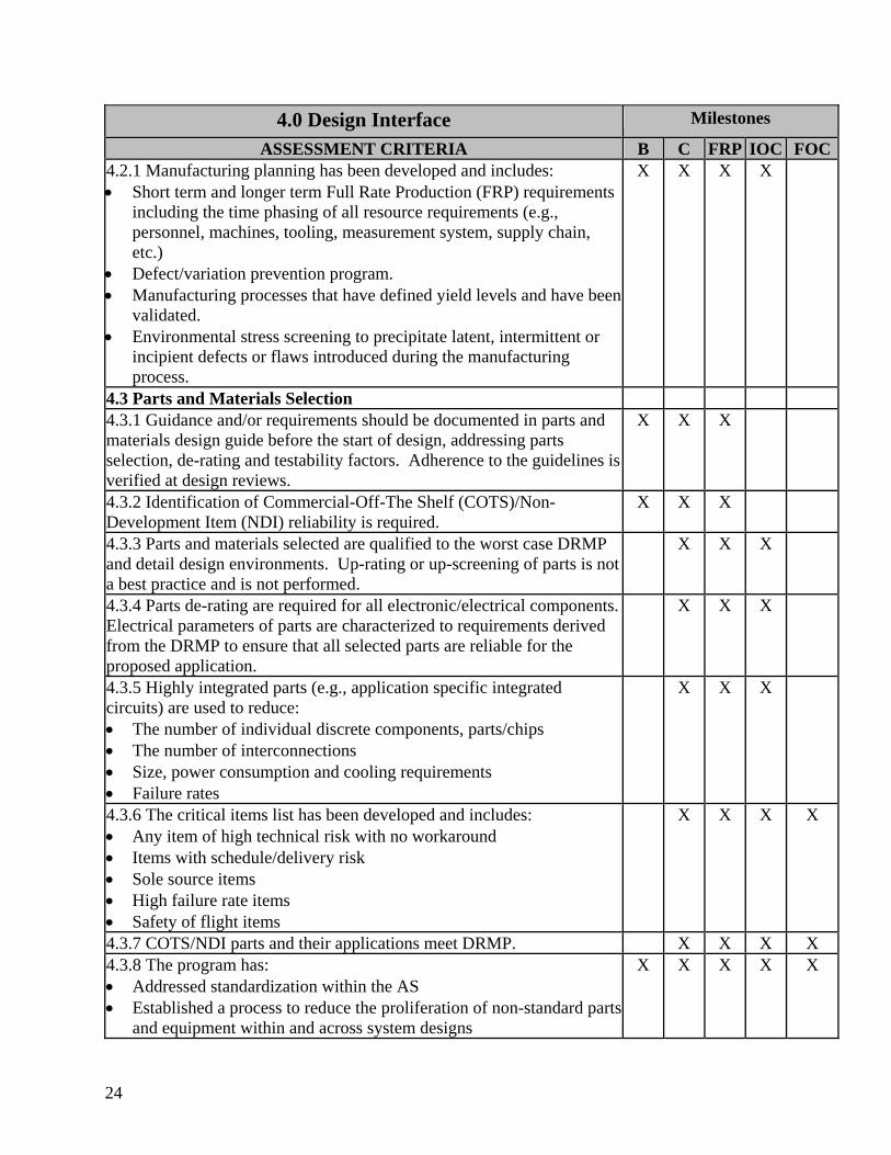
4.0 Design Interface Milestones
ASSESSMENT CRITERIA B C FRP IOC FOC4.2.1 Manufacturing planning has been developed and includes: • Short term and longer term Full Rate Production (FRP) requirements
including the time phasing of all resource requirements (e.g., personnel, machines, tooling, measurement system, supply chain, etc.)
• Defect/variation prevention program. • Manufacturing processes that have defined yield levels and have been
validated. • Environmental stress screening to precipitate latent, intermittent or
incipient defects or flaws introduced during the manufacturing process.
X X X X
4.3 Parts and Materials Selection 4.3.1 Guidance and/or requirements should be documented in parts and materials design guide before the start of design, addressing parts selection, de-rating and testability factors. Adherence to the guidelines isverified at design reviews.
X X X
4.3.2 Identification of Commercial-Off-The Shelf (COTS)/Non-Development Item (NDI) reliability is required.
X X X
4.3.3 Parts and materials selected are qualified to the worst case DRMP and detail design environments. Up-rating or up-screening of parts is not a best practice and is not performed.
X X X
4.3.4 Parts de-rating are required for all electronic/electrical components. Electrical parameters of parts are characterized to requirements derived from the DRMP to ensure that all selected parts are reliable for the proposed application.
X X X
4.3.5 Highly integrated parts (e.g., application specific integrated circuits) are used to reduce: • The number of individual discrete components, parts/chips • The number of interconnections • Size, power consumption and cooling requirements • Failure rates
X X X
4.3.6 The critical items list has been developed and includes: • Any item of high technical risk with no workaround • Items with schedule/delivery risk • Sole source items • High failure rate items • Safety of flight items
X X X X
4.3.7 COTS/NDI parts and their applications meet DRMP. X X X X 4.3.8 The program has: • Addressed standardization within the AS • Established a process to reduce the proliferation of non-standard parts
and equipment within and across system designs
X X X X X
25
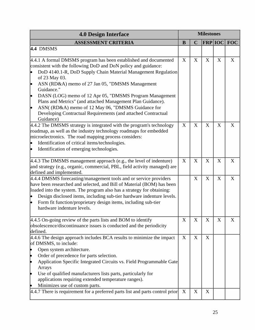
4.0 Design Interface Milestones
ASSESSMENT CRITERIA B C FRP IOC FOC4.4 DMSMS
4.4.1 A formal DMSMS program has been established and documented consistent with the following DoD and DoN policy and guidance: • DoD 4140.1-R, DoD Supply Chain Material Management Regulation
of 23 May 03. • ASN (RD&A) memo of 27 Jan 05, "DMSMS Management
Guidance." • DASN (LOG) memo of 12 Apr 05, "DMSMS Program Management
Plans and Metrics" (and attached Management Plan Guidance). • ASN( (RD&A) memo of 12 May 06, "DMSMS Guidance for
Developing Contractual Requirements (and attached Contractual Guidance)
X X X X X
4.4.2 The DMSMS strategy is integrated with the program's technology roadmap, as well as the industry technology roadmaps for embedded microelectronics. The road mapping process considers: • Identification of critical items/technologies. • Identification of emerging technologies.
X X X X X
4.4.3 The DMSMS management approach (e.g., the level of indenture) and strategy (e.g., organic, commercial, PBL, field activity managed) are defined and implemented.
X X X X X
4.4.4 DMSMS forecasting/management tools and or service providers have been researched and selected, and Bill of Material (BOM) has been loaded into the system. The program also has a strategy for obtaining: • Design disclosed items, including sub-tier hardware indenture levels.• Form fit function/proprietary design items, including sub-tier
hardware indenture levels.
X X X X
4.4.5 On-going review of the parts lists and BOM to identify obsolescence/discontinuance issues is conducted and the periodicity defined.
X X X X X
4.4.6 The design approach includes BCA results to minimize the impact of DMSMS, to include: • Open system architecture. • Order of precedence for parts selection. • Application Specific Integrated Circuits vs. Field Programmable Gate
Arrays • Use of qualified manufacturers lists parts, particularly for
applications requiring extended temperature ranges). • Minimizes use of custom parts.
X X X
4.4.7 There is requirement for a preferred parts list and parts control prior X X X
26
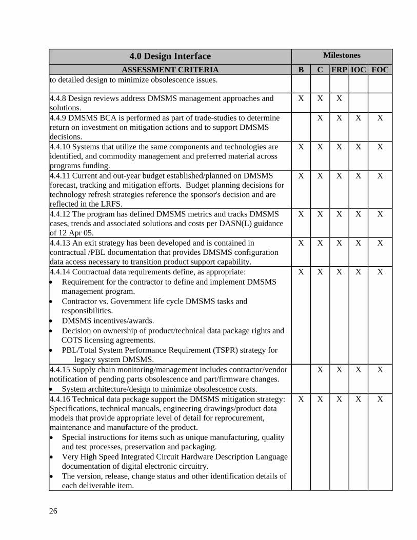
4.0 Design Interface Milestones
ASSESSMENT CRITERIA B C FRP IOC FOCto detailed design to minimize obsolescence issues.
4.4.8 Design reviews address DMSMS management approaches and solutions.
X X X
4.4.9 DMSMS BCA is performed as part of trade-studies to determine return on investment on mitigation actions and to support DMSMS decisions.
X X X X
4.4.10 Systems that utilize the same components and technologies are identified, and commodity management and preferred material across programs funding.
X X X X X
4.4.11 Current and out-year budget established/planned on DMSMS forecast, tracking and mitigation efforts. Budget planning decisions for technology refresh strategies reference the sponsor's decision and are reflected in the LRFS.
X X X X X
4.4.12 The program has defined DMSMS metrics and tracks DMSMS cases, trends and associated solutions and costs per DASN(L) guidance of 12 Apr 05.
X X X X X
4.4.13 An exit strategy has been developed and is contained in contractual /PBL documentation that provides DMSMS configuration data access necessary to transition product support capability.
X X X X X
4.4.14 Contractual data requirements define, as appropriate: • Requirement for the contractor to define and implement DMSMS management program. • Contractor vs. Government life cycle DMSMS tasks and responsibilities. • DMSMS incentives/awards. • Decision on ownership of product/technical data package rights and COTS licensing agreements. • PBL/Total System Performance Requirement (TSPR) strategy for
legacy system DMSMS.
X X X X X
4.4.15 Supply chain monitoring/management includes contractor/vendor notification of pending parts obsolescence and part/firmware changes. • System architecture/design to minimize obsolescence costs.
X X X X
4.4.16 Technical data package support the DMSMS mitigation strategy: Specifications, technical manuals, engineering drawings/product data models that provide appropriate level of detail for reprocurement, maintenance and manufacture of the product. • Special instructions for items such as unique manufacturing, quality
and test processes, preservation and packaging. • Very High Speed Integrated Circuit Hardware Description Language
documentation of digital electronic circuitry. • The version, release, change status and other identification details of
each deliverable item.
X X X X X
27
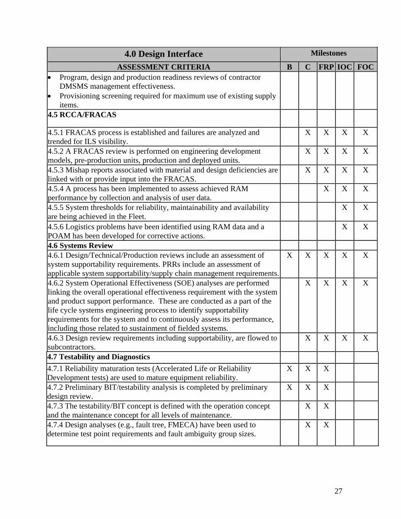
4.0 Design Interface Milestones
ASSESSMENT CRITERIA B C FRP IOC FOC• Program, design and production readiness reviews of contractor
DMSMS management effectiveness. • Provisioning screening required for maximum use of existing supply
items. 4.5 RCCA/FRACAS
4.5.1 FRACAS process is established and failures are analyzed and trended for ILS visibility.
X X X X
4.5.2 A FRACAS review is performed on engineering development models, pre-production units, production and deployed units.
X X X X
4.5.3 Mishap reports associated with material and design deficiencies are linked with or provide input into the FRACAS.
X X X X
4.5.4 A process has been implemented to assess achieved RAM performance by collection and analysis of user data.
X X X
4.5.5 System thresholds for reliability, maintainability and availability are being achieved in the Fleet.
X X
4.5.6 Logistics problems have been identified using RAM data and a POAM has been developed for corrective actions.
X X
4.6 Systems Review 4.6.1 Design/Technical/Production reviews include an assessment of system supportability requirements. PRRs include an assessment of applicable system supportability/supply chain management requirements.
X X X X X
4.6.2 System Operational Effectiveness (SOE) analyses are performed linking the overall operational effectiveness requirement with the system and product support performance. These are conducted as a part of the life cycle systems engineering process to identify supportability requirements for the system and to continuously assess its performance, including those related to sustainment of fielded systems.
X X X X
4.6.3 Design review requirements including supportability, are flowed to subcontractors.
X X X X
4.7 Testability and Diagnostics 4.7.1 Reliability maturation tests (Accelerated Life or Reliability Development tests) are used to mature equipment reliability.
X X X
4.7.2 Preliminary BIT/testability analysis is completed by preliminary design review.
X X X
4.7.3 The testability/BIT concept is defined with the operation concept and the maintenance concept for all levels of maintenance.
X X
4.7.4 Design analyses (e.g., fault tree, FMECA) have been used to determine test point requirements and fault ambiguity group sizes.
X X
28
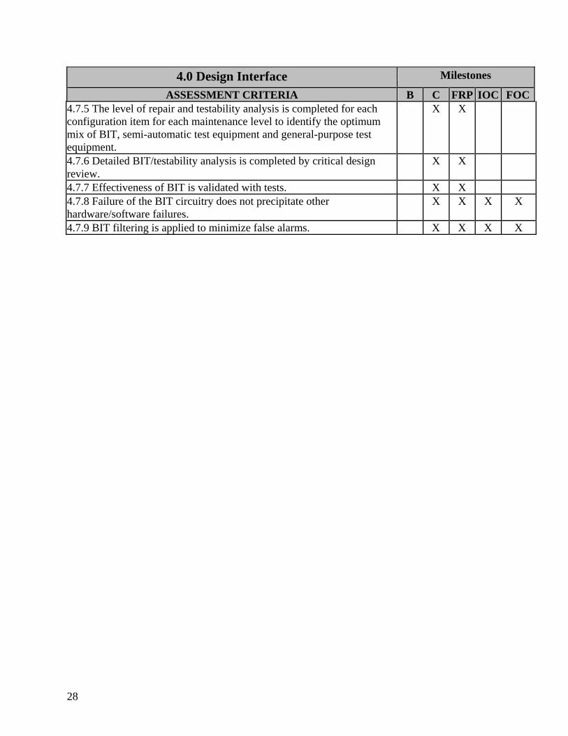
4.0 Design Interface Milestones
ASSESSMENT CRITERIA B C FRP IOC FOC4.7.5 The level of repair and testability analysis is completed for each configuration item for each maintenance level to identify the optimum mix of BIT, semi-automatic test equipment and general-purpose test equipment.
X X
4.7.6 Detailed BIT/testability analysis is completed by critical design review.
X X
4.7.7 Effectiveness of BIT is validated with tests. X X 4.7.8 Failure of the BIT circuitry does not precipitate other hardware/software failures.
X X X X
4.7.9 BIT filtering is applied to minimize false alarms. X X X X
29
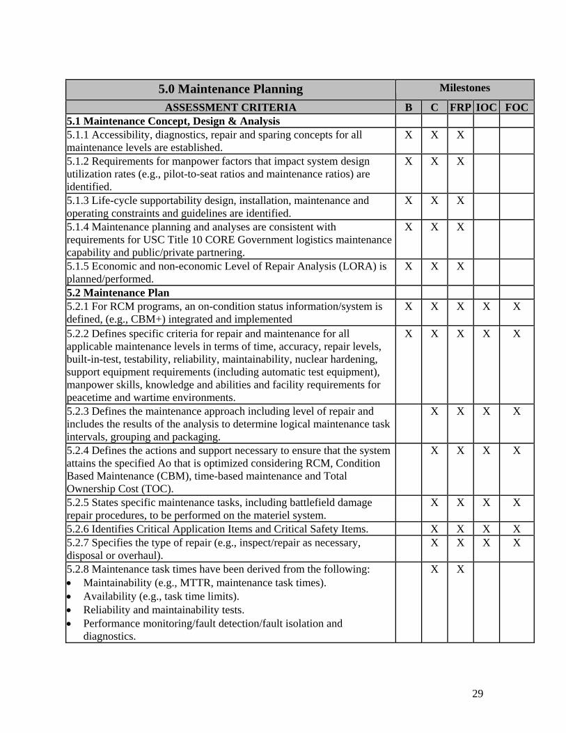
5.0 Maintenance Planning Milestones
ASSESSMENT CRITERIA B C FRP IOC FOC5.1 Maintenance Concept, Design & Analysis 5.1.1 Accessibility, diagnostics, repair and sparing concepts for all maintenance levels are established.
X X X
5.1.2 Requirements for manpower factors that impact system design utilization rates (e.g., pilot-to-seat ratios and maintenance ratios) are identified.
X X X
5.1.3 Life-cycle supportability design, installation, maintenance and operating constraints and guidelines are identified.
X X X
5.1.4 Maintenance planning and analyses are consistent with requirements for USC Title 10 CORE Government logistics maintenance capability and public/private partnering.
X X X
5.1.5 Economic and non-economic Level of Repair Analysis (LORA) is planned/performed.
X X X
5.2 Maintenance Plan 5.2.1 For RCM programs, an on-condition status information/system is defined, (e.g., CBM+) integrated and implemented
X X X X X
5.2.2 Defines specific criteria for repair and maintenance for all applicable maintenance levels in terms of time, accuracy, repair levels, built-in-test, testability, reliability, maintainability, nuclear hardening, support equipment requirements (including automatic test equipment), manpower skills, knowledge and abilities and facility requirements for peacetime and wartime environments.
X X X X X
5.2.3 Defines the maintenance approach including level of repair and includes the results of the analysis to determine logical maintenance task intervals, grouping and packaging.
X X X X
5.2.4 Defines the actions and support necessary to ensure that the system attains the specified Ao that is optimized considering RCM, Condition Based Maintenance (CBM), time-based maintenance and Total Ownership Cost (TOC).
X X X X
5.2.5 States specific maintenance tasks, including battlefield damage repair procedures, to be performed on the materiel system.
X X X X
5.2.6 Identifies Critical Application Items and Critical Safety Items. X X X X 5.2.7 Specifies the type of repair (e.g., inspect/repair as necessary, disposal or overhaul).
X X X X
5.2.8 Maintenance task times have been derived from the following: • Maintainability (e.g., MTTR, maintenance task times). • Availability (e.g., task time limits). • Reliability and maintainability tests. • Performance monitoring/fault detection/fault isolation and
diagnostics.
X X

30
5.0 Maintenance Planning Milestones
ASSESSMENT CRITERIA B C FRP IOC FOC5.2.9 System anomalies and intermittent failures are analyzed for possible changes to the BIT design, thresholds/tolerances and/or filtering.
X X X X
5.2.10 BIT software can be revised independently and without change to the operating software.
X X X X
5.2.11 BIT indications and false alarms are analyzed for corrective action.
X X X X

31
6.0 Support Equipment Milestones
ASSESSMENT CRITERIA B C FRP IOC FOC6.1 The environmental and physical constraints, such as size, weight, power, temperatures and interfaces have been factored into Support Equipment (SE) design.
X X X
6.2 Analyses to identify the optimum mix of automatic and manual fault detection and isolation equipment at each applicable maintenance level has been conducted.
X X X
6.3 Types and quantity of SE for each location have been established. X X X X 6.4 The SE manpower, training, maintenance levels and maintenance task requirements are identified.
X X X X
6.5 The SE requirements document (or equivalent) is submitted by the contractor to justify SE requirements and initiate follow-on support activities.
X X
6.6 Required technical documentation to support the SE is identified and includes: • Procedures to perform the required tests and diagnostics. • Test measurement and diagnostic equipment calibration requirements
and associated technical parameters. • All product/technical data required to support and operate required
support equipment throughout the life cycle of that product. • Test fixtures and/or interfaces to connect the system to the test
equipment.
X X X X
6.7 Provisioning documentation identifies: • Tools and test equipment by task function and maintenance level;
Category codes (e.g., source, maintenance and recoverability codes) are identified for SE;
• Manufacturer's part numbers, nomenclatures, descriptions, estimated prices and recommended SE qualities.
X X X X
6.8 Test Program Sets (TPS) and associated documentation have been evaluated and verified.
X X X X
6.9 The TPSs used at maintenance sites will be available at IOC/FOC. X X X X 6.10 Verified TPSs have been duplicated and will be delivered to operational sites in time for IOC/FOC.
X X X X
6.11 Availability of support equipment and tools at required maintenance sites and training schools have been verified.
X X
6.12 SE has been identified in the Coordinated Shipboard Allowance List (COSAL)/Navy Tactical Command Support System database.
X X X

32
This page blank

33
7.0 Supply Support Milestones
ASSESSMENT CRITERIA B C FRP IOC FOC7.1 Sparing Analysis 7.1.1 Sparing analyses and levels • Are based on use of an DoN approved Readiness Based Spares (RBS)
methodology (i.e., models in the Navy RBS Workstation such as ARROWS, ACIM/TIGER and CARES) when appropriate
• Are performed in the multi-echelon and multi-indenture model based on the applicable maintenance plan for DoN owned material at all echelons of supply.
• Demand based DoN approved models (such as Fleet Logistics Support Improvement Program or Retail Inventory Management for Aviation) are used when data is inadequate or the RBS approach is not cost effective and OPNAV (N412) has approved a waiver.
X X X X X
7.1.2 Supply chain metrics tracking and management processes are developed and implemented to assess performance against requirements for corrective actions.
X X X X X
7.1.3 RBS results are presented at MS Reviews. X X X 7.1.4 If PBL contractor will be responsible for response time and fill rate metrics, but Navy will own material at the consumer level, RBS is used to determine the consumer level based on the operational scenario of the platform. Definition of success is determined by meeting contracted SCM metrics.
X X X X X
7.2 Asset Management Planning 7.2.1 The inventory of spares to be procured is determined and spares records are maintained.
X X X X
7.2.2 Allowances are determined. X X X X 7.2.3 Provisions for surge requirements are identified and included in the PBL contract(s).
X X X X
7.2.4 Provisioning conferences are conducted, as necessary, to determine if the contractor’s provisioning preparation, documentation and facilities are adequate.
X X X X
7.2.5 Provisioning screening has been conducted to: • Prevent duplicate entries in the DoD supply data system. • Obtain most cost-effective support, including consideration of using
existing supply items.
X X X X
7.2.6 Item management codes are assigned, which include source, maintenance and recoverability codes.
X X X X
7.2.7 Provisioning data reports, such as the following examples have been generated: • Recommended repair parts list provided for preoperational repair
parts and training equipment. • Provisioning parts list determining the range and quantity of support
X X X X
34
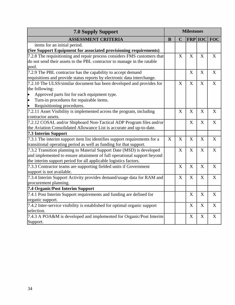
7.0 Supply Support Milestones
ASSESSMENT CRITERIA B C FRP IOC FOCitems for an initial period.
(See Support Equipment for associated provisioning requirements) 7.2.8 The requisitioning and repair process considers FMS customers that do not send their assets to the PBL contractor to manage in the ratable pool.
X X X X
7.2.9 The PBL contractor has the capability to accept demand requisitions and provide status reports by electronic data interchange.
X X X
7.2.10 The ULSS/similar document has been developed and provides for the following: • Approved parts list for each equipment type. • Turn-in procedures for repairable items. • Requisitioning procedures.
X X X X
7.2.11 Asset Visibility is implemented across the program, including contractor assets.
X X X X
7.2.12 COSAL and/or Shipboard Non-Tactical ADP Program files and/or the Aviation Consolidated Allowance List is accurate and up-to-date.
X X X
7.3 Interim Support 7.3.1 The interim support item list identifies support requirements for a transitional operating period as well as funding for that support.
X X X X X
7.3.2 Transition planning to Material Support Date (MSD) is developed and implemented to ensure attainment of full operational support beyond the interim support period for all applicable logistics factors.
X X X X
7.3.3 Contractor teams are supporting fielded units if Government support is not available.
X X X X
7.3.4 Interim Support Activity provides demand/usage data for RAM and procurement planning.
X X X X
7.4 Organic/Post Interim Support 7.4.1 Post Interim Support requirements and funding are defined for organic support.
X X X
7.4.2 Inter-service visibility is established for optimal organic support selection.
X X X
7.4.3 A POA&M is developed and implemented for Organic/Post Interim Support.
X X X
35
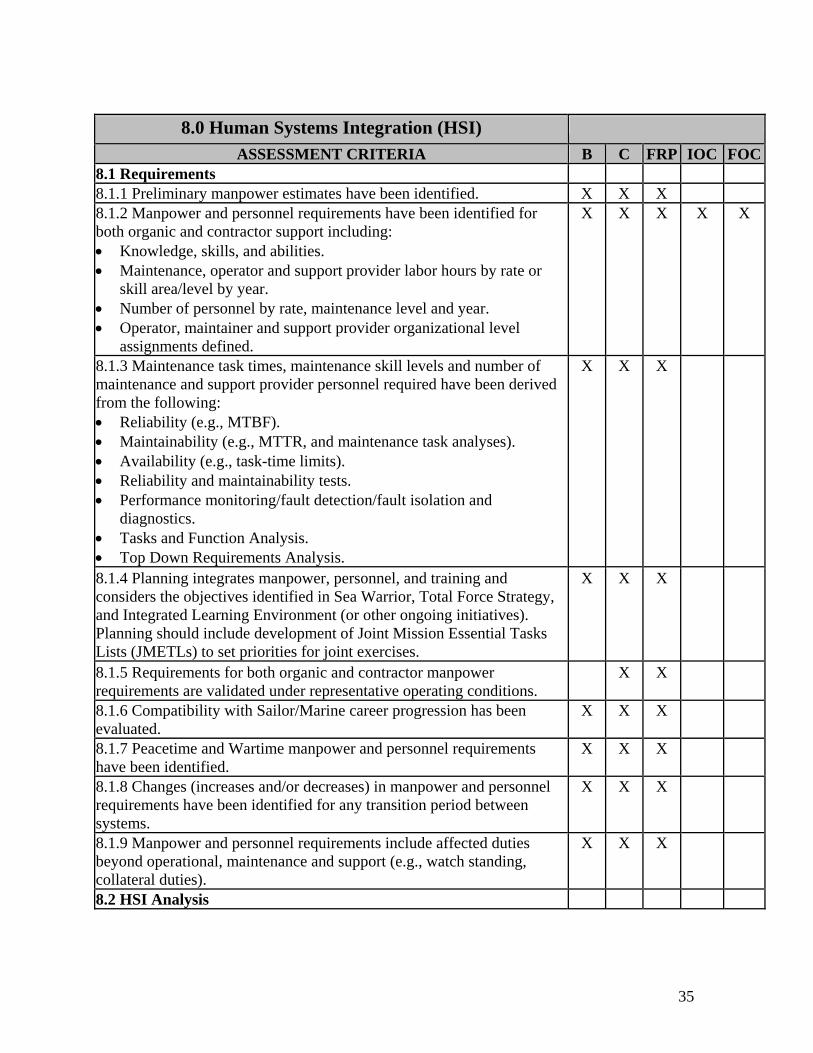
8.0 Human Systems Integration (HSI)
ASSESSMENT CRITERIA B C FRP IOC FOC8.1 Requirements 8.1.1 Preliminary manpower estimates have been identified. X X X 8.1.2 Manpower and personnel requirements have been identified for both organic and contractor support including: • Knowledge, skills, and abilities. • Maintenance, operator and support provider labor hours by rate or
skill area/level by year. • Number of personnel by rate, maintenance level and year. • Operator, maintainer and support provider organizational level
assignments defined.
X X X X X
8.1.3 Maintenance task times, maintenance skill levels and number of maintenance and support provider personnel required have been derived from the following: • Reliability (e.g., MTBF). • Maintainability (e.g., MTTR, and maintenance task analyses). • Availability (e.g., task-time limits). • Reliability and maintainability tests. • Performance monitoring/fault detection/fault isolation and
diagnostics. • Tasks and Function Analysis. • Top Down Requirements Analysis.
X X X
8.1.4 Planning integrates manpower, personnel, and training and considers the objectives identified in Sea Warrior, Total Force Strategy, and Integrated Learning Environment (or other ongoing initiatives). Planning should include development of Joint Mission Essential Tasks Lists (JMETLs) to set priorities for joint exercises.
X X X
8.1.5 Requirements for both organic and contractor manpower requirements are validated under representative operating conditions.
X X
8.1.6 Compatibility with Sailor/Marine career progression has been evaluated.
X X X
8.1.7 Peacetime and Wartime manpower and personnel requirements have been identified.
X X X
8.1.8 Changes (increases and/or decreases) in manpower and personnel requirements have been identified for any transition period between systems.
X X X
8.1.9 Manpower and personnel requirements include affected duties beyond operational, maintenance and support (e.g., watch standing, collateral duties).
X X X
8.2 HSI Analysis

36
8.0 Human Systems Integration (HSI)
ASSESSMENT CRITERIA B C FRP IOC FOC8.2.1 HFE analysis has been performed addressing operator and maintainer: • Accessibility • Visibility • Human factors/ergonomics • Testability • Complexity • Standardization and interchangeability • Use of mock-ups, modeling and simulation • Operational experience • Workspace Environment - heating, cooling, ventilation, illumination,
noise, vibration • Design for effective handling and carrying • Controls and displays • User computer interface • Safety and survivability
X X X
8.2.2 Broad cognitive, physical and sensory requirements for the operators, maintainers and support personnel that contribute/constrain to total system performance have been analyzed.
X X X
8.2.3 An HSI plan has been developed, resourced, executed and maintained, and has been coordinated with subsystem HSI plans and the overall Systems Engineering Plan.
X X X
8.3 Training System Planning (TSP) 8.3.1 A Training Planning Process Methodology (TRPPM) is conducted. X X X 8.3.2 Resource requirements are specified for training equipment, services, materials, facilities, and personnel.
X X X X X
8.3.3 Instruction in formal schools, on-the-job-training and follow-on training includes: • System operation and maintenance levels (e.g., daily, weekly,
monthly, quarterly, semi-annually, and on condition). • Individual and team training. • Instructor training.
X X X X X
8.3.4 Training requirements reflect configuration updates to the weapon system.
X X X X X
8.3.5 The TSP is approved. • A preliminary TSP is required by MS B.
X X
8.4 Training Outline and Curricula Design 8.4.1 Terminal training objectives are defined in detail. X X 8.4.2 Specific criteria are established to determine the success of training. X X X 8.4.3 Operator and maintainer training are embedded in the IETM. Job performance aids are included.
X X X X X
37
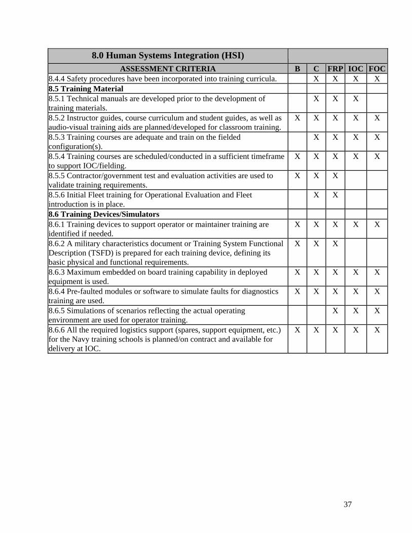
8.0 Human Systems Integration (HSI)
ASSESSMENT CRITERIA B C FRP IOC FOC8.4.4 Safety procedures have been incorporated into training curricula. X X X X 8.5 Training Material 8.5.1 Technical manuals are developed prior to the development of training materials.
X X X
8.5.2 Instructor guides, course curriculum and student guides, as well as audio-visual training aids are planned/developed for classroom training.
X X X X X
8.5.3 Training courses are adequate and train on the fielded configuration(s).
X X X X
8.5.4 Training courses are scheduled/conducted in a sufficient timeframe to support IOC/fielding.
X X X X X
8.5.5 Contractor/government test and evaluation activities are used to validate training requirements.
X X X
8.5.6 Initial Fleet training for Operational Evaluation and Fleet introduction is in place.
X X
8.6 Training Devices/Simulators 8.6.1 Training devices to support operator or maintainer training are identified if needed.
X X X X X
8.6.2 A military characteristics document or Training System Functional Description (TSFD) is prepared for each training device, defining its basic physical and functional requirements.
X X X
8.6.3 Maximum embedded on board training capability in deployed equipment is used.
X X X X X
8.6.4 Pre-faulted modules or software to simulate faults for diagnostics training are used.
X X X X X
8.6.5 Simulations of scenarios reflecting the actual operating environment are used for operator training.
X X X
8.6.6 All the required logistics support (spares, support equipment, etc.) for the Navy training schools is planned/on contract and available for delivery at IOC.
X X X X X

38
This page blank

39
9.0 Packaging, Handling, Storage and Transportation
(PHS&T)
ASSESSMENT CRITERIA B C FRP IOC FOC9.1 Requirements 9.1.1 Storage, handling and transportation profiles of the configuration items over the system life cycle from acceptance through disposal have been derived from the DRMP.
X X X
9.1.2 A PHS&T Plan has been developed that identifies the program strategy for safely packaging, handling, storing, and transporting the system as well as any special requirements and interfaces with agencies or DoD components responsible for transporting the system.
X X X X X
9.1.3 DoD's computerized Container Design Retrieval System database has been searched to preclude the design of new specialized containers when suitable one exists in the system.
X X X
9.1.4 Military Packaging, MIL-STD-2073 is used for: • Items that cannot be protected and preserved in a cost-effective
manner using commercial packaging. • Items delivered during wartime for deployment with operational
units. • Items requiring reusable containers. • Items intended for delivery-at-sea. • An item where the contractor has determined military packaging is
the optimal packaging solution.
X X X X X
9.1.5 Packaging intended for international use has been approved by the Department of Transportation.
X X X X
9.1.6 Storage monitoring requirements are incorporated into technical publications.
X X X X X
9.1.7 Transportability problems are addressed, to include: • Oversized/overweight items. • Items requiring special transportation modes. • Items that are classified.
X X X X X
9.1.8 Transportation requirements with Federal and State agencies have been identified (such as height, weight, etc.) and any necessary waivers obtained for highway or rail transport.
X X X X X
9.1.9 Rail, air and ship certifications have been obtained or are scheduled/coordinated with the appropriate platform manager or agency. This includes tie down patterns, rail impact tests, load modeling or load demonstration, and interfaces between the system being transported and the transporting platform.
X X X X X
9.1.10 Shelf-life requirements have been identified. X X X X X 9.1.11Time delivery requirements for all shipments to the Navy from contractors have been identified.
X X X X
40
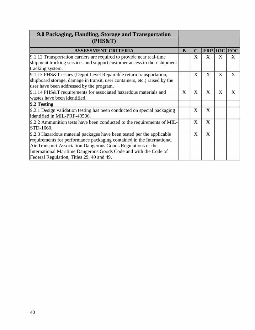
9.0 Packaging, Handling, Storage and Transportation (PHS&T)
ASSESSMENT CRITERIA B C FRP IOC FOC9.1.12 Transportation carriers are required to provide near real-time shipment tracking services and support customer access to their shipment tracking system.
X X X X
9.1.13 PHS&T issues (Depot Level Repairable return transportation, shipboard storage, damage in transit, user containers, etc.) raised by the user have been addressed by the program.
X X X X
9.1.14 PHS&T requirements for associated hazardous materials and wastes have been identified.
X X X X X
9.2 Testing 9.2.1 Design validation testing has been conducted on special packaging identified in MIL-PRF-49506.
X X
9.2.2 Ammunition tests have been conducted to the requirements of MIL-STD-1660.
X X
9.2.3 Hazardous material packages have been tested per the applicable requirements for performance packaging contained in the International Air Transport Association Dangerous Goods Regulations or the International Maritime Dangerous Goods Code and with the Code of Federal Regulation, Titles 29, 40 and 49.
X X
41
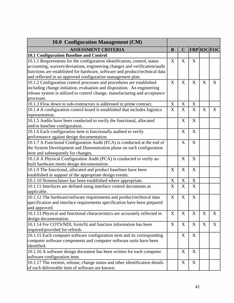
10.0 Configuration Management (CM)
ASSESSMENT CRITERIA B C FRP IOC FOC10.1 Configuration Baseline and Control 10.1.1 Requirements for the configuration identification, control, status accounting, waivers/deviations, engineering changes and verification/audit functions are established for hardware, software and product/technical data and reflected in an approved configuration management plan.
X X X
10.1.2 Configuration control processes and procedures are established including change initiation, evaluation and disposition. An engineering release system is utilized to control change, manufacturing and acceptance processes.
X X X X X
10.1.3 Flow down to sub-contractors is addressed in prime contract. X X X 10.1.4 A configuration control board is established that includes logistics representation.
X X X X X
10.1.5 Audits have been conducted to verify the functional, allocated and/or baseline configuration.
X X
10.1.6 Each configuration item is functionally audited to verify performance against design documentation.
X X
10.1.7 A Functional Configuration Audit (FCA) is conducted at the end of the System Development and Demonstration phase on each configuration item and subsequently for changes.
X X
10.1.8 A Physical Configuration Audit (PCA) is conducted to verify as-built hardware meets design documentation.
X X
10.1.9 The functional, allocated and product baselines have been established in support of the appropriate design events.
X X X
10.1.10 Nomenclature has been established where appropriate. X X X 10.1.11 Interfaces are defined using interface control documents as applicable.
X X X
10.1.12 The hardware/software requirements and product/technical data specification and interface requirements specification have been prepared and approved.
X X X
10.1.13 Physical and functional characteristics are accurately reflected in design documentation.
X X X X X
10.1.14 For COTS/NDI, form/fit and function information has been required/provided for refresh.
X X X X X
10.1.15 Each computer software configuration item and its corresponding computer software components and computer software units have been identified.
X X
10.1.16 A software design document has been written for each computer software configuration item.
X X
10.1.17 The version, release, change status and other identification details of each deliverable item of software are known.
X X
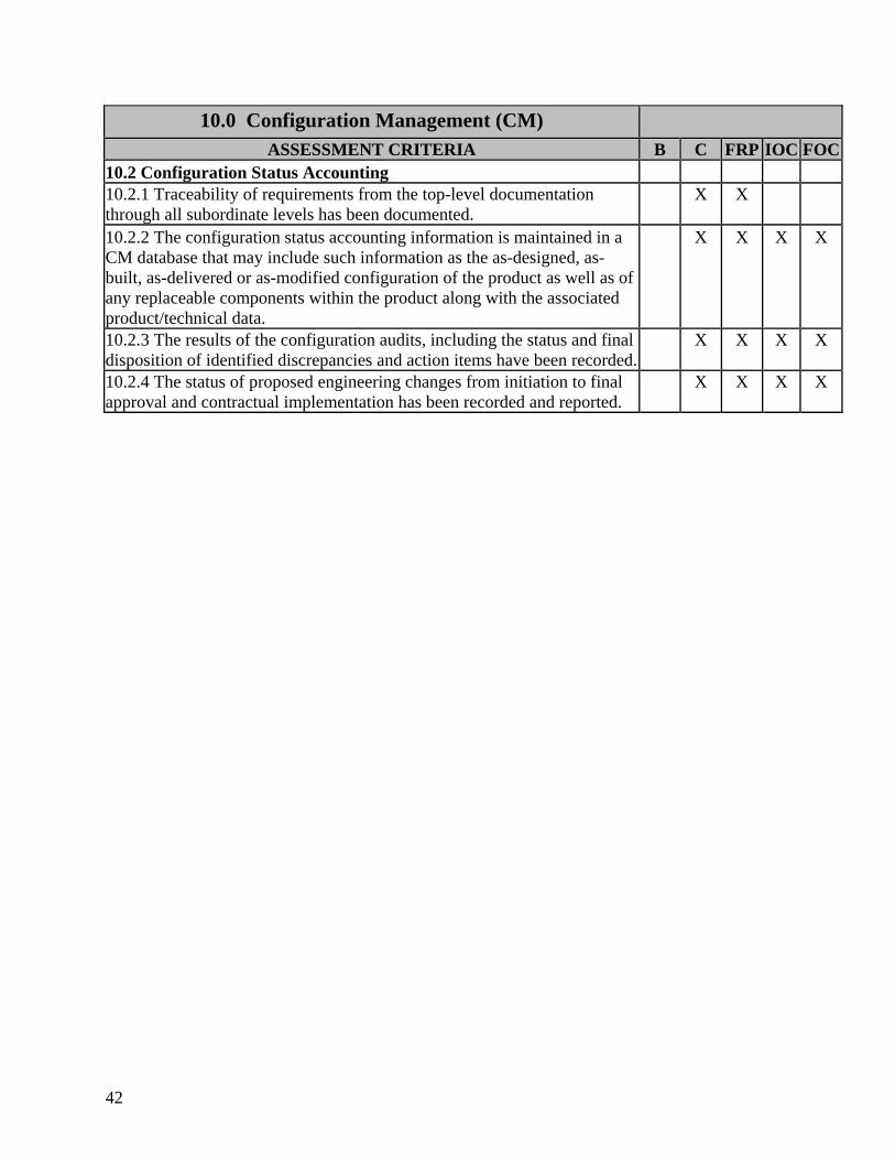
42
10.0 Configuration Management (CM)
ASSESSMENT CRITERIA B C FRP IOC FOC10.2 Configuration Status Accounting 10.2.1 Traceability of requirements from the top-level documentation through all subordinate levels has been documented.
X X
10.2.2 The configuration status accounting information is maintained in a CM database that may include such information as the as-designed, as-built, as-delivered or as-modified configuration of the product as well as of any replaceable components within the product along with the associated product/technical data.
X X X X
10.2.3 The results of the configuration audits, including the status and final disposition of identified discrepancies and action items have been recorded.
X X X X
10.2.4 The status of proposed engineering changes from initiation to final approval and contractual implementation has been recorded and reported.
X X X X
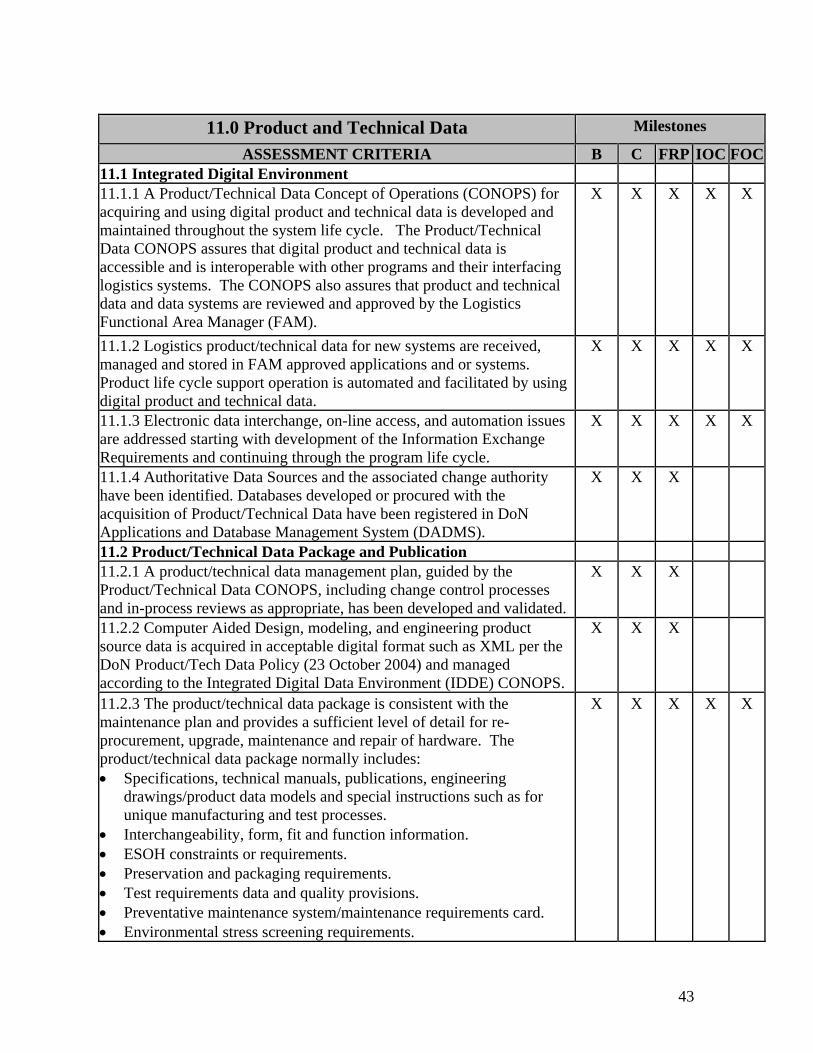
43
11.0 Product and Technical Data Milestones
ASSESSMENT CRITERIA B C FRP IOC FOC11.1 Integrated Digital Environment 11.1.1 A Product/Technical Data Concept of Operations (CONOPS) for acquiring and using digital product and technical data is developed and maintained throughout the system life cycle. The Product/Technical Data CONOPS assures that digital product and technical data is accessible and is interoperable with other programs and their interfacing logistics systems. The CONOPS also assures that product and technical data and data systems are reviewed and approved by the Logistics Functional Area Manager (FAM).
X X X X X
11.1.2 Logistics product/technical data for new systems are received, managed and stored in FAM approved applications and or systems. Product life cycle support operation is automated and facilitated by using digital product and technical data.
X X X X X
11.1.3 Electronic data interchange, on-line access, and automation issues are addressed starting with development of the Information Exchange Requirements and continuing through the program life cycle.
X X X X X
11.1.4 Authoritative Data Sources and the associated change authority have been identified. Databases developed or procured with the acquisition of Product/Technical Data have been registered in DoN Applications and Database Management System (DADMS).
X X X
11.2 Product/Technical Data Package and Publication 11.2.1 A product/technical data management plan, guided by the Product/Technical Data CONOPS, including change control processes and in-process reviews as appropriate, has been developed and validated.
X X X
11.2.2 Computer Aided Design, modeling, and engineering product source data is acquired in acceptable digital format such as XML per the DoN Product/Tech Data Policy (23 October 2004) and managed according to the Integrated Digital Data Environment (IDDE) CONOPS.
X X X
11.2.3 The product/technical data package is consistent with the maintenance plan and provides a sufficient level of detail for re-procurement, upgrade, maintenance and repair of hardware. The product/technical data package normally includes: • Specifications, technical manuals, publications, engineering
drawings/product data models and special instructions such as for unique manufacturing and test processes.
• Interchangeability, form, fit and function information. • ESOH constraints or requirements. • Preservation and packaging requirements. • Test requirements data and quality provisions. • Preventative maintenance system/maintenance requirements card. • Environmental stress screening requirements.
X X X X X
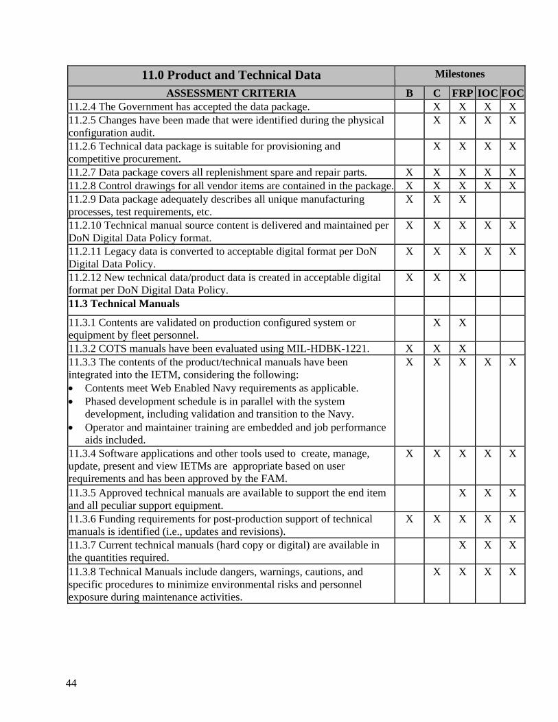
44
11.0 Product and Technical Data Milestones
ASSESSMENT CRITERIA B C FRP IOC FOC11.2.4 The Government has accepted the data package. X X X X 11.2.5 Changes have been made that were identified during the physical configuration audit.
X X X X
11.2.6 Technical data package is suitable for provisioning and competitive procurement.
X X X X
11.2.7 Data package covers all replenishment spare and repair parts. X X X X X 11.2.8 Control drawings for all vendor items are contained in the package. X X X X X 11.2.9 Data package adequately describes all unique manufacturing processes, test requirements, etc.
X X X
11.2.10 Technical manual source content is delivered and maintained per DoN Digital Data Policy format.
X X X X X
11.2.11 Legacy data is converted to acceptable digital format per DoN Digital Data Policy.
X X X X X
11.2.12 New technical data/product data is created in acceptable digital format per DoN Digital Data Policy.
X X X
11.3 Technical Manuals
11.3.1 Contents are validated on production configured system or equipment by fleet personnel.
X X
11.3.2 COTS manuals have been evaluated using MIL-HDBK-1221. X X X 11.3.3 The contents of the product/technical manuals have been integrated into the IETM, considering the following: • Contents meet Web Enabled Navy requirements as applicable. • Phased development schedule is in parallel with the system
development, including validation and transition to the Navy. • Operator and maintainer training are embedded and job performance
aids included.
X X X X X
11.3.4 Software applications and other tools used to create, manage, update, present and view IETMs are appropriate based on user requirements and has been approved by the FAM.
X X X X X
11.3.5 Approved technical manuals are available to support the end item and all peculiar support equipment.
X X X
11.3.6 Funding requirements for post-production support of technical manuals is identified (i.e., updates and revisions).
X X X X X
11.3.7 Current technical manuals (hard copy or digital) are available in the quantities required.
X X X
11.3.8 Technical Manuals include dangers, warnings, cautions, and specific procedures to minimize environmental risks and personnel exposure during maintenance activities.
X X X X
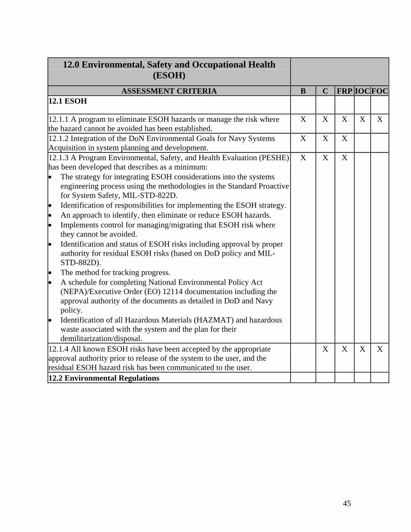
45
12.0 Environmental, Safety and Occupational Health
(ESOH)
ASSESSMENT CRITERIA B C FRP IOC FOC12.1 ESOH
12.1.1 A program to eliminate ESOH hazards or manage the risk where the hazard cannot be avoided has been established.
X X X X X
12.1.2 Integration of the DoN Environmental Goals for Navy Systems Acquisition in system planning and development.
X X X
12.1.3 A Program Environmental, Safety, and Health Evaluation (PESHE) has been developed that describes as a minimum: • The strategy for integrating ESOH considerations into the systems
engineering process using the methodologies in the Standard Proactive for System Safety, MIL-STD-822D.
• Identification of responsibilities for implementing the ESOH strategy. • An approach to identify, then eliminate or reduce ESOH hazards. • Implements control for managing/migrating that ESOH risk where
they cannot be avoided. • Identification and status of ESOH risks including approval by proper
authority for residual ESOH risks (based on DoD policy and MIL-STD-882D).
• The method for tracking progress. • A schedule for completing National Environmental Policy Act
(NEPA)/Executive Order (EO) 12114 documentation including the approval authority of the documents as detailed in DoD and Navy policy.
• Identification of all Hazardous Materials (HAZMAT) and hazardous waste associated with the system and the plan for their demilitarization/disposal.
X X X
12.1.4 All known ESOH risks have been accepted by the appropriate approval authority prior to release of the system to the user, and the residual ESOH hazard risk has been communicated to the user.
X X X X
12.2 Environmental Regulations
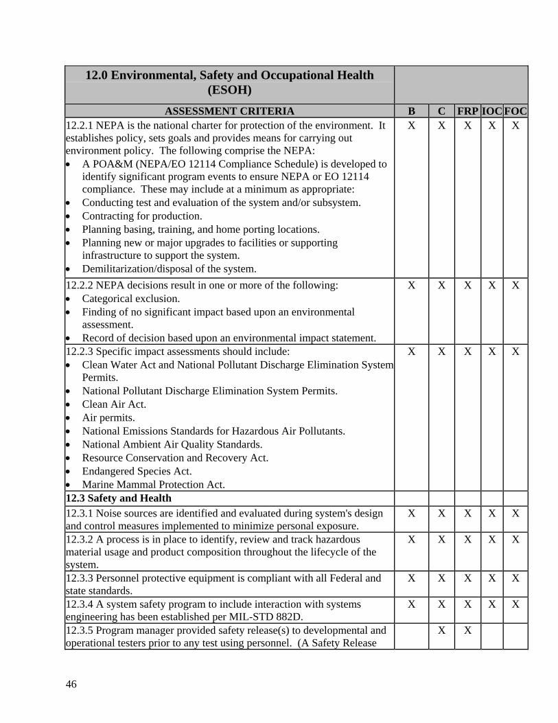
46
12.0 Environmental, Safety and Occupational Health (ESOH)
ASSESSMENT CRITERIA B C FRP IOC FOC12.2.1 NEPA is the national charter for protection of the environment. It establishes policy, sets goals and provides means for carrying out environment policy. The following comprise the NEPA: • A POA&M (NEPA/EO 12114 Compliance Schedule) is developed to
identify significant program events to ensure NEPA or EO 12114 compliance. These may include at a minimum as appropriate:
• Conducting test and evaluation of the system and/or subsystem. • Contracting for production. • Planning basing, training, and home porting locations. • Planning new or major upgrades to facilities or supporting
infrastructure to support the system. • Demilitarization/disposal of the system.
X X X X X
12.2.2 NEPA decisions result in one or more of the following: • Categorical exclusion. • Finding of no significant impact based upon an environmental
assessment. • Record of decision based upon an environmental impact statement.
X X X X X
12.2.3 Specific impact assessments should include: • Clean Water Act and National Pollutant Discharge Elimination System
Permits. • National Pollutant Discharge Elimination System Permits. • Clean Air Act. • Air permits. • National Emissions Standards for Hazardous Air Pollutants. • National Ambient Air Quality Standards. • Resource Conservation and Recovery Act. • Endangered Species Act. • Marine Mammal Protection Act.
X X X X X
12.3 Safety and Health 12.3.1 Noise sources are identified and evaluated during system's design and control measures implemented to minimize personal exposure.
X X X X X
12.3.2 A process is in place to identify, review and track hazardous material usage and product composition throughout the lifecycle of the system.
X X X X X
12.3.3 Personnel protective equipment is compliant with all Federal and state standards.
X X X X X
12.3.4 A system safety program to include interaction with systems engineering has been established per MIL-STD 882D.
X X X X X
12.3.5 Program manager provided safety release(s) to developmental and operational testers prior to any test using personnel. (A Safety Release
X X
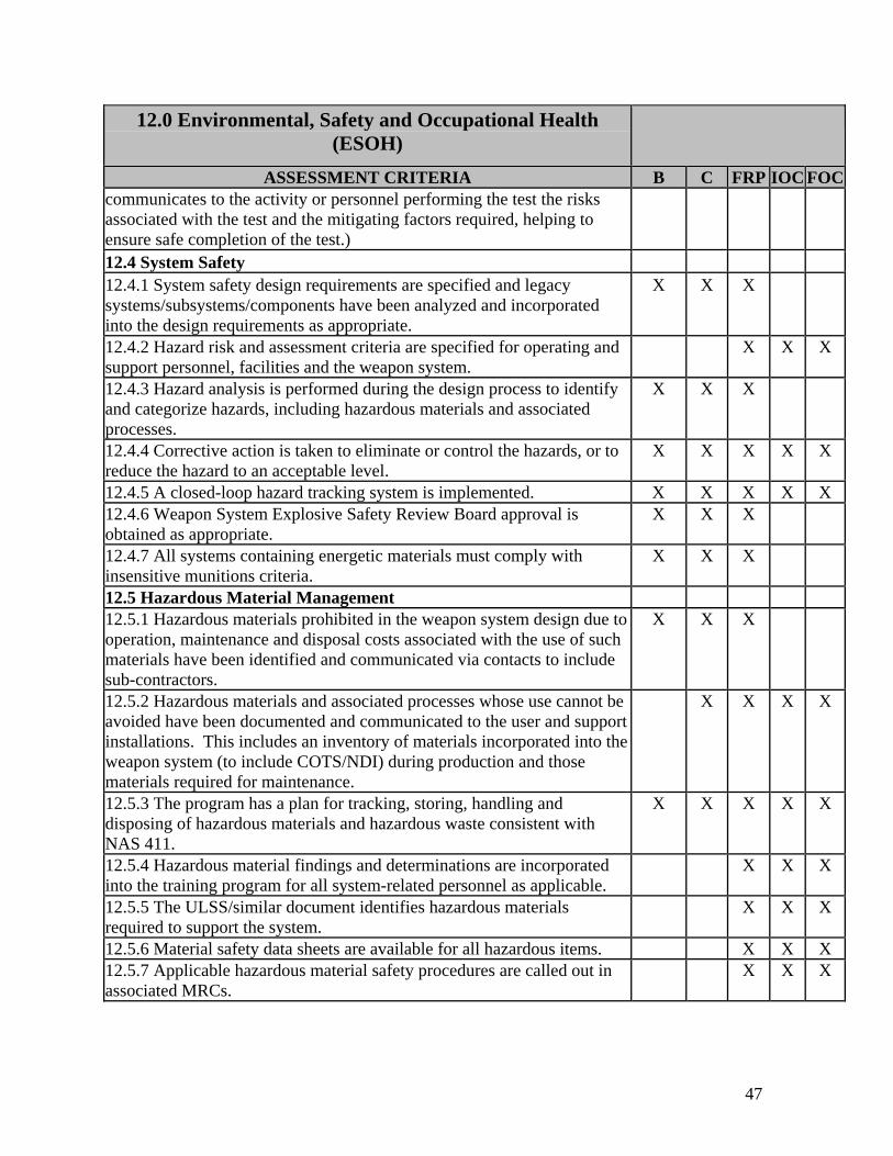
47
12.0 Environmental, Safety and Occupational Health (ESOH)
ASSESSMENT CRITERIA B C FRP IOC FOCcommunicates to the activity or personnel performing the test the risks associated with the test and the mitigating factors required, helping to ensure safe completion of the test.) 12.4 System Safety 12.4.1 System safety design requirements are specified and legacy systems/subsystems/components have been analyzed and incorporated into the design requirements as appropriate.
X X X
12.4.2 Hazard risk and assessment criteria are specified for operating and support personnel, facilities and the weapon system.
X X X
12.4.3 Hazard analysis is performed during the design process to identify and categorize hazards, including hazardous materials and associated processes.
X X X
12.4.4 Corrective action is taken to eliminate or control the hazards, or to reduce the hazard to an acceptable level.
X X X X X
12.4.5 A closed-loop hazard tracking system is implemented. X X X X X 12.4.6 Weapon System Explosive Safety Review Board approval is obtained as appropriate.
X X X
12.4.7 All systems containing energetic materials must comply with insensitive munitions criteria.
X X X
12.5 Hazardous Material Management 12.5.1 Hazardous materials prohibited in the weapon system design due to operation, maintenance and disposal costs associated with the use of such materials have been identified and communicated via contacts to include sub-contractors.
X X X
12.5.2 Hazardous materials and associated processes whose use cannot be avoided have been documented and communicated to the user and support installations. This includes an inventory of materials incorporated into the weapon system (to include COTS/NDI) during production and those materials required for maintenance.
X X X X
12.5.3 The program has a plan for tracking, storing, handling and disposing of hazardous materials and hazardous waste consistent with NAS 411.
X X X X X
12.5.4 Hazardous material findings and determinations are incorporated into the training program for all system-related personnel as applicable.
X X X
12.5.5 The ULSS/similar document identifies hazardous materials required to support the system.
X X X
12.5.6 Material safety data sheets are available for all hazardous items. X X X 12.5.7 Applicable hazardous material safety procedures are called out in associated MRCs.
X X X

48
12.0 Environmental, Safety and Occupational Health (ESOH)
ASSESSMENT CRITERIA B C FRP IOC FOC12.5.8 Hazardous materials required for the maintenance of the system have been coordinated with facility and/or ship for inclusion in their authorized usage lists.
X X X X
12.6 Pollution Prevention Program 12.6.1 The pollution prevention program should identify impacts of the system on the environment and personnel, wastes released to the environment and associated source reduction opportunities to include noise, engine emissions, and hazardous materials.
X X X X X
12.6.2 The program has a plan to recycle or dispose of system replaceable and disposable components; such as metals, plastics, electronic components, oils, coolants and refrigerants during system life and end of service life.
X X X X X
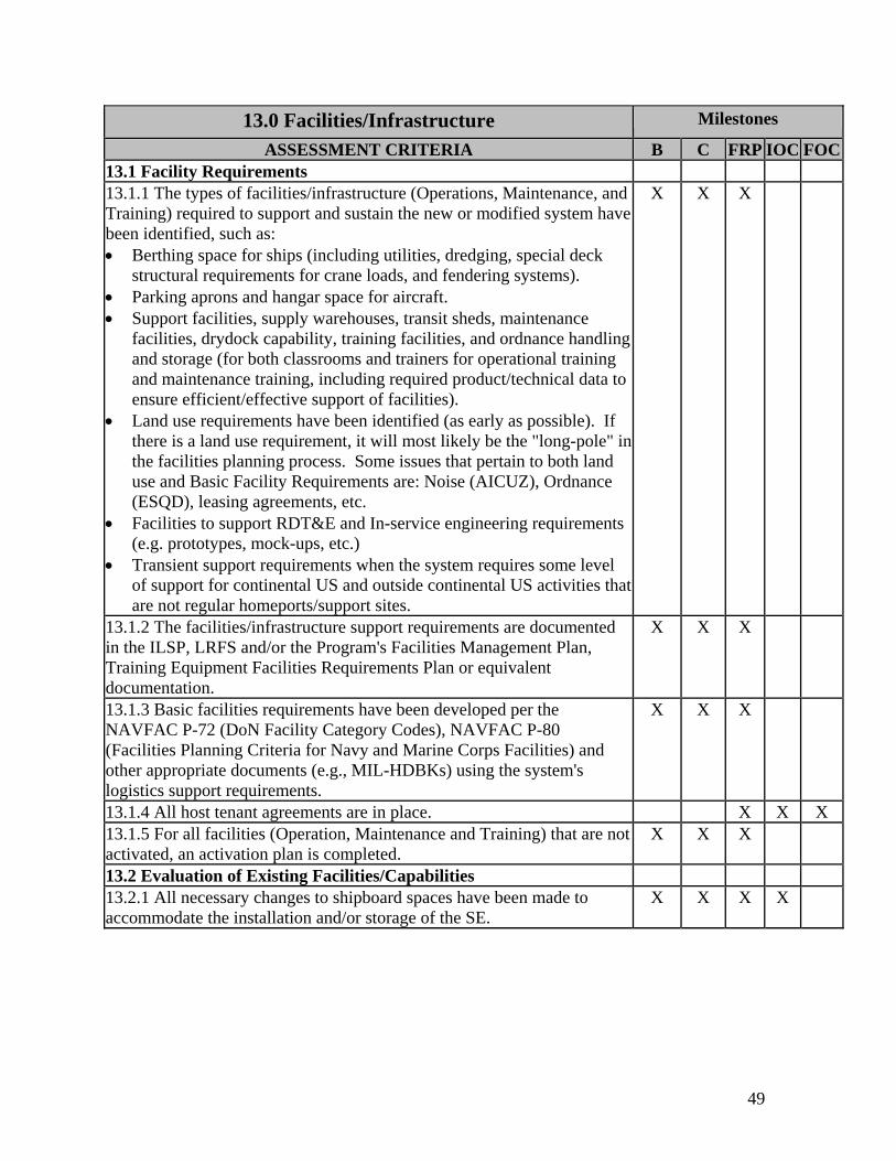
49
13.0 Facilities/Infrastructure Milestones
ASSESSMENT CRITERIA B C FRP IOC FOC13.1 Facility Requirements 13.1.1 The types of facilities/infrastructure (Operations, Maintenance, and Training) required to support and sustain the new or modified system have been identified, such as: • Berthing space for ships (including utilities, dredging, special deck
structural requirements for crane loads, and fendering systems). • Parking aprons and hangar space for aircraft. • Support facilities, supply warehouses, transit sheds, maintenance
facilities, drydock capability, training facilities, and ordnance handling and storage (for both classrooms and trainers for operational training and maintenance training, including required product/technical data to ensure efficient/effective support of facilities).
• Land use requirements have been identified (as early as possible). If there is a land use requirement, it will most likely be the "long-pole" in the facilities planning process. Some issues that pertain to both land use and Basic Facility Requirements are: Noise (AICUZ), Ordnance (ESQD), leasing agreements, etc.
• Facilities to support RDT&E and In-service engineering requirements (e.g. prototypes, mock-ups, etc.)
• Transient support requirements when the system requires some level of support for continental US and outside continental US activities that are not regular homeports/support sites.
X X X
13.1.2 The facilities/infrastructure support requirements are documented in the ILSP, LRFS and/or the Program's Facilities Management Plan, Training Equipment Facilities Requirements Plan or equivalent documentation.
X X X
13.1.3 Basic facilities requirements have been developed per the NAVFAC P-72 (DoN Facility Category Codes), NAVFAC P-80 (Facilities Planning Criteria for Navy and Marine Corps Facilities) and other appropriate documents (e.g., MIL-HDBKs) using the system's logistics support requirements.
X X X
13.1.4 All host tenant agreements are in place. X X X 13.1.5 For all facilities (Operation, Maintenance and Training) that are not activated, an activation plan is completed.
X X X
13.2 Evaluation of Existing Facilities/Capabilities 13.2.1 All necessary changes to shipboard spaces have been made to accommodate the installation and/or storage of the SE.
X X X X
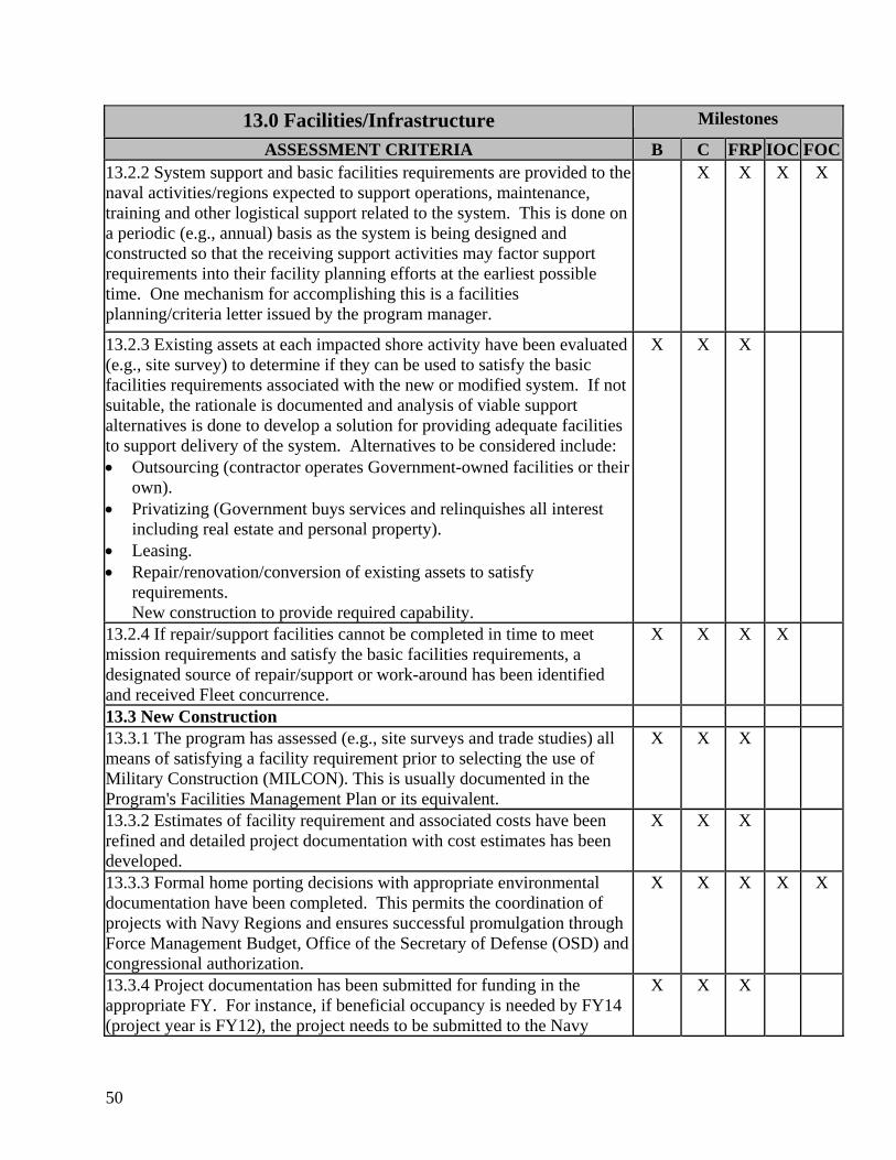
50
13.0 Facilities/Infrastructure Milestones
ASSESSMENT CRITERIA B C FRP IOC FOC13.2.2 System support and basic facilities requirements are provided to the naval activities/regions expected to support operations, maintenance, training and other logistical support related to the system. This is done on a periodic (e.g., annual) basis as the system is being designed and constructed so that the receiving support activities may factor support requirements into their facility planning efforts at the earliest possible time. One mechanism for accomplishing this is a facilities planning/criteria letter issued by the program manager.
X X X X
13.2.3 Existing assets at each impacted shore activity have been evaluated (e.g., site survey) to determine if they can be used to satisfy the basic facilities requirements associated with the new or modified system. If not suitable, the rationale is documented and analysis of viable support alternatives is done to develop a solution for providing adequate facilities to support delivery of the system. Alternatives to be considered include: • Outsourcing (contractor operates Government-owned facilities or their
own). • Privatizing (Government buys services and relinquishes all interest
including real estate and personal property). • Leasing. • Repair/renovation/conversion of existing assets to satisfy
requirements. New construction to provide required capability.
X X X
13.2.4 If repair/support facilities cannot be completed in time to meet mission requirements and satisfy the basic facilities requirements, a designated source of repair/support or work-around has been identified and received Fleet concurrence.
X X X X
13.3 New Construction 13.3.1 The program has assessed (e.g., site surveys and trade studies) all means of satisfying a facility requirement prior to selecting the use of Military Construction (MILCON). This is usually documented in the Program's Facilities Management Plan or its equivalent.
X X X
13.3.2 Estimates of facility requirement and associated costs have been refined and detailed project documentation with cost estimates has been developed.
X X X
13.3.3 Formal home porting decisions with appropriate environmental documentation have been completed. This permits the coordination of projects with Navy Regions and ensures successful promulgation through Force Management Budget, Office of the Secretary of Defense (OSD) and congressional authorization.
X X X X X
13.3.4 Project documentation has been submitted for funding in the appropriate FY. For instance, if beneficial occupancy is needed by FY14 (project year is FY12), the project needs to be submitted to the Navy
X X X

51
13.0 Facilities/Infrastructure Milestones
ASSESSMENT CRITERIA B C FRP IOC FOCRegion by the second quarter of FY09. 13.3.5 Environmental documentation for projects per NEPA/EO 12114 is either complete or scheduled for completion to support the timelines for new construction or modification of existing facilities.
X X X
13.3.6 For construction or alterations not classified as MILCON, funding has been identified to support the project and contract award is tracking in a manner supportive of the ultimate need date.
X X X X
13.3.7 Projects classified as MILCON are included in the Navy's Integrated Project List (IPL) and are on track for congressional authorization.
X X X X
13.3.8 Equipment (e.g. simulators, Air Traffic Control, Magnetic Silencing equip., etc.) has been identified and budgeted in the appropriate FY. Its procurement is on track to support project completion schedules.
X X X X
13.3.9 Construction of MILCON projects have been initiated and are on track to support introduction of the new or modified system to the Fleet.
X X X X
13.3.10 Where applicable, interim facility support (aka "work-around") has been identified to meet requirements earlier than can be met by the completion of new facility projects.
X X X X

52
This page blank
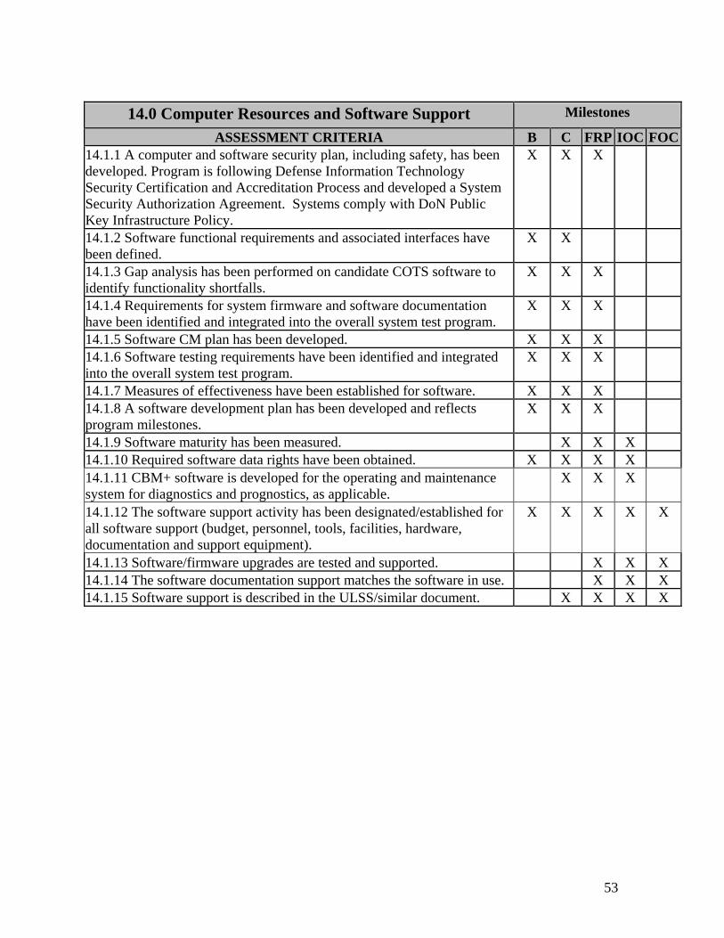
53
14.0 Computer Resources and Software Support Milestones
ASSESSMENT CRITERIA B C FRP IOC FOC14.1.1 A computer and software security plan, including safety, has been developed. Program is following Defense Information Technology Security Certification and Accreditation Process and developed a System Security Authorization Agreement. Systems comply with DoN Public Key Infrastructure Policy.
X X X
14.1.2 Software functional requirements and associated interfaces have been defined.
X X
14.1.3 Gap analysis has been performed on candidate COTS software to identify functionality shortfalls.
X X X
14.1.4 Requirements for system firmware and software documentation have been identified and integrated into the overall system test program.
X X X
14.1.5 Software CM plan has been developed. X X X 14.1.6 Software testing requirements have been identified and integrated into the overall system test program.
X X X
14.1.7 Measures of effectiveness have been established for software. X X X 14.1.8 A software development plan has been developed and reflects program milestones.
X X X
14.1.9 Software maturity has been measured. X X X 14.1.10 Required software data rights have been obtained. X X X X 14.1.11 CBM+ software is developed for the operating and maintenance system for diagnostics and prognostics, as applicable.
X X X
14.1.12 The software support activity has been designated/established for all software support (budget, personnel, tools, facilities, hardware, documentation and support equipment).
X X X X X
14.1.13 Software/firmware upgrades are tested and supported. X X X 14.1.14 The software documentation support matches the software in use. X X X 14.1.15 Software support is described in the ULSS/similar document. X X X X

54
This page blank
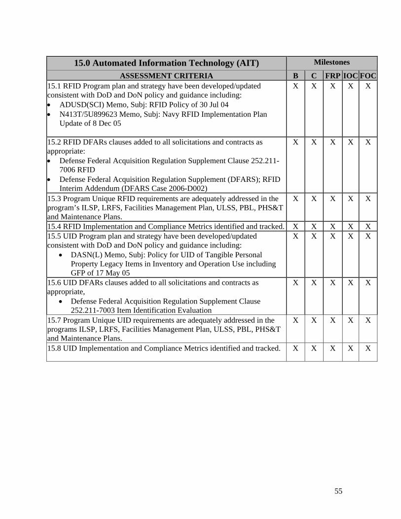
55
15.0 Automated Information Technology (AIT) Milestones
ASSESSMENT CRITERIA B C FRP IOC FOC15.1 RFID Program plan and strategy have been developed/updated consistent with DoD and DoN policy and guidance including: • ADUSD(SCI) Memo, Subj: RFID Policy of 30 Jul 04 • N413T/5U899623 Memo, Subj: Navy RFID Implementation Plan
Update of 8 Dec 05
X X X X X
15.2 RFID DFARs clauses added to all solicitations and contracts as appropriate: • Defense Federal Acquisition Regulation Supplement Clause 252.211-
7006 RFID • Defense Federal Acquisition Regulation Supplement (DFARS); RFID
Interim Addendum (DFARS Case 2006-D002)
X X X X X
15.3 Program Unique RFID requirements are adequately addressed in the program’s ILSP, LRFS, Facilities Management Plan, ULSS, PBL, PHS&T and Maintenance Plans.
X X X X X
15.4 RFID Implementation and Compliance Metrics identified and tracked. X X X X X 15.5 UID Program plan and strategy have been developed/updated consistent with DoD and DoN policy and guidance including:
• DASN(L) Memo, Subj: Policy for UID of Tangible Personal Property Legacy Items in Inventory and Operation Use including GFP of 17 May 05
X X X X X
15.6 UID DFARs clauses added to all solicitations and contracts as appropriate,
• Defense Federal Acquisition Regulation Supplement Clause 252.211-7003 Item Identification Evaluation
X X X X X
15.7 Program Unique UID requirements are adequately addressed in the programs ILSP, LRFS, Facilities Management Plan, ULSS, PBL, PHS&T and Maintenance Plans.
X X X X X
15.8 UID Implementation and Compliance Metrics identified and tracked. X X X X X

56
This page blank
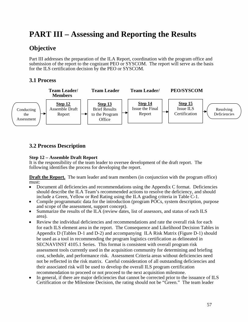
57
PART III – Assessing and Reporting the Results Objective Part III addresses the preparation of the ILA Report, coordination with the program office and submission of the report to the cognizant PEO or SYSCOM. The report will serve as the basis for the ILS certification decision by the PEO or SYSCOM. 3.1 Process Team Leader/ Team Leader Team Leader/ PEO/SYSCOM Members 3.2 Process Description Step 12 – Assemble Draft Report It is the responsibility of the team leader to oversee development of the draft report. The following identifies the process for developing the report. Draft the Report. The team leader and team members (in conjunction with the program office) must: • Document all deficiencies and recommendations using the Appendix C format. Deficiencies
should describe the ILA Team’s recommended actions to resolve the deficiency, and should include a Green, Yellow or Red Rating using the ILA grading criteria in Table C-1.
• Compile programmatic data for the introduction (program POCs, system description, purpose and scope of the assessment, support concept).
• Summarize the results of the ILA (review dates, list of assessors, and status of each ILS area).
• Review the individual deficiencies and recommendations and rate the overall risk for each for each ILS element area in the report. The Consequence and Likelihood Decision Tables in Appendix D (Tables D-1 and D-2) and accompanying ILA Risk Matrix (Figure D-1) should be used as a tool in recommending the program logistics certification as delineated in SECNAVINST 4105.1 Series. This format is consistent with overall program risk assessment tools currently used in the acquisition community for determining and briefing cost, schedule, and performance risk. Assessment Criteria areas without deficiencies need not be reflected in the risk matrix. Careful consideration of all outstanding deficiencies and their associated risk will be used to develop the overall ILS program certification recommendation to proceed or not proceed to the next acquisition milestone.
• In general, if there are major deficiencies that cannot be corrected prior to the issuance of ILS Certification or the Milestone Decision, the rating should not be “Green.” The team leader
Step 13 Brief Results
to the Program Office
Step 14 Issue the Final
Report
Step 15 Issue ILS
Certification
Step 12 Assemble Draft
Report Conducting
the Assessment
Resolving Deficiencies
58
should brief the program manager prior to release of the final ILA Report on each deficiency and recommendation as well as the team leader's recommendation for logistics certification.
• Draw conclusions regarding the program’s ILS posture/risks in terms of its ability to: 1. meet established performance metrics, 2. have achievable interim support plans, 3. be fully supportable at system IOC, 4. meet other support requirements and milestones.
• Draw recommendations regarding the program’s preparation to proceed into the next phase. The report must reflect a clear distinction between issues requiring resolution prior to the milestone decision and issues that may be resolved after the milestone at specific timeframes (e.g. prior to contract award or release of the request for proposal, or prior to Fleet introduction or operational evaluation, etc.). As the report is being drafted, the Program Manager provides a formal POA&M to address each deficiency identified in the ILA report. POA&Ms should be submitted and included in the final report, if possible. If they are not finalized prior to issuance of the final report, they will be provided to the team leader at a mutually agreed to time. All proposed actions should address funding availability and support overall program milestones. The team leader, in consultation with respective team members, shall review and respond to the proposed POA&Ms, ensuring adequacy and appropriateness of the planned actions. The ILA Report Format is identified in Appendix D. Step 13 – Brief Results to the Program Office. The team leader provides the program manager, logistics manager and other key program office personnel the draft results of the assessment to ensure the content of the report is accurate and understood. The team leader discusses the following: • Assessment overview. • Summary of each deficiency. • Rating for the program, including individual assessments and overall program rating • Concurrence from the Program Office • Any follow-up discussions on issues requiring action plans. • Coordination of the final report prior to formal issuance
Step 14 – Issue the Final Report. The team leader incorporates any changes or corrections resulting from discussions with the program office during Step 13 and forwards the final report, to include the final risk matrix and assessment criteria color summary, to his signature authority as appropriate. The final report is forwarded to the applicable Program Manager and PEO/SYSCOM Commander and other addressees highlighted in SECNAVINST 4105.1 Series. For joint programs, a courtesy copy of the ILA report should also be provided to other affected Service’s PEO and/or Acquisition Executive. Step 15 – Issue ILS Certification. Upon receipt of the final report, the cognizant PEO/SYSCOM Commander will review the report and certify the ILS program as Ready to Proceed, Conditionally Ready to Proceed, or Not Ready to Proceed in accordance with SECNAVINST 4105.1 Series. The associated certification letter will be issued in accordance with SECNAVINST 4105.1 Series.
3.3 Process Deliverables • ILA Report, including POAM • ILS Certification Letter

59
PART IV - Resolving Deficiencies Objective The objective of Part IV is to ensure the deficiencies identified in the assessment report are adequately resolved. This is one of the most important tasks in the entire ILA process. If deficiencies in planning, funding, or execution are only documented and not resolved, the end user will not received necessary ILS products. To ensure deficiencies are adequately resolved, the ILA team leader must remain engaged with the Program Office until completion of each deficiency can be independently verified. 4.1 Process Team Leader/ PEO/ PM SYSCOM 4.2 Process Description Step 16 – Tracking/Closing Actions. The responsibility for implementing and completing corrective actions remains with the Program Manager. Written status of the actions in the POA&M must be provided to the ILA Team Leader. The periodicity of these status reports will be as agreed to between the Project Management Office and the team leader. The final responsibility for closing ILA deficiencies remains with the team leader, who should consult with the originator of a deficiency prior to closing it.
Step 17 – Close Assessment. The ILA team leader must remain engaged with the Program Manager to ensure all POA&M actions are completed. Once all deficiencies have been satisfactorily resolved, as agreed to by the team leader, the ILA may be closed and final ILS certification issued. 4.3 Process Deliverables • Status reports • Team Leader responses/guidance to status reports • Final ILS Certification (if appropriate)
Step 16 Tracking /
Closing Actions
Step 17 Close
Assessment Assessing and
Reporting Results END

60
This page blank
Appendix A - Documentation Request List

A-2
This page blank
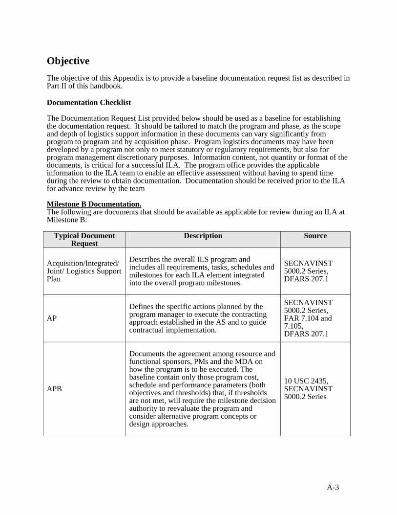
A-3
Objective The objective of this Appendix is to provide a baseline documentation request list as described in Part II of this handbook. Documentation Checklist The Documentation Request List provided below should be used as a baseline for establishing the documentation request. It should be tailored to match the program and phase, as the scope and depth of logistics support information in these documents can vary significantly from program to program and by acquisition phase. Program logistics documents may have been developed by a program not only to meet statutory or regulatory requirements, but also for program management discretionary purposes. Information content, not quantity or format of the documents, is critical for a successful ILA. The program office provides the applicable information to the ILA team to enable an effective assessment without having to spend time during the review to obtain documentation. Documentation should be received prior to the ILA for advance review by the team Milestone B Documentation. The following are documents that should be available as applicable for review during an ILA at Milestone B:
Typical Document Request
Description Source
Acquisition/Integrated/ Joint/ Logistics Support Plan
Describes the overall ILS program and includes all requirements, tasks, schedules and milestones for each ILA element integrated into the overall program milestones.
SECNAVINST 5000.2 Series, DFARS 207.1
AP
Defines the specific actions planned by the program manager to execute the contracting approach established in the AS and to guide contractual implementation.
SECNAVINST 5000.2 Series, FAR 7.104 and 7.105, DFARS 207.1
APB
Documents the agreement among resource and functional sponsors, PMs and the MDA on how the program is to be executed. The baseline contain only those program cost, schedule and performance parameters (both objectives and thresholds) that, if thresholds are not met, will require the milestone decision authority to reevaluate the program and consider alternative program concepts or design approaches.
10 USC 2435, SECNAVINST 5000.2 Series
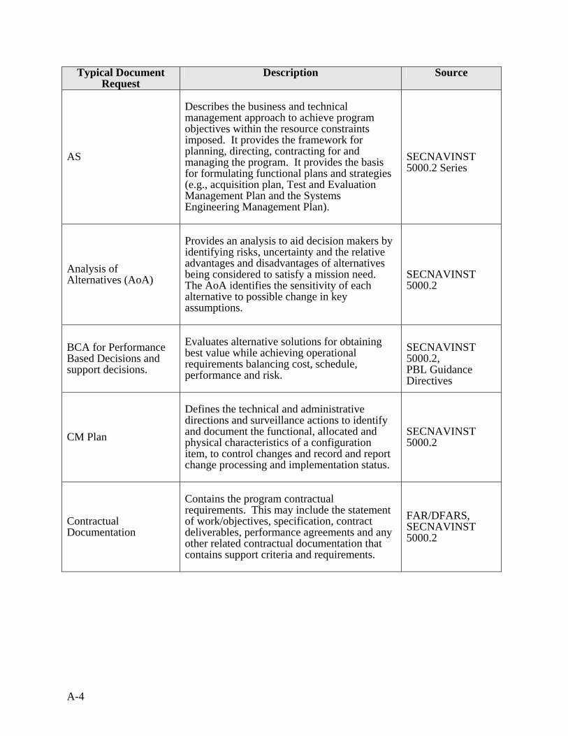
A-4
Typical Document Request
Description Source
AS
Describes the business and technical management approach to achieve program objectives within the resource constraints imposed. It provides the framework for planning, directing, contracting for and managing the program. It provides the basis for formulating functional plans and strategies (e.g., acquisition plan, Test and Evaluation Management Plan and the Systems Engineering Management Plan).
SECNAVINST 5000.2 Series
Analysis of Alternatives (AoA)
Provides an analysis to aid decision makers by identifying risks, uncertainty and the relative advantages and disadvantages of alternatives being considered to satisfy a mission need. The AoA identifies the sensitivity of each alternative to possible change in key assumptions.
SECNAVINST 5000.2
BCA for Performance Based Decisions and support decisions.
Evaluates alternative solutions for obtaining best value while achieving operational requirements balancing cost, schedule, performance and risk.
SECNAVINST 5000.2, PBL Guidance Directives
CM Plan
Defines the technical and administrative directions and surveillance actions to identify and document the functional, allocated and physical characteristics of a configuration item, to control changes and record and report change processing and implementation status.
SECNAVINST 5000.2
Contractual Documentation
Contains the program contractual requirements. This may include the statement of work/objectives, specification, contract deliverables, performance agreements and any other related contractual documentation that contains support criteria and requirements.
FAR/DFARS, SECNAVINST 5000.2

A-5
Typical Document Request
Description Source
Cost Analysis Requirements Description
Describes the complete program and used as the basis for program office and Component cost analysis teams to prepare program life cycle cost estimates. It should be comprehensive enough to facilitate identification of any area or issue that could have a significant effect on life-cycle costs and therefore must be addressed in the cost analysis. It also must be flexible enough to accommodate the use of various estimation methodologies.
SECNAVINST 5000.2
DMSMS Element focused on overcoming the loss, or impending loss, of manufacturers or suppliers of critical items and raw material.
DASN (L) Memo 12 Apr 05 DoD 4140.1-R (5/23/03)
DRMP
Provides a time history or profile of events, functions (often referred to as use or operations) and environmental conditions that a system is expected to encounter during its life cycle, from manufacturing to removal from service use.
SECNAVINST 5000.2, DFARS 207.1
Facilities Plan
Describes the plan to develop, identify and implement facility requirements to maintain, operate and test an item and to train personnel for its use.
SECNAVINST 5000.2, NAVFAC P-72, NAVFAC P-80, OPNAVINST 11102.1
HSI Plan
Describes how the system will meet the needs of the human operators, maintainers, and support personnel. This includes MPT&E, HFE, personnel survivability, and habitability. Also describes how the program will meet HSI programmatic requirements and standards including analysis to reduce manpower, improve human performance, and minimize personnel risk. HSI is the integrated analysis, design, and assessment over the life-cycle of a system and associated support infrastructure in the domains of MPT&E, HFE, personnel survivability, habitability, safety, and occupational health.
SECNAVINST 5000.2

A-6
Typical Document Request
Description Source
Information Support Plan (ISP)
Identifies ISP needs, dependencies and interfaces focusing on interoperability, supportability, and sufficiency concerns throughout a programs’ life cycle. It provides a plan for ACAT programs, including both information technology and national security systems that connect to the communications and information infrastructure.
DoDI 4630.8, DoDD 4630.5, CJCSI 6212.01, DoDI 5000.2
ICD and CDD
Guides the Concept Refinement and Technology Development phases of the acquisition process and supports the Milestone A decision. The ICD includes a description of the operational capability gap, threat, shortcomings of existing systems and Command, Control Communications Computers and Intelligence (C4I) architectures, capabilities required for the system, program support, force structure, Doctrine, Organization, Training, Material, Leadership and Education, Personnel and Facilities analysis and schedule/program affordability for the system. Replaces the mission needs statement. Includes the operational performance parameters necessary for the acquisition community to design a proposed system and establish a program baseline. The performance attributes stated include key performance parameters, thresholds and objectives to guide the development and demonstration of the proposed increment. Equivalent to the operational requirements document.
CJCSINST 3170.01, SECNAVINST 5000.2
Integrated Master/ Management Plan
Depicts the overall structure of the program and the key processes, activities and milestones in an event-based plan. It defines the accomplishments and criteria for each event in the plan.
MIL-HDBK-881, IPPD best practice, Defense Acquisition Guidebook
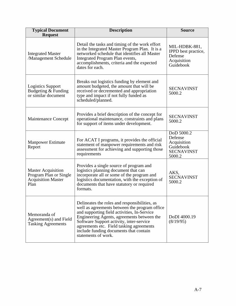
A-7
Typical Document Request
Description Source
Integrated Master /Management Schedule
Detail the tasks and timing of the work effort in the Integrated Master Program Plan. It is a networked schedule that identifies all Master Integrated Program Plan events, accomplishments, criteria and the expected dates for each.
MIL-HDBK-881, IPPD best practice, Defense Acquisition Guidebook
Logistics Support Budgeting & Funding or similar document
Breaks out logistics funding by element and amount budgeted, the amount that will be received or decremented and appropriation type and impact if not fully funded as scheduled/planned.
SECNAVINST 5000.2
Maintenance Concept
Provides a brief description of the concept for operational maintenance, constraints and plans for support of items under development.
SECNAVINST 5000.2
Manpower Estimate Report
For ACAT I programs, it provides the official statement of manpower requirements and risk assessment for achieving and supporting those requirements
DoD 5000.2 Defense Acquisition Guidebook SECNAVINST 5000.2
Master Acquisition Program Plan or Single Acquisition Master Plan
Provides a single source of program and logistics planning document that can incorporate all or some of the program and logistics documentation, with the exception of documents that have statutory or required formats.
AKS, SECNAVINST 5000.2
Memoranda of Agreement(s) and Field Tasking Agreements
Delineates the roles and responsibilities, as well as agreements between the program office and supporting field activities, In-Service Engineering Agents, agreements between the Software Support activity, inter-service agreements etc. Field tasking agreements include funding documents that contain statements of work.
DoDI 4000.19 (8/19/95)
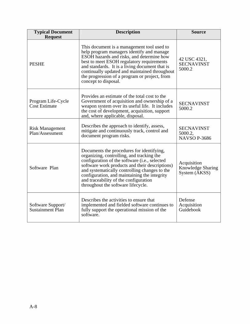
A-8
Typical Document Request
Description Source
PESHE
This document is a management tool used to help program managers identify and manage ESOH hazards and risks, and determine how best to meet ESOH regulatory requirements and standards. It is a living document that is continually updated and maintained throughout the progression of a program or project, from concept to disposal.
42 USC 4321, SECNAVINST 5000.2
Program Life-Cycle Cost Estimate
Provides an estimate of the total cost to the Government of acquisition and ownership of a weapon system over its useful life. It includes the cost of development, acquisition, support and, where applicable, disposal.
SECNAVINST 5000.2
Risk Management Plan/Assessment
Describes the approach to identify, assess, mitigate and continuously track, control and document program risks.
SECNAVINST 5000.2, NAVSO P-3686
Software Plan
Documents the procedures for identifying, organizing, controlling, and tracking the configuration of the software (i.e., selected software work products and their descriptions) and systematically controlling changes to the configuration, and maintaining the integrity and traceability of the configuration throughout the software lifecycle.
Acquisition Knowledge Sharing System (AKSS)
Software Support/ Sustainment Plan
Describes the activities to ensure that implemented and fielded software continues to fully support the operational mission of the software.
Defense Acquisition Guidebook
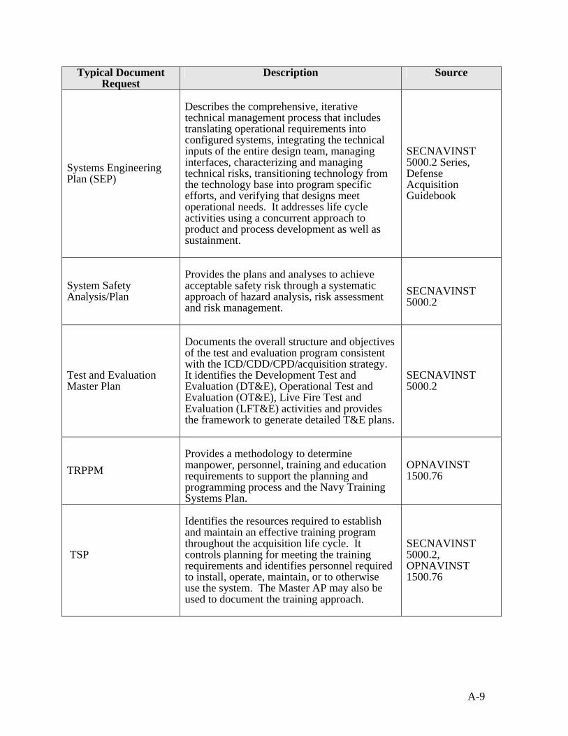
A-9
Typical Document Request
Description Source
Systems Engineering Plan (SEP)
Describes the comprehensive, iterative technical management process that includes translating operational requirements into configured systems, integrating the technical inputs of the entire design team, managing interfaces, characterizing and managing technical risks, transitioning technology from the technology base into program specific efforts, and verifying that designs meet operational needs. It addresses life cycle activities using a concurrent approach to product and process development as well as sustainment.
SECNAVINST 5000.2 Series, Defense Acquisition Guidebook
System Safety Analysis/Plan
Provides the plans and analyses to achieve acceptable safety risk through a systematic approach of hazard analysis, risk assessment and risk management.
SECNAVINST 5000.2
Test and Evaluation Master Plan
Documents the overall structure and objectives of the test and evaluation program consistent with the ICD/CDD/CPD/acquisition strategy. It identifies the Development Test and Evaluation (DT&E), Operational Test and Evaluation (OT&E), Live Fire Test and Evaluation (LFT&E) activities and provides the framework to generate detailed T&E plans.
SECNAVINST 5000.2
TRPPM
Provides a methodology to determine manpower, personnel, training and education requirements to support the planning and programming process and the Navy Training Systems Plan.
OPNAVINST 1500.76
TSP
Identifies the resources required to establish and maintain an effective training program throughout the acquisition life cycle. It controls planning for meeting the training requirements and identifies personnel required to install, operate, maintain, or to otherwise use the system. The Master AP may also be used to document the training approach.
SECNAVINST 5000.2, OPNAVINST 1500.76

A-10
Typical Document Request
Description Source
UID Plan
Describes the plan for encoding data matrix symbols that are applied to parts using a Direct Part Marking (DPM) process to facilitate electronic data capture and transmission. Data elements are then used to track parts throughout their life cycle.
DASN(L) Memo 17 May 05 USD(AT&L) Memo 23 Dec 04
Milestone C In addition to the documents listed in the “Milestone B” list, the following should be available as applicable for review during a Milestone C ILA.
Typical Document Request
Description Source
CPD
Narrows the generalized performance and cost parameters from the CDD into more precise performance estimates for the specific production system increment. The CPD is finalized after the design readiness review.
CJCSI 3170.01, SECNAVINST 5000.2
Computer Resources Life Cycle Management Plan
Describes the development, acquisition, test and support plans over the life cycle of computer resources integral to, or used in, direct support of systems. May be a part of the ILS Plan.
AKSS
COTS Refreshment plan/program
Defines the plan to avoid obsolescence in the delivered systems. The planning for technology refresh and insertion is a part of the systems engineering process and includes market research over the life of the system to identify potential replacements in anticipation of end-of-life issues.
Defense Acquisition Guidebook, AKSS
Development Test/ Operational Test Results
Provides results from developmental and operational testing on a system.
SECNAVINST 5000.2
FRACAS
A closed-loop system for the identification of hardware/software failures/discrepancies, their analyses to root cause, implementation of corrective actions to prevent recurrence and verification of their effectiveness. Recording of data should be comprehensive to provide an accurate database for analyses.
SECNAVINST 5000.2, AKSS
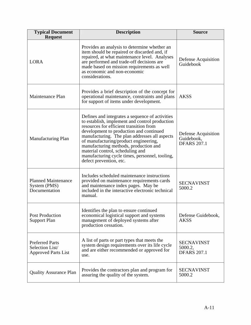
A-11
Typical Document Request
Description Source
LORA
Provides an analysis to determine whether an item should be repaired or discarded and, if repaired, at what maintenance level. Analyses are performed and trade-off decisions are made based on mission requirements as well as economic and non-economic considerations.
Defense Acquisition Guidebook
Maintenance Plan
Provides a brief description of the concept for operational maintenance, constraints and plans for support of items under development.
AKSS
Manufacturing Plan
Defines and integrates a sequence of activities to establish, implement and control production resources for efficient transition from development to production and continued manufacturing. The plan addresses all aspects of manufacturing/product engineering, manufacturing methods, production and material control, scheduling and manufacturing cycle times, personnel, tooling, defect prevention, etc.
Defense Acquisition Guidebook, DFARS 207.1
Planned Maintenance System (PMS) Documentation
Includes scheduled maintenance instructions provided on maintenance requirements cards and maintenance index pages. May be included in the interactive electronic technical manual.
SECNAVINST 5000.2
Post Production Support Plan
Identifies the plan to ensure continued economical logistical support and systems management of deployed systems after production cessation.
Defense Guidebook, AKSS
Preferred Parts Selection List/ Approved Parts List
A list of parts or part types that meets the system design requirements over its life cycle and are either recommended or approved for use.
SECNAVINST 5000.2, DFARS 207.1
Quality Assurance Plan Provides the contractors plan and program for assuring the quality of the system.
SECNAVINST 5000.2
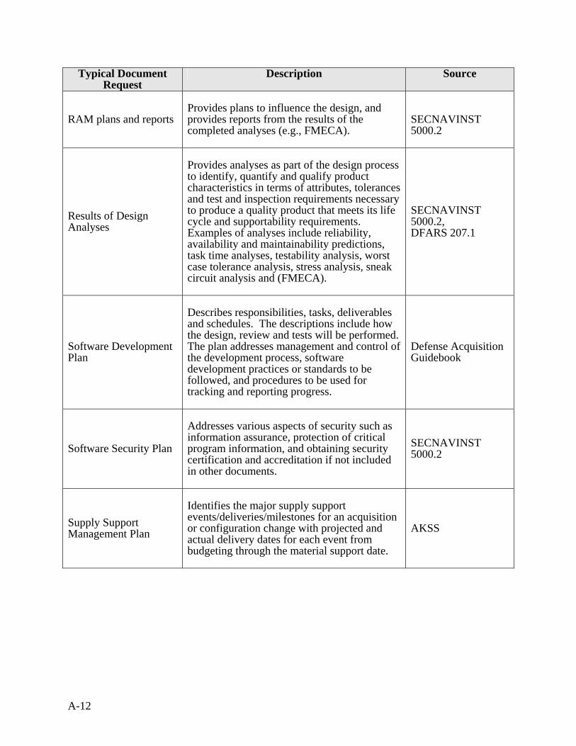
A-12
Typical Document Request
Description Source
RAM plans and reports
Provides plans to influence the design, and provides reports from the results of the completed analyses (e.g., FMECA).
SECNAVINST 5000.2
Results of Design Analyses
Provides analyses as part of the design process to identify, quantify and qualify product characteristics in terms of attributes, tolerances and test and inspection requirements necessary to produce a quality product that meets its life cycle and supportability requirements. Examples of analyses include reliability, availability and maintainability predictions, task time analyses, testability analysis, worst case tolerance analysis, stress analysis, sneak circuit analysis and (FMECA).
SECNAVINST 5000.2, DFARS 207.1
Software Development Plan
Describes responsibilities, tasks, deliverables and schedules. The descriptions include how the design, review and tests will be performed. The plan addresses management and control of the development process, software development practices or standards to be followed, and procedures to be used for tracking and reporting progress.
Defense Acquisition Guidebook
Software Security Plan
Addresses various aspects of security such as information assurance, protection of critical program information, and obtaining security certification and accreditation if not included in other documents.
SECNAVINST 5000.2
Supply Support Management Plan
Identifies the major supply support events/deliveries/milestones for an acquisition or configuration change with projected and actual delivery dates for each event from budgeting through the material support date.
AKSS
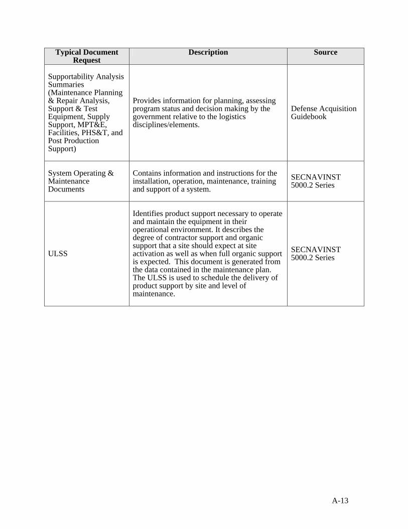
A-13
Typical Document Request
Description Source
Supportability Analysis Summaries (Maintenance Planning & Repair Analysis, Support & Test Equipment, Supply Support, MPT&E, Facilities, PHS&T, and Post Production Support)
Provides information for planning, assessing program status and decision making by the government relative to the logistics disciplines/elements.
Defense Acquisition Guidebook
System Operating & Maintenance Documents
Contains information and instructions for the installation, operation, maintenance, training and support of a system.
SECNAVINST 5000.2 Series
ULSS
Identifies product support necessary to operate and maintain the equipment in their operational environment. It describes the degree of contractor support and organic support that a site should expect at site activation as well as when full organic support is expected. This document is generated from the data contained in the maintenance plan. The ULSS is used to schedule the delivery of product support by site and level of maintenance.
SECNAVINST 5000.2 Series
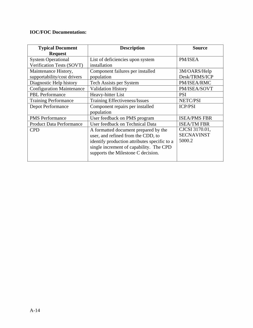
A-14
IOC/FOC Documentation:
Typical Document Request
Description Source
System Operational Verification Tests (SOVT)
List of deficiencies upon system installation
PM/ISEA
Maintenance History, supportability/cost drivers
Component failures per installed population
3M/OARS/Help Desk/TRMS/ICP
Diagnostic Help history Tech Assists per System PM/ISEA/RMC Configuration Maintenance Validation History PM/ISEA/SOVT PBL Performance Heavy-hitter List PSI Training Performance Training Effectiveness/Issues NETC/PSI Depot Performance Component repairs per installed
population ICP/PSI
PMS Performance User feedback on PMS program ISEA/PMS FBR Product Data Performance User feedback on Technical Data ISEA/TM FBR CPD
A formatted document prepared by the user, and refined from the CDD, to identify production attributes specific to a single increment of capability. The CPD supports the Milestone C decision.
CJCSI 3170.01, SECNAVINST 5000.2
Appendix B - Relationship between Reliability, Availability,
Maintainability and Logistics

B-2
This page blank
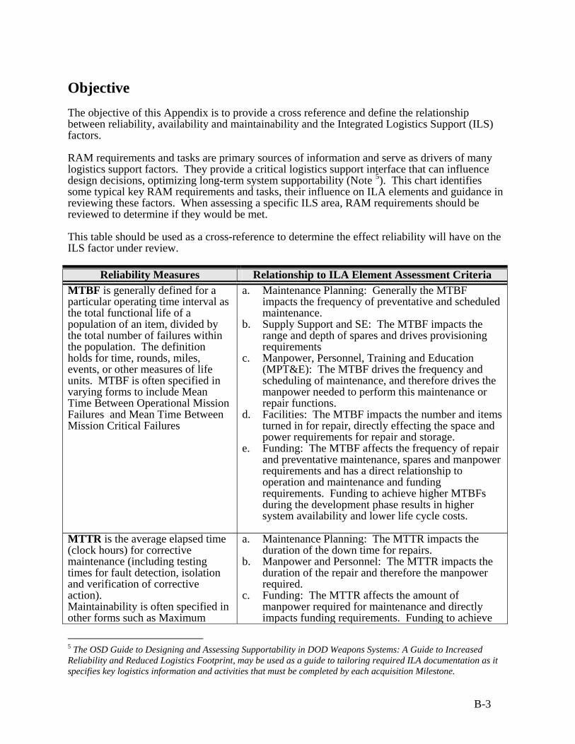
B-3
Objective The objective of this Appendix is to provide a cross reference and define the relationship between reliability, availability and maintainability and the Integrated Logistics Support (ILS) factors. RAM requirements and tasks are primary sources of information and serve as drivers of many logistics support factors. They provide a critical logistics support interface that can influence design decisions, optimizing long-term system supportability (Note 5). This chart identifies some typical key RAM requirements and tasks, their influence on ILA elements and guidance in reviewing these factors. When assessing a specific ILS area, RAM requirements should be reviewed to determine if they would be met. This table should be used as a cross-reference to determine the effect reliability will have on the ILS factor under review.
Reliability Measures Relationship to ILA Element Assessment Criteria MTBF is generally defined for a particular operating time interval as the total functional life of a population of an item, divided by the total number of failures within the population. The definition holds for time, rounds, miles, events, or other measures of life units. MTBF is often specified in varying forms to include Mean Time Between Operational Mission Failures and Mean Time Between Mission Critical Failures
a. Maintenance Planning: Generally the MTBF impacts the frequency of preventative and scheduled maintenance.
b. Supply Support and SE: The MTBF impacts the range and depth of spares and drives provisioning requirements
c. Manpower, Personnel, Training and Education (MPT&E): The MTBF drives the frequency and scheduling of maintenance, and therefore drives the manpower needed to perform this maintenance or repair functions.
d. Facilities: The MTBF impacts the number and items turned in for repair, directly effecting the space and power requirements for repair and storage.
e. Funding: The MTBF affects the frequency of repair and preventative maintenance, spares and manpower requirements and has a direct relationship to operation and maintenance and funding requirements. Funding to achieve higher MTBFs during the development phase results in higher system availability and lower life cycle costs.
MTTR is the average elapsed time (clock hours) for corrective maintenance (including testing times for fault detection, isolation and verification of corrective action). Maintainability is often specified in other forms such as Maximum
a. Maintenance Planning: The MTTR impacts the duration of the down time for repairs.
b. Manpower and Personnel: The MTTR impacts the duration of the repair and therefore the manpower required.
c. Funding: The MTTR affects the amount of manpower required for maintenance and directly impacts funding requirements. Funding to achieve
5 The OSD Guide to Designing and Assessing Supportability in DOD Weapons Systems: A Guide to Increased Reliability and Reduced Logistics Footprint, may be used as a guide to tailoring required ILA documentation as it specifies key logistics information and activities that must be completed by each acquisition Milestone.

B-4
Reliability Measures Relationship to ILA Element Assessment Criteria Time To Repair and Mean Corrective Maintenance Time for Operational Mission Failures).
lower MTTRs during the development phase results in higher system availability and lower life cycle costs.
MLDT is the average time a system is unavailable due to logistics system delays associated with the maintenance action (i.e., obtaining required parts (Mean Supply Response Time, (MSRT) or other logistics resources (Mean Administrative Delay Time (MADT), and Mean Outside Assistance Delay Time (MOADT) and other delays).
a. Maintenance Planning: The MLDT may drive the level of repair since the time to obtain spares may determine if the weapon system is spared at the system level or component level.
b. Supply Support: The amount of spares required is directly related to the off-station MLDT; the greater the off-station MLDT, the more spares will normally be required to be stored locally to meet availability requirements.
Ao is the percentage of time that a system will be ready to perform satisfactorily in its intended environment. It is generally defined as Up Time/(Up Time + Down Time) or,
MTBF (MTBF + MTTR + MLDT)
a. See MTBF, MTTR and MLDT for impact on logistics support elements.
b. Maintenance Planning: Ao analyses may assist in determining the optimum number of repair facilities depending on the maintenance and sparing concept.
System Analyses (FMECA), Single Point Failure Analysis (SPFA) and Fault Tree Analysis (FTA)) from the system level to the lowest part level are performed as the design progresses, to assess the design robustness and overall reliability. Worst Case Analyses are performed to identify tolerance stack-up as well as drift in circuit parameters. Calibration and measurement systems are included in these analyses.
a. Maintenance Planning and SE: These analyses assist in determining the failure effects which drive the trouble shooting criteria, strategy and equipment for fault detection of failure modes.
b. Supply Support: These analyses identify critical components and their failure modes so they can be adequately spared to optimize repair time and corrective action.
c. Product/Technical Documentation: These analyses will assist in determining the troubleshooting description, requirements and diagnostics in the technical documentation by identifying failures and their effects.
d. ESOH: These analyses may identify hazardous failure modes.
e. MPT&E: These analyses may identify specific manpower and training requirements for special operating and maintenance conditions/procedures.
f. Funding: Design changes or other corrective actions resulting from these analyses may reduce manufacturing, operation and maintenance cost. If these analyses are not performed, design deficiencies may not be identified until later during deployment, negatively affecting the program’s sustainment cost.
Sneak Circuit Analysis is performed to identify unintended
a. Maintenance Planning and SE: Results of the sneak circuit analysis will assist in determining the

B-5
Reliability Measures Relationship to ILA Element Assessment Criteria product operating modes and is performed as a minimum on critical circuits, circuits that perform frequent switching functions, and areas of safety concern.
troubleshooting and PMFL procedures by identifying potential sneak circuits and failure items.
b. ESOH: These analyses may identify failure modes that are hazardous.
c. Funding: These results are similar to the funding impacts found in Systems Analyses reliability measures.
Thermal Analysis is performed to identify thermal conditions that require corrective actions and includes results from analyses of the detail designs, thermal surveys/tests, and operational tests. Stress Analyses (mechanical/finite element, electrical, and thermal) are conducted to identify design margins and assess de-rating.
a. Supply Support and SE: These analyses identify potential compromised reliability and stressed items, which effect the sparing requirements.
b. ESOH: These analyses may identify failure modes that are hazardous.
a. Maintenance Planning: The results of these analyses may require special procedures to be followed during maintenance actions.
b. Funding: The results are similar to the funding impacts found in the Systems Analyses reliability measures.
Reliability Predictions/FRACAS is used to estimate the reliability of an item.
a. All ILS Areas: Provides information on whether the reliability (e.g., MTBF) will be achieved, exceeded or missed, so that adjustments can be made to sparing (supply support), maintenance planning, Manpower, Personnel, Training and Education requirements and PHS&T.
b. ESOH: These analyses identify failure rates to consider in determining criticality of hazards.
Design Limit/Life Testing − Qualification testing is
conducted to measure system hardware compliance with performance and design requirements.
− Accelerated life testing is conducted using higher than normal stresses to estimate the life of an item under normal operating conditions
− Step stress testing is a method of performing accelerated life testing to determine design margins by using progressively higher levels of stress.
a. Maintenance Planning: Test information is used in determining service life and technical refresh requirements.
b. Supply Support: Test information is used to substantiate reliability information that will determine spares requirements.
c. Funding: Design changes or other corrective actions resulting from these tests may reduce manufacturing, operation and maintenance cost. If these tests are not performed, design deficiencies may not be identified until later during deployment, negatively affecting the program’s sustainment cost.
Design for Testing/BIT objectives are to achieve the required performance monitoring, fault detection/localization and fault isolation capabilities at the appropriate maintenance levels with the optimum mix of BIT, semi-
a. Maintenance Planning: BIT effects testability and diagnostics by optimizing the efficiency of troubleshooting and fault isolation localization, and assist in determining the level of repair.
b. Supply Support: Properly designed BIT can reduce the demand for spares as a result of fewer false alarms.
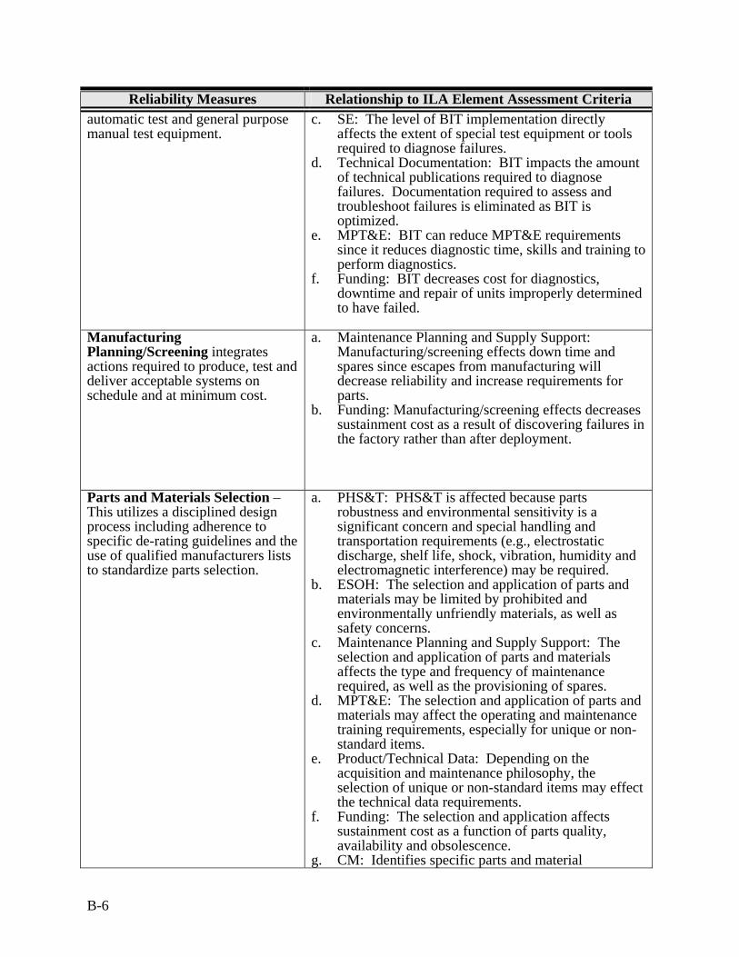
B-6
Reliability Measures Relationship to ILA Element Assessment Criteria automatic test and general purpose manual test equipment.
c. SE: The level of BIT implementation directly affects the extent of special test equipment or tools required to diagnose failures.
d. Technical Documentation: BIT impacts the amount of technical publications required to diagnose failures. Documentation required to assess and troubleshoot failures is eliminated as BIT is optimized.
e. MPT&E: BIT can reduce MPT&E requirements since it reduces diagnostic time, skills and training to perform diagnostics.
f. Funding: BIT decreases cost for diagnostics, downtime and repair of units improperly determined to have failed.
Manufacturing Planning/Screening integrates actions required to produce, test and deliver acceptable systems on schedule and at minimum cost.
a. Maintenance Planning and Supply Support: Manufacturing/screening effects down time and spares since escapes from manufacturing will decrease reliability and increase requirements for parts.
b. Funding: Manufacturing/screening effects decreases sustainment cost as a result of discovering failures in the factory rather than after deployment.
Parts and Materials Selection – This utilizes a disciplined design process including adherence to specific de-rating guidelines and the use of qualified manufacturers lists to standardize parts selection.
a. PHS&T: PHS&T is affected because parts robustness and environmental sensitivity is a significant concern and special handling and transportation requirements (e.g., electrostatic discharge, shelf life, shock, vibration, humidity and electromagnetic interference) may be required.
b. ESOH: The selection and application of parts and materials may be limited by prohibited and environmentally unfriendly materials, as well as safety concerns.
c. Maintenance Planning and Supply Support: The selection and application of parts and materials affects the type and frequency of maintenance required, as well as the provisioning of spares.
d. MPT&E: The selection and application of parts and materials may affect the operating and maintenance training requirements, especially for unique or non-standard items.
e. Product/Technical Data: Depending on the acquisition and maintenance philosophy, the selection of unique or non-standard items may effect the technical data requirements.
f. Funding: The selection and application affects sustainment cost as a function of parts quality, availability and obsolescence.
g. CM: Identifies specific parts and material
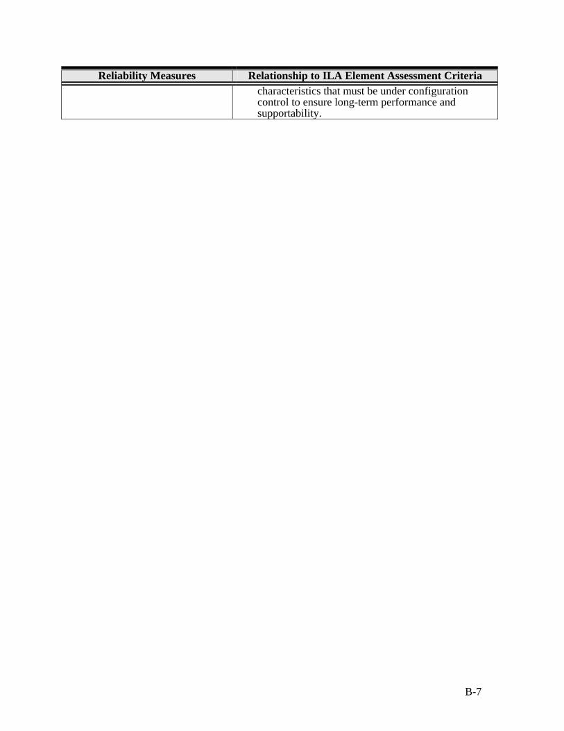
B-7
Reliability Measures Relationship to ILA Element Assessment Criteria characteristics that must be under configuration control to ensure long-term performance and supportability.

B-8
This page blank
Appendix C - ILA Deficiency/Recommendation Format

C-2
This page blank
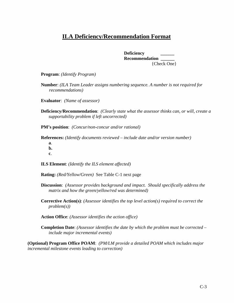
C-3
ILA Deficiency/Recommendation Format
Deficiency ______ Recommendation ______
{Check One} Program: (Identify Program) Number: (ILA Team Leader assigns numbering sequence. A number is not required for
recommendations) Evaluator: (Name of assessor) Deficiency/Recommendation: (Clearly state what the assessor thinks can, or will, create a
supportability problem if left uncorrected) PM’s position: (Concur/non-concur and/or rational) References: (Identify documents reviewed – include date and/or version number)
a. b. c.
ILS Element: (Identify the ILS element affected) Rating: (Red/Yellow/Green) See Table C-1 next page Discussion: (Assessor provides background and impact. Should specifically address the
matrix and how the green/yellow/red was determined) Corrective Action(s): (Assessor identifies the top level action(s) required to correct the
problem(s)) Action Office: (Assessor identifies the action office) Completion Date: (Assessor identifies the date by which the problem must be corrected –
include major incremental events)
(Optional) Program Office POAM: (PM/LM provide a detailed POAM which includes major incremental milestone events leading to correction)
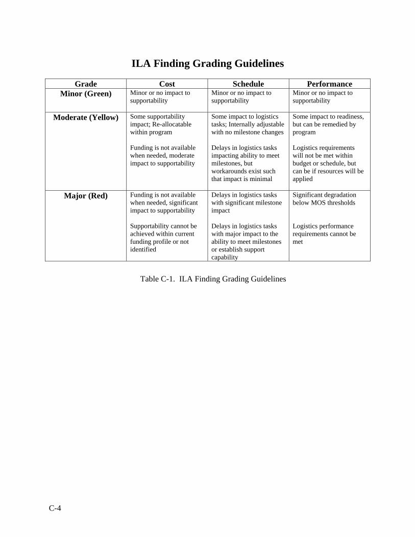
C-4
ILA Finding Grading Guidelines
Grade Cost Schedule Performance
Minor (Green) Minor or no impact to supportability
Minor or no impact to supportability
Minor or no impact to supportability
Moderate (Yellow) Some supportability impact; Re-allocatable within program Funding is not available when needed, moderate impact to supportability
Some impact to logistics tasks; Internally adjustable with no milestone changes Delays in logistics tasks impacting ability to meet milestones, but workarounds exist such that impact is minimal
Some impact to readiness, but can be remedied by program Logistics requirements will not be met within budget or schedule, but can be if resources will be applied
Major (Red) Funding is not available when needed, significant impact to supportability Supportability cannot be achieved within current funding profile or not identified
Delays in logistics tasks with significant milestone impact Delays in logistics tasks with major impact to the ability to meet milestones or establish support capability
Significant degradation below MOS thresholds Logistics performance requirements cannot be met
Table C-1. ILA Finding Grading Guidelines
D-1
Appendix D - ILA Report Format

D-2
This page blank
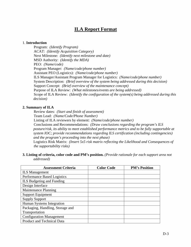
D-3
ILA Report Format
1. Introduction Program: (Identify Program) ACAT: (Identify Acquisition Category)
Next Milestone: (Identify next milestone and date) MSD Authority: (Identify the MDA) PEO: (Name/code) Program Manager: (Name/code/phone number) Assistant PEO (Logistics): (Name/code/phone number) ILS Manager/Assistant Program Manager for Logistics: (Name/code/phone number) System Description: (Brief overview of the system being addressed during this decision) Support Concept: (Brief overview of the maintenance concept) Purpose of ILA Review: (What milestones/events are being addressed) Scope of ILA Review: (Identify the configuration of the system(s) being addressed during this decision)
2. Summary of ILA Review dates: (Start and finish of assessment) Team Lead: (Name/Code/Phone Number)
Listing of ILA reviewers by element: (Name/code/phone number) Conclusions and Recommendations: (Draw conclusions regarding the program’s ILS posture/risk, its ability to meet established performance metrics and to be fully supportable at system IOC; provide recommendations regarding ILS certification (including contingencies) and the program’s proceeding into the next phase) Logistics Risk Matrix: (Insert 5x5 risk matrix reflecting the Likelihood and Consequences of the supportability risks)
3. Listing of criteria, color code and PM’s position. (Provide rationale for each support area not
addressed)
Assessment Criteria Color Code PM’s Position ILS Management Performance Based Logistics ILS Budgeting and Funding Design Interface Maintenance Planning Support Equipment Supply Support Human Systems Integration Packaging, Handling, Storage and Transportation
Configuration Management Product and Technical Data
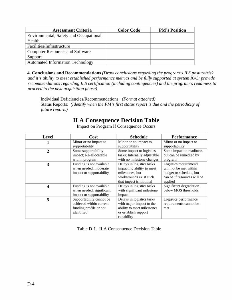
D-4
Assessment Criteria Color Code PM’s Position Environmental, Safety and Occupational Health
Facilities/Infrastructure Computer Resources and Software Support
Automated Information Technology 4. Conclusions and Recommendations (Draw conclusions regarding the program’s ILS posture/risk and it’s ability to meet established performance metrics and be fully supported at system IOC; provide recommendations regarding ILS certification (including contingencies) and the program’s readiness to proceed to the next acquisition phase)
Individual Deficiencies/Recommendations: (Format attached) Status Reports: (Identify when the PM’s first status report is due and the periodicity of future reports)
ILA Consequence Decision Table
Impact on Program If Consequence Occurs
Level Cost Schedule Performance 1 Minor or no impact to
supportability Minor or no impact to supportability
Minor or no impact to supportability
2 Some supportability impact; Re-allocatable within program
Some impact to logistics tasks; Internally adjustable with no milestone changes
Some impact to readiness, but can be remedied by program
3 Funding is not available when needed, moderate impact to supportability
Delays in logistics tasks impacting ability to meet milestones, but workarounds exist such that impact is minimal
Logistics requirements will not be met within budget or schedule, but can be if resources will be applied
4 Funding is not available when needed, significant impact to supportability
Delays in logistics tasks with significant milestone impact
Significant degradation below MOS thresholds
5 Supportability cannot be achieved within current funding profile or not identified
Delays in logistics tasks with major impact to the ability to meet milestones or establish support capability
Logistics performance requirements cannot be met
Table D-1. ILA Consequence Decision Table
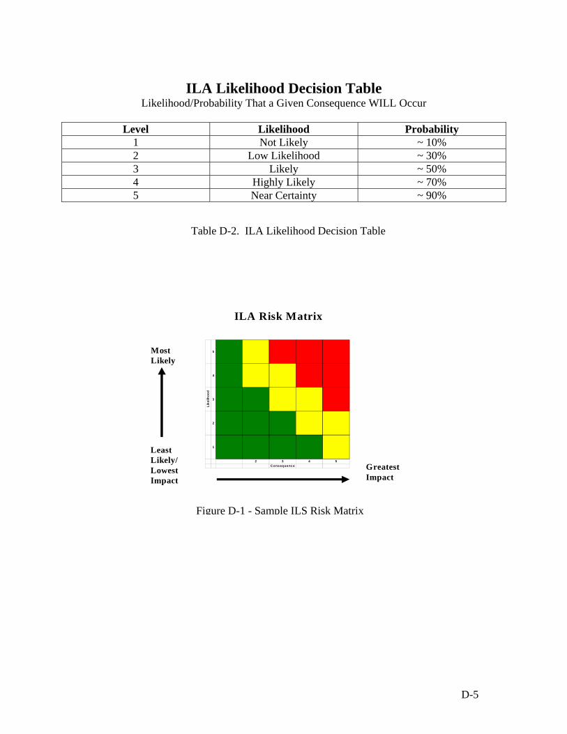
D-5
ILA Likelihood Decision Table
Likelihood/Probability That a Given Consequence WILL Occur
Level Likelihood Probability 1 Not Likely ~ 10% 2 Low Likelihood ~ 30% 3 Likely ~ 50% 4 Highly Likely ~ 70% 5 Near Certainty ~ 90%
Table D-2. ILA Likelihood Decision Table
5
4
Like
lihoo
d
3
2
1
2 3 4 5Consequence
ILA Risk Matrix
Most Likely
Least Likely/ Lowest Impact
Greatest Impact
Figure D-1 - Sample ILS Risk Matrix

D-6
This page blank
Appendix E - Glossary of Terms

E-2
This page blank
E-3
Automatic Identification Technology (AIT): AIT is the broad term given to a host of technologies that are used to help machines identify objects. Auto identification is often coupled with automatic data capture to identify items, capture information about them and somehow get the data into a computer without having employees type it in. The aim of most AIT and systems is to increase efficiency, reduce data entry errors and free up staff to perform more value-added functions, such as providing customer service. There is a host of technologies that fall under the AIT umbrella. These include bar codes, smart cards, voice recognition, some biometric technologies (retinal scans, for instance), Optical Character Recognition, RFID and UID. Acquisition Knowledge Sharing System (AKSS): Serves as the central point of access for all AT&L resources and information, and to communicate acquisition reform. As the primary reference tool for the Defense AT&L workforce, it provides a means to link together information and reference assets from various disciplines into an integrated, but decentralized information source. Authoritative Data Source: Data products including databases have been identified, described and designated by the appropriate Department of Navy Functional Data Managers, U.S. Military Services and Components as the authorized producer of data for a given requirement. Built-In-Test (BIT): Provides “Built-In” monitoring, fault detection and isolation capabilities as integral feature of the system design. It can be supplemented with imbedded expert system technology that incorporates diagnostic logic/strategies into the prime system. Business Case Analyses (BCA): The evaluation of alternative solutions for obtaining best value while achieving operational requirements balancing cost, schedule, performance and risk. Capabilities Development Document (CDD): A document that provides the operational performance attributes, including KPPs, necessary for the acquisition community to design a proposed system and establish a program baseline, normally using an evolutionary acquisition strategy. The CDD outlines an affordable increment of militarily useful, logistically supportable and technically mature capability that can be effectively developed, produced or acquired, deployed and sustained. The CDD supports the Milestone B acquisition decision. Capabilities Production Document (CPD): A document that addresses the information necessary to support production, testing and deployment of a specific affordable and supportable increment of an acquisition program. The refinement of performance attributes and KPPs is the most significant difference between the CDD and CPD. The CPD must be validated and approved before the Milestone C decision review. Condition Based Maintenance (CBM): A form of maintenance based on real time assessment of the system's condition, obtained from embedded sensors and/or external tests and measurements, to forecast incipient failures for corrective actions. Condition Based Maintenance Plus (CBM+): CBM+ expands on the CBM concept by encompassing other technologies, processes and procedures such as information system technologies that enable improved maintenance and logistics practices.
E-4
Configuration Item (CI): Any hardware, software, or combination of both that satisfies an end use function and is designated for separate configuration management. These may be functional, allocated or product configurations. Contractor Logistics Support (CLS): CLS is the performance of maintenance and/or material management functions for a system by a commercial activity. CLS is a product support strategy that can be selected for implementing PBL. Cost Per Unit Usage (CPUU): The total operating costs divided by the appropriate unit of measurement for a given weapon system. Depending on weapon system, the measurement unit could be flight hour, steaming hour, launch, mile driven, etc. Deficiency: Deficiencies are situations (planning, execution, funding, etc.) that constitute a risk of a program not being fully supportable and sustainable. More than one criterion may be grouped to a deficiency. Design Reference Mission Profile (DRMP): The DRMP provides the mission profile to which the system is designed. It includes the environmental profile; functional profiles and logistics use profiles. Diminishing Manufacturing Sources and Material Shortages (DMSMS): The loss or impending loss of the last known manufacturer or supplier of raw material, production parts, or repair parts. Full Operational Capability (FOC): In general, attained when all units and/or organizations in the force structure scheduled to receive a system that is fully mission capable 1) have received it and 2) have the ability to employ and maintain it. The specifics for any particular system FOC are defined in that system's CDD and CPD. Full Rate Production (FRP): Contracting for economic production quantities following stabilization of the system design and validation of the production process. This effort delivers the fully funded quantity of systems and supporting materiel and services for the program or increment to the users. During this effort, units shall attain IOC. Functional Configuration Audit (FCA): The formal examination of functional characteristics of a configuration item, or system to verify that the item has achieved the requirements specified in its functional and/or allocated configuration documentation. Gap Analysis: Assessment of the difference between a systems design, test, production and logistics mission requirements and available COTS/NDI equipment capabilities. Human Systems Integration: HSI integrates HFE; MP&TE; health hazards; safety factors; medical factors; personnel (or human) survivability factors; and habitability considerations into the system acquisition process.
E-5
Information Exchange Requirements (IER): The requirement for information to be passed between and among forces, organizations, or administrative structures concerning ongoing activities. IER requirements identify who exchanges what information with whom, as well as, why the information is necessary and how that information will be used. Information Interoperability: The exchange and use of information in any form, electronically, that enables effective operations for both war fighting and combat support areas both within the external activities, and synchronizes both material and non-material aspects. Information interoperability enables systems, units or forces to provide services to, and accept services from, other systems, units or forces, and to use the exchanged services to operate effectively together. Initial Capabilities Document (ICD): Documents the need for a materiel approach to a specific capability gap derived from an initial analysis of materiel approaches executed by the operational user and, as required, an independent analysis of materiel alternatives. It defines the capability gap in terms of the functional area, the relevant range of military operations, desired effects and time. The ICD supports the Milestone A acquisition decision, and subsequent Technology Development phase activities. Initial Operational Capability (IOC): In general, attained when some units and/or organizations in the force structure scheduled to receive a system that is partially mission capable 1) have received it and 2) have the ability to employ and maintain it. The specifics for any particular system IOC are defined in that system's CDD and CPD. Interactive Electronic Technical Manual (IETM): A computer-based collection of information needed for the operation, diagnosis and maintenance of a system. It is optically arranged and formatted for interactive presentation to the end user on an electronic display system. Unlike other optical systems that display a page of text from a single document, IETMs present interrelated information from multiple sources tailored to user queries. Item Unique Identification (IUID): IUID is the element of the DoD UID program that addresses tangible personal property. It provides a system for marking items delivered to and managed by the DoD with unique item identifiers in an ISO standard, ECC200 compliant machine readable form (2D Data Matrix) of Automatic Identification Technology (AIT). Key Performance Parameters (KPP): Those minimum attributes or characteristics considered most essential for an effective military capability. They characterize the major drivers of operational suitability, interoperability, supportability, schedule, technical progress and cost. Logistics Requirements Funding Summary (LRFS): The LRFS identifies the product support functions and sub-functions required to establish affordable and effective product support. It identifies support resource requirements and the funds available to meet those requirements. The summary displays requirements versus available funding for all ILS elements and related disciplines, by fiscal year and appropriation, and is traceable to logistic support plan tasks and activities.
E-6
Milestone B (MS B): The point at which a recommendation is made and approval sought regarding starting or continuing an acquisition program, i.e., proceeding to the next phase. MS B approval allows entry into the System Development and Demonstration (SDD) phase. SDD has two major efforts: System Integration and System Demonstration. The entrance point is MS B, which is also the initiation of an acquisition program. Milestone C (MS C): The point at which a recommendation is made and approval sought regarding continuing an acquisition program, i.e., proceeding to the next phase. MS C approval allows entry into the Production and Deployment phase. MS C authorizes entry into Low Rate Initial Production (LRIP) (for Major Defense Acquisition Programs and major systems), into production or procurement (for non-major systems that do not require LRIP) or into limited deployment in support of operational testing for Major Automated Information System programs or software-intensive systems with no production components. Performance Based Logistics (PBL): PBL is an agreement, usually long term, in which the provider (organic, commercial, and/or public/private partnership) is incentivized and empowered to meet overarching customer oriented performance requirements (reliability, availability, etc.) in order to improve product support effectiveness while reducing TOC. Performance Based Logistics Agreements: PBL support is usually documented in a contractual arrangement (commercial, organic or a combination of both) where the provider is held to customer oriented performance requirements, such as reliability improvement, availability improvement, and reduced delivery times with the end goal of improving logistics support to the warfighter. Physical Configuration Audit (PCA): The formal examination of the "as-built" configuration of a configuration item against its technical documentation to establish or verify the configuration item's product baseline. Conducted to verify that the as-built configuration item matches the design requirements of the conditionally approved engineering drawings, software design documents and product specifications. Product/Technical Data Package: A technical description of an item adequate for supporting an acquisition strategy, production, engineering, and logistics support. The description defines the required design configuration and procedures to ensure adequacy of item performance. It consists of all applicable technical data such as drawings, specifications, standards, manuals, performance requirements, quality assurance provisions, packaging details, etc. Documentation of computer programs and related software are technical data, while computer programs and related software are not. Recommendation: Suggested action(s) based on experience of assessors that would enhance or improve supportability and/or sustainability of a program. Reliability Centered Maintenance (RCM): A disciplined logic or methodology used to identify preventive and corrective maintenance tasks to realize the inherent reliability of equipment at a minimum expenditure of resources. Preventative maintenance requirements are developed to increase system availability/reliability by identifying and correcting failures or
E-7
potential failures before the system is degraded. The preventative maintenance may be based on time, material condition, failure rates or any combination. Radio Frequency Identification (RFID): RFID is a generic term for technologies that use radio waves to automatically identify people or objects. There are several methods of identification, but the most common is to store a serial number that identifies a person or object, and perhaps other information, on a microchip that is attached to an antenna (the chip and the antenna together are called an RFID transponder or an RFID tag). The antenna enables the chip to transmit the identification information to a reader. The reader converts the radio waves reflected back from the RFID tag into digital information that can then be passed on to computers that can make use of it. Total Life Cycle Systems Management (TLCSM): TLCSM is the implementation, management, and oversight, by the designated Program Manager, of all activities associated with the acquisition, development, production, fielding, sustainment and disposal of a weapon system across its life cycle. It empowers the program Manager as the life cycle manager with full accountability and responsibility for systems acquisition and follow-on sustainment. Total Ownership Cost (TOC): Includes all costs associated with the research, development, procurement, operation, logistics support and disposal of an individual weapon system, including the total supporting infrastructure that plans, manages and executes that weapon system program over its full life. Unique Identification (UID): DoD business transformation program for accountability and valuation of personal property, real property, and personnel including the tools and infrastructure for managing historical data, status of personnel and equipment and inter-organizational relationship. UID is a system of distinguishing one object from another, allowing DoD to track identical items individually throughout their lifecycles. Unique Item Identifier (UII): The set of data elements marked on an item in human readable and machine readable Automatic Identification Technology (AIT) form that is globally unique and unambiguous. Historically defined as the items pedigree and typically regarded as Part Number, Serial Number and Enterprise ID of the Original Equipment Manufacturer (i.e. Cage Code). User Logistics Support Summary (ULSS): The ULSS is prepared by the Program Manager for users to identify logistics resources necessary to operate and maintain the system, subsystems and equipment in their operational environment. The ULSS summarizes, in brief, the results of logistics planning and acquisition in the ILSP/ALSP. A separate ULSS may be required for each operating site.

E-8
This page blank
Appendix F - Glossary of Acronyms

F-2
This page blank
F-3
A
ACAT Acquisition Category AIT Automatic Identification Technology AKSS Acquisition Knowledge Sharing System ALSP Acquisition Logistics Support Plan Ao Operational Availability AoA Analysis of Alternatives APB Acquisition Program Baseline AS Acquisition Strategy ATIS Advanced Tactical Information System
B
BCA Business Case Analyses BIT Built-In-Test BOM Bill of Material
C
CBM Condition Based Maintenance CBM+ Condition Based Maintenance Plus CDD Capability Development Document CLS Contractor Logistics Support CM Configuration Management COSAL Coordinated Shipboard Allowance List COTS Commercial-Off-The Shelf CPD Capability Production Document CPUU Cost Per Unit Usage
D
DAWIA Defense Acquisition Workforce Improvement Act DFARS Defense Federal Acquisition Regulation Supplement DMSMS Diminishing Manufacturing Sources and Material Shortages DoD Department of Defense DoN Department of the Navy DRMP Design Reference Mission Profile
E
ESOH Environmental, Safety and Occupational Health EO Executive Order
F
F-4
FCA Functional Configuration Audit FMS Foreign Military Sales FMECA Failure Mode, Effects and Criticality Analysis FOC Full Operational Capability FRACAS Failure Reporting, Analysis and Corrective Action System FRP Full Rate Production
H HFE Human Factors Engineering HSI Human Systems Integration
I
ICD Initial Capabilities Document IDDE Integrated Digital Data Environment IETM Interactive Electronic Technical Manual ILA Independent Logistics Assessment ILSP Integrated Logistics Support Plan IOC Initial Operational Capability ISP Information Support Plan IUID Item Unique Identification
J
JMETL Joint Mission Essential Tasks Lists
K
KPP Key Performance Parameters
L
LSS Lean Six Sigma LORA Level of Repair Analysis LRIP Low Rate Initial Production LRFS Logistics Requirements Funding Summary
M
MAIS Major Automated Information System MDAP Major Defense Acquisition Programs MILCON Military Construction MLDT Mean Logistics Delay Time MPT&E Manpower, Personnel, Training and Education
F-5
MS B Milestone B MS C Milestone C MSD Material Support Date MTBF Mean Time Between Failure MTTR Mean Time To Repair
N
NDI Non-Development Item NEPA National Environmental Policy Act
O
OSD Office of the Secretary of Defense
P
PBA Performance Based Agreement PBL Performance Based Logistics PEO Program Executive Officer PESHE Program Environmental Safety and Health Evaluation PHS&T Packaging, Handling, Storage and Transport PMS Planned Maintenance System POA&M Plans of Actions and Milestones POC Point of Contact PRR Production Readiness Review PSI Product Support Integrator
R
RAM Reliability, Availability, and Maintainability RBS Readiness Based Spares RCCA Root Cause & Corrective Action RCM Reliability Centered Maintenance RFID Radio Frequency Identification RFP Request for Proposal
S
SDD System Development and Demonstration SE Support Equipment SOVT System Operational Verification Tests SOW Statement of Work SYSCOM Systems Command
F-6
T
TEMP Test and Evaluation Master Plan TPS Test Program Sets TLCSM Total Life Cycle Systems Management TOC Total Ownership Cost TRPPM Training Planning Process Methodology TSP Training System Planning
U
UID Unique Identification UII Unique Item Identification ULSS User Logistics Support Summary
V
W
WA Warfighter Agreement


![Documentary Storytelling DOCUMENTARY · 2019. 12. 23. · —The Independent (Association of ndependent Video and Filmmakers) “[B]rilliant and effective.” —BackStage Documentary](https://static.fdocuments.us/doc/165x107/60b92e9839a2b175ee592ee0/documentary-storytelling-documentary-2019-12-23-athe-independent-association.jpg)