i MERLIN MIABOT PRO ROBOT SOCCER (2 WHEELS)...
24
MERLIN MIABOT PRO ROBOT SOCCER (2 WHEELS) MUHAMMAD ASYRAF BIN BADARUDDIN This report is submitted in partial fulfillment of requirements for the award of Bachelor of Electronic Engineering (Computer Engineering) with Honours Faculty of Electronic and Computer Engineering Universiti Teknikal Malaysia Melaka (UTeM) May 2011
Transcript of i MERLIN MIABOT PRO ROBOT SOCCER (2 WHEELS)...
i
MERLIN MIABOT PRO ROBOT SOCCER (2 WHEELS)
MUHAMMAD ASYRAF BIN BADARUDDIN
This report is submitted in partial fulfillment of requirements for the award of
Bachelor of Electronic Engineering (Computer Engineering) with Honours
Faculty of Electronic and Computer Engineering
Universiti Teknikal Malaysia Melaka (UTeM)
May 2011
2
UNIVERSTI TEKNIKAL MALAYSIA MELAKA
FAKULTI KEJURUTERAAN ELEKTRONIK DAN KEJURUTERAAN KOMPUTER
BORANG PENGESAHAN STATUS LAPORAN
PROJEK SARJANA MUDA II
Tajuk Projek : MERLIN MIABOT PRO ROBOT SOCCER (2 WHEELS)
Sesi
Pengajian : SESI 2010/2011
Saya
…………………………………………………………………………………………………..
(HURUF BESAR)
mengaku membenarkan Laporan Projek Sarjana Muda ini disimpan di Perpustakaan dengan
syarat-syarat kegunaan seperti berikut:
1. Laporan adalah hakmilik Universiti Teknikal Malaysia Melaka.
2. Perpustakaan dibenarkan membuat salinan untuk tujuan pengajian sahaja.
3. Perpustakaan dibenarkan membuat salinan laporan ini sebagai bahan pertukaran antara
institusi pengajian tinggi.
4. Sila tandakan ( √ ) :
SULIT*
*(Mengandungi maklumat yang berdarjah keselamatan atau
kepentingan Malaysia seperti yang termaktub di dalam AKTA
RAHSIA RASMI 1972)
TERHAD**
**(Mengandungi maklumat terhad yang telah ditentukan oleh
organisasi/badan di mana penyelidikan dijalankan)
TIDAK TERHAD
Tandatangan Penulis:
Disahkan oleh:
___________________________________ ___________________________________
Alamat Tetap : NO 31 PERUMAHAN AWAM,
36600 CHENDERONG BALAI,
TELUK INTAN, PERAK.
(COP DAN TANDATANGAN PENYELIA)
Tarikh: ……………………….. Tarikh: ………………………..
MUHAMMAD ASYRAF BIN BADARUDDIN
iii
“I hereby declare that this report is the result of my own work except for quotes as
cited in the references.”
Signature : …………………………………
Author : Muhammad Asyraf Bin Badaruddin
Date :………………………………….
iv
“I hereby declare that I have read this report and in my opinion this report is
sufficient in terms of the scope and quality for the award of Bachelor Degree of
Electronic Engineering (Computer Engineering) with Honours.”
Signature : ……………………………….
Supervisor Name : En. Ahmad Sadhiqin Bin Isira
Date : ……………………………....
v
This project and research work is dedicated to my beloved parents for their enthusiastic
caring throughout my life, my loving brother and sisters also my friends for their
encouragement and love.
vi
ACKNOWLEDGEMENT
First of all, thanks to Allah because give me a way to completing this
Final Year Project successfully. I would like to express my sincere thanks and
indebted to Mr. Ahmad Sadhiqin Bin Isira as my supervisor, and Mr. Ahmad
Fadzil Bin Ariff as my industrial supervisor, those who are very patient in
guiding me until I finished. Thank you very much for accept me as one of your
PSM student and the collaborative leadership that you show will always I
remembered.
I also wish to extend heartfelt thanks to my classmate for your help and
support during this three years in University Technical Malaysia Melaka. The
memory we spent together will not I forget. I wish to thank to my lovely parents
and my siblings, I love you so much and also to my lectures and friends for their
encouragement, strength and support. Lastly to Faculty of Electronic and
Computer Engineering, because giving me chance to study and complete my
project as part of the bachelor program in Universiti Teknikal Malaysia Melaka
(UTeM).
Thank you.
vii
ABSTRACT
This project is making the robot that play soccer and mostly focused on the
designing the software that will command the soccer robot. The system is the
combination of three functional parts: programming platform, simulation platform
and physical test platform. In the soccer tournament, each team is represented by five
robots, a goal keeper, two defenders, and two strikers. Basic structure for the robot
soccer tournament is using a camera for detection the ball, other robots and
environments. The computer was used to control the robot‟s motions and actions in
current and predicted situations. All of the action and movement of the robot is
control by a programming language, C++. This programming will be test by using
Simurosot Simulator then the program will test to the hardware.
viii
ABSTRAK
Projek ini adalah untuk membuat robot yang bermain bola sepak dan lebih
difokuskan kepada perancangan perisian yang akan member arahan kepada robot
bola sepak. Sistem ini adalah gabungan daripada tiga bahagian yang berfungsi
sebagai: platform pengaturcaraan, platform simulasi dan platform ujian fizikal.
Dalam pertandingan bola sepak, setiap pasukan diwakili oleh lima robot, satu
penjaga gawang, dua pertahanan, dan dua penyerang. Struktur asas untuk perlawanan
bola sepak robot ialah menggunakan kamera untuk mengesan bola, robot lain dan
persekitaran. Komputer digunakan untuk mengawal pergerakan robot dan tindakan
dalam situasi sekarang dan situasi dijangka. Semua tindakan dan pergerakan robot
adalah dikawal oleh bahasa pengaturcaraan, C++. Program ini akan diuji dengan
menggunakan Simurosot Simulator dan selepas itu diuji kepada robot.
ix
TABLE OF CONTENTS
CHAPTER TITLE PAGE
PROJECT TITLE
REPORT VERIFICATION STATUS FORM
STUDENT DECLARATION
SUPERVISOR DECLARATION
DEDICATION
ACKNOWLEDGEMENT
ABSTRACT
ABSTRAK
TABLE OF CONTENTS
LIST OF TABLES
LIST OF FIGURES
LIST OF SYMBOLS AND ABBREVIATIONS
LIST OF APPENDIXES
i
ii
iii
iv
v
vi
vii
viii
ix
xiii
xiv
xvi
xvii
I INTRODUCTION
1.1
1.2
1.3
1.4
1.5
Introduction
Objectives
Problem Statement
Scope of Project
Methodology
1
2
2
3
4
4
5
1.5.1 Methodology of the Project
1.5.2 Flow Chart of the Project
x
II LITERATURE REVIEW
2.1 Robot System 6
2.2
2.3
Comparison 9
11
11
SimuroSot
2.3.1 To begin with
2.3.2 Play Rules 12
2.3.3 Fouls 12
2.3.4 When a Goal is Scored 13
2.4 Calculation of Robot 14
2.4.1 Determine Ball Position 14
III HARDWARE PART
3.1 Introduction 16
3.2 Specification of Robot 18
3.3 Parts of Robot 19
3.3.1 Rear View 19
3.3.2 Internal View 19
3.3.3 Drive Chain 21
3.3.4 Position Encoders 21
3.3.5 Batteries 21
3.3.6 Communication Board 22
3.3.7 Expansion Port 22
3.3.8 Expansion Module 22
3.4 Others Equipments of Robot 23
3.4.1 Camera 23
3.4.2 Bluetooth Communication 24
3.4.3 Personal Computer 26
3.4.4 Robot Arena 27
xi
IV SOFTWARE DESIGN
4.1 Robot Programming Language 28
4.1.1 Goal Keeper Coding 28
4.1.2 Defender Coding 35
4.2 2.1 Flow Chart of the Project 49
4.2.1 Flow Chart for Goalie 49
4.2.2 Flow Chart for Defender 50
4.2.3 Flow Chart for Striker 51
4.3 Vision System 52
V RESULTS
5.1 Analysis 53
5.1.1 Strategy Definition 53
5.1.2 Specified for Robot Soccer 54
5.2 Practical Result 55
5.3 Simulation Result 61
5.3.1 Goal Keeper 63
5.3.2 Defender 65
VI DISCUSSION
6.1 Vision System 67
6.1.1 How Computer See the Robots 67
6.1.2 Color Systems 68
6.1.3 Robot Football Camera System 69
6.1.4 Color Balance 70
6.1.5 Color Tuning 72
6.1.6 Detecting Robots 73
xii
VI CONCLUSION AND FUTURE WORK
7.1 Conclusion 74
7.2 Future Work 75
7.2.1 Missile Guidance 75
7.2.2 The Robots Heading Angle 76
7.2.3 Role Selection Philosophies 76
7.2.4 Others Further Enhancements 77
7.2.5 Research Fields 77
REFERENCES
78
APPENDIX A
79
APPENDIX B
80
APPENDIX C
80
APPENDIX D
81
APPENDIX E
82
APPENDIX F
83
xiii
LIST OF TABLE
NO TITLE PAGE
2.2
3.2
Comparison
Robot Specification
9
18
xiv
LIST OF FIGURE
NO TITLE PAGE
1.1
2.1(a)
2.1(b)
2.2
2.3
2.4.1
3.1(a)
3.1(b)
3.3.1
3.3.2(a)
3.3.2(b)
3.3.3
3.3.6
3.4.1(a)
3.4.1(b)
3.4.2(a)
3.4.2(b)
3.4.3
3.4.4
5.2(a)
5.2(b)
5.2(c)
5.2(d)
Merlin Miabot Pro
Robot System
Diagram of Robot System
Yujin Robot Soccer
SimuroSot
Ball Position
Maximum Size of a MiroSot Robot
Robot Soccer Arena
Rear View
Miabot Machined Aluminum Body Shell
Internal View
Drive Chain
Communication Board
Camera
Camera Connection
Bluetooth Router
Bluetooth Router Label
System
Robot Arena
Catch
Default Position
Goal Keeper Behavior
Defender Behavior (Kick)
1
6
8
9
11
15
17
17
19
19
20
21
22
23
23
24
25
26
27
56
57
58
59
xv
5.2(e)
5.2(f)
5.3(a)
5.3(b)
5.3.1(a)
5.3.1(b)
5.3.1(c)
5.3.1(d)
5.3.2(a)
5.3.2(b)
5.3.2(c)
5.3.2(d)
6.1.1
6.1.2(a)
6.1.2(b)
6.1.3
6.1.4(a)
6.1.4(b)
6.1.4(c)
6.1.5
6.1.6
7.2.1
7.2.2
Defender Behavior (Clear)
Striker Behavior
Default Position in the Simulator
DLL File Directory
Goal Keeper Position
Goal Keeper Follow Ball
Goal Keeper at Wrong Position
Goal Keeper Return Back to Default Position
Defender Follow Ball
Defender Kick out the Ball
Defender Defense at the Lowest Position
Defender Kick out the Ball
Color Patches
RGB Color
Range of RGB Values
Camera System
Color Balance
Adjusting the Channel
Histogram
Color Tuning
Detecting Robots
Misilie Guidance
Robots Heading Angle
59
60
61
62
63
63
64
64
65
65
66
66
68
68
69
69
70
71
71
72
73
75
76
xvi
LIST OF SYMBOLS AND ABBREVIATIONS
EP – Evolutionary Programming
RF – Radio Frequency
CPU – Central Processing Unit
EEPROM – Electrical Erasable Programmable Read Only Memory
SPP – Supports Serial Port
CCD – Charge Coupled Device
RGB – Red Green Blue
xvii
LIST OF APPENDICES
NO TITLE PAGE
A
B
C
D
E
F
The FIRA MiroSot Middle League Playground
30% Rule
Free Kick
Penalty Kick
Goal Kick
Free Ball
79
80
80
81
82
83
1
CHAPTER I
INTRODUCTION
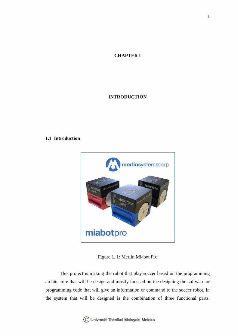
1.1 Introduction
Figure 1. 1: Merlin Miabot Pro
This project is making the robot that play soccer based on the programming
architecture that will be design and mostly focused on the designing the software or
programming code that will give an information or command to the soccer robot. In
the system that will be designed is the combination of three functional parts:
2
programming platform, simulation platform and physical test platform. In the soccer
tournament, each team represented by five robot, a goal keeper, two defender, and
two striker. Basic structure for the robot soccer tournament is using a camera for
detection the ball, other robots and environments. The camera was linked to a
computer and the connections between the computer and the robots are using a
Bluetooth device. It is fully autonomous and incorporates bi-directional Bluetooth
communications, which provides a robust frequency hopping wireless
communications protocol at 2.4GHz. The computer was used to control the robot‟s
motions and actions in current and predicted situations. While the positions of robots
(teammates and opponents) and ball was determined from estimation calculations.
This project needs the knowledge about kinematics analysis. It is used to control the
movement of the soccer robot in term of speed, forward and reverse and turning. All
of the action and movement of the robot is control by a programming language, C++.
This programming will be test by using Simurosot Simulator then the program will
test to the hardware.
1.2 Problem Statement
i. Speed of soccer robot is same as the speed of ball.
ii. The position of goal keeper must be retained when pushed by other robots.
iii. Detection of the opponents, members, goal and ball.
1.3 Objectives
i. To design a program for a shortest path that can be traversed by the robot
faster than the ball.
ii. To create a program for the position of the goal keeper at the right angle.
iii. To apply a calculation in the program to determine the positions of
opponents, members, ball and target.
3
1.4 Scope
i. Scope for this project covers the basic behavior for all robots that can be spin,
move, kick, dash and block. Basic behavior is the command that have given
to each of the players and this is according to the role behavior.
ii. Based on the role behavior of the robot, it is required to make the robot act as
the goal keeper, striker and defender to control a game. Each player will be
programmed according to the distribution function and point. These behavior
help to carry out the duties of players smoothly and according to the
strategies that have plan.
iii. It also covers in kinematic energy that uses to measure the position and angle
of the soccer robot. Analysis for kinematic are focused on position and angle
of a two-wheel robot. The position is known by determination of the
coordinate based on the field and the angle is determined from the reference
angle.
iv. The soccer robot also be programmed by using C++ programming language
to follow the strategy that have been create such as to attack the opponent by
kick the ball to goal, and defending ball from entering home area.
v. The interfacing between the robot and program are using Bluetooth device
where it is integrated in the robot.
4
1.5 Methodology
1.5.1 Methodology of the Project
This project is begin with the literature review which is the study about basic
structure of soccer robot includes camera, Bluetooth, computer and battle area;
programming language based on the processor features and types of robot. Here, the
study is about kinematics analysis (angle and position) and the detection of robots.
Kinematics is affected to estimate the angle, position and decision on the action of
robots while detection is cover positions of all robots and ball. Evolutionary
Programming (EP) for obstacle and boundary avoidance also covers in literature
review.
After that, proceed to design programming where the simple coding is being
tested by the simulator to understand about the movements and the estimation of
angle and position of robot. A simple movement will be created and test with
simulator. Construction of simple movement gradually converted to the movement‟s
that is more complex including basic behavior, role behavior and strategies. As usual,
coding will be tested on the simulator so that each player moves as the programming
command.
The programming that is ready will be checked and troubleshoots. If the robot
does not move as expected or the robots is not followed the strategies, the coding
will be reviewed and studied back. Corrections will be made after the problem had
been identified. Coding will interface to the real robot after being satisfied with the
behavioral players and strategic that shows in the simulator. The programming is
tested to the robots and will be modified if the robot does not move exactly as in the
simulator. Robot movement is differently in the hardware and simulator because of
various factors such as friction and mass of the robots.
5
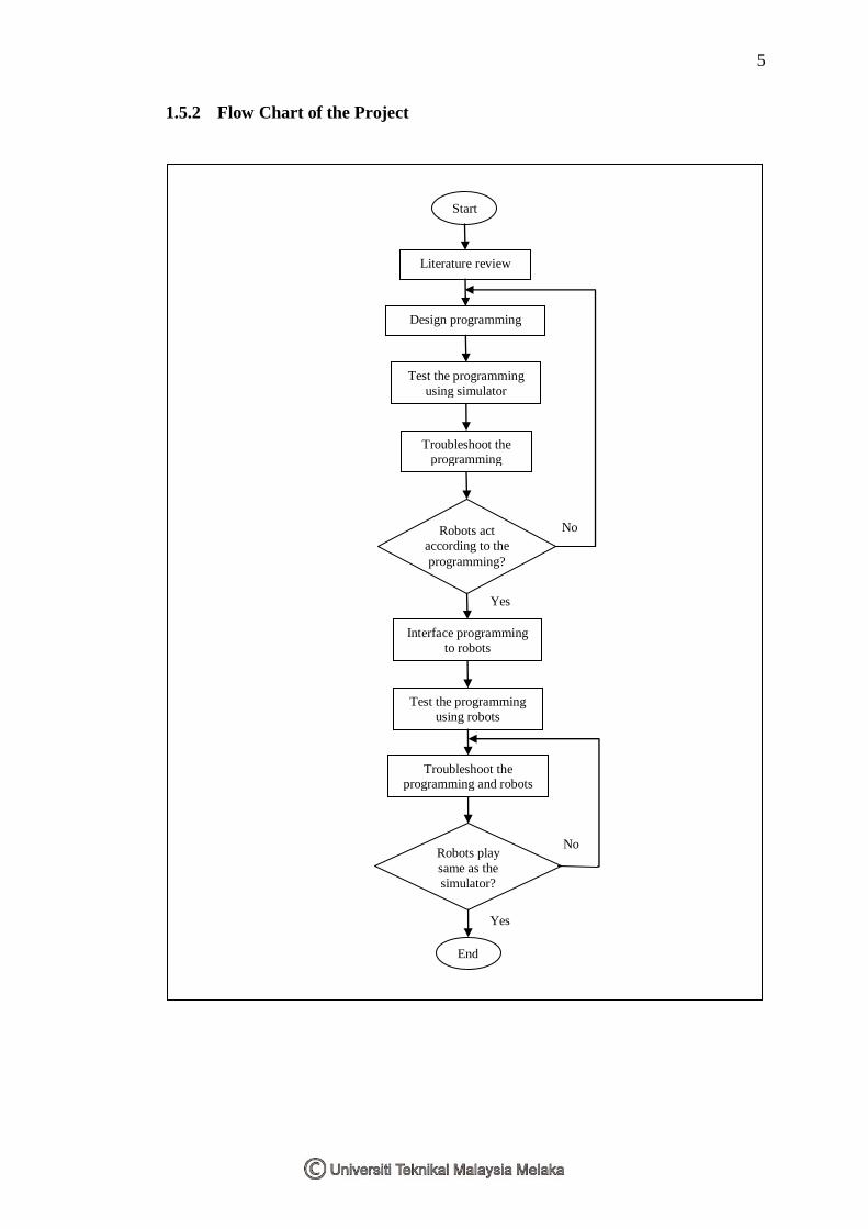
1.5.2 Flow Chart of the Project
Yes
Start
Literature review
Design programming
Test the programming
using simulator
Troubleshoot the programming
Robots act
according to the
programming?
Interface programming
to robots
Test the programming
using robots
Troubleshoot the programming and robots
Robots play
same as the
simulator?
End
No
No
Yes
6
CHAPTER II
LITERATURE REVIEW
2.1 Robot System
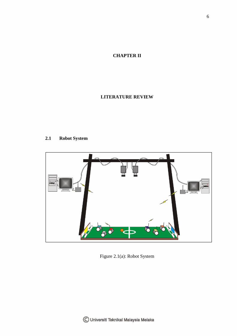
Figure 2.1(a): Robot System
7
As you can see in Figure 2.1(a), this drawing describes the organization of
soccer robot system. On this picture, the intelligence is included in the host
computer, the robots, or both of them. According to where to be embodied for the
intelligence of the system, there can be divided into vision-based soccer robot system
and robot-based soccer robot system.
Vision-based soccer robot system can be divided into remote-brainless soccer
robot system and brain-on-board soccer robot system. As Figure, our soccer robot
system is a remote-brainless soccer robot system, so the host computer has the
intelligence and sends commands to the robots through the Bluetooth
communication. If the robots receive the commands from the host computer, they
only control the behavioral or movement and operation.
For Vision-based soccer robot system, a robot system is a part of robot soccer
system. Figure 2.1(b) shows a diagram of robot system. Robot system consists of
four parts; micro-controller, motor driver, communication, and power unit. The
complete robot is illustrated in Figure 2.1(b). The robot has a circuit board, battery,
motor, and body (including wheels). The circuit board can be separated into the
lower circuit board that has power devices (voltage regulator, motor driver, etc.) and
Bluetooth Communication module and the upper circuit board that has the micro-
controller Atmel ATMega64.