I FILE No. SERVICE MANUAL High-pressureSleamSlerilizer ... · I FILE No. SERVICE MANUAL...
51
I FILE No. SERVICE MANUAL High-pressureSleamSlerilizer Labo Autoclave MODEL NO. MLS-37S1 Ll3781 L Photo: MLS-3751 L INDEX ITEM NAME PLATE • Model No.indication R""N,r:; LABEL +Model No. and rated power supply voltage are indicated here. Model No. Rated Voltage Plug MLS·3751L AC 120V MLS·3751L AC230V MLS·3781L AC230V MLS·3781L AC230V Productcord No. 131699501 131699502 131699401 131699402 1. Safety Precautions in Servicing Work .................................................... ·············1 2. Specifications ...................................................... ·········································2 3. Outside Dimensions ............................... • ........... • ........... • ........................... 3"""4 4. Names of Parts and Operations ...................................................... ··············5-6 5. Construction and Functions ....................................................................... 7 .......... 10 6. Piping Diagram and Wiring Diagram ........... • ........... • ........... • .................. 7. Process Flow and Operations .................................................................. 8. About Various Modes .. · .. · .. · .. · .. · .. · .. · .. · .. · .. · .. · .. · .. · .. · .. · .. · .. ···· .. · .. · .... · .. · .. · .. ·· .. 22 .......... 27 9. Temperature and Pressure Adjustment and Checking .................................... ··28 .......... 32 10. Thermistor Temperature Characteristics / Altitude. Atmospheric Pressure and Boiling Point in Standard Atmosphere················ 33 11. Circuit Diagram ...................................................... ······································34 12. Troubleshooting ...................................................... 13. Disassembling Procedure ............. • ........... • ........... • ........... • ...................... 14. Instruction Manual .. · .. · .. · .. · .. · .. · .. · .. · .. · .. · .. · .. · .. · .. · .. · .. · .. · .. · .. · .. · .. · .... · .. · .. · .. ·· .. 51 .......... 63 15. Parts List ....................................................... • ........... • ...................... 16. Instruction Manual of Works for Optional Parts ··· .. · .. · .. · .. · .. · .. · .. · .. · .... · .. · .. · .. ·· .. 72 .......... 79 REFERENCE No. SM6610004
Transcript of I FILE No. SERVICE MANUAL High-pressureSleamSlerilizer ... · I FILE No. SERVICE MANUAL...

I FILE No.
SERVICE MANUAL High-pressureSleamSlerilizer
Labo Autoclave MODEL NO.
MLS-37S1 Ll3781 L
Photo: MLS-3751 L
INDEX
~-- ITEM NAME PLATE • Model No.indication
R""N,r:; LABEL +Model No. and rated power
supply voltage are indicated here.
Model No. Rated Voltage Plug
MLS·3751L AC 120V
MLS·3751L AC230V
MLS·3781L AC230V
MLS·3781L AC230V
Productcord No. 131699501
131699502
131699401
131699402
1. Safety Precautions in Servicing Work .................................................... ·············1 2. Specifications ...................................................... ·········································2 3. Outside Dimensions ...............................•...........•...........•........................... 3"""4 4. Names of Parts and Operations ...................................................... ··············5-6 5. Construction and Functions ....................................................................... 7 .......... 10 6. Piping Diagram and Wiring Diagram ...........•...........•...........•.................. ·····11~12 7. Process Flow and Operations .................................................................. ··13~21 8. About Various Modes .. · .. · .. · .. · .. · .. · .. · .. · .. · .. · .. · .. · .. · .. · .. · .. · .. ···· .. · .. · .... · .. · .. · .. ·· .. 22 .......... 27 9. Temperature and Pressure Adjustment and Checking .................................... ··28 .......... 32
10. Thermistor Temperature Characteristics / Altitude. Atmospheric Pressure and Boiling Point in Standard Atmosphere················ 33
11. Circuit Diagram ...................................................... ······································34 12. Troubleshooting ...................................................... ································35~44 13. Disassembling Procedure .............•...........•...........•...........•...................... ··45~50 14. Instruction Manual .. · .. · .. · .. · .. · .. · .. · .. · .. · .. · .. · .. · .. · .. · .. · .. · .. · .. · .. · .. · .. · .... · .. · .. · .. ·· .. 51 .......... 63 15. Parts List .......................................................•...........•...................... ··64~71
16. Instruction Manual of Works for Optional Parts ··· .. · .. · .. · .. · .. · .. · .. · .. · .... · .. · .. · .. ·· .. 72 .......... 79
REFERENCE No. SM6610004
macker
Cross-Out

1. Safety Precautions in Servicing WorkPlease read the "Safety Precautions" section carefully to prevent any accidents during service repair and provide a safe product .
• Loss or damage which may result from failing to heed these precautions and degree of their urgency, the precaution have been classified ioto the three categories
&Danger This indication shows the content of the result in the death or serious injure of the operator or other persons.
&Warning This iodicates a potentially hazardous sitoation arisiog from the mishandliog or mis-operation of the unit which, if not avoided, could result io the death orserious iojury of the operator or other persons.
&Caution This iodicates a potentially hazardous sitoation arisiog from the mishandliog or mis-operation of the unit which, if not avoided, may result io mioor iojury of the operator or other persons and property damage .
• The figure sign classifies the contents that must be heeded, and is explaioed. (The followiog sign is an example.)
6. 1bis symbol calls attention to a danger, warning or caution, so please take care.
0 This symbol calls attention to an action which the operator is prohibited from performiog, so take care .
• This symbol calls attention to an action which must be performed or which the operator is iostructed to perform, so tske care.
& Warning Always unplug thc;unit when carrying out inspection or repairs.
• Do not damage or change the power cord . This may lead
C • Always unplug the unit from. the outlet when assembling, 6) to electric shocks or fire.Placing heavy objects on the disassembling. inspecting, or replacing parts.Failure to power cord, heating. or pulling it could result in damage.
PI_pull 0lIl: a observe the above could lead to electric shock. or injury.
Pl""=' fUIlPly phi'
Always return the wiring to its original condition after carrying • Do not splice the power cord, plug it into an extension out inspection or repairs on the unit. cord. or use it with multiple plugs in a single outlet.
& • Tighten the lead holden so that the lead wires do not 6) Failure to observe the above could result:in electric
touch revolving parts, high-temperature parts, shocks, heating '" fue.
high-pressure parts, or edges (sides) of parts. Contact could lead to ma1fimctions, electric shock, or tire.
~ Take sufficient care of electric shocks.
0 • Always replace damaged or worn power cord or lead
• Take sufficient care of electric shocks from the charged wires.Failure to observe the above could result in electric
c.utiowl of 1111 parts '" lead temllnals. shock, beating or tire.
electric: shock
Always use specified parts when repairing.
0 • Parts marked with it are safety parts. These parts are 0 • Confirm that there is no dust and that the plug is secure, inserting it all the way in. Dust or bad connection could
important in maintaining safety. While replacing, always result in electric shock or tire. use the specified parts.
0 • When repajring, always use the part listed on service parts table for the appropriate model and appropriate tools. Also, under no circumstances are modifications to the unit to be carried out. Failun: to observe the above could result in electric shock, heating or fire.
& Caution Beware of burns due to high _perature.
& • Measure the insulation resistance after repe:irs and
@ con:fum that is at least 5M (1 . • Take care, as after operation the chamber door, chamber, A problem in the insulation can lead to electronic
and piping sections are extremely hot. shock.
_,_ Always wear gloves when repejring or inspecting.
& • Confirm that the position of attached parts, condition
& of the wiring, and soldering, or crimp connections are
• Use gloves to avoid injury from. the edge ofmeta11ic normal.An abnormality can lead to heating, :fire or surface. electric shock.
-1-

2. Specifications
Product Designation Labo Autoclave (High-pressure Steam Sterilizer)
Model Designation MlS-3751/3751 l MlS-3781/3781l
120V unit: 120VAC ( 50/60Hz ), 15.BA 220V unit: 220VAC ( 50/60Hz), lB.2A Power supply 220V unit: 220VAC (50/60Hz), 9.1A 230V unit: 230VAC (50/60Hz), 17.4A
230V unit: 230VAC ( 50/60Hz ), B.7 A
Power Consumption 1.9kW ( 120V only), 2kW 4kW
External Dimensions 47B(W) x 632(D) x 74B(H) mm 47B(W) x 632(D) x 965(H) mm
Weight Approx. 61 kg Approx. 71 kg
Internal Capacity 57l BOl
Effective Internal Capacity 50l 75l
Chamber Dimensions 370 (dia.) x 415(D) 370 (dia.) x630(D)
(Effective depth including cover: 463) mm (Effective depth including cover: 6BB) mm
Chamber Material SUS304 (Austenitic stainless steel)
Sterilization Temperature 115°C - 135°C
Melting Temperature 60°C - 114°C
Heat-retention Temperature 45°C - 60°C
Thermometer Thermistor, digital display (25°C - 141°C)
Safety Valve Releasing Pressure 240kPa (34.Bpsi, 2.4bar)
Pressure Gauge Range -0.1 - 0.4 MPa
Sterilization 1 min. - 5 hrs.
Melting 1 min. - 5 hrs. Timer
Heat-retent 72 hrs. fixed
Timer 1 week (Designation: Year, month, day, hour and minute)
Exhaust Tank 2 liter Polyethylene tank
Warning and Safety Functions Pressure safety valve, overheat prevention device, dry-scorch prevention, cover interlock, excessive pressure prevention, earth leakage breaker
Sound Pressure level Max. 75dB (A)
Stainless steel baskets - Large: 1, small: 1 Stainless steel baskets - Large: 2, small: 1
Accessories Drain hose: 1
Exhaust tank (1), exhaust tank at rear side (1), tank mounting bracket (1) and tip-resistant metals (2)
Object temperature sensor, external temperature sensor, printer, stainless steel basket (large), stainless steel basket (small),
Optional Accessories punching basket, sterilization can
·Please consult us about the model number, price, delivery date, etc. including other optional accessories than shown as above .
• The specifications may be subject to change for improvement without prior notice.
-2-

I Front Side I
478
75
~ t-
l ~J ~
\
~ - c-
D ~
r- '-
100
II =W 100
r~ I
:a 1 ~ l::
1159
420
678
Lateral Side I
<1~ 1
\ 1
1 632 I 1
1
\ I
I 1
o I. = === = === = === ===
ill · ;..c:1 1c::::::J1 · ---,
= . = = = . · . . II} ~ g
426 71 66 607
673 689
766
~ 9
~ '" "" ""
• eN -..j 0'1 ...... r o c:: en c: CD g 3 CD :::J C/I c)" :::J C/I
~
3 3 ~
o c ...... en 0.. CD
o 3 CD :::J en o :::J en

I Front Side I
75
..--\
D
Lateral Side I
-4~ 1;-1
632 I I I
• ['II = === = === = === === 1!1 ·
1c:::::J1 ·
r""
'---..J
~9 = . = = = . · . .
~~ ~ 426 171 66
607 673 689 766
<=> ~
o.n ..., ...,
• w -..j 00 ...... r o c:: !if c: CD g 3 CD ::::I CJl c)' ::::I CJl

4. Names of Parts and Operations
Rear.lde » ~" = '8
~ ~ ~
~~=~~2r~~~~pno~'~U~~~~IW~~~+-______________________ +-__ ~ ~ Steam is discharged through this port if pressure in the chamber rises abnonnally. ••• • Control panel •
MOVIIbie handl. • Used for unlocking the cover. • The covar can be unlock8d by ../ - 1- -..... ____ -.
Exhaust tank,---J~ on the rear side
pressing this handle down and ~ I "
pulling toward you. ~j:-l::::;;:;;;::';'7V~/t 11C;;;;;~;;;;;C~0YII~r;;;;;;;;,,"~ r---=c-::::-----,I ~r-~~ ~ C' 0 -l / ~ CQllllllr to shut the chamber tight.
~ It is lined with silicon rubber Handle pecking.
Use for opening/closing the ~
cover. II @ G~p
P ..... UNa.ua. Indicates the pressure inside the chamber.
mn ~ I~! ... L rJ oH)~-~c-::~r'lch ~
Exhaust tank ~ - If ., ...
f-Co-nd-e-'n."e"."'."'tea=m"e"m"';H'-ed--+-J.~.l;"",J] J • ~v R""""" thO """,r to ",nnee! th. from the chamber. _ . V optional printer to the product.
-•• -...... JI---C~~ Tankcua Encases the exhaust tank.
Exhau.thOH Sends steam and air in the chamber to the exhaust tank.
" : ~J-</
C==~~~==~--Rtfr~4
• .
'Ii C •• tar
Exhu.t valve Manually opening/cloeing valve uaed for draining heating water from Ihe Ohamber.
Drain outlet
Packing. '\ ~.~! .. ! Hose in tank Ii. ~
f-::-------'====----c-+---t+,,"f+-; .f! ~ Converts steam discharged \ p from the chamber Into water. ~
Heating water III drained from the Ohamber Ihrough this outlet. Connecl: the included drain hoee to drain heating water.
-5-

Control panel
II Cover lock lamp
Indica\N hi _ tim., rem .... ing Indica\N hi nlu. of the currvnt U~ "" wIIIIn opI~on.aart. tm., llerilizdon qd8, exhawt proce. with • flitbring bar. with .. COlIer locked. !D, cautionary m~ .rror mMIIIIgIIl, dIIte IIIId voice ~id.
,bulla" . Mltting.
WhIll1 the optlona' obfect Indicates Iha _18cIed lblrilizRliDn
tlImperlltUre .,".or I, In.lalled
I cycle with • Iii limp. and thl' object templll'&lure button '- preMed, the I~ IIglU
Indica\N hi currtlnt ...,.ratu ... , up and the llerlllzatlon tllTlllr II controlled by !he ~rature of
llerilizdon Nt I8mpendur., ,lamp
obfMD to be ..... lIzed. mIIlting MI temperature, IIIhBUII: IIIIrling templill1llUre, date, hourimllUlM and voice guide LIghts up wh8l'l the chamber '-MIttIng. Intemally undlr prusure.
Thlllllmp Ilghtl up whln thll button '- pl'UMd.
I
. IBBI fo : v-~ ~ BAtI'tD
... IBBB lo, • ~- ~~ ,-
~~ ~ '''; .:-:
Timer I s_ thallma untiliha liar! of ' bUtton Model No. r operation.
Indates changa 01 MIllIngs and MIllIngs 01 CUlTlll'lt op8l'llllDn on Stop I II1II digital dilplays'lnd II.
Stope operdon and cancelli lJMd Ibr IlItIIng and dlRnglng the tilnllr Htting. and hINd-l'lMntion. sIIIr1llz1lllon tempM'atul1l, sItIr1llz1lllon 1m., nwllng I8mpllllLlure, rnellng Ima, hINt-
lJMd In engage the cooling modi! .... ntion tamperw.tul'8, 1IIChI.u.t Start button I8mperalure, sIIIrt timer and clnlng IIXhaulilng. ..,.ust rate. StarIti opaIW.tlon and IIm .. _
operation.
Time I
Current Ilmlli5 DlICUld on SIIIIIca .ny 013 progran-.1IIId <4-
clgital dllplay I. cydIII (toIII1 121111111c101ll).
-6-

5. Construction and Functions
_Names of parts and functions are common to Series 3751 U3781 L. The photo shows Model MLS-3781 L. . Part name may be I I list when you place an order.
1
2
3
4 7
-,
No. Part Name Function 1 Pressure gauge Bourdon tube pressure gauge for displaying pressure in the chamber 2 Tank Tank for exhausting air in the chamber 3 Front panel Front side frame constituting the appearance of the temperature
detector 4 Richt side Danel Constitutina the richt side appearance of the unit cover 5 Side panel. R Right side frame constituting the appearance of the unit 6 Left side panel Constitutin the left side appearance of the unit cover 7 Side panel, L Left side frame constituting the appearance of the unit 8 Safety valve cover Plate to block steam blOW'ing out when the safety valve is actuated 9 Back side Danel Richt side frame constitutina the appearance of the unit
10 Handle, frame Handle for moving the unit
-7-

1
13
12
14
2
15
11
16
17
Right Side
No. Part Name Function 11 Valve assembly, 1/28 Manual valve for draining the water for heating the chamber inside 12 Fan motor Air blowin~ fan for coolina the chamber 13 Chamber set Chamber to seal UD steam and Derform sterilization 14 Chassis Base plate to fIX the arrangement component parts and support
them 15 Caster Caster for moving the unit. 4 casters are used. Equipped with lock
function 16 Pressure sensor Semiconductor sensor for detecting the pressure in the chamber 17 Thermistor assembly Sensor for temperature detection
-8-

18
19
II
-9-
20
21
22
23
24
25
26 (The operational unit body is in this unit.)
i i

27
28
No. Part Name Function 27 Packina, chamber Fitted to the lid by sealine oackina for sealing the chamber 28 Lid set, chamber Chamber see line lid which can be ooened and closed Quicklv 29 Heater cover stand on which sterilization object to be put In the chamber Is placed 30 Packing, panel Packing to seal the gab between the dlamber and the panel 31 Sheathed heater set Heat source heater to generate sterilizing steam 32 Lock shaft. Part for locking to seal and fix the chamber and the cover 33 Panel Panel to vertically oartition the chamber and the cover 34 Circuit breaker Electric pert to shut down the power supply circuit in case of an
over-current in the unit
-10 -

6. Piping Diagram and Wiring Diagram
• Piping Diagram
HOSE EXHAUST
I JOIN'[ L R1I4 x G1I4 FLARED SAFETY VALVE AS~ (560)
r::V~ PIPE AS~ SAFETY VAlVE
HOSE TANK / \
.~ JOINT, ORIFICE (\)1.8
HEATER AS~
ELECTROMAGNETIC VALVE NC
PIPE, EXHAUST
PIPE ASSf, PIPE COOLING rs PRESSURE GAUGE
'" SENSOR, PRSSURE NSK -BAOI OB -092
HOSE, IN TANK
PRESSUR GAUGE, 350P PIPE ASSf, PRESSURE SENSOR
JOINT T VACUUM
JOINT T CHAMBER TANK, MLS -3781
VALVE, VC12B1-F VALVE ASSY DRAIN 3781
PIPE ASSY,FREX .l250
- 11 -

• Wiring Diagram
51: Rl 81: OJ
16 C 51:R2 81: Q2 3 1
aRCUIT 3 1 BREAKER
10 C 51:Rl L,J 81 :Ql I
11iERMOSTAT (MANUAL RE1IIRN)
= P ---D
lIiERMO
HEATER
J HEATER
DD DD
CN10l D DS -PCB OS
CN103rl~~= SClENDID
CN201 Il=~SPPCB ,,JL,',f)"D7S1CE P,C.O. Am, DISPlAY 3781 U=:::J L----D ltj I n--------n1
PIISSURE LOCK SHMT ~SP
S"""R cd SW un n ;; lli®l:'":.ECT TEMP Q 81'~' ~ e! SENSOR
,--------~ I PS 51:' IDl'TIDNJ -
3 14 ~13 J.d 13 r!d 1 gmj LCNlLJ LOOfiJ ~ ~ 3 mt 1
EXHAUST VALVE 51:W 0--0 n-81: V CN9
HANDLE LOCK SOLENOID
C-UD-:-~
2 NC , NC §] INC, '=5 ~
, 3
~ OPllONAL PRINTIR CONNECllON 1 5 [iiiii] WR
4Wli
~"\ ~n F.~137~81~~~~tf~"l" , B
I'~ RELAY ~ -,-----H CN3 I 7 5 ~ 8 , 2
~l9~f+tirB:3t1fCN7 auo32 B.<m11Y FOR COCK
U ~1
A3781CE ~ ~ TERM~L
1378ICE I I BLOCK P.C.B.ASSY ,CONTROL CE
~H 1 r s g I ~.-----,' 1 5 '~-
"---_ L --=~ +I:\TlI--t= L=h Lilllill ~II ICN5
I '1Qj!J 3 ,
MU'ER ~ ,~+t~f2~~~~;;~~tt"~~~'·~·IT17~"~=r5F~3n;'C~E-rIl-----~ ~vn 22OY: 8220 3781
llIANSFORMER D- "", •• ,., ~c::Jl ~ ~ ~-~~
., ~SA ~--~ COOLING FAN 11OV: 03751 CE FQ 11OV,13OV: N 3781 CE
POWER TRANSFORMER
I
l'1!.N:Bl2G 3751 22OY: IWG 3781 nov: Bl3Q 3781
I
51: P.C.8,ASSY, EM0l51 CE 81: P.C.8,ASSY, EMeJ781 CE
* Note) 51 in the figure shows MLS-3751 L, and 81 shows MLS-3781 L
- 12-
2A
37S1L(12OV),3781L(23OV ENTElA): Cl7811N1RA one! MOOEl5: (3781 CE

7. Process Flow and Operations
(OOperations and displays
I Operations and Process! Digital Display I Digital Display II
Turn ON the power. Boiling point setting temperature is Bar display "- - -" is displayed for the displayed for the first 4 sec. Thereafter,
f--first 4 sec. Thereafter, the display
the display changes to stand-by display. changes to stand-by display.
STAND-BY ~ Setting temperature is displayed.
f--Setting time and cycle are displayed
However, The temperature in the alternately. However, the water heating
I chamber is displayed by pressing the temperature is displayed by pressing the " ... " + "T" buttons at the same time. If " ..... + " ..... buttons at the same time. If
Put sterilizing object the temperature is lower than 25"C, "La" the temperature is lower than 25"C, "La" and close the cover. is disolaved. is disolaved.
I Press the start
button.
"COVER LOCK " lights up and the process monitors flicker.
HEAT f-- Temparature in the chamber is f--Nothing is displayed. However, the water heating temperature is displayed by pressing the ~ ... ~ + " ....
displayed. However, if the temperature buttons at the same tima. If the temperature is lower is lower than 25"C, "La" is displayed. than 25"C. ·Lo~ is displayed.
STERI (MELT ) Temperature in the chamber is Kemalnlng smnllzatlon orne IS CISPISyeC. However,
r-- displayed. r-- the water heating temperature is displayed by pressing the""'~ + ..... ~ buttons at the same time.
I EXHAUST
Temperature in the chamber is NOlmng IS cisplaye~. nowever, me WSIer eaung
r-- displayed. r-- temperature is displayed by pressing the" ..... + .. ..... buttons at the same time.
1""---------_._._._._._._._._._._._._._._._._._._._._._._._._._._._._._._._._._._._._._._._._._._._._._._._._._----
Elapsed keep-warm time is displayed_ However, the
Temperature in the chamber is water heating temperature is displayed by pressing KEEP WARM f-- f-- the tt ... w + ~ ... u buttons at the same time_ By pressing
displayed. the ttRESERV" + ~ .... at the same Ume, the elapsed keep-warm time is displayed in minute_
STERI/KEEP WARM MELT/KEEP WARM ---------- --------------------------------------------------------------------------------------------------------
Bar display" " is displayed. However, the Temperature in the chamber is water heating temperature is displayed by
COMPLETE r-- displayed. However, if the temperature r-- pressing the .... " + MT" buttons at the same
is lower than 25"C, "La" is displayed. time. If the temperature is lower than 25"C, "Le" is displayed.
I "COVER LOCK "goes out and the all process monitors light up and the "COMPLETE"
I flickers. pen me cover ana
take out sterilized obiectCs). Setting temperature is displayed_ However,
Setting time and cycle are displayed
I the temperature in the chamber is displayed alternately_ However, the water heating
~ by pressing the ... " + MT" buttons at the
temperature is displayed by pressing the ... D +
STAND-BY same time. If the temperature is lower than f-- "T- buttons at the same time_ If the
25"C, "Lo" is displayed. temperature is lower than 25"C, "Lo· is displayed.
- 13-

• Liqyid Sterilization (]-1 1-2 and 1-3)
~ ~ ~ • ~ ~ ~
"",- Heatilll Airpurp= Heatilll Sterilization Coolilll Corq,letion
powLIW. Lid !ION 'I 'I
, 'I
, , 'I "". -- .... Boiling point R""chi..- Udapen
IS.-- '" ... -. SteriliZlltionutl:imll
Te
Sterilization settinlte~ - ------ --- ------f-----Imin.
~ OFF at boiling
Exhaustsettinlte~. - f------- --- ------r...J!.Ol!!!;+7'C __ ----------=n A ..... _ ---------t BoilinlPoint- ------ --- ------f----- --- ---------
65"C- ------ --- --- - f----- --- -----------------1-_ ,
~ i .' --------- .... ---__ i ,," --, ." ... " .............. " ;,
0""'"- r-. ~f----- --- -----------------~~
HeaterTriack •• • ••• Heater relay
Exhault valve (NO
Handesolenoid (Unlocked bypower-ON)
F~
..., ShortBeep ~ .. ~.,(1";m •• Speaker
~ ~" ... ;
Dilital c:isplay 1 ... ,- I" Temp. in Chamber (Displayed lit hillher than 25'C)
Dilital c:isplay 2 "',- Rllmainilll starilizatian
i ,~
I ! !
Processmonitor H..ti"lll H .. ting2 Sterilization
"" Exh.uat 1 ~ Corq,Iet;ion
~
"',- ,
... ,-"',- >
-1'0) .....-"tI ., o n CD 1/1 1/1 -to 0' :E n :::r \II ., ....

Temp.
Press.
nStorilization/Koep Warm (2-1 2-2 and 2-3)
1 'I Lid OIOM Start
• Heatin
'I Boilinl point
• • Heatin ,
'I Reaohinl set. temp.
• • Sterilization Cooli Compllftion , , ,
'I Lid open
Ster1IIZ11tloneettlme
Sterilization settingtemp. --- --------------- --------------- ----------------
== ••••••••••••••••••••••••••••••••••••. ~:~~ ••••••••••••••••••••• ·.~\~==:7~'~h~,:.===!1-__ _ --i"---------I-- i
/ ----~ ~~ ~ ~ "" .... ;........... i ,~
ot.I'. --1------ __ .+ __ ._.L --------------- ----------- ------------------------ ------------------i----"r-t-----'--+---1 HeaterTriack
Heater relay
Exhaust valve (NO)
Handesolenoid (Unlocked bypower-ON)
Fon
•• •••• i ••••
Stand-by ,
___________ ~ __ .k_.'~~~~~~.i~~~i:~~~·~~~~~~~~~~~~~~~~~ .. ~~~~~~~ Digital display 1 I ... ---... -"-... ...;.r=--;--'TV'-----"T"-----"T"---"T"--T ... ...;.-. _;"_"'""" __ ._'~(D_; .. i-' ... ;...d_"_h .. ;;..._'_"_._"_25""..;.) ...,-...,--------...,----~ .. T .... ----..;.-~"
k" i"(1'''m~ It Stand-by >
Digital diSPlay21 ..... __ ... ...;."~ ... ...;.r-_"l
I Process monitor Heatl1'll'2
. nemaininl sterilization ,,-Starlllzation Exhaust 1
Keep-wann elapsed Stand-by > time
I" KellJlwann Comph!ll:lon

• Melting/Keep Warm (3-1 3 - 2 and 3-3> When the mettlna: temp .... ture II Ht at hl&her than l05"C, flXhault. aperatlan II performed for 8 mlm..t boIllna: pHrt + 5"C .fter heatlna:.
• • • ""- He.tinl Meltinl
1 '1 , m,.--T.
p~
pJr_. Lid clo.. Start ~lhina: ss.-- '" '" ....
Meltinl Ht time
Meltingsettingtemp. -- ---------------- ------- ----------------
Keep-wannsettingtime --- --------------- -------- ---_.- ----_._- ---_._-----_._-----_._-----_._---
". r----------0 .... -- -------- ............... J-.-- ---_._-----_._-----_._-----_._---
Hem:erTrieck •••••• Heater relay
Exhaust valve (NO)
Handesolenoid (Unlocked bypower-ON)
Fon
.... ShortB.ep
Speaker .~ • ."dBo,P
• Coolinl ,
~ "', -----------
~ ....
• • "',,- Completion , 'I
Lid open
72 hra.
------_._-----_._-----_._-- -r-
r------- --•••••
~ .... lieP(lOtim .. >
Digital display 1 ""- T.....,. in Chaniler (Displayed at hilher then 25"C)
Digital display2 ""- RemIIininl meltina: time Koap-warrn elapsed time
Proc8samonitor I HtNrtina:l W Meltinl Elchauat 1 It "'''- W Completion
• ""- ,
""- >
""- >

.Instrument Sterilization (4=1 4-2 and 4=3)
• • • • • • -- Heating Air pu .... H..ti Sterilization ~Ietion
T."" -- .,L lJd~ :!.. 'I , 'I
, Boiling point Reaohing
, 'I
Udopen Press. -- a< ... -. Sterilization_time
Sterilizationsettingtemp. -- ---------------- ------- ---------------- --------------- ---------.,.,l-i ________ _\.... OFF::ilinr /i
point +1"C :
BoilinSpont--- --------------- --------
)--------- .... /' ....
~ : " / ' .... OM., -+---+-+--,--£'. ~~~. ;:--+---------------..... "'!----+---.-I
HeaterTriack
Heater relay
Exhaust valve (NC)
Handesolenoid (Unlocked bypower-ON)
Speaker
•• : ....
~ .. , ~.ep('Otim",
• -- ,
Digital display 1 1'--~-;;;;;~-.;;;,r--'II'----...,-----...,--~T.~m~'.,;;;"~c~ .. ~""~w~(D~;-;;;;~.~d~.~'~h;;"',W~"";;;;"~"~"~};..._ ... -----T"----,/T ....... ---;;;;;~-~--.>" I
~Ietion
-- > Digital display 2 St:.nd-by k momalnlna: sten IlAtion 1'-----;-1- : ,-.... ,---_.1....-""''',',.... .... Heatinl' '] Heatinl 2 ~ Sterilization '] Processmonitor Exhaust , Exhaust 2

(3)Descriptions of process operation G)Set the exhaust tank to the unit.
Fill the exhaust tank with water up to the "LOW" level and set the tank to the unit.
~Turn "ION" the power switch. For the first 4 sec., the boiling point setting temperatura is displayed on the IDigital Display II and the bar display "- - -" appears on the IDigital Display III ' and then the set temperature, set time or the cycle is displayed. Press down the handlij and pull the Imovable handleltoward you to open the cover. Fill the chamber with water until the end of the water level metal of the heater cover is immersed in the water. Put object(s) to be sterilized in the attached stainless-steel basket, set it in the chamber and close the cover.
@Heating process (Process monitor lamp: "Heating" flickers.) After checking the detail of the cycle and settings, press the ISTART buttonl. Then, "Beep Beep" sound is heard and the power to the ~terilization heate~ is turned ON to heat the heating water and generate steam. At this time, the air in the chamber is driven out by steam. The steam at that time is discharged into the exhaust tank where it is condensed to water. Also, excess steam which could not be condensed enough flows into the back side exhaust tank at the back side of the unit. After the completion of air exhausting process, closing of the c-x-;h:-:a-us-:-;t-v-::a~lvCle fills the chamber with steam and raises the pressure. After starting, the COVER LOCK lam lights up and the cover can not be opened due to interlock function.
@Sterilization process (Process monitor lamp: "Sterilization" flickers.) When the temperature in the chamber reaches the sterilization temperature, the Isterilization time~ starts working. During sterilization, the tern erature in the chamber is detected by the lateral thermistor (THI) and the power supply to the sterilization heate is controlled by microcomputer. The temperature can be set every i'C between 115'C and 135'C. When the set sterilization time elapses, the sterilization process ends and goes to the next exhaust process.
@Melting process (Process monitor lamp: "Melting" flickers.) This process is for melting culture medium, etc. The temperature in the chamber is detected by the lateral thermistor (TH I) and the power supply to the ~terilization heate~ is controlled by microcomputer. The temperature can be set every I'C between 60·C and 114"C.
@Exhaust process (Process monitor lamp: "Exhaust" flickers.) <For INSUMENT STERI> By shutting down the power supply to the ~terilization heate~ and opening the lexhaust valvij, steam in the chamber is discharged into the exhaust tank to perform cooling. This process is to be performed when the sterilization object is instrument, etc. <For other than INSUMENT STERI> Shut down the power supply to the ~terilization heate~ and keep the lexhaust valve ~Iosed so that the temperature in the chamber is cooled naturally. When the tern erature in the chamber lowers down to the preset exhaust temperature (initial value or boiling pint), th exhaust valv opens. This process is performed when the sterilization object is liquid such as culture medium, etc. The sterilization object is prevented from spilling out due to burst boiling.
(l)Keep-warm process (Process monitor lamp: "Keep Work" flickers.) The temperature of sterilization object such as melted culture medium or sterilized culture medium can be set and maintained every I·C between 45"C and 60·C and the sterilization object can be kept warm for 72 hours. (The keep-warm process can be completed by pressing the !lTOP buttonl.) The temperature in the chamber is detected by the lateral thermistor (TH I) and the power supply to the Isterilization heate~ is controlled by microcomputer.
@Completion process <LIQUID STERI cycle/INSTRUMENT STERI cycle> (Process monitor lamp: "Completion" flickers.) When the temperature in the chamber lowers down to a certain level, the buzzer sound "Beep" is issued ten times, and the bar display"- - -" appears on the IDigital Display III to inform the completion of operation. <Sterilization/Keep-warm cycle· Melting/Keep-warm cycle> (Process monitor lamp: "Completion" flickers.) After the completion of keep-warm cycle, the buzzer sound "Beep" is issued ten times, and the bar display "- - -" appears on thel Digital Display III to inform the completion of operation.
- 18-

(4)Descriptions of safety device actuation
eCaution sions
Caution Sian Disolav Condition Cause/Checkina/Remedv Lid Cover is not closed comDletelv. Press down the handle by force.
When the START button is pressed, the Press the START button after the temperature in Hot temperature in the chamber is higher than the the chamber has lowered.
nreset temnerature. Due to bending or clogging of the exhaust hose, Pull put the exhaust tank and correct
HOSE abnormal pressure was detected more than 7 the bending of hose. Check the exhaust circun times durin" heatin" for anv cloaaino. (j)Operation is started without opening the cover (j)()nce open the cover and start the operation.
door immediately after power-ON. ®Replace the lock shaft detection switch. ®Trouble with the lock shaft detection switch
eError sians
Enror Sian Disolav Condition Cause/CheckinaiRemedv El Lateral thermistor (TH1) Lower than 21"C Smin. after the bottom ' Check the thermistor (TH1).
Open thermistor becomes 90·C. ' Check the thermistor (TH1) connector. E2 Bottom thermistor (TH3) Lower than 21'C for 2min. after starting , Check the thermistor (TH3).
Open and 2 min elapsing. ' Check the thermistor (TH3) connector. E3 Lateral thermistor (TH1) Higher than 139'C ' Check the thermistor (TH1).
Abnormal temp. ' Check the Triack. E4 Object temp. sensor Higher than 140'C ' Check the thermistor (TH2).
(TH2) Abnormal temp. ' Check whether or not the tip of the object temp. sensor lips down into the heater unit.
E5 Bottom thermistor (TH3) • Higher than 110'C in heating I, • Check the thermistor (TH3). Abnonnal tamp keep-warm process. • Check whether or not the exhaust port
• Higher than 120'C in heating 2, is blocked with sterilization object. exhaust process. • Isn't the amount of heating water
• Higher than 140'C in heating 3, heating reduced and isn't the chamber is 4, sterilization process. heated wnhout water?
• Or, higher than set temp.+30·C • Check for leakage of steam or water. E6 Unlocking of the movable The detection switch is not turned OFF • Doesn't the lock pin catch?
handle is impossible. even when the power supply to the • Check the cover swoch. solenoid is turned ON and the solenoid is unlocked.
E7 Locking of the movable • The detection switch is not turned ON • Doesn't the lock pin catch? handle' cover is even when the power supply to the • Check the cover swnch. impossible. solenoid is turned OFF and the • Check the lock shaft switch.
solenoid is locked. • Lid detection switch is turned OFF
during operation. • Lock shaft detection switch is turned
OFF durina oDeration. E8 Abnormally high • Pressure in the chamber is higher than • Sterilization object which makes the
pressure about O.33MPa. exhaust difficult. • Pressure in the chamber is O.04MPa • Exhaust circuit is clogged.
higher than the saturated steam • Exhaust port is blocked with the pressure in the temperature of the sterilization bag. lateral thermistor at heating 4 and sterilization processes.
• Deep sterilization can is used.
E9 Low pressure • Pressure in the chamber is O.04MPa • Shortage of heating water. lower than the saturated steam • Exhaust circuit is blocked. pressure in the temperature of the lateral thermistor at heating 3 ,heating 4 and sterilization processes.
El0 EEPROM communication Nothing can be read out or written from • Check and replace PCB. error or on EEPROM.
- 19-

-Hard limiter When the temperature in the chamber which was detected by the lateral thermistor (TH1) rises to higher than 140'C, the Triack and the relay control circuit is controlled directly by TH1 temperature detection and the power supply to the heater is shut down. This circuit is not controlled via micro-computer and it is reset automatically when the temperature lowers. (Actuated in all processes.)
- Pressure safety valve This valve opens to exhaust steam in the chamber and prevent abnormal pressure rise so that the pressure in the chamber should not exceed O.25MPa.
(5) Functions of specific parts and cautions
<Deaver interlock This is a safety device to prevent the user from opening the cover by mistake when the pressure in the chamber is higher than the atmospheric pressure. In order to check seating tightness between the lid and the chamber, micro-switches are mounted to their lock shafts. Also, 1 micro-switch is mounted for detection of the position of the solenoid for the movable handle lock and 2 micro-switches to the lid for detection of lid open/close status.
-When the cover is closed, the 2 micro-switches mounted to the lock shaft and the lid detects that the solenoid is in the specified position, and "Beep" sound is issued and the operation turns to stand-by status.
- When the START button is pressed, the live solenoid becomes non-live and the end of the solenoid enters the hole of the movable handle. By so doing, the movable handle is fixed and at the same time, the micro-switch is pushed by the end of the solenoid and the position of solenoid is detected to start the operation.
(Cautions) If the START button is pressed with the cover lock being incomplete, the caution sign "Lid'" appears on the digital display of the control panel and the buzzer sounds. This is to inform that the lid is not closed up to the normal position. Therefore, the cover handle must be pushed down until the buzzer sound "Short Beep" is heard .
• When the "Lid'" display appears, the following causes are taken account. • Handle is not pushed down completely.
Since the temperature in the chamber is high, repulsive force (force to open the lid) of the chamber lid packing is too strong to push down the handle .
• The chamber lid packing is removed and the lid bites a part of it.
®About the "door" display Lock shaft is closed when the cover is open (detection switch "ON"), the lock shaft opens once as the cover closes (detection switch "OFF"), and it closes again (detection switch "ON") when the cover closes. In order to detect adherence to ON of the lock shaft switch, it is checked by microcomputer that the lock shaft opens and then closes (detection switch turns OFF and ON.), and if it was not detected that the switch is OFF, "door" is displayed.
(Cautions) If the START button is pressed without opening the lid immediately after the power is turned ON, the "door" display appears, but this is not due to any trouble. Close the cover once and then press the START button to start the operation.
- 20-
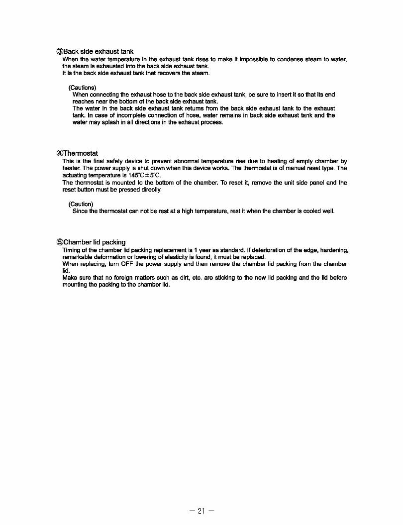
@Back side exhaust tank When the water temperature in the exhaust lank rises to make it impossible to condense steam to water, the steam is exhausted into the back side exhaust lank. It is the back side exhaust lank that recovers the steam.
(Cautions) When connecting the exhaust hose to the back side exhaust lank, be sure to insert it so that its end reaches near the bottom of the back side exhaust lank. The water in the back side exhaust lank returns from the back side exhaust lank to the exhaust lank. In case of incomplete connection of hose, water remains in back side exhaust lank and the water may splash in all directions in the exhaust process.
@Thermostat This is the final safety device to prevent abnormal temperature rise due to heating of empty chamber by heater. The power supply is shut down when this device works. The thermoslat is of manual reset type. The actuating temperature is 145°C±5°C. The thermoslat is mounted to the bottom of the chamber. To reset it, remove the unit side panel and the reset button must be pressed directly.
(Caution) Since the thermoslat can not be rest at a high temperature, rest it when the chamber is cooled well.
@Chamber lid packing Timing of the chamber lid packing replacement is 1 year as slandard. If deterioration of the edge, hardening, remarkable deformation or lowering of elasticity is found, it must be replaced. When replacing, tum OFF the power supply and then remove the chamber lid packing from the chamber lid. Make sure that no foreign matters such as dirt, etc. are sticking to the new lid packing and the lid before mounting the packing to the chamber lid.
-21-

8. About Various Modes
Models MLS-3751 U3781 L are equipped with the following modes. As for the detail, refer to the pages of respective modes.
Setting mode: Display of processing frequency, history of errors, etc. and settings. etc. Test mode: Display of temperature and pressure in the chamber, adjustment of thermistors,
pressure sensors, etc. Demonstration mode: Display of actual operation status and demonstration of operation, etc.
-How to enter into the setting mode 1. Tum ON the power switch. 2. When the ".A. "+ "SET/CONFIRM" buttons are pressed for
about 2 sec. while pressing the "START" button, "Short Beep x 3" sound is heard and at the same time the decimal point on the Digital Display I flickers. (See the right figure.)
3. After the status has become such as in 2, when the "START" button is pressed within 5 sec. while pressing the ".A."+ "T" buttons, "Beep· sound is heard, and at the same time the mode becomes the setting mode and model name and speech language are displayed.
-How to cancel the setting mode
flicker
"c sterilization
1- 1
When the power switch is turned OFF, the setting mode is cancelled. Or, when the "STOP" button is pressed to enter into the test mode and the operation in the "How to cancel the test mode· is performed, the setting mode reset to the normal mode.
-How to enter into the test mode A. In stand-by display
Enter into the setting mode according to the procedure in the "How to enter into the setting mode" and press the "STOP" button. Then, "Beep" sound is heard and at the same the mode changes to the test mode. The difference from the normal mode is such that the decimal point on the Digital Display I lights up. (See the right figure.)
B. In operation When the procedure in the "How to enter into the setting mode" is performed during operation, "Beep· sound is heard and at the same time the mode changes to the test mode.
-How to cancel the test mode
Flicker
Light-up Sterilization
I 51e .lizati~ 12 1
0:2'1
"c
Time
When the power switch is turned OFF, the test mode is cancelled. Or, when the "START" button is pressed for about 2 sac. while pressing the ".A."+ "SET/CONFIRM" buttons, "Short Beep X3" sound is heard and at the same time the test mode returns to the normal mode.
-How to enter into the demonstration mode 1. Turn ON the power switch. 2. Start the reservation operation. 3. When the "Cycle selection" + "STOP" buttons is pressed within 5 sec. after starting the reservation
operation, "Beep Beep Beep· sound is heard and at the same time the stand-by is displayed and the mode changes to the demonstration mode.
-How to cancel the demonstration mode When the power switch is tumed OFF, the demonstration mode is cancelled.
- 22-

(1)About the setting mode In the selling mode, product infonmation, factory setting, processing frequency, history of errors, boiling point setting, exhaust setting, address, option I, option 2 and channel display frequency setting and checking can be perfonmed.
II Mode
(j)Product infonmation
I~FactOry setting
@Processing frequency
I@HistOry of errors
@Boiling point setting
I@AirpUrge
IClJAddress
I@OPtion 1
I@OPtion2
@)CH display frequency
II II Operation
When the "SELECT" button is pressed, the mode progress (j) .... ~ ••• @) .... (j).
II
- 23-
I Display II
3 18 '
Preset model name and speech language is
I""""--==--"""""-:=::::-idisplayed.
E 9 (In factory. English has been n sel for 3751 or 3781.)
:::~[:::L~:~~r~:I'CLr" is displayed.
F'_',-,L""",-,L"""......,=alProcesSing frequency o is displayed.
'------"""" ...
IE 01 History of errors is I:!. """~ ___ --''''''''''. displayed.
bP 100
RPe; 8 1 SR
0 OP ,
1FbO OP2
FFbO
Preset boiling point is displayed. (In factory, boiling point has been set at 1 00"(;.)
Preset air purge time and heater OFF temperature are displayed. (In factory, they have been set 8 min. and 7"C, respectively.)
[ H 3000:
Preset CH frequency is displayed. (In factory, he frequency has
been set at 3000 imes.)

(2) About sub-mode
(j»roduct information
II Mode II II Operation II II Display II IQ)Model name and
speech language 3 18 '
"3781" or "3751" is displayed. "JPn" or
r ....... E...i-n"""'"-_g~·Eng. is displayed. display
!
Preparation date display (Note)
!
3 ersion display (Note)
!
Time button
Time button
Time button
2 0 0 1 "200703. 13" is displayed. (March 13,
~~~~"""'"--3~2007) or fen is
O 3 '
operated.
•
U E "VEr 1.19" is r displayed. f---.... ":-I.-"" .. ,=-'-g=l (Version 1. 19)
"Model name can be changed by pressing the· ... ·or "T" button during CD the model name and speech
language display.
"Speech language can be changed by pressing the ·SET/CONFIRM" button and the" ... ·or "T" button
during CD the model name and speech language display. When the "SET/CONFIRM" buttons are
pressed again. the model name can be changed ...
"When the ·START" button is pressed while pressing the ·SET/CONFIRM" button, the content of the
change is written in non-volatile memory.
"When the "TIME· button is pressed, the mode changes in the order CD-+®-+@-+CD"". "When the "OBJECT TEMp· button is pressed during the product information display, all the LEOs are
light up.
«Note» ® Preparation date and @ Version display are altered depending on the specification charge.
~actory setting "When the "START" button is pressed while pressing the "SET/CONFIRM" button, the alarm sound ·Beep Beep Beep" is issued, and the setting is defaulted to the factory setting. When the "START" button is pressed again while pnessing "SET/CONFIRM" button, the setting is defaulted to factory setting.
The following items ane subject to the factory setting: (1 )Setting values for each cycle (sterilization temperature, sterilization time, etc.) (2)Error information and frequency (3)processing fnequency (4)Boiling point and air purge settings (S)Address (6)CH display fnequency
- 24-

@Processing frequency Total frequency In the process frequency display, the total frequency of all cycles and the processing frequency of each cycle are displayed. • Each time when the "TIME" button is pressed, the processing frequency of each cycle are displayed.
R ··ALL" stands for the total frequency, and "cSl" for LlQUD STERI,
"cS2" for STERI KEEP WARM, "cS3" for MERT/KEEP WARM and "cS4" for INSTRUMENT STERI, respectively. C cle-wise
Processing frequency
·When the "START" button is pressed while pressing the ·SET/CINFIRM" buttons, the total processing frequency and operation frequency of each cycle are cleared.
C S , "--r--I~Cycl~e---.J1 1"""''--'' ...... _..0.....,=1
L-___ --=''-'''O.....,H ~~c:~~ I @Hlstory of errors
Error No., error code and error occurring process No. are displayed. The latest error data is displayed in the first place. • The error No. is changed by pressing the" ... ·or .... " button and the history of errors can be checked. The error No. can be recorded for 8 in number at the maximum. If more than 9 errors occur, the oldest error is deleted and new error is recorded instead.
E 6
t ·When the "START" button is pressed while pressing the ·SET/CONFIRM" button, the error data is deleted. (Total errors are not deleted.)
I Error code I
.Error Codes.
2 +-t Error No. I
04-- Error occurring process No.
1 : Lateral thermistor (TH1) Open 2 : Bottom thermistor (TH3) Open
6 : Movable handle Unlock impossible 7 : Movable handle and lid Lock impossible
3: Lateral thermistor Abnormal temperature 8: Abnormally high pressure 4 : Object temperature sensor (TH2) Abnormal temperat 9: Low pressure 5: Bottom thermistor Abnormal temperatura 10: EEPROM communication error
< Error occurring process Nos.>
Process No Error Occurring Process Description Process No
0 Stand-by 6
1 Reservation 7
2 Heating 1 Up to 90"C 8
3 Heating 2 From 90<>C to boiling poin1 9 4 Exhaust 10
5 Heating 3 THl temp. rises up to 11 the preset temp.
@Boiling Poing setting Change the boiling point temperature according to the altitude of the place for installation by pressing the" ... ·or ..... button. ·When the 'START" button is pressed while pressing the ·SET/CONFIRM" button, the content of the change is written in the non-volatile memory. (The boiling temperature has been set at 100"C in the factory.)
Error Occurring Process Description
Heating 4 TH2 temp. rises up to the preset temp.
SterilizationlMelting
Cooling 1 Down to boiling point
Cooling 2 Before cooling point
Keep warm
Completion
bP , ~OH Set temperature I
• When setting the boiling point, refer to the table (P __ ) of the altitude and atmospheric pressure in the standard atmosphere and the boiling point of water.
- 25-

@Exhaust setting -Heater OFF temperature can be changed by pressing the" ." or "T" button. (Heater ON temperature is fixed at the boiling point temp.+1 "C.)
-When the" ."or "T" button is pressed while pressing the "SET/CONFIRM" button, the exhaust time can be changed.
-When the "START" button is pressed while pressing the "SET/CONFIRM" button, the content of the change is written in the non-volatile memory.
<!lAddress -Address can be changed by pressing the" ."or "T" button. This address is used for connection of the MTR system.
-When the "START" button is pressed while pressing the "SET/CONFIRM" button, the content of the change is written in the non-volatile memory.
@Option 1 -Change bit is selected by pressing the" • "or "T" button. -Preset value can be changed by pressing the "TIMER" button -When the "START" button is pressed while pressing the "SET/CONFIRM" button, the content of the change is written in the non-volatile memory.
@Optlon 2 -Change bit is selected by pressing the" • "or "T" button. -Preset value can be changed by pressing the "TIMER" button -When the "START" button is pressed while pressing the "SET/CONFIRM" button, the content of the change is written in the non-volatile memory.
@lCH display ferquency CH display frequency is set. (CH is displayed when the total processing frequency exceeds the CH display frequency.) 4 kinds of frequency of 1000 .. 2000 .. 3000 (Factory setting) .. 9999.4 can be selected. -When the "T" button is pressed, the frequency decreases and when the"." button is pressed, the frequency increases.
-When the "START" button is pressed while pressing the "SET/CONFIRM" button, the content of the change is written in the non-volatile memory.
«Note» Do not set 9999.
- 26-
RP[j1 B 1 Heater OFF temp.
SR o
OP , lFbO
i I Change bit I I Preset value I
OP2 FFbO
i 11..)-_---, I Preset value I I Change bit I
[H 3000

(3) Functions of test mode 1. Minute temperature display
When displaying the current temperature, the
value after the decimal point is also displayed.
2. Expansion of temperature setting range
Temperature can be set from 20"C to 150"C.
Error is prohibited by the sterilization limiter.
1 Displays 112.3"C.
Set value can be changed even after heating process.
3. Remaining time display in exhaust process
Exhaust remaining time is displayed on the Digital Display II. (in min.)
4. Pressure/Saturated steam pressure display
1- , L
I
By pressing the "TIMER" button, the current pressure is the Digital Display I. (in kPa)
5. Forced exhaust
12°31 I
By pressing the "A" and 'STOP" buttons at the same time during stand-by, the exhaust valve opens.
The forced exhaust can be cancelled by pressing the "STOP" button.
6. TImer 60-time speed operation
While the "TIMER" and the "SET/CONFIRM" button at the same time, the reservation timer, process
timer and sterilization timer operate in 60-time speed. (It is preferable to perfonn the exhaust fast.)
7. sterilization process starUcompletion signal output
Buzzer sounds at the start and completion of the sterilization process.
(4)Functions of demonstration mode 1. Power is not supplied to the heater.
2. Process timer and sterilization timer operate in 60-time speed.
3. When the power is supplied to the heater, the temperature on the Digital Display rises automatically.
4. When the power is not supplied to the heater, the temperature on the Digital Display lowers automatically.
(For safety sake, however, the temperature does not lower than the actual temperature of TH1.)
5. Pressure Abnonnal is not detected.
- 27-

9.Temperature and Pressure Adjustment and Checking
(1)Adjustment of thermistors
The temperatures of the lateral thermistor, object temperature sensor and botlom thermistor can be corrected manually. The temperature of the lateral thermistor has been corrected in the factory in advance. Use the displays if the correction of temperature is necessary for validation,etc. The correction of temperature is performed at 3 points, namely, 105"C, 121"C and 135"C. For prevention of heating without water, check the heating water amount.
*Instrument to be prepared* Thermometer that has been calibrated by temperature recording meter, etc.
Since the temperature is corrected on the basis of the temperature indicated by the thermometer, prepare an accurate thermometer. The correction of temperature is performed as minute as 0.1 OC.
II Operation I Enter into the test mode. I
+ Select the instrument sterilization cycle and set the sterilization temp. to 105'C and set the sterilization time at 1 hour.
t Press the START button I
Reaching 105'C
The correction of temperature is displayed only while the TIMER button is pressed. When the SELECT button is pressed while pressing it, the display changes in the order of -Lateral sensor-Object temp. sensor-Bottom sensor-Press. sensor. Select the thermistor which you want to adjust.
+ Press the • ...... or· A" button while pressing the TIMER button, and adjust the temperature so that it becomes the same temperature as the value indicated on the thennometer.
+ When the START button is pressed while pressing the TIMER button. the corrected value is written in.
Description II
ISet the cycle, sterilization temp. I land time.
l:like~ in the normal operation, heating, I and exhaust processes are
rmed.
and sterilization process
ISelect the thermistor you want to I ladjust. (See the right figure.) I
I Adjust at 105"C.
(Correction)
Adjust at 1 05"C. (Writing-in)
- 28-
I
II Display
~ EXSmple of normal diliPlay1 + NO" I tO 5EI~
0: ,yl LEFT I
Release. ~ r TIMER
I L button Example of '-== ..... 1. oom>cIIon
Lateral thermistor
Press.
Obj •• , '.mp. wi SELECT button I sensor
NO" I to YBloc TIMERI 3 001
Bottan thermistor ~ SELECT button I
NO" I to 6 'Sloe ~ 3) 001
EXHAUST: lateral thermistor 3 : 105"c TIMER: Object temp. sensor 4 : 121"c LEFT: Bottom thermistor 5 : 135"c
II

1 Press the SET LCONF I RII button to set the sterilization temp. at 121''c.
Reaching 121
Perform the 121"C correction in the same manner as the correction at 1 05"C.
Press the SET LCONF I RII button to set the sterilization temp. at 135"C.
Reaching 135
Perform the 1350C correction in the same manner as the correction at 105"C.
Set the sterilization temp.
"C and sterilization process
Adjust the temp. to 121 "C after going to the 121 etc sterilization.
Set the sterilization temp.
"C and sterilization process
Adjust the temp. to 135"C after going to the 135"C sterilization.
- 29-
Example of the lateral thermistor correction display (in 121"C correction)
NO" I [2 IEloc ""'""111 021

(2) Adjustment of pressure sensors
Pressure correction of the pressure sensor can be performed manually. Pressure correction is performed at 2 points, namely, in the status with the lid being opened and at 135 DC. For prevention of heating without water, check the heating water amount.
II Operation II II Description II II Display II
I Enter into the test mode . .. Fix the 2 shafts found at the back side of the cover by tape, etc. and set it to ON status.
t Close the lid once and then open it.
.. Press the START button with the cover being opened.
The correction of pressure is displayed only while the reservation button is oressed. When the cycle selection button is pressed while pressing it, the display changes in the order of -Lateral sensor-Object temp. sensor-Bottom sensor-Press. sensor. Select the pressure correction display.
Press the ~or "a" button while pressing the reservation buttu I and adjust the pressure so that the pressure display valu becomes 'P. 0'.
When the START button is pressed while pressing the reservatm buttu i, the corrected value is written in.
Press the STOP butIpn and remove the tape from the shaft.
I
For adjusting the pressure when the pressure is 0 (cover 'Open').
Selection of the pressure correction display
(See the right figure.)
Pressure adjustment (Correction)
Pressure adjustment (Writing-in)
- 30-
Normal display
Release. Raserv. Press. button
Example of ] nannal display
Cycle selection button
~ Lateral thermistor correction
display
( Cycle selection button 1
I Object temp. correction display
[ Cycle selection J button
Bottom thermistor correction display
Example of pressure Cycle selection J correction display button
'- e.1 rn (j
\ ]
/ \ Pressure display value Corrected value

Select the instrument sterilization cycle and set the sterilization temperature at 135'C and the sterilization time at 30 min. Close the cover and press the STRAT
~.
Set the cycle, sterilization temp. and time.
OC and sterilization process Reaching 135
Press the "V"or ",6." button while pressing the SET lCONFIRM button and adjust the pressure so that the pressure display becomes same as the value on the pressure gauge of the product.
When the START button is pressed While pressing the SET /DISPLA Y button I the corrected value is written in.
Pressure adjustment (Correction)
(See the Mght figure.) The pressure gauge of the
product shows the pressure in MPa and the pressure display
value in kPa.
Pressure adjustment (WMting-in)
-31-
Nonmal display
Release. SET/COFIRM Press
Example of pressure correction display
button
Pressure Corrected display value value

(3)01ecklna the safety valve operation
'Checking procedure of the safety velve operation I. Enter into the telt mo'" As for the .ntwirllllMlthod. _ ttl. PIIP d.scribirc th. wit mod •.
2. S.I.ct the in.tn.n.nt .t.iliution cycI .. ..t th • .twiliution w~nrtlnl .t 140"C .nd the .u.riliution tim. at 10 min . ..,d ltart th. opwGon.
3. Wh.n th ........ It p ___ is owr. th • ..r.ty wI¥. i •• ctu.t.d at.bout l4O"C1O.2tlMP. to b.lch.w.m from
th, *k IIidI. 4. Wh,n th, QOI'Ifimation if; cornplmd .• .t the ltlriliz.tion temp,r.tu ... at 135'C ..,d th, .t.ilization tim, .t
1 min.
5. Wh,n th, proeM, i. complil'tlld thelL,," the ,xhaLllt prac ... IftIr ttl. complfiion of the ItlriliDiion pl'OCOlu.
tum OFF th, ~ to oomplm the confimlltion.
(4)Conformatlon of the THl and TH3 temperature.
When the '''''and ..... butlDns 818 pnIIIslKI at the same time,
the TH1 temperature ill displayed on the Digital Display I end the TH3temperature ill displayed on the Digital Display II.
- 32-
-~-NOW 12
12
I " I
I I

10. Thermistor Temperature Characteristics / Altitude,Atmospheric Pressure and Boiling Point in standard Atmosphere
-Thermistor temperature characteristics Th1·Th3
Standard Standard Temp. "C Resistance Temp. "C Resistance
Value M? Value k? -10 9.71 30 1085
-5 7.17 35 854 0 5.33 40 676 5 4.01 45 539
10 3.03 50 433 15 2.32 55 349 20 1.78 60 283 25 1.39 65 231
Standard Standard Temp. "C Resistance Temp. "C Resistance
Value k? Value k? 70 189.2 110 45.3t 75 155.9 115 38.6f 80 129 120 33.04 85 107.3 125 28.34 90 89.57 130 24.35 95 75.12 135 21.0f
100 63.26 140 18.2 105 53.48 145 15.84
- Altitude, atmospheric pressure and The Boiling point of water in standard atmosphere
Altitude Atmospheric Pressu .. Altitude Atmospheric Pressu.. I Boil!n_!! Point
(hPa) (nmHg) ( "C) (m) (hPa) (nmHg)
-382 1060 795.0 101.27 1900 805.2 603.9 -300 1049.0 786.7 100.99 2000 795.0 596.3 -200 1037. 777.8 100.66 2100 785.4 589.1 -100 1025.2 768.9 100.33 2200 775.8 581.9
o 1013. 760.0 100.00 2300 766.2 574.7 100 1001.4 751.1 99.67 2400 756.6 567.5 200 989.5 742.2 99.34 2500 746.9 560.2 300 977.6 733.3 99.01 2600 737. 553.3 400 966. 724.6 98.67 2700 728.5 546.4 500 954. 716.1 98.34 2800 719.3 539.5 61 943. 707.5 l8. 2900 7' 532.'
~. MO 5 320
47 . 825. 46 .. 815. .5 l4.)5 4000 ,.4 46 ..
• Environmental conditions for use of equipment Atmospheric pressure 701.1 - 1013.3hPa
( "C) 93.72 93.39 93.06 92.73 92.40 92.07 91.74 91.41 91.08 90.75
!7.
-As for the conversion of the atmospheric pressure(hPa(mba) and mmHg), see the following formula: 1 mmHg=13.5951 X980.665X1 O"'hPa(mba) -As for the calculation of the boiling point, see the following formula: Boiling point =100+0.0367(P-760)-0.000023(P-760)2 P: mmHg
- 33-
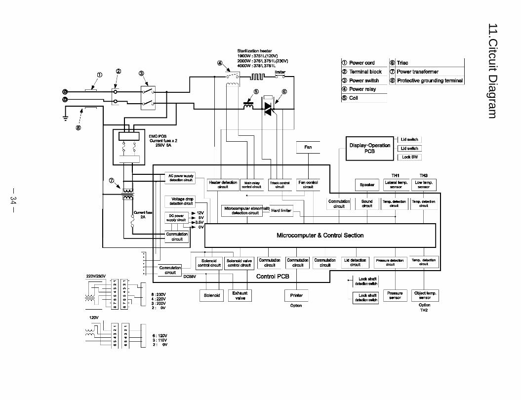
11.Citcuit D
iagram
CD I ~ :1
= ~ t~
® I
I
0)"
22OV123OV
· " " • · -- · ,
®
--I -
I
I EMCPCB Current fuaa x 2
'5OV SA
I
I AC power IlUpply ~ datecIIon circuit
;M '!'i' Voltage drop
detection cirtlUit
Sterilization heater 1900W : 3751 L(12OV) 2000W : 3751,3751 L(230V)
"~ 400OW:3781,3781L
nnnn limiter _ uuuu ~o--
= @ ®
-*-iY -
-
Heater detection Main relay ITriKk~""'" I circuit control circuit circuli
MlcrocompulBr abno
CD Power cord @Triac
® Tanninal block 0) Power transfonner
® Power switch ® Protective grounding
® Power relay
@Coil
----j Ud switch
Fan I
Display·Operation --1 Ud_h I ,- PCB '-""<ow
TH1 TH3
Fan control I circuit I 5 kef' I I Lateral temp. I I Low temp. pea sensor sensor
IComm~onll Sound II T __ II To~"""~ Circuit circuit d'cult circuit
"'''''' ... 12V DCpower E'! 5V
detection circuit all Hard limiter h
I I I
7
· " " • · · ,
>A IlUpply circuli -'!.5V
I L~ OV
CommutaUon circuit
.-- ~ I, S<>Ieoo;d III Sol~'" wlw .-
.- =1 Co~=on control circuit control circuit -
DC88V 1
8:23OV 4 :22OV 3 :200V 2: OV
6: 120V 3: 110V 2: OV
I I
I SolenoKj I I ~:st I
I
Microcomputer & Control Section
I I I
1 Commutation circuit
1 ComrTMJtation circuit
Commutation 1 circuit
Lid detection I I PrMeure dIlecIion 11 Tamp. dllectlon circuit circuit circuit
Control PCB l '-""< "'all, I delecllon SY!Ich
I ~ '-""< "all, I I P .... ,.. I I Objed tomp_ Printer del8clion swim sensor sensor
0 n Option ptio
TH'
tenninal

12.Troubleshooting
is not when the is turned ON.
Checking point by
tea .. ,
Check the conductivity
F ....
• od<el of
housing set
(1) main power billa •. If the breaker Is OFF, tum nON.
(2) Check the power cord for any breakage. If broken, replace the power cord.
(1) i the P0'NW5Upply. Tum OFF the main power supply and turn ON the power switch of the unit, and check the conductivity. If not conductive, replace tha power switch.
(2) Check the lead wire for removal or looseness.
ENTERA (or CE).
; Check tha lead wire for breakaga .
- 35-

(2) iIIILid" appears on the dsplay and procesl doe. not start. 1) Check the 2 shafts mounted to the nd. Push the shafts to make sure that they slide In and out
smoothly. Shafts If the shafts do not slide smoothly,
2) Check the position of the both lock shah.
Lock shafts
(1) Check the springs lItted to the shalls. (2) Apply grease to the shaft sliding perl
When the cover is opened, (1) Check if the shalls are in due position
On just about vertical position). (2) Check if the lock shafts open when pushlld outward and
they retum to the original position by spring force when relaased.
If they can not move normally, (1) Remove any foreign matter which is pinched and jams the
.hall (2) Replace the spring, etc. If In trouble. (3) Apply grease to the shaft sliding perl
- 36-

Between Black 1 and 2
Between Black 3 and White 1
Detection switch
Socket of the
housing H1:
Conductivity checking
positions • Detection switch 1
Between Black 1 and
2
• Detection switch 2 Between While 1 and
Black 3 • Wire Nos. are
Indicated on the
connectors.
i.,.,,;~ awIlch Is not conductive housing set M.
; lead wire for breakage.
housing set OS.
- 37-
ON, replace the
replace the

Check. the
connection.
Check that the housings in the same color are connected.
(3) "___ ..,.,..,.. on the _ even when the cover Is closed. 1) Check the Items 2) and 3) of "L.Jd" appears on the display Correct Kif In trouble.
and does not start 2) Check. the conductivity the switch when the both lock shafts Since the switch is turned OFF when the lock shafts open, the
switch Is not conductive. If the switch is conductive, rwplace the housing set M.
(5) _ is not .. "".... to tho twater. 1) Check the exhaust hose. Check. if the hose is bent or clogged in the product when
exhaust 'lank Is Installed. Correct Kif bent or clogged. 2) Check the hose in the exhaust tank. Check if the hose is bent or clogged.
Correct Kif bent or clogged. 3) Check if the exhaust hole i, blocked with any sterilization Remove it if the exhaust hole is blocked.
otfect or sterilization bag.
- 38-

Check the resistance
value bet¥Men the
terminal block 1 and
relay- 6.
1 and D.
,,-f- Press hera.
(8) ''!me" "-""" on tho _.
(1) Since does not operate in spite that the voltage is applied, replace the exhaust valve.
If the voltage is OV, (1) Check the connection of the housing set W or V. (2) Replace the "PCB set, controlTH set".
7.6Qfor 3751 L (12OV), 13.2Qfor 3781L 26.5Qfor 3751L (230V) and 3751. If not, replace the heeler.
(1) C;;eck.1~' ~)",;"g"' .. "'b'y I 3781 CE for connection and breakage.
(2) Replace the relay.
'''''''' OV. (1) Check the housing assemblyB120 3751 or 8220 3781 or
8230 3781 for conneclion or breakage. (2) Replace the Triac. (3) Replace the "PCB set, controlTH set".
chamber. It can be restored If a "Click" sound Is heard.
Check the Item. 1) - "') of ·Power is not not .upplied to the If any trouble, correct it heeler."
- 39-

(7) Steam leaks from the periphery of the chal'l"tter. 1) Check the chamber lid packing and the chamber hard top (1) Clean the contact pari of the packing and chambertop.
(8) Steam leaks from pipe and joint.
(2) Clean the contact pari of the packing and chamber lid. (3) If the chamber lid packing Is deter1orated, replace It.
1) Check the heater mounting pari (lower side of the chamber) If nuts are Iooeened, retighten them. for steam leakage.
Checking positions
2) Check the pipe connection (1) If the connection Is loosened, retighten It. 2 If the hose band is loosened, lace it.
(St) Open error (E1) occ .... , at the lateral thermistor (TH1). Abnonnal tern erature rise of the lateral thermistor E3 occurs.
1) Check the connector connection (1) Check if the socket is inserted completely. 2 Check the lead wire for brea 8.
2) Check the resistance value of the lateral thermistor (THl) Remove the connectors from the "PCB _, control
Checking points
bvtester
completion" and check the resistanoe value beiw8en the terminals of connector side. Resistance range (90 - Ilot):About SO.O-41.60)
3 Trouble with the "PCB set, conIroI TH set. Re lace the "PCB aet, control TH set".
(10) Abnormal t. .ratur. of the ob".ct t.m .rat ..... s.nsor (TH2) (E4.occurs.) 1) Check the resistance value If the object temperature sensor Remove the connectors from the "PCB set, control
Checking points
bv .....
2 Trouble with the "PCB set control TH set"
completion" and check the resistance value between the terminals of connector side. Resistance range (90 - Ilot):About SO.O -41.60)
Re ace the "PCB control TH set".
- 40-
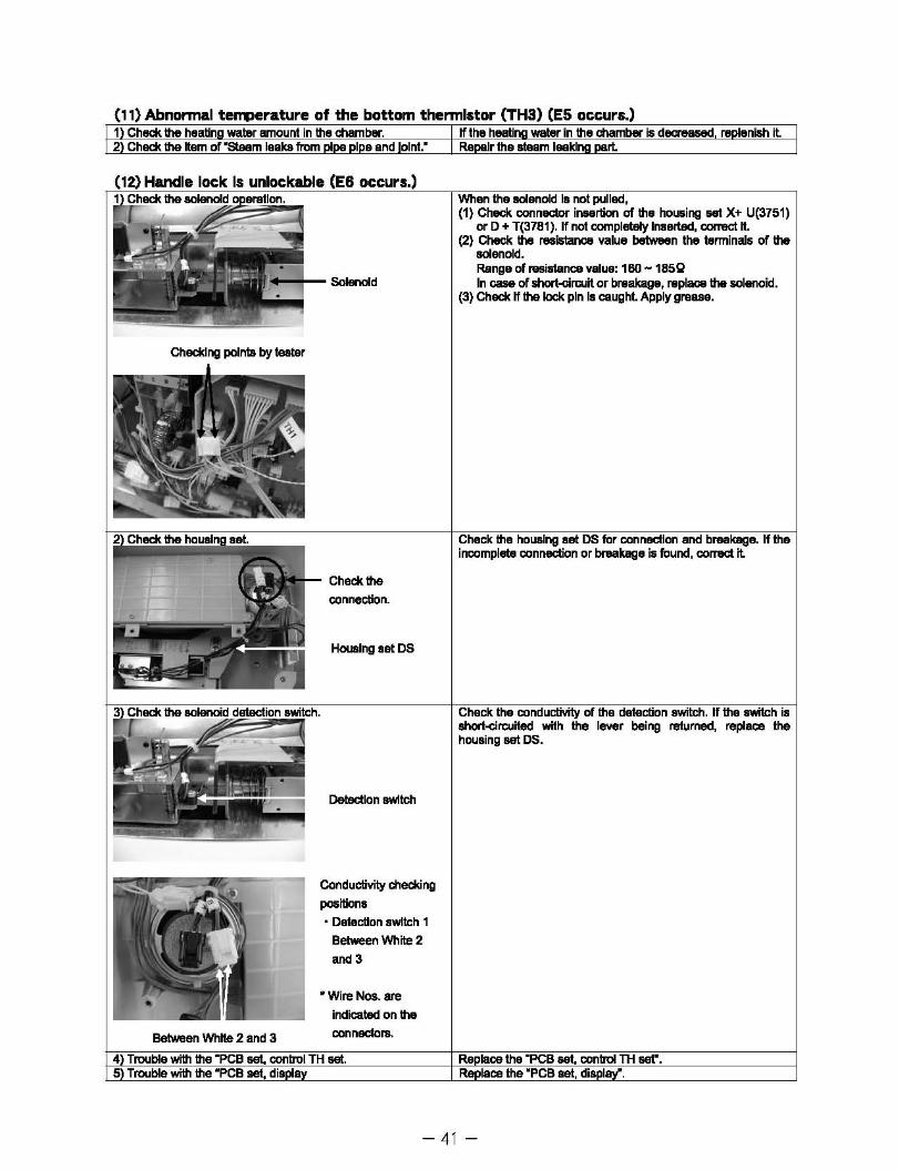
(11) Abnonnal teQJerature of the bottom thennlstor (TH3) (E5 occurs.) 1 Check the heBlin water amount in the chamb... If the heati water In the chamber is d .... Bled, re enish it 2 Check. the nem of "steam leaks from I e and oint." Re Ir the steam leakl rl
., .... +- SolenoId
Between White 2 and 3
connection.
Housing set DS
Detection switch
Conductivity checking
posilions
• DetecUon switch 1
Between White 2
.oo 3
* Wire Nos. are
indicated on the
connectors.
I (1) Check connector insertion of the housing set X+ U(3751)
or D + T(3781). If not completely Inserted, correct n. (2) Check the resistance value between the terminals of the
solenoid. Range of resistance value: 160 - 1852 In cue of short-an::uit or breakage, replace the solenoid.
(3) Check. If the lock pin Is caught. Apply grease.
incomplete
short-circuited with housing set DS.
lever being retumed, replace the
- 41 -

Movable handle and lid lock is not
BeIw'I!Ien White 1 and Black 3
r
Checking position
Detecllon switch
Conductivity checking
poanlons
• Detection switch 1 Between Black 1 and 2
• Detection switch 2
Between WhKe 1 and Black 3
• Wire Nos. are
Indicated on the
connect0r5
; for engagement of the lid. If not caught, (1) Remove any foreign matter, which maybe sticking. (2) If the lock shall retum spring is weakened, replace it (3) If the lock shaft does not move smoothly, apply grease.
Check the condudivity of the switch when is closed. If no conductivity, (1) Adjust the switch mounting poaition. (2) If no conductivity is found ever when the lever is pushed,
replace the housing set M.
If no conductivity, (1) Adjust the switch mounting position. (2) If no conductivity Is found ever when the lever Is pushed,
replace the housing set OS.
- 42-
4) Check the housing aet.
5 Trouble with the "PCB set, conlrOl TH ser e Trouble with the "PCB s dis la
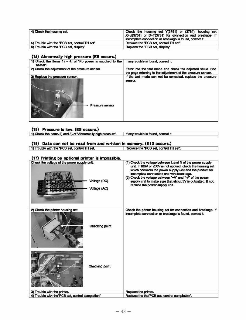
'--+- Pressure sensor
(15) Pressure is low. (E9 occurs.)
Check the housing set Y(3751) or (3781), housing set X+U(3751) or D+T(3781) fo~ connection and breakage. If Incomplete connecUon or breaKaae Is found, correct n. Re ace the "PCB set, control TH set". Re lace the "PCB set, dis I
.. nSOl'".
I 1) Check the Items 2) and 3) of "Abnormally high pressure". I If any trouble Is found, correct It.
(18) Data can not be read from and written in memory. (E10 occurs.) I 1) Trouble with the "PCB set, conlrOl TH set. I Replaoethe "PCB set, control TH set".
,l,.....,.- Voltage (DC)
p,...+- Voltage (Ae)
Checking point
Checking point
which connects incompl&la
(2) Check the voltage between "+V" and of the power supply unit to make sure that about W is outputted. If not, raplace the po'W'8I" supply unn.
,correct it.
- 43-
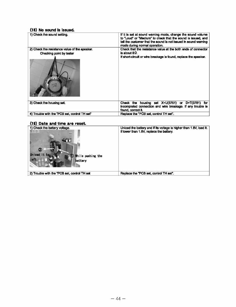
(18) No sound Is Issued. 1) Check the lKlund setting.
2) Check the resistance value of the speaker. Checking point by tester
3) Check the housing set.
4) Trouble with the "PCB set, control TH set"
If it is set at sound waming mode, change the lKlund volume to ~Loud" or "Medium" to check that the sound is issued, and tell the customer that the sound Is not luued In sound warning mode duri normal 0 eration. Check that the resislance value at the both ends of connector isabout8Q. If short-circuit or wire breakage Is found, replace the speaker.
Check the housing set X+U(3751) or D+T(3781) for incompleted connection and wire breakage. If any trouble is found, correct it. Replace the ~PCB set, control TH set".
Date and time~a~re~re~.~e~t~.------I~Oal~~~r"~"'!"'!'"!'''h\li'"'iiiOiiTW.Tci8diLl If lowar than
Ie pushi ng the
- 44-

13. Disassembling Procedure
.. ThIo p/'IcIII)t 1n .... 1Igurw ..... ,iPIIf) .... MocIaI MLS-37B1L which may dif'fwtcrn .... Model MLS-3751Llnh m.mber~Ia'IMS.
&'CAUTION &'CAUTlON WIwI , 1M.... . .... &
_ •. . ............... ~ lie produr:t, ~ .I s OA. ncJt lie PIOM:t. De ..-e w unpkig the
""-"",,,,,.L GOld hili .. will kl9111 ~ by ftrp ...... edgiI. w.r
(1) ~ tM pacldnl; fIf the churDer
CD IJiarnaurf: the paddng of .... chember. (~.-1 )
&. CAUTION CheQ the coating of adhMiYe before .. mounting •• pply adhutve (KE-44T) If ""'0'«1. Apply the adh .. ~ to all over the edge gf'OCMt. (See FiII.-2) (Drying time: 12 hou ... l
(J) DlIftIOIIItInc the PC-bovd uaentiy 101' control (Flg.-8)
CD DIk:onnec:t .... connectors connedecllo l'Ie PC-boiIrd auembly for amtrd.
I%l Dismount the board from the boerd mounting lpaoerl.
Packi"g of ... -
(4) DI~tlna the PCB aneriJly for EYC (FiII.-6)
CD DiK:onnect the connectonJ connllded to l'Ie PCB
.... mbly for EMC. [~~5' I%l DisIllOUli the board frtliTl the boerd mounting SpllCeri.
- 45 -

(I) Dlsmol6ltln. the ct-ah valve auentlly (Flg •. -7 end-8)
(]) Disconnect the connectors connected to the drain valve aaembly.
® I...oOIIIIn the hose band end disconnect it.
<3l Remove the orifice 1.8 joint.
® Dismount the solenoid vai'M set together with the T chamber joinL
(I) Dlsmol6ltlnc the .. athad hntar
<D Tum the tube counl8rclockMae to move it.
® Remove the ~r winsa, loosen the mounting nutl end dismount the healer from the chember. (See Flgs.-9 and -10.)
(7) Dlsmol6ltln. the lateral thennlrior (TH1)(Fig.-11)
<D L.ooNn the thermistor mounting BCI'8WI and dismount the thermistor end rubber ring.
(I) Dlsmol6ltln. the bottom thannlrior (THS)(Fig.-12)
<D I...oOIIIIn the thermistor mounting nuls and di.mount the thermistor end rubber ring.
(I) Dlsmol6ltlnc the SV camp. valve ... .,-DIy (FIg.-13) ~~§:
<D Loosen the mounting nut to dismount the SV compo valva assembly.
- 46-
; I

(10) Dismounting the pressure sensor (Fig-14)
CD Cut off the binding band and dismount the connectors from the board.
® Loosen the mounting nut and dismount the pressure sensor.
(11) Dlsmountln. the front panel (Fig.-15)
CD Make sure that the chamber is not filled with water.
(%l Tum the lever of the water drain to ·Open-.
@ Remove the 8 front panel mounting screws.
® Dismount the front panel, paying attention to the switch cover.
(12) Dlsmountln. the lock shaft switch (M Housing assembly) (Figs.-16 and -17)
CD Disconnect the connectors connected to the switch.
(%) Remove each 1 saew which ftxes the switch.
;«CWhen dismounting the switch, pay attention
not to allow a tool or finger(s) to hit the ectuator of the micro-switch. Otherwise, the
(13) Dismounting the pressure gauge (Figs.-18 and -19)
CD Remove the cap nut for piping of the pressure gauge.
(%) Remove the saews (3 pes.) which fIX the pressure gauge. Cap nut
* Pay attention not to lose the O-ring (P5) which is
inserted between the pressure gauge and the pipe. Also, do not tighten the cap nut too much
(14) Dismountin. the breaker (Fig.-20)
CD Remove the 4 wires.
(%) Remove the 2 breaker mounting screws.
- 47-
*·0· shows the saew position.
s .......
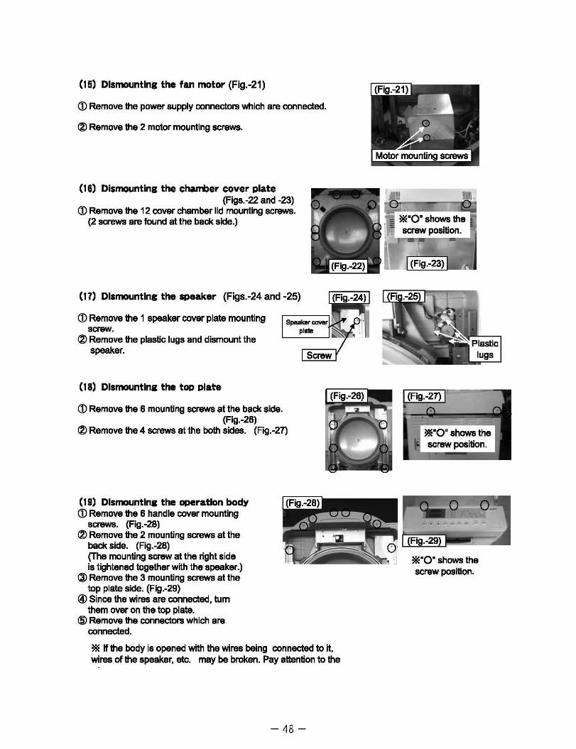
(15) Dismounting the fan motor (Fig.-21)
CD Remove the power supply connectors which are connected.
(2) Remove the 2 motor mounting screws.
(16) Dismounting the chllJTi)er cover plate (Figs.-22 and -23)
CD Remove the 12 cover chamber lid mounting screws. (2 screws are found at the back side.)
(17) Dismounting the ..,e.ke. (Figs.-24 and -25)
<D Remove the 1 speaker cover plate mounting screw.
(%) Remove the plastic lugs and dismount the speaker.
(18) Dlsmountlna: the top plate
CD Remove the 6 mounting screws at the back side. (Fig.-26)
(%) Remove the 4 screws at the both sides. (Fig.-27)
(19) Dlsmountlna: the operation body CD Remove the 6 handle cover mounting
screws. (Fig.-28) (%) Remove the 2 mounting screws at the
back side. (Fig.-28) (The mounting screw at the right side is tightened together with the speaker.)
@ Remove the 3 mounting screws at the top plate side. (Fig.-29)
@ Since the wires are connected, tum them over on the top plate.
@ Remove the connectors which are connected.
Screw
* If the body is opened with the wires being connected to it. wires of the speaker. etc. may be broken. Pay attention to the
- 48-
screw position.

..... iIt) CD FWnove the 5 board coni. cover_
mounting sa'eWII. (FIg.-30)
CZl RemCMil the 5 display P~aard • ...."bly mounting 8CI8W1I. (Fill.-31)
(J) Remove the plastic lup. (FIII.-31)
(21) R •• 1CMnc the braD ~
(J) RfImcwe the 2 tnb Igt*"*'ll- .-III cIiImounl the bi'ab upper I'iand bIwJtat.
(Flg . ..32) !%l L.Doaen and nirT10Ye the 2 brake mounting
Icrewt;. (Flg . ..33)
(n) Rernr:mn. the rW1t and left t'*w;. IDf"Inp
(J) RMIoYe the heIoagoIlIIlCI'WIIlI'I'IictI lad: Ow spdngL (See Aga.-34 .-III 35.)
I%l RernCMiI!tIe" hind bracIwt iIPI1nII mounIIng right and IIrft ~.
(J) Remove the I'eanhaft look ring.
!&) Fully open IhIlkllUid pullout th ..... 1' ltuttt.
(J) Remove !tie " top .. 1tIng .,.... mcu'ltftg ~ (F1g.-38)
(2) PuI 0I.t the bush tom the ....... oedor. (Fig.-38)
(Jl RfIrnoye the 2 look st.lllCllYale pl. mounting 8CI8WS. (FIII.-37)
® Mlllumly unlock the lock shaft and dismount theloc:k sl'lRl't actlYa pi... (FIQ.-37)
($) FWnove the " KI'8WS at the batI 8idee d !hi hIncII support plele ...mbt;. (Ag.-3B)
- 49-

~ Ranowt the 04 .... Ibid Ib1I pate mounting....-. (Rg.-38)
C%l RarrIclw.IM 2 solenoid mounIng a.cr-.. (Flg . ...tO)
!II CUt 011' the binding bene!. (Flg.CO)
!II: When dismounting the eoIenoid menuelly, p.y .tt.nUon not to allow tool and ftngar(l) Ie hit tha aoillnoid switch actuator. Otherwillll, tIMI ec:tJator may be 1WFTIOWd.
(M) DbmcurtInI the .... Md twttch and lei twitch (Ie '-II,.. ..... 1') (Flg. .... 1)
cr> Ranowt the 1 .... 00 IWIt!;h mounting 1ICI8W.
(%l RemOlll'e the 2 aaews of each of the IWItch ftttIng plate.
C!l Ramova aad11 lid switch mounting Icr.w.
tal Cut orr 1M binding band.
!II: 'It'hen diImounting the .... 00 awik::l'l a'ld lid bOik:h. ~ ata.ntIon not to allow \001 and tngar(1) to ~ the aoIenoid B'IIII'i1UI Jduator. othIII .... , the actuar may IM_nowel
- 50-