I E copvl i fO. 1 - NASA · yawing moments are ... PARTICULAR CEARACTERISTICS OF AERODYNAMIC FORCES...
11
. l i . 1 I r I E copvl fO. "1 o HATIOHAL ADVISOHY COt. naT TEE FOR as No. 772 THE DENIS-GRUSON SIX-COMPONENT WIND-TUNNEL BALANCE THIS ON LOAN FROM THE FILES OF NATlOHAl ADVISORY COMMlffiE FOR WGI.£Y A[RONAIJTI(',AL LABOf<ATORY LANGLEY fIELD. VIR61NIA RfTURN TO i REQlJESTS PUB' ICAT ONS SHOULD BE ADDRESSED NATIONAL lOVISORY COMMmEE FOR 112-1 STRtEl. N.W YtA<:H NC''"OIi' I) C. Washington July 1935 https://ntrs.nasa.gov/search.jsp?R=19930094645 2018-07-16T19:04:58+00:00Z
-
Upload
truongkhanh -
Category
Documents
-
view
217 -
download
0
Transcript of I E copvl i fO. 1 - NASA · yawing moments are ... PARTICULAR CEARACTERISTICS OF AERODYNAMIC FORCES...

. l i .
1
I
r I E copvl fO. "1
o
HATIOHAL ADVISOHY COt.naTTEE FOR AER01~AUTI as
No. 772
THE DENIS-GRUSON SIX-COMPONENT WIND-TUNNEL BALANCE
THIS DOCUM~T ON LOAN FROM THE FILES OF
NATlOHAl ADVISORY COMMlffiE FOR ~ERONAIJTICS
WGI.£Y MEf'ORI~l A[RONAIJTI(',AL LABOf<ATORY
LANGLEY fIELD. HA~PTON. VIR61NIA
RfTURN TO T~t A~O i &D~RESS.
REQlJESTS ~Ok PUB' ICAT ONS SHOULD BE ADDRESSED
~ ~OLWWS
NATIONAL lOVISORY COMMmEE FOR ~ERONAUTICS
112-1 STRtEl. N.W YtA<:H NC''"OIi' I) C. Washington
July 1935
https://ntrs.nasa.gov/search.jsp?R=19930094645 2018-07-16T19:04:58+00:00Z

NATIONAL ADVISORY COMMITTEE FOR AERONAUTICS
TECHNICAL MEMORANDUM NO . 772
THE DE1US-GRUSOllT SIX.,.COliiPOi:n.nrT WIND-TmrNEL BAL.A..LITCE*
INTRODUCTIO~T
The aerodynamic study of a model in t he wind tunnel necessitates, as a rule, the measurement of six components: the three components of the general resultant and the three co mponents of the resultant moment.
These six components, measured with respect to a sys~ ter.l of wind (or tunnel) axes, are as follows: lift, drag , sideslip, pitching moment, rolling moment. and yawing moment. (For reasons of clarity the pitching , rolling, a nd yawin g moments are referred to a system of wind axes and no t t o a s y stem fixe d in the model.)
r:i:hus, to be suitable for all exp erimental cases, a wind-tunnel balance must be a b le to measure these six compO i.len t s.
PARTICULAR CEARACTERISTICS OF AERODYNAMIC FORCES
Quite oft e n t h e wind-tunnel measurements are beset wit h g reat d i f ficulties because of the very peculiar characteris t ics of the phenomena in play . Briefly, these ch aracteristics are:
a) The existence of unstable or transient phenomena with rapid changes (in3tability of certain airfoils at zero lift, multiple and transient re~ gimes (velocities) at high angles, appearance of moments of instability at high angles, alternating turbulent flow, etc.);
b) Variations in the nature of the phenomena, part~cularly in t he case of successive experiments (changes in air-stream turbulence, response to unstable phenomena at high angles);
*"Balance dynamome trique a six composa:ltes SystEna6 G.I!

2 li,A.C.A. Technical Memorandum No. 772
.c) Direct relationship between the forces and the quite often not very stable speed of the air stream;
d) Human element.
These factors preclude the idea of using a balance employing weights or sliding wei6hts or any other balance of similar characteristics, but favor the use of recording devices with r~latively small natural period and concurrent and continuous recording of the loads, angle of nttack. and the air speed.
WIND-TUNNEL BALANCES
The most elementary kind of such a balance consists in the juxtaposition of the following six balances:
Two balances for the front lift
One balance for tho rear lift
Two balances for the drag
One balance for the sideslip
Hereby the lift and the total drag are obtained by adding the readings from the corresponding balances; the rolling Lloment is obtained by deducting the readings from the front lift ~al~nces. etc.
Unfortunately, the practical disadvantages of such a balance tend to its rejection. For example, the loads in rolling are in the majority of cases small as compared to the forces of the front lift; nevertheless, they arB measured with the same front lift balances. The relative instrumental accuracy is thus much lower in rolling than in lift. and certain changes in rolling mQment may even pass unnoticed in certain cases.
These facts have led to the attempt of measuring the rolling and yawing moments with balances operating differenti a lly on the front lift wires and the drag wires, these balances being supported by the front lift and the drag balance.

£;' •. P... C .A. Technical Memorandum Ho. 772
PRINCIPLE OF EALANCES USED
The balances employed (Gruson balance) are of two types: the simple and the parallelogram.
3
Both types are b~sed on the principle of flat . springs with low rate of deflectioll (0.4 to 0.01 mm).
The simple balance (fig. 1) consists of a spring R clamped at one end and actuated at the other by the force to be measured ~ This spring has an extension, a rigid piece p, which forms the amplifying lever. The end of this piece actuates the thin spring r (in form of an arch) whic~ carries the concave mirror M. The different parts are linked by clamps; thus the whole can be shifted wit~out friction .
An oil dashpot with adjustable port is fitted between the a mplifying lever and the base. The plunger of this dashpot, clamped. in the lever, moves in tho cylinder withou t friction; sufficient clearance is provided between the plunger and the cylinder.
The light beam from a lamp with straight filament is thrown on the concave mirror , and its reflection is pho t ogr~phed on the recording cylinder (fig. 1).
For the purposes of measuring a force in a certain direction, or even to superpose two balances (parallel displacement of the balance carried by the other), the dia g ram of the elasti c balance has been modified to give the balance with elastic parallelogram (fig. 2).
This balance consists of two flexible plates Rand R' clamped. at their two ends in such a manner as to (orn a parallelo g ram with clamping pieces . One of these clamping pieces is integ ral TIith the base; the force to be measured is applied at the other.
Under the action of the force the plates are elastically disp laced in the form of an S, an inflection point at mid-l ength.
Rand. R' presenting
The stiff piece P forming the a:nplifying lever effects the tang ent o f the inflection to one of the plates; as in the Si li:p le bal ance, t his piece actuates a secondary spring carrying the concave mirror M. A dashpot is fitted between piece F and the base.
4 B.A.C.A. Technical Memorandum No. 772
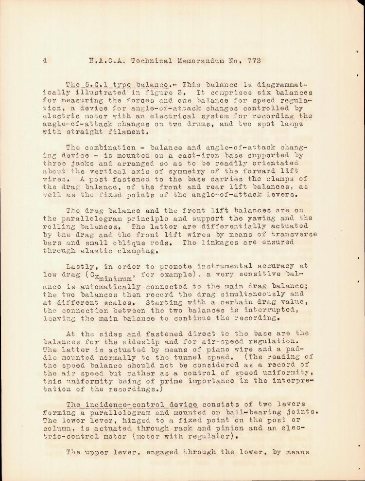
~~t~._£.d2.!1._ tn)~_-t?~;I,.fL"~C"~. - T:li s balan ce is diagramma tically illustrated i~ fiGure 3. I t co lpr ises six balances for measuring the forces and one balance for sp eed regulation, a device for aagl e-0f-atta~k changes controlled by electric motor ~ ith an electrical system fbI' recording the angle-of-attack change s O!'l t'i70 dru!!ls, and tYro Sl)ot lal!lps with straiBht filament.
The combina t ion - balance a~d a n g le-ai-attack c~anglng dovice - is mounted on a cast-iron base supporte d by three jac-:s and arrangecl so as to be readil;yr orientated about th e vertica l axis of symmetry of the forward lift wiren . A post fastened to the base carries the clamps of the dra~ balance , of the front and rear 11ft balances. as ~ e l l as the fixed points of the angle-of - attack levers.
Th e drag balance and the front lift balances are on the parallelogram principle and support the yawing and the rolling balances . The latter arB differentially actuated by tho dra~ and the front lift wires by means of transversa bars and small oblique rods. Tho linkages are ensure d throug h elastic clamping.
Lastly, in order to promote instr~mental accuracy at low drag (C., .. • for example), a 'Tery sensitive bal-
'-"m lon J. l1r~m ance is aU"Gomatically connected to t:'le main drag balance; the t\70 balances th en record the drag simultaneous ly and at different scales . St ar ting with a certain drag value, the CO~1ne ct ion between the two balance s 1. s in t errup ted, lcavi~s the main balance to continue tho recording .
At the sides and fastened direct to tho base are the balances for the sideslip and for air- spe~d regulation. ~he latter is actuated by ~eans of piano wire and a paddle jrlounted normally to the tunnel -;'peed . (The reading of t h e speed balance should not be considered as a record of tho air speed but rather as a control of speed uniformity, this u niformity being of prime importance in the interp retation of the recordings.~
The incidence-control dovico consists of two levers f 0 rmi~g" -~-:p~r~lleio-g";,:;~-;n-d-~~;;~nt-ad on ba 11- bear ing j a in t s. The lower lever, hinged to a fixed point on the post or column, is actuated thrOUGh rack and pini on and an electric-control motor (motor with re gu lator).
Tlle upper lever, engagecl through the lower I by means

lLA.C • .A. Technical Memorandum No. 772 5
of small vertical rods, is linked at t he front to the rear lift balance; at the other end i t is actuated by the rear lift wire connected to the ~odel. A convenient device actuating the angle-of-attack mirror is fastened at the hinge of the lower lever.
The recording drums and the spot lamps are mounted on a small pedestal attached by means of a steel tube of large diameter. One drum records the drag with normal sensitivity, the drag with great sensitivity, the front lift, the rear lift, the speed, t he setti~g of the model; while the other drum registers the y awing moment, the l' 0 11 in g mo men t, t 11. e sid e s 1 i p, and. the set tin g 0 l' the I.10 del.
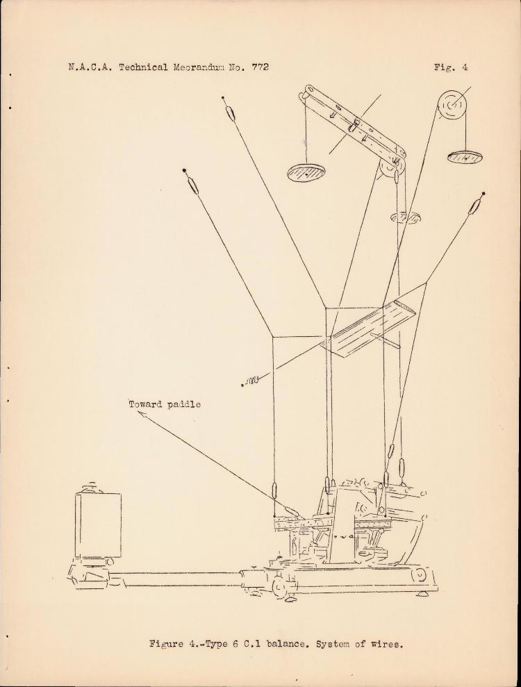
The drums are simultaneously controlled by the electric motor; the recordings are conjugated either through the ang le-o f -at tack recording curves o r through st op ma rks mao.e by the operator during recording '.1ith a special l amp. Such a balance may , obviously , be link e d to the model throu~h any system of wires. In the drawing (fig. 4) we show an especially simp le ar rangement wh ich has proved v e ry satisfact or y .
The 6 .C.l b a lance lends itself, moreover, to arrangemen ts which may be valuable. In particular, its angle-ofattack chang ing me chanism permits of ready linkage of the weighed mod el to a secondary model. Th e latter, fastened to a separate support (specia l set of wir es), may i n fact be actuated by the lower angle-of-attack lever. ('1.1h1s lever d oes n ot enter in the weighing .) Then t he angle-of- attack changing mechanism controls concurrently the setting of th e weighed model (upper l ever ) and the secondary model (lower lever). This arrangement is app licable in the very interesting case of tests in plane flow between panels f or the control of guard tips, in bip lane tes ts, in tests o n wings with fuuela g e, e tc.
The polars may als o be established with this balance by simply rotating the ba l ance and the upper attachment points about the vertical axis situated in the plane of the front lift wires. This axis is, moreov e r, realized on the balance by a centering p iece fas tene d below the base.
All controls of the ba lance arB assured through five push buttons and a reversing switch located along with the con t rol lamps to the rear of the base . The operation of the balance f or one record is limited to starting the motors, lighting the l amp s, and reverse maneu vers when the

6 H.A.C.A. Technical Memorand"..1.m iJo . '772
limit of the angle of attack is r eacheu. a t i 0 11 t ak e s fro ill 3 tal 0 ~n i ~1U t e s. )
(Tll e who Ie op er-
This wholly automatic op erati on of the balance permi ts it to be mounte d in an airti~ht case and to be co ntrolled fro n the outside , ~~ich ronders it particularly suitable for high-speed or va riable-density wind tunnels (compressed or rarefied air).
CONCLUSION
The G.C.l ba lance (fig. 5) is the first fully autoJ1lr.1,tic 'balanc e assuring a c O'l tinu ou s and simultaneou13 rec oru of the aerodynarei e characteristics of a n a irfoil i n the ~i~d tunuel (fig. 6).
Tho necessity of nimu ltaneouD records is well understood by all who have searched to deter~ ine the unstable phenomena of aerodynami cs, such a s at h i gh ang l es of attack , for exanple.
The continuous recoru, only one parameter being variable (ang le of at tack , for instanc e), likewise p~csents an illclisiJut ablc advantage over the lIpoint by poin tll measur ements which, no matter be w closo tho experimental poin ts are, ffi1.S t be Graphically interpolated , whi c~ constitutes a source of error .
The C.C.I balance permits very quick wind- tu11i.1.el work uith lc s!".) personnel, which p ro por'tionally augmentB the efficiency of the laboratory.
Because of the rapidity of the measurements a co mplete p olar ( :::Jix co mp O :'le~ ts) requires on ly about three minu tes of wind , that is to say , of mo t ive p ower, which is of interest for uind tunnels with high efriciency fac tors and ,may le:J.d to the eCOllomical d,enign of l:J.rge-sizo wind 'G1.::.!me 1 s.
Da ta received f ro m ?a ris Office, N. A.C.A.
Translation by J . Vauier, Uattonal Advisory COl:'.mittee for Ae ronaut ics.

lIT .A. C.A. Technical !vIenoro,ndur:; lTo . 772
I I i
1 - -1-.----I --. __ I ~ -- -
I Recording /. -- -- - __ I drum I F -- -- --. -_ .. I --__ M
I 1- - .- --~ -- - - - - _. - - - - -' - - - -~ r
'------r---.--.l ;;:J ----SL
Figs. 1,2
I I --~.-
I -/;) R ~ , , / P __ . I / ~/)//.//-I
Figure 1.- SiTIple ba l anc e .
~~-- l- --I .- - M
Re=ing I ~ R - "- . -" - -'. -- - - - :.. :::~n r i ~~~ - -- .. -----B:::::.::::: .. ~.-_r-~. - .- - - -' r \ I /. -- - - --- -,,::,~,p ".W-I -;,t .- ---' --
L_-r-_l--.---- :~I
I ~ J I :~ R' I j--- -8--------~ .J
Figllre 2. - Para1l61 ogr ar:J ba lance.

o~ Speed
J'1gure 3.-6-compon8l1t balance, ° type .4..
A Roll1D& I
/ 1 "
End v/(?W
Jzf • .. • o • ~ • iii
of
! II::
I
t ~ • ..., ~
~ If 6J
N.A.C.A. Technical Meor andu':1 no . 772
\
"Towar d paddl e ~
1-_1 1- '--1(\
f 'L:~~\ -" -------------~ J---- ,\-------- - \
Figur e 4 .-Type 6 C.l bal anc e. Sy stem of wires .
Fig . 4
z:s

N.A. C.A. Technical Memorandum No. 772
Figure 5.- The 6.C.1. balance.
.Figure 6.Record of characteristics of airfol1s.