I c engine
42
I.C.Engine I.C.Engine Prepare by:- Shivkumar Panjabi 1 Prepare by:-Shivkumar Panjabi Prepare by:-Shivkumar Panjabi
-
Upload
shiv-panjabi -
Category
Education
-
view
1.359 -
download
1
Transcript of I c engine
I.C.Engine I.C.Engine
Prepare by:- Shivkumar Panjabi
1
Prepare by:-Shivkumar PanjabiPrepare by:-Shivkumar Panjabi

2
Introduction :=
• Heat engine : It can be defined as any engine that converts thermal energy to mechanical work output. Examples of heat engines include: steam engine, diesel engine, and gasoline (petrol) engine.
• On the basis of how thermal energy is being delivered to working fluid of the heat engine, heat engine can be classified as an internal combustion engine and external combustion engine.
2Prepare by:-Shivkumar Panjabi
• In an Internal combustion engine, combustion takes place within working fluid of the engine, thus fluid gets contaminated with combustion products.
– Petrol engine is an example of internal combustion engine, where the working fluid is a mixture of air and fuel .
• In an External combustion engine, working fluid gets energy using boilers by burning fossil fuels or any other fuel, thus the working fluid does not come in contact with combustion products.
– Steam engine is an example of external combustion engine, where the working fluid is steam. 3Prepare by:-Shivkumar Panjabi
Internal combustion engines may be classified as : – Spark Ignition engines.– Compression Ignition engines.
• Spark ignition engine (SI engine): An engine in which the combustion process in each cycle is started by use of an external spark.
• Compression ignition engine (CI engine): An engine in which the combustion process starts when the air-fuel mixture self ignites due to high temperature in the combustion chamber caused by high compression.
– Spark ignition and Compression Ignition engine operate on either a four stroke cycle or a two stroke cycle.
4Prepare by:-Shivkumar Panjabi

• Four stroke cycle : It has four piston strokes over two revolutions for each cycle.
• Two stroke cycle : It has two piston strokes over one revolution for each cycle.
• We will be dealing with Spark Ignition engine and Compression Ignition engine operating on a four stroke cycle.
5Prepare by:-Shivkumar Panjabi

6Prepare by:-Shivkumar Panjabi
Internal combustion Engine Components:I.C. Engine components shown in figure1 and figure2 are
defined as follows: • Block : Body of the engine containing cylinders, made of cast iron or
aluminium.
• Cylinder : The circular cylinders in the engine block in which the pistons reciprocate back and forth.
• Head : The piece which closes the end of the cylinders, usually containing part of the clearance volume of the combustion chamber.
• Combustion chamber:Combustion chamber: The end of the cylinder between the head and the piston face where combustion occurs.
– The size of combustion chamber continuously changes from minimum volume when the piston is at TDC to a maximum volume when the piston at BDC.
7Prepare by:-Shivkumar Panjabi
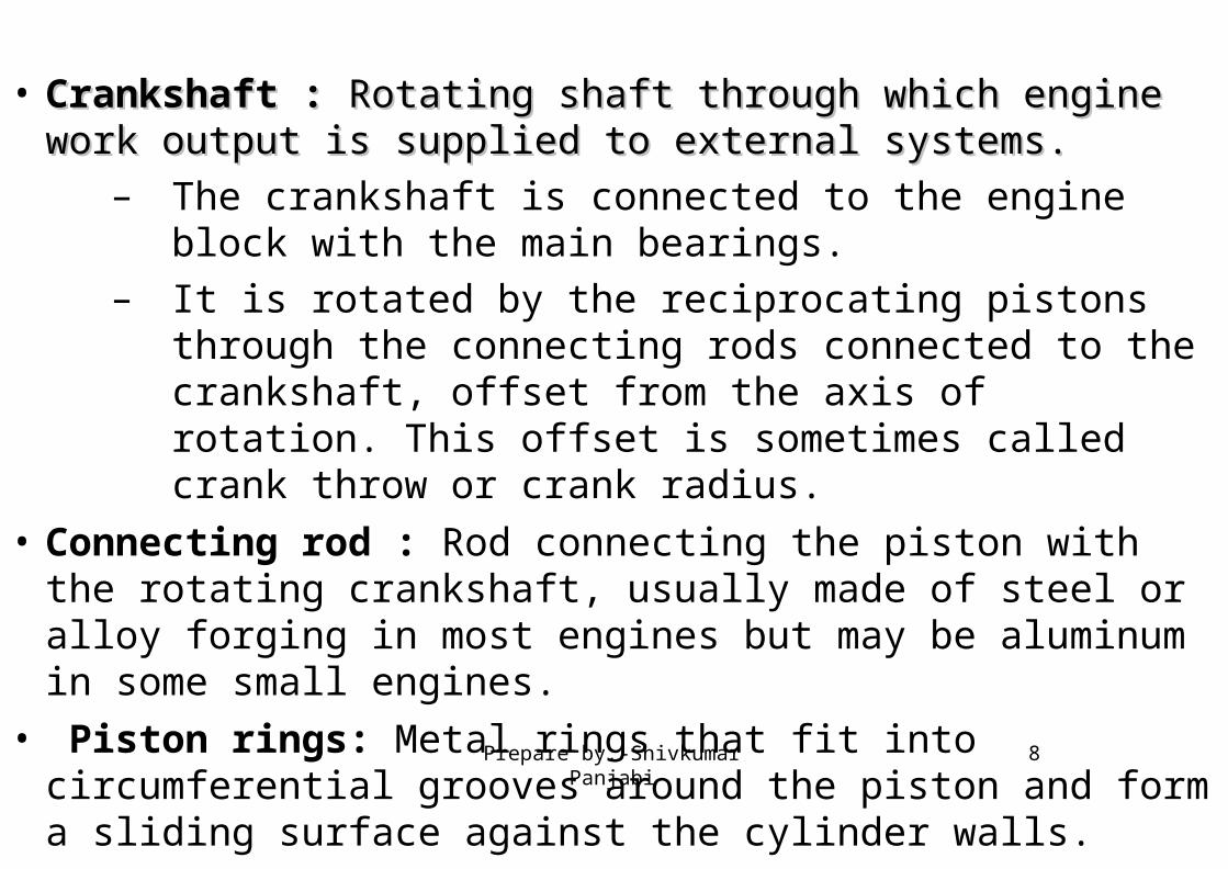
• Crankshaft :Crankshaft : Rotating shaft through which engine work output is Rotating shaft through which engine work output is supplied to external systems. supplied to external systems.
– The crankshaft is connected to the engine block with the main bearings.
– It is rotated by the reciprocating pistons through the connecting rods connected to the crankshaft, offset from the axis of rotation. This offset is sometimes called crank throw or crank radius.
• Connecting rod : Rod connecting the piston with the rotating crankshaft, usually made of steel or alloy forging in most engines but may be aluminum in some small engines.
• Piston rings: Metal rings that fit into circumferential grooves around the piston and form a sliding surface against the cylinder walls.
8Prepare by:-Shivkumar Panjabi
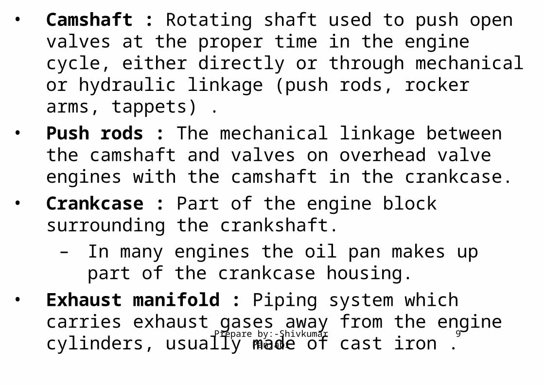
• Camshaft : Rotating shaft used to push open valves at the proper time in the engine cycle, either directly or through mechanical or hydraulic linkage (push rods, rocker arms, tappets) .
• Push rods : The mechanical linkage between the camshaft and valves on overhead valve engines with the camshaft in the crankcase.
• Crankcase : Part of the engine block surrounding the crankshaft.– In many engines the oil pan makes up part of the crankcase
housing.
• Exhaust manifold : Piping system which carries exhaust gases away from the engine cylinders, usually made of cast iron .
9Prepare by:-Shivkumar Panjabi
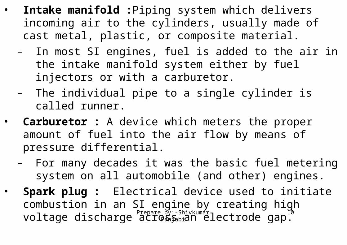
• Intake manifold :Piping system which delivers incoming air to the cylinders, usually made of cast metal, plastic, or composite material.
– In most SI engines, fuel is added to the air in the intake manifold system either by fuel injectors or with a carburetor.
– The individual pipe to a single cylinder is called runner.
• Carburetor : A device which meters the proper amount of fuel into the air flow by means of pressure differential.
– For many decades it was the basic fuel metering system on all automobile (and other) engines.
• Spark plug : Electrical device used to initiate combustion in an SI engine by creating high voltage discharge across an electrode gap.
10Prepare by:-Shivkumar Panjabi
• Exhaust System: Flow system for removing exhaust gases from the cylinders, treating them, and exhausting them to the surroundings.
– It consists of an exhaust manifold which carries the exhaust gases away from the engine, a thermal or catalytic converter to reduce emissions, a muffler to reduce engine noise, and a tailpipe to carry the exhaust gases away from the passenger compartment.
• Flywheel : Rotating mass with a large moment of inertia connected to the crank shaft of the engine.
– The purpose of the flywheel is to store energy and furnish large angular momentum that keeps the engine rotating between power strokes and smooths out engine operation.
I.C. Engine components apart from components shown in the figure:
11Prepare by:-Shivkumar Panjabi
• Fuel injector : A pressurized nozzle that sprays fuel into the incoming air (SI engines )or into the cylinder (CI engines).
• Fuel pump : Electrically or mechanically driven pump to supply fuel from the fuel tank (reservoir) to the engine.
• Starter : Several methods are used to s start IC engines. Most are started by use of an electric motor (starter) geared to the engine flywheel. Energy is supplied from an electric battery.
12Prepare by:-Shivkumar Panjabi
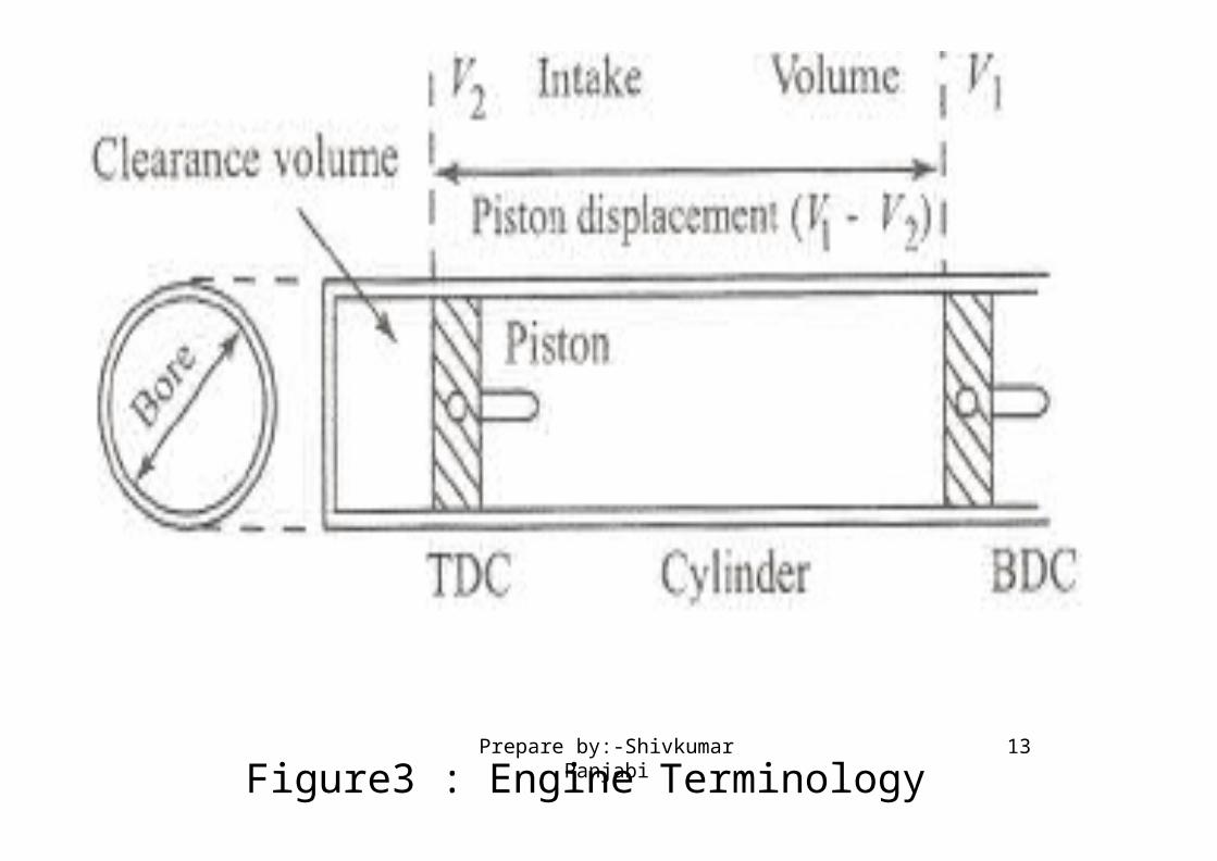
Figure3 : Engine Terminology13Prepare by:-Shivkumar Panjabi
Figure 3, shows the pressure volume diagram of ideal engine cycle along with engine terminology as follows:
• Top Dead Center (TDC): Position of the piston when it stops at the furthest point away from the crankshaft.
– Top because this position is at the top of the engines (not always), and dead because the piston stops as this point. Because in some engines TDC is not at the top of the
engines(e.g: horizontally opposed engines, radial engines,etc,.) Some sources call this position Head End Dead Center (HEDC).
– Some source call this point TOP Center (TC).– When the piston is at TDC, the volume in the cylinder is a
minimum called the clearance volume.
Engine Terminology :
14Prepare by:-Shivkumar Panjabi

• Bottom Dead Center (BDC): Position of the piston when it stops at the point closest to the crankshaft.
– Some sources call this Crank End Dead Center (CEDC) because it is not always at the bottom of the engine.Some source call this point Bottom Center (BC).
• Stroke : Distance traveled by the piston from one extreme position to the other : TDC to BDC or BDC to TDC.
• Bore :It is defined as cylinder diameter or piston face diameter; piston face diameter is same as cylinder diameter( minus small clearance).
• Swept volume/Displacement volume : Volume displaced by the piston as it travels through one stroke.
– Swept volume is defined as stroke times bore.
– Displacement can be given for one cylinder or entire engine (one cylinder times number of cylinders).
15Prepare by:-Shivkumar Panjabi

• Clearance volume : It is the minimum volume of the cylinder available for the charge (air or air fuel mixture) when the piston reaches at its outermost point (top dead center or outer dead center) during compression stroke of the cycle.
– Minimum volume of combustion chamber with piston at TDC.
• Compression ratio : The ratio of total volume to clearance volume of the cylinder is the compression ratio of the engine.
– Typically compression ratio for SI engines varies form 8 to 12 and for CI engines it varies from 12 to 24
16Prepare by:-Shivkumar Panjabi
SI Engine Ideal Otto Cycle
• We will be dealing with four stroke SI engine, the following figure shows the PV diagram of Ideal Otto cycle.
17Prepare by:-Shivkumar Panjabi

18Prepare by:-Shivkumar Panjabi

Figure4: Suction stroke19Prepare by:-Shivkumar Panjabi
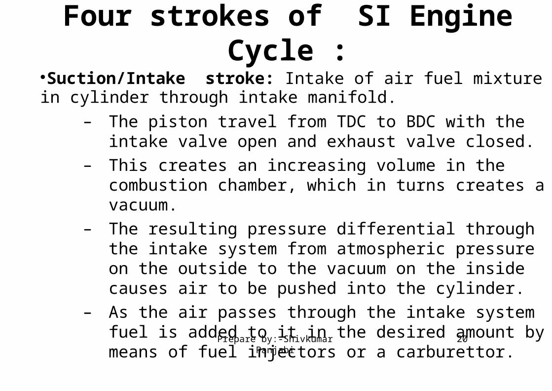
Suction/Intake stroke: Intake of air fuel mixture in cylinder through intake manifold.
– The piston travel from TDC to BDC with the intake valve open and exhaust valve closed.
– This creates an increasing volume in the combustion chamber, which in turns creates a vacuum.
– The resulting pressure differential through the intake system from atmospheric pressure on the outside to the vacuum on the inside causes air to be pushed into the cylinder.
– As the air passes through the intake system fuel is added to it in the desired amount by means of fuel injectors or a carburettor.
Four strokes of SI Engine Cycle :
20Prepare by:-Shivkumar Panjabi

Figure5: Compression Stroke21Prepare by:-Shivkumar Panjabi
• Compression stroke: When the piston reaches BDC, the intake valve closes and the piston travels back to TDC with all valves closed.
– This compresses air fuel mixture, raising both the pressure and temperature in the cylinder.
– Near the end of the compression stroke the spark plug is fired and the combustion is initiated.
22Prepare by:-Shivkumar Panjabi
• Combustion of the air-fuel mixture occurs in a very short but finite length of time with the piston near TDC (i.e., nearly constant volume combustion).
– It starts near the end of the compression stroke slightly before TDC and lasts into the power stroke slightly after TDC.
– Combustion changes the composition of the gas mixture to that of exhaust products and increases the temperature in the cylinder to a high value.
– This in turn increases the pressure in the cylinder to a high value.
23Prepare by:-Shivkumar Panjabi

Figure6: Combustion followed by Expansion stroke. 24Prepare by:-Shivkumar Panjabi
• Expansion stroke/Power stroke : With all valves closed the high pressure created by the combustion process pushes the piston away from the TDC.
– This is the stroke which produces work output of the engine cycle.
– As the piston travels from TDC to BDC, cylinder volume is increased, causing pressure and temperature to drop.
25Prepare by:-Shivkumar Panjabi
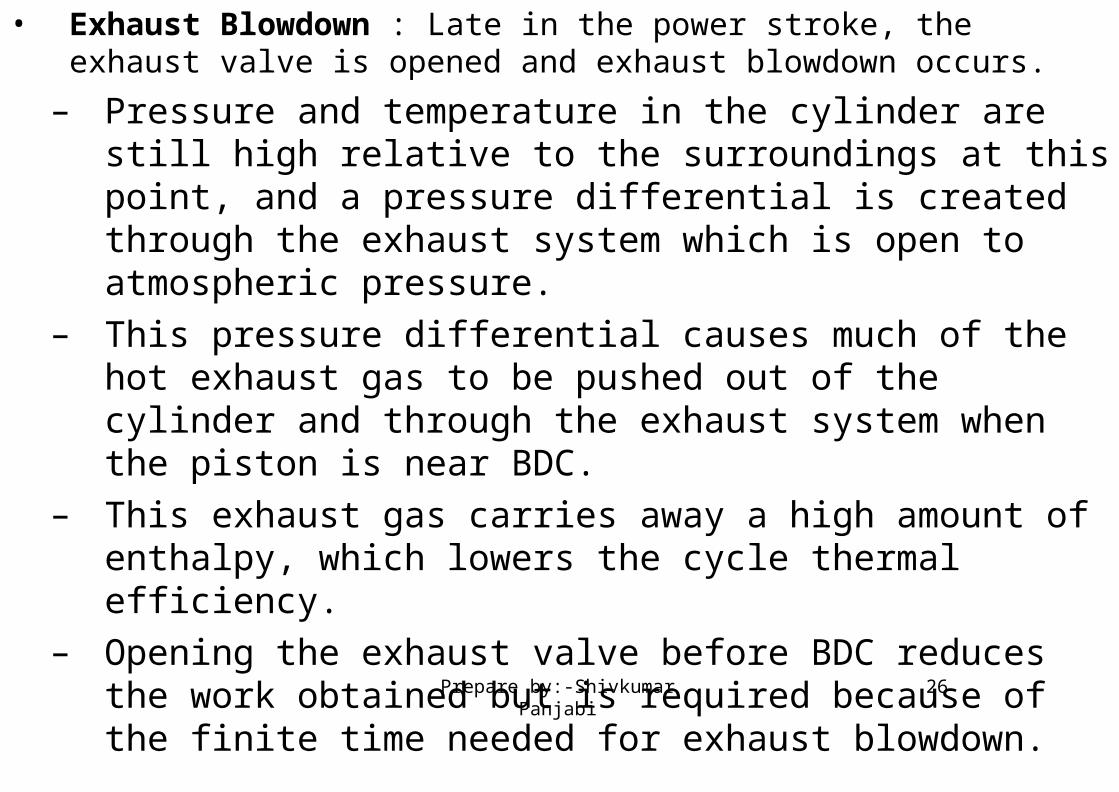
• Exhaust Blowdown : Late in the power stroke, the exhaust valve is opened and exhaust blowdown occurs.
– Pressure and temperature in the cylinder are still high relative to the surroundings at this point, and a pressure differential is created through the exhaust system which is open to atmospheric pressure.
– This pressure differential causes much of the hot exhaust gas to be pushed out of the cylinder and through the exhaust system when the piston is near BDC.
– This exhaust gas carries away a high amount of enthalpy, which lowers the cycle thermal efficiency.
– Opening the exhaust valve before BDC reduces the work obtained but is required because of the finite time needed for exhaust blowdown.
26Prepare by:-Shivkumar Panjabi

Figure7: Exhaust blowdown followed by Exhaust stroke27Prepare by:-Shivkumar Panjabi

• Exhaust stroke: By the time piston reaches BDC, exhaust blowdown is complete, but the cylinder is still full of exhaust gases at approximately atmospheric pressure.
– With the exhaust valve remaining open, the piston travels from BDC to TDC in the exhaust stroke.
– This pushes most of the remaining exhaust gases out of the cylinder into the exhaust system at about atmospheric pressure, leaving only that trapped in the clearance volume when the piston reaches TDC.
28Prepare by:-Shivkumar Panjabi
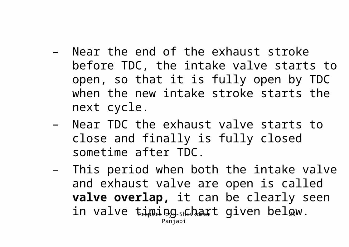
– Near the end of the exhaust stroke before TDC, the intake valve starts to open, so that it is fully open by TDC when the new intake stroke starts the next cycle.
– Near TDC the exhaust valve starts to close and finally is fully closed sometime after TDC.
– This period when both the intake valve and exhaust valve are open is called valve overlap, it can be clearly seen in valve timing chart given below.
29Prepare by:-Shivkumar Panjabi

Compression Ignition Engine :
• We will deal with Compression Ignition engine.
• The ideal diesel cycle PV diagram is shown in following figure 8.
30Prepare by:-Shivkumar Panjabi

Figure8: Ideal diesel cycle P-V Diagram.
31Prepare by:-Shivkumar Panjabi

Figure9: Four strokes of ideal Diesel cycle.
32Prepare by:-Shivkumar Panjabi
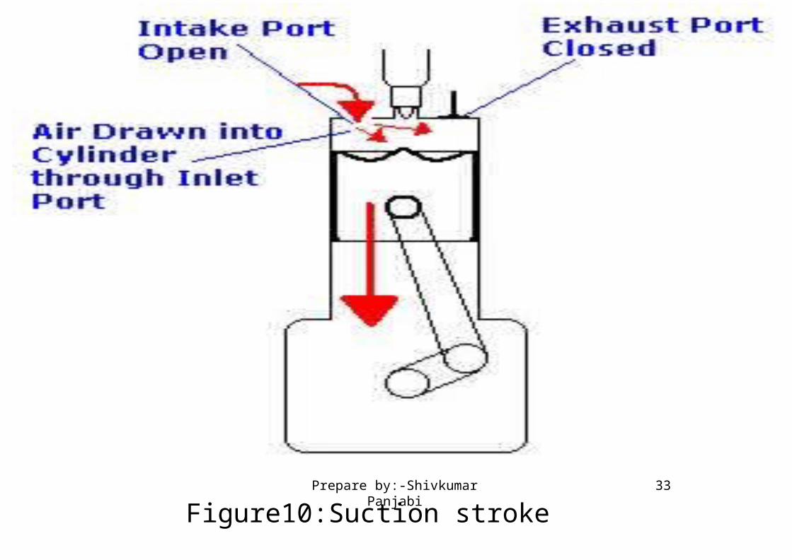
Figure10:Suction stroke33Prepare by:-Shivkumar Panjabi
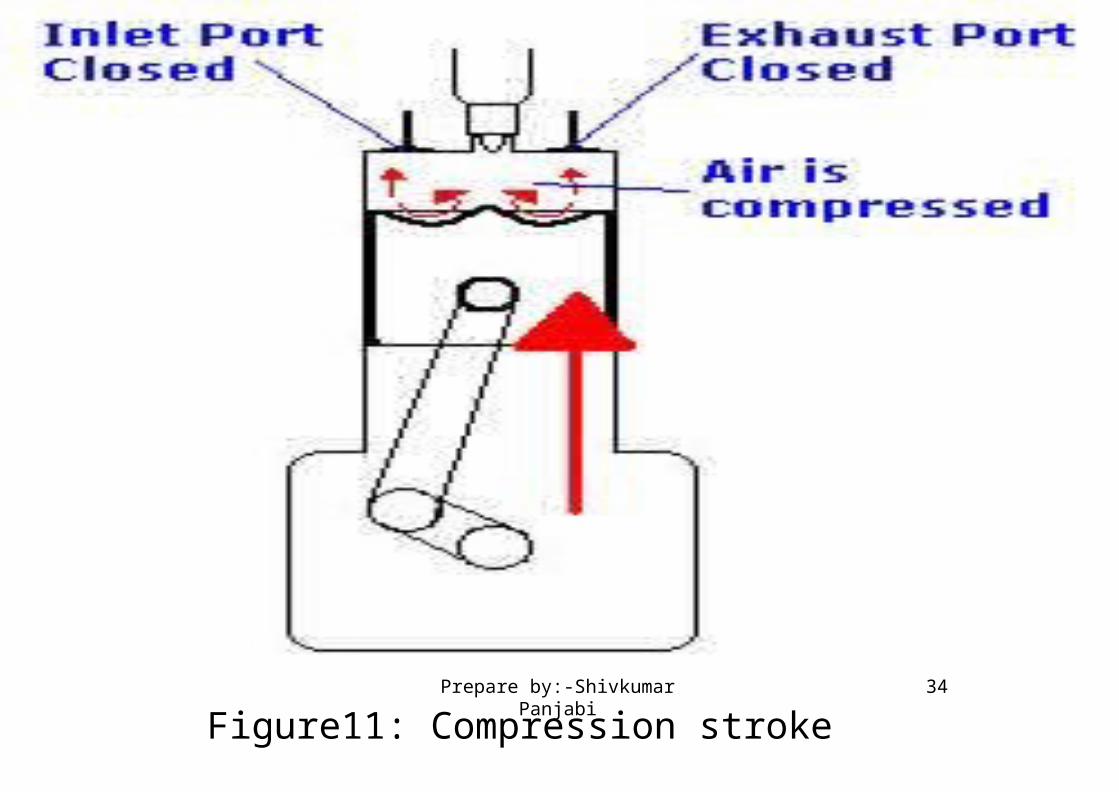
Figure11: Compression stroke34Prepare by:-Shivkumar Panjabi
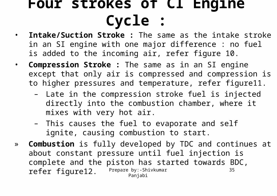
• Intake/Suction Stroke : The same as the intake stroke in an SI engine with one major difference : no fuel is added to the incoming air, refer figure 10.
• Compression Stroke : The same as in an SI engine except that only air is compressed and compression is to higher pressures and temperature, refer figure11.
– Late in the compression stroke fuel is injected directly into the combustion chamber, where it mixes with very hot air.
– This causes the fuel to evaporate and self ignite, causing combustion to start.
» Combustion is fully developed by TDC and continues at about constant pressure until fuel injection is complete and the piston has started towards BDC, refer figure12.
Four strokes of CI Engine Cycle :
35Prepare by:-Shivkumar Panjabi

Figure12:Fuel injection and combustion followed by Expansion stroke .36Prepare by:-Shivkumar Panjabi
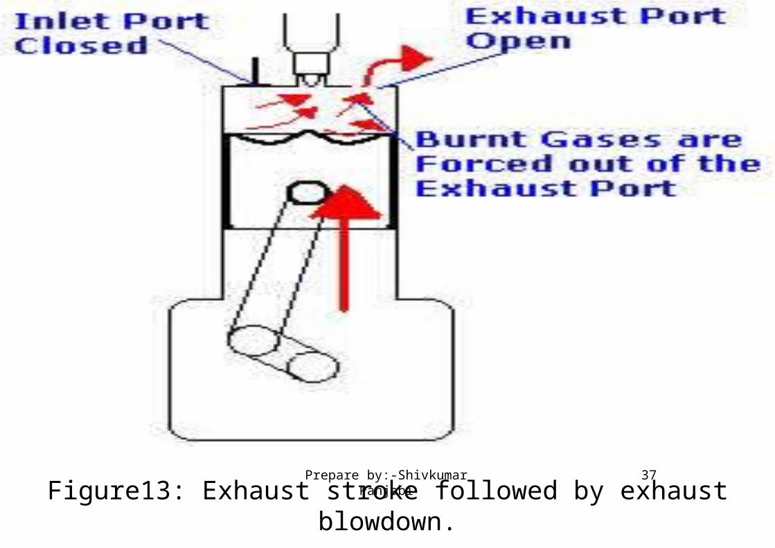
Figure13: Exhaust stroke followed by exhaust blowdown.37Prepare by:-Shivkumar Panjabi

• Expansion/Power stroke : The power stroke continues as combustion ends and the piston travels towards BDC, refer figure 12.
– Exhaust blowdown same as with an SI engine.
• Exhaust stroke : Same as with an SI engine, refer figure 13.
38Prepare by:-Shivkumar Panjabi
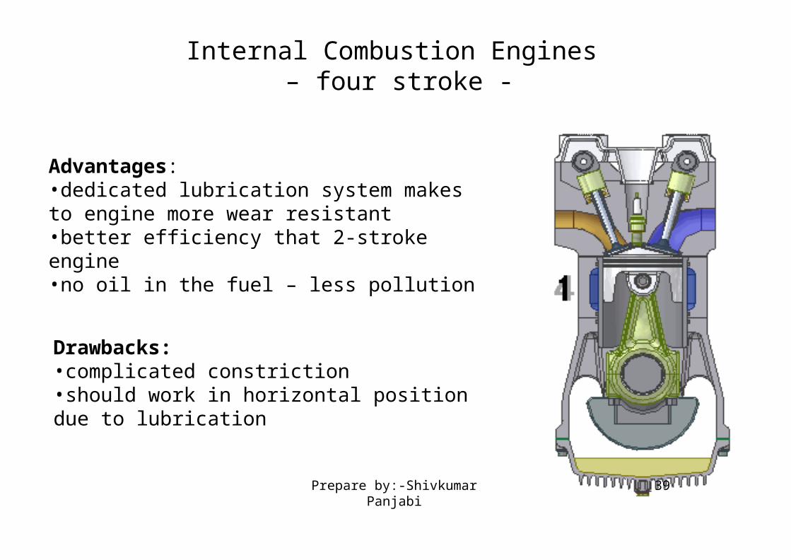
Internal Combustion Engines – four stroke -
Advantages:•dedicated lubrication system makes to engine more wear resistant•better efficiency that 2-stroke engine •no oil in the fuel – less pollution
Drawbacks:•complicated constriction •should work in horizontal position due to lubrication
39Prepare by:-Shivkumar Panjabi
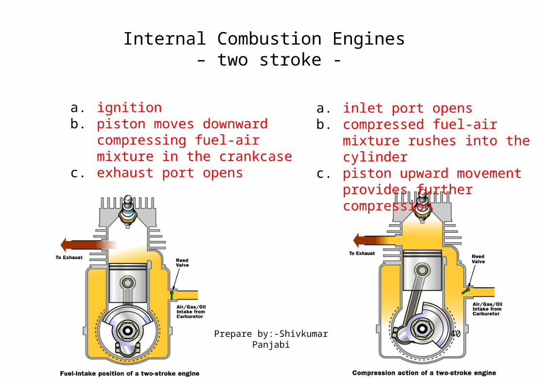
Internal Combustion Engines – two stroke -
1. Power / Exhaust 2. Intake / Compression
a. ignitionb. piston moves downward
compressing fuel-air mixture in the crankcase
c. exhaust port opens
a. inlet port opensb. compressed fuel-air mixture
rushes into the cylinderc. piston upward movement
provides further compression
40Prepare by:-Shivkumar Panjabi

Internal Combustion Engines – two stroke -
Advantages:•lack of valves, which simplifies construction and lowers weight•fire once every revolution, which gives a significant power boost •can work in any orientation•good power to weight ratio
Drawbacks:•lack of a dedicated lubrication system makes the engine to wear faster. •necessity of oil addition into the fuel •low efficiency •produce a lot of pollution
41Prepare by:-Shivkumar Panjabi

Thank you for your attention