I~ Bound... · application of this principle in pulse transformers for radar transmitters. Working...
13
·~ 28 PHILIPS TECHNICAL REVIEW VOLUME 19 PRE·MAGNETIZATION OF THE CORE OF A PULSE 'TRANSFORMER' BY MEANS OF FERROXDURE - by H. G. BRUIJNING and A. RADEMAKERS. 621.314.2.073.3:621.318. 124:621.374.3 Among the outstanding results yielded by recent solid-state research are ttv~ groups of pon-metallic magnetic materials, ferroxcube and ferroxdure, which have both been the subject of several articles in this Review. Eerroxcube is a soft magnetic material with low losses even at highfrequencies. Eerroxdure is a hard magnetic material, very suitablefor permanent magnets. A combinatio'n of the twomaterials isfound in ne!Cpulse transformers, developed for magnetron modulators. These transformers have a.ferroxcube core, which is pre-magnetized by a [erroxdure magnet. I' In electrical engincering and electronics we often find transformcrs whose primary or secondary current is entirely composed of pulses in the same direction. Some examples are: transformers feeding half-wave rectifiers" ignition coils for internal- combustion engines and'. the p~lse transformers feeding radar transmitters. The core of such trans- formers is unfavourably loaded: the magnetic induction, instead of ,oscillating between -Bmax and +Bmax, varies only between 0 and Bmax, so that one half of thc magnetization-curve is not used at all. There is a means, however, to employ both halves, viz. by pre-magnetizing the core. We shall demonstrate in the following that this can be success- fully effected by means of a ferroxdure permanent magnet 1). . In this article we shall confine ourselves to the application of this principle in pulse transformers for radar transmitters. Working principle of a radar transmitter A radar transmitter radiates periodically wave trains of large power and short duration. The peak power may be of the order of hundreds of kW, the duration of each wave train 1 [Lsec,and the repeti- tion frequency 1000 cis. In order to operate the oscillator tube (as a rule a magnetron) inter- mittently, it is fed with an anode voltage of approx- imately square waveform. • Fig. 1 shows a circuit of the type commonly' employed to generate such anode-voltage pulses. The thyratron Th being not ignited, the direct- . voltage' source E supplies a charging current flowing through the choke coil L, the pulse-shaping network P and the pulse transformer T. The pulse-shaping network P, which may be a lumped transmission line composed of coils and capacitors (delay line) 1) J. J. Welit, G. W. Rathenau, E. W. Gorter and G. W. van Oosterhout, Philips tech. Rev. 13, 194-208,1951/52. is thereby charged. The magnctron M is connected to the secondary winding of T. By igniting the thyratron, the .points A and C are suddenly short- circuitcd (short-circuiting of the D.C.-source is prevented by the choke L). T~is produces a square p .---------------- ---, A I I ~------~----~I~ : I I I I I I I ------- J 90195 Fig. 1. Circuit for supplying the anode-voltage pulses for a radar transmitter, E direct-voltage source. L choke coil. Th thyratron. I ignition device for the thyratron. P pulse- shaping network (delay line). T pulse transformer. NI magne- tron. voltage pulse across the primary of'pulsc transformer T, provided that the characteristic impedance of the delay line P is equal to the impedance between the p<?ints Band C. The duration of this pulse is equal to the time required by a w,ave front to travel through the network P and back again.' During this pulse the 'energy stored up in P is transferred, via the pulse transformer, to the magnetron and partly radiated as high-frequency' energy. At the end of each pulse the thyratron current falls to zer~ and the sequence can be repeated. The pulse tr~nsformer Frequency response Magnctrons handling large powers require a high voltage (several ten-thousands of volts). This is pro- duced by the pulse transformer T, which steps up a lower voltage supplied to the primary. A typical example: secondary 28 kV, 35 A; .primary 7 kV, 140 A (peak values).
Transcript of I~ Bound... · application of this principle in pulse transformers for radar transmitters. Working...

·~
28 PHILIPS TECHNICAL REVIEW VOLUME 19
PRE·MAGNETIZATION OF THE CORE OF A PULSE 'TRANSFORMER'BY MEANS OF FERROXDURE
-by H. G. BRUIJNING and A. RADEMAKERS. 621.314.2.073.3:621.318.
124:621.374.3
Among the outstanding results yielded by recent solid-state research are ttv~ groups ofpon-metallic magnetic materials, ferroxcube and ferroxdure, which have both been the subjectof several articles in this Review. Eerroxcube is a soft magnetic material with low losses even athighfrequencies. Eerroxdure is a hard magnetic material, very suitablefor permanent magnets.A combinatio'n of the two materials is found in ne!Cpulse transformers, developed for magnetronmodulators. These transformers have a.ferroxcube core, which is pre-magnetized by a[erroxduremagnet.
I'
In electrical engincering and electronics we oftenfind transformcrs whose primary or secondarycurrent is entirely composed of pulses in the samedirection. Some examples are: transformers feedinghalf-wave rectifiers" ignition coils for internal-combustion engines and'. the p~lse transformersfeeding radar transmitters. The core of such trans-formers is unfavourably loaded: the magneticinduction, instead of ,oscillating between -Bmaxand +Bmax, varies only between 0 and Bmax, sothat one half of thc magnetization-curve is not usedat all. There is a means, however, to employ bothhalves, viz. by pre-magnetizing the core. We shalldemonstrate in the following that this can be success-fully effected by means of a ferroxdure permanentmagnet 1). .
In this article we shall confine ourselves to theapplication of this principle in pulse transformersfor radar transmitters.
Working principle of a radar transmitter
A radar transmitter radiates periodically wavetrains of large power and short duration. The peakpower may be of the order of hundreds of kW, theduration of each wave train 1 [Lsec,and the repeti-tion frequency 1000 cis. In order to operate theoscillator tube (as a rule a magnetron) inter-mittently, it is fed with an anode voltage of approx-imately square waveform. •
Fig. 1 shows a circuit of the type commonly'employed to generate such anode-voltage pulses.The thyratron Th being not ignited, the direct-
. voltage' source E supplies a charging current flowingthrough the choke coilL, the pulse-shaping networkP and the pulse transformer T. The pulse-shapingnetwork P, which may be a lumped transmissionline composed of coils and capacitors (delay line)
1) J. J. Welit, G. W. Rathenau, E. W. Gorter and G. W. vanOosterhout, Philips tech. Rev. 13, 194-208,1951/52.
is thereby charged. The magnctron M is connectedto the secondary winding of T. By igniting thethyratron, the .points A and C are suddenly short-circuitcd (short-circuiting of the D.C.-source isprevented by the choke L). T~is produces a square
p.---------------- ---,A I I~------~----~I~ :
I II II I
I------- J
90195
Fig. 1. Circuit for supplying the anode-voltage pulses for aradar transmitter, E direct-voltage source. L choke coil.Th thyratron. I ignition device for the thyratron. P pulse-shaping network (delay line). T pulse transformer. NI magne-tron.
voltage pulse across the primary of'pulsc transformerT, provided that the characteristic impedance ofthe delay line P is equal to the impedance betweenthe p<?ints Band C. The duration of this pulse isequal to the time required by a w,ave front to travelthrough the network P and back again.' Duringthis pulse the 'energy stored up in P is transferred,via the pulse transformer, to the magnetron andpartly radiated as high-frequency' energy. At theend of each pulse the thyratron current falls tozer~ and the sequence can be repeated.
The pulse tr~nsformer
Frequency response
Magnctrons handling large powers require a highvoltage (several ten-thousands of volts). This is pro-duced by the pulse transformer T, which steps up alower voltage supplied to the primary. A typicalexample: secondary 28 kV, 35 A; .primary 7 kV,140 A (peak values).

1957f58, No. 1 PULSE TRANSFORMER WITH PRE-MAGNETIZATION 29
Fig. 2a shows the primary voltage VI as a functionof the time t, and fig. 2b the desired form of themagneti.c induction B in thetransformer core during
a t
-t
B
tb --r-~---------..dB
9019b _t
Fig. 2. a) Primary voltage Vl of the pulse transformer T in fig. 1,versus time t. b) Magnetie induction B in the transformer coreversus time.
the same period. The transformer must thereforetransfer as faithfully as possible the entire frequencyspectrum of VI; this spectrum is shown (for relativelyfar too wide pulses,jig. 3a) in fig. 3b. The frequency-response curve of the transformer, however, will'never be completely flat. Owing to the finite self-inductance of the primary, the induction B willnothave the form of flg. 2b, but there will be a loss at thelow frequency side, whilst the highest frequency thatis adequately transformed will be determined by therequired length of wire per turn. The frequency-response curve has, for example, a shape like thatshown in fig. 3e, with the result that the secondaryfrequency spectrum will be of the form shown infig. 3a. In the shape of the secondary voltage the lossof low-frequency components manifests itself as a"sa,gging" of the waveform (see fig. 3e and theoscillograms fig; 4) so that, in the wave train ,trans-mitted by the magnetron during a single pulse, thetransmitted power di.minishes accordingly. The lossof high-frequency components reduces the steepnessof the leading and trailing edges of the pulse, so thatthe tr~nsmitted .wave trains are less sharply de-fin~d. The first effect is more apparent if, for a giventransformer core, too few' windings have been used(self-inductance too low), and the s~cond effectpredominates if the total wire length and hence thenu:rn:berof turns is too large. A compromise is there-fore to, be sought.
Use of a ferroxeube core
The compromise attainable can be favourablyinfluenced by suitable choice of the core material. A,materialof high permeability i~ advantageous ill
.that it requires relatively fewer turns to give aspecified, self:inductance. ~ high saturation induc:tion is favourable in view of the small diameterrequired for the core (small length per turn andhence shorter total wire length). If at the same timethe eddy-current and hysteresis losses are low, thetransformer will have a high efficiency .. High permeability, low losses and' a not too lowsaturation induction are favourably combined incertain types of ferroxcube. From an engineeringpoint of view, ferroxcube has the advantage over ametai core in that the' former can be very easilycomposed' from a few solid blocks; for a metal coreonly rhin-rolled nickel-iron strip; wound into a ring,is suitable for this purpose. Ferroxcube moreovermakes it possible to give different parts of the mag-netic circuit different diameters, which is found tobe of great advantage with pulse transformers; a ring
]
'l't-
s ,'l'= 0.1 T nL----I T_';-t
20%
10
Q
d
n. 90700
Fig. '3. a) Rectangular pulses of duration. and repetition..frequency 1fT.. With a view to the clarity of figs. (b) and (d),the pulses are shownrelatively far too wide (.fT = 0.1 insteadof approx. 0.001). , . 'b) Spectrum ofthe pulse train (a). The amplitudes of the har-monics have .heen plotted vertically as a percentage of thepulse height; horizontally plotted are the order n and thefrequency f of the harmonics, for the case. = 10:-4 sec, T = ..10-:3 sec.c) Frequency response of a pulse transformer.d) Spectrum of the secondary voltage pulses.e) The secondary pulses are distorted owing to the shape ofcurve (c). .. . .(For the case of. = 10-6 sec, T = 10-3 sec, which is closer to 'normal radar usage, the scales of nand f should be multipliedby 100, and the linedensity in (b) and (d) should be IOOxgreater.)
< '
30 PHILIPS TECHNICAL REVIEW VOLUME 19
a b c
Fig. 4., Oscillograms of the secondary voltage of a pulse transformer whose prirnary voltageconsists of a series of nearly rectangular pulses (duration 1 [J.sec) and whose secondarywinding is resistance-loaded.a) Suitahle shape of secondary pulses.b) The too small primary self-induction causes a "sagging" pulse (loss of low-frequencyharmonics ).c) Too long a wire length reduces the steepness of leading and trailing edges (loss of high-frequency harmonics).
wound from metal strip must necessarily retain auniform diameter.
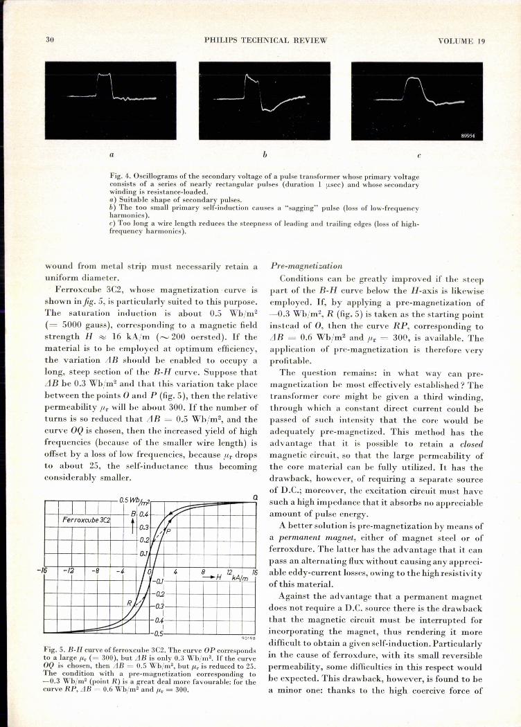
Ferroxcube 3C2, whose magnetization' curve isshown infig. 5, is particularly suited to this purpose.The saturation induction is about 0.5 Wb/rn2
(= 5000 gauss), corresponding to a magnetic fieldstrength H R>; 16 kAlm (,...._,200oersted). If thematerial is to be employed at optimum efficiency,the variation llB should be enabled to occupy along, steep section of the B-H curve. Suppose thatLlB be 0.3 Wb/m2 and that this variation take placebetween the points 0 and P (fig. 5), then the relativepermeability Ill' will be about 300. If the number ofturns is so reduced that llB = 0.5 Wh/m2, and thecurve OQ is chosen, then the increased yield of highfrequencies (because of the smaller wire length) isoffset by a loss of low frcquencies, because Ill' dropsto about 25, the self-inductance thus becomingconsiderably smaller.
OSWb ~f 0.4 »:V"'"Ferroxcube 3C2 /r/I 0.3 It, p
0.2
I0.1/ /
16 /2 -8 -4- Iq/ 4 B__.H 12 /6
II 0.11kA m
-I 0.2R Iv:V O.~
I--::::-V -0.4I
-0.5
Fig. 5. B-H curve offerroxcuhe 3C2. The curve OP correspondsto a large /-lr (= 300), but LIB is only 0.3 Wh/m2. If the curveOQ is chosen, then LIB = 0.5 Wh/mz, but /-lr is reduced to 25.The condition with a pre-màgnetization corresponding to-0.3 Wh/m2 (point R) is a great deal more favourahle: for thecurve RP, LIB = 0.6 Wh/mz and /-lr = 300.
a
Pre-magnetizationConditions can be greatly improved if the steep
part of the B-I-I curve below the I-I-axis is likewiseemployed. If, by applying a pre-magnetization of-0.3 Wb/m2, R (fig. 5) is taken as the starting pointinstead of 0, then the curve RP, corresponding tollB = 0.6 Wb/m2 and Ilr = 300, is avai.lable. Theapplication of pre-magnetization is therefore veryprofitable.
The question remains: in what way can pre-magnetization be most effectively established? Thetransformer core might be given a third winding,through which a constant direct current could bepassed of such intensity that the core would beadequately pre-magnetized. This method has theadvantage that it is possible to retain a closedmagnetic circuit, so that the large permeability ofthe core material can be fully utilized. It has thedrawback, however, of requiring a separatc sourceof D.C.; moreover, the excitation circuit must havesuch a high impedance that it absorbs no appreciableamount of pulse energy.A better solution is pre-magnetization by means of
a permanent magnet, either of magnet steel or offerroxdure. The latter has the advantage that it canpass an alternating flux without causing any appreci-able eddy-current losses, owing to the high resistivityof this material.Against the advantage that a permanent magnet
does not require a D.C. source there is the drawbackthat the magnetic circuit must be interrupted forincorporating the magnet, thus rendering it moredifficult to obtain a given self-induction. Particularlyin the cause of ferroxdure, with its small reversiblepermeability, some difficulties in this respect wouldhe expected. This drawback, however, is found to bea minor one: thanks to the high coercive force of
QQ1Q8

1957/58, No. 1 PULSE TRANSFORMER wrra PRE-MAGNETIZATION' 31
ferroxdure, a thin slab of this ~aterial is sufficient,so that the air-gap to be made in the transformercóre can be narrow ;'nd consequently the decreasein self-induction remains moderate. Wè shall returnto this l~ter in this article. Let us first examine howthe ferroxdure reacts to a current pulse through ,the transformer.
Behaviour of ferroxdure subjected to a pulse-shapeddemagnetising field '
, First of all we shall consider the general case of apulse transformer with a core, pre-magnetized by a•steel permanent magnet, The B-H curve of magnetsteel is represented infig. 6. The initial condition ofthe magnet is characterized by a point o~ the part ofthe B-H curve in the second quadrant, e.g. point 1.
B
t
Fig. 6. B-H curve of a magnet steel. 1-0-4 working line of amagnet made ofthis steel, pre-magnetizing a pulse transformer.1 initial working point. During a pulse the flux is reversed andpoint 2 is reached. At the end of the pulse, point 3 becomes thenew working point. The .pre-magnetization has thus taken onthe wrong polarity. '
If now the transformer is operated by a pulse of such'amplitude and direction that it changes the sign ofihe induction, then the condition of the magnet will, be temporarily represènted by the'point 2, whichlies equally far below the H-axis .as 1 lies above it.The aim is obviously to have the initial conditionresto~ed after the' pulse, but it will be readilyappreciated that this is by no means cert~in. As soonas the pulse disappears, the working point traversesthe line from."2 to 3; the terminal point 3. beingsituated on the "working line" 1-0-4 ofthe system 2).The line 2-3 has only a slight upwards slant (the
2) Further in 'this article the working line will be more fullyexplained. See also A. Th. van Urk, Philips tech. Rev. 5,29-35, 1940.
"reversible pérmeability" of the magnetic material'[,so that 3 may he very well sitU:atedbelo:WthèH-axis.This would mean that the pre-magnetisation had .not only' changed its value, but alsö taken on thewrong sign, which, of course, h~s to be prevented aiall costs. ' . . . ' .With ferroxdure, however, matters are quite
different. 'I'hereversible permeability offerroxdure Iis only little less than the slope of the È-H curve, sothat the return curve lies closely along and nearlyparallel with the B-H curve. The induction of thematerial, moreover, can' be given a considerablenegative value without the risk of losing themagnetization on the return path. An' idealizedrepresentation of ,this behaviour, which we shallinitially use in the reasoning which follows, is showninfig·7.Approximated by straight lines, the magnetiza-
tion J of ferroxdure I is plotted against H in fig. 7a.With increasing intensity of the demagnetizingfield, J remains constant as long as H does notexceed the value JHc, but when H does exceed thisvalue, J is entirely reversed. Fig. 7b shows the'corresponding B-H curve; B = J + f1-oH, in which!-lo is the permeability of free space (= 4n X·10-7Wb/Am). When f1-oH is plotted as abscissa on thes~me scale as B, as is done in fig. 7b, then the line~
"
a
tI-'-'_' f-.-.--
0
Pof~ pJi
.~"
-
Fig. 7. a) Magnetization J, and (b) induction B of ferroxdure, asfunctions of f.loH (idealized). The value of J is shown-as thedotted line in (b). The chain-dotted lines in both figures applyto a less strongly magnetized ferroxdure.
run at an angle of 450• Only the upper slanting line
is of interest to us here, It intersecte the f1-oH-axisat a point J.loBHc (which, in ferroxdure, has a valuesignificantly different from f1-oJHc): The working'point can be shifted up and down alongrhe uppersloping line of fig. 7b in a completely reversiblemanner. A condition of weaker magnetization isrepresented in both diagrams by a chain-dotted line,which may likewise b~ reversibly followed, andfor which the same limiting value JHc of thedemagnetizing field applies.,
--I~~--------~--~--~ - -~./
32 PHILIPS TECHNICAL REVIEW
. It. should be -ohserved that in this idealized These two. factors fairly well define the criticalpicture the relative permeability /Lr= 1, whereas condition where the risk o.fpermanent demagnetiza-the actual value for ferroxdure lies between 1.1 and _ tio.n has to. be seriously considered, It may be added1.4. We shall deal with the actual B-Hcurve later in heré that; in practice, operatien near this criticallimit
is not advisable. In case of certain faults the backflux may assume values considerably above normal,so. that a certain safety margin is always necessary.
The faults in question are those whereby themagnetron fails t~ oscillate, The pulse transformerwill than operate virtually without load and theearlier merrtioned ' condition that" the delay line(P, fig. 1) should be in series with a resistanceequalling its own characteristic' impedance is nolonger fulfilled. As a result of this, the magnetizingcurrent becomes many times (c.g. 40 X) greaterthan normal. Fortunately, owing to. the resultingsaturation of the ferroxcube, the induction Bkin the core increases at a far lower rate than theeurrent; however, the induction rises to. the extentthat a safety factor of 2-3 is indispensable to. avoiddemagnetizatio.n of the ferroxdure, This safety'factor is defined as (LlBk)max/2Bo, (LlBk)max beingthe maximum change in Bk that does not yet causeany demagnetization .
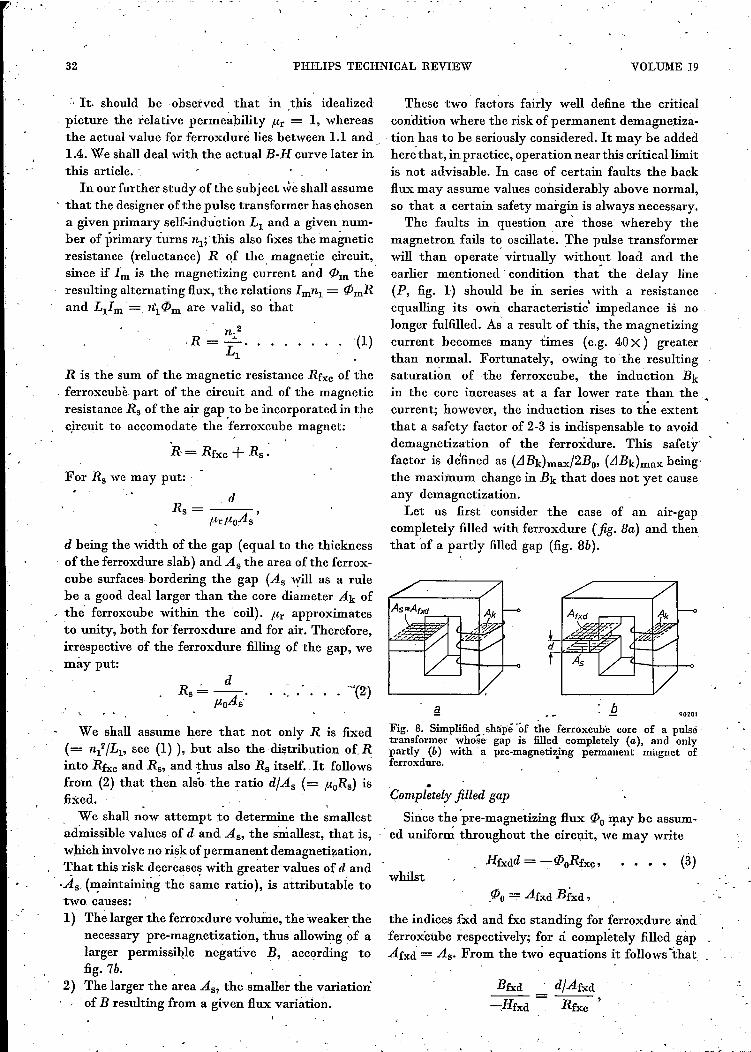
Let us first consider the case of an air-gapcompletely filled with ferroxdure (fig. Ba) and thenthat of a partly filled gap (fig. 8b).
this article. 'In our further study of the subject ,ve shall assume
. that the designer of the pulse nransformer has chosena given primary self-induction Ll and a given num-ber of primary turns nl; 'this also. fixes the magneticresistance (reluctance) R of the magnetic circuit,since if Im is the magnetizing cu~rent m~d ({Jm the'resulting alternating flux, the relations Imnl = ({JmRand c,Im '= n'l ({Jm are valid, so. that
n;_2.R=- .....
Ll
R is the sum of the magnetic resistance Rfxc o.f the, ferroxcubè part of the circuit and of the magneticresistance Rs of the air gap .to.be inoorporated in thecircuit to. aceomedate the ferroxcuhe magnet:
, .R= Rfxc + Rs.
For Rs we may put: '
. dRs = ,
/LrfloAs
d being the width of the gap (equal to. the thicknessof the ferroxdure slab) and As the area of the ferrox-cube surfaces bordering the gap (As will as a rulebe a go.o.ddeallarger than the core diameter Ak ofthe ferroxcuhe within the 'coil]. fl'r approximatesto. unity, both for 'ferroxdure and for air. Therefo.re,irrespective of the ferroxdure :filling of the gap, we
_ may put:
We shall assume here that not only R is fixed(= nl/Ll, see (1) ), but also. the distrihution of Rinto. Rfxc and Rs, and thus also. Rs ftself .. It fo.llo.w;from (2) that then also the ratio. d/As (= floRs) isfixed. . ,. We shall no.wattempt to. determine the smallestadmissible values of d and As, the smallest, that is,which involve no risk o.fpermanent demagnetizatio.n.~hat this risk decreases with greater values of d and.As [maintaining the same ratio], is attributable to.two. causes:1) The larger the ferroxdure volume, the weaker the
necessary pre-magnetization, thus allowing of alarger permissible negative B, ,acco.rding to.fig.7b.
2) The larger the area As? the smaller the variation'.of B resulting from a given flux variation.
(1)
VOLUME 19
Fig. 8. Simplifiedshliifé'óf the ferroxcube core of a pulsetransformer whosé gap is filled completely (a), and onlypartly (b) with a pre-magnetizjng permanent magnet offerroxdure.
Çornpl;tely filled gap
Since the 'pre-magnetizing flux ({Jo:!pay be assum-ed unifo.r~ throughout the circuit, we may write
whilst({Jo- Ahd Bfxd ,
the indices fxd and fxc standing for ferroxdure andferroxcube respectively; for á completely filled gapAfxd = As. From the two equations it follows "that
Bfxd---=-:,Hfxd
'_
d/Afxd
Rfxc '

, \
1957/58, No. 1 PULSE TRANSFORMER WITH PRE-MAGNETIZATION, ' . 33
or, according to (2),
Bfxd e,-PoHfxd - Rfxc'
,~hich latter ratio, by assumption, is known.In the ideali~ed B-H curve of ferroxdure (fig~ 9),
equation (4,) is represented by the straight line 0-1(the working line). This line should be independentof the choice of d and As as long the ratio d/As iskept constant. ' ,
The interscction of the working line and the B-Hcurve defines the working point of the ferroxdure
4-
oPoH
67 90202
Fig. 9. 1-2-7 is part of the B-PoH curve of strongly magnetizedferroxdure, 3-4-7 the same for a more weakly magnetized fer-'roxdure, and 5-6-7 for a still more weakly magnetized ferrox-dure. 0-1 working line of a ferroxdure magnet incorporated in amagnetic circuit. Wor.king point 1is impracticable (safety factorless than 1),3 represents the critical case (safety factor = 1),, a~d 5 permits a safety factor = 2. '
,,'
when the transformer is currentless. The. threeparallellines in fig. 9 are applicable to three differenttransformer sizes. Let us first choose d and As suchthat completely magnetized ferroxdure is necessaryto produce the desired flux (/Jo in the currentlesstransformer. This is the flux that brings out about aninduction of 0.3 Wb/m2 in the ferroxcube core and isrepresented by the point R in, fig. 5. The workingpoint would be situated at 1 (fig. 9). It is evidentthat if the flux is reversed; a point 2 would be passed,the latter being situated less below the horizontal'axis' than I, lies above it. This case, therefore,cannot be used, and we have to increase As and d.and use less strongly magnetized ferroxdure. If this
(4)
is continued until the B value corresponding topoint 3 is just adequate to produce the desired flux(/Jo, 'we arrive at the critical condition (safety',factor 1): if the flux- is reversed point 4 is reached;which lies equally far from the axis as 3.
In practice, however, a certain safety margin isrequired, which is provided by choosing point 5 asworking point. If the flux is reversedv S' becomes the
, working point (the ordinate 0.£ 5 is Bo, that of 5' is-Bo)' The reverse flux is now allowed to assumesuch a value that the. point 6 ,with ordinate -3Bois reached, the safety factor being the ratio of thelength 5-6,to the length 5-5', which is 2.The procedure for deterinining the dimensions d
and As is now a simple one. The pre-magnetizingflux needed to produce the desired pre-induotienBo (= 0.3 Wb/m2 in fig. 5) in the core is (/Jo= AkBo'Let Bw be the ordinate of the working point;corresponding to a sufficiently large safety factor(such as point 5 in fig. 9), then the required cross-section Afxd for the ferroxdure is given by:
Afxd = (/Jo/Bw = Ak Bo/Bw·
"
From this cross-section, by means of eq. (2), we findthe necessary thickness d of the ferroxdure slab(this being also the width of the gap).
Partly filled gap
On the. foregoing theoretical considerations wehave arrived at a workable design for a transformerwith a gap completely filled with incompletelymagnetized ferroxdure (fig. 8a). The question now'à,rises·whether it is also possible (and perhaps better)to use a gap partly filled (fig. 8b) with more stronglymagnetized ferroxdure. We find that the latter casecan be easily related to the foregoing as follows.If we reduce the cross-section of the filling in a
given gap (Afxd < As, :fig.8b), then obviously the.magnetization of the ferroxdure must be raised to .such an extent that the flux (/Jo through the coreremains the same. This means that -the magneticpotential difference between the boundary planes, ofthe gap, (/JoRfxc,must retain the same value.T t follows'from (3), therefore, that Hfxd must not changeeither. By analogy, we can also demonstrate that
,,'under conditions of reversed flux the value of Hfxd ', must remain the same. Let. a-b in fig. 10 be theearlier mentioned working line for a completely filledgap',-then the working line for a gap appropriatelyfilled with completely magnetized ferroxdure will becod, which lies parallel to and vertically above e-b.,The corresponding, change in induction LlB is henceequally large .in either case, since an equal fluxvariation 2(/Jo is evenly distributed throughout the

34 PHILlPS TECHNICAL REVIEW VOLUME 19
gap, irrespective of what portion of the gap is takenup by air and what by ferroxdure (both being hereassumed to have f-lr = 1); in either case the clÎangeLIB will be 2fPo/As.
8
t82
II1I
I "1/
/~" ~~
~B
I /I /I /I '":/
e
90203
Fig. 10. o-b working line of a ferroxdure magnet completelyfilling the gap of the pulse transformer; remanence BI' If thegap is partly filled with more strongly magnetized ferroxdure(remanence B2), the working line becomes cod, situatedvertically above a-b and along the characteristic B21, whichruns parallel with Bç-e. The change in induction LlB as well asthe safety factor is the same in either case (at least in theseidealized curves).
-;
We further notice that the maximum ~rangethrough which B can travel without causingpermanent demagnetization likewise .remain~ un- .altered: accordi.ngly the safety factor (ae/ab = cf/cdin fig. 10) is also unaltered. The two cases depicted'here are completely equivalent. Later we shall see,
. however, when the actual B-H curve is substitutedf~r the idealized straight-line representation used upto now, that designs usingthe completely filled gapare to be preferred.
The question now arises to what extent, the gaphas to be filled' with more strongly magnetizedferroxdure; in other words what must be the ratioa = Afxd/As?, The equivalence of the two cases considered infig. 10 is a result of the fact that the only relevantfactor .in this question (the ratio Rs/Rf~e beingsupposed constant) is the short-circuit flux of theferroxdure, AfxdBrem, irrespective of the manner inwhich the gap is filled, Therefore, when a core withcompletely filled gap is modified into one with a gap .partly filled with more strcngly magnetisedmaterial,
it is essenrial to keep AfxdBrem= aAsBrem constant.When changing over from a-b to c-d in fig. 10, we
must choose a= Bl/B2 (As not being changed), andfor intermediate cases, where the remanence is Brem,the working line will as a rule lie between the verticaldotted lines, provided that a and Brem are so chosenthat aBrem = Bl'
This concludes our genera!" theoretical treatmentof the subject. We shall now consider the actual B-Hcurve and find out to what extent our conclusions,have to be modified.
Actual B- H curve of ferroxdure
Fig. lla shows the B-P,oH curve measured onferroxdure 1. The part we are primarily concernedwith is represented on an enlarged scale in fig. llb,together with the reversible characteristics forBrem = 0.20 and 0.12 Wb/m2.
In the foHowing we shall retain ~ constant ratioRslRfxe, which we shall assume to be unity (Rs= Rfxe= t R), which was found to be a convenient valuein practice. For a completely filled gap (a = 1),accordingto eq. (4), the working line in the B-f-loHdiagram will run at an angle of 450
•
Let us examine what possibilities these twoconditions ofmagnetization may offer. With Brem = .0.20 Wb/m2, we find the working point 1, whereBfxd = 0.08 Wb/m2. In order to produce the desiredpre-induetion Bo = 0.30 Wb/m2 in the core, we musttherefore choose As = (0.30/0.08)'l'1k = 3.8 Ak'We find, however, from fig. llb that the intersec~ion2 with the B-H curve lies less below the axis than 1lies above it, so that reversing the polarity is notpermissible. This is also manifest from the fact thatthe safety factor is less than 1, the value for (LlB)maxin ferroxdure reading 0.13 Wb/m2 in the diagram, sothat the safety factor is as low as 0.13/(2 X 0.08) ~
. 0.8. . ' ,
The weaker pre-magnetization Brem = 0.12Wb/m2 gives a far better result. The working linebecomes 3-3' in fig. llb, with the value Bfxd =0.05 Wb/m2 in point 3, so that As must become(0.30/0.05)Ak ':;= 6 Ak. The required quantity offerroxdure, therefore, is (6/3.8)2 = 2.5 fimes thatin the previous example (both the cross-section Asand the thickness d increase by a' factor of 6/3.8,their rati~ being constant according to (2) ). Thislarger amount of material results in a remarkableimprovement ofthe safety factor. This factor, ~eingthe ratio of the length of 3-4 to that of 3-3', nowbecomes 2.5, which may be ,considered adequate.
We now have a workable design with weakly.magnetized ferroxdure filling the entire air-gap.

1957/58, No. 1 . PULSE TRANSFORMER WITH PRE-MAGNETIZATION - 35
,8
t
/0.2Wb/m
Ferroxdore I
0.7
. /Wb/m2-O.5 -0.4. -0·3 ~OV -0.1 0 -PoH
-/ -0.1
0.2
I / .0.3.~
/VG.4V
I / -0.5
t1/-0.6V ,
~.
0.7
8
t
013
-O.l?Wb/mz
p.Fig.1!. a)B-poH curvemeasured on ferroxduret b) Part of (a)enlarged, with the reversible characteristics for Brem = 0.12and 0.20 Wb/m2, and the working lines for a = 1 and 0.5.Working point 1 cannot be used (safety factor less than 1). Thecurve 3-3' corresponds to working point 3, 5-5' corresponds to5,~and 6-6' to 6. -
From this, wc might now change over to a partialfillingwith stronger magnetic material, in the manner
e . described earlier by shifting the working-line 3-3'vertically upward, whilst appropriately varying the 'value of a., We may, however, also approach the matterdifferently again, viz. by assigning a fixed value« 1) to ~ and then investigating the possibilities,thus offered. We shall do so for a = 0.5 incombination with the values Brem = 0.12 and0.20 Wb/m2.Let us start by finding the working line for the
currentless condition. For a half-filled gap we mustreplace Rs in the numerator of (4) by the magneticresistance of the half gap, viz. 2Rs (= 2Rfxc); thedenominator contains the magnetic equivalentresistance of the ferroxcube core shunted by theempty half of the gap: Rfxc in parallel with 2Rs =Rfxc in parallel with 2Rfxc = .~Rfxc' The slope ofthe working line for a = 0.5 (see fig. lIb) is there-fore tan y = 2Rfxc/(!Rfxc) = 3. This working lineintersects the two reversible characteristics in thepoints 5 and 6.' In order to evaluate the induction Boin the ferroxcube core, the flux through the emptyhalf of the gap (induction BI) must be subtractedfrom the flux produced by the ferroxdure. In theempty half H equals Hfxd. We may therefore write: ' , "
90204
in which BI and Hfxd are negative and have váluesthat can be read from fig. lIb. This permits us toé\rahiat~' the ratio As/Ak necessary to produce thepre-induetion Bo = 0.30 Wb/m2. Thus we find thevalues As/Ak = 6.7 for point 5 and As/Ak' 12 fórpoint 6. "I'he working points for the reverse flux -which we must know for determining the safety, factor - can be fou~d by substituting the abovevalues of As/Ak and Bo in (5). For the two casesconsidered here we arrive at the conditions
B +{loIl _:_-0.09 and -0.05 Wb/m2 respectively,
Q0205
corresponding to the points 5' and 6' in fig. lIb. The. safety factor can now be read from the diagram: itamounts to (5-2)/(5-5')- = 1.8 for the material withBrem -:- 0.20 Wb/m2, and to (6-4)/(6-6') = 5.0 forthat with Brem = 0.12 Wb/m2. .
In Table I, finally, we can summarize the casesdealt with in this section. For each of the four casesconsidered, are given the values of As/Ak, the short-circuit flux aBremAs ofthe ferroxdure divided by Ak,the required volume offerroxdure (as a percentage),and the safety factor: '.

36 PHILIPS TECHNICAL REVIEW VOLUME 19
Table I. Characteristic quantities relating to a pulse trans-former core, pre-magnetized with ferroxdure I, for valuesof Brem = 0.12 and 0.20 Wb/m2 and for a completely-filledgap (a = 1) and for a half-filled gap (a = 0.5), Rs beingequal to Rfxc.
AsjAk 6.0 3.8 12 6.7aBremAsjAk (Whjm2) 0.72 0.74 0.72 0.67Volume of ferroxdure (%) 260 100 530 160Safety factor 2.5 0.8 5.0 1.8
Row 1 of the table shows that As/Ak is alwaysfairly large, so that the ferroxcube surfaces in theair-gap must be substantially larger than the corediameter within the coil. This leads, as we shall seepresently, to constructions different from thoseshown in fig. 8.
On page 34, on the strength of the idealizedcharacteristic and on the assumption that flr = 1for ferroxdure, we have said that the short-circuitflux o.A sBrem of the ferroxdure must he heldconstant. The actual values of this flux (dividcd bythe constant cross-section Ak) as given in row 2 ofthe table, are indeed found to he fairly constantfor the actual characteristic as well.
Rows 3 and 4 show the surprising result that thesafety factor in the region considered is roughlyproportional to the ferroxdure volume, and inde-pendent of its shape and state of magnetization(a. and Brem). Itwill, therefore, always be preferableto use a completely filled gap, since the ferroxcubeyoke on either side of the gap can then have thesmallest diameter, whereas on the other hand thesaving in ferroxdure by using a partially filled gap isnot worth mentioning. Ofthe four cases shown in 'the,table that of column 1 is preferable for this reason.If a larger safety factor, e.g. 5, is required, it shouldbe possible with a. = 1 to arrive at a better designthan that of column 3. Owing to the inadequatesafety factor, the case of column 2 cannot be used,whilst that of column 4 has a somewhat low safetyfactor and is, moreover, in view of a. < 1, by nomeans the best solution.
Example of an actual design
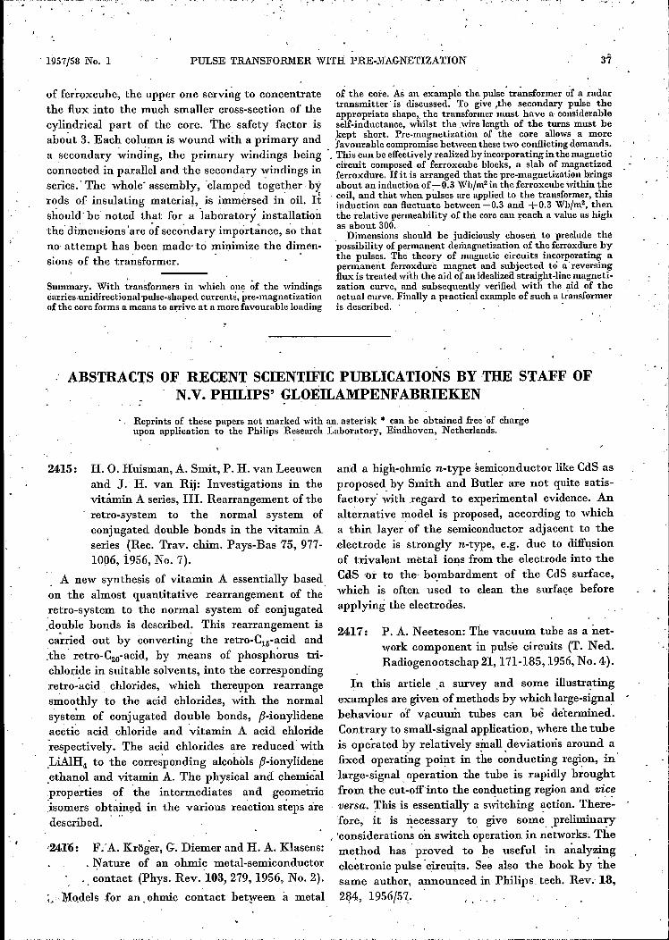
Finally, as an example we shall describe a pulsetransformer operating in a laboratory set-up fortesting magnetrons. The primary demands for thistransformer were that it should produce a sec-ondary pulse of the appropriate shape and thatit should retain its pre-magnetization under allconditions.Fig. 12 is a photograph of the core and the essen-
tial data are given in the caption. The completely
filled gap is 2 mm wide and has an area As = 8 X 10= 80 cm", i.e. 8 X larger than the cross-section ofthe cylindrical cores. This large ratio As/Ak, to-gether with thc wish to use ferroxcube blocks of
89953Fig. 12. Core of the pulse transformer of a testing instalJationfor magnetrons. Principal dirnensions: base 100 X 170 mm,height 162 mm. Further principle data:
Primary Secondary
Peak voltagePeak currentImpedance .Number of turns .Pulse duration. .Rise time ....Cross-section Ak within coilArea As of gap.Width d of gapSafety factor
7 kV140 A50 016
28 kV35 A
800 Q66fLsec
0.14. fLsec10 cm2
80 cm2
2 mmapprox. 3.
standardized dimensions, have led to the shapedepicted here.The two vertical columns consist of ferroxcube
3C2 discs of 10 mm thickness (thicker discs aredifficult to manufacture without cracks) and 36 mmdiameter. The yokes are formed by rectangularblocks of ferroxcube 4B2, which can easily be manu-factured in large pieces; if necessary, the somewhatsmaller permeability can he compensated by givingthe yokes a larger cross-section. Pre-magnetizationis effected by eight 2X 20 X 50 mm slabs of ferrox-dure I, magnetized in the direction of their thick-ness. These are interposed between two large slabs
of the core. As an example the. pulse' tr~nsformer <if a radartransmitter is' discussed. To give ,the secondary pulse theappropriate shape" the transformer must have a considerableself-inductance, whilst the wire length of the turns must beJ-ept short. Pre-magnetization of the core allows a more
. favourable compromisebetween these two conflicting demands., Tills can be effectivelyrealized by incorporating in the magneticcircni't composed of ferroxcube blocks, a slab of magnetizedferroxdure. If it is arranged that the pre-magnetization bringsabout all induction of ;-0.3 Wb/rn2in the ferroxcube within thecoil, and that when pulses are applied to the transformer, thisinduction can fluctuate between -0.3 and +0.3 Wb/m2, thenthe relative permeability of the core can reach a value-as highas about 300.Dimensions should he judiciously chosen to preclude the
possibility of permanent demagnetization of the ferroxdure bythe. pulses. The theory of magnetic circuits incorporating apermanent ferroxdure magnet and subjected tel areversingflux is treated with the aid of an idealizedstraight-line magneti-zation curve, and subsequently verified with the aid of theactual curve. Finally a practical example of such a transformeris described. '
1957/58 No. 1 PULSE TRANSFORMER WITH PRE"MAGNETIZATION
, "
ABSTRACTS OF. RECENT SCIENTIFIC PUBLICATIONS BY THE STAFF OFN.V. PHILIPS' GLOEILAMPENFABRIEKEN
Reprints of these papers not marked with an, asterisk • can be obtained freeof chargeupon application to the Philips Research Laboratory, Eindhoven, Netherlands.
of ferroxcuhe, the upper one serving to concentratethe flux into the much smaller cross-section of thecylindrical part of the core. The safety factor. isabo~t 3. Each column is wound with a primary anda secondary winding, the primary windings beingconnected in parallel and the secondary windings inseries.' The whole' assembly, 'clamped together byrods of insulating material, is immersed in' oil. Itshould ~be noted that for a iaboratory installationthe' dimeusions 'are ~f secondary importance, s'o th~tno attempt has been made-to minimize the dimén-sions of the tra~sformer.· '
Summary, With transformers in which one ~f the windingscarries,unidirectional'pulse-shaped currents', pre-magnetizationof the core forms a means to arrive at a more favourable loading
2415: H. O. Huisman, A. Smit, P. H. van Leeuwenand J. H. van Rij: Investigations in thevitamin A series, Ill. Rearrangement of theretro-system to the normal system ofconjugated double bonds in the vitamin Aseries (Rec. Trav. chim. Pays-Bas 75, 977-1006, i956, No. 7).
A new synthesis of vitamin A essentially based,on the almost quantitative rearrangement of the.retro-system to the normal system of conjugated.double bonds is described. This rearrangement isca;"ried out by converting the retro-Cjg-acid and.the retro-C2o-acid, by means of phosphorus tri-chloride in suitable solvents, into the corresponding.retro_'acid chlorides, which thereupon rearrangesmoothly to the acid chlorides, with the normalsystem of conjugated double bonds, tJ-ionylideneacetic acid chloride and 'vitamin A acid chloriderespectively. The acid chlorides are reduced' with.LiAlH4 to the corresponding alcohols tJ-ionylidene.ethanol and vitamin A. The physical and chemicalproperties of the intermediates and geometric'isomers obtained in the various reaction steps aredescribed.
'24I6: F.'A. Kröger, G. Diemer and H. A. Klasens:. Nature of an ohmic metal-semiconductor, contact (Phys. Rev. 103.,279,1956, No. 2).
;, .l\:[o,dels for an. ohmic contact between a metal
and a high-ohmic n-type semiconductor like CdS asproposed, by Smith and Butler are not quite saris-factory' with regard to experimental evidence. Analt~rnative model is proposed, according to whicha thin layer of the semiconductor adjacent to the.electrode is strongly n-type, e.g. due to diffusionof trivalent metal ions from the electrode into theCelS -or to the' bombardment of the CdS surface,which is often used to clean the surface beforeapplying the electrodes.
2417: P. A. Neeteson: The vacuum tube as a net-work component in pulse circuits (T. Ned.Radiogenootschap 21,171-185,1956, No. 4).
In this article .a survey and some illustratingexamples are given of methods by which large-signalbehaviour of vacuum tubes can bè determined,Contrary to small-signal application, where the tubeis operated by relatively small deviatieris around a:fixed operating point in the conducting region, inlarge-signal. operation the tube is rapidly broughtfrom the cut-offinto the conducting region and vi.c~versa. This is essentially a switching ~ction. There-'fore, it is necessary to give some preliminary
, 'consideration~ on switch operatien in networks. Themethod has' proved to be useful in analyzingelettronic pulse 'circuhs. See also the book by thesame author, a~nounced in Philips tech. Rev: 18,284, 1956/5~. . ' , ,

38 PHILIPS TECHNICAL REVIEW VOLUME 19;
"
2418: 'Á. van Wieringen and N. Warmoltz: On thepermeation of -hydrogen and helium in singlecrystal silicon and germanium at elevatedtemperatures (Physica 22, 849-865, 1956,
, No. 10).
A mass spectrometer examination of the permea-bility of the elements silicon and germanium to thegases hydrogen and helium has been carried outin the temperature range 96771207°C for siliconand 766-930 °Cfor germanium. Using certain crystalgrowing and cutting techniques, two kinds of dif-fusion ce~s' were made byeach of which it waspossible to determine both diffusion coefficient andsolubility as well asthe activation energies of diffusionand solution from non-steady-state permeation meas-ur~~ents. No permeation of the gasesneon, argon andnitrogen could be detected. It seems that hydrogenin silicon can ,occur in a readily-diffusible form andalsoin a state in which it is less mobile. The readily-diffusible form consists (If atoms or protons.
2419: N. W. H. Addink: Spectrochemical analysisby means of the D.C. carbon are (Appl.Spectroscopy 10, 128-137, 1956, No. 3).
A complete description of the constant tempera-ture are method of quantitative analysis whichhas been developed in Eindhoven is given, withtables of the empirically determined K.-valuesreported so that they can he checked in otherlaboratories. The method consists of completelyvolatilizing 5 mg of a powdered sample in a shal-low anodic crater of a carbon are, with the additionof materials to modify the rate .of volatilizàtion ifrequired. The line intensities ,are calibrated andcorrections are made by comparison with selectedFe lines, originating from a "standard light so~ce;'so as ,to get comparable analytical results; thecalculatioi:ts 'reqmred are illustrated by severalexamples, ·whl.ch indicate the relative 'accuracy ofthe method to he approximately 10%.
2420: K. Compaan and y. Haven: Correlationfactors for diffusion in' s~lids (Trans. FaradaySoc. 52, 786-801, June 1956, No. 6).
, ,
The relation of Einstein D = B~T/e, relating thediffusivity and mobility of particles [ions or atoms),'must be modified for the case of diffusion ~n solids,if a vacancy mechanism holds, because there willhe a correlation hetween successive steps of a par-ticle, even if the steps of the vacancies themselvesare uncorrelated, Certain' symmetry conditionsbeing fulfilled, the relation of Einstein must bemodified by a correlation factor '
f = (1 + COS#i,i+1)/ (1 ., cos -èi,i+1) , (1)
where 'l?i,i+1 is the angle between two successivesteps of a particle. The diffusion problem can hetranslated into the theory of electrical networksand with the help of measurements in a resistornetwork the value of cos Oi,i+1 is easily evaluated.This has been done for several types of lattices.Other cases, where eq. (1) does not hold, because oflack of symmetry, are' treated by similar methods.Appropriate substitutions having been made, thediffusion ofassociated pairs has been treated as thediffusion of a single particle in a so-called transposedlattice.
2421: C. M. van der Burgtn Les transducteurspiézomagnétiqties à noyau massif de ferrite(Commun. Congrès international sur lestraitements par les ultra-sons, Marseille23-28 May .1955; published 1956).
Interim report on some of the results of an inves-tigation into the use of ferroxcube materials forpiezomagnetic vibrators. A fuller account hasmeanwhile appeared in this Review: Philips tech.Rev. 18, 285-298, 1956/57, (No. 10).
2422: R. Vermeulen: Stereo reverberation (IRETransactions on Audio, AU-4, 98-105, 1956,No.4).
Reproduetion of the article published in Philipstech. Rev. 17, 258-266, 1955/56.
. '
2423: H. J. Oskam: High-frequency gas-dischargebreakdown in neon-argon mixtures (J. appl.Phys. 27, 848-853, 1956, No. 8).
, Breakdown electric fields in a waveguide at afrequency of 9500 Mc/s are presented for a number ofneon-argon mixtures at various pressures. The argonpercentage is found to have a large influence on thebreakdown electric field, just as Penning found forthe D.C. discharge. For each argon concentration,only one minimum is found in the curves givingbreakdown field as a function of pressure. Thisresult contrasts with the two minima found in theD.C. discharge for some neon-argon mixtures. Thiscan bé explained. by the gïfference between theefficiency of energy transfer from the electric fieldto the electrons in the D.C. case and the 'high-frequency case. The relation between the coneen-tration'· of argon and the breakdown fields is dis-cussed. The influence of electric field distortionsand the standing-wave ~atio ~n the waveguide areinvestigated.
24~4: W. L. Wanmaker: Contribution à la chimiedes halophosphates de calcium '(J. Phys,Radium ~7, 636-640, 1956, No. 8-9).
Detailed study of the secondary reactions during
-,

1957/58, No. 1 ABSTRACTS OF RECENT: SCIENTIFIC PUBLICATIONS 39
the preparation of calcium. halophosphates activatedby Sb3+, or by Sb3+ and Mn2+, in order to' suppressthe formation of Sbs+ or Mn3+. ions, or of freeSb203 and Mn304, the effect of which is to lowerthe quantum efficiency.
2425: J. L. Ouweltjes: Quelques considérations surla transmission d' énergie dans les halophos-phates (J. Phys. Ràdium 17,641-644, 1956,No; 8-9). '
Measurements have been made of the brightnessof halophosphates activated by Sb and Mn, and ofthe killer effect of iron. The energy transfers be-tween activator, sensitizer and killer ions are dis-cussed. Possibly the greatest part; of the killereffect of iron is a mere absorption.
2426: W. Ch. van Geel: Sur la luminescence decouches d'oxydes formées par oxydationélectrolytique (J. Phys. Radium 17, 714-717,1956, No. 8-9) ..
Measurements of the Iuminescence. L producedduring the formation of layers obtained by anodicoxidation give L = aI(ebd -1); I current density,d thickness of the layer. When A.C. tension is applied,,light flashes are observed at each change of polarity.
2427: P. Zalm: Sur l'électroluminescence du sulfurede zinc (effet Destriau) (J. Phys. Radium 17,777-782, 1956, No. 8-9).
A discussion is given of the voltage and tempera-ture dependence of the emittance of an electrolu-minescent phosphor. The emittance (H) ~ voltage(V) relation is given by H =Ho exp (_bjV1
/.). Thevariation of the emittance with temperature de-pends on the relation between the local field in thephosphor particles and the applied field, the tem-perature dependence being described by the varia-tion of b with, temperature.
2428: J. H. Stuy: Studies on the mechanism ofradiation inactivation of micro-organisms,Il. Photoreactivation of some bacilli andof the spores of, two Bacillus cereus strains. (Biochim. biophys, Acta 22, 238-240, 1956,No.2).
In order to find out whether bacilli in generalcould be reactivated by light after ultraviolet in-activation, several' different species have beenInvestigated. About half of them did not show anyphotoreactivation (PHR) while ~ome of themshowed a moderate PHR. Only two B. cereus strainscould be photoreactivated very easily. The con-clusion is drawn that PHR is not so generallyoccurring among the bacilli, but under' e.ntirely
different conditions there might be some reactiva-tion. The spores of the B. cereus strains mentioned,above did not show PHR. This was not due to theirlack of water, since "germinated spores" behavedsimilarly' in this respect. Germination of the sporeswas carried out in a synthetic medium. which per~mitted a transformation of the spore_sinto a follow-ing stage only. During this t~an:sformation solidsare exchanged for water from the medium, causinga considerable increase of the water content.
2429': j..-H .. Stuy: Studies on the mechanism ofradiation inactivation of micro-organisms,
. Ill. Inactivation of germinating spores of,Bacillus cercus (Biochim. biophys. Acta 22,241-246, 1956, Nó. 2).·
Upon incubation in a germination'medium, restingspores of Bacillus cereus lost their resistance againstheat, X-rays and ultraviolet radiation. These phen-omena were studied in detail using a syntheticgermination medium which permitted a transfer-m~tion of the spores into a following stage' only.The results showed that the loss in resistanceagainst heating at 70°C for 10 minutes was veryrapid. The loss of resistance against X-rays followedroughly the same .rate, The UV-resistance of thespores, however, increased considerably during thefirst minute of incubation; thereafter, it rapidly felloff. Apart from the UV-increase in the, first minute,the simultaneous loss of the three resistances studiedsuggests that this loss is due to one mechanism.,In this respect the water uptake by the spores isconsidered.
2430: H. B. Haanstra: Einige Bemerkungen überdie Polystyrol-SiO-Abdr~ck.method~ (Rev.universelle Mines 99, 481-485, 1956, No. 10).(Remarks on the polystyrol-SiO, replicateohnique; in German.) , .
The examination of electron micrographs obtain-ed using the polystyrene-SiO technique shows thatthe thickness of the SiO layer is not uniform. ~singthis idea, the author explains that certain zones'of the replica ~hich were not perpendicular to thedirection of the. heam, will appear much clearerthan 'others in transmission.
·2431: J. B. de, Boer and W. Morass: Berechnungder Sehweite aus der Lichtverteilung vonAutomobilscheinwerfern (Lichttechnik 8"433-437, 1956, No.10). (Calculation ofthevisibility range from the light distributionof car headlamps; in German.)
V. J. Jehu has derived a partly experimental,
PHILIPS T;E,<;HN:ICAL REVIEW
partly' theoretica] method for calculating the visi-. bility range in the light of car headlamps of which. the light distribution is known. Allowance is madefor dazzle by oncoming' cars. The results, however,are not always in agreement with observation, Theauthors-have therefore-made extensive newmeasure-ments of visibility under road conditions. With thehelp .of the results the visibility can be derivedgraphically. Comparisons between the quality ofcar headlamps can then be made very simply,~nowi~g their light' distribution. '
R 310: C. M.' van der Burgt: Controlled crystalanisotropy and controlled temperature de-pendence of the permeability and elasticityof various cobalt-substituted ferrites (Phi- ,lips Res. Rep. 12,97-122, 1957, No. 2).
Dynamic elasticity at remanence, piezomagneticcoupling at rem:anence, and initial permeability ofpolycrystalline toroids of various cobalt-substitutedferrites are determined in the temperature rangefrom ~ 196 oe to + 120°C (and higher). Thecompositions are represented approximately by(Ml_yZnY)1....xCoxFe204'where M stands-for one ofthedi"valent metal ions (Li~+Fe:+), Ni2+,órMn2+. Theiirst-ordermagnetocrystalline anisotropy constant Klof cobalt .ferrite is known to be large and positi~e(2 to 3 X 10⁵ J Jm3). Consequently the incorporationof a small amount of cobalt ferrite in solid solutionin other ferrites that have Kl < 0 (ferrous, nickel,manganese ferrites, and presumably lithium ferrites)leads to a compensation of crystal anisotropy at atransition temperature To depending on the amountof cobalt ferrite. At room temperature the compen-sating effect of cobalt substitutions in ferrous ferriteis nearly 4 times as strong as expected from- simple
. linear interpolation. On the other hand cobalt sub-stitutions in manganese ferrite appear to be lesseffective than expected, the compensating amountof-cobalt being about 4 times that expected. Never-theless the curves To vs: x for all systems of cobalt-suhstituted :mixed ferrites have, a similar shape.The fact that the crystal anisotropy passes throughzero' at a temperature To implies tliat around thistemperature only strain anisotropy and pore-shapeanisotropy remain, so that there exists a .smalltemperat-.;tre range where the substance is magneti-cally .and magnetoelastically soft. The resulting'peaks in the permeability and compliance, together,with . the overall increase' of these quantities'with temperature, lead- to temperature rangessome-where above To where the permeability andthe elasticity are substantially temperature-inde-pendent.
) yOLUME 19
R 311: K. S. Knol: A thermal noise standard formicrowaves (Philips Res. Rep. 12, 123-126,1957, No. 2). '
A therIIial noise source for the 3-cm waveband,consisting of a heated platinum waveguide terminat-ed with a ceramic wedge, is described. The tempera-~ure óf the wedge is fixed at the melting-point ofgold. With this noise source as a standard, thenoise temperature of the Philips noise source K50Ais determined to be 21700 "K, with an accuracy ofabout 5 per cent.
R 312: J. van den Boomgaard and K. Schol: Thep: T-x phase diagrams of the systems In-As,Ga-As and In-P .(Philips Res. Rep. 12,127-140, 1957, No. 2).
For the compounds In-As, Ga-As and In-P thephase relations solid-liquid-vapour have been deter-mined .. In-As has a maximum melting-point of943 ± 3 °C at an arsenic pressure of 0.33 atm.Ga-As has a maximum melting-point of 1237 ± 3.~Cat an arsenic pressure of 0.9 atm. For In-P the maxi-mum melting-point is estimated to lie at 1062± 7°Cat a phosphorus pressure of approximately 60 atm.
R 313: J. L. H. Jonker and Z. van Gelder: Theinternal resistance of a radio-frequencypentode (Philips Res. Rep. 12, 141-175,1957, No. 2).
Besides the direct electrostatic influence of theanode potential upon the cathode current, which issmall in radio-frequency 'pentodes, the authorsinvestigate the effects causing the current distri-bution between screen grid and anode due to re-flection of electrons by the suppressor-grid wiresand by the anode (secondary emission). The extraspace charge in the cathode space, due to thesereflected electrons, is taken into account. The re-flected electrons are also distributed between anodeand screen 'grid, as a result of the same effects. Aconvergent series therefore originates for the anodecurrent, the derivative daIJdVa of which gives thereciprocal value of the internal resistance. To obtaina high value of the internal resistance; the reflectioncoefficient of the suppressor grid must. be small,which can be obtained by taking a very small valuefor the' ratio between the wire diameter and thepitch of this grid: The effective potenrial- of thesuppressor grid; however, must be kept low: The;calculated values of the internal resistance of radio-,frequency pentodes are about 40% higher than themeasured opes, which, in view of the large number,of effects playing a 'part, must be considered as asatisfactory result.