:i’ -A .Design Procedure for a Tensio ” Stiffened Truss-Column · NASA CR 3273 c.1 -- NASA...
36
NASA CR 3273 c.1 -- NASA Contractor Report 3273 . :i’ -A .Design Procedure for a Tensio ” Stiffened Truss-Column William H. Greene CONTRACT NAS1-16000 APRIL 1980 https://ntrs.nasa.gov/search.jsp?R=19800014247 2018-07-31T17:32:46+00:00Z
Transcript of :i’ -A .Design Procedure for a Tensio ” Stiffened Truss-Column · NASA CR 3273 c.1 -- NASA...

NASA CR 3273 c.1
--
NASA Contractor Report 3273
.
:i’ -A .Design Procedure for a Tensio ” Stiffened Truss-Column
William H. Greene
CONTRACT NAS1-16000 APRIL 1980
https://ntrs.nasa.gov/search.jsp?R=19800014247 2018-07-31T17:32:46+00:00Z

TECHLlBRARYKAFB,NY
NASA Contractor Report 3273
A Design Procedure for a Tension-Wire Stiffened Truss-Column
William H. Greene Kentrou Interrratioual, hr. Hampton, Virginia
Prepared for Langley Research Center under Contract NAS l- 16000
National Aeronautics and Space Administration
Scientific and Technical information Office
1980
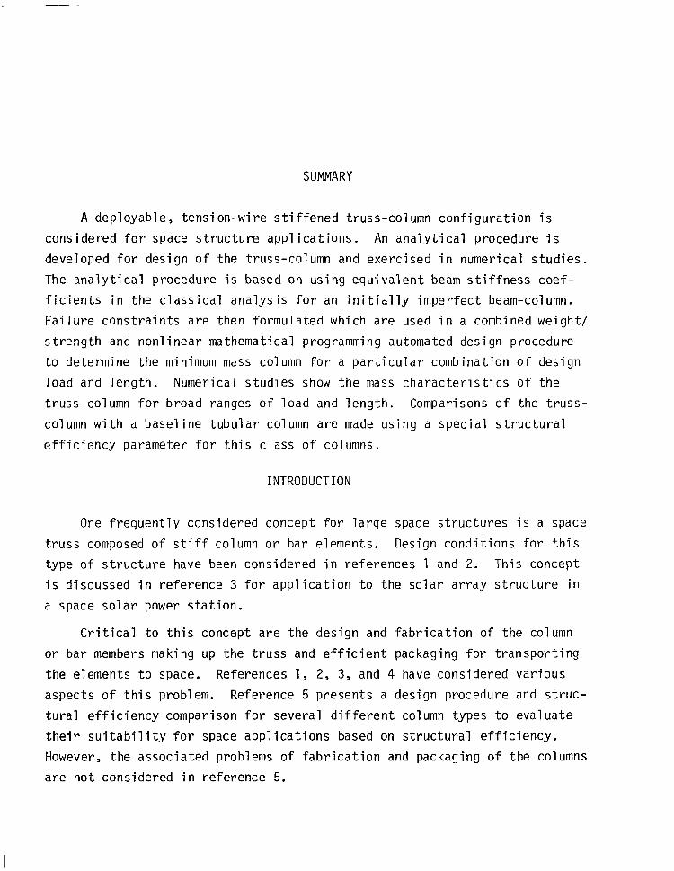
SUMMARY
A deployable, tension-wire stiffened truss-column configuration is
considered for space structure applications. An analytical procedure is
developed for design of the truss-column and exercised in numerical studies.
The analytical procedure is based on using equivalent beam stiffness coef-
ficients in the classical analysis for an initially imperfect beam-column.
Failure constraints are then formulated which are used in a combined weight/
strength and nonlinear mathematical programming automated design procedure
to determine the minimum mass column for a particular combination of design
load and length. Numerical studies show the mass characteristics of the
truss-column for broad ranges of load and length. Comparisons of the truss-
column with a baseline tubular column are made using a special structural
efficiency parameter for this class of columns.
INTRODUCTION
One frequently considered concept for large space structures is a space
truss composed of stiff column or bar elements. Design conditions for this
type of structure have been considered in references 1 and 2. This concept
is discussed in reference 3 for application to the solar array structure in
a space solar power station.
Critical to this concept are the design and fabrication of the column
or bar members making up the truss and efficient packaging for transporting
the elements to space. References 1, 2, 3, and 4 have considered various
aspects of this problem. Reference 5 presents a design procedure and struc-
tural efficiency comparison for several different column types to evaluate
their suitability for space applications based on structural efficiency.
However, the associated problems of fabrication and packaging of the columns
are not considered in reference 5.

Because of the large size of many of the space systems being consid-
ered, both the length and diameter of the individual component members must
be large to create an efficient structure. This large size for the column
element makes complete fabrication to the structural state on Earth and
subsequent transportation to space impractical. Thus fabrication and pack-
aging of a column concept become at least as important as structural effic-
iency and probably more so.
Two basic fabrication/packaging concepts have received most of the
attention in studies of large space systems. In one approach, the primary
structural columns are assembled on orbit from Earth fabricated, nestable
tapered columns (refs. 2 and 4). It has been shown in these references
that, because of the nesting of the column half elements, high packing densi-
ties can be achieved. In addition, the tapered columns can be assembled
into large primary columns that have good structural efficiency. The draw-
back of this method is that the on-orbit assembly is highly labor intensive
requiring automation for the large systems. In the second approach, raw
material stock (either aluminum or composites) is transported along with a
fabrication machine to space, where the actual fabrication takes place
(refs. 3 and 6). Although both structurally efficient members and high
packing densities can be achieved with this approach, the added complexity
of on-orbit fabrication is a significant drawback.
An alternative to these concepts is a deployable primary column
which is fabricated, tested, and packaged on Earth and then transported
into space
minimum of
ing assemb 1
operations
The column is then expanded to its structural state with a
operations on orbit. This approach eliminates the time consum-
y of many smaller components and minimizes the complicated
in space associated with on-orbit fabrication. The problems
of a dep
(1)
loyable column concept are:
The difficulty of designing a collapsable structure whose
deployed length and possibly width are large compared
with the launch vehicle.
(2)
2
Maintaining high structural efficiency so that the overall
mass that must be transported to space is low.

(3) Packaging the structure appropriately to achieve mass
critical payloads in the launch vehicle.
In this study, attention is focused on problem (2). A tension-wire
stiffened truss-column design, that was previously described in reference 7,
is considered herein. Reference 7 presented results from a structural
efficiency and packaging study of the column. Presented herein, are:
(a) A description of the load carrying mechanisms and structural
behavior of the column.
(b) An analytical and design procedure for the column.
(c) A number of numerical studies which characterize the column
design for a broad range of lengths and applied axial loadings.
SYMBOLS
A,, AC, A,, Ad cross sectional areas of longerons, center column, spokes,
and diagonals
a maximum amplitude of sinusoidal imperfection
C axial stiffness for the truss-column defined in
equation A-l
cS transverse shear stiffness for the truss-column
defined in equation A-4
D bending stiffness for the truss-column defined
in equation A-3
Young's modulus of the longerons, center column,
spokes, and diagonals
Gi
IC
failure constraints on the design of the truss-column
moment of inertia of the center column
L column length
M column mass; also bending moment (equation A-5)
3

MJ
M max
n
P
'des
pE
pIP pIc
'd
pS
R
r min
r sol,min
T
Q LJ
V
V max
X
A
17
multiplier to account for the mass of the joints
in the truss column
maximum bending moment induced in the column
by an imperfection
number of bays in a truss-column
applied axial compressive load in the column
design load for the column (assumed compressive)
Euler buckling load for the column (equation A-6)
initial forces in the longerons and center column
axial component of the diagonal load at any
column cross section
load induced in a spoke by the diagonals
radius of truss-column cross section (see figure 2)
cross sectional radii of longerons, center column,
spokes, and diagonals
minimum allowable tube radius for spokes and center column
minimum allowable solid radius for members
initial tension in the diagonals
wall thickness of center column and spokes
transverse shear force induced by an imperfection
maximum value of the transverse shear force
column axial coordinate
axial end shortening of the column
ratio of longeron stiffness to center column
stiffness defined in equation A-21
4

total complementary potential energy of the
column
0 diagonal angle defined in figure 2
E column neutral axis strain
K column curvature
material density of longerons, diagonals,
center column and spokes
DESCRIPTION OF THE TENSION WIRE
STIFFENED TRUSS-COLUMN
A model of a four bay section of a tension wire stiffened truss-column
in its deployed state is shown in figure 1. A hinge joint or joints would
be present along the center column in an actual structure to allow the
packaged column to be folded to fit in the cargo area of the launch vehicle.
In the analysis presented, a very simple butt hinge is postulated which will
transmit compressive forces in the center column but not tensile forces. The
requirement that the center column not be carrying a tensile load when the
overall truss-column is under tension is prescribed as a design condition.
The tension-wire stiffened truss-column discussed herein is composed
of four types of members:
(1) The center column runs along the centroidal axis of the equilat-
eral triangular cross section and carries the compressive forces
induced by applying initial tension to the longeron members plus
a part of any axial loading applied to the truss-column.
(2) The three longeron members at the vertices of the triangular
cross section are under an initial tensile load. These provide
all of the truss column's bending stiffness and part of the
axial stiffness until one or more of the three longerons become
"slack" due to an applied compressive load to the column.

(3)
(4)
The three sets of diagonal members in each bay of the truss-column
are also capable of carrying only tension. These provide all of
the transverse shear stiffness of the truss column until the
shear load reaches a value that causes the diagonals to become
"slack". Actually, under a shear load, some of the diagonals
tend to lose tension and some become more stressed; however, a
significant loss of transverse shear stiffness results when any
of the diagonal members become slack.
Three spokes are placed at intervals (the bay length) along the
center column, and in the deployed state, run radially from the
center column to the longerons. When the truss-column is com-
pacted, the hinges at each end of the spoke allow the spoke to
fold flat against the center column. At the same time, the long-
erons collapse onto the center column to drastically reduce the
radius of the truss. The spokes serve to maintain the cross
sectional shape, to support the center column at intervals, and
also to induce a uniform tension in the diagonal members.
From figure 1 it can be seen that one of the interior spokes at each
set is slightly buckled. This buckled spoke acts as a constant force
spring which regulates the tension in the diagonal members. Thus, when
the column is deployed and the spokes buckle, a uniform tension, related
to the buckling load of the spoke, is induced in the diagonals. If the
spokes remained rigid during deployment, the tension in the diagonals would
be highly dependent on the exact length of the diagonal and due to manufac-
turing tolerances would vary from bay to bay. The design criteria for the
internal spokes, then, is that their buckling load induce the necessary
tension in the diagonals. The exterior spokes (three at each end of the
column) can not buckle since they carry a vertical component of load from
the longerons sloping to the center column. These three spokes at each end
are designed specially.
6

ANALYSIS AND DESIGN PROCEDURE
The design of the wire-stiffened expandable truss-column is made mOre
difficult because (1) certain considerations have to be made to allow the
structure to deploy reliably and (2) since it is a pre-tensioned structure,
the values of the initial forces must be selected and have an important
influence on the remainder of the design. The approach used to analyze the
truss-column is very similar to that used in reference 5 with the above two
factors included. In reference 5 the importance of considering the effects
of an imperfection in the column design was demonstrated. An imperfection
or bow in the column has two primary implications. First, the imperfection
causes a bending moment to be induced in the truss-column due to an axial
load which tends to overload one of the longerons. Second, the imperfection
causes a transverse shear force to be induced in the truss-column which must
be carried by the diagonal members. This induced transverse shear force
determines the amount of initial tension required in the diagonal members.
The analysis of the truss-column is based on determining a set of
equivalent beam properties for the truss and using these in an imperfect
column analysis (see ref. 8) to predict the overall loads and deformations.
Then the forces in the individual members (center column, longerons, spokes,
and diagonals) can be calculated and used to determine expressions for differ-
ent failure modes. This analysis procedure is derived in detail in Appendix A.
Based on this analysis the design of the truss-column is accomplished
by a combination of classical weight-strength methods and direct minimization
of the truss mass to yield the minimum mass structure. The design load, Pdes,
the column length, L, the wall thickness of the tubular center column and
spokes, and the diagonal angle, 8, (see fig. 2) were assumed to be known.
Although the tubular member wall thicknesses could also be selected in the
design process, experience has shown that for these lightly loaded columns,
wall thicknesses tend to be selected at a minimum gage due to manufacturing
constraints. Specific values taken for wall thicknesses are listed in the
numerical results section. For manufacturing convenience, the diagonal
angle, 8, was also kept constant in the optimization process; however, the
7
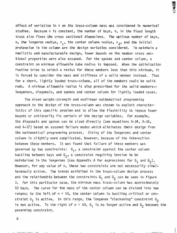
effect of variation in 0 on the truss-column mass was considered in numerical
studies. Because 8 is constant, the number of bays, n, in the fixed length
truss also fixes the cross sectional dimensions. The optimum number of bays,
n, the longeron radius, rR, the center column radius, rd, and the initial
pretension in the column are the design variables considered. To maintain a
realistic and manufacturable design, lower bounds on the member cross sec-
tional properties were also assumed. For the spokes and center column, a
constraint on minimum allowable tube radius is imposed. When the optimization
routine tries to select a radius for these members less than this minimum, it
is forced to consider the mass and stiffness of a solid member instead. Thus
for a short, lightly loaded truss-column, all of the members could be solid
rods. A minimum allowable radius is also prescribed for the solid members--
longerons, diagonals, and spokes and center column for lightly loaded cases.
The mixed weight-strength and nonlinear mathematical programming
approach to the design of the truss-column was chosen to exploit character-
istics of this specific problem and to allow the flexibility to impose lower
bounds or arbitrarily fix certain of the design variables. For example,
the diagonals and spokes can be sized directly (see equations A-34, A-36,
and A-37) based on assumed failure modes which eliminates their design from
the mathematical programming process. Sizing of the longerons and center
column is slightly more complicated, however, because of the interaction
between these members. It was found that failure of these members was
governed by two constraints: Gl, a constraint against the center column
buckling between bays and G2, a constraint requiring tension to be
maintained in the longerons (see Appendix A for expressions for Gl and G2). a However, for any value of n, these two constraints are not necessarily simul-
taneously active. The trends exhibited in the truss-column design process
and the relationship between the constraints Gl and G2 can be seen in figure
3. For this particular case, the minimum mass truss-column has approximately
50 bays. The curve for the mass of the center column can be divided into two
ranges; to the left of n = 50, the center column is buckling critical or con-
straint G 1 is active. In this range, the longeron "slackening" constraint G2
is not active. To the right of n = 50, Gl is no longer active and G2 becomes the
governing constraint.
8

It is obvious that for the optimum number of bays, n = 50, both con-
straints are active which is characteristic of a weight-strength design.
However, in general, two other considerations are important:
(1) In practice, slightly off-optimum designs particularly with
with fewer bays may be desirable. ---
(2) Minimum gage constraints becoming active for one or both
of these members will influence constraints Gl and G2.
Thus the determination of the center column and longeron radii, subject to
lower bound constraints, is best solved by a nonlinear math programming
approach. Since the constraint equations are quite simple, they were directly
coupled with an available computer code for constrained minimization, CONMIN
(ref. 9).
STRUCTURAL BEHAVIOR OF THE TRUSS-COLUMN
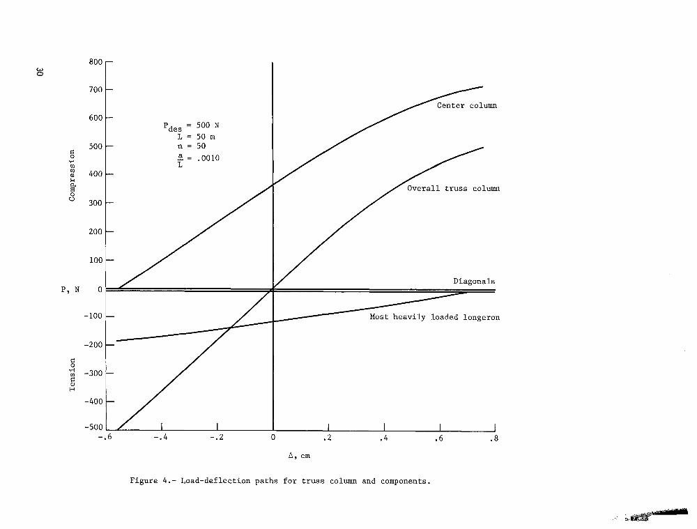
Insight into the load carrying mechanism of the truss-column can be
obtained by calculating the end deflections of the column under axial load.
The load-shortening curve for an imperfect column can be determined from
equation A-11. The corresponding loads in the center column, longerons, and
diagonals under the applied axial load P can be found from equations A-26,
A-28, A-14 and A-27, respectively. The load-deflection behavior for one
specific case, a 50 m column with a 500 N design load, is shown in figure 4.
The axial deflections of the overall column and members are plotted over the
complete range of loading from -Pdes (tension) to Pdes (compression).
Because of the spokes acting as a regulating mechanism maintaining constant
tension, the axial force in the diagonals, P,, is constant for all loadings.
At P = -Pdes the force in the center column drops to zero and all the loading
is being carried by the longerons. Similarly, when P = Pdes, the most heavily
loaded longeron becomes "slack" and will carry no additional load.
The nonlinear behavior of the truss-column due to the assumed imperfection
is evident when P approaches Pdes. However, the nonlinearity is fairly mild.
The reason for this is that the optimum column designed for an imperfection tends
9

to have a value of Pdes /P significantly less than 1.0. For this particular E
example Pdes/PE = .614. An efficient column design is achieved essentially
by making P des/PE small enough so that nonlinear bending effects are small.
NUMERICAL STUDIES
Using the design procedure developed in Appendix A, numerical results were
obtained for various values of the column length (5 m, 50 m, 500 m), design
load (5 N, 50 N, 500 N, 5000 N, 25000 N), assumed imperfection a/L (.OOOl-
.0060), and diagonal angle 8 (15"-75"). A value of 110.2 GN/m2 (16 x lo6 psi)
was used for the Young's modulus of the graphite/epoxy material in the center
column, longerons, spokes and diagonals. This is typical of a material
composed of mostly unidirectional, intermediate modulus fibers. The density
is taken to be 1522 kg/m3 (.055 lbm/in3).
The selection of minimum gage dimensions for the truss members is
somewhat arbitrary since it requires an assessment of the state of the art
in manufacture of graphite/epoxy materials which is also highly dependent on
both fiber and resin systems used. However, the following dimensions were
selected for the numerical studies:
O tubular wall thickness, tc, tS = .71 mm (.028 in)
o minimum tube radius for spokes and center column, rmin = 2.54 mn (.l in)
o minimum radius of solid cross section rsol min = .381 mm (.015 in) ,
It was also necessary to select values for the column imperfection
parameter a/L. In reference 8 where the parameter a/L as a measure of imper-
fections is discussed, the value a/L = .0025 is suggested for design calcu-
lations. However, this value was selected with reference to civil engineering
applications and it is expected here that careful fabrication procedures
which would be used for space applications would reduce the overall imper-
fections. Thus a value of a/L = .OOlO was used for most of the cases.
As mentioned in Appendix A, the effect of joint mass was also considered
by assuming the total mass of all joints to be a fixed percentage of the
structural mass. Accounting for joint mass in this way has no effect on the
10

other design parameters but it does provide a means for making rational com-
parisons between the truss-column and other columns without joints. In
equation A-38, the total mass of the truss-column M is defined to be a
product of a joint mass factor M, and the structural mass. A value of
MJ = 1.35 was selected for the nimerical stud
Deta ils of the designs for two values of
are shown in Table I. The constraint imposed
sions is seen by noting that the diagonal rad
by this value. The ratios of the design load
es.
diagonal angle (45"; 60")
by assuming minimum gage dimen-
us rd is usually designed
to the Euler buckling load,
Pdes/PE, for the more heavily loaded columns indicate the knockdown
in load carrying capability due to imperfections. For the very lightly
loaded columns, the longerons are often sized by the minimum gage value
r sol,min which causes Pdes/PE to be overly low.
The effect of the value of a/L on the truss-column mass for one
specific case is shown in figure 5. The mass penalty for a column designed
for an a/L = .OOlO compared with a/L = .OOOl is approximately 18%. The
number of bays in the optimum column is also shown for different designs.
As can be seen, larger assumed imperfections tend to reduce the number of
bays and thus increase the cross section and column bending stiffness.
Although a diagonal angle 0 of 45" was selected as a baseline angle,
it was recognized that this was not optimum for either structural efficiency
or manufacturability. The effect of diagonal angle 8 on the truss-column
mass is shown in figure 6. More structurally efficient columns have values
of e less than 45" and necessarily more bays. However, it is expected
that the cost of manufacturing is directly proportional to the number of bays
(and joints) and thus a higher value of 8 might be more desirable. Compari-
sons of the number of bays for designs with e = 60" versus 8 = 45" for
different column lengths and loads can be made from Table I.
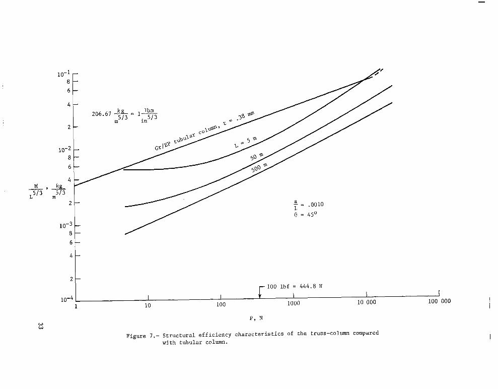
Finally, to compare the tension wire stiffened truss-column with other
column concepts, a structural efficiency plot for the truss-column and tubular
column is presented in figure 7. The structural efficiency parameter M/L5'3
was shown in reference 5 to be useful for comparing the masses of lightly
loaded columns at different values of the design load. A tubular column
11

design appears as a single, length independent line on a structural efficiency
plot using this -parameter. This allows for easy comparison between the
tubular column and other column concepts such as the wire stiffened truss-
column. The tubular column is of interest not only as a structural baseline
but also because its structural efficiency is very close to that of the double
tapered, nesting graphite/epoxy column described in references 2 and 4. The
graphite/epoxy tubular column plot in figure 7 represents an optimum design
which is critical in Euler buckling and has a wall thickness t = .015 and modulus
equal to that of the truss-column. For higher loadings, local wall buckling
would have to be considered; the point where this would be necessary and the
structural efficiency of columns in this range are indicated approximately by
the dashed line in figure 7.
Structural efficiency curves for truss-columns of three lengths (5 m,
50 m, 500 m) are also shown in figure 7. A diagonal angle e of 45" and an
assumed imperfection a/L of .OOlO were prescribed. The flattening out of the
curves for the 5 and 50 meter columns at low loadings is because the minimum
gage parameters are becoming active for these designs. Over most of the
load range, the 5 m truss-column is more efficient than the tubular column;
for the longer lengths (50 m, 500 m) this is even more significant. Struc-
tural efficiency plots of this type for other column concepts can be found
in reference 5 which can be used in comparisons with the tension stiffened
truss-column in this study.
CONCLUDING REMARKS
The structural efficiency of a wire-stiffened, expandable truss-column
is investigated by developing a design procedure for a minimum mass structure.
The design procedure employs a combined weight-strength and direct mass
minimization approach exploiting specific characteristics of the structure.
Numerical results are obtained for truss-columns with a wide variety of
lengths and design loads and the masses are compared with tubular column
designs. Specific conclusions obtained from this study are as follows:
12

(1) The wire-stiffened, expandable truss-column is si
structurally efficient than the baseline tu,bular
larly for longer lengths.
gnificantly more
column, particu-
(2) Design based on an assumed imperfection is import ant because
(a) it provides a criteria for determining the necessary value
for the diagonal number pretension, and (b) significant differences
in both the final configuration and mass of the structure compared
with the perfect case result.
(3) For short or lightly loaded columns the design may be dictated
by manufacturing minimum gage constraints and these must be included.
(4) For realistic automated design, the design/analysis procedure should
be sufficiently general to allow arbitrary bounds on design variables
and a general set of constraint functions. Nonlinear mathematical
programming methods allow the criteria to be met.
13

APPENDIX A
ANALYSIS OF THE TRUSS COLUMN
The analysis of the tension wire stiffened truss-column shown in
figures 1 and 2 is based on determining a set of equivalent beam exten-
sional, bending, and transverse shear stiffness for the truss. These equiva-
lent stiffnesses are used in the imperfect column analysis to predict the
overall behavior of the structure. The individual member loads in the
center column, longerons, diagonals, and spokes are then calculated from the
overall loads and deformations of the column. Knowing the member loads, the
failure of each component can be predicted. Finally, the optimum truss-
column is designed by minimizing the truss mass subject to constraints
on the different failure modes and side constraints on the design variables.
Equivalent Beam Stiffnesses for the Truss
The axial and bending stiffness for the truss-column are derived from
simple statics. Because the spokes are buckled in the unloaded column, the
diagonal members and the spokes do not contribute to the axial or bending
stiffnesses. The equivalent axial stiffness, C, can be written as
C = 3E,A, + EcAc (A-1 )
Noting that the center column lies at the centroid of the triangles which is
the neutral axis for the beam and neglecting the bending stiffnesses of the
individual members, the bending stiffness, D, can be written as
where R is shown in figure 2.
This can be rewritten in terms of the overall column length, L, the
number of bays in the column, n, and the diagonal angle, 8, as
2 D = E,A2L
2n2tan2e (A-3)
14

The transverse shear stiffness, Cs, is obtained from reference 10 as
c, = 3&.&j sine cos2e (A-4)
The transverse shear stiffness will be specified later so that the
transverse shear deflections in the column are negligible compared with
those due to bending. In the column analysis that follows, the effect of
transverse shear deformation is ignored.
Column Analysis with an Initial Imperfection
In reference 5, the effects of an initial imperfection in column straight-
ness were considered in the design of truss-columns. In the present study a
similar approach is used for the tension-wire stiffened column. The two pri-
mary implications of such an imperfection are that a bending moment and a
transverse shear force are induced in the column in addition to the axial
force. The momeht induced in an axially loaded column with a sinusoidal
imperfection in straightness is taken from reference 8 as
M=i++ sin F (A-5)
where P is the axial load, a is the maximum amplitude of the initial imper-
fection, x is an axial coordinate referenced from the end of the column, and
PE is the Euler buckling load of a perfect column which is defined as
2 pE = ti
L2
The maximum moment occurs at the center of the column (x = L/2) and is
obtained from equation A-5 as
M z1 Pa max - p/p,
(A-6)
(A-7)
The imperfection induced shear load V is determined by taking the derivative
of equation A-5 with respect to x. This results in
15

(A-8)
which has a maximum value at (x = 0) of
v
P T+
max = 1 - P/P E
(A-9)
For the imperfect column, the end shortening is a function of both the
strain along the column neutral axis and the transverse deflection, w. This
end shortening (A) under the axial load is a measure of the column's stiffness
which is of significance when considering a truss structure assembled from
these members. An expression for the end shortening, consistent with equation
A-5, can be derived by considering the nonlinear strain-displacement relation
for a column with a sinusoidal imperfection
where E = -p 2
C and since M = -D dw dx2 '
W= Pa
PE - P sin ?K L
L
Defining the end shortening A = u(o) - u(L) = - d" dx, 0 dx
equation A-10 can be rearranged and integrated to give
2L p/p, t1 - p/2pE) /+-+(a2T- L) 2
(1 - p/p,)2
(A-10)
(A-11)
Member Loads in the Truss
Now that the stress resultants have been determined from the beam-column
analysis, the loads in the longerons, the center column, the diagonals, and
spokes can be calculated. As mentioned previously, the diagonals and spokes
do not carry any of the bending or axial loading in the column; the forces
in these members are due only to the induced transverse shear and initial
16
---. -.. - _. ..-.. _.-... .._.. -_ .._....__ -...-- ._._ .._.... -_ -.-.._- -_-_. _ _. .._. _... _-._

forces. Because the center column lies along the beam's neutral axis it
carries none of the induced bending moment. Its load is due only to the
column axial force. The forces in the longerons are due to the column axial
force and the imperfection induced bending moment. The derivation of expres-
sions for these member forces is considered below.
Since the internal equilibrium of the truss-column is a statically
indeterminate problem, the member forces are determined by considering the
deformations and axial equilibrium at any point along the length. The
force in any longeron can be written in terms of the neutral axis strain,
e, and curvature, KS as
P, = A,E,E + A,E,RK + PIa (A-12)
where PIa is the as yet undetermined initial force in the longeron. The
force in the center column can be written similarly as
PC = AcEc~ + PIc (A-13)
where PIc is the initial force in the column. The diagonal members also
have an axial force component which must be considered for equilibrium. If
the diagonal members are assumed to be carrying a tensile force, T, the total
axial force component due to all six diagonals at any column cross section is
Fd = -6T sine (A-14)
Because the spokes are initially buckled, this axial component, Fd,
remains constant for all loadings.
For equilibrium of the unloaded column,
pd + 3P, + PC = 0
when E = K = 0.
Substituting equations A-12, A-13, and A-14 into A-15 gives
P 6T sine - PIc
Ia = 3 -
(A-15)
(~-16)

From the beam-column analysis the equilibrium equations can be written as
P E=- C (A-17)
M max K=- D (~-18)
where P is the total axial load on the column and Mmax is the moment due
to the imperfection and is defined in equation A-7. Substituting equations
A-16, A-17, A-18, and A-7 into equations A-12 and A-13 gives the force in the
most highly loaded longeron as
-pap,PE) + 2T sine - - 3
P IC
due to due to bending initial force
axial force moment
and the force in the column as
pc = P rl+1 + pIc
(A-19)
(A-20)
due to initial
axial force force
where n is a nondimensional stiffness parameter defined as
3A,EL n=r (A-21)
c c
The force in a single diagonal can be calculated by considering trans-
verse equilibrium of any beam cross section as
V Pd = max
4 case cos 30" - T
which after substitution of equation A-9 becomes
p cp.1 Pd = - -T
2fi case (1 - P/P,)
(A-22)
(A-23)
18

The force in the spokes can be calculated by considering equilibrium
between the two sets of diagonals and the spoke and is given by
pS = 2fi T cos (A-24)
The forces in all four components of the truss-column (longerons, center
co1 umn, diagonals, and spokes) have been related to the applied axial force, P,
and the initial member forces, P,_ and T. The values of these initial
ific design conditions for the lected by consideri;; spec forces are se
truss-column.
Design Conditions and Constraint Equations
To determine the initial,forces T and PIc and to design the minimum
mass truss-column for given values of P and column length, L, the following
design conditions are imposed:
(1) When the beam is loaded with an applied tensile force equal to
-Pdes' the force in the center column PC is zero. This
insures that any hinge joints along the center column will not
be put in tension.
(2) When the appl
column should
(3) When P = Pdes
ed compressive load P is equal to Pdes, the center
not buckle between the spoke supports.
the longerons must not be in compression.
(4) When P = Pdes, the induced transverse shear force at the beam ends
causes the force in one set of diagonals to drop to zero.
(5) At p = Pdes' 2% transverse shear deformation is allowed. The
diagonals are sized to provide the necessary shear stiffness for
this criteria to be met.
(6) The spokes are designed to buckle under the load induced by the
two sets of diagonal members connected at each spoke.
19

Design condition 1 is applied to equation A-20 to find the initial
COlUIIrI force, PIc, by Setting P = -Pdes
P des pIc = rl+l (A-25)
Equation A-20 now becomes
P pc=P+des
n+l n+l (~-26)
From condition 4 the initial tension T can be found by setting P = Pdes
and Pd = 0 in equation A-23. The result is
T= 'des (f)
20 case (1 - Pdes/PE) (A-27)
Substituting equations A-25 and A-27 into equation A-19 and replacing R =
L/(nfitane) yields the force in the longeron
' - 'des (f) tane
pL = 3(rl+l+ JJ- 2nP 'des
(1 - P/P,) -(l-Pdes/PE) (A-28)
Given the member forces, Pd, Ps, PC, PL, in terms of a design load,
'des' an applied load, P, and the geometric properties of components, the
minimum mass truss can be designed. The objective is to minimize the mass of
the structure subject to both equality and inequality constraints. A common
nomenclature for inequality constraints is used where
Gi(V) < 0; constraint satisfied
Gi(v) > 0; constraint violated
The equality and inequality constraints arise from the satisfaction of
the six design conditions. Since condition 1 has already been used to find
the initial column force, PIc, condition 2 is considered next.
20

The buckling load of the center column between spoke supports can be
written as
r2EcIcn 2
P = crit 'center column L2
(A-29)
where EC is the modulus and I, is the moment of inertia of the center
column.
Condition 2 can be expressed by setting P = Pdes in equation A-27 and
usinq equation A-29 as
2P des
G, = 1+ n
r2E I c c n2/L2 - '*' (A-30)
In calculating G,, the center column moment of inertia Ic is calculated
for either an expression for a hollow thin walled tube or a solid circular
member depending on the particular design conditions.
Condition 3 can be written similarly by setting P = Pdes in equation
A-28 as
G2 =
Pdesh) 30 -
pdes (F) tane (n+2n)
- p/p,)
1.0 (A-31)
Condition 4 was satisfied by selection of the initial tension force, T,
in the diagonal members. These diagonal members still remain to be sized,
however, which will be done by considering condition 5.
To insure that transverse shear deformation has a small effect on the
buckling of the truss-column, the diagonal member area is selected so that.
the classical Euler buckling load is reduced only by 2%. From reference 8,
the buckling load for a shear flexible column is
P =A- cr pE 1+ c
S
(A-32)
21
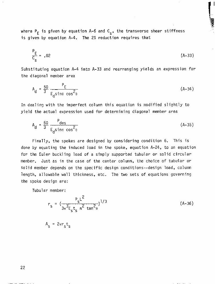
where PE is given by equation A-6 and Cs, the transverse shear stiffness
is given by equation A-4. The 2% reduction requires that
pE
%= l O2 (A-33)
Substituting equation A-4 into A-33 and rearranging yields an expression for
the diagonal member area
A ~50 pE d 3 Edsine cos2e
(A-34)
In dealing with the imperfect column this equation is modified slightly to
yield the actual expression used for determining diagonal member area
Ad = y ‘des
Edsine cos2e (A-35)
Finally, the spokes are designed by considering condition 6. This is
done by equating the induced load in the spoke, equation A-24, to an equation
for the Euler buckling load of a simply supported tubular or solid circular
member. Just as in the case of the center column, the choice of tubular or
solid member depends on the specific design conditions--design load, column
length, allowable wall thickness, etc. The two sets of equations governing
the spoke design are:
Tubular member:
s (
PsL2 r = >
l/3
3T3ESts n2 tan28 (~-36)
AS = 2rrsts
22

Solid member:
r = s (
4 PsL2
TITLE, n2 tan28 )1/4 (A-37)
By applying conditions l-6, either direct expressions or constraint
equations have been written governing design of components of the truss
column. It should be noted that by the use of equations A-35 and A-36 or
A-37 the diagonals and spokes can be sized directly. However, two design
variables, the longeron radius rR and the center column radius rc, remain
undetermined and must be selected to give an overall minimum mass. The over-
all design problem, then, is a combination of both weight-strength design
methods and direct minimization of the structure mass. The undetermined
variables rc and rR are determined by minimizing the truss mass which
can be written
M = MJL(&& + pCAC + 6PdAd/sine + fi PsAs/tane) (A-38)
where Ad and A, are found from equations A-35 and A-36 or A-37. The
factor MJ is used to account for the mass of the joints in the truss
and can be selected arbitrarily since it has no effect on the design and
is used only to produce a realistic total mass for the truss.
Equation A-38 can be minimized to determine rc and rR subject to
constraints G, and G2 (equations A-30 and A-31) and lower bounds on
rc and rR using nonlinear mathematical programming techniques. In this
study an available computer code, CONMIN (ref. 9), based on a feasible
direction method was used to perform the numerical studies.
23

REFERENCES
1. Mikulas, M. M., Jr.; Bush, H. G.; and Card, M. F.: Structural
Stiffness, Strength and Dynamic Characteristics of Large Tetra-
hedral Space Truss Structures. NASA TM X-74001, March 1977.
2. Bush, H. G.; Mikulas, M. M., Jr.; and Heard, Walter L., Jr.:
Some Design Considerations for Large Space Structures. AIAA J.
Vol. 16, No. 4, April 1978, pp. 352-359.
3. Nansen, R.H.; and DiRamio, H.: Structures for Solar Power
Satellites. Astronautics and Aeronautics, October 1978.
4. Bush, H. G.; and Mikulas, M. M., Jr.: A Nestable Tapered
Column Concept for Large Space Structures. NASA TM X-73927,
July 1976.
5. Mikulas, M. M., Jr.: Structural Efficiency of Long Lightly
Loaded Truss and Isogrid Columns for Space Applications.
NASA TM-78687, July 1978.
6. Powell, D. J.; and Browning, L.: Automated Fabrication of
Large Space Structures. Astronautics and Aeronautics, Octo-
ber 1978.
7. Hedgepeth, J. M.; Mikulas, M. M., Jr.; and MacNeal, R. H.:
Practical Design of Low-Cost Large Space Structures. Astro-
nautics and Aeronautics, October 1978.
a. Timoshenko, S. P.; and Gere, J. M.: Theory of Elastic Stability.
Second Edition, McGraw Hill Book Company, 1961.
24

REFERENCES
(continued)
9. Vanderplaats, Garret N.: CONMIN - A Fortran Program for Con-
strained Function Minimization User's Manual. NASA TM X-62282,
August 1973.
10. Greene, W. H.: Continuum Models for Static and Dynamic Analysis
of Repetitive Trusses. Masters Thesis, George Washington Uni-
versity, October 1977.
25

TABLE I. - DETAILS OF MINIMUM MASS GRAPHITE, TENSION-WIRE
STIFFENED TRUSS-COLUMNS
'des M n
(N) (kg)
L = 5m
{
L = 50m
a/L = .OOlO e = 45"
.381
.381
.549
1.13
2.66 --.__
5. 1.17 89 .324 .381 .254 .160
50. 1.96 72 .401 .497 .205 .614
.394 .589
5000. 1 16.8 1 31 1 ,931 1 1.97 19.6 1 .825 1 2.74 .417 .726
25000. 42.3 22 1.31 3.01 41.8 1.85 6.32 .459 .780
L = 500m
L
~. 3.41
8.92
24.0
68.5
.134
.199
.260
.334
.414
L = 5m a/L = .OOlO e = 60"
.738 1 .029 .070
.099
.208
.809
2.53
5.
50.
500.
5000.
25000.
22
32
19
12
7
.768
1.22
2.79
7.96
20.4
.294 .617
.314 .763
.419 .801
.244 .915 -- I .-. -_
L = 50m
L = 500m
5. 28.5 92 50. 74.0 68
500. 204. 47 5000. 620. 31
25000. 1415. 22
_. .381
.473
1.10
2.76
5.90 --
- .206
.227 L .297
.314
.410
1.46
3.36
9.39
27.9
57.1
.496 4.79 .381
.987 12.4 .381
1.90 33.6 .381
3.63 93.9 1.05
5.37 201. 2.36
- 26
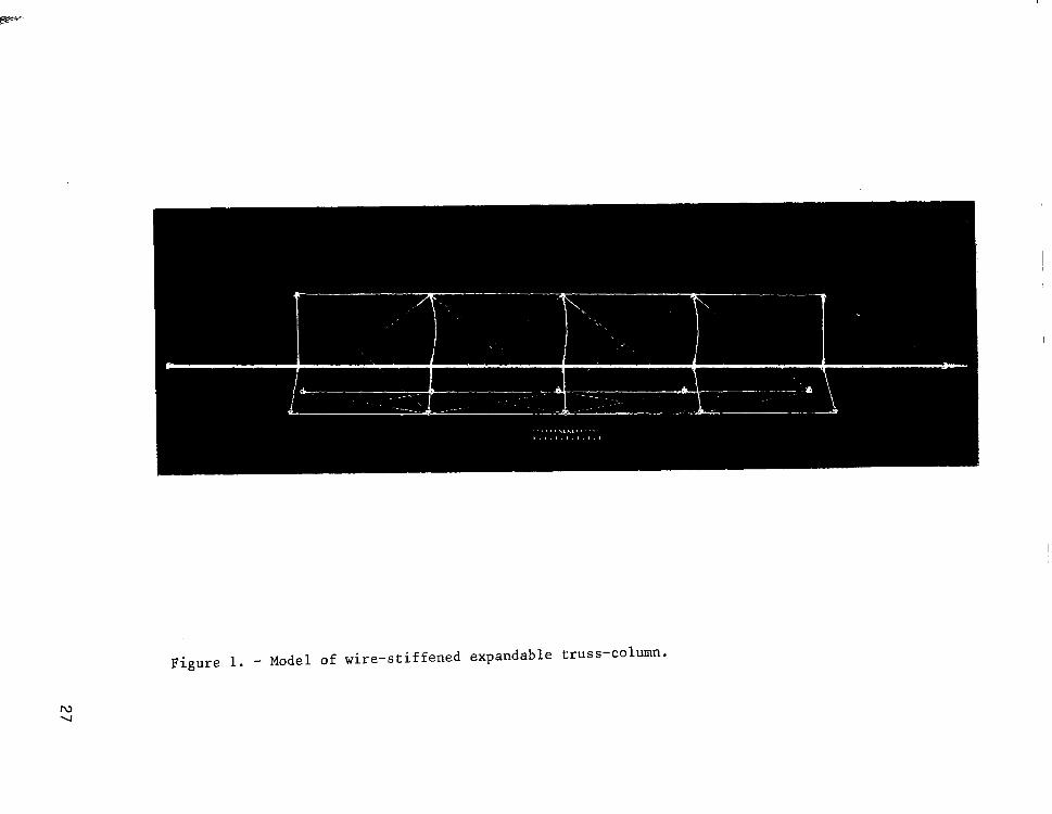
Figure 1. - Model of wire-stiffened expandable truss-column.

L Center column
Figure 2.- Geometry of the t ension-wire stiffened ~01~ .

1.8
1.6
1.4
1.2
M 1.0 Mmin
.8
.6
L=50nl P = 500N
a/L = .OOl 9 = 450
Diagonals I
70
n, number of bays
column
/ Longerons
Figure 3.- Optimum mass distributions for the truss-column components.
29
w 0
800
700
60C
i
500
4OG
300
200
1oc
a
-100
-200
g -Ii z
-300
:
-400
'des = 500 N L=50m n = 50 a = .OOlO L
Most heavily loaded longeron
I I 1
.2 .4 .6 .8
A, cm
Figure 4.- Load-deflection paths for truss column and components.

M
kg
L= 50 m P = 500 N 8 = 450
I I .OOlO
a/L
.OlOO
Figure 5.- Change in mass of the truss column as a function of initial imperfection.

1.8 r
P = 500 m L= 50 m a - = .OOlO L
.9 I I I I I I 15O 25' 35O 45O 55O 65' 75O
Figure 6.- Effect of diagonal angle on column mass.
-
10-l 8 6
- - 1 10-2
8
6
4 --.-9-k M ,5/3 513 m
10-3 8
6
4
2 l_
rlOO lbf = 444.8 N
10-4 I I + I I I 1 10 100 1000 10 000 100 000
p, N w w
Figure 7.- Structural efficiency characteristics of the truss-column compared with tubular column.
a - = .OOlO L 0 = 45O
I--

1. Report No.
NASA CR-3273 2. Government Accession No.
4. Title and Subtitle
A DESIGN. PROCEDURE FOR A TENSION-WIRE
STIFFENED TRUSS-COLUMN
7. Author(s)
WILLIAM H. GREENE
9. Performing Organization Name and Address
Jentron.~International, Inc. Hampton Technical Center 3221 N. Armistead Avenue HamDton. VA 73666
2. Sponsoring Agency Name and Address
National Aeronautics and Space Administration Washington, DC 20546
13. Type of Report and Period Covered
5. Supplementary Notes
Langley Technical Monitor: Martin M. Mikulas, Jr. Topical Report
6. Abstract
A deployable, tension-wire stiffened truss-column configuration is considered for space structure applications. An analytical procedure is developed for design of the truss-column and exercised in numerical studies. The analytical procedure is based on using equivalent beam stiffness coefficients in the clas- sical analysis for an initially imperfect beam-column. Failure constraints are then formulated which are used in a combined weight/strength and nonlinear math- ematical programning automated design procedure to determine the minimum mass column for a particular combination of design load and length. Numerical studies show the mass characteristics of the truss-column for broad ranges of load and length. Comparisons of the truss-column with a baseline tubular column are made using a special structural efficiency parameter for this class of columns.
7. Key Words (Suggested by Author(s)1
large space structures, columns, automated design, tension-stiffened, prestress, truss-columns, triangular columns
-.- --___ 18. Distribution Statement
Unlimited - Unclassified
Subject Category 39
9. Security Classif. (of this report1
Unclassified
I 20. Security Classif. (of this pagel
Unclassified I
21. No. of Pages 22. Price‘
33 $4.50
‘For sale by the National Technical Information Service, Springfield, Virginia 22161 NASA-Langley, 1980