Hypersonic Boundary/Shear Layer Transition for Blunt to ... · and embodies several physical gas...
35
RTO-MP-AVT-111 22 - 1 UNCLASSIFIED/UNLIMITED UNCLASSIFIED/UNLIMITED Hypersonic Boundary/Shear Layer Transition for Blunt to Slender Configurations – A NASA Langley Experimental Perspective Thomas J. Horvath, Scott A. Berry, and N. Ronald Merski NASA Langley Research Center MS 408A Hampton, VA 23681 USA [email protected] ABSTRACT Heating augmentations and temperature increases resulting from boundary layer/shear layer transition during hypersonic flight through the atmosphere of Earth or other planets impose critical constraints on the design of vehicle thermal protection systems and are well documented in the literature. Laminar-to-turbulent transition effects on local surface heat transfer determine thermal protection system material selection, placement, and thickness. In terms of vehicle performance, transition can influence vehicle aerodynamics and scramjet propulsion system performance. The development of numerical tools for the reliable and rapid prediction of boundary layer transition on complex vehicle shapes, however, continues to be hindered by the lack of a practical capability to model the complex physics associated with the transition process. Therefore, until a credible approach to transition prediction is identified that can be implemented in a rapid assessment framework, vehicle designers will continue to rely heavily on empirically derived transition prediction strategies derived from ground-based measurements. With an emphasis on hypersonic boundary layer transition, the focus of the present paper is to highlight recent aerothermodynamic studies in NASA Langley Research Center’s conventional hypersonic wind tunnels (as opposed to high enthalpy, impulse facilities) in support of agency access-to-space and planetary entry programs. Configurations of interest include the Shuttle Orbiter and proposed advanced space transportation concepts (reusable and partially reusable crew launch/return vehicles, single and multiple stage-to-orbit rocket /airbreathing propulsion system concepts, hypersonic cruise vehicles, and planetary aerocapture /entry vehicles). Characterization of surface heating on complex shapes and deflected control surfaces and fluid dynamic phenomenon, such as flow separation and wake closure, are addressed. 1.0 AEROTHERMODYNAMICS 1.1 Definition In a classic sense, the flow regime referred to as hypersonics is generally considered to begin around Mach 5 and embodies several physical gas dynamics and high temperature flow phenomena that become progressively more important as the Mach number increases. Hypersonic aerothermodynamics has been characterized herein as a blend of several disciplines that are relevant to the vehicle designer: (1) aerodynamic forces, moments, and surface pressure distributions and loads; (2) aeroheating, both convective and radiative; and (3) fluid dynamics, which may include flow separation and reattachment, shock interactions, and high Paper presented at the RTO AVT Specialists’ Meeting on “Enhancement of NATO Military Flight Vehicle Performance by Management of Interacting Boundary Layer Transition and Separation”, held in Prague, Czech Republic, 4-7 October 2004, and published in RTO-MP-AVT-111.
Transcript of Hypersonic Boundary/Shear Layer Transition for Blunt to ... · and embodies several physical gas...
RTO-MP-AVT-111 22 - 1
UNCLASSIFIED/UNLIMITED
UNCLASSIFIED/UNLIMITED
Hypersonic Boundary/Shear Layer Transition for Blunt to Slender Configurations – A NASA Langley Experimental Perspective
Thomas J. Horvath, Scott A. Berry, and N. Ronald Merski NASA Langley Research Center
MS 408A Hampton, VA 23681
USA
ABSTRACT
Heating augmentations and temperature increases resulting from boundary layer/shear layer transition during hypersonic flight through the atmosphere of Earth or other planets impose critical constraints on the design of vehicle thermal protection systems and are well documented in the literature. Laminar-to-turbulent transition effects on local surface heat transfer determine thermal protection system material selection, placement, and thickness. In terms of vehicle performance, transition can influence vehicle aerodynamics and scramjet propulsion system performance. The development of numerical tools for the reliable and rapid prediction of boundary layer transition on complex vehicle shapes, however, continues to be hindered by the lack of a practical capability to model the complex physics associated with the transition process. Therefore, until a credible approach to transition prediction is identified that can be implemented in a rapid assessment framework, vehicle designers will continue to rely heavily on empirically derived transition prediction strategies derived from ground-based measurements. With an emphasis on hypersonic boundary layer transition, the focus of the present paper is to highlight recent aerothermodynamic studies in NASA Langley Research Center’s conventional hypersonic wind tunnels (as opposed to high enthalpy, impulse facilities) in support of agency access-to-space and planetary entry programs. Configurations of interest include the Shuttle Orbiter and proposed advanced space transportation concepts (reusable and partially reusable crew launch/return vehicles, single and multiple stage-to-orbit rocket /airbreathing propulsion system concepts, hypersonic cruise vehicles, and planetary aerocapture /entry vehicles). Characterization of surface heating on complex shapes and deflected control surfaces and fluid dynamic phenomenon, such as flow separation and wake closure, are addressed.
1.0 AEROTHERMODYNAMICS
1.1 Definition In a classic sense, the flow regime referred to as hypersonics is generally considered to begin around Mach 5 and embodies several physical gas dynamics and high temperature flow phenomena that become progressively more important as the Mach number increases. Hypersonic aerothermodynamics has been characterized herein as a blend of several disciplines that are relevant to the vehicle designer: (1) aerodynamic forces, moments, and surface pressure distributions and loads; (2) aeroheating, both convective and radiative; and (3) fluid dynamics, which may include flow separation and reattachment, shock interactions, and high
Paper presented at the RTO AVT Specialists’ Meeting on “Enhancement of NATO Military Flight Vehicle Performance byManagement of Interacting Boundary Layer Transition and Separation”, held in Prague,
Czech Republic, 4-7 October 2004, and published in RTO-MP-AVT-111.
Report Documentation Page Form ApprovedOMB No. 0704-0188
Public reporting burden for the collection of information is estimated to average 1 hour per response, including the time for reviewing instructions, searching existing data sources, gathering andmaintaining the data needed, and completing and reviewing the collection of information. Send comments regarding this burden estimate or any other aspect of this collection of information,including suggestions for reducing this burden, to Washington Headquarters Services, Directorate for Information Operations and Reports, 1215 Jefferson Davis Highway, Suite 1204, ArlingtonVA 22202-4302. Respondents should be aware that notwithstanding any other provision of law, no person shall be subject to a penalty for failing to comply with a collection of information if itdoes not display a currently valid OMB control number.
1. REPORT DATE 01 OCT 2004
2. REPORT TYPE N/A
3. DATES COVERED -
4. TITLE AND SUBTITLE Hypersonic Boundary/Shear Layer Transition for Blunt to SlenderConfigurations A NASA Langley Experimental Perspective
5a. CONTRACT NUMBER
5b. GRANT NUMBER
5c. PROGRAM ELEMENT NUMBER
6. AUTHOR(S) 5d. PROJECT NUMBER
5e. TASK NUMBER
5f. WORK UNIT NUMBER
7. PERFORMING ORGANIZATION NAME(S) AND ADDRESS(ES) NASA Langley Research Center MS 408A Hampton, VA 23681 USA
8. PERFORMING ORGANIZATIONREPORT NUMBER
9. SPONSORING/MONITORING AGENCY NAME(S) AND ADDRESS(ES) 10. SPONSOR/MONITOR’S ACRONYM(S)
11. SPONSOR/MONITOR’S REPORT NUMBER(S)
12. DISTRIBUTION/AVAILABILITY STATEMENT Approved for public release, distribution unlimited
13. SUPPLEMENTARY NOTES See also ADM201868, RTO-MP-AVT-111 Enhancement of NATO Military Flight Vehicle Performance byManagement of Interacting Boundary Layer Tranisition and Separation (L’amelioration des performancesdes vehicules aeriens militaires de l’OTAN par la gestion de l’interaction entre la transition et ledecollement de la couche limite)., The original document contains color images.
14. ABSTRACT
15. SUBJECT TERMS
16. SECURITY CLASSIFICATION OF: 17. LIMITATION OF ABSTRACT
UU
18. NUMBEROF PAGES
34
19a. NAME OFRESPONSIBLE PERSON
a. REPORT unclassified
b. ABSTRACT unclassified
c. THIS PAGE unclassified
Standard Form 298 (Rev. 8-98) Prescribed by ANSI Std Z39-18

Hypersonic Boundary/Shear Layer Transition for Blunt to Slender Configurations – A NASA Langley Experimental Perspective
22 - 2 RTO-MP-AVT-111
UNCLASSIFIED/UNLIMITED
UNCLASSIFIED/UNLIMITED
temperature gas dynamics [1]. For some, aerothermodynamics encompasses the design, development, and flight of a full spectrum of aerospace vehicles across the speed regime (subsonic/continuum-to-hypersonic/low density). The focus of the present paper is to highlight continuum hypersonic design issues identified with or resolved from wind tunnel measurements on vehicles experiencing transition of attached or separated flow from a laminar to a turbulent state. Turbulent-to-laminar transition that is possible with low altitude maneuvering vehicles, is recognized, but not addressed in the context of this overview.
1.2 Hypersonic Vehicle Classification Characteristics of the hypersonic flight environment depend to a large extent on vehicle shape and scale, both of which are directly influenced by mission requirements. The complexity of a vehicle shape is often (but not always) proportional to mission requirements. For either Earth entry/cruise or planetary robotic missions, a “complex” vehicle shape refers to the presence of many, if not all, of these components: heat shields with afterbody (axisymmetric or nonaxisymmetric forebody), fuselage, canopy, wings, strakes, and control surfaces (e.g., body flap(s), vertical tail(s), dorsals, canards, etc.). For purposes of discussion in this paper, post shock Mach number, which is largely determined by vehicle shape and/or angle of attack, is used to identify three classes of hypersonic vehicles: (1) Blunt configurations (e.g., Viking, or Apollo type capsules), these vehicles with large radius of curvature typically fly with a low entry angle of attack to provide high drag characteristics and produce a strong detached bow shock. Forebody post shock Mach numbers are principally subsonic (M<1) only becoming supersonic as the flow rapidly expands and accelerates around the forebody corner; (2) Moderately blunt configurations (e.g., winged or lifting type configurations such as the US shuttle), these vehicles maneuver at relatively high angles of attack to manage heating rates and loads during entry. At high hypersonic conditions, post shock Mach numbers are usually supersonic (1<M<4); and (3) Slender configurations (e.g., missiles, waveriders, or scramjet cruise vehicles), these vehicles generally operate at relatively low altitudes and angles-of-attack and, in the case of scramjet powered concepts, to maximize propulsion system performance. As a result of low shock inclination angles, post shock Mach numbers along the integrated forebody/propulsion system flow path are usually hypersonic (M>5).
1.3 Experimental Methods The experimental perspectives presented herein are limited to the testing experiences of the present authors at the NASA Langley Research Center (LaRC) and are not intended to be all inclusive of aerothermodynamic design issues related to hypersonic boundary layer or shear layer transition. The data presented have been based on measurements obtained in the NASA LaRC Aerothermodynamics Laboratory (LAL). This laboratory presently consists of three hypersonic wind tunnels that represent 100% of NASA’s (and 50% of the nation’s) conventional aerothermodynamic test capability (as opposed to high enthalpy, impulse facilities such as shock or expansion tunnels) [2]. Collectively, they provide a wide range of Mach number simulation (6-18), unit Reynolds number (0.01-8 million/ft), and normal shock density ratio (6 and 12). This range of hypersonic simulation parameters is due, in part, to the use of two different test gases (air and tetraflouromethane-3 times the molecular weight of air), thereby making the facilities unique national assets. The LAL facilities offer run times from 20 sec to 20 minutes (as opposed to milli or micro sec in impulse tunnels) and are ideally suited for fast-paced aerodynamic performance and aeroheating, and for transition studies aimed at screening, assessing, optimizing, and bench-marking (when combined with computational fluid dynamics) advanced aerospace vehicle concepts. Because of well-characterized flow in terms of composition and uniformity, the LAL facilities are also appropriate for basic fundamental flow physics research.
Experimental measurement techniques typically used during aerothermodynamic testing include (but are not limited to) thermographic phosphors and thin-film thermometry, which provide global and discrete surface

Hypersonic Boundary/Shear Layer Transition for Blunt to Slender Configurations – A NASA Langley Experimental Perspective
RTO-MP-AVT-111 22 - 3
UNCLASSIFIED/UNLIMITED
UNCLASSIFIED/UNLIMITED
heating respectively; oil-flow, which provides surface streamline information; schlieren, which provides shock details; hot wire anemometry, which provides wind tunnel free-stream noise spectra and shear layer rms spectra, and six component strain gage balances to provide aerodynamic force and moment loads [1,2]. Most of the surface heating data that is obtained in the LAL is from phosphor thermography [3,4]. The primary advantage of the phosphor technique is the global resolution of quantitative heat transfer data. Such data can be used to identify the heating footprint of complex, three-dimensional flow phenomena (e.g., separation/reattachment, transition fronts, turbulent wedges, boundary layer vortices, etc.) that are extremely difficult to resolve by discrete measurement techniques.
2.0 HYPERSONIC VEHICLE DESIGN
2.1 Motivation Whether supporting the development of advanced space transportation concepts, hypersonic cruise vehicles, or planetary spacecraft, the aerothermodynamic design process starts at the system analysis level whereby trade and packaging studies directed at achieving mission requirements dictate the initial shape (outer mold line) of the proposed vehicle. Optimally, an iterative experimental and computational screening process is first used to identify low-speed entry or landing characteristics and high-speed lift-to-drag (L/D) and aerodynamic trim requirements. Successful aerothermodynamic closure from the perspective of aerospace vehicle design is achieved by balancing aerodynamic performance against management of heat rates and loads. Heat rates and loads from boundary layer transition during hypersonic ascent, cruise, or entry can represent an important thermal protection system (TPS) design constraint [5]; thus, the accurate prediction of transition onset and associated heating augmentation levels is generally of vital importance to the successful design and flight of agency advanced transportation system concepts. Regardless of diverse mission requirements (e.g., reusable and partially reusable crew launch/return vehicles, single and multiple stag-to-orbit rocket/airbreathing propulsion system concepts, hypersonic cruise vehicles/missiles, or planetary aerocapture/entry vehicles) accurate transition prediction and/or control is essential from the perspective of economics (e.g., vehicle weight reduction, simplified mission operations/maintenance), risk reduction/crew safety (e.g., TPS performance under abort conditions or TPS tolerances to damage and repair), and enhanced mission flexibility (e.g., propulsion system robustness, improved aerodynamic control and cross range capability). System trade studies often justify these and other potential benefits derived from an enhanced understanding of hypersonic transition. Regarding transition prediction on complex vehicle concepts, a “bridge” between basic fundamental research and application to design does exist, but in the opinion of the authors, the span is sizable and the road between is at times not easily driven. On the experimental side, the general recognition of the influence of facility wall radiated noise upon hypersonic transition measurements combined with the lack of an operational hypersonic low disturbance wind tunnel, has had an adverse effect on the pace of hypersonic transition research. Complementary numerical work regarding stability theory and simulation of hypersonic transition has progressed for simple analytic shapes. Without a comprehensive understanding of the transition mechanisms involved on complex, highly three-dimensional geometries, the routine application of these predictive techniques to support NASA’s programs remains a challenge and generally does not meet the needs of the designer for timely, optimal, and cost-effective aerothermodynamic vehicle design and screening. Regardless of the source of aerothermodynamic information (experimental or theoretical), the “applied” engineering community must accommodate conservative thermal protection system (TPS) margins due to rather large uncertainties in our ability to predict transition along a vehicle surface during an assumed flight path.

Hypersonic Boundary/Shear Layer Transition for Blunt to Slender Configurations – A NASA Langley Experimental Perspective
22 - 4 RTO-MP-AVT-111
UNCLASSIFIED/UNLIMITED
UNCLASSIFIED/UNLIMITED
2.2 Limitations of the Conventional Wind Tunnel and Numerical Simulation The transition process is complex and determining how and when it occurs in flight depends on numerous parameters (e.g., Mach number, unit Reynolds number, wall temperature, 3-D effects, bluntness, mass injection, gas chemistry, and surface roughness). It has been stated [6] in the transition community that “…one should not expect a transition Reynolds number obtained in any wind tunnel, conventional or quiet, to be directly relatable to flight…one can duplicate [flight values of] free stream Mach number and Reynolds number but generally not velocity or temperature profiles within the boundary layer…” Ballistic ranges have been used with success to address some issues related to wall radiated noise from conventional tunnels but have their own challenges as well. Experimental high-enthalpy facilities that permit assessment of flow chemistry effects on flow transition exist but the debate on the low disturbance characteristics of these facilities persist. Linear stability theory or simulation of hypersonic transition using direct numerical simulation (DNS) continues to advance [7,8], for simple analytic shapes and flow phenomenon, but without details of the free-stream disturbance environment and significant computational resources, the application of these predictive techniques to support the rapid and iterative aerothermodynamic design/screening process is not presently possible.
2.3 Practical Application of Transition Research in Conventional Hypersonic Facilities In the mid 1970s numerical simulation capabilities were not of sufficient maturity to appreciably impact the aerothermodynamic design process. Historically, hypersonic ground-based facilities provided a vast majority of aerothermodynamic information in the hypersonic continuum regime and were largely responsible for the initial success of crewed entry vehicles such as Mercury, Gemini, and Apollo, and later the Shuttle Orbiter. In the two decades since the Shuttle became operational, the aerothermodynamic vehicle design process has slowly shifted away from the exclusive domain of ground-based facilities. Advancements in CFD capabilities within the last decade or so have placed the numerical simulation community in a position to contribute significantly to the design of aerospace concepts possessing complex geometries (see section 1.2 for definition of complex shape). CFD that has been validated with ground-based measurement is now routinely used to predict surface and flow-field environments for full-scale vehicles at atmospheric conditions representative of flight (e.g., pressure, temperature, density, velocity, and gas composition). The advantages of CFD in predicting aerothermodynamic environments associated with attached laminar flows at hypervelocity flight conditions (where high temperature gas effects may persist) are well documented, and numerical simulation is generally recognized as the primary source for aerothermodynamic information. However, the confidence level of CFD to accurately and/or rapidly model complex flow phenomenon at hypersonic speeds such as flow separation/reattachment and flow transition is considered to be much lower, and as a consequence, the synergistic coupling of CFD with experiment is still essential.
Regarding transition, the vehicle designer has no reliable, practical, and timely method of predicting when and how transition will occur in hypersonic cruise or in flight during planetary (or Earth) entry; and if it occurs, to quantify its impact on the local environments particularly those associated with flow separation and/or reattachment. The designer is thus asked to make educated considerations: to identify likely transition instability mechanisms (e.g., 1st and 2nd modes, cross flow, Goertler) on the full-scale vehicle at flight conditions as well as those present on a scaled model in a wind tunnel (they may not be the same); to understand how these instabilities may couple to each other (mode interactions) and to the wind tunnel disturbances; and finally, to identify parametric trends (e.g., nose bluntness, angle-of-attack) that may or may not be influenced by tunnel noise. It is generally accepted that boundary layer transition can result from instabilities, mode interactions, or from transition bypass mechanisms (a term commonly used to identify transition modes which bypass the linear growth process of disturbances). When vehicle surface roughness is present (a typical bypass), it is believed that the free stream noise contamination present in conventional

Hypersonic Boundary/Shear Layer Transition for Blunt to Slender Configurations – A NASA Langley Experimental Perspective
RTO-MP-AVT-111 22 - 5
UNCLASSIFIED/UNLIMITED
UNCLASSIFIED/UNLIMITED
tunnels has only a marginal, but still conservative effect, on the location of transition. Specifically, experimental studies [9] have suggested that in general, facility noise has little effect for roughness heights large enough to be considered “effective” (turbulence initiated immediately downstream of the roughness element site). It is recognized there may be an influence of wind tunnel noise on transition onset data derived from roughness that are less than “effective” (transition not at, but down stream of roughness site) [10,11]. A recent review of hypersonic roughness-dominated transition suggests the TPS for reentry vehicles in the near future will continue to be roughness dominated [12]. Thus, a large part of the rationale for the continued use of the conventional hypersonic wind tunnel in characterizing boundary layer transition aerothermodynamics lies in the fact that despite improvements in the manufacture and control of TPS, isolated or distributed surface roughness (e.g., steps, gaps, interfaces) will exist.
The ability to rapidly determine the heating environments on complex vehicle shapes including quantifying the effects of TPS surface roughness in terms of empirical correlations is presently derived from conventional ground-based testing. Unfortunately, budgetary pressures presently threaten the future of NASA LAL hypersonic wind tunnels and thus, the ability to rapidly assess/screen/optimize complex vehicle concepts. Looking back, all of NASA’s recently proposed hypersonic X-vehicles and a number of planetary entry or sample return spacecraft have been tested in the LaRC LAL. The majority of these aerothermodynamic studies emphasized hypersonic transition and the characterization of surface roughness [13-28], including surface roughness effects on the Shuttle Orbiter. Traditional ceramic TPS tiles such as those used on the Shuttle Orbiter are susceptible to launch and landing-induced damage and have been known to develop isolated surface protrusions (tile gap fillers). Both forms of localized surface perturbations (cavities and/or protuberances) have been responsible for the occurrence of early (Mach number > 10) boundary layer transition in flight [29, 30], and characterization of transition due to TPS damage and/or repair is currently a major part of the Shuttle Return-to-Flight (RTF) program. Stitching patterns on the Shuttle leeside thermal blankets (and similar ceramic-based blankets under consideration for windward application) yield another form of local roughness. Strategies for achieving an economically viable next generation space transportation system with an emphasis on risk reduction and enhanced crew safety will include the continued refinement of these existing TPS as well as alternative TPS such as metallic systems and/or ablators. While it is recognized that improvements in TPS materials manufacturing technology have been made since the first flight of the Shuttle, most new materials have not been flight demonstrated. Metallic TPS panels that were proposed for use on the sub orbital RLV demonstrator X-33 [31] were have been susceptible to thermally induced expansion/bowing producing a distributed roughness in the form of a wavy wall [32]. Until a truly “smooth” TPS system exists and/or a credible and rapidly applied mechanism based [33] approach to transition prediction is developed, the TPS designer will continue to rely on prediction strategies that include empirical methods derived from ground-based measurements.
Low disturbance wind tunnel technologies developed and incorporated into supersonic and hypersonic wind tunnels at the NASA LaRC in the 1980s and 1990s have established the influences of noise on transition and have advanced the understanding of transition via stability experiments conducted in these low disturbance facilities [34-55] as well as in conventional tunnels {56-60]. Yet, despite advances in low disturbance wind tunnel technology, relatively few low disturbance supersonic or hypersonic facilities exist. NASA LaRC deactivated the only successfully demonstrated hypersonic low disturbance wind tunnel in the early 1990s and did not pursue construction of a Mach 8 facility due to technical problems and associated cost overruns. Supersonic low disturbance facilities operational today are typically deficient in Reynolds number relative to representative flight conditions. A Mach 6 low disturbance tunnel is under development [61] but unfortunately has not been able to achieve “quiet” conditions at design Reynolds numbers. If successfully demonstrated to run “quiet” at higher Reynolds numbers, the tunnel would be very useful for hypersonic instability research and to develop mechanism-based prediction methods; however, the low operating temperature of this Ludweig tube is generally not conducive for benchmark surface heat transfer

Hypersonic Boundary/Shear Layer Transition for Blunt to Slender Configurations – A NASA Langley Experimental Perspective
22 - 6 RTO-MP-AVT-111
UNCLASSIFIED/UNLIMITED
UNCLASSIFIED/UNLIMITED
measurements associated with aeroheating/assessment/screening on complex shapes. Thus, despite recognized limitations, conventional hypersonic facilities continue to serve as the primary source for experimental data [13-28] from which to develop empirical methods for flight transition prediction.
3.0 IMPACTS OF FLOW TRANSITION ON VEHICLE DESIGN VIA TESTING IN NASA LANGLEY CONVENTIONAL HYPERSONIC WIND TUNNELS
As an overview paper of NASA LaRC contributions to aerothermodynamics relating to hypersonic transition, this section will highlight some of the relevant impacts made by the authors to hypersonic vehicle design across a broad spectrum of configuration shapes. Details of how the results were integrated into the respective programs can be found in the references cited with each subsection. The synopsis of aerothermodynamic contributions is presented utilizing both global and discrete heating measurements. Flow visualization in the form of surface oil flows is presented when necessary to provide additional insight.
3.1 Blunt Configurations A review of high drag, blunt body gas dynamics associated with a spacecraft as it enters the atmosphere of Earth (e.g., sample return mission) or other planets (e.g., direct entry, aerobraking missions) is presented by Gnoffo [62] and the corresponding base flow phenomenon is schematically illustrated in Fig. 1. The forebody flow field at continuum hypervelocity speeds is characterized by a strong, detached shock, with a relatively thin shock layer and boundary layer. In the stagnation region the flow rapidly decelerates across the shock, resulting in large increases in pressure, temperature, and density. If transition on the forebody heatshield is forced from TPS roughness (e.g., steps/gaps if ceramic-based tiles are used), and in particular, if transition occurs near peak heating during atmospheric entry (as predicted for the proposed Mars Science Laboratory mission [63,64]), the turbulent heating augmentation will affect TPS material selection. Depending on entry velocity, gas composition, and TPS material selection, surface temperatures during entry may produce surface ablation and gaseous mass addition into the boundary layer [65]. By itself, massive ablation can destabilize the boundary layer or it can result in surface degradation/roughness of the TPS that may promote boundary layer transition.
Figure 1: Hypersonic Blunt Body Flow.

Hypersonic Boundary/Shear Layer Transition for Blunt to Slender Configurations – A NASA Langley Experimental Perspective
RTO-MP-AVT-111 22 - 7
UNCLASSIFIED/UNLIMITED
UNCLASSIFIED/UNLIMITED
Away from the forebody stagnation region, the flow accelerates, turns, and rapidly expands around the forebody shoulder into the wake region. Depending upon the afterbody shape and the flow turning angle, the boundary layer will eventually separate, forming a free shear layer that separates the inner recirculation region behind the base from the outer flow field (the near wake). Convergence of the shear layer further downstream forms the wake neck region (not depicted in sketch). The accurate prediction of the near wake flow structure associated with high drag blunt concepts is an essential part of the design process because the usable volume for payload placement behind a heatshield is generally constrained by wake closure and the position of the wake free shear layer. Proper positioning of the payload will be critical to ensuring aerodynamic stability of the spacecraft during entry (center-of-gravity/aerodynamic trim constraints). Wake closure characteristics are of importance to the planetary entry vehicle designer because adequate thermal protection must be provided to the afterbody, or in its absence, the unprotected payload that resides in the relatively quiescent region behind the forebody heatshield. Transition of the free shear layer from laminar to turbulent increases the flow turning angle and reduces the size of the quiescent zone. Naturally if impingement occurs, local heating to the afterbody surface can increase substantially and also produce unacceptable structural loading on the afterbody structure. Accurate prediction of near wake closure characteristics is desired to reduce conservative TPS design margins for planetary entry vehicles (e.g., more TPS weight translates to less science payload).
3.1.1 NASA/Lockheed Martin: Genesis
The objective of the recently completed Genesis mission was to collect solar particles from the Sun and return them to Earth for analysis. For an overview of the Genesis design and the test results discussed herein, the reader is referred to Cheatwood [27]. At the end of a two-year particle collection period, the collector arrays were stowed in a sample return capsule (SRC). The SRC spherically blunted cone forebody geometry and internal layout is presented in Fig 2. A design constraint required that the SRC be attached to the Genesis spacecraft via three structural inserts that pass through holes in the forebody heat shield. When the SRC separated from the Genesis spacecraft prior to Earth return, the attachment bolts at these locations were first severed and then retracted, thus forming circular cavities. The presence of these cavities during entry were a design concern due to the possibility of localized heating augmentation at the downstream cavity wall from flow separation and subsequent reattachment within the cavity. The penetrations also served as a potential disturbance source that could induce boundary layer transition downstream of the cavity site as shown in Fig 3. A wind tunnel heating test in the Langley 20-Inch Mach 6 Air Tunnel using global phosphor thermography was undertaken to assess the influence of cavity dimension and location on heating augmentation aft of the penetrations. The global heating images were used to identify cavity effectiveness for promoting boundary layer transition. The laminar, transitional, and turbulent wind tunnel observations were correlated against corresponding CFD predicted local conditions at the cavity site (momentum thickness Reynolds number, Reθ, and cavity diameter divided by the boundary layer thickness, w/δ). The proposed flight trajectory for locations of peak laminar heating and for peak dynamic pressure were identified in the same trade space and suggested that local flow disturbances aft of the penetrations would exist but fully effective turbulent flow at peak heating would not be expected. The experimentally derived augmentation factors when coupled with CFD prediction were used to locate and size the diameter of the penetrations at one inch and supported a decision to change the forebody heatshield material from a Phenolic Impregnated Carbon ablator to Carbon-Carbon. The Genesis mission was recently completed in 2004 with the Earth entry of the SRC. Failure of the parachute system during the supersonic phase of the capsule’s descent has compromised some of the science return. Images taken of the SRC forebody heatshield after impact in Utah, suggest the performance of the heatshield during the hypervelocity/hypersonic phases of entry was optimal. No visual evidence of recession of the cavity (in view of the camera) was observed and surface discoloration patterns on the surface of the heatshield downstream of the penetration site are quite similar to that observed in the wind tunnel (Fig. 3).

Hypersonic Boundary/Shear Layer Transition for Blunt to Slender Configurations – A NASA Langley Experimental Perspective
22 - 8 RTO-MP-AVT-111
UNCLASSIFIED/UNLIMITED
UNCLASSIFIED/UNLIMITED
Figure 2: SRC Layout. Figure 3: Effect of Heatshield Cavities on the Genesis Sample Return Capsule.
3.1.2 NASA/CNES: Mars Sample Return Orbiter (MSRO)
Although never flown, the objective of the proposed Mars Sample Return Orbiter mission was to collect terrestrial material from the surface of Mars and return them to Earth for analysis. For details of the MSRO mission and the experimental results discussed herein, the reader is referred to Horvath [25]. In the proposed sample return mission scenario, specimens collected from the surface are placed into Mars orbit in advance of the arrival of the CNES designed sample return orbiter. Upon planetary approach, the sample return orbiter would perform an aerocapture maneuver in the Martian atmosphere. After an orbital rendezvous, the material samples would be autonomously transferred to the MSRO and stored in the US-designed Earth Entry Vehicle (EEV) for the return transit to Earth. The MSRO heatshield geometry consisted of a 60 degree elliptically blunted cone with the raked base, as shown in Fig. 5. The EEV and the retrieval hardware on the MSRO would reside behind the aeroshell during the aerocapture maneuver prior to its jettison. Proper positioning of the EEV and retrieval hardware was essential to ensure aerodynamic stability of the MSRO during aerocapture and to avoid thermal damage from localized near wake phenomenon. A series of wind tunnel heating tests in the Langley 20-Inch Mach 6 Air and CF4 Tunnels using global phosphor thermography was undertaken to assess the near wake closure characteristics of the MSRO; to determine if shear layer impingement would occur on the MSRO orbiter afterbody at incidence angles appropriate to the proposed aerocapture maneuver. Initial testing was conducted in the Langley 20-Inch CF4 Tunnel because of the facility’s ability to provide low Reynolds number laminar flow with normal shock density ratios (ρ2/ρ∞) of the same magnitude as that incurred in flight. Complementary tests in a perfect gas Mach 6 air facility were later performed over a larger Reynolds number range to assess the effects of shear layer transition on wake closure and impingement heating.

Hypersonic Boundary/Shear Layer Transition for Blunt to Slender Configurations – A NASA Langley Experimental Perspective
RTO-MP-AVT-111 22 - 9
UNCLASSIFIED/UNLIMITED
UNCLASSIFIED/UNLIMITED
Laminar boundaryTurbulent boundaryLaminarIncipientTransitionalFully turbulentNominal trajectoryt = 270 st = 280 s
5 10 15 20
100
250
150
200
0
50
300
350
w/δ
ReΘ
Mach 6 dataReΘ from LAURAd = 0.03 in
1-in cavity
Figure 4: Transition Correlation for Genesis Forebody Cavities.
Figure 5: Sketch of the Proposed Mars Sample Return Orbiter (MSRO).
The intent of the MSRO afterbody design was to avoid flow impingement in the vicinity of the sample return hardware at trim angle of attack. Experimental evidence from schlieren images and global surface heat transfer (shown superimposed in Fig. 6) and subsequent laminar numerical simulations revealed the presence of unanticipated shear layer impingement for the original orbiter design. Improper positioning of the afterbody was attributed to mistakes made when applying an empirical correlation to predict wake closure. As a consequence of flow impingement, a modification to the afterbody thermal protection system was proposed by Chanetz [66]. As discussed in detail in Wuerer [67], separated wake flows are largely characterized by the prevailing shear layer state. Differences in the size and magnitude of localized heating associated with laminar and turbulent separated regions and flow reattachment are primarily attributed to enhanced mixing (greater effective momentum transfer) associated with turbulence. The approximate range of post normal shock Reynolds number (Re2D) at which the MSRO wake interaction is postulated to be laminar, transitional, and turbulent are represented in Fig. 7 by the shaded zones. In this figure, the normalized local heating peak at reattachment has been plotted as a function of Re2D for both M∞ = 6 air and for CF4. Laminar, transitional, and turbulent shear layer impingement on the cylindrical afterbody resulted in a localized heating maximum that ranged from 40 to 75 percent of the reference forebody stagnation point heating. The near constant measured magnitude of the reattachment heating peak for Re2D = 1,400 to 3,950 is interpreted as a laminar interaction for M∞ = 6 CF4. The present data suggest a nonlaminar wake for Re2D > 3,950. In perspective, the post-normal shock Reynolds number for Mars aerocapture at peak heating conditions is expected to be near Re2D = 83,000. While the shear layer transition onset Reynolds number should not be applied directly to flight, due primarily to the adverse effect of tunnel noise, the ground-based measurements are considered conservative and suggest the possibility of a nonlaminar wake during the aerocapture maneuver.

Hypersonic Boundary/Shear Layer Transition for Blunt to Slender Configurations – A NASA Langley Experimental Perspective
22 - 10 RTO-MP-AVT-111
UNCLASSIFIED/UNLIMITED
UNCLASSIFIED/UNLIMITED
0
0.2
0.4
0.6
0.8
1
1000 104 105 106
Mach 6 AirMach 6 CF4
/hre
f
Re2D
LaminarTransitional
Turbulent
h peak
Figure 6: MSRO Shear Layer Base Impingement.
Figure 7: MSRO Base Impingement Peak Heating.
The MSRO shear layer turning angle for a transitional/turbulent interaction is larger than its laminar counterpart, as indicated by the data in Figs. 8 and 9 where the effective shear layer turning angle is shown as a function of Re2D for air and CF4. For laminar wake conditions in CF4 (Re2D = 1,400 to 3,950), the turning angle inferred from the location of peak heating on the afterbody was essentially constant (approximately 33 degrees), as shown in Fig. 9. When the prevailing state of the wake is transitional/turbulent in M∞ = 6 air (Re2D > 3,950), Fig. 8, the shear layer turning angle increased to 44 degrees in a somewhat linear fashion, implying a movement of the reattachment point towards the MSRO base and a smaller quiescent zone behind the heatshield. Had the MSRO mission flown, a redesign of the base may have been required.
0
10
20
30
40
50
60
1000 104 105 106
Peak heatingSchlierenSurface streamlines
Eff
ecti
ve s
hea
r la
yer
turn
ing
an
gle
, deg
Re2D
Laminar
Transitional
Turbulent
0
10
20
30
40
50
60
1000 104 105 106
Surface streamlinesPeak heating
Eff
ecti
ve s
hea
r la
yer
turn
ing
an
gle
, deg
Re2D
Laminar
Transitional
Turbulent
Figure 8: MSRO Shear Layer Turning Angle as a Function of Reynolds Number.
M∞=6, air, α= -4 degrees.
Figure 9: MSRO Shear Layer Turning Angle as a Function of Reynolds Number.
M∞=6, CF4, α= -4 degrees.

Hypersonic Boundary/Shear Layer Transition for Blunt to Slender Configurations – A NASA Langley Experimental Perspective
RTO-MP-AVT-111 22 - 11
UNCLASSIFIED/UNLIMITED
UNCLASSIFIED/UNLIMITED
3.2 Moderately Blunt Configurations A recent perspective on the technical issues related to the aeroheating design of Reusable Launch Vehicles (RLV) is presented by Zoby [68]. The US president’s vision presently being implemented by NASA is based upon a return to the Moon, and in the long term to Mars and the other planets. In view of the mission requirements for the new initiative in space exploration, the subsequent announcement by the agency of its intent to retire the remaining Shuttle fleet by 2010, and naturally the concerns in the wake of the Columbia tragedy, a perception has formed of a paradigm shift away from winged reusable vehicles to blunt capsule like configurations for crewed missions. However, as implied by DARPA’s recent decision to continue the development of the X-37 [69], there remains an interest within the US Department of Defense community for winged-body RLVs because of their inherently greater aerodynamic performance capabilities and mission flexibility (e.g., down range and cross range capability; payload delivery/return). When transition occurs on an RLV heatshield it is most likely to be forced from TPS roughness (e.g., isolated steps/gaps or distributed “bowing” with metallic TPS), and in particular, if transition is predicted to occur near peak heating during entry, the associated heating rate and load increases may affect TPS material selection and sizing.
Bow-shock wing-shock interactions present formidable design challenges for winged vehicles due to the associated high local heating levels generated. The Columbia Accident Investigation (CAI) focused attention on the ability of the agency to assess the performance of a damaged or compromised TPS system; initially with regard to the windward surface ceramic tiles and subsequently, along the Orbiter wing leading edge reinforced carbon-carbon (RCC) panels including the region of fuselage shock-wing shock interaction. In a continuing effort to understand Orbiter TPS tolerances to launch induced or on-orbit damage, the Shuttle Return-to Flight effort is refining/enhancing analytical tools used to predict the local heating environments and determine TPS repair criteria to protect the Shuttle Orbiter from elevated structural temperatures resulting from high Mach number transition forced by TPS damage/or repairs. While the impact of transition is most critical from a heating perspective, hypersonic transition can also affect vehicle aerodynamics if it occurs asymmetrically (yawing moment - a Shuttle flight experience), or if it significantly modifies the extent of flow separation upstream of deflected control surfaces (control surface effectiveness). Similar to the free shear layer in the near wake of blunt bodies, flow separation resulting from deflected control surfaces is likely to transition and produce transitional or turbulent heating augmentations upon reattachment. Under certain conditions, flow reattachment can induce crossflow or Goertler vortices that may increase local heating above fully turbulent levels.
3.2.1 NASA: Shuttle Orbiter
The Space Shuttle represents the current state of the art in terms of a demonstrated partially reusable launch vehicle (RLV) system even though it was designed over three decades ago. Hypersonic boundary layer transition was recognized as one of the major aerothermodynamic design challenges and was addressed through extensive ground-based testing [70]. Conventional hypersonic wind tunnels were used to define a boundary layer transition criteria that would predict when the vehicle would transition from laminar to turbulent flow during entry. Surface roughness in the form of “distributed” steps and gaps associated with the ceramic-based tiles was assumed to be largely responsible for the “nominal” transition onset event in flight [71, 72]. The heritage of this distributed roughness criteria (critical roughness Reynolds number) has its origins in the framework of roughness that develops from ablating blunt nosecones [12]. Much of the transition database that was obtained prior to the first flight was directed at the determination of the distributed surface roughness limit for the vehicle; that is, the roughness level that that would allow the Orbiter to still be considered “aerothermodynamically smooth” (e.g., transition would not occur earlier than predicted from tunnel-derived correlations). This criterion was believed to be conservative due to the influence of tunnel-noise associated with conventional facilities and was corroborated during the first series of flights [70].
Hypersonic Boundary/Shear Layer Transition for Blunt to Slender Configurations – A NASA Langley Experimental Perspective
22 - 12 RTO-MP-AVT-111
UNCLASSIFIED/UNLIMITED
UNCLASSIFIED/UNLIMITED
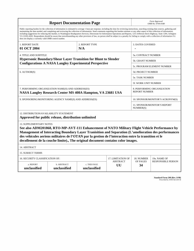
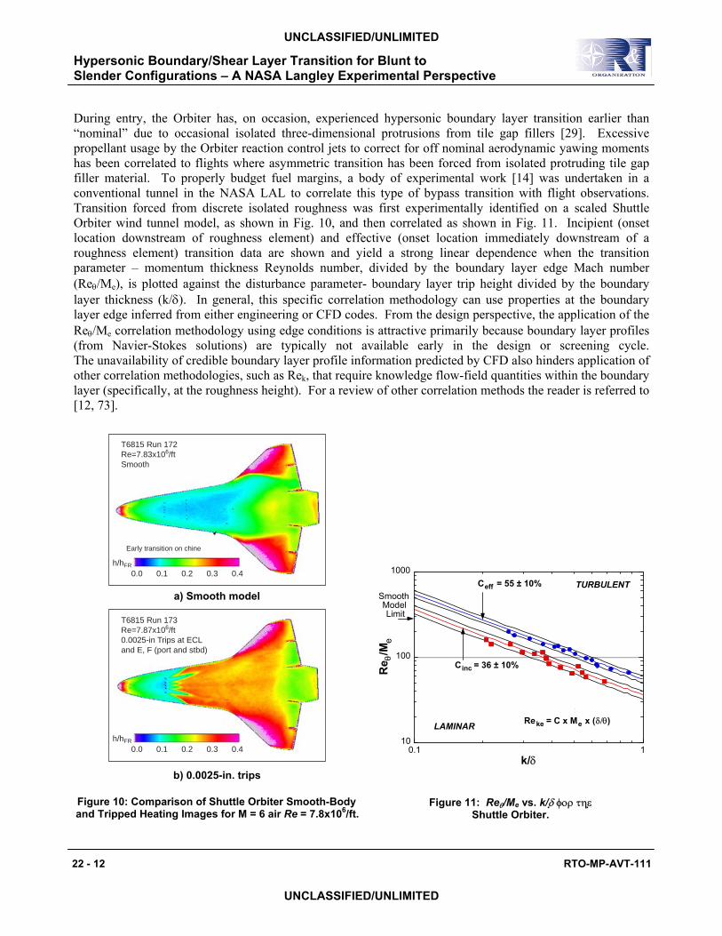
During entry, the Orbiter has, on occasion, experienced hypersonic boundary layer transition earlier than “nominal” due to occasional isolated three-dimensional protrusions from tile gap fillers [29]. Excessive propellant usage by the Orbiter reaction control jets to correct for off nominal aerodynamic yawing moments has been correlated to flights where asymmetric transition has been forced from isolated protruding tile gap filler material. To properly budget fuel margins, a body of experimental work [14] was undertaken in a conventional tunnel in the NASA LAL to correlate this type of bypass transition with flight observations. Transition forced from discrete isolated roughness was first experimentally identified on a scaled Shuttle Orbiter wind tunnel model, as shown in Fig. 10, and then correlated as shown in Fig. 11. Incipient (onset location downstream of roughness element) and effective (onset location immediately downstream of a roughness element) transition data are shown and yield a strong linear dependence when the transition parameter – momentum thickness Reynolds number, divided by the boundary layer edge Mach number (Reθ/Me), is plotted against the disturbance parameter- boundary layer trip height divided by the boundary layer thickness (k/δ). In general, this specific correlation methodology can use properties at the boundary layer edge inferred from either engineering or CFD codes. From the design perspective, the application of the Reθ/Me correlation methodology using edge conditions is attractive primarily because boundary layer profiles (from Navier-Stokes solutions) are typically not available early in the design or screening cycle. The unavailability of credible boundary layer profile information predicted by CFD also hinders application of other correlation methodologies, such as Rek, that require knowledge flow-field quantities within the boundary layer (specifically, at the roughness height). For a review of other correlation methods the reader is referred to [12, 73].
h/hFR
0.10.0 0.2 0.3 0.4
T6815 Run 172Re=7.83x10⁶/ftSmooth
Early transition on chine
a) Smooth model
h/hFR
0.10.0 0.2 0.3 0.4
T6815 Run 173Re=7.87x10⁶/ft0.0025-in Trips at ECLand E, F (port and stbd)
b) 0.0025-in. trips
10
100
1000
0.1 1
Re θ
/Me
k/δ
LAMINAR
TURBULENT
From Ref. 9: Reke = C x Me x (δ/θ)
Ceff = 55 ± 10%
Cinc = 36 ± 10%
SmoothModelLimit
Figure 10: Comparison of Shuttle Orbiter Smooth-Body and Tripped Heating Images for M = 6 air Re = 7.8x10⁶/ft.
Figure 11: Reθ/Me vs. k/δ φορ τηε Shuttle Orbiter.

Hypersonic Boundary/Shear Layer Transition for Blunt to Slender Configurations – A NASA Langley Experimental Perspective
RTO-MP-AVT-111 22 - 13
UNCLASSIFIED/UNLIMITED
UNCLASSIFIED/UNLIMITED
The practical correlation methodology based upon boundary layer edge conditions has been used to characterize an early transition event experienced in flight on STS-28 where transition was forced near Mach 18 from two isolated protruding tile gap fillers of approximately 0.4-inches in height (post flight measurement). Based upon the correlation shown in Fig. 11, an isolated surface roughness of approximately 0.4-inch would have been predicted to force “early” boundary layer transition as observed on STS-28. Similar to the Orbiter flight experience, if the distributed surface roughness of the TPS can be characterized, the design margins associated with high Mach boundary layer transition for future moderately blunt RLV designs (Shuttle-like configurations) will most likely be driven by isolated surface roughness associated with the TPS.
During the initial phase of the CAI, the media focused national attention to the possibility that wing roughness from damage incurred during ascent ultimately led to the destruction of the Orbiter. This speculation [74] often cited boundary layer transition as a possible initiating event affecting the vehicle aerodynamics and accelerating the thermal erosion of TPS tiles. Initial experimental testing [75] conducted within two weeks of the accident simulated a broad spectrum of thermal protection system damage to the Orbiter windward surface and was used to refute (aerodynamic increments were inconsistent with Columbia flight data) several hypothesized forms of thermal protection system damage, which included gouges in the windward thermal protection system tiles, breaches through the wing near the main landing gear door, and protuberances along the wing leading edge that produced asymmetric boundary layer transition. As the forensic phase of the investigation developed and the condition of recovered debris was examined, increasing emphasis was placed on identifying wing leading edge damage (partially and fully missing reinforced carbon-carbon panels, and eventually holes in the wing leading edge, with venting to the wing upper surface) that produced off-nominal side fuselage heating trends consistent with extracted Orbiter flight recorder temperature data.
It is reasonable to assume that wing damage that alters flow separation characteristics along the leading edge could have first order effects on side fuselage/OMS pod heating. While not explicitly tied to transition, the analysis and interpretation of the Shuttle leeside flow-field in the presence of wing leading edge damage was critical to the investigation. Under a nominal entry, the separated, highly three-dimensional leeside flow of the Orbiter begins to transition to turbulence near Mach number 18. In the presence of wing damage, the Orbiter leeward flow characteristics were quite likely nonlaminar during the entry of STS-107. The scenario developed during the CAI postulated that sometime after entry interface (EI) a breach into a wing RCC panel permitted the wing leading edge channel to pressurize and vent to the wing leeward surface along a designed gap running along the upper wing RCC/carrier panel interface. The wind tunnel simulations of this damage scenario, presented in Fig. 12, resulted in heating reductions that ranged from approximately 0.65 to 0.75, times the nominal undisturbed levels, and were consistent with reductions inferred from the flight data recorder (EI +350 sec). From forensic evidence, it is reasonable to assume Columbia’s wing leading edge continued to degrade during entry. Subsequent parametric testing with isolated, partially missing RCC panels along the wing leading edge clearly indicated highly localized heating on the side fuselage, which was consistent with temperature increases measured on Columbia’s side fuselage during entry. The effects of a missing wing RCC panel on the Orbiter leeside flow, as inferred from surface heating and corresponding streamline patterns, are shown in Fig. 13. Flow separation from the wing upper surface and subsequent reattachment on the side fuselage, as described by [76] is apparent from the surface oil flow streamline patterns. Side fuselage heating augmentations associated with missing RCC panels were found to range from 2 to 12, consistent with augmentations in flight (EI +550 sec). From an aerothermodynamic perspective, closure in the investigation was achieved through these wind tunnel tests [75] that emulated leeside temperature anomalies observed on Columbia due to perturbations of the leeside flow flow-field (separation and reattachment).

Hypersonic Boundary/Shear Layer Transition for Blunt to Slender Configurations – A NASA Langley Experimental Perspective
22 - 14 RTO-MP-AVT-111
UNCLASSIFIED/UNLIMITED
UNCLASSIFIED/UNLIMITED
Figure 12: Effect of Flow from Windward RCC Panel 8 Damage through Leeside Vent on Orbiter Side Fuselage Heating.
Figure 13: Postulated Orbiter Leeside Flow-Field with Leading Edge Damage.
Lessons learned from the Columbia accident regarding hypersonic boundary layer transition continue to play a prominent role in Shuttle Return-to-Flight efforts. After the release of the Columbia Accident Investigation Board’s (CAIB) final report [77], an Entry Aeroheating Panel Working Group led by NASA Johnson Space Center was formed to implement the CAIB recommendations specific to the aerothermodynamic assessment

Hypersonic Boundary/Shear Layer Transition for Blunt to Slender Configurations – A NASA Langley Experimental Perspective
RTO-MP-AVT-111 22 - 15
UNCLASSIFIED/UNLIMITED
UNCLASSIFIED/UNLIMITED
of TPS damage and repair. One objective is to provide the tools necessary for a rapid aerothermodynamic assessment capability to determine the likelihood of high Mach number boundary layer transition due to flow disturbances created from TPS damage or repair. If transition occurs above Mach 18, the Shuttle may experience unacceptably high internal structural temperatures. At present, experimental databases, represented in Fig. 14, are being developed to support the establishment of Shuttle tile damage thresholds that could trigger corrective action such as on orbit repair. Impact damage from ice or foam shed from the external tank during ascent can lead to the formation of localized cavities on the tiled surface. In the case of impact with a wing leading edge RCC panel, the resulting damage will be repaired using the patch (plug) concept shown, which will create steps (protuberances) on the surface. While the Shuttle Orbiter flight history with early boundary layer transition and supplemental wind tunnel data form the basis for the protuberance height restriction, little is known about the influences of isolated cavities. Some similarities in local flow features and physics within the damage (cavity) site may be inferred from a larger body of work, namely, the supersonic weapons store problem. In an open weapons bay, the approaching boundary layer separates from the bay leading edge and may pass over or be entrained into the weapons store area (i.e., a large “cavity”), depending on the bay dimensions. Within this large cavity, flow separation, reattachment, recirculation, unsteadiness, and transition are all possible. Naturally, a TPS damage site (cavity) on the Orbiter is at a far smaller scale, but the local flow phenomenon within the cavity remains the same. The state of the flow within the damage site likely determine the “downstream” effects on the flow transition process. In support of Shuttle Return-to-Flight, wind tunnel tests have been completed to characterize the influence of dimensions (length, width, and depth) on hypersonic transition associated with a simple rectangular cavity (analogous to a missing tile or tile array). The present data indicate cavities of a given depth are less likely to force transition downstream of the cavity than a corresponding protuberance of equivalent height. The parametric trends from the current tests also suggest that relative to a baseline rectangular cavity, an increase in length, width, and depth promotes transition downstream of the cavity earlier. Future testing will attempt to characterize the effects of cavity shape (more representative of actual impact damage), orientation (relative to the local streamlines), and location (strong pressure gradient) on transition.
Figure 14: Transition from Cavities, Protuberances, and Outgasing.

Hypersonic Boundary/Shear Layer Transition for Blunt to Slender Configurations – A NASA Langley Experimental Perspective
22 - 16 RTO-MP-AVT-111
UNCLASSIFIED/UNLIMITED
UNCLASSIFIED/UNLIMITED
Should the predicted local heating environment within a cavity necessitate a repair, an astronaut will be required to execute a difficult and risky space walk. The current tile repair material would be applied by the astronaut with a pneumatically controlled handheld applicator. The repair material must first be “smoothed” with special tools to avoid surface protrusions that may lead to transition. Furthermore, as the material is a cure-in-place ablator, the char layer formed during entry is not shape stable; swelling (protuberance) and outgasing (mass addition) into the boundary layer is likely during entry, so both affects on transition must be considered. Influences of ablation on boundary layer transition have been generally restricted to earth and planetary hypervelocity entries with vehicles having blunt heatshields; most of these applications involve massive ablation [65] from the heatshield as opposed to the isolated case corresponding to a tile repair. Ablating antennae windows found in some high performance reentry vehicles may provide insight into the influence of an isolated ablator (possibly in the presence of a cavity), but much of this information would not be available in the public domain. Isolated blowing has also been studied from an aerodynamic control perspective, but the blowing rates (relative to that from an ablating material) are generally too large to apply to the tile repair issue. Thus, synergistic with the cavity testing, wind tunnel tests were undertaken to assess the influence of blowing rates (consistent with those expected during Shuttle entry) as well as the molecular weight of the gases used to simulate the expected ablation products on hypersonic transition. As expected, the preliminary data from the current study suggest that low blowing rates associated with ablation in flight would not advance transition onset. In addition, for a fixed blowing rate, a higher molecular weight gas (3 times heavier than to air) delayed transition.
3.2.2 NASA/Lockheed: X-33 Suborbital RLV Demonstrator
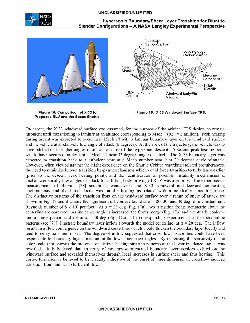
As part of the NASA Single-Stage-To-Orbit (SSTO) RLV program, the X-33 was to have been developed as a hypersonic flight technology demonstrator. The X-33 Program intended to validate key design and operational aspects of a SSTO rocket powered RLV to reduce the risk to the private sector in developing such a commercially viable system. The proposed suborbital X-33 was a slab-delta lifting body design with symmetric canted fins, twin vertical tails, and two outboard body flaps located at the rear of the fuselage. A comparison of the X-33 to its commercial counterpart, the proposed Venture Star and the Space Shuttle Orbiter is shown, Fig. 15. NASA Langley was tasked with providing experimental boundary layer transition and aeroheating data in support of the X-33 development and design. A series of wind tunnel entries in the LAL 20-Inch Mach 6 Air Tunnel was used to first determine the smooth body transition patterns, and if possible, identify possible transition mechanisms. Tests were performed to determine the effect on transition of discrete roughness elements located on and off the windward centerline; and to characterize the influence of distributed roughness in the form of a wavy wall that simulated the expected metallic TPS panel bowing in flight (due to temperature gradients across the panel). A schematic layout of the X-33 windward metallic TPS design is shown in Fig. 16. The X-33 program serves as an excellent example of the aerothermodynamic iterative process facing the vehicle designer. In the past, experimental aeroheating information via testing in hypersonic wind tunnels significantly lagged behind aerodynamics due primarily to model and instrumentation complexities associated with aerothermodynamic studies. The time frame of the X-33 program, coupled with the development of the two-color global phosphor thermography technique presented NASA Langley the first opportunity to conduct an aerodynamic and aeroheating screening/trade studies in parallel with aerodynamic development. The evolution of the X-33 configuration from the initial aerolines through the program’s eventual termination necessitated multiple entries into the LAL facilities to investigate the effects of shape changes (primarily driven by subsonic-transonic aerodynamic issues) on the X-33's aeroheating environment. Approximately 1100 tunnel runs from 16 entries in two LAL facilities were completed on four X-33 configurations over a 2 year period.
Hypersonic Boundary/Shear Layer Transition for Blunt to Slender Configurations – A NASA Langley Experimental Perspective
RTO-MP-AVT-111 22 - 17
UNCLASSIFIED/UNLIMITED
UNCLASSIFIED/UNLIMITED
Figure 15: Comparison of X-33 to Proposed RLV and the Space Shuttle.
Figure 16: X-33 Windward Surface TPS.
On ascent, the X-33 windward surface was assumed, for the purpose of the original TPS design, to remain turbulent until transitioning to laminar at an altitude corresponding to Mach 7 (ReL = 2 million). Peak heating during ascent was expected to occur near Mach 14 with a laminar boundary layer on the windward surface and the vehicle at a relatively low angle of attack (6 degrees). At the apex of the trajectory, the vehicle was to have pitched up to higher angles of attack for most of the hypersonic descent. A second peak heating point was to have occurred on descent at Mach 11 near 32 degrees angle-of-attack. The X-33 boundary layer was expected to transition back to a turbulent state at a Mach number near 9 at 20 degrees angle-of-attack. However, when viewed against the flight experience on the Shuttle Orbiter regarding isolated protuberances, the need to minimize known transition by-pass mechanisms which could force transition to turbulence earlier (prior to the descent peak heating point), and the identification of possible instability mechanisms at uncharacteristically low angles-of-attack for a lifting body or winged RLV was a priority. The experimental measurements of Horvath [78] sought to characterize the X-33 windward and leeward aeroheating environments and the initial focus was on the heating associated with a nominally smooth surface. The distinctive patterns of the transition front on the windward surface over a range of angle of attack are shown in Fig. 17 and illustrate the significant differences found at α = 20, 30, and 40 deg for a constant unit Reynolds number of 8 x 10⁶ per foot. At α = 20 deg (Fig. 17a), two transition fronts symmetric about the centerline are observed. As incidence angle is increased, the fronts merge (Fig. 17b) and eventually coalesce into a single parabolic shape at α = 40 deg (Fig. 17c). The corresponding experimental surface streamline patterns (see [78]) illustrate boundary layer inflow (towards the model centerline) at α = 20 deg. The inflow results in a flow convergence on the windward centerline, which would thicken the boundary layer locally and tend to delay transition onset. The degree of inflow suggested that crossflow instabilities could have been responsible for boundary layer transition at the lower incidence angles. By increasing the sensitivity of the color scale (not shown) the presence of distinct heating striation patterns at the lower incidence angles was revealed. It is believed that an array of streamwise-orientated boundary layer vortices existed on the windward surface and revealed themselves through local increases in surface shear and thus heating. This vortex formation is believed to be visually indicative of the onset of three-dimensional, crossflow-induced transition from laminar to turbulent flow.

Hypersonic Boundary/Shear Layer Transition for Blunt to Slender Configurations – A NASA Langley Experimental Perspective
22 - 18 RTO-MP-AVT-111
UNCLASSIFIED/UNLIMITED
UNCLASSIFIED/UNLIMITED
The significance of the isolated discrete and distributed roughness measurements was three-fold. First, the attachment line (on the X-33, along the chine) has been suggested [9] to be a region of increased sensitivity to surface roughness and a experimental test was initiated to determine if this assumption could be corroborated. Counter to the expectation of [9], the results of Berry [15] did not show any evidence of a higher sensitivity to roughness elements placed along the attachment line. In general, the off-centerline isolated roughness results for a range of angle of attack (20 <α < 40-degrees) were in very good agreement with the previously reported centerline transition correlation. Secondly, the isolated roughness transition criteria determined from the X-33 database motivated the development of an analytic method [17] that provided rapid determination of transition onset for a range of altitudes, velocities, and angles of attack. The flexible predictive approach, shown conceptually in Fig. 18 allowed for the use of any transition criteria as an input. The correlation transition parameter Reθ/Me = 250 (at x/L = 0.8 on the X-33 windward centerline) predicted via an engineering boundary layer method was used by the X-33 program to tailor the trajectory in an attempt to constrain laminar heating rates to within the capability of the metallic TPS proposed by Lockheed Martin. Third, the assessment of distributed roughness in the form of bowed panels (a wavy wall) qualitatively indicated that this form of roughness was less effective than the discrete trips of equivalent height in promoting transition. The study was pioneering in the sense of capturing the expected metallic bowed panel topology in a cast ceramic heat transfer model, but it did not attempt to address the coupled wavy (thermal deflections) and distributed surface roughness (metallic panel interfaces) effect on transition.
05
1015
Velocity, kft/s
01020304050
α, deg
0
50
100
150
200
250
300
Alti
tud
e, k
ft
Transition surface
Trajectory
LAMINAR
TURBULENT
(Reθ/Me=250 at x/L=0.8)
(Malmstrom 4)
Figure 18: X-33 Windward Transition Criterion based on Reθ/Me = 250 at x/L = 0.8 on centerline (Ref. 17).
Fig 17a. Effect of α on smooth body transition patterns for α = 20-deg, Re = 7.9x10⁶/ft, δBF = 20-deg.
Fig 17b. Effect of α on smooth body transition patterns for α = 30-deg, Re = 7.9x10⁶/ft, δBF = 20-deg.
Fig 17c. Effect of α on smooth body transition patterns for α = 40-deg, Re = 7.9x10⁶/ft, δBF = 20-deg.

Hypersonic Boundary/Shear Layer Transition for Blunt to Slender Configurations – A NASA Langley Experimental Perspective
RTO-MP-AVT-111
UNCLASSIFIED/UNLIMITED
UNCLASSIFIED
3.2.3 NASA/ESA: X-38 Crew Return Vehicle The objective of the NASA X-38 program was to demonstrate an autonomous return from low Earth orbit of an experimental flight test vehicle, with the ultimate goal of supporting the design and development of an operational Crew Return Vehicle (CRV) for the International Space Station (ISS). The first test flight of a full-scale CRV technology demonstrator was to have validated essential technologies, including aerodynamic performance and aeroheating characteristics via thermal protection system (TPS) performance over the entire mission profile, as required for safely returning space station crew members to Earth with precision landing in the event of medical emergency or serious ISS mechanical problems and Shuttle Orbiter nonavailabilNASA JSC and its evolution is shown in Fig.19. Thoriginally developed and flown during the U.S. Air Forc[81] projects in the mid-1960s and early 1970s; and was(higher L/D translates to larger cross range capabilitefficiency (room for all station crew if necessary). Hiwas imperative for the design, and most importantaerodynamic data book upon which the vehicle wouldquantification of aero-heating levels and loads for desirequired. A synergistic combination of ground-based dynamics (CFD) predictions was performed to generafluid dynamic data/information necessary for the deexperimental rapid assessment methodology demonstrmeasurements in hypersonic wind tunnels were obtainecapability to perform vehicle assessment (i.e., screeninstudies based on both aerodynamic and aeroheating infor
The thermal environment associated with the X-38 bodthe complex three-dimensional flow-field and resultiThe windward flap temperatures in flight will be significflow separations, shear-layer transition, multiple shock pand flow expansion and acceleration over the flap edgdesigned as a hot structure and were to be manufacturAssuming fully turbulent flow, early estimates of flap provide an adequate thermal margin; however, vesignificantly reduced this margin. A comprehensive comore accurately assess the heating environment associaflaps and to determine if the thermal margin was exceedthe body fuselage and flap chord (y/b = 0.2), Fig.20, characteristic of transitional flow. Turbulence forced wseparation reduced the extent of separation and loweredbeen previously observed with tests on the X-33. The bthe vicinity of flow reattachment on the deflected body
Figure 19: Shape Evolution of 0.0175-Scale X-38 Models.
22 - 19
/UNLIMITED
ity. The initial X-38 shape (Rev 3.1) proposed by is initial shape was based on a lifting body concept e PRIME (X-23/SV-5D) [79,80] and PILOT (X-24A)
selected by JSC for its relatively high hypersonic L/D y and shorter loiter times in orbit) and volumetric gh fidelity, highly credible aerodynamic information ly, the development/generation of the X-38 flight fly for the entire entry trajectory; and high fidelity gn of the critical thermal protection system was also testing Horvath et. al. [19] and computational fluid te crucial hypersonic aerodynamic, aeroheating, and sign and flight of the X-38 vehicle. Using the ated in the X-33 program, quantitative aeroheating d thereby providing X-38 vehicle designers with the g) and optimization of outer mold line (OML) trade mation.
y flaps was a high-priority a design challenge due to ng high surface temperatures anticipated in flight. antly influenced by several factors: three-dimensional rocessing of the flow (bow, separation, reattachment), es and through the split gap. The X-38 flaps were ed from C/SiC, a ceramic matrix composite (CMC). thermal loads suggested that CMC technology could hicle weight growth and trajectory modifications mputational and experimental effort was initiated to ted with the windward surface of the deflected body ed. Wind tunnel heating distributions measured along revealed an “overshoot” in heating at reattachment, ith a discrete roughness element placed upstream of
the heating on the flap. The same phenomenon had enchmark transitional heating measurements made in flaps of the X-38 revealed deficiencies in the initial

Hypersonic Boundary/Shear Layer Transition for Blunt to Slender Configurations – A NASA Langley Experimental Perspective
22 - 20 RTO-MP-AVT-111
UNCLASSIFIED/UNLIMITED
UNCLASSIFIED/UNLIMITED
engineering model used by NASA JSC to assess local TPS thermal margins of the hot structure body flap itself in flight. The global heating measurements on the flap did not reveal the presence of Gortler vortices, as is sometimes evident downstream of flow reattachment.
0
0.2
0.4
0.6
0.8
1
0 0.2 0.4 0.6 0.8 1
Nor
mal
ized
hea
ting
X/L
Tripped (k = 0.005-in)
Untripped
Figure 20: Effect of Boundary Layer Trip on X-38 Rev 3.1 Longitudinal Body Flap Heating Distribution. M∞ = 6 Air, α = 40 deg, Re∞, L = 4 x 10⁶, δBF = 25 deg.
The acreage TPS of the X-38 was based on a derivative of the Shuttle Orbiter ceramic-tile. As the proposed lifting body flight entry trajectory was similar to the Shuttle Orbiter., it was assumed that distributed roughness effects (from randomly distributed tile-to-tile misalignments) would be no worse than with the Shuttle. Thus, an isolated roughness test was undertaken to define the discrete step/gap tolerances between the X-38 TPS carrier panels (each panel consisted of an array of individual ceramic tiles which was attached to the vehicle frame) that would potentially initiate early high Mach number boundary layer transition. The isolated discrete roughness test led by Horvath et. al. [17] supported the development of a boundary layer transition correlation that was used to establish TPS carrier panel manufacturing and attachment guidelines for windward surface step and gap tolerances. Consistent with the correlation methodology developed for the Shuttle and later for the X-33, the size, height, and location of discrete surface roughness were methodically varied as was free-stream unit Reynolds number to produce transitional and fully turbulent flow (see Berry et. al. [14] for complete details). Laminar boundary layer edge conditions at the trip location were computed by using a boundary-layer code [82] (LATCH) for a range of Reynolds numbers. Figure 21 illustrates the isolated roughness results along the X-38 centerline for Mach 6 in air and an angle of attack of 40 deg. Correlation data obtained in the LAL 20-Inch Mach 6 Air Tunnel from the X-33 and Shuttle Orbiter transition studies are included in Fig. 21 for comparative purposes. The correlations shown in Fig. 21 suggest that when a consistent computational method is used, transition datasets obtained on several different moderately blunt configurations at various angles of attack can be correlated using properties based on laminar boundary layer edge conditions. This simple correlation applied at wind tunnel conditions appears applicable to moderately blunt lifting body configurations in the same class of the Orbiter, as long as a consistent computational approach is used to apply the correlation.

Hypersonic Boundary/Shear Layer Transition for Blunt to Slender Configurations – A NASA Langley Experimental Perspective
RTO-MP-AVT-111 22 - 21
UNCLASSIFIED/UNLIMITED
UNCLASSIFIED/UNLIMITED
1
10
100
1000
0.1 1 10
Centerline Effective Transition ResultsComputed with LATCH
θ/Me
k/δ
LAMINAR
TURBULENT
Ceff = 70 ± 20%Shuttle α = 40-degX-33 α = 20-deg
X-33 α = 40-degX-38 α = 40-deg
X-33 α = 30-deg
Figure 21: Comparison of Orbiter Effective Data Computed with LATCH to X-33 and X-38 Results.
3.2 Slender Configurations The designer of an extended cruise hypersonic air breather vehicle faces the same basic challenges as the designers of entry vehicles, that is, to minimize heat rates and loads plus additional challenges associated with boundary layer transition. Uncertainties in drag prediction [83] and propulsion system efficiencies [84] (e.g., inlet mass capture, fuel mixing) resulting from the presence or absence of boundary layer transition could substantially impact vehicle performance. For airframe-integrated scramjet engines, the forebody ahead of the inlet is designed to process and precondition the flow that will be ingested by the inlet. As shown conceptually in Fig. 22, a full-scale air-breathing vehicle will likely have competing transition mechanisms (e.g., crossflow, Goertler, 1st mode, 2nd mode) in the forebody boundary layer that will lead to flow transition ahead of the inlet. While turbulent flow is desirable within the scramjet to mitigate flow separations, turbulence along the entire forebody compression surface is generally not wanted due to increased drag and higher overall heating loads and hence, increased TPS requirements.
Figure 22: Transition Mechanisms for Airbreathing Concepts.

Hypersonic Boundary/Shear Layer Transition for Blunt to Slender Configurations – A NASA Langley Experimental Perspective
22 - 22 RTO-MP-AVT-111
UNCLASSIFIED/UNLIMITED
UNCLASSIFIED/UNLIMITED
3.3.1 NASA X-43A (Hyper-X)
The National Aerospace Plane (NASP) program that began in the mid-1980s started a renaissance in hypersonic research that culminated in the successful demonstration in March 2004 of airbreathing scramjet technologies on the Hyper-X (X-43A) vehicle. The vehicle shape of the Hyper-X is reminiscent of industry concepts proposed under the U. S. National AeroSpace Plane (NASP) program. The windward forebody of the Hyper-X is approximately 6-ft long and is characterized by a thin leading edge (Rn = 0.03-in) and 3 flat ramps that provide a series of discrete, non-isentropic flow compressions for the scramjet engine. While cruising at the nominal angle of attack of 2-deg, the first forebody ramp provided an initial 4.5-deg of compression, followed by a second and third ramp that provided an additional 5.5-deg, and 3-deg of compression, respectively. Outboard of the flat ramps are the chines, which are designed to minimize three-dimensional effects and flow spillage. On a subscale demonstrator vehicle such as the Hyper-X, the boundary layer on the shorter forebody length is less likely to naturally transition prior to the engine inlet. An analysis of the Hyper-X forebody using the hypersonic boundary layer transition criteria [85] developed during the NASP program suggested that the vehicle forebody will be fully laminar during the scramjet test period for the Mach 7 flight. The results from this analysis are detailed in [86]. Figure 23 is a comparison of the baseline (no trip) results on the Hyper-X forebody between Mach 6 and Mach 10 for the nominal wind tunnel condition of α = 2-deg and Re = 2.2x10⁶/ft. The Mach 10 results (Fig. 23, right side) correspond to a closed cowl. The heating results show the first two ramps to be laminar, with transition onset occurring on the last ramp. Transition onset just prior to the end of the first ramp was desired to minimize compression corner separation and lateral flow spillage, and to provide a fully turbulent boundary layer at the inlet. Thus, even in the environment of conventional (non-quiet) hypersonic wind tunnels, where coupling of flow disturbances to the boundary layer may occur, forced transition via tripping was required at nominal conditions (Re, M) representative of flight. Developed through a series of wind tunnel screening tests by Berry [22], the Hyper-X program successfully used a fixed (nonretractable) array of swept ramp surface protuberances to force turbulent flow on the forebody in a controlled and predictable manner for the Mach 7 flight.
Figure 23: Natural Transition Results from the Mach 6 and 10 Tunnels.
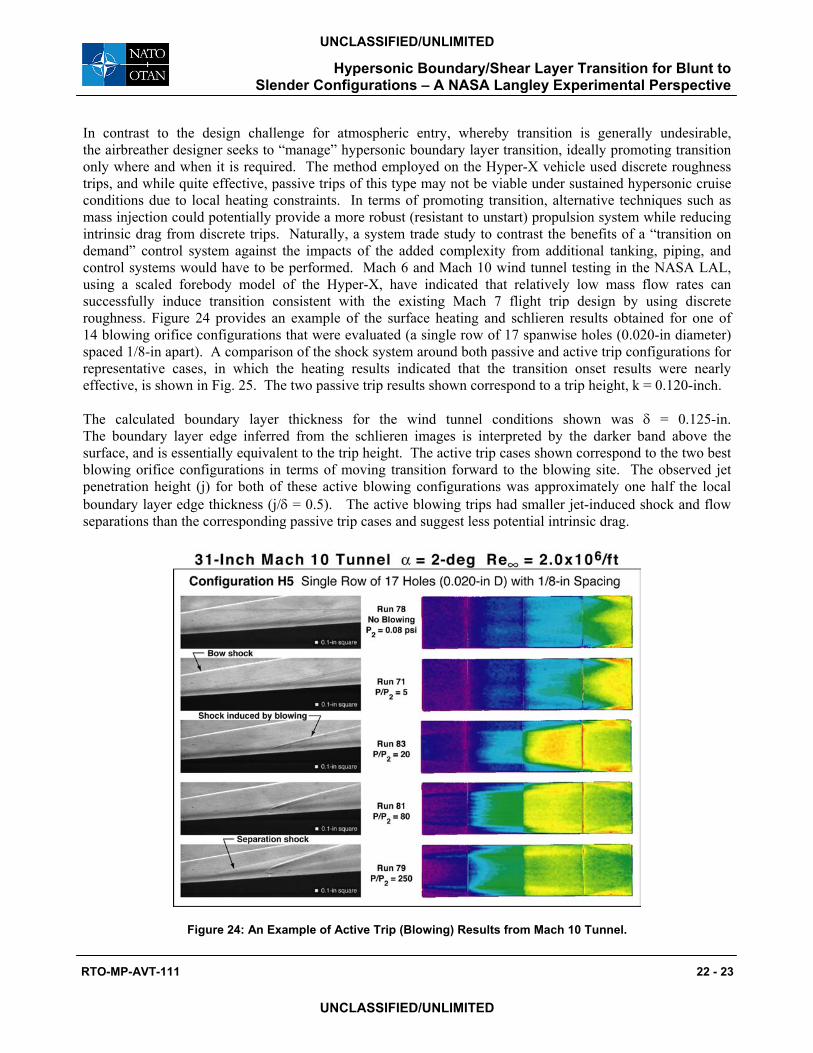
Hypersonic Boundary/Shear Layer Transition for Blunt to Slender Configurations – A NASA Langley Experimental Perspective
RTO-MP-AVT-111 22 - 23
UNCLASSIFIED/UNLIMITED
UNCLASSIFIED/UNLIMITED
In contrast to the design challenge for atmospheric entry, whereby transition is generally undesirable, the airbreather designer seeks to “manage” hypersonic boundary layer transition, ideally promoting transition only where and when it is required. The method employed on the Hyper-X vehicle used discrete roughness trips, and while quite effective, passive trips of this type may not be viable under sustained hypersonic cruise conditions due to local heating constraints. In terms of promoting transition, alternative techniques such as mass injection could potentially provide a more robust (resistant to unstart) propulsion system while reducing intrinsic drag from discrete trips. Naturally, a system trade study to contrast the benefits of a “transition on demand” control system against the impacts of the added complexity from additional tanking, piping, and control systems would have to be performed. Mach 6 and Mach 10 wind tunnel testing in the NASA LAL, using a scaled forebody model of the Hyper-X, have indicated that relatively low mass flow rates can successfully induce transition consistent with the existing Mach 7 flight trip design by using discrete roughness. Figure 24 provides an example of the surface heating and schlieren results obtained for one of 14 blowing orifice configurations that were evaluated (a single row of 17 spanwise holes (0.020-in diameter) spaced 1/8-in apart). A comparison of the shock system around both passive and active trip configurations for representative cases, in which the heating results indicated that the transition onset results were nearly effective, is shown in Fig. 25. The two passive trip results shown correspond to a trip height, k = 0.120-inch.
The calculated boundary layer thickness for the wind tunnel conditions shown was δ = 0.125-in. The boundary layer edge inferred from the schlieren images is interpreted by the darker band above the surface, and is essentially equivalent to the trip height. The active trip cases shown correspond to the two best blowing orifice configurations in terms of moving transition forward to the blowing site. The observed jet penetration height (j) for both of these active blowing configurations was approximately one half the local boundary layer edge thickness (j/δ = 0.5). The active blowing trips had smaller jet-induced shock and flow separations than the corresponding passive trip cases and suggest less potential intrinsic drag.
Figure 24: An Example of Active Trip (Blowing) Results from Mach 10 Tunnel.
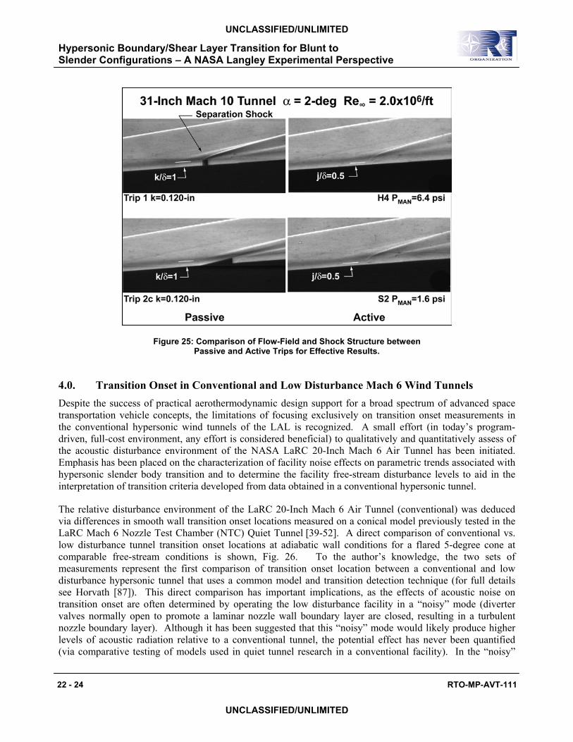
Hypersonic Boundary/Shear Layer Transition for Blunt to Slender Configurations – A NASA Langley Experimental Perspective
22 - 24 RTO-MP-AVT-111
UNCLASSIFIED/UNLIMITED
UNCLASSIFIED/UNLIMITED
Figure 25: Comparison of Flow-Field and Shock Structure between Passive and Active Trips for Effective Results.
4.0. Transition Onset in Conventional and Low Disturbance Mach 6 Wind Tunnels Despite the success of practical aerothermodynamic design support for a broad spectrum of advanced space transportation vehicle concepts, the limitations of focusing exclusively on transition onset measurements in the conventional hypersonic wind tunnels of the LAL is recognized. A small effort (in today’s program-driven, full-cost environment, any effort is considered beneficial) to qualitatively and quantitatively assess of the acoustic disturbance environment of the NASA LaRC 20-Inch Mach 6 Air Tunnel has been initiated. Emphasis has been placed on the characterization of facility noise effects on parametric trends associated with hypersonic slender body transition and to determine the facility free-stream disturbance levels to aid in the interpretation of transition criteria developed from data obtained in a conventional hypersonic tunnel.
The relative disturbance environment of the LaRC 20-Inch Mach 6 Air Tunnel (conventional) was deduced via differences in smooth wall transition onset locations measured on a conical model previously tested in the LaRC Mach 6 Nozzle Test Chamber (NTC) Quiet Tunnel [39-52]. A direct comparison of conventional vs. low disturbance tunnel transition onset locations at adiabatic wall conditions for a flared 5-degree cone at comparable free-stream conditions is shown, Fig. 26. To the author’s knowledge, the two sets of measurements represent the first comparison of transition onset location between a conventional and low disturbance hypersonic tunnel that uses a common model and transition detection technique (for full details see Horvath [87]). This direct comparison has important implications, as the effects of acoustic noise on transition onset are often determined by operating the low disturbance facility in a “noisy” mode (diverter valves normally open to promote a laminar nozzle wall boundary layer are closed, resulting in a turbulent nozzle boundary layer). Although it has been suggested that this “noisy” mode would likely produce higher levels of acoustic radiation relative to a conventional tunnel, the potential effect has never been quantified (via comparative testing of models used in quiet tunnel research in a conventional facility). In the “noisy”

Hypersonic Boundary/Shear Layer Transition for Blunt to Slender Configurations – A NASA Langley Experimental Perspective
RTO-MP-AVT-111 22 - 25
UNCLASSIFIED/UNLIMITED
UNCLASSIFIED/UNLIMITED
mode of the hypersonic low disturbance tunnel, transition onset occurred earlier than that measured in the conventional hypersonic tunnel, Fig. 26, which suggests higher levels of free stream acoustic radiation relative to this conventional tunnel. The transition onset Reynolds number under low-disturbance conditions is a factor of 1.3 greater than measured on the flared cone in the LaRC conventional hypersonic tunnel and a factor of 1.6 relative to the flared cone run in the quiet tunnel run “noisy.”
0.5
0.6
0.7
0.8
0.9
1
0 5 10 15 20 25
Mach 6 NTC low disturbanceMach 6 NTC noisy
20-in Mach 6 (conventional )
T w/T
o
x, inches
R
eT =
2.8
9 x
106
Re
T = 3
.84
x 10
6
5 deg cone flare
Re
T = 2
.34
x 10
6
Figure 26: Comparison of Present Smooth Body Transition Onset Locations to that Obtained in the NASA LaRC M=6 NTC Quiet Tunnel at Low and High Disturbance Levels. M∞=6, Re∞=2.8 x 10⁶/ft, α=0 deg, Rn=0.0001-in.
Recent measurement of free-steam noise levels in the LaRC 20-Inch Mach 6 Air Tunnel appears to explain the differences in transition onset locations. Quantitative rms free stream noise levels in the LaRC 20-Inch Mach 6 Air Tunnel obtained with a constant voltage anemometer (CVA) and a hybrid constant current anemometer (CCA) have been recently measured [88]. At reservoir conditions corresponding to conditions run in the low disturbance tunnel (Po = 130 psi, To = 350 degree F), the CCA measurements yielded mass flux and total temperature fluctuations of 0.83% and 0.17%, respectively. The corresponding fluctuations from the CVA measurements were determined to be somewhat lower at 0.74% and 0.12%. These measured mass flux and temperature fluctuations levels are between those previously inferred in the LaRC Mach 6 Nozzle Test Chamber (NTC) Quiet Tunnel when operated in its noisy mode and its low disturbance mode. Thus, if the second mode disturbance was dominant on the flared cone model when it was tested in the conventional tunnel, the free-steam noise levels between the two facilities would appear to explain the differences in transition onset observed in these series of tests.
While the present conventional tunnel experimental data set has permitted direct comparison of transition onset to that measured in a hypersonic low disturbance tunnel, the lack of a one-to-one correspondence in terms of a stability experiment still exists. Navier-Stokes mean flow computations and linear stability analyses were conducted to assess the experimental transition onset results and have indicated N factors associated with transition onset are approximately a factor of 2 lower than those inferred from the corresponding low disturbance tunnel measurements. Second mode quasi-parallel Linear Stability Theory

Hypersonic Boundary/Shear Layer Transition for Blunt to Slender Configurations – A NASA Langley Experimental Perspective
22 - 26 RTO-MP-AVT-111
UNCLASSIFIED/UNLIMITED
UNCLASSIFIED/UNLIMITED
(LST) N-factors of various disturbance frequencies (ranging from 20 to 340 kHz) are shown in Fig. 27 for adiabatic wall conditions. The most unstable frequency under adiabatic conditions was predicted at 230kHz and is consistent with earlier flare cone stability predictions made by Balakumar [54]. The N-factor value at the measured transition onset location for this frequency was about 3.8 for the present investigation, as compared to a value of about 7.8 under low disturbance conditions. The presence of both first and second mode disturbances on the conical models tested in the conventional tunnel is likely, but cannot be verified at the present time because hot-wire measurements in the boundary layer were not attempted. Several possible reasons have been suggested to explain the disparity in N-factor between the low-disturbance and conventional wind tunnel environment. The differences in measured transition onset could be attributed to different transition mechanisms in the two experiments (e.g., first mode vs. second mode), as the N factor for the most unstable first mode frequency was not much smaller than that predicted for the second mode (see [87]), but such an explanation is purely conjecture. A small N-factor at transition onset may also suggest that early nonlinear interaction could be present in the conventional wind tunnel due to a higher disturbance environment. An earlier investigation [89] using nonlinear PSE indicated that nonlinear effects were important for the Mach 8 sharp cone experiment conducted by Stetson [90]. For the slender cone tests, nonlinear interactions involving both second-mode and asymmetric first-mode disturbances may contribute to transition. It is also possible that transition in the conventional tunnel may be the result of nonlinear mode interactions [56], and interpretation of the results based on linear stability theory may not be adequate.
0 5 10 15 200
1
2
3
4
5
6
7
8
9
10
11
12
13
14
15
Quiet tunneltransition
Conventionaltunnel transition
x, inches
N
N = 7.8
N = 3.8
230kHz
Range of frequencies = 20 - 340kHz
Figure 27: Flared Cone Second Mode Transition N-factor Values for Present Mach 6 Transition Onset Location Relative to those Obtained in the NASA LaRC M=6 NTC Quiet Tunnel
at a Low Disturbance Level, M∞=6, Re∞=2.8 x 10⁶/ft, α=0 deg, Rn=0.0001-in.
5.0 SUMMARY
Heating augmentations and temperature increases resulting from boundary layer/shear layer transition during hypersonic flight through the atmosphere of Earth or other planets impose critical constraints on the design of vehicle thermal protection systems. Laminar-to-turbulent transition effects on local surface heat transfer determine thermal protection system material selection, placement, and thickness. In terms of vehicle

Hypersonic Boundary/Shear Layer Transition for Blunt to Slender Configurations – A NASA Langley Experimental Perspective
RTO-MP-AVT-111 22 - 27
UNCLASSIFIED/UNLIMITED
UNCLASSIFIED/UNLIMITED
performance, boundary layer transition can influence vehicle aerodynamics (e.g., increased drag, roll and yaw increments when transition occurs asymmetrically) and scramjet propulsion system performance (mitigation of flow separations). The development of computational tools for the reliable and rapid prediction of boundary layer transition on complex vehicle shapes, however, continues to be hindered by the lack of a practical capability to model the complex physics associated with the transition process. Thus, the vehicle designer has no reliable, practical, and timely numerical method of predicting when and how transition will occur in hypersonic cruise or in flight during atmospheric entry; and if it occurs, how to quantify its impact on the local and acreage environments particularly those associated with flow separation and/or reattachment.
The present paper highlights recent hypersonic boundary/shear layer transition studies in NASA Langley Research Center’s conventional hypersonic wind tunnels (as opposed to high enthalpy, impulse facilities) in support of Agency access-to-space and planetary entry programs. Configurations of interest cover a broad spectrum of very blunt to very slender vehicles and include: blunt high-drag planetary aerocapture/entry vehicles; moderately blunt reusable and partially reusable crew launch/return vehicles such as the Shuttle Orbiter, X-38, and single-stage-to-orbit rocket powered concepts such as the X-33; and slender hypersonic cruise vehicles such as the Hyper-X. Advancements in rapid model fabrication methods and global qualitative/quantitative heat transfer measurement techniques have permitted the experimental hypersonic aerothermodynamicist to have a practical and significant impact on the design process of these advanced space transportation and planetary entry vehicles.
Some of the biggest impacts on vehicle design have included: (1) Development of an experimentally derived hypersonic boundary layer transition criterion that was applicable over a range of angle of attack and location on the vehicle. The transition criterion was incorporated into an analytical method used to predict hypersonic boundary layer transition over a range of trajectory parameter space (i.e., angle of attack, altitude, velocity) for Shuttle Orbiter-like vehicles (i.e., X-33, X-38). The transition correlation was also used to establish manufacturing step and gap tolerances associated with a thermal protection systems of the X-33 and X-38. (2) Refinement of a wake closure correlation applicable to blunt high-drag planetary entry vehicles. The accurate prediction of blunt body near wake flow structure is an essential part of the design process because the usable volume for payload placement behind a heatshield is generally constrained by wake closure and the position of the wake free shear layer. Experimental wake closure and base heating measurements under laminar, transitional, and turbulent conditions indicated flow impingement on a proposed Mars Sample Return Orbiter which necessitated the redesign of an unprotected payload that resided in the relatively quiescent region behind the forebody heatshield. (3) Improvement in an engineering model used to assess the thermal margin of the X-38 body flap in the presence of a separating/reattaching transitional flow (nonlaminar but not fully turbulent). The experimental benchmark transitional heating measurements indicated an approximate 30% increase in local heating to the flap relative to the corresponding fully turbulent heating values.
Despite the success of practical aerothermodynamic design support for a broad spectrum of advanced space transportation vehicle concepts, the limitations of focusing exclusively on transition measurements in the conventional hypersonic wind tunnels of the LAL is recognized. Efforts have been made to qualitatively and quantitatively assess of the acoustic disturbance environment of the NASA LaRC 20-Inch Mach 6 Air Tunnel. Emphasis has been placed on the characterization of facility noise effects on parametric trends associated with hypersonic slender body transition and to determine the facility free-stream disturbance levels to aid in the interpretation of transition criteria developed from data obtained in a conventional hypersonic tunnel. Measurements highlighted in this paper represent the first comparison of transition onset location between a conventional and low disturbance hypersonic tunnel using a common model (5 degree flared cone) and transition detection technique. Comparison of quantitative free stream mass and temperature fluctuations

Hypersonic Boundary/Shear Layer Transition for Blunt to Slender Configurations – A NASA Langley Experimental Perspective
22 - 28 RTO-MP-AVT-111
UNCLASSIFIED/UNLIMITED
UNCLASSIFIED/UNLIMITED
and transition onset location on the cone between the conventional and low disturbance Mach 6 facilities suggests the free stream acoustic radiation in the conventional tunnel is lower than what is typically present when low disturbance tunnels are run “noisy”.
Until a truly “smooth” thermal protection system for advanced space transportation and planetary entry vehicles is developed (i.e., elimination of steps, gaps), and/or a credible numerical approach to hypersonic boundary transition prediction is identified that can be implemented in a rapid assessment framework, vehicle designers will continue to rely heavily on empirically transition prediction strategies derived from ground-based measurements. Regardless of the presence of thermal protection system roughness, complex vehicle shapes will continue to present the vehicle designer with the challenge of predicting shear layer transition in highly separated/reattaching flows. Since duplication of all flight conditions is not possible via ground-based testing, and present numerical techniques are not practical for the design process where transition and flow separation/reattachment is concerned, the highest confidence level in the assessment of the flight aerothermodynamic environment will continue to be achieved through the synergistic application of both.
6.0. REFERENCES
[1] Miller, C.G., “Langley Hypersonic Aerodynamic/Aerothermodynamic Testing Capabilities - Present and Future,” AIAA Paper 98-2600, June, 1998.
[2] Micol, J.R., “Langley Aerothermodynamic Facilities Complex: Enhancements and Testing Capabilities,” AIAA Paper 98-0147, January, 1998.
[3] Merski, N.R., "Global Aeroheating Wind-Tunnel Measurements Using Improved Two-Color Phosphor Thermography Method" Journal of Spacecraft and Rockets, 36, No. 2, pp. 160-170.
[4] Merski, N.R., "Reduction and Analysis of Phosphor Thermography Data With the IHEAT Software Package," AIAA Paper 98-0712, January, 1998.
[5] Wurster, K.E., “An Assessment of the Impact of Transition on Advanced Winged Entry Vehicle Thermal Protection System Mass,” AIAA Paper 81-1090, June 1981.
[6] Stetson, K.F., “Hypersonic Transition Testing in Wind Tunnels,” Instability and Transition, Spinger-Verlag, N.Y., Vol., 1, pp. 91-97, 1990.
[7] Balakumar, P., Zhao, H., and Atkins, H., “Stability of Hpersonic Boundary Layers Over a Compression Corner,” AIAA Paper 2002-2848, 2002.
[8] Zhong, X., “Direct Numerical Simulation of 3-D Hypersonic Boundary Layer Receptivity to Freestream Disturbances,” AIAA Paper 98-0533, 1998.
[9] Poll, D.I., “Laminar-Turbulent Transition,” AGARD Advisory Report 319, Vol.1, 1996.
[10] Takeshi, I., Randall, L.A., and Schneider, S.P., “Effect of Freestream Noise on Roughness-Induced Boundary-Layer Transition for a Scramjet Inlet,” AIAA Paper 2000-0284, January, 2000.
[11] Dietz, A.J., “Boundary-Layer Receptivity to Transient Convected Disturbances” AIAA Journal, Vol. 36, No. 7, July, 1998.

Hypersonic Boundary/Shear Layer Transition for Blunt to Slender Configurations – A NASA Langley Experimental Perspective
RTO-MP-AVT-111 22 - 29
UNCLASSIFIED/UNLIMITED
UNCLASSIFIED/UNLIMITED
[12] Reda, D.C., “Review and Synthesis of Roughness-Dominated Transition Correlations for Reentry Applications,” Journal of Spacecraft and Rockets, Vol. 39, No. 2, March-April, 2002, pp. 161-167.
[13] Berry, S.A., Bouslog, S.A., Brauckmann, G.J., and Caram, J.M., “Shuttle Orbiter Experimental Boundary-Layer Transition Results with Isolated Roughness,” Journal of Spacecraft and Rockets, Vol. 35, No. 3, 1998, pp. 241-248.
[14] Berry, S.A., “Recent Shuttle Transition Results in the LaRC 20-Inch Mach 6 Tunnel,” AIAA Paper 2002-2744, June, 2002.
[15] Berry, S.A., Horvath, T.J., Hollis, B.R., Thompson. R.A., and Hamilton, H.H., “X-33 Hypersonic Boundary Layer Transition,” Journal of Spacecraft and Rockets, Vol. 38, No. 5, 2001, pp. 646-657.
[16] Thompson, R,A., Hamilton, H.H. II, Berry, S.A., and Horvath, T.J., “Hypersonic Boundary Layer Transition for X-33 Phase II Vehicle,” AIAA Paper 98-0867, January, 1998.
[17] Thompson, R.A., “Review of X-33 Hypersonic Aerodynamic and Aerothermodynamic Development,” ICA 0323, August, 2000.
[18] Berry, S.A., Horvath, T.J., DiFulvio, M., Glass, C., and Merski, N.R., “X-34 Experimental Aeroheating at Mach 6 and 10,” Journal of Spacecraft and Rockets, Vol. 36, No. 2, 1998, pp. 171-178.
[19] Horvath, T.J., Berry, S.A., Merski, N.R., and Fitzgerald, S.M., “X-38 Experimental Aerothermodynamics,” Journal of Spacecraft and Rockets, Vol. 41, No. 2, 2004, pp. 272-292.
[20] Berry, S.A., Horvath, T.J., Weilmuenster, K.J., Alter, S.J., and Merski, N.R., “X-38 Experimental Aeroheating at Mach 10,” Journal of Spacecraft and Rockets, Vol. 41, No. 2, 2004, pp. 293-301.
[21] Berry, S.A., Horvath, T.J., Roback, V.E., and Williams, G.B., “Results of Aerothermodynamic and Boundary Layer Transition Testing of 0.0362-Scale X-38 (Rev 3.1) Vehicle in NASA Langley 20-Inch Mach 6 Tunnel,” NASA TM 112857, September, 1997.
[22] Berry, S.A., Auslander, A.H., Dilley, A.D., and Calleja, J.F., “Hypersonic Boundary-Layer Trip Development for Hyper-X,” Journal of Spacecraft and Rockets, Vol. 38, No. 6, 2001, pp. 853-864.
[23] Berry, S.A., Nowak, R.J., and Horvath, T.J., “Boundary Layer Control for Hypersonic Airbreathing Vehicles,” AIAA Paper 2004-2246, June, 2004.
[24] Nance, R.P., Hollis, B.R., Horvath, T.J., Alter, S.J., and Hassan, H.A., “Computational Study of Hypersonic Transitional Wake Flow,” Journal of Thermophysics and Heat Transfer, Vol. 13, No. 2, April-June 1999.
[25] Horvath, T.J., Cheatwood, F.M., Wilmoth, R.G., and Alter, S.J., “Wake Closure Characteristics and Afterbody Heating On a Mars Sample Return Orbiter,” Innovative Transportation Systems for Exploration of the Solar System and Beyond. STAIF /AIP Conference proceedings, Vol. 608, February, 2002, pp. 318-336.
[26] Horvath, T.J., McGinley, C.B., and Hannemann, K., “Blunt Body Near Wake Flow Field at Mach 6,” AIAA Paper 96-1935, June, 1996.

Hypersonic Boundary/Shear Layer Transition for Blunt to Slender Configurations – A NASA Langley Experimental Perspective
22 - 30 RTO-MP-AVT-111
UNCLASSIFIED/UNLIMITED
UNCLASSIFIED/UNLIMITED
[27] Cheatwood, F.M., Merski, N.R., Riley, C.J., and Mitcheltree, R.A., “Aerothermodynamic Environment Definition for the Genesis Sample Return Capsule,” AIAA Paper 2001-2889, June, 2001.
[28] Hollis, B.R., and Liechty, D.S., “Boundary Layer Transition Correlations and Aeroheating Predictions for Mars Smart Lander,” AIAA Paper 2002-2745, June, 2002.
[29] Bouslog, S.A., An, M.Y., and Derry, S.M., “Orbiter Windward-Surface Boundary-Layer Transition Flight Data,” NASA CP 3248 Part 2, April, 1995.
[30] Michael, Y.A., Wang, K.C., Campbell, C.H., and Pelly, R.L., “Space Shuttle Orbiter Aerodynamics Induced by Asymmetric Boundary Layer Transition,” AIAA Paper 1996-0808, January, 1996.
[31] Bouslog. S.A., Moore, B., Lawson, I., and Sawyer, J.W., “X-33 Metallic TPS Tests in NASA-LaRC High Temperature Tunnel,” AIAA Paper 99-1045, January, 1999.
[32] Palmer, G., Kontinos, D., and Sherman, B., “Surface Heating Effects of X-33 Vehicle TPS Panel Bowing, Steps, and Gaps,” AIAA Paper 98-0865, January, 1998.
[33] Schneider, S.P., “Effects of High-Speed Tunnel Noise on Laminar-Turbulent Transition,” Journal of Spacecraft and Rockets, Vol. 38, No. 3, 2001, pp. 323-333.
[34] Beckwith, I.E., and Miller, C.G., “Aerothermodynamics and Transition in High Speed Wind Tunnels at NASA LaRC,” Annual Reviews of Fluid Mechanics, Vol. 22, 1990.
[35] Beckwith, I.E., Chen, F.J., and Malik, M.R., “Transition Research in the Mach 3.5 Low-Disturbance Wind Tunnel and Comparisons of Data with Theory,” SAE 892379, September, 1989.
[36] Chen, F.-J., Malik, M.R., and Beckwith, I.E., “Boundary-Layer Transition on a Cone and Flat Plate at Mach 3.5,” AIAA Journal, Vol. 27, No. 6, June, 1989, pp. 687-693.
[37] King, R.A., “Three-Dimensional Boundary-Layer Transition on a Cone at Mach 3.5,” Experiments in Fluids, Vol. 13, 1992, pp. 305-314.
[38] Chen, F.-J., “Boundary-Layer Transition Extent Measurements on a Cone and Flat Plate at Mach 3.5,” AIAA Paper 93-0342, January, 1993.
[39] Wilkinson, S.P., “A Review of Hypersonic Boundary-Layer Stability Experiments in a Mach 6 Wind Tunnel,” AIAA Paper 97-1819, June, 1997.
[40] Blanchard A.E., Lachowicz J.T., and Wilkinson S.P., “NASA Langley Mach 6 Quiet Wind Tunnel Performance,” AIAA Journal, Vol. 35, No. 1, January, 1997, pp. 23-28.
[41] Blanchard A.E., Lachowicz J.T., and Wilkinson S.P., “Performance of the NASA-Langley Mach 6 Quiet Wind Tunnel,” AIAA Paper 96-0441, January, 1995.
[42] Lachowicz J.T., Chokani N., and Wilkinson S.P., “Boundary-Layer Stability Measurements in a Hypersonic Quiet Tunnel,” AIAA Journal, Vol. 34, No. 12, December, 1996, pp. 2496-2500.
[43] Lachowicz J.T., Chokani N., and Wilkinson S.P., “Hypersonic Boundary Layer Stability over a Flared Cone in a Quiet Tunnel,” AIAA Paper 96-0782, January, 1996.
Hypersonic Boundary/Shear Layer Transition for Blunt to Slender Configurations – A NASA Langley Experimental Perspective
RTO-MP-AVT-111 22 - 31
UNCLASSIFIED/UNLIMITED
UNCLASSIFIED/UNLIMITED
[44] Lachowicz J.T., “Hypersonic Boundary-Layer Stability Experiments in a Quiet Wind Tunnel with Bluntness Effects,” Ph.D. Dissertation, Mechanical and Aerospace Engineering Dept., North Carolina State University, Raleigh, NC, November, 1995.
[45] Lachowicz J.T. and Chokani N., “Hypersonic Boundary Layer Stability Experiments in a Quiet Wind Tunnel with Bluntness Effects, NASA CR-198272, January, 1996.
[46] Doggett, G.P., Chokani N., and Wilkinson S.P., “Effect of Angel of Attack on Hypersonic Boundary-Layer Stability,” AIAA Journal, Vol. 35, No. 3, March, 1997, pp. 464-470.
[47] Doggett G.P., Chokani N., and Wilkinson S.P., “Hypersonic Boundary-Layer Stability Experiments on a Flared-Cone Model at Angle of Attack in a Quiet Wind Tunnel,” AIAA Paper 97-0557, January, 1997.
[48] Doggett G.P., “Hypersonic Boundary-Layer Stability on a Flared-Cone Model at Angle of Attack,” Ph.D. Dissertation, Mechanical and Aerospace Engineering Dept., North Carolina State University, Raleigh, NC, May, 1996.
[49] Doggett G.P., and Chokani N., “Hypersonic Boundary-Layer Stability Experiments on a Flared-Cone Model at Angle of Attack in a Quiet Wind Tunnel,” NASA CR 201617, October, 1996.
[50] Blanchard A.E., “An Investigation of Wall-Cooling Effects on Hypersonic Boundary-Layer Stability in a Quiet Wind Tunnel,” Ph.D. Dissertation, Old Dominion University, Dept. of Mechanical Engineering, Norfolk, VA, December, 1995.
[51] Blanchard, A.E., and Selby, G.V., “An Experimental Investigation of Wall- Cooling Effects on Hypersonic Boundary-Layer Stability in a Quiet Wind Tunnel,” NASA CR-198287, February, 1996.
[52] Chokani, N., “Perspective: Stability Experiments at Hypersonic Speeds in a Quiet Wind tunnel,” AIAA Paper 2001-0211, January, 2001.
[53] Malik, M.R., Balakumar, P., and Chang C.-L., “Effect of Adverse Pressure Gradient on the Second Mode Instability in Hypersonic Boundary Layers,” High Technology Corporation, Report No. HTC-9006, December, 1990.
[54] Balakumar, P., and Malik M.R., “Effect of Adverse Pressure Gradient and Wall Cooling on Instability of Hypersonic Boundary Layers,” High Technology Corporation, Report No. HTC-9404, March, 1994.
[55] Schneider, S.P., “Hypersonic Laminar Instability on Round cones Near Zero Angle of Attack,” AIAA Paper 2001-0206, January, 2001.
[56] McDaniel, R.D., and Hassan, H.A., “Role of Bypass Transition in conventional Hypersonic Facilities,” AIAA Paper 2001-0209, January, 2001.
[57] Mack, L.M., “Linear Stability Theory and the Problem of Supersonic Boundary-Layer Transition,” AIAA Journal, Vol. 13, No. 3, March, 1975, pp. 278-289.
[58] Arnal, D., “Boundary Layer Transition: Predictions Based on Linear Theory,” AGARD R-793, April, 1994.

Hypersonic Boundary/Shear Layer Transition for Blunt to Slender Configurations – A NASA Langley Experimental Perspective
22 - 32 RTO-MP-AVT-111
UNCLASSIFIED/UNLIMITED
UNCLASSIFIED/UNLIMITED
[59] Maslov, et. al., “Hypersonic Flow Stability Experiments,” AIAA Paper 2002-0153, January, 2002.
[60] Stetson, K.F., and Kimmel, R.L., “On Hypersonic Boundary-Layer Stability,” AIAA Paper 92-0737, January, 1992.
[61] Schneider, S.P., “Instability and Transition in the Mach-6 Quiet Tunnel,” AIAA Paper 2004-2247, June, 2004.
[62] Gnoffo, P.A., “Planetary-Entry Gas Dynamics,” Annual Review of Fluid Mechanics, Vol. 31, pp. 459-494, 1999.
[63] Edquist, K.T., Liechty, D.S., Hollis, B.R., and Loomis, M.P., “Aeroheating Environments for a Mars Smart Lander,” AIAA Paper 2002-4505, August, 2002.
[64] Liechty, D.S., Hollis, B.R., and Edquist, K.T., “Control surface and Afterbody Experimental Aeroheating for a Proposed Mars Smart Lander Aeroshell,” AIAA Paper 2002-4506, August, 2002.
[65] Moss, J.N., and Simmonds, A.L., “Galileo Probe Forebody Flow-field Predictions,” Entry Vehicle Heating and Thermal Protection System: Space Shuttle, Solar Star Probe, Galileo Probe, Progress in Astronautics and Aeronautics, ed. PE Eaver, HE Collicoft, Vol. 85, pp. 419-445, 1983.
[66] Chanetz, B., "Study of the Mars Sample Return Orbiter in the Hypersonic Wind Tunnel R5Ch," Atmospheric Reentry Vehicles and Systems, Arcachon, France, March, 2001.
[67] Wuerer, J.E. and Clayton, F.I., "Flow Separation in High-Speed Flight, A Review of the State-of-the-Art," Douglas Report SM-46429, April, 1965.
[68] Zoby, E.V., Thompson, R.A., and Wurster, K.E., “Aeroheating Design Issues for Reusuable Launch Vehicles- A Perspective,” AIAA Paper 2004-2535, June, 2004.
[69] Dornheim, M.A., “Darpa Takes Over X-37,” Aviation Week & Space Technology, Sept. 20, 2004, p. 33.
[70] Haney, J.W., “Orbiter (Pre STS-1) Aeroheating Design Data Base Development Methodology: Comparison of Wind Tunnel and Flight Test Data,” NASA CP-3248, Orbiter Experiments (OEX) Aerothermodynamics Symposium, April, 1995, pp. 607-675.
[71] Bertin, J.J., Stetson, K.F., Bouslog, S.A., and Caram, J.M., “Effect of Isolated Roughness Elements on Boundary-Layer Transition for Shuttle Orbiter,” Journal of Spacecraft and Rockets, Vol. 34, No. 4, 1997, pp. 426-436.
[72] Bertin, J.J., Hayden, T.E., and Goodrich, W.D., “Shuttle Boundary-Layer Transition Due to Distributed Roughness and Surface Cooling,” Journal of Spacecraft and Rockets, Vol. 19, No. 5, 1982, pp. 389-396.
[73] Berkowitz, A.M., Kyriss, C.L., and Martellucci, A., “Boundary Layer Transition Flight Test Observations,” AIAA Paper 77-125, January, 1977.
[74] Covault, C., “Rough Wing + Debris = A Fatal Combination,” Aviation Week & Space Technology, Vol. 158, No. 8, pp. 20-22, February, 24, 2003.

Hypersonic Boundary/Shear Layer Transition for Blunt to Slender Configurations – A NASA Langley Experimental Perspective
RTO-MP-AVT-111 22 - 33
UNCLASSIFIED/UNLIMITED
UNCLASSIFIED/UNLIMITED
[75] Horvath, T.J., “Experimental Aerothermodynamics In Support of the Columbia Accident Investigation,” AIAA Paper 2004-1387, January, 2004.
[76] Baranowski, L.C., and Kipp, H.W., “A Study of Leeside Flow Field Heat Transfer On Shuttle Orbiter Configurations,” NASA Contract NAS1-16839, 1983.
[77] CAIB Final Report. Vol. I, August, 2003.
[78] Horvath, T.J., Berry, S.A., Hollis, B.R., Liechty. D.S., Hamilton, H.H., and Merski, N. R., “X-33 Experimental Aeroheating at Mach 6 Using Phosphor Thermography,” Journal of Spacecraft and Rockets, Vol. 38, No. 5, 2001, pp. 634-645.
[79] “SV-5D Prime Final Flight Test Summary,” Martin Marietta Engineering Report ER 14465, September, 1967.
[80] “Prime Follow-on Program: Addition Aerodynamic and Aerothermodynamic Data Analysis,” Martin Marietta Engineering Report ER 14686, January, 1968.
[81] Hallion, R.P., “The Hypersonic Revolution: Eight Case Studies in the History of Hypersonic Technology,” Vol. 2, 1987, pp. 893-923.
[82] Hamilton, H.H. II, Greene, F.A., DeJarnette, F.R., “Approximate Method for Calculating Heating Rates on Three-Dimensional Vehicles,” Journal of Spacecraft and Rockets, Vol. 31, No. 3, 1994, pp. 345-354.
[83] Reed, H.L., Kimmel, R., Schneidner, S., and Arnal, D., “Drag Prediction and Transition in Hypersonic Flow,” AGARD-CP-600, Vol. 3, December, 1997.
[84] Heiser, W.H., Pratt, D.T., Hypersonic Airbreathing Propulsion, edited by J. S. Przemieniecki, AIAA Educational Series, AIAA, Washington, DC, 1994, pp. 41-45.
[85] Lau, K.Y., and Vaporean, C.N., “Parametric Boundary Layer Transition Study for NASP-like Configuration Using Linear Stability Analyses,” Presented at the National Aerospace Plane Mid-term Technology Review, Monterey CA, paper number 283, 1992.
[86] Dilley, A.D., “Hyper-X Trip Sizing and Preliminary Drag Estimates,” Hyper-X Technical Note 96HN0064, NAS1-19864, 1996.
[87] Horvath, T.J., Berry, S.A., Hollis, B.R., Chang, C., and Singer, B.A., “Boundary Layer Transition on Slender Cones in Conventional and Low Disturbance Mach 6 Wind Tunnels,” AIAA Paper 96-1935, June, 1996.
[88] Chokani, N., Shipluk, A.N., Sidorenko, A.A., and McGinley, C.B., “Comparison Between a Hybrid Constant-Current Anemometer and Constant-Voltage Anemometer in Hypersonic Flow,” AIAA Paper 2004-2248, June, 2004.
[89] Chang, C.-L., “Non-Parallel Stability of compressible Boundary Layers,” AIAA Paper 93-2912, 1993.
[90] Stetson, K.F., Thompson, E.R., and Donaldson, J.C., “Boundary-Layer Stability on a Cones at Mach 8,” AIAA Paper 83-1761, 1983.
Hypersonic Boundary/Shear Layer Transition for Blunt to Slender Configurations – A NASA Langley Experimental Perspective
22 - 34 RTO-MP-AVT-111
UNCLASSIFIED/UNLIMITED
UNCLASSIFIED/UNLIMITED
AVT-111 Specialists’ Meeting on Enhancement of NATO Military Flight Vehicle
Performance by Management of Interacting Boundary Layer Transition and Separation
DISCUSSION
1. REFERENCE No. OF THE PAPER: 22
2. DISCUSSOR´S NAME: S. Wagner 3. AUTHOR´S NAME: Horvath et al.
COMMENT: In DNS simulations of transition on flat plates we observed an overshoot of wall tempera- ture in the transition region which could also be seen in your figures. The problem of the influence of wall-induced noise on the transition Reynolds number was also observed in our Ludwig tube type wind tunnel. We could identify a quiet core in our tunnel where we got the typical increase of the transition Reynolds number. AUTHOR´S REPLY: Correct.