HyperMesh Basics Tutorial
93
HyperMesh 8.0 Tutorials Meshing HyperWorks
-
Upload
knacky-kloj -
Category
Documents
-
view
1.074 -
download
40
Transcript of HyperMesh Basics Tutorial
HyperMesh 8.0 Tutorials Meshing
HyperWorks
Altair Engineering Contact Information
Web site www.altair.com
FTP site Address: ftp.altair.com or ftp2.altair.com or http://ftp.altair.com/ftp Login: ftp Password: <your e-mail address>
Location Telephone e-mail
North America 248.614.2425 [email protected]
China 86.21.5393.0011 [email protected]
France 33.1.4133.0990 [email protected]
Germany 49.7031.6208.22 [email protected]
India 91.80.6629.4500 1.800.425.0234 (toll free)
Italy 39.800.905.595 [email protected]
Japan 81.3.5396.1341 81.3.5396.2881
Korea 82.31.716.4321 [email protected]
Scandinavia 46.46.286.2052 [email protected]
United Kingdom 44.1926.468.600 [email protected]
Brazil 55.11.4223.5733 [email protected]
Australia 64.9.413.7981 [email protected]
New Zealand 64.9.413.7981 [email protected]
The following countries have distributors for Altair Engineering: Mexico, Romania, Russia, South Korea, Singapore, Spain, Taiwan and Turkey. See www.altair.com for complete contact information.
© 2007 Altair Engineering, Inc. All rights reserved. No part of this publication may be reproduced, transmitted, transcribed, stored in a retrieval system, or translated to another language without the written permission of Altair Engineering, Inc. To obtain this permission, write to the attention Altair Engineering legal department at: 1820 E. Big Beaver, Troy, Michigan, USA, or call +1-248-614-2400.
Trademark and Registered Trademark Acknowledgments Listed below are Altair® HyperWorks® applications. Copyright© Altair Engineering Inc., All Rights Reserved for:
HyperMesh® 1990-2006; HyperView® 1999-2006; OptiStruct® 1996-2006; HyperStudy® 1999-2006; HyperGraph® 1995-2006; HyperGraph 3D 2005-2006; MotionView®1993-2006; MotionSolve® 2002-2006; HyperForm® 1998-2006; HyperXtrude®1999-2006; HyperOpt® 1996-2006; HyperView Player® 2001-2006; Process Manager™ 2003-2006; HyperWeb® 2002-2004; Data Manager™ 2005-2006; Templex™ 1990-2006; Manufacturing Solutions ™ 2005-2006
All other trademarks and registered trademarks are the property of their respective owners.

Altair Engineering HyperMesh 8.0 Tutorials – Meshing i
Proprietary Information of Altair Engineering
HyperMesh 8.0 Tutorials Meshing
1-D Elements
Creating 1-D Elements - HM-3000 ......................................................................................1
Connecting with 1-D – HM-3010 .........................................................................................8
Meshing
Automeshing – HM-3100 ...................................................................................................20
Meshing without Surfaces - HM-3110 ...............................................................................29
2-D Mesh in Curved - HM-3120.........................................................................................37
QI Mesh Creation - HM-3130.............................................................................................42
Batch Meshing - HM-3140 .................................................................................................47
Tetrameshing
Tetrameshing - HM-3200...................................................................................................52
Creating a Hex-Penta Mesh using Surfaces - HM-3210...................................................62
Creating a Hexahedral Mesh using the Solid Map Function - HM-3220 ..........................78
Tetrameshing - CFD - HM-3230 ........................................................................................84

Altair Engineering HyperMesh 8.0 Tutorials – Meshing 1
Proprietary Information of Altair Engineering
Creating 1-D Elements - HM-3000 In this tutorial, you will learn how to build 1-D elements.
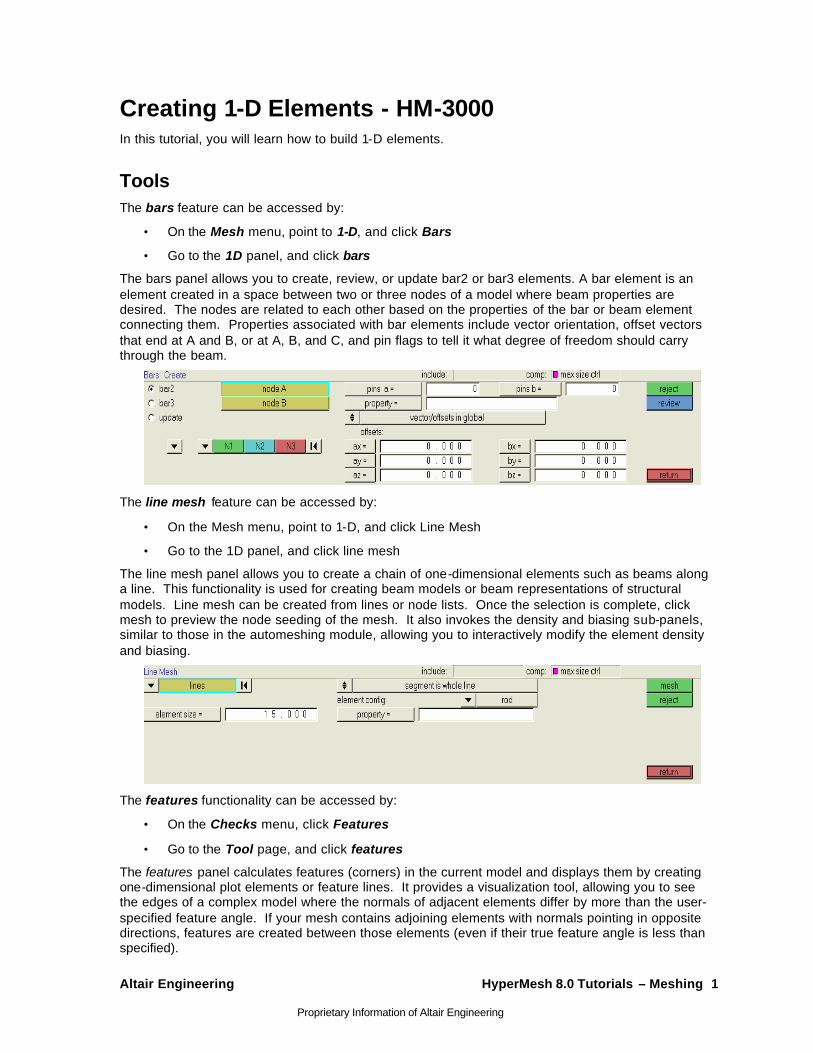
Tools The bars feature can be accessed by:
• On the Mesh menu, point to 1-D, and click Bars
• Go to the 1D panel, and click bars
The bars panel allows you to create, review, or update bar2 or bar3 elements. A bar element is an element created in a space between two or three nodes of a model where beam properties are desired. The nodes are related to each other based on the properties of the bar or beam element connecting them. Properties associated with bar elements include vector orientation, offset vectors that end at A and B, or at A, B, and C, and pin flags to tell it what degree of freedom should carry through the beam.
The line mesh feature can be accessed by:
• On the Mesh menu, point to 1-D, and click Line Mesh
• Go to the 1D panel, and click line mesh
The line mesh panel allows you to create a chain of one-dimensional elements such as beams along a line. This functionality is used for creating beam models or beam representations of structural models. Line mesh can be created from lines or node lists. Once the selection is complete, click mesh to preview the node seeding of the mesh. It also invokes the density and biasing sub-panels, similar to those in the automeshing module, allowing you to interactively modify the element density and biasing.
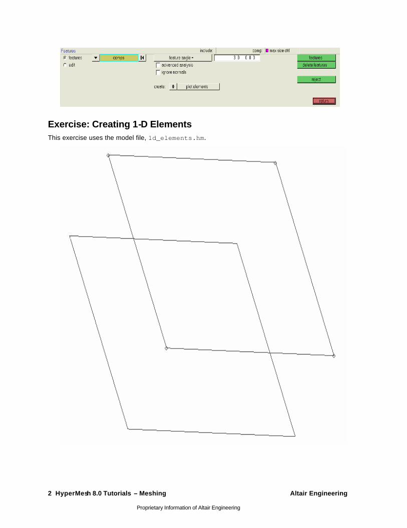
The features functionality can be accessed by:
• On the Checks menu, click Features
• Go to the Tool page, and click features
The features panel calculates features (corners) in the current model and displays them by creating one-dimensional plot elements or feature lines. It provides a visualization tool, allowing you to see the edges of a complex model where the normals of adjacent elements differ by more than the user-specified feature angle. If your mesh contains adjoining elements with normals pointing in opposite directions, features are created between those elements (even if their true feature angle is less than specified).
2 HyperMesh 8.0 Tutorials – Meshing Altair Engineering
Proprietary Information of Altair Engineering
Exercise: Creating 1-D Elements This exercise uses the model file, 1d_elements.hm.

Altair Engineering HyperMesh 8.0 Tutorials – Meshing 3
Proprietary Information of Altair Engineering
Step 1: Create 1-D bar elements.
1. Retrieve the file 1d_elements.hm file, located in the <install_directory>/tutorials/hm/ directory.
2. Ensure that that user profile is the default HyperMesh.
3. Go to the bars panel.
4. Go to the bar2 sub-panel.
5. Click ax = and type the value 0.
6. Click ay = and type the value 0.
7. Click az = and type the value 0.
These are the values for the bar offset.
8. Click property = and select property1.
A property is now assigned to the element.
9. Click pins a = and type the value 0.
10. Click pins b = and type the value 0.
These are the values for the degrees of freedom.
11. Click the switch below update and select components from the pop-up menu.
12. After x comp =, type the value 1.
13. After y comp =, type the value 1.
14. After z comp =, type the value 1.
The local y-axis is now specified.
15. Click node A and select the lower node in the graphics area.
16. Click node B and select the upper node in the graphics area.
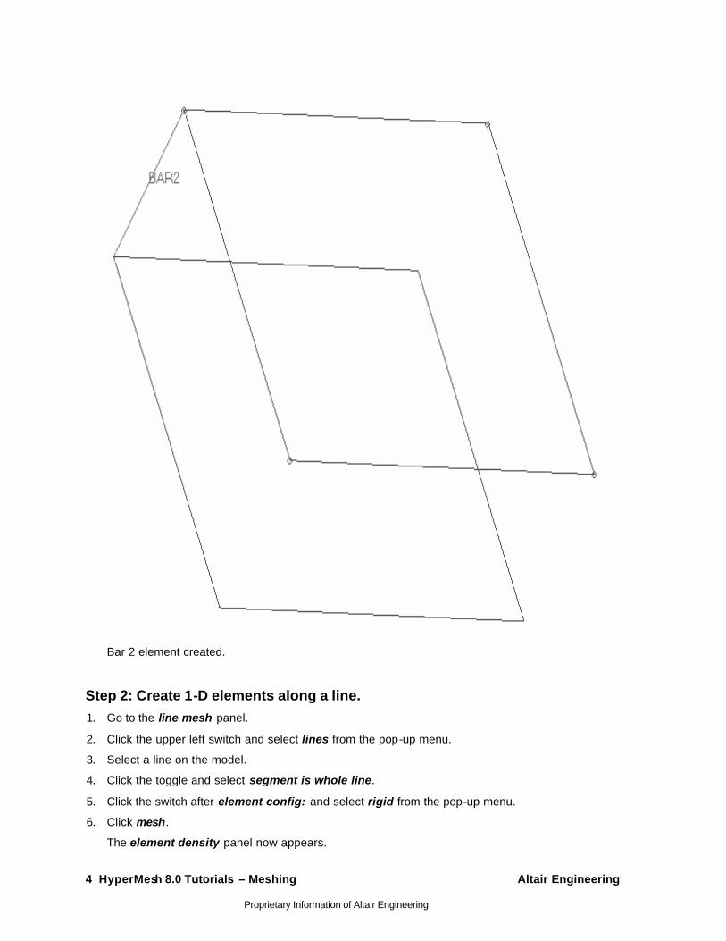
The 2 noded bar element is created.
17. Click return to access the main menu.
4 HyperMesh 8.0 Tutorials – Meshing Altair Engineering
Proprietary Information of Altair Engineering
Bar 2 element created.
Step 2: Create 1-D elements along a line. 1. Go to the line mesh panel.
2. Click the upper left switch and select lines from the pop-up menu.
3. Select a line on the model.
4. Click the toggle and select segment is whole line.
5. Click the switch after element config: and select rigid from the pop-up menu.
6. Click mesh.
The element density panel now appears.
Altair Engineering HyperMesh 8.0 Tutorials – Meshing 5
Proprietary Information of Altair Engineering
7. Click set segment to highlight the box with the blue input cursor.
8. In the elem density = field, type 20.
9. Click set all.
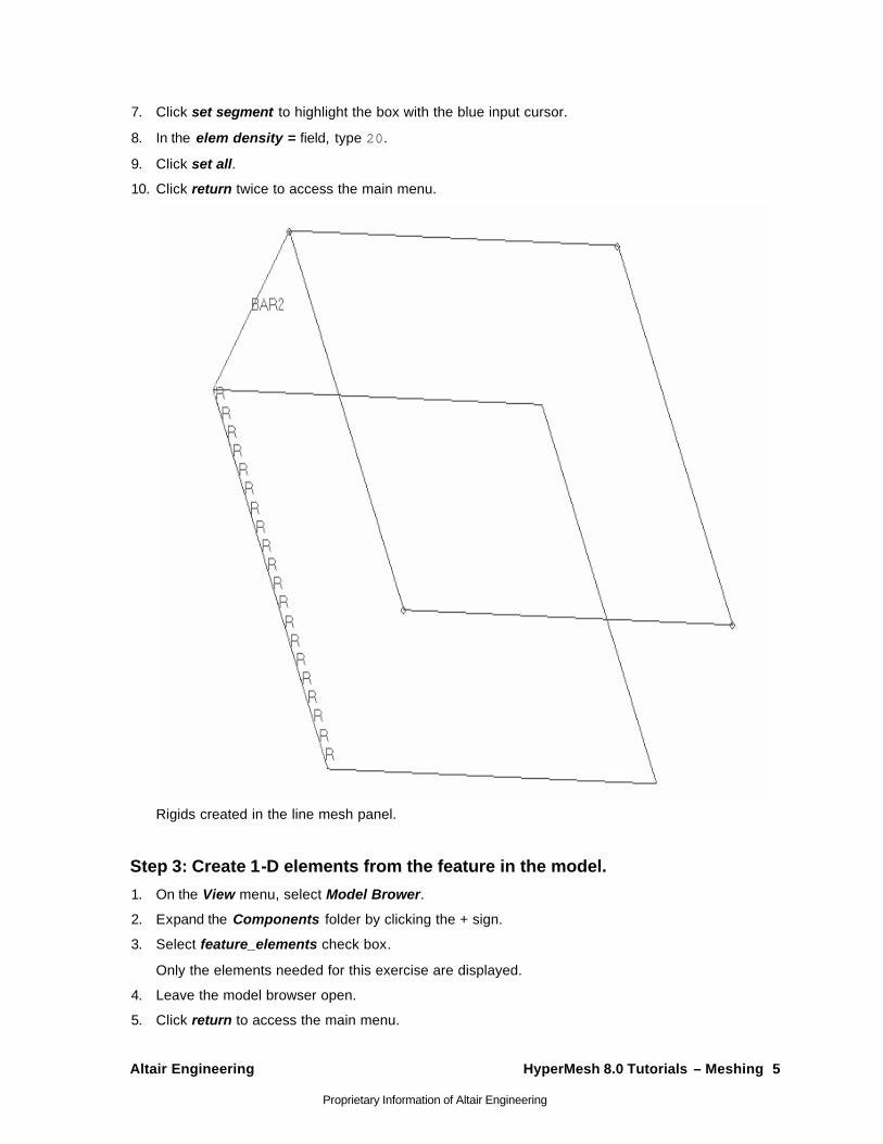
10. Click return twice to access the main menu.
Rigids created in the line mesh panel.
Step 3: Create 1-D elements from the feature in the model.
1. On the View menu, select Model Brower.
2. Expand the Components folder by clicking the + sign.
3. Select feature_elements check box .
Only the elements needed for this exercise are displayed.
4. Leave the model browser open.
5. Click return to access the main menu.

6 HyperMesh 8.0 Tutorials – Meshing Altair Engineering
Proprietary Information of Altair Engineering
6. Go to the features panel.
7. Click Comps.
8. Select the feature_elements check box.
9. Click select.
10. In the feature angle = field, type 30.
11. Select the ignore normals check box.
12. Click the toggle after create: and select plot elements.
Altair Engineering HyperMesh 8.0 Tutorials – Meshing 7
Proprietary Information of Altair Engineering
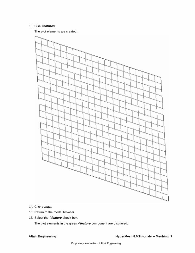
13. Click features.
The plot elements are created.
14. Click return.
15. Return to the model browser.
16. Select the ^feature check box.
The plot elements in the green ^feature component are displayed.
8 HyperMesh 8.0 Tutorials – Meshing Altair Engineering
Proprietary Information of Altair Engineering
Connecting with 1- D - HM- 3010 In this tutorial, you will learn how to:
• Use welds to join elements and components
• Use RBE3s and spring elements to model a rubber grommet
• Use equations to simulate a basic contact constraint between components
• Use rigids and rigidlinks to join elements and components
Rigid elements are displayed as a line between two nodes with the letter R written at the centroid of the element.
Rigid link elements are displayed as lines between the independent node and the dependent node(s) with RL displayed at the independent node of the element.
Rigids can translate to RBE2 in NASTRAN or *MPC in ABAQUS.
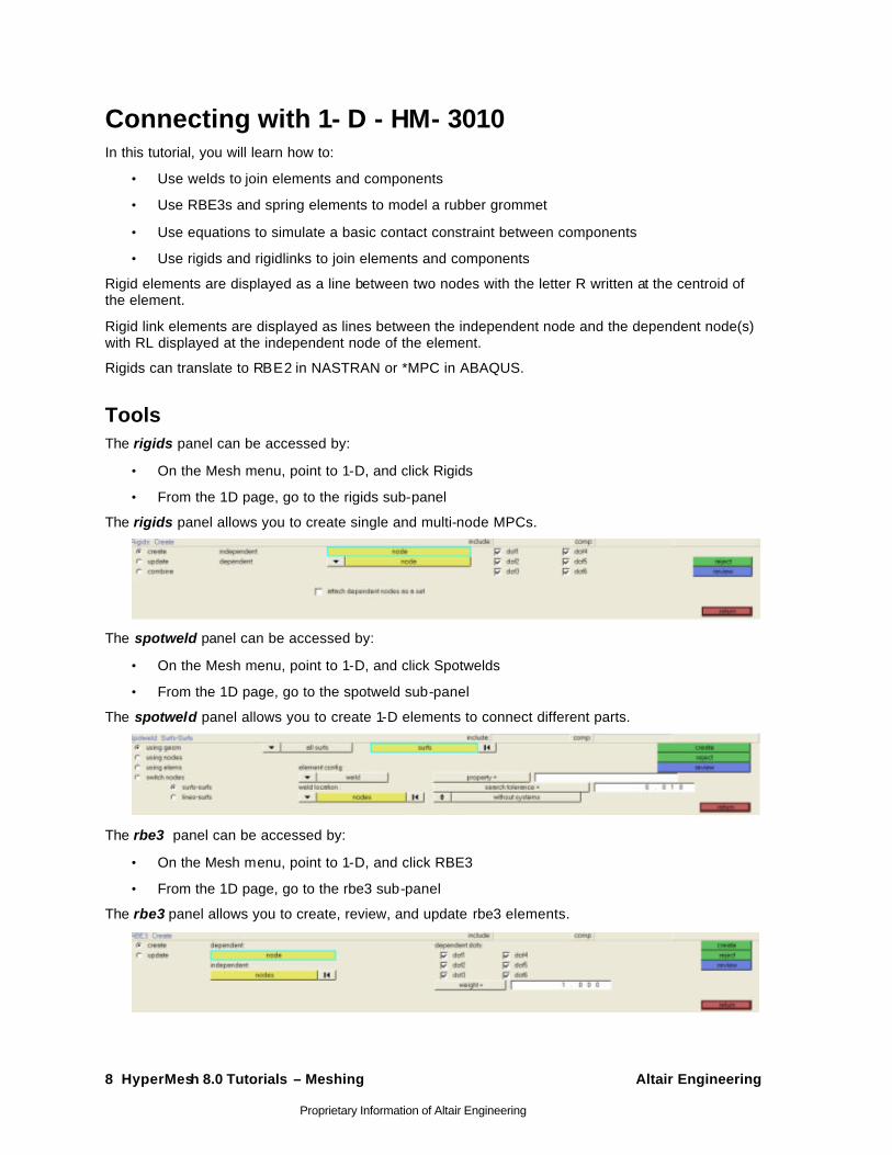
Tools The rigids panel can be accessed by:
• On the Mesh menu, point to 1-D, and click Rigids
• From the 1D page, go to the rigids sub-panel
The rigids panel allows you to create single and multi-node MPCs.
The spotweld panel can be accessed by:
• On the Mesh menu, point to 1-D, and click Spotwelds
• From the 1D page, go to the spotweld sub-panel
The spotweld panel allows you to create 1-D elements to connect different parts.
The rbe3 panel can be accessed by:
• On the Mesh menu, point to 1-D, and click RBE3
• From the 1D page, go to the rbe3 sub-panel
The rbe3 panel allows you to create, review, and update rbe3 elements.
Altair Engineering HyperMesh 8.0 Tutorials – Meshing 9
Proprietary Information of Altair Engineering
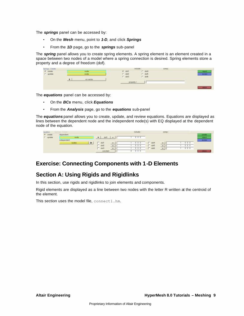
The springs panel can be accessed by:
• On the Mesh menu, point to 1-D, and click Springs
• From the 1D page, go to the springs sub-panel
The spring panel allows you to create spring elements. A spring element is an element created in a space between two nodes of a model where a spring connection is desired. Spring elements store a property and a degree of freedom (dof).
The equations panel can be accessed by:
• On the BCs menu, click Equations
• From the Analysis page, go to the equations sub-panel
The equations panel allows you to create, update, and review equations. Equations are displayed as lines between the dependent node and the independent node(s) with EQ displayed at the dependent node of the equation.
Exercise: Connecting Components with 1-D Elements
Section A: Using Rigids and Rigidlinks In this section, use rigids and rigidlinks to join elements and components.
Rigid elements are displayed as a line between two nodes with the letter R written at the centroid of the element.
This section uses the model file, connect1.hm.
10 HyperMesh 8.0 Tutorials – Meshing Altair Engineering
Proprietary Information of Altair Engineering
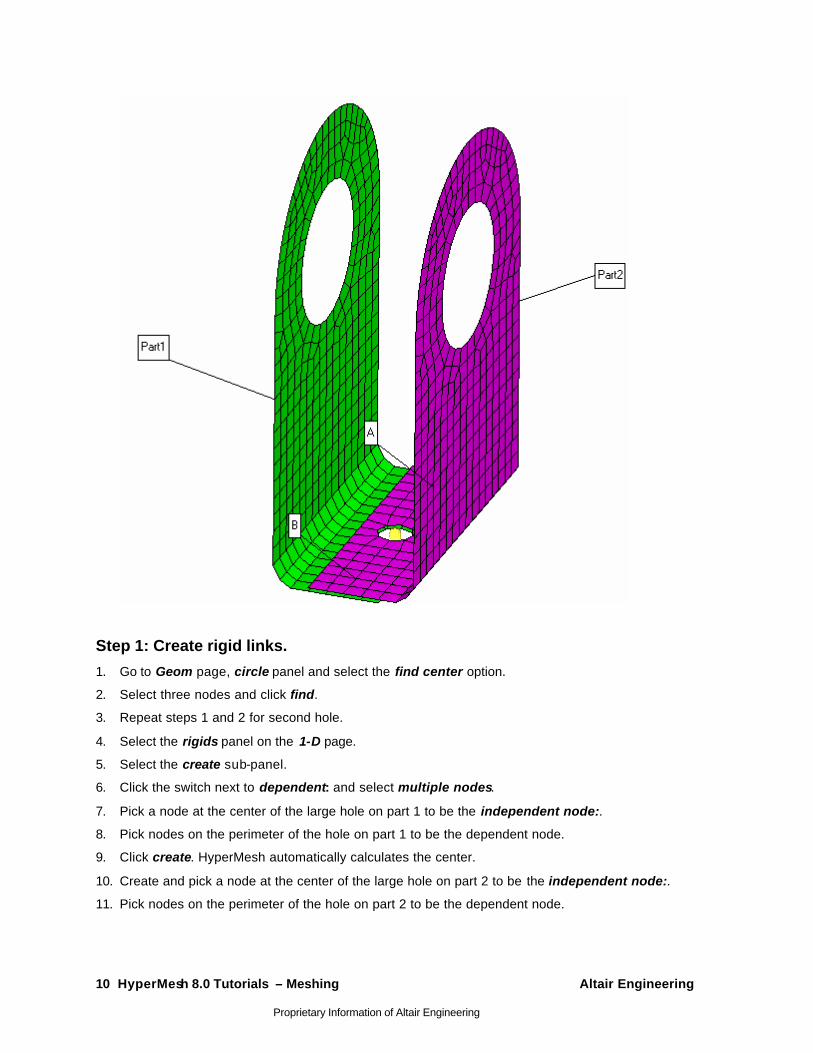
Step 1: Create rigid links.
1. Go to Geom page, circle panel and select the find center option.
2. Select three nodes and click find.
3. Repeat steps 1 and 2 for second hole.
4. Select the rigids panel on the 1-D page.
5. Select the create sub-panel.
6. Click the switch next to dependent: and select multiple nodes.
7. Pick a node at the center of the large hole on part 1 to be the independent node:.
8. Pick nodes on the perimeter of the hole on part 1 to be the dependent node.
9. Click create. HyperMesh automatically calculates the center.
10. Create and pick a node at the center of the large hole on part 2 to be the independent node:.
11. Pick nodes on the perimeter of the hole on part 2 to be the dependent node.
Altair Engineering HyperMesh 8.0 Tutorials – Meshing 11
Proprietary Information of Altair Engineering
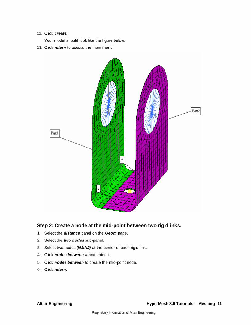
12. Click create.
Your model should look like the figure below.
13. Click return to access the main menu.
Step 2: Create a node at the mid-point between two rigidlinks. 1. Select the distance panel on the Geom page.
2. Select the two nodes sub-panel.
3. Select two nodes (N1/N2) at the center of each rigid link.
4. Click nodes between = and enter 1.
5. Click nodes between to create the mid-point node.
6. Click return.
12 HyperMesh 8.0 Tutorials – Meshing Altair Engineering
Proprietary Information of Altair Engineering
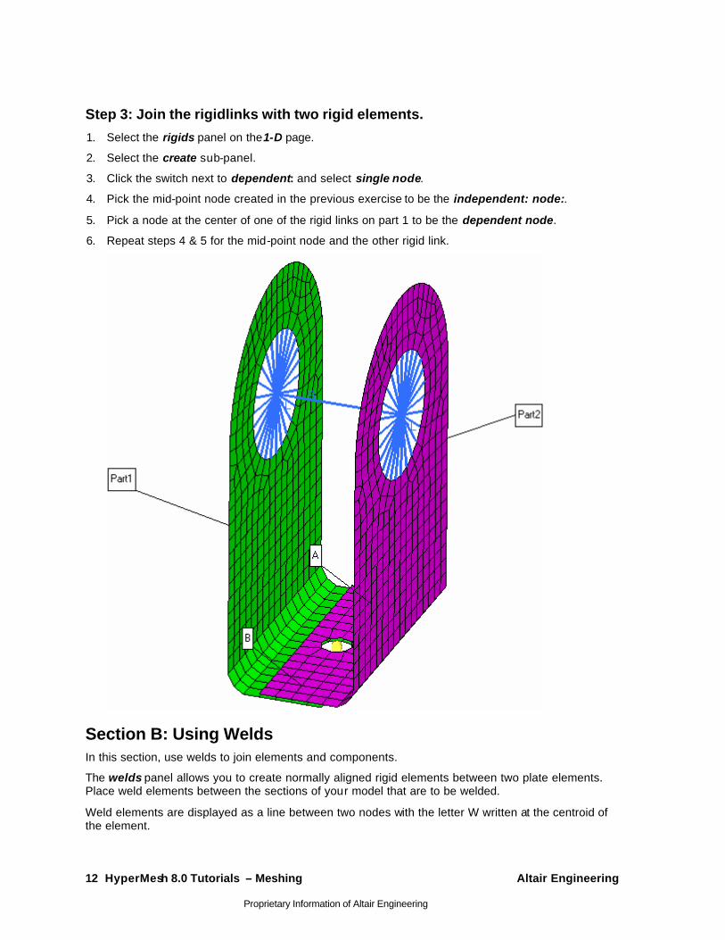
Step 3: Join the rigidlinks with two rigid elements.
1. Select the rigids panel on the1-D page.
2. Select the create sub-panel.
3. Click the switch next to dependent: and select single node.
4. Pick the mid-point node created in the previous exercise to be the independent: node:.
5. Pick a node at the center of one of the rigid links on part 1 to be the dependent node.
6. Repeat steps 4 & 5 for the mid-point node and the other rigid link.
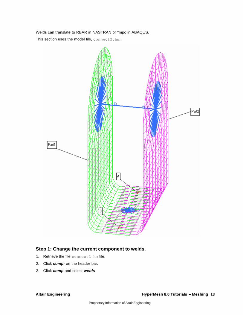
Section B: Using Welds In this section, use welds to join elements and components.
The welds panel allows you to create normally aligned rigid elements between two plate elements. Place weld elements between the sections of your model that are to be welded.
Weld elements are displayed as a line between two nodes with the letter W written at the centroid of the element.
Altair Engineering HyperMesh 8.0 Tutorials – Meshing 13
Proprietary Information of Altair Engineering
Welds can translate to RBAR in NASTRAN or *mpc in ABAQUS.
This section uses the model file, connect2.hm.
Step 1: Change the current component to welds. 1. Retrieve the file connect2.hm file.
2. Click comp: on the header bar.
3. Click comp and select welds.
14 HyperMesh 8.0 Tutorials – Meshing Altair Engineering
Proprietary Information of Altair Engineering
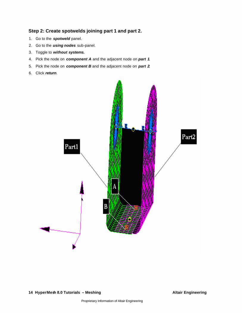
Step 2: Create spotwelds joining part 1 and part 2.
1. Go to the spotweld panel.
2. Go to the using nodes sub-panel.
3. Toggle to without systems.
4. Pick the node on component A and the adjacent node on part 1.
5. Pick the node on component B and the adjacent node on part 2.
6. Click return.

Altair Engineering HyperMesh 8.0 Tutorials – Meshing 15
Proprietary Information of Altair Engineering
Section C: Using RBE3s In this section, use RBE3s to join elements and components.
The rbe3 panel allows you to create, review, and update RBE3 elements. The update sub-panel allows you to edit the connectivity, dofs, and weight for each node of the element.
RBE3 elements are displayed as lines between the dependent node and the independent node(s) with RBE3 displayed at the dependent node of the element.
RBE3’s define the motion at a reference grid point -the dependent node- as the weighted average of the motions at a set of other grid points -the independent nodes. RBE3 is used in NASTRAN.
Step 1: Change the current component to rigids. 1. Retrieve the file, connect3.hm file.
2. Select the global panel on the permanent menu.
3. Click component = and select rigids.
4. Click return.
Step 2: Create RBE3s at the small holes. 1. Select the rbe3 panel on the 1-D page.
2. Select the create sub-panel.
3. Pick a node at the center of the small hole on component A to be the dependent node.
4. Pick nodes on the perimeter of component A to be the independent nodes.
5. Click create.
6. Pick a node at the center of the small hole on component B to be the dependent node.
7. Pick nodes on the perimeter of component B to be the independent nodes.
8. Click create.
9. Click return.
16 HyperMesh 8.0 Tutorials – Meshing Altair Engineering
Proprietary Information of Altair Engineering
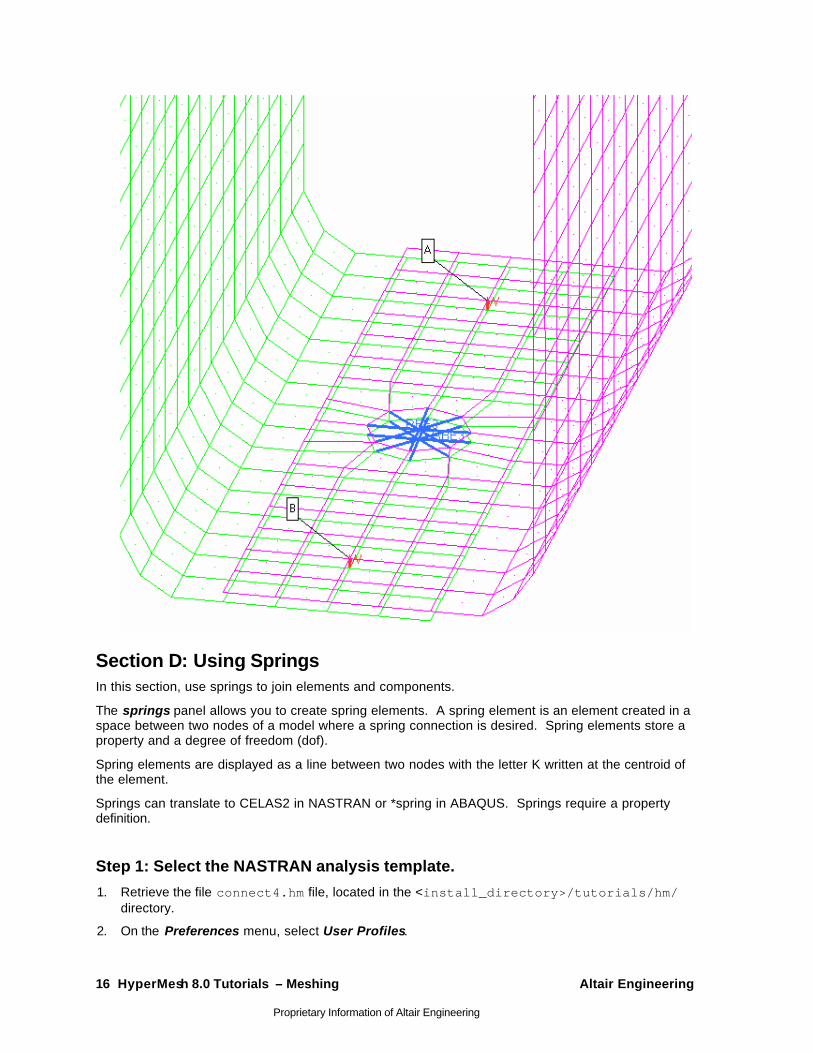
Section D: Using Springs In this section, use springs to join elements and components.
The springs panel allows you to create spring elements. A spring element is an element created in a space between two nodes of a model where a spring connection is desired. Spring elements store a property and a degree of freedom (dof).
Spring elements are displayed as a line between two nodes with the letter K written at the centroid of the element.
Springs can translate to CELAS2 in NASTRAN or *spring in ABAQUS. Springs require a property definition.
Step 1: Select the NASTRAN analysis template.
1. Retrieve the file connect4.hm file, located in the <install_directory>/tutorials/hm/ directory.
2. On the Preferences menu, select User Profiles.

Altair Engineering HyperMesh 8.0 Tutorials – Meshing 17
Proprietary Information of Altair Engineering
3. Select Nastran.
Step 2: Change the current component to springs.
• Click comp on the toolbar and select springs.
Step 3: Create a spring property definition.
1. On the toolbar, click the collectors icon .
2. Select the create sub-panel.
3. Click the switch after collector type: and select properties.
4. Click name = and enter k1.
5. Click card image = and select PELAS.
6. Click create/edit.
HyperMesh goes to the card image sub-panel. This allows you to enter the NASTRAN card data.
7. Click the data entry field under K1 and enter 1.0 as the spring constant.
8. Click return twice to access to the main menu.
Step 4: Create a spring element joining the RBE3s.
1. Select the springs panel on the 1-D page.
2. Click property = and select k1.
3. Select dof2.
4. Click the toggle and select no vector.
The other options are off by default.
5. Pick a node at the center of one of the RBE3 elements.
6. Pick a node at the center of the other RBE3 element.
The spring element is created and represented by a "CELAS1".
7. Click return.
18 HyperMesh 8.0 Tutorials – Meshing Altair Engineering
Proprietary Information of Altair Engineering
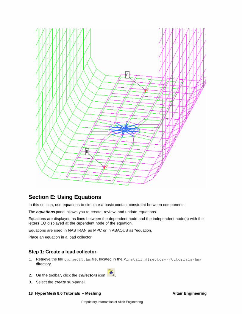
Section E: Using Equations In this section, use equations to simulate a basic contact constraint between components.
The equations panel allows you to create, review, and update equations.
Equations are displayed as lines between the dependent node and the independent node(s) with the letters EQ displayed at the dependent node of the equation.
Equations are used in NASTRAN as MPC or in ABAQUS as *equation.
Place an equation in a load collector.
Step 1: Create a load collector. 1. Retrieve the file connect5.hm file, located in the <install_directory>/tutorials/hm/
directory.
2. On the toolbar, click the collectors icon .
3. Select the create sub-panel.
Altair Engineering HyperMesh 8.0 Tutorials – Meshing 19
Proprietary Information of Altair Engineering
4. Click the switch after collector type: and select load collectors.
5. Click name = and enter the name equations.
6. Click color and select any color.
7. Click create.
The collector was created.
8. Click return to access the main menu.
Step 2: Set up the constraints equations.
1. Select the equations panel on the Analysis page.
2. Select the create sub-panel.
3. Click the switch and select dof2 as the dependent node degree of freedom.
4. Activate dof2 as the independent node degree of freedom. Deactivate any other degree of freedom options selected.
5. Ensure w has a value of 1.0.
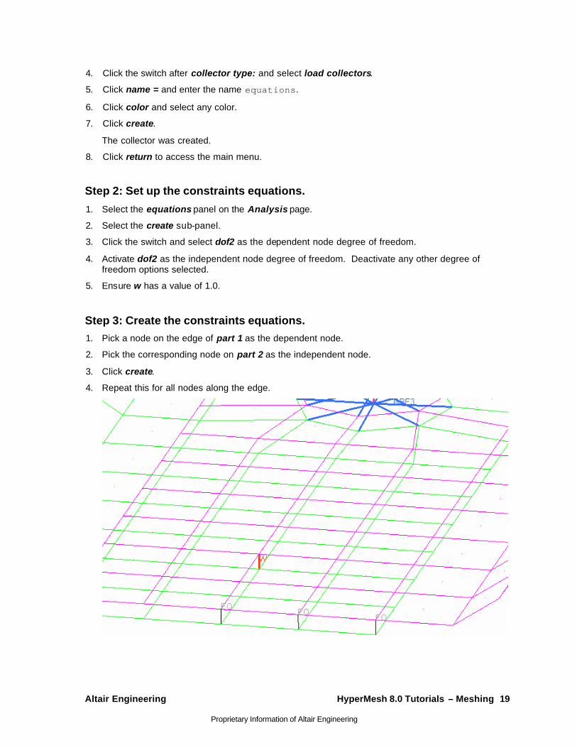
Step 3: Create the constraints equations. 1. Pick a node on the edge of part 1 as the dependent node.
2. Pick the corresponding node on part 2 as the independent node.
3. Click create.
4. Repeat this for all nodes along the edge.

20 HyperMesh 8.0 Tutorials – Meshing Altair Engineering
Proprietary Information of Altair Engineering
AutoMeshing - HM-3100 In this tutorial, you will learn how to:
• Mesh all the surfaces at once specifying different element sizes and element types.
• Practice changing the element density along surface edges.
• Practice checking element quality and changing the mesh pattern by changing the mesh algorithm.
• Preview the mesh on all the unmeshed surfaces.
• Practice changing the element type and node spacing (biasing) along surface edges.
• Re-mesh surfaces.
The optimal starting point for creating a shell mesh for a part is to have geometry surfaces defining the part. The most efficient method for creating a mesh representing the part includes using the automesh panel and creating a mesh directly on the part’s surfaces.
Overview It is highly recommended before you begin the exercise, you review the general overview for this tutorial.
Tool The automesh panel can be accessed by one of the following ways:
• On the Mesh menu, click AutoMesh
• On the 2D page, click automesh
The automesh panel is a key meshing tool in HyperMesh. Its meshing module allows you to specify and control element size, density, type, and node spacing, and perform quality checks before accepting the final mesh.
A part can be meshed all at once or in portions. To mesh a part all at once, it may be advantageous to first perform geometry cleanup of the surfaces, which can be done in HyperMesh.
Altair Engineering HyperMesh 8.0 Tutorials – Meshing 21
Proprietary Information of Altair Engineering
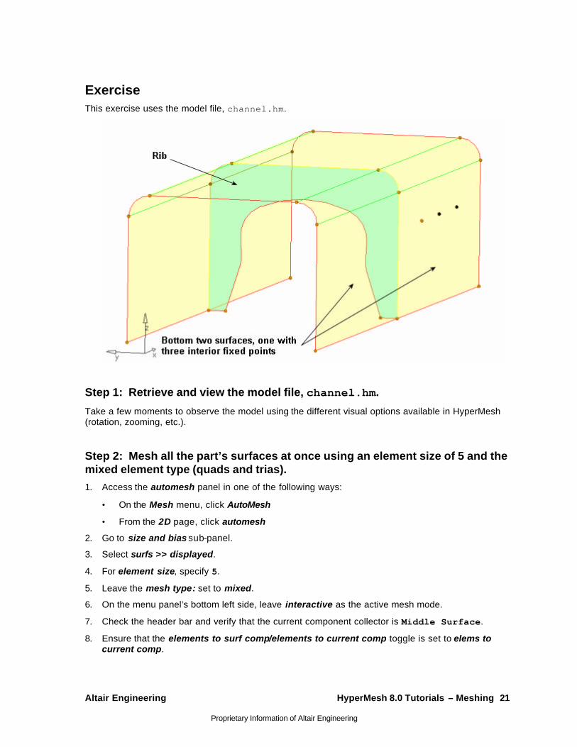
Exercise This exercise uses the model file, channel.hm.
Step 1: Retrieve and view the model file, channel.hm.
Take a few moments to observe the model using the different visual options available in HyperMesh (rotation, zooming, etc.).
Step 2: Mesh all the part’s surfaces at once using an element size of 5 and the mixed element type (quads and trias). 1. Access the automesh panel in one of the following ways:
• On the Mesh menu, click AutoMesh
• From the 2D page, click automesh
2. Go to size and bias sub-panel.
3. Select surfs >> displayed.
4. For element size, specify 5.
5. Leave the mesh type: set to mixed.
6. On the menu panel’s bottom left side, leave interactive as the active mesh mode.
7. Check the header bar and verify that the current component collector is Middle Surface.
8. Ensure that the elements to surf comp/elements to current comp toggle is set to elems to current comp.

22 HyperMesh 8.0 Tutorials – Meshing Altair Engineering
Proprietary Information of Altair Engineering
9. Click mesh to enter the meshing module.
Notice that you are in the density sub-panel of the meshing module. There is node seeding and a number on each surface edge. The number is the number of elements that were created along the edge.
10. Click return to accept the mesh as the final mesh.
At this point, you could be done using the automesh panel to mesh the part. The mesh quality is very good. However, you will remain in the meshing module to perform the next steps, which demonstrate how to use various sub-panels to interactively control the creation of the mes h.
Step 3: Delete the mesh.
1. Press the F2 key to access the delete panel.
2. Switch the entity selector to elems.
3. Select elems >> all.
4. Click delete entity.
5. Return to the automesh panel.
Step 4: Mesh the surface having three fixed points interior to its surface. You should still be in the automesh panel, size and bias sub-panel.
1. Leave all options in the menu panel as they are.
2. Click mesh to enter the meshing module.
3. Preview the mesh generated.
Step 5: Fill only the surface being meshed to the graphics area. 1. File the surface to the graphics area in one of the following ways.
• On the density sub-panel, click f.
• Click local view to fill.
Step 6: From the graphics area, specify a new element density along surface edges.
1. From the density sub-panel, click the selector, adjust : edge to make it active.
2. From the graphics area, left -click on an edge’s element density number to increase it by one.
3. Right -click on an edge’s number to decrease it by one.
4. Click and hold the mouse pointer on an edge’s number and drag the mouse up or down to increase or decrease the number.
5. Click mesh to update the preview mesh based on the change.
Rather than click mesh, you can middle mouse click in the graphics area to update the preview mesh.

Altair Engineering HyperMesh 8.0 Tutorials – Meshing 23
Proprietary Information of Altair Engineering
Step 7: From the menu panel, specify a new element density along surface edges.
1. From the density sub-panel, for element density specify 10.
2. Activate the selector set : edge.
3. Click on an edge’s number to change its value to 10.
4. Update the mesh to preview the change.
5. Change all edge densities to 10 by clicking set all to.
6. Click mesh to preview the change.
Step 8: From the menu panel, specify a new element size to adjust element densities along surface edges.
You should still be in the density sub-panel.
1. For elem size, specify 7.
2. Make active the selector calculate: edge.
3. Click on an edge’s number to calculate it based on an element size of 7.
The new number is rounded up.
4. Click mesh to preview the change.
5. Click recalc all to base all edge densities on an element size of 7.
6. Click mesh to preview the change.
Step 9: Change all edge element densities to reflect the initial element size of 5.
1. For element size, specify 5.
2. Click recalc all.
3. Click mesh to preview the change.
4. Return to accept the mesh and go back to the size and bias sub-panel.
Step 10: Preview a mesh of the channel’s rib. You should still be in the automesh panel, size and bias sub-panel.
1. With the surfs selector active, select the rib surface.
2. Leave all options in the menu panel set they are.
3. Click mesh to enter the meshing module.
4. Preview the mesh generated.
5. Click local view and select the rear view to display the rib’s surface in this position, filled to the graphics area.
24 HyperMesh 8.0 Tutorials – Meshing Altair Engineering
Proprietary Information of Altair Engineering
Step 11: Check the quality of the rib’s preview mesh. 1. Go to the checks sub-panel.
2. Click aspect to identify all elements having an aspect ratio greater than 5.
3. Notice that no elements fail this check. In the header bar, the highest aspect ratio value reported is 1.72.
4. For jacobian specify 0.8.
5. Click jacobian to identify all elements having a jacobian less than 0.8.
6. Notice that several elements fail this check and are outlined red. The header bar reports the smallest jacobian value to be 0.71.
7. Change jacobian back to 0.7.
8. Verify that no elements have a jacobian less than 0.7. (Click jacobian.).
9. Check for quad elements having a min angle less than 45.
10. Smallest angle is _____.
11. Check for quad elements having a max angle greater than 135.
12. Largest angle is _____.
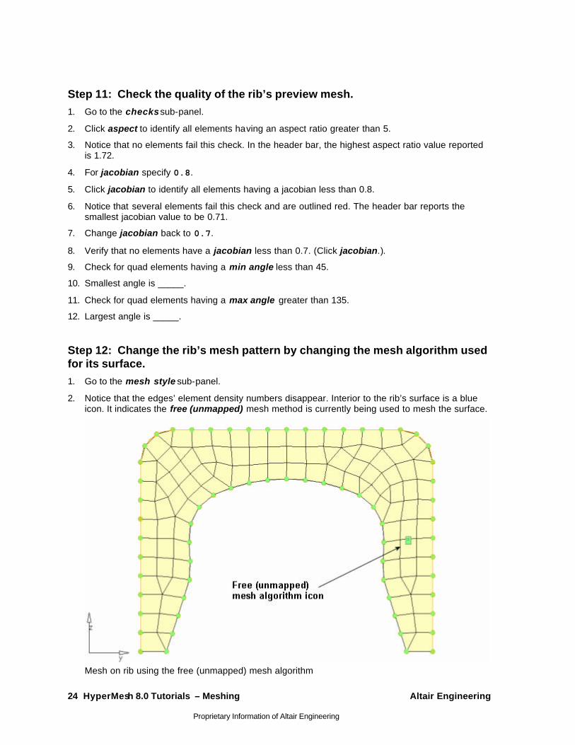
Step 12: Change the rib’s mesh pattern by changing the mesh algorithm used for its surface. 1. Go to the mesh style sub-panel.
2. Notice that the edges’ element density numbers disappear. Interior to the rib’s surface is a blue icon. It indicates the free (unmapped) mesh method is currently being used to mesh the surface.
Mesh on rib using the free (unmapped) mesh algorithm
Altair Engineering HyperMesh 8.0 Tutorials – Meshing 25
Proprietary Information of Altair Engineering
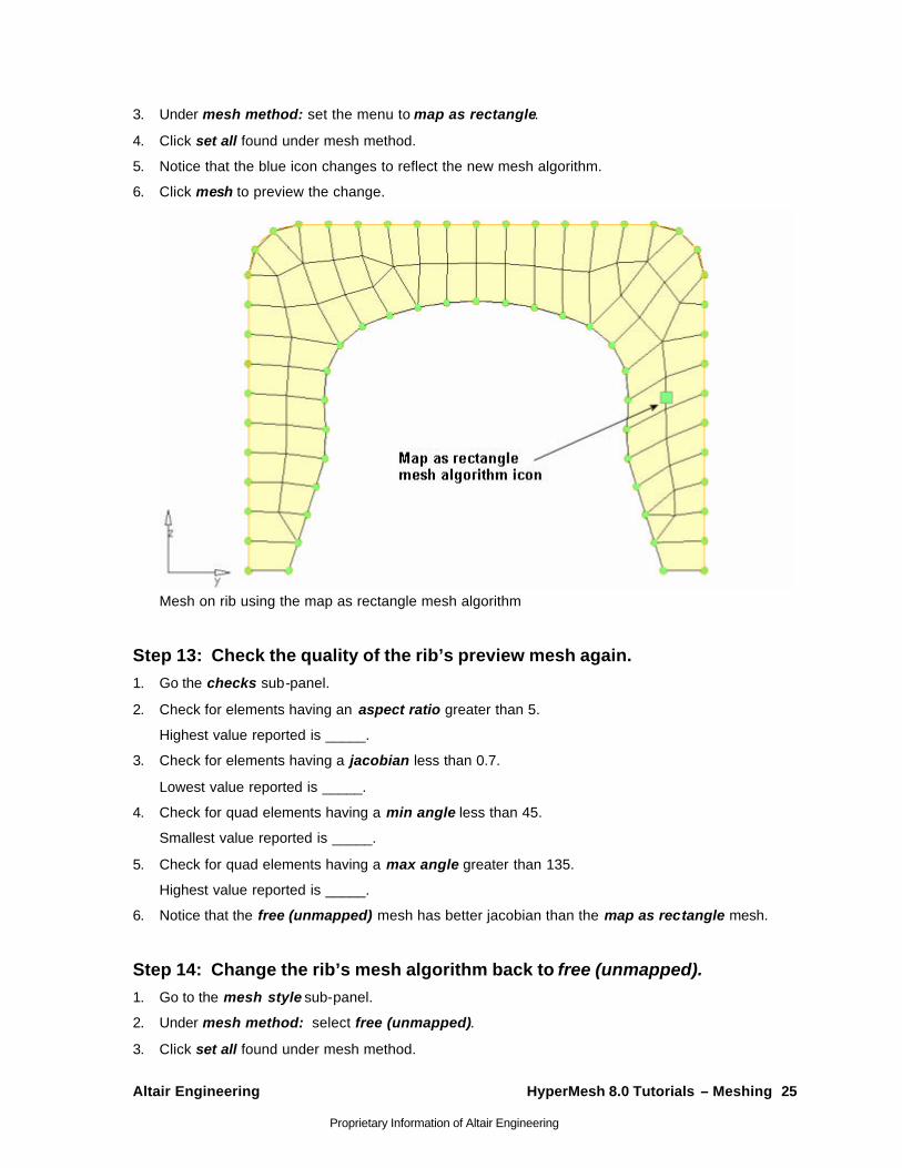
3. Under mesh method: set the menu to map as rectangle.
4. Click set all found under mesh method.
5. Notice that the blue icon changes to reflect the new mesh algorithm.
6. Click mesh to preview the change.
Mesh on rib using the map as rectangle mesh algorithm
Step 13: Check the quality of the rib’s preview mesh again. 1. Go the checks sub-panel.
2. Check for elements having an aspect ratio greater than 5.
Highest value reported is _____.
3. Check for elements having a jacobian less than 0.7.
Lowest value reported is _____.
4. Check for quad elements having a min angle less than 45.
Smallest value reported is _____.
5. Check for quad elements having a max angle greater than 135.
Highest value reported is _____.
6. Notice that the free (unmapped) mesh has better jacobian than the map as rectangle mesh.
Step 14: Change the rib’s mesh algorithm back to free (unmapped). 1. Go to the mesh style sub-panel.
2. Under mesh method: select free (unmapped).
3. Click set all found under mesh method.
26 HyperMesh 8.0 Tutorials – Meshing Altair Engineering
Proprietary Information of Altair Engineering
4. Click mesh to preview the change.
5. Click return to accept the mesh as final and go back to the automesh panel.
Step 15: Preview a mesh of all displayed, unmeshed surfaces. You should still be in the automesh panel, size and bias sub-panel.
1. Press V on the keyboard, and select iso 1.
2. Accept all the default values.
3. On the menu panel’s bottom right side, click failed surfs.
4. Identify all displayed surfaces that failed to mesh.
The header bar displays the following message: "There are no surfaces with meshing errors". This is correct; all surfaces you selected to mesh so far have a mesh on them.
5. Click unmeshed surfs to identify and select all displayed unmeshed surfaces.
6. Click mesh to enter the meshing module.
7. Preview the mesh generated.
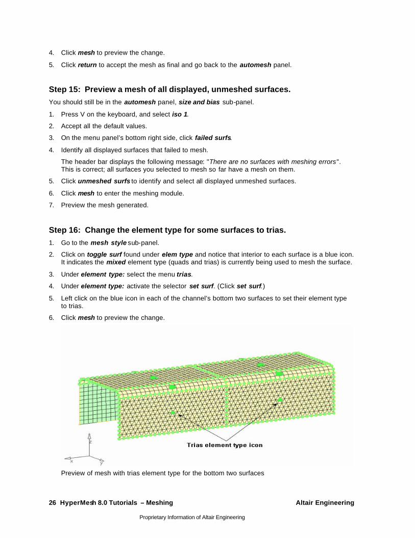
Step 16: Change the element type for some surfaces to trias. 1. Go to the mesh style sub-panel.
2. Click on toggle surf found under elem type and notice that interior to each surface is a blue icon. It indicates the mixed element type (quads and trias) is currently being used to mesh the surface.
3. Under element type: select the menu trias.
4. Under element type: activate the selector set surf. (Click set surf.)
5. Left click on the blue icon in each of the channel’s bottom two surfaces to set their element type to trias.
6. Click mesh to preview the change.
Preview of mesh with trias element type for the bottom two surfaces
Altair Engineering HyperMesh 8.0 Tutorials – Meshing 27
Proprietary Information of Altair Engineering
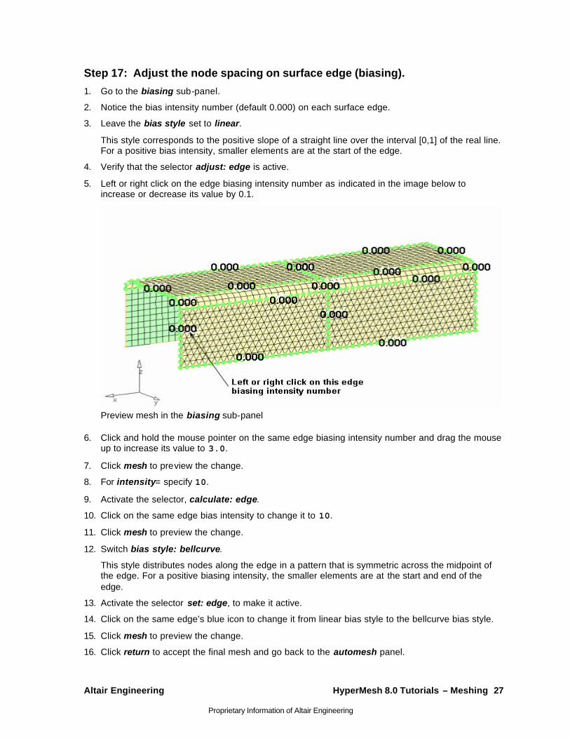
Step 17: Adjust the node spacing on surface edge (biasing).
1. Go to the biasing sub-panel.
2. Notice the bias intensity number (default 0.000) on each surface edge.
3. Leave the bias style set to linear.
This style corresponds to the positive slope of a straight line over the interval [0,1] of the real line. For a positive bias intensity, smaller elements are at the start of the edge.
4. Verify that the selector adjust: edge is active.
5. Left or right click on the edge biasing intensity number as indicated in the image below to increase or decrease its value by 0.1.
Preview mesh in the biasing sub-panel
6. Click and hold the mouse pointer on the same edge biasing intensity number and drag the mouse up to increase its value to 3.0.
7. Click mesh to preview the change.
8. For intensity= specify 10.
9. Activate the selector, calculate: edge.
10. Click on the same edge bias intensity to change it to 10.
11. Click mesh to preview the change.
12. Switch bias style: bellcurve.
This style distributes nodes along the edge in a pattern that is symmetric across the midpoint of the edge. For a positive biasing intensity, the smaller elements are at the start and end of the edge.
13. Activate the selector set: edge, to make it active.
14. Click on the same edge’s blue icon to change it from linear bias style to the bellcurve bias style.
15. Click mesh to preview the change.
16. Click return to accept the final mesh and go back to the automesh panel.
28 HyperMesh 8.0 Tutorials – Meshing Altair Engineering
Proprietary Information of Altair Engineering
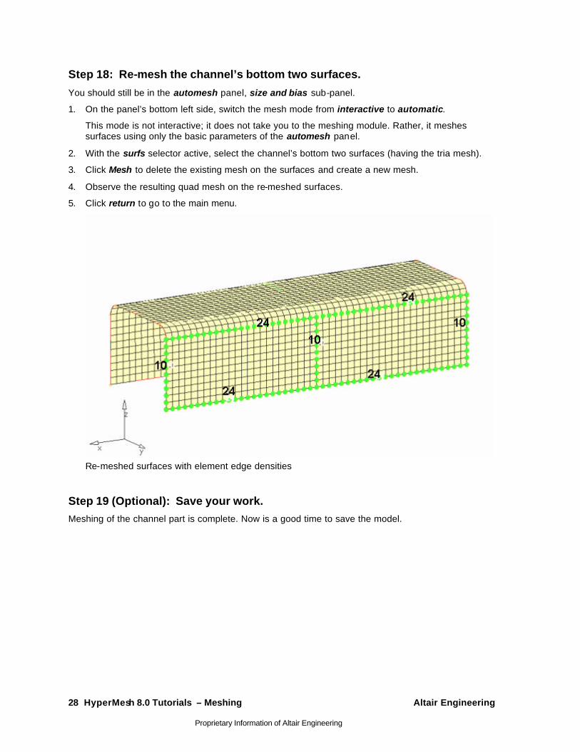
Step 18: Re-mesh the channel’s bottom two surfaces.
You should still be in the automesh panel, size and bias sub-panel.
1. On the panel’s bottom left side, switch the mesh mode from interactive to automatic.
This mode is not interactive; it does not take you to the meshing module. Rather, it meshes surfaces using only the basic parameters of the automesh panel.
2. With the surfs selector active, select the channel’s bottom two surfaces (having the tria mesh).
3. Click Mesh to delete the existing mesh on the surfaces and create a new mesh.
4. Observe the resulting quad mesh on the re-meshed surfaces.
5. Click return to go to the main menu.
Re-meshed surfaces with element edge densities
Step 19 (Optional): Save your work. Meshing of the channel part is complete. Now is a good time to save the model.
Altair Engineering HyperMesh 8.0 Tutorials – Meshing 29
Proprietary Information of Altair Engineering
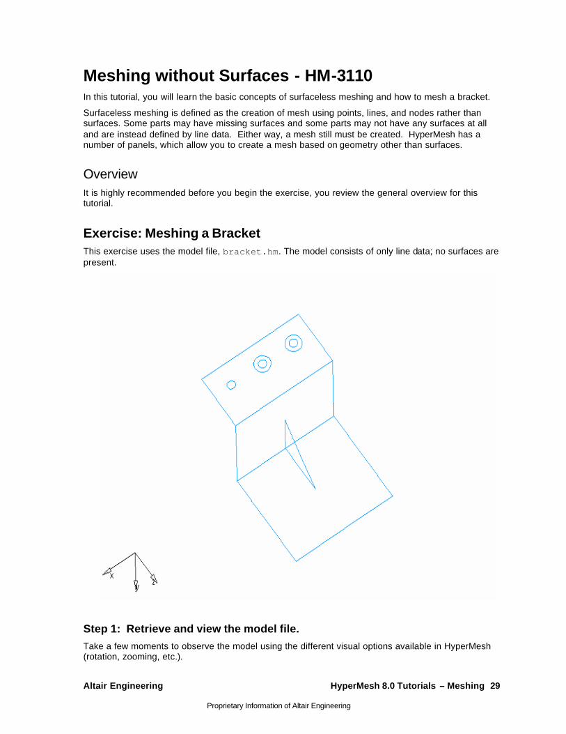
Meshing without Surfaces - HM-3110 In this tutorial, you will learn the basic concepts of surfaceless meshing and how to mesh a bracket.
Surfaceless meshing is defined as the creation of mesh using points, lines, and nodes rather than surfaces. Some parts may have missing surfaces and some parts may not have any surfaces at all and are instead defined by line data. Either way, a mesh still must be created. HyperMesh has a number of panels, which allow you to create a mesh based on geometry other than surfaces.
Overview It is highly recommended before you begin the exercise, you review the general overview for this tutorial.
Exercise: Meshing a Bracket This exercise uses the model file, bracket.hm. The model consists of only line data; no surfaces are present.
Step 1: Retrieve and view the model file. Take a few moments to observe the model using the different visual options available in HyperMesh (rotation, zooming, etc.).

30 HyperMesh 8.0 Tutorials – Meshing Altair Engineering
Proprietary Information of Altair Engineering
Step 2: Create a concentric circle around a hole on the top face using the scale panel.
There are three circles on the upper region of the bracket representing three holes in the bracket. Two of the holes have concentric circles around them. This configuration allows you to create a radial mesh pattern around the holes. The following steps will show how a concentric circle can be created around the third hole.
1. To go to the scale panel, do one of the following:
• On the Tools menu, click on Scale
• On the Tool page, go to scale
2. Click uniform and enter 2.0 for the scale factor.
3. Press F4 to go to the distance panel.
4. Go to the three nodes sub-panel.
5. Verify that the node selector N1 is active.
6. Move the mouse to the graphics area. Keeping the left mouse button pressed, drag the mouse pointer over the circle representing the hole. When the mouse pointer changes to a square and the circle is highlighted, release the mouse button. The circle remains highlighted. Left click on the highlighted circle to create a node for N1. Click twice more, at different locations on the line, to create nodes N2 and N3.
7. Click circle center.
A node is created at the circle’s center. This node will be selected as the origin node when the circle is duplicated and scaled.
8. Click return to go back to the scale panel.
9. Switch the entity type to lines.
10. From the graphics area, select the circle’s line.
11. Click lines, then duplicate , then original comp.
12. Click the origin: node selector to make it active.
13. Select the temporary node you created at the circle’s center.
14. Click scale +.
A new circle is created, which is concentric with the original.
15. Click return.
Step 3: Create a radial mesh between each of the concentric circles using the spline panel.
1. To go to the spline panel, do one of the following:
• On the Mesh menu, point to 2-D and click Spline
• On the 2D page, go to spline.
2. With the entity type set to lines, select all six circular lines.
3. Switch mesh, keep surf to mesh, dele surf.
This option creates surfaces based on the selected entities, uses the surfaces to create a mesh, and then deletes the surfaces.
Altair Engineering HyperMesh 8.0 Tutorials – Meshing 31
Proprietary Information of Altair Engineering
4. Click create.
5. Answer Yes to the pop-up question: "Lines appear planar, project to plane? (y/n)".
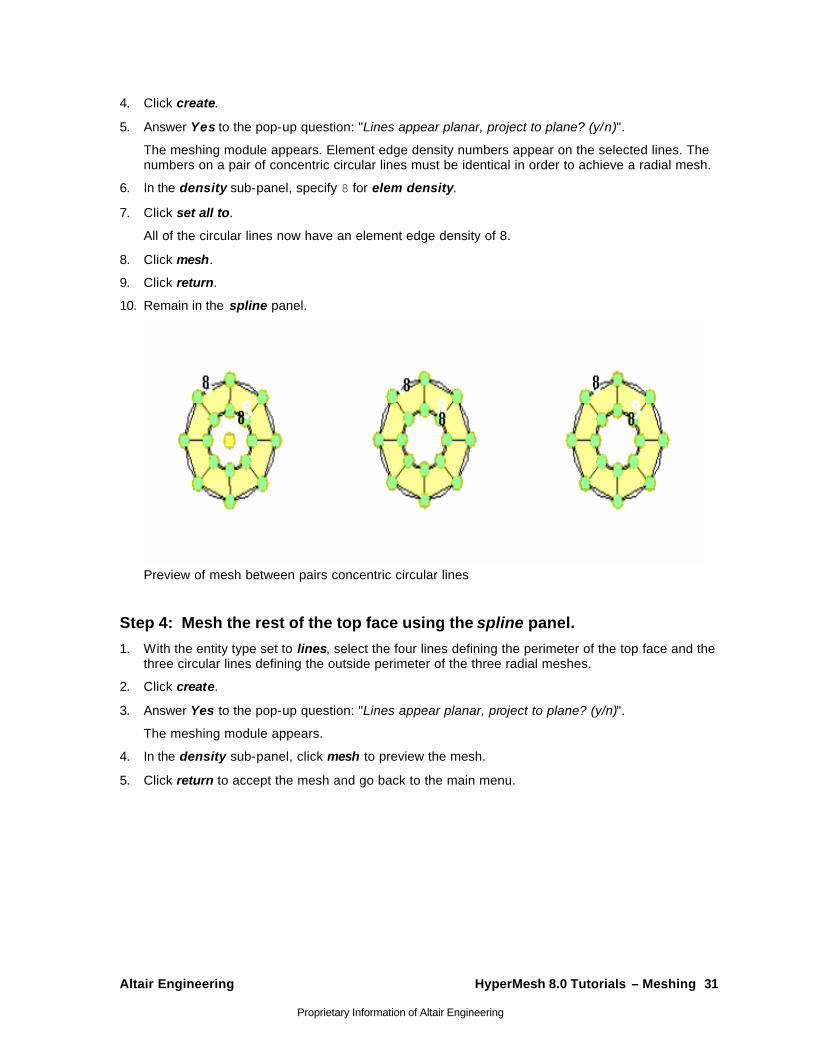
The meshing module appears. Element edge density numbers appear on the selected lines. The numbers on a pair of concentric circular lines must be identical in order to achieve a radial mesh.
6. In the density sub-panel, specify 8 for elem density.
7. Click set all to.
All of the circular lines now have an element edge density of 8.
8. Click mesh.
9. Click return.
10. Remain in the spline panel.
Preview of mesh between pairs concentric circular lines
Step 4: Mesh the rest of the top face using the spline panel.
1. With the entity type set to lines, select the four lines defining the perimeter of the top face and the three circular lines defining the outside perimeter of the three radial meshes.
2. Click create.
3. Answer Yes to the pop-up question: "Lines appear planar, project to plane? (y/n)".
The meshing module appears.
4. In the density sub-panel, click mesh to preview the mesh.
5. Click return to accept the mesh and go back to the main menu.
32 HyperMesh 8.0 Tutorials – Meshing Altair Engineering
Proprietary Information of Altair Engineering
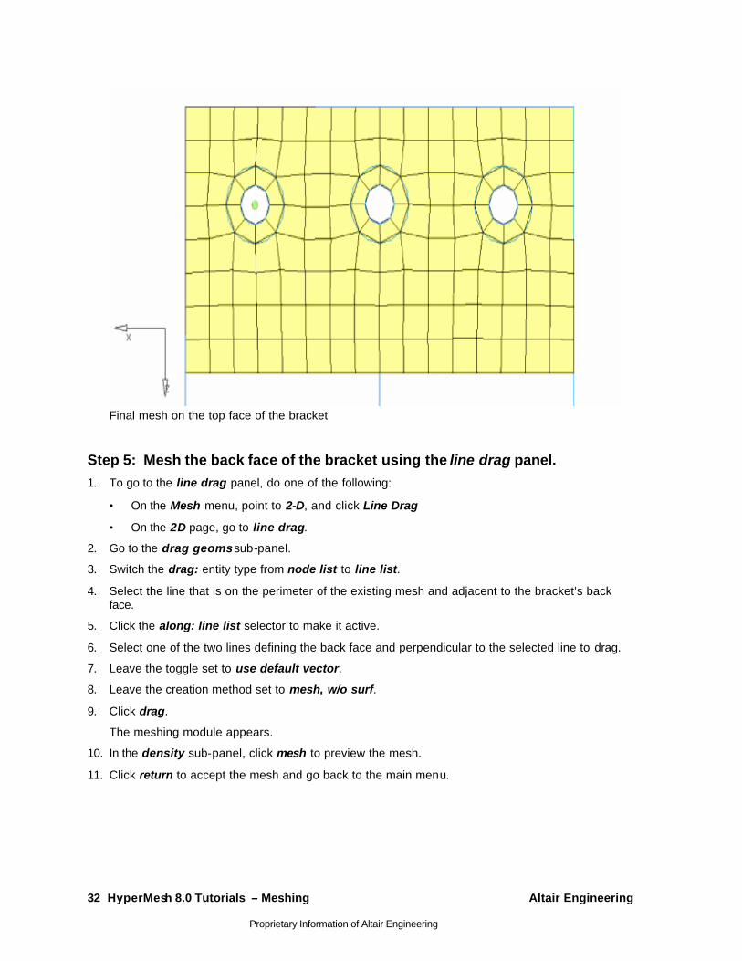
Final mesh on the top face of the bracket
Step 5: Mesh the back face of the bracket using the line drag panel. 1. To go to the line drag panel, do one of the following:
• On the Mesh menu, point to 2-D, and click Line Drag
• On the 2D page, go to line drag.
2. Go to the drag geoms sub-panel.
3. Switch the drag: entity type from node list to line list.
4. Select the line that is on the perimeter of the existing mesh and adjacent to the bracket’s back face.
5. Click the along: line list selector to make it active.
6. Select one of the two lines defining the back face and perpendicular to the selected line to drag.
7. Leave the toggle set to use default vector.
8. Leave the creation method set to mesh, w/o surf.
9. Click drag.
The meshing module appears.
10. In the density sub-panel, click mesh to preview the mesh.
11. Click return to accept the mesh and go back to the main menu.
Altair Engineering HyperMesh 8.0 Tutorials – Meshing 33
Proprietary Information of Altair Engineering
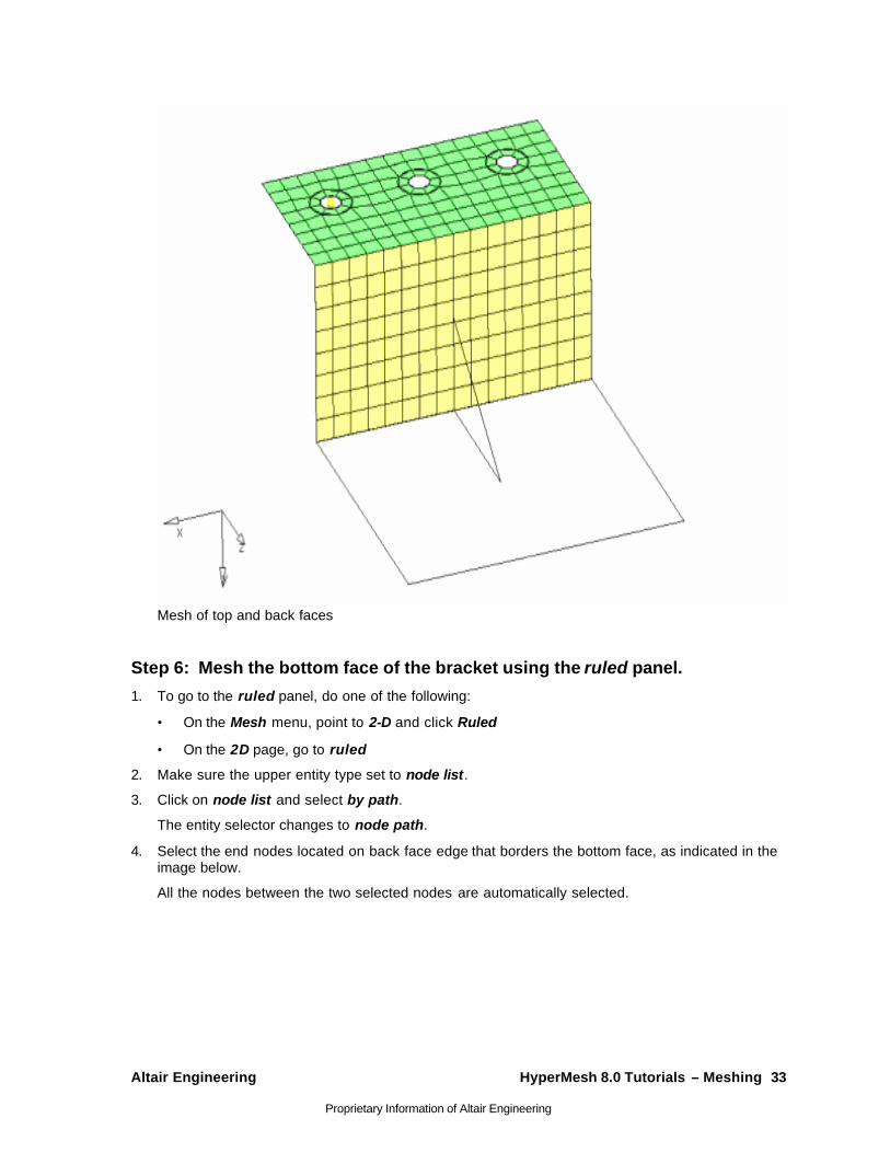
Mesh of top and back faces
Step 6: Mesh the bottom face of the bracket using the ruled panel.
1. To go to the ruled panel, do one of the following:
• On the Mesh menu, point to 2-D and click Ruled
• On the 2D page, go to ruled
2. Make sure the upper entity type set to node list.
3. Click on node list and select by path.
The entity selector changes to node path.
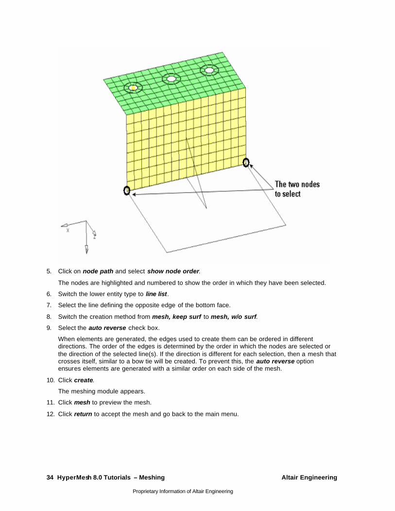
4. Select the end nodes located on back face edge that borders the bottom face, as indicated in the image below.
All the nodes between the two selected nodes are automatically selected.
34 HyperMesh 8.0 Tutorials – Meshing Altair Engineering
Proprietary Information of Altair Engineering
5. Click on node path and select show node order.
The nodes are highlighted and numbered to show the order in which they have been selected.
6. Switch the lower entity type to line list.
7. Select the line defining the opposite edge of the bottom face.
8. Switch the creation method from mesh, keep surf to mesh, w/o surf.
9. Select the auto reverse check box.
When elements are generated, the edges used to create them can be ordered in different directions. The order of the edges is determined by the order in which the nodes are selected or the direction of the selected line(s). If the direction is different for each selection, then a mesh that crosses itself, similar to a bow tie will be created. To prevent this, the auto reverse option ensures elements are generated with a similar order on each side of the mesh.
10. Click create.
The meshing module appears.
11. Click mesh to preview the mesh.
12. Click return to accept the mesh and go back to the main menu.
Altair Engineering HyperMesh 8.0 Tutorials – Meshing 35
Proprietary Information of Altair Engineering
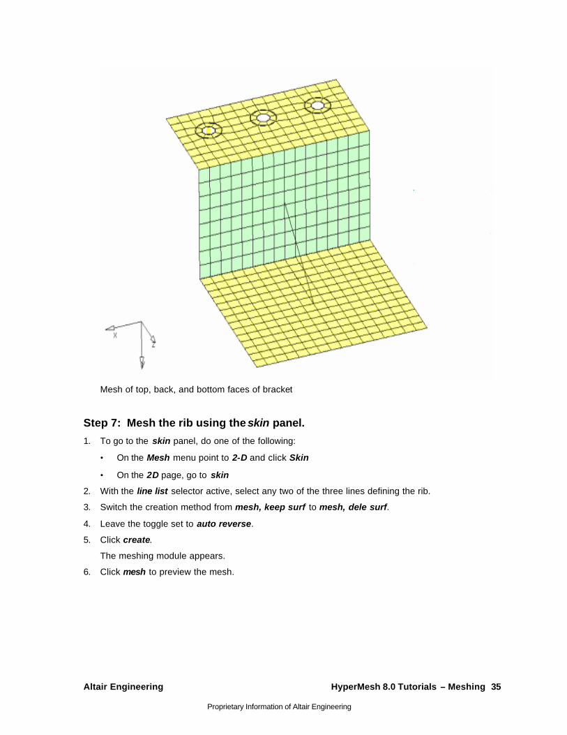
Mesh of top, back, and bottom faces of bracket
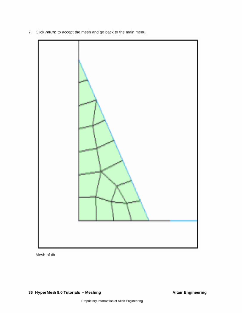
Step 7: Mesh the rib using the skin panel.
1. To go to the skin panel, do one of the following:
• On the Mesh menu point to 2-D and click Skin
• On the 2D page, go to skin
2. With the line list selector active, select any two of the three lines defining the rib.
3. Switch the creation method from mesh, keep surf to mesh, dele surf.
4. Leave the toggle set to auto reverse.
5. Click create.
The meshing module appears.
6. Click mesh to preview the mesh.
36 HyperMesh 8.0 Tutorials – Meshing Altair Engineering
Proprietary Information of Altair Engineering
7. Click return to accept the mesh and go back to the main menu.
Mesh of rib
Altair Engineering HyperMesh 8.0 Tutorials – Meshing 37
Proprietary Information of Altair Engineering
2-D Mesh in Curved - HM-3120 In this tutorial, you will learn:
• Create a mesh based only on element size
• Mesh a set of surfaces using the maximum deviation parameter
• Reduce the maximum angle perimeter
• Increase the maximum element size parameter
Chordal deviation is a meshing algorithm that allows HyperMesh to automatically vary node densities and biasing along curved surface edges to gain a more accurate representation of the surface being meshed.
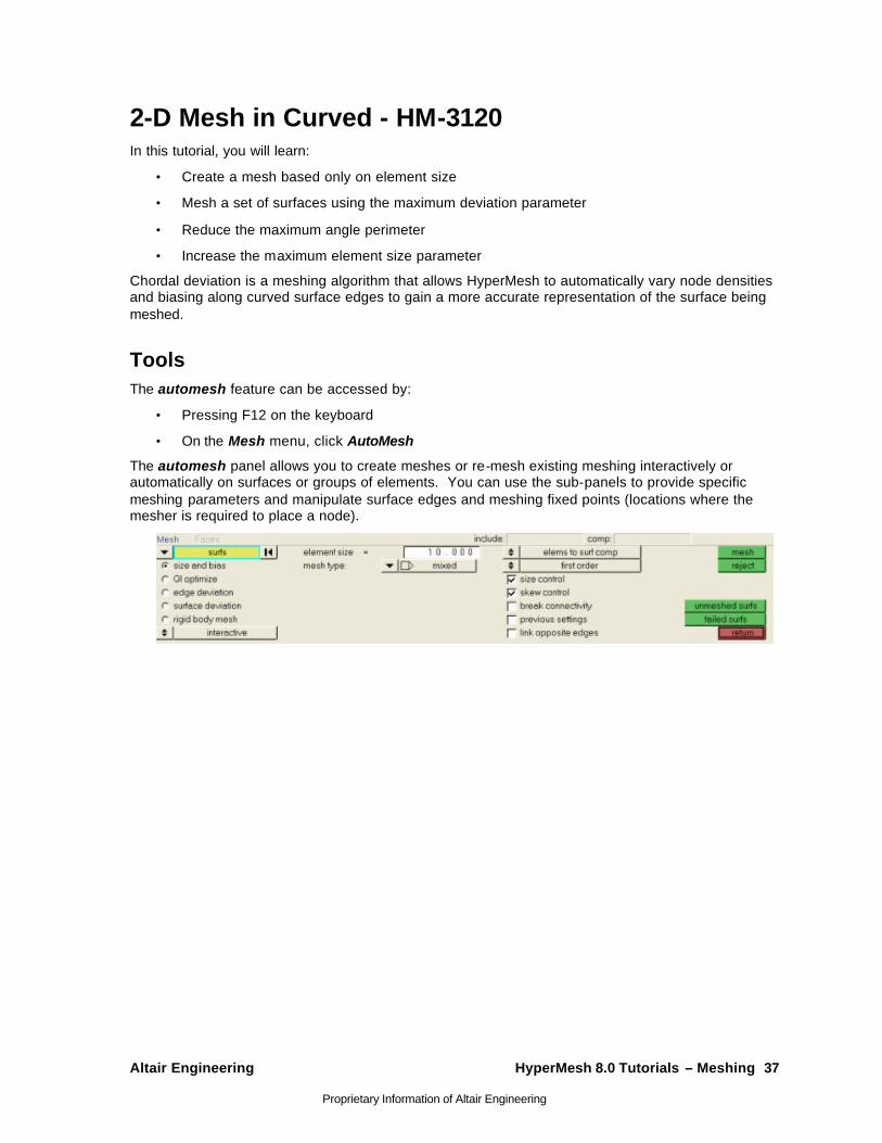
Tools The automesh feature can be accessed by:
• Pressing F12 on the keyboard
• On the Mesh menu, click AutoMesh
The automesh panel allows you to create meshes or re-mesh existing meshing interactively or automatically on surfaces or groups of elements. You can use the sub-panels to provide specific meshing parameters and manipulate surface edges and meshing fixed points (locations where the mesher is required to place a node).
38 HyperMesh 8.0 Tutorials – Meshing Altair Engineering
Proprietary Information of Altair Engineering
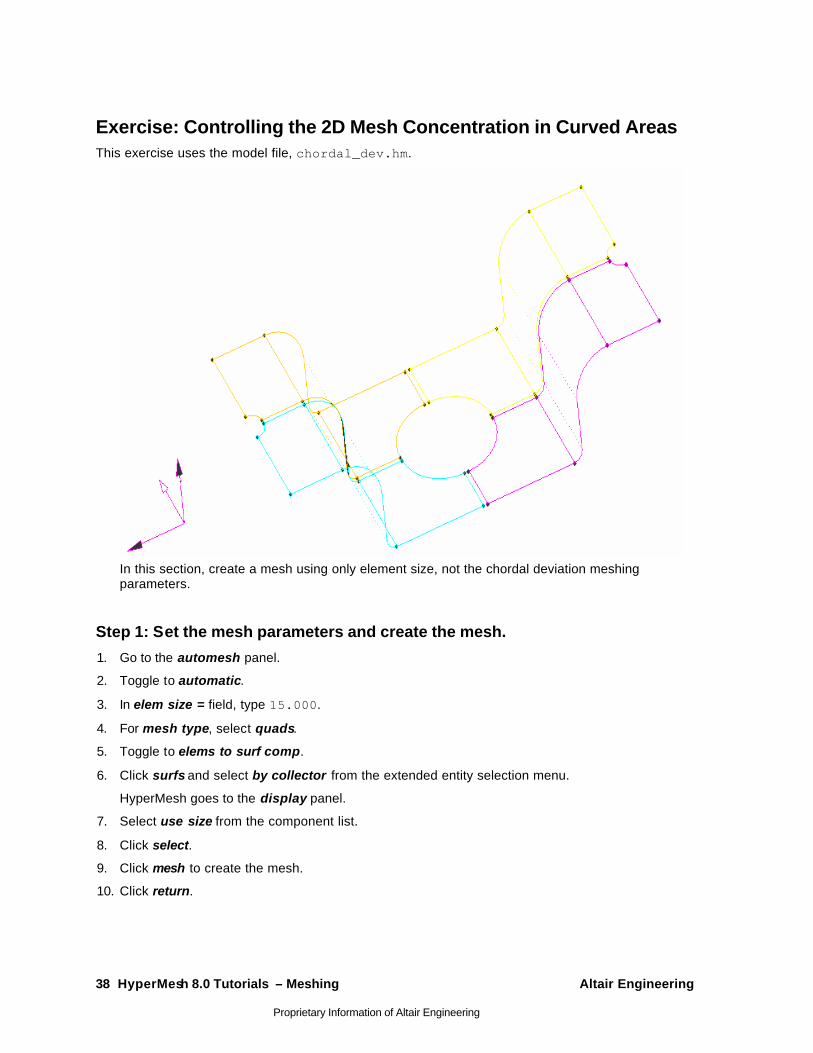
Exercise: Controlling the 2D Mesh Concentration in Curved Areas This exercise uses the model file, chordal_dev.hm.
In this section, create a mesh using only element size, not the chordal deviation meshing parameters.
Step 1: Set the mesh parameters and create the mesh.
1. Go to the automesh panel.
2. Toggle to automatic.
3. In elem size = field, type 15.000.
4. For mesh type, select quads.
5. Toggle to elems to surf comp.
6. Click surfs and select by collector from the extended entity selection menu.
HyperMesh goes to the display panel.
7. Select use size from the component list.
8. Click select.
9. Click mesh to create the mesh.
10. Click return.
Altair Engineering HyperMesh 8.0 Tutorials – Meshing 39
Proprietary Information of Altair Engineering
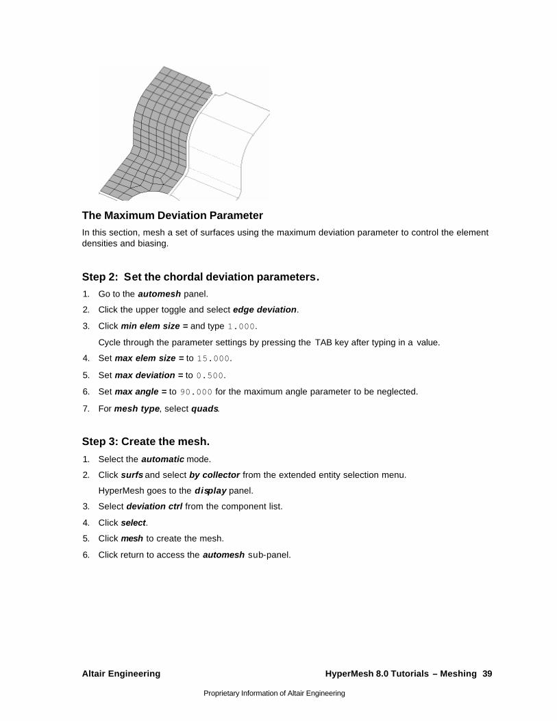
The Maximum Deviation Parameter In this section, mesh a set of surfaces using the maximum deviation parameter to control the element densities and biasing.
Step 2: Set the chordal deviation parameters. 1. Go to the automesh panel.
2. Click the upper toggle and select edge deviation.
3. Click min elem size = and type 1.000.
Cycle through the parameter settings by pressing the TAB key after typing in a value.
4. Set max elem size = to 15.000.
5. Set max deviation = to 0.500.
6. Set max angle = to 90.000 for the maximum angle parameter to be neglected.
7. For mesh type, select quads.
Step 3: Create the mesh.
1. Select the automatic mode.
2. Click surfs and select by collector from the extended entity selection menu.
HyperMesh goes to the display panel.
3. Select deviation ctrl from the component list.
4. Click select.
5. Click mesh to create the mesh.
6. Click return to access the automesh sub-panel.
40 HyperMesh 8.0 Tutorials – Meshing Altair Engineering
Proprietary Information of Altair Engineering
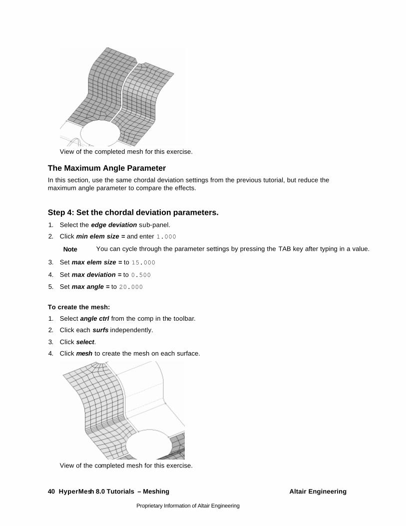
View of the completed mesh for this exercise.
The Maximum Angle Parameter In this section, use the same chordal deviation settings from the previous tutorial, but reduce the maximum angle parameter to compare the effects.
Step 4: Set the chordal deviation parameters. 1. Select the edge deviation sub-panel.
2. Click min elem size = and enter 1.000
Note You can cycle through the parameter settings by pressing the TAB key after typing in a value.
3. Set max elem size = to 15.000
4. Set max deviation = to 0.500
5. Set max angle = to 20.000
To create the mesh:
1. Select angle ctrl from the comp in the toolbar.
2. Click each surfs independently.
3. Click select.
4. Click mesh to create the mesh on each surface.
View of the completed mesh for this exercise.
Altair Engineering HyperMesh 8.0 Tutorials – Meshing 41
Proprietary Information of Altair Engineering
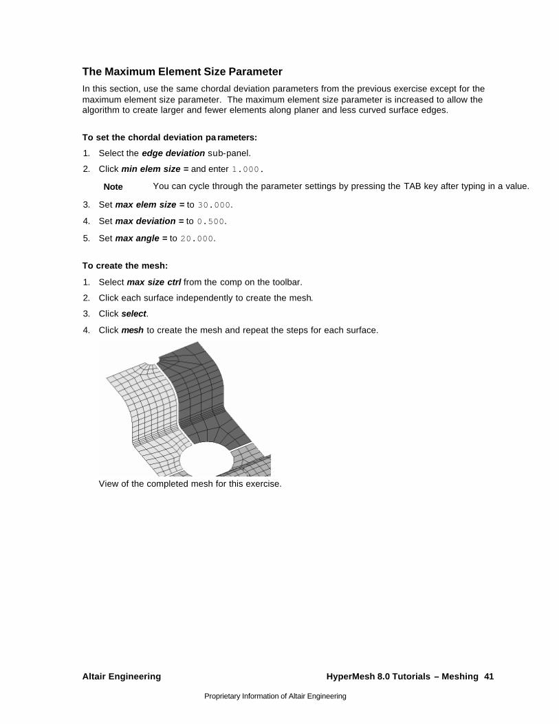
The Maximum Element Size Parameter In this section, use the same chordal deviation parameters from the previous exercise except for the maximum element size parameter. The maximum element size parameter is increased to allow the algorithm to create larger and fewer elements along planer and less curved surface edges.
To set the chordal deviation pa rameters:
1. Select the edge deviation sub-panel.
2. Click min elem size = and enter 1.000.
Note You can cycle through the parameter settings by pressing the TAB key after typing in a value.
3. Set max elem size = to 30.000.
4. Set max deviation = to 0.500.
5. Set max angle = to 20.000.
To create the mesh:
1. Select max size ctrl from the comp on the toolbar.
2. Click each surface independently to create the mesh.
3. Click select.
4. Click mesh to create the mesh and repeat the steps for each surface.
View of the completed mesh for this exercise.
42 HyperMesh 8.0 Tutorials – Meshing Altair Engineering
Proprietary Information of Altair Engineering
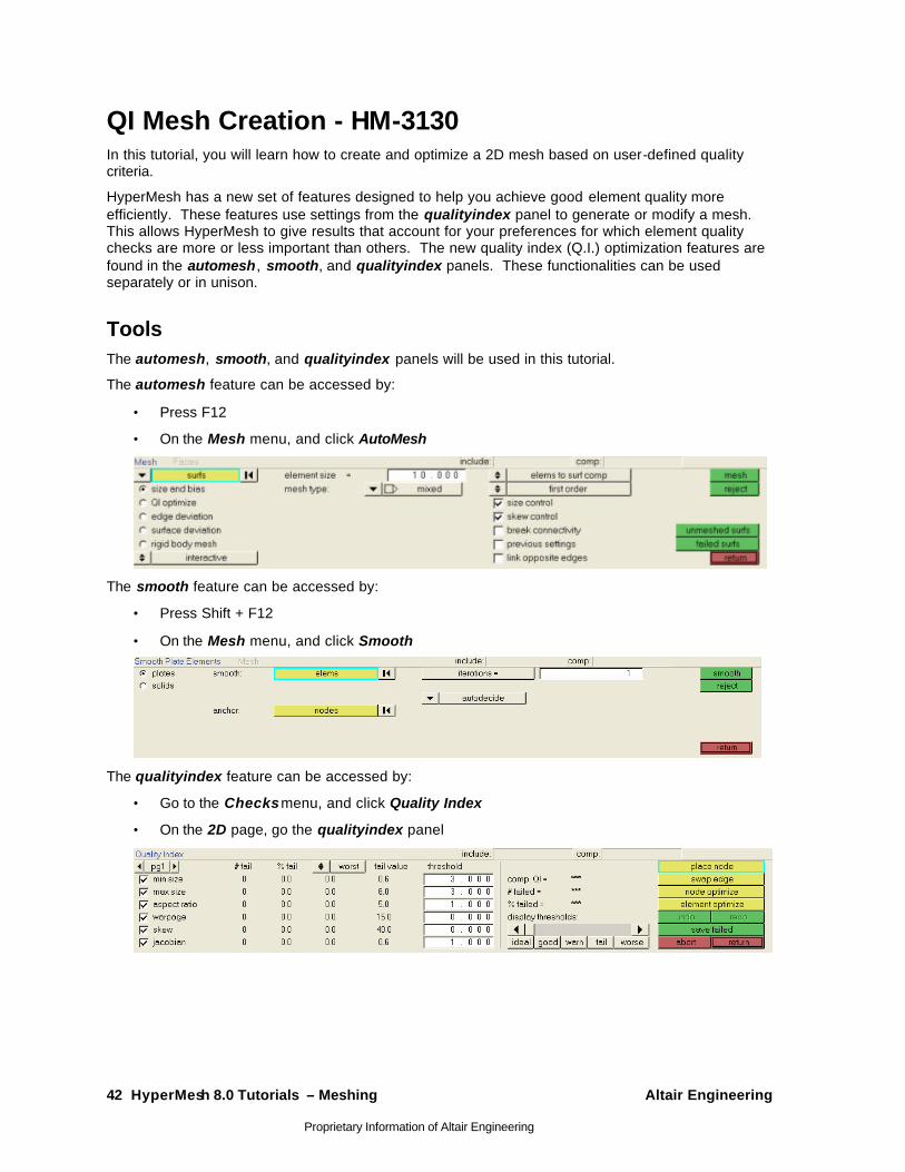
QI Mesh Creation - HM-3130 In this tutorial, you will learn how to create and optimize a 2D mesh based on user-defined quality criteria.
HyperMesh has a new set of features designed to help you achieve good element quality more efficiently. These features use settings from the qualityindex panel to generate or modify a mesh. This allows HyperMesh to give results that account for your preferences for which element quality checks are more or less important than others. The new quality index (Q.I.) optimization features are found in the automesh, smooth, and qualityindex panels. These functionalities can be used separately or in unison.
Tools The automesh, smooth, and qualityindex panels will be used in this tutorial.
The automesh feature can be accessed by:
• Press F12
• On the Mesh menu, and click AutoMesh
The smooth feature can be accessed by:
• Press Shift + F12
• On the Mesh menu, and click Smooth
The qualityindex feature can be accessed by:
• Go to the Checks menu, and click Quality Index
• On the 2D page, go the qualityindex panel
Altair Engineering HyperMesh 8.0 Tutorials – Meshing 43
Proprietary Information of Altair Engineering
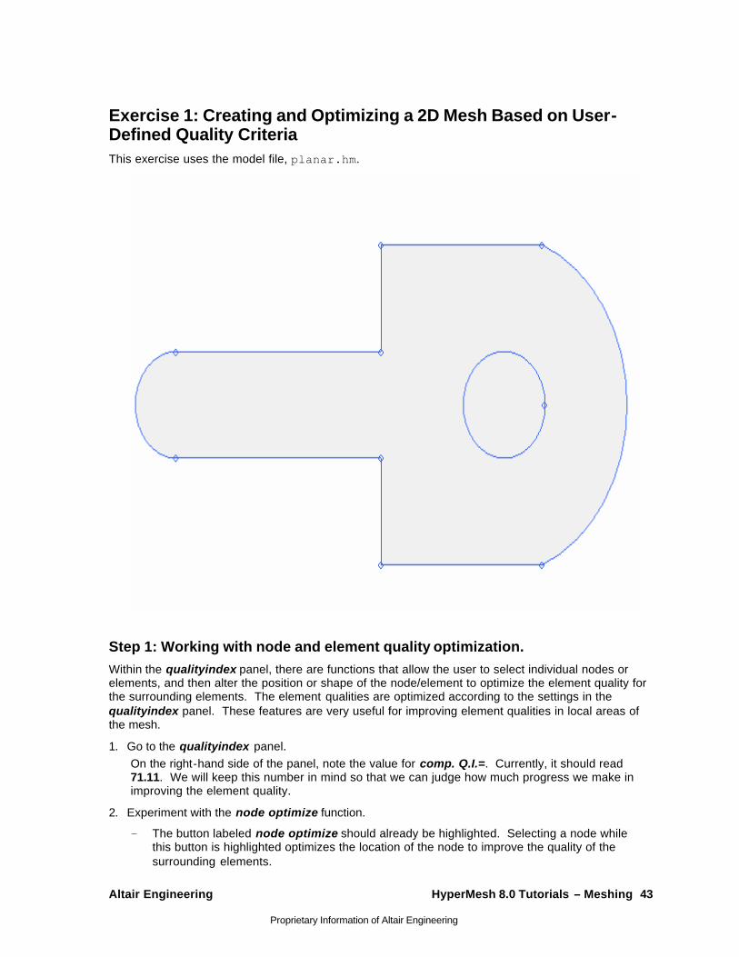
Exercise 1: Creating and Optimizing a 2D Mesh Based on User-Defined Quality Criteria This exercise uses the model file, planar.hm.
Step 1: Working with node and element quality optimization. Within the qualityindex panel, there are functions that allow the user to select individual nodes or elements, and then alter the position or shape of the node/element to optimize the element quality for the surrounding elements. The element qualities are optimized according to the settings in the qualityindex panel. These features are very useful for improving element qualities in local areas of the mesh.
1. Go to the qualityindex panel. On the right-hand side of the panel, note the value for comp. Q.I.=. Currently, it should read 71.11. We will keep this number in mind so that we can judge how much progress we make in improving the element quality.
2. Experiment with the node optimize function.
The button labeled node optimize should already be highlighted. Selecting a node while this button is highlighted optimizes the location of the node to improve the quality of the surrounding elements.

44 HyperMesh 8.0 Tutorials – Meshing Altair Engineering
Proprietary Information of Altair Engineering
Try selecting some of the nodes on the mesh. In particular, select nodes of elements that are highlighted red, since these have the worst quality. You should see each node move as it is selected, improving the surrounding mesh quality.
Notice what happens to the value of the comp. Q.I. It should improve as you select more nodes.
3. Experiment with the element optimize function.
Click the button labeled element optimize. Selecting an element while this button is highlighted optimizes the location of the element’s nodes to improve the quality of the element. It also considers the quality of the surrounding elements.
Try selecting some of the elements on the mesh. In particular, select elements that are highlighted red, since these have the worst quality. You should usually see the shape of the element change as it is selected, improving the surrounding mesh quality.
Notice what happens to the value of the comp. Q.I. It should improve as you select more elements.
4. Click return.
Step 2: Resetting the part by remeshing.
At this point, we need to regenerate the original mesh so we can try fixing the element quality using a different method. The new method is to use the smooth panel. Regenerating the original mesh allows us to compare the smooth functionality to the node and element optimization used in the previous section.
1. From the 2D page, go to the automesh panel.
2. Go to the size and bias sub-panel.
3. Select the surface in the graphics area.
4. Make sure the panel has the following settings:
The check-box for reset meshing parameters to: is checked on.
The elem size= field has a value of 18.
The type is set to quads.
The meshing mode is set to automatic.
5. Click the mesh button. The mesh should be regenerated.
6. Click return to exit from the automesh panel.
Step 3: Using QI optimization smoothing. The smooth panel also has quality index optimization features. Using this allows you to adjust the element quality according to the settings in the qualityindex panel for an entire group of selected elements.
1. Go to the smooth panel.
2. Go to the plates sub-panel.
Altair Engineering HyperMesh 8.0 Tutorials – Meshing 45
Proprietary Information of Altair Engineering
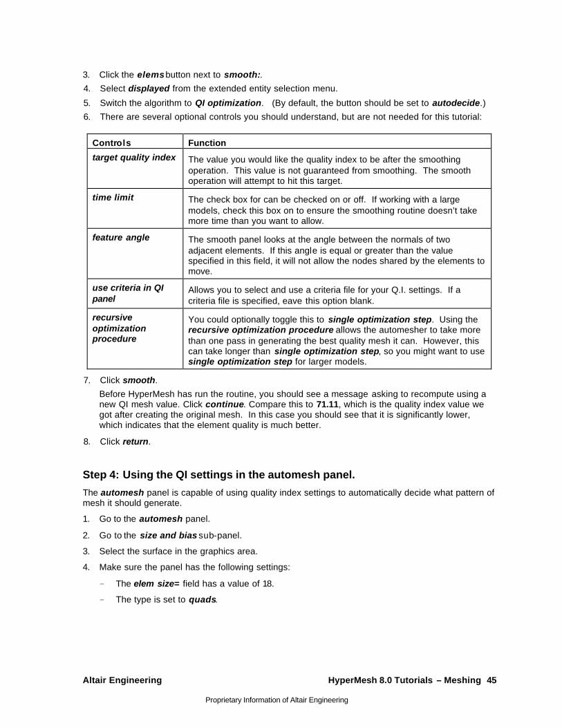
3. Click the elems button next to smooth:.
4. Select displayed from the extended entity selection menu.
5. Switch the algorithm to QI optimization. (By default, the button should be set to autodecide.)
6. There are several optional controls you should understand, but are not needed for this tutorial:
Controls Function
target quality index The value you would like the quality index to be after the smoothing operation. This value is not guaranteed from smoothing. The smooth operation will attempt to hit this target.
time limit The check box for can be checked on or off. If working with a large models, check this box on to ensure the smoothing routine doesn’t take more time than you want to allow.
feature angle The smooth panel looks at the angle between the normals of two adjacent elements. If this angle is equal or greater than the value specified in this field, it will not allow the nodes shared by the elements to move.
use criteria in QI panel
Allows you to select and use a criteria file for your Q.I. settings. If a criteria file is specified, eave this option blank.
recursive optimization procedure
You could optionally toggle this to single optimization step. Using the recursive optimization procedure allows the automesher to take more than one pass in generating the best quality mesh it can. However, this can take longer than single optimization step, so you might want to use single optimization step for larger models.
7. Click smooth.
Before HyperMesh has run the routine, you should see a message asking to recompute using a new QI mesh value. Click continue. Compare this to 71.11, which is the quality index value we got after creating the original mesh. In this case you should see that it is significantly lower, which indicates that the element quality is much better.
8. Click return.
Step 4: Using the QI settings in the automesh panel.
The automesh panel is capable of using quality index settings to automatically decide what pattern of mesh it should generate.
1. Go to the automesh panel.
2. Go to the size and bias sub-panel.
3. Select the surface in the graphics area.
4. Make sure the panel has the following settings:
The elem size= field has a value of 18.
The type is set to quads.

46 HyperMesh 8.0 Tutorials – Meshing Altair Engineering
Proprietary Information of Altair Engineering
5. Change the meshing mode from automatic to QI optimized. Like the smooth panel, the QI optimized meshing mode of the automesh panel has some controls of which you should be aware. They are, however, not needed in this tutorial.
Controls Function
use criteria in QI panel
Allows you to select and use a criteria file for your Q.I. settings. If a criteria file is specified, eave this option blank.
Smooth across common edges
Determines whether nodes generated on a surface edge can be moved off the surface edge when the algorithm smoothes the mesh
feature angle The smooth panel looks at the angle between the normals of two adjacent elements. If this angle is equal or greater than the value specified in this field, it will not allow the nodes shared by the elements to move.
Break connectivity Allows Mesher to mesh without affecting surrounding mesh.
6. Click mesh. The mesh should be regenerated.
7. Click return.
8. Check the quality index of the mesh to compare it to the previous mesh.
Go to the qualityindex panel.
Make sure the panel is set on results instead of criteria.
Look at the value for the comp. Q.I.= field. It should be 0.05, which is much lower that the 71.11 value of the mesh we originally generated.
Altair Engineering HyperMesh 8.0 Tutorials – Meshing 47
Proprietary Information of Altair Engineering
Batch Meshing - HM-3140 In this tutorial, you will learn how to:
• Define a configuration for the batch mesh
• Edit the criteria and parameter files
Batch Mesher is a tool that can perform geometry cleanup and automeshing (in batch mode) for given CAD files. Batch Mesher performs a variety of geometry cleanup operations to improve the quality of the mesh created for the selected element size and type. Cleanup operations include: equivalencing of "red" free edges, fixing small surfaces (relative to the element size), and detecting features.
Batch Mesher also performs specified surface editing/defeaturing operations such as: removal of pinholes (less than specified size), removal of edge fillets, and addition of a layer of washer elements around holes.
All user-defined criteria determine the quality index (QI) of a model. The QI value is used to assess the potential of each geometry cleanup and meshing tool, and apply them accordingly. QI optimized meshing and node placement optimization are performed to obtain the best quality meshing. Final results are stored in a HyperMesh database file.
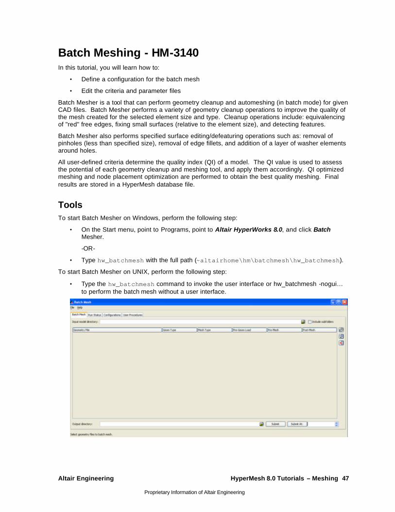
Tools To start Batch Mesher on Windows, perform the following step:
• On the Start menu, point to Programs, point to Altair HyperWorks 8.0, and click Batch Mesher.
-OR-
• Type hw_batchmesh with the full path (~altairhome\hm\batchmesh\hw_batchmesh).
To start Batch Mesher on UNIX, perform the following step:
• Type the hw_batchmesh command to invoke the user interface or hw_batchmesh -nogui… to perform the batch mesh without a user interface.
48 HyperMesh 8.0 Tutorials – Meshing Altair Engineering
Proprietary Information of Altair Engineering
Exercise
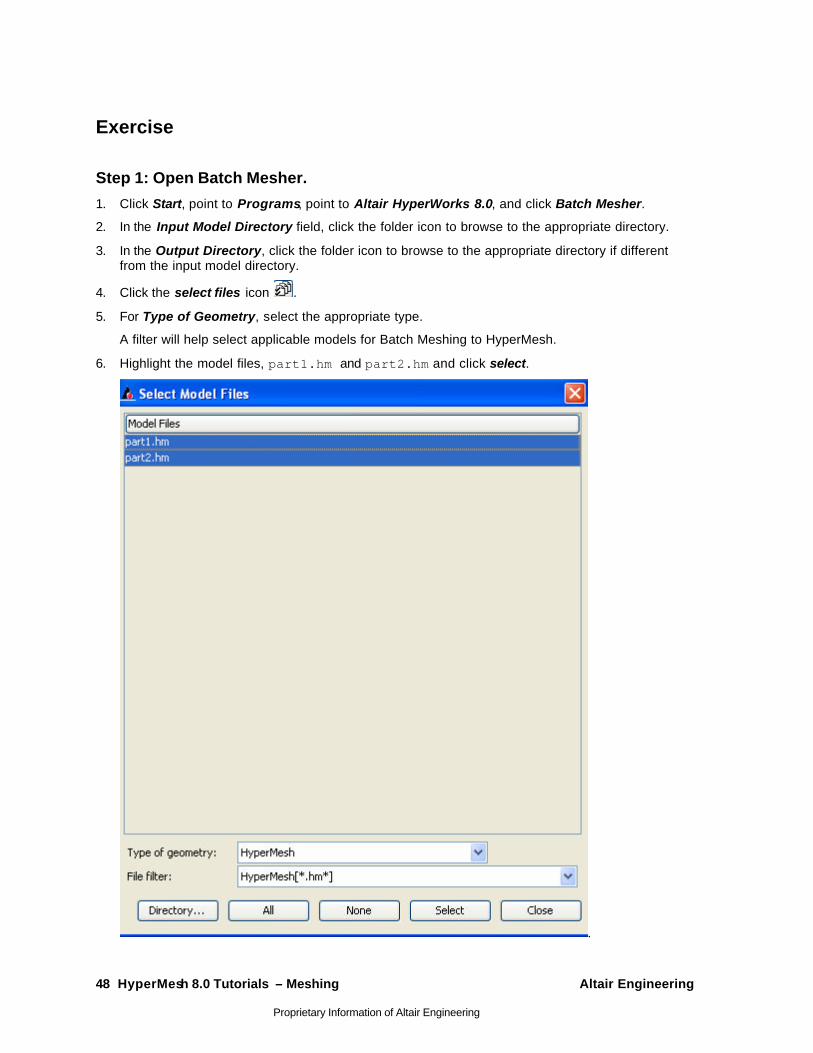
Step 1: Open Batch Mesher.
1. Click Start, point to Programs, point to Altair HyperWorks 8.0, and click Batch Mesher.
2. In the Input Model Directory field, click the folder icon to browse to the appropriate directory.
3. In the Output Directory, click the folder icon to browse to the appropriate directory if different from the input model directory.
4. Click the select files icon .
5. For Type of Geometry, select the appropriate type.
A filter will help select applicable models for Batch Meshing to HyperMesh.
6. Highlight the model files, part1.hm and part2.hm and click select.
.

Altair Engineering HyperMesh 8.0 Tutorials – Meshing 49
Proprietary Information of Altair Engineering
Step 2 (Optional): Define a configuration for the batch mesh run.
1. Click the Configurations tab.
2. Click the Add Entry icon, .
3. In the Mesh Type field, type a name for the mesh type.
4. Select the Criteria File field, and click the Find Criteria Param File icon, .
5. Select a file.
6. Select the Parameter File field, and click the Find Criteria Param File icon, .
7. Select a file.
A new mesh type is now available for selection on the Batch Mesh tab.
Step 3: On the Batch Mesh tab, begin defining a configuration for the batch mesh run.
1. In the Mesh Type field, select a mesh type.
2. Right -click and select the file(s) that will be meshed with the same criteria.
3. In the Pre-Geom Load, Pre-Mesh, or Post-Mesh drop down lists, select any tcl files necessary in the batch run.
4. Click Submit to initiate the run.
-OR-
5. Click Submit At to submit the job at a specified time.
The application automatically switches to the Run Status tab.
As the parts run, the status changes from Working to Pending to Done.
6. Once the part is at the Working state, select the part and select Details.
A detailed summary appears with the status of the model through its Batch Mesher steps, the overall failed elements, and quality index.
7. Once the part is at the Done state, click Load Mesh to load the mesh into HyperMesh for model interrogation.
8. Once all parts have been meshed, select Run Details to obtain an overall run status.
Any file can be paused or cancelled. If the file is paused, it can be resumed now or at a specific time.
Once the Batch Mesher session has been setup with File directories and mesh types, it can be saved as a Config that can be loaded at a future time.
It is also possible to load an entire set of models that has already been batchmeshed in order to take advantage of the Load Mesh option in the Run Status tab.
Step 4: Edit the Criteria and Parameter Files.
1. Go to the Configurations tab.
2. Click Mesh Type.
50 HyperMesh 8.0 Tutorials – Meshing Altair Engineering
Proprietary Information of Altair Engineering
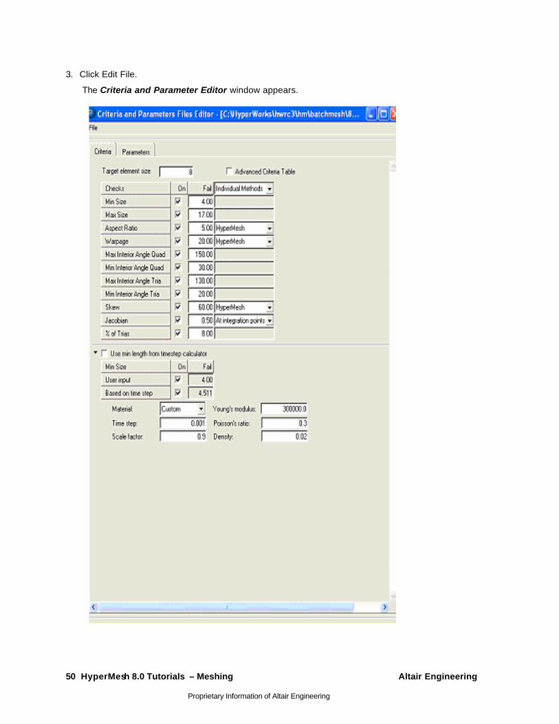
3. Click Edit File.
The Criteria and Parameter Editor window appears.
Altair Engineering HyperMesh 8.0 Tutorials – Meshing 51
Proprietary Information of Altair Engineering
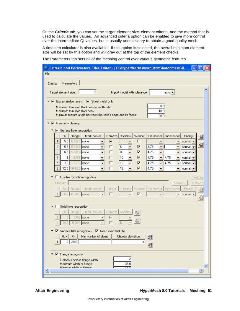
On the Criteria tab, you can set the target element size, element criteria, and the method that is used to calculate the values. An advanced criteria option can be enabled to give more control over the intermediate QI values, but is usually unnecessary to obtain a good quality mesh.
A timestep calculator is also available. If this option is selected, the overall minimum element size will be set by this option and will gray out at the top of the element checks.
The Parameters tab sets all of the meshing control over various geometric features.
52 HyperMesh 8.0 Tutorials – Meshing Altair Engineering
Proprietary Information of Altair Engineering
Tetrameshing - HM-3200 In this tutorial, you will learn about:
• Volume tetra mesher
• Standard tetra mesher
• Checking tetra element quality
• Re-meshing tetra elements
HyperMesh provides two methods of generating a tetrahedral element mesh. The volume tetra mesher works directly with surface or solid geometry to automatically generate a tetrahedral mesh without further interaction from the user. Even with complex geometry, this method can often generate a high quality tetra mesh quickly and easily.
The standard tetra mesher requires a surface mesh of tria or quad elements as input, then provides you with a number of options to control the resulting tetrahedral mesh. This offers a great deal of control over the tetrahedral mesh, and provides the means to generate a tetrahedral mesh for even the most complex models.
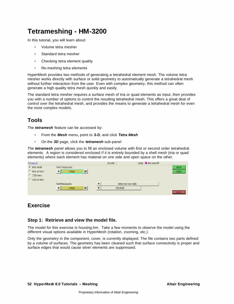
Tools The tetramesh feature can be accessed by:
• From the Mesh menu, point to 3-D, and click Tetra Mesh
• On the 3D page, click the tetramesh sub-panel
The tetramesh panel allows you to fill an enclosed volume with first or second order tetrahedral elements. A region is considered enclosed if it is entirely bounded by a shell mesh (tria or quad elements) where each element has material on one side and open space on the other.
Exercise
Step 1: Retrieve and view the model file.
The model for this exercise is housing.hm. Take a few moments to observe the model using the different visual options available in HyperMesh (rotation, zooming, etc.).
Only the geometry in the component, cover, is currently displayed. The file contains two parts defined by a volume of surfaces. The geometry has been cleaned such that surface connectivity is proper and surface edges that would cause sliver elements are suppressed.

Altair Engineering HyperMesh 8.0 Tutorials – Meshing 53
Proprietary Information of Altair Engineering
Step 2: Use the volume tetra mesher and equilateral triangles to create a tetra mesh for the cover.
1. On the 3D page, go to the tetramesh panel.
2. Go to the volume tetra sub-panel.
3. With the surf selector active, select one of the surfaces in the model.
The connected surfaces are selected automatically.
4. Verify that 2D: is set to trias and 3D: is set to tetras.
These control the type of element that will be created for the surface mesh and solid mesh of the part.
5. Verify that the use curvature and use proximity options are off.
6. For element size= specify 10.
7. Click mesh to create the tetra mesh.
The volume tetra mesher creates two components. One is for the shell mesh, and the other is for the tetra mesh.
8. From the toolbar, click the shaded elements icon, .
9. Take a moment to inspect the mesh pattern that the volume tetra mesher created.
54 HyperMesh 8.0 Tutorials – Meshing Altair Engineering
Proprietary Information of Altair Engineering
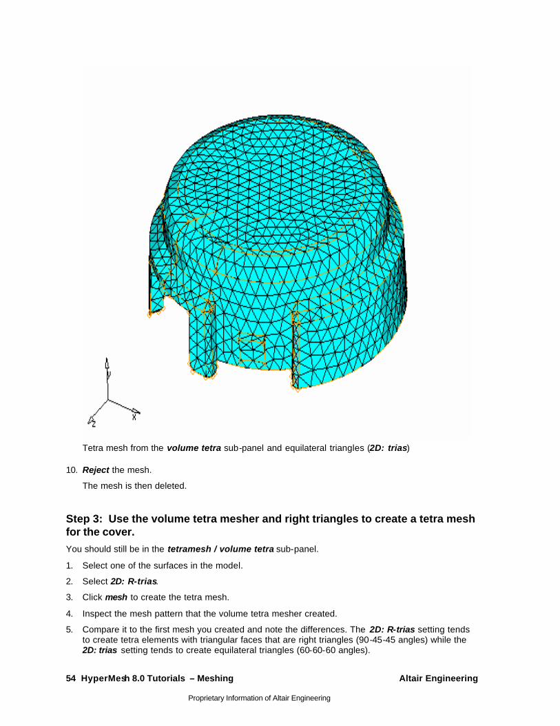
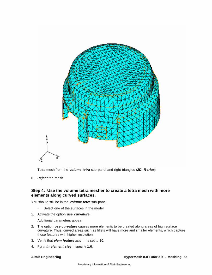
Tetra mesh from the volume tetra sub-panel and equilateral triangles (2D: trias)
10. Reject the mesh.
The mesh is then deleted.
Step 3: Use the volume tetra mesher and right triangles to create a tetra mesh for the cover. You should still be in the tetramesh / volume tetra sub-panel.
1. Select one of the surfaces in the model.
2. Select 2D: R-trias.
3. Click mesh to create the tetra mesh.
4. Inspect the mesh pattern that the volume tetra mesher created.
5. Compare it to the first mesh you created and note the differences. The 2D: R-trias setting tends to create tetra elements with triangular faces that are right triangles (90-45-45 angles) while the 2D: trias setting tends to create equilateral triangles (60-60-60 angles).
Altair Engineering HyperMesh 8.0 Tutorials – Meshing 55
Proprietary Information of Altair Engineering
Tetra mesh from the volume tetra sub-panel and right triangles (2D: R-trias)
6. Reject the mesh.
Step 4: Use the volume tetra mesher to create a tetra mesh with more elements along curved surfaces.
You should still be in the volume tetra sub-panel.
• Select one of the surfaces in the model.
1. Activate the option use curvature.
Additional parameters appear.
2. The option use curvature causes more elements to be created along areas of high surface curvature. Thus, curved areas such as fillets will have more and smaller elements, which capture those features with higher resolution.
3. Verify that elem feature ang = is set to 30.
4. For min element size = specify 1.0.
56 HyperMesh 8.0 Tutorials – Meshing Altair Engineering
Proprietary Information of Altair Engineering
5. Click mesh to create the tetra mesh.
6. Shade the tetrahedral elements.
7. Inspect the mesh pattern that the volume tetra mesher created.
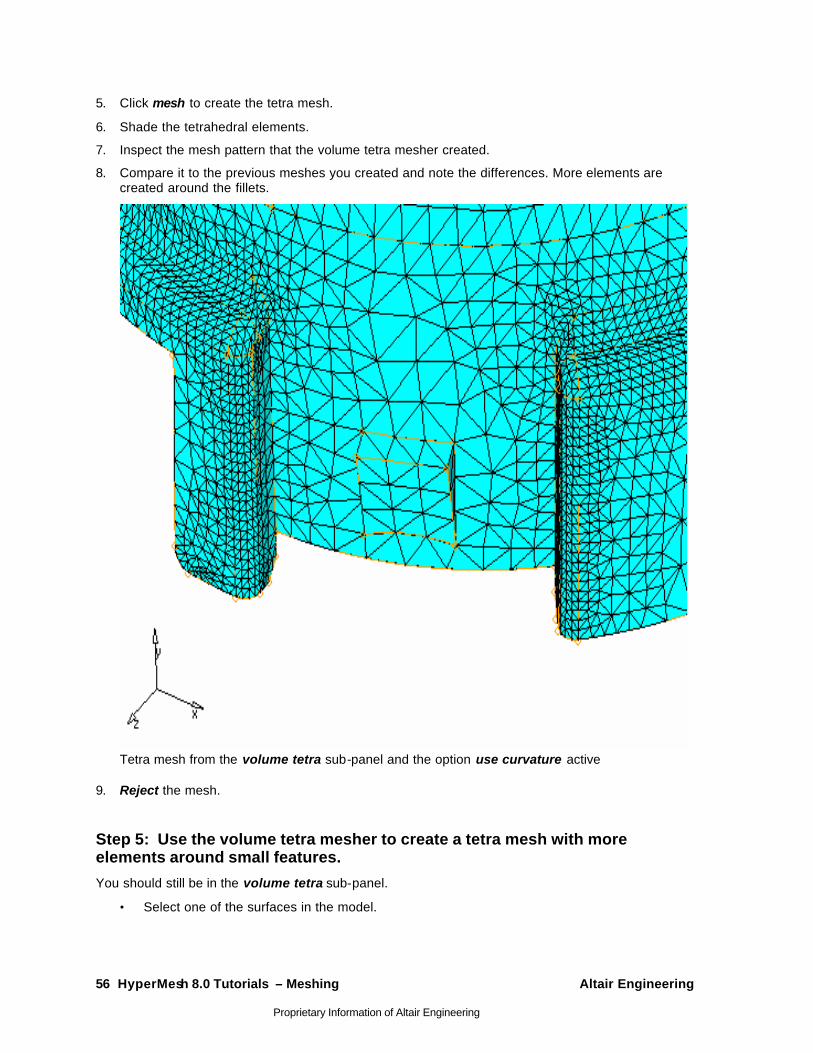
8. Compare it to the previous meshes you created and note the differences. More elements are created around the fillets.
Tetra mesh from the volume tetra sub-panel and the option use curvature active
9. Reject the mesh.
Step 5: Use the volume tetra mesher to create a tetra mesh with more elements around small features.
You should still be in the volume tetra sub-panel.
• Select one of the surfaces in the model.
Altair Engineering HyperMesh 8.0 Tutorials – Meshing 57
Proprietary Information of Altair Engineering
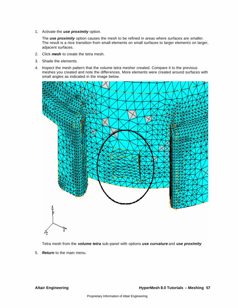
1. Activate the use proximity option.
The use proximity option causes the mesh to be refined in areas where surfaces are smaller. The result is a nice transition from small elements on small surfaces to larger elements on larger, adjacent surfaces.
2. Click mesh to create the tetra mesh.
3. Shade the elements.
4. Inspect the mesh pattern that the volume tetra mesher created. Compare it to the previous meshes you created and note the differences. More elements were created around surfaces with small angles as indicated in the image below.
Tetra mesh from the volume tetra sub-panel with options use curvature and use proximity
5. Return to the main menu.

58 HyperMesh 8.0 Tutorials – Meshing Altair Engineering
Proprietary Information of Altair Engineering
Step 6: Prepare the display to tetra mesh the hub component using the standard tetra mesher.
• Go to the display panel.
1. Toggle from elems to geom for components.
2. Click none to turn off the display for all components for geometry.
3. Turn on the display of the geometry for the hub component.
4. Toggle from geom to elems for components.
5. Click none to turn off the display for all components for elements.
6. Turn on the display for the hub and tetras components for elements.
There are tria shell elements in the hub component. Currently, there are no elements in the tetras component.
7. Return to the main menu.
Step 7 (Optional): Review the connectivity and quality of the tria mesh to validate its integrity for the standard tetra mesher.
• Use the edges and check elems panels to make sure that there are no free edges or very small angles in the tria shell mesh.
1. On the Tool page enter the edges panel.
2. With the comps selector active, pick any tria element on the hub component.
3. Click find edges.
A message in the header bar should state "No edges found. Selected elements may enclose a volume."
This is desired as the tetra mesher requires a closed volume of shell elements.
4. Return to the main menu.
5. Enter the check elements panel.
6. Verify that you are in the 2-d sub-panel.
7. dentify elements having an aspect ratio greater than 5.
Aspect ratio is the ratio of the longest edge of an element to its shortest edge. This check helps you to identify sliver elements.
All of the hub’s shell elements pass the check; all of the elements have an aspect ratio less than 5.
8. Identify tria elements having an angle less than 20. (trias: min angle).
This check also helps you to identify sliver elements.
All the hub’s shell elements pass the check; all the elements have angles greater than 20.
The surface mesh is suitable for creating a tetra mesh.
9. Return to the main menu.
Altair Engineering HyperMesh 8.0 Tutorials – Meshing 59
Proprietary Information of Altair Engineering
Step 8: Create a tetra mesh for the hub using the standard tetra mesher.
• Use the tetramesh / tetra mesh sub-panel to generate the mesh.
1. Set the current component to tetras by clicking on the comp: on the message bar under the toolbar.
2. On the 3D page, go to the tetramesh panel.
3. Go to the tetra mesh sub-panel.
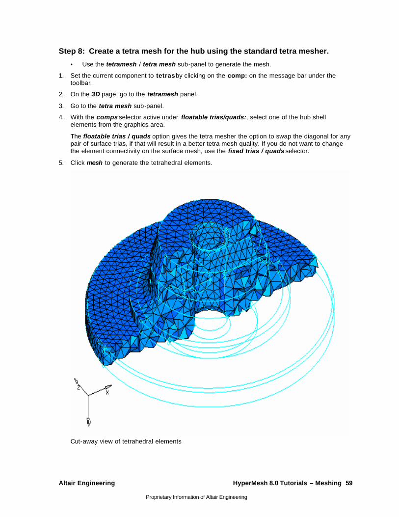
4. With the comps selector active under floatable trias/quads:, select one of the hub shell elements from the graphics area.
The floatable trias / quads option gives the tetra mesher the option to swap the diagonal for any pair of surface trias, if that will result in a better tetra mesh quality. If you do not want to change the element connectivity on the surface mesh, use the fixed trias / quads selector.
5. Click mesh to generate the tetrahedral elements.
Cut-away view of tetrahedral elements

60 HyperMesh 8.0 Tutorials – Meshing Altair Engineering
Proprietary Information of Altair Engineering
Step 9: Check the quality of the hub’s tetra elements.
• From the display panel, display only the elements in the tetras component.
1. On to the Tool page, go to the check elems panel.
2. Go to the 3-d sub-panel.
3. Identify the smallest element length among the displayed elements.
If the minimum length is acceptable for a target element size of 5.0, then no further action is necessary.
4. Identify the smallest angle (tria faces: min angle) among the displayed elements.
If the minimum tria face angle is no less than 10°, then the mesh quality should be acceptable.
5. Identify elements having a tet collapse smaller than 0.3.
The tet collapse criteria is a normalized volume check for tetrahedral elements. A value of one indicates a perfectly formed element with maximum possible volume. A value of zero indicates a completely collapsed element with no volume.
The header message bar indicates that one element has a tetra collapse smaller than 0.3.
Step 10: Isolate the element with the tetra collapse smaller than 0.3 and find the elements surrounding it.
You should still be in the check elements panel.
• With 0.3 still specified for tet collapse, click tet collapse again.
1. Click save failed.
The element that failed the tetra collapse check is saved in the user mark, and can be retrieved in any panel using the extended selection menu.
2. Return to the main menu.
3. On the Tool page, enter the mask panel (F5 key).
4. Set the entity selector to elems and select elems >> retrieve.
The element that was saved in the check elems panel is retrieved.
5. Select elems >> reverse.
6. Mask the elements.
Only the one tetra element that failed the tetra collapse check should be displayed.
7. Return to the main menu.
8. On the QA/Model page of the macro menu, click find attached.
The layer of elements that is attached to the one displayed element is identified and displayed.
9. Click find attached again.
The layer of elements that is attached to the displayed elements is identified and displayed. The find attached macro’s functionality can be duplicated using the find panel, find attached(fe) sub-panel on the Tool page.

Altair Engineering HyperMesh 8.0 Tutorials – Meshing 61
Proprietary Information of Altair Engineering
Step 11: Re-mesh the hub’s displayed tetra elements to improve their tetra collapse.
• Use the tetramesh / tetra remesh sub-panel to re-mesh only the displayed tetra elements.
1. On the 3D page enter the tetramesh panel.
2. Go to the tetra remesh sub-panel.
3. Select elems >> displayed.
4. Remesh the elements to regenerate this area of the mesh.
Note that the re-meshing operation works on only one group of elements (one volume) at a time.
5. Return to the main menu.
6. On the Tool page enter the check elems panel.
7. Click tet collapse to find out if the tetra collapse has improved for the displayed elements.
The message in the header bar should indicate that the minimum tetra collapse is larger than the value reported before the tetra elements were re-meshed.
8. Return to the main menu.
Step 12 (Optional): Save your work. Now that the tetra mesh is complete, it is a good time to save the model.
Summary A tetra mesh has been created for both parts in the file. Different procedures for tetra meshing were used. Either method can be used to mesh parts, depending on the needs of the analysis. Also, the tetra re-mesh function was used to show how to quickly fix the quality of tetra elements.
62 HyperMesh 8.0 Tutorials – Meshing Altair Engineering
Proprietary Information of Altair Engineering
Creating a Hex-Penta Mesh using Surfaces - HM-3210 In this tutorial, you will learn how to:
• Create solids using different functions
• Check and fix improper model connectivity
For some analyses, it is desirable to use a mesh of hexahedral and pentahedral elements. This is especially true for parts, which have a large thickness compared to the element size being used, or for parts that have many features and/or changes in thickness. Castings or forgings are good examples.
Tools The elem offset feature can be accessed by:
• On the Mesh menu, click Offset
• On the 2D page, go to elem offset
The elem offset panel allows you to create and modify elements by offsetting from a mesh of plate or shell elements. The element normals provide directional information.
The spin feature can be accessed by:
• On the Mesh menu, point to 2-D, click Spin
• On the 2D page, go to spin
The spin panel allows you to create a surface and/or mesh or elements by spinning a series of nodes, a line or lines, or a group of elements about a vector to create a circular structure.
The linear solid feature can be accessed by:
• On the Mesh menu, point to 3-D, click Linear Solid
• On the 3D page, go to linear solid
The linear solid panel allows you to create solid elements between two groups of plate elements.
The solid map feature can be accessed by:
• On the Mesh menu, point to 3-D, click Linear Solid
• On the 3D page, go to solid map
The solid map panel allows you to create a mesh of solid elements by first extruding an existing 2-D finite element mesh, and then mapping the extruded mesh into a volume.
Altair Engineering HyperMesh 8.0 Tutorials – Meshing 63
Proprietary Information of Altair Engineering
The faces feature can be accessed by:
• On the Checks menu, click on Faces
• On the Tool page, go to faces
The faces panel allows you to find the free faces in a group of elements, and operates in the same manner as edges, but in 3-D. It also allows you to find and delete duplicate nodes. This function will find free faces in your model where elements are separated, and highlight those areas. Once the free faces are located, you can use equivalence to remove the duplicate nodes, based on a tolerance specified by you. The preview option is available to allow you to see which nodes will be equivalenced.
The project feature can be accessed by:
• On the Tools menu, click Project
• On the Tools page, click project
The project panel allows you to project data entities to a plane, vector, surface, or line.
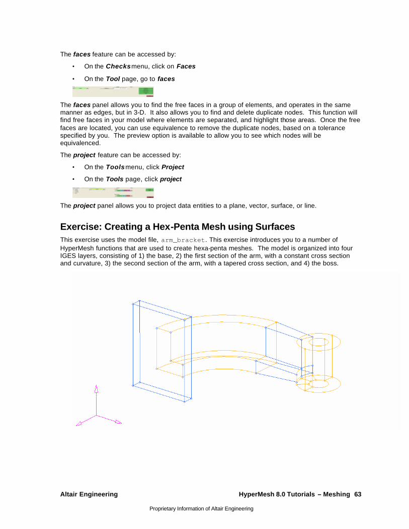
Exercise: Creating a Hex-Penta Mesh using Surfaces This exercise uses the model file, arm_bracket. This exercise introduces you to a number of HyperMesh functions that are used to create hexa-penta meshes. The model is organized into four IGES layers, consisting of 1) the base, 2) the first section of the arm, with a constant cross section and curvature, 3) the second section of the arm, with a tapered cross section, and 4) the boss.

64 HyperMesh 8.0 Tutorials – Meshing Altair Engineering
Proprietary Information of Altair Engineering
Step 1: Retrieve and review model file. Open the arm_bracket file.
Step 2: Mesh the top surface of the base, including the L-shaped surface. 1. Set the active component collector to base in one of the following ways:
• In the header bar click on comp: and set the current component in the popup.
• In the Model Browser right click on base and select Make Current.
2. Display the geometry only for the components base, in one of the following ways:
• With the Model Browser in geometry display mode , right click on base and select show only.
• On the toolbar, click on the Collector Visibility icon , toggle entity type to geoms, click on none and then left click base.
3. Access the automesh panel in one of the following ways:
• On the Mesh menu click Automesh
• On the 2D page enter the automesh panel.
4. Select the surfaces on the top of the base, including the L-shaped surface at the intersection of the base and the arm.
For this part of the exercise it might be easier to view the geometry in a shaded mode by clicking
on the Shaded Geometry and Surface Edges Icon .
5. Select the size and bias sub panel.
6. Set the meshing mode to automatic.
7. For elem size = specify 10.
8. For element type specify quads.
9. Mesh the surfaces.
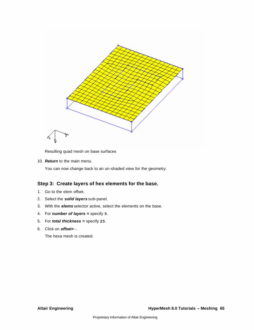
Altair Engineering HyperMesh 8.0 Tutorials – Meshing 65
Proprietary Information of Altair Engineering
Resulting quad mesh on base surfaces
10. Return to the main menu.
You can now change back to an un-shaded view for the geometry.
Step 3: Create layers of hex elements for the base.
1. Go to the elem offset.
2. Select the solid layers sub-panel.
3. With the elems selector active, select the elements on the base.
4. For number of layers = specify 5.
5. For total thickness = specify 25.
6. Click on offset+ -.
The hexa mesh is created.
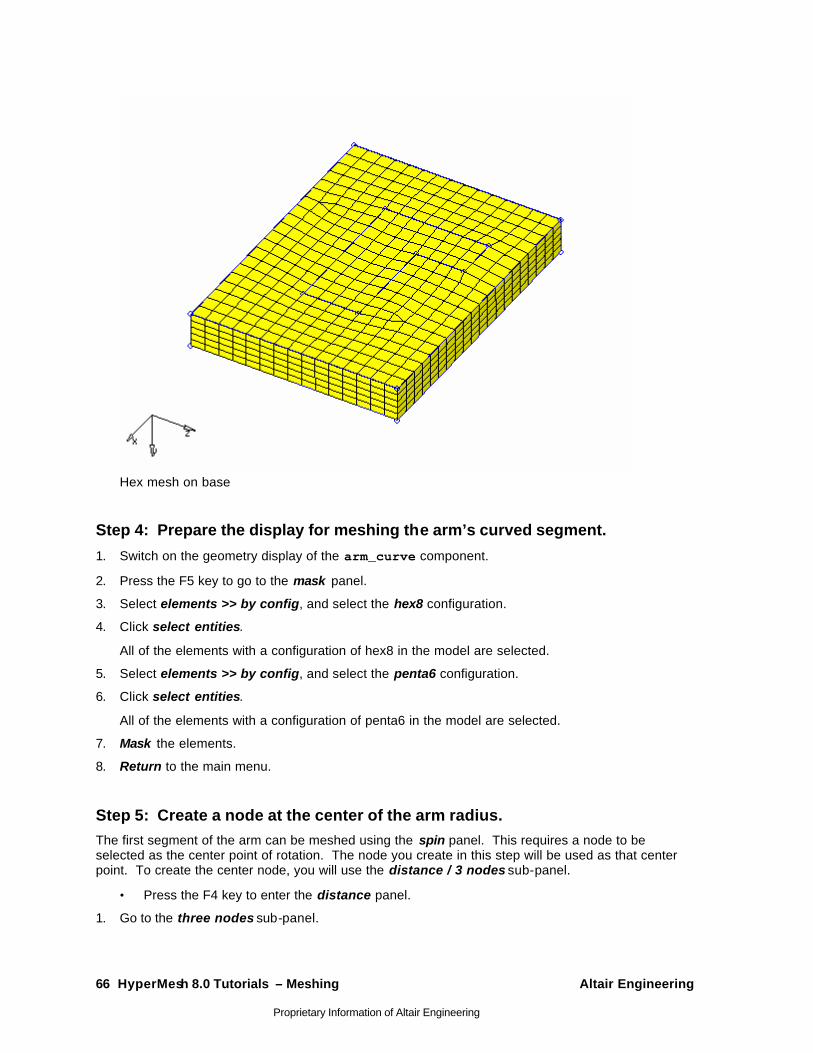
66 HyperMesh 8.0 Tutorials – Meshing Altair Engineering
Proprietary Information of Altair Engineering
Hex mesh on base
Step 4: Prepare the display for meshing the arm’s curved segment.
1. Switch on the geometry display of the arm_curve component.
2. Press the F5 key to go to the mask panel.
3. Select elements >> by config, and select the hex8 configuration.
4. Click select entities.
All of the elements with a configuration of hex8 in the model are selected.
5. Select elements >> by config, and select the penta6 configuration.
6. Click select entities.
All of the elements with a configuration of penta6 in the model are selected.
7. Mask the elements.
8. Return to the main menu.
Step 5: Create a node at the center of the arm radius. The first segment of the arm can be meshed using the spin panel. This requires a node to be selected as the center point of rotation. The node you create in this step will be used as that center point. To create the center node, you will use the distance / 3 nodes sub-panel.
• Press the F4 key to enter the distance panel.
1. Go to the three nodes sub-panel.
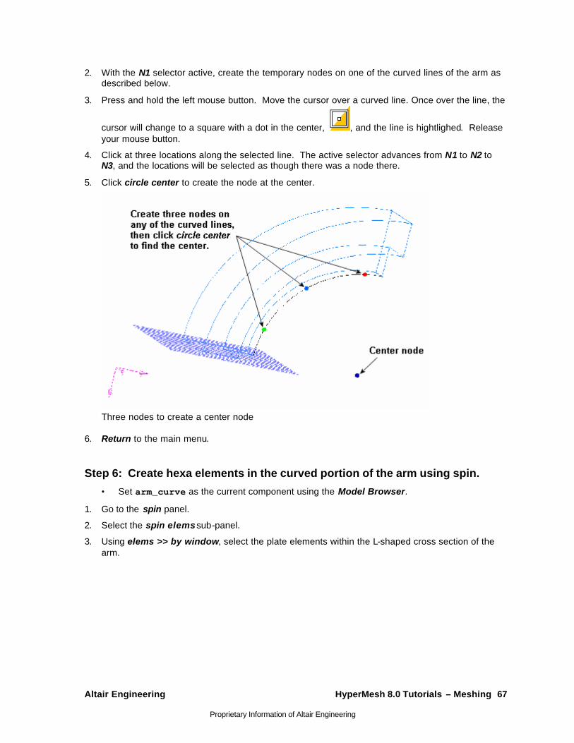
Altair Engineering HyperMesh 8.0 Tutorials – Meshing 67
Proprietary Information of Altair Engineering
2. With the N1 selector active, create the temporary nodes on one of the curved lines of the arm as described below.
3. Press and hold the left mouse button. Move the cursor over a curved line. Once over the line, the
cursor will change to a square with a dot in the center, , and the line is hightlighed. Release your mouse button.
4. Click at three locations along the selected line. The active selector advances from N1 to N2 to N3, and the locations will be selected as though there was a node there.
5. Click circle center to create the node at the center.
Three nodes to create a center node
6. Return to the main menu.
Step 6: Create hexa elements in the curved portion of the arm using spin.
• Set arm_curve as the current component using the Model Browser.
1. Go to the spin panel.
2. Select the spin elems sub-panel.
3. Using elems >> by window, select the plate elements within the L-shaped cross section of the arm.
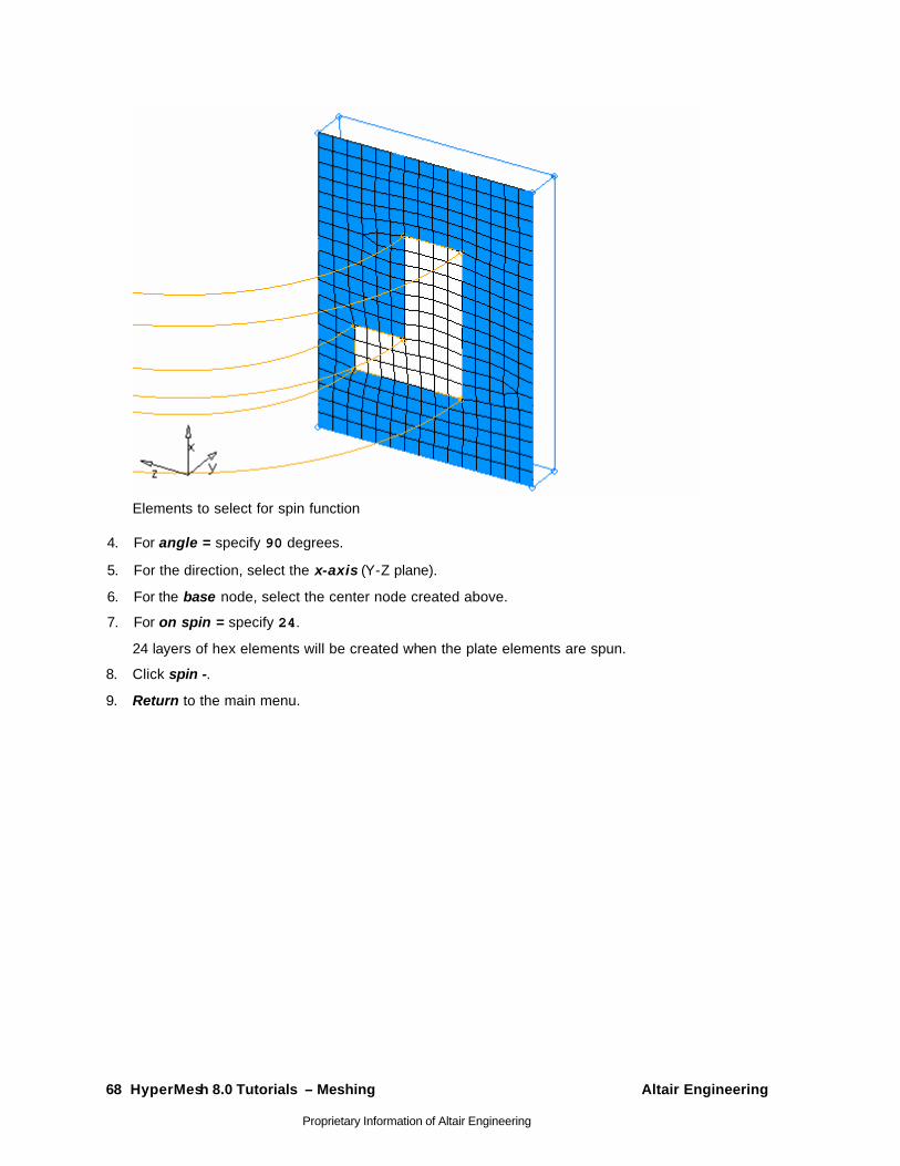
68 HyperMesh 8.0 Tutorials – Meshing Altair Engineering
Proprietary Information of Altair Engineering
Elements to select for spin function
4. For angle = specify 90 degrees.
5. For the direction, select the x-axis (Y-Z plane).
6. For the base node, select the center node created above.
7. For on spin = specify 24.
24 layers of hex elements will be created when the plate elements are spun.
8. Click spin -.
9. Return to the main menu.
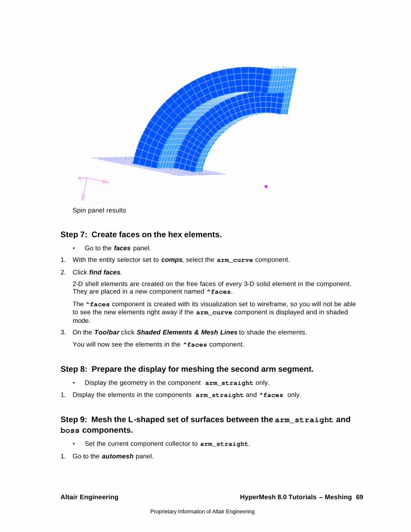
Altair Engineering HyperMesh 8.0 Tutorials – Meshing 69
Proprietary Information of Altair Engineering
Spin panel results
Step 7: Create faces on the hex elements.
• Go to the faces panel.
1. With the entity selector set to comps, select the arm_curve component.
2. Click find faces.
2-D shell elements are created on the free faces of every 3-D solid element in the component. They are placed in a new component named ^faces.
The ^faces component is created with its visualization set to wireframe, so you will not be able to see the new elements right away if the arm_curve component is displayed and in shaded mode.
3. On the Toolbar click Shaded Elements & Mesh Lines to shade the elements.
You will now see the elements in the ^faces component.
Step 8: Prepare the display for meshing the second arm segment.
• Display the geometry in the component arm_straight only.
1. Display the elements in the components arm_straight and ^faces only.
Step 9: Mesh the L-shaped set of surfaces between the arm_straight and boss components.
• Set the current component collector to arm_straight.
1. Go to the automesh panel.
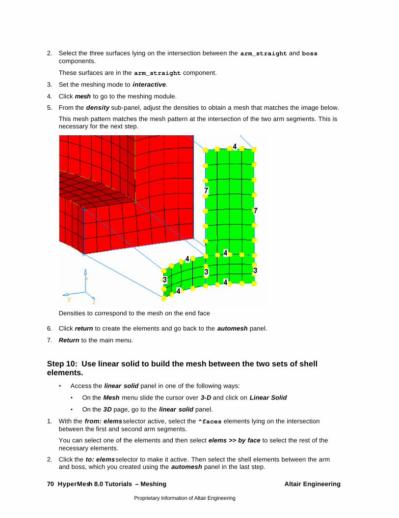
70 HyperMesh 8.0 Tutorials – Meshing Altair Engineering
Proprietary Information of Altair Engineering
2. Select the three surfaces lying on the intersection between the arm_straight and boss components.
These surfaces are in the arm_straight component.
3. Set the meshing mode to interactive.
4. Click mesh to go to the meshing module.
5. From the density sub-panel, adjust the densities to obtain a mesh that matches the image below.
This mesh pattern matches the mesh pattern at the intersection of the two arm segments. This is necessary for the next step.
Densities to correspond to the mesh on the end face
6. Click return to create the elements and go back to the automesh panel.
7. Return to the main menu.
Step 10: Use linear solid to build the mesh between the two sets of shell elements.
• Access the linear solid panel in one of the following ways:
• On the Mesh menu slide the cursor over 3-D and click on Linear Solid
• On the 3D page, go to the linear solid panel.
1. With the from: elems selector active, select the ^faces elements lying on the intersection between the first and second arm segments.
You can select one of the elements and then select elems >> by face to select the rest of the necessary elements.
2. Click the to: elems selector to make it active. Then select the shell elements between the arm and boss, which you created using the automesh panel in the last step.
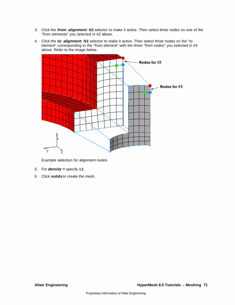
Altair Engineering HyperMesh 8.0 Tutorials – Meshing 71
Proprietary Information of Altair Engineering
3. Click the from: alignment: N1 selector to make it active. Then select three nodes on one of the "from elements" you selected in #2 above.
4. Click the to: alignment: N1 selector to make it active. Then select three nodes on the "to element" corresponding to the "from element" with the three "from nodes" you selected in #4 above. Refer to the image below.
Example selection for alignment nodes
5. For density = specify 12.
6. Click solids to create the mesh.
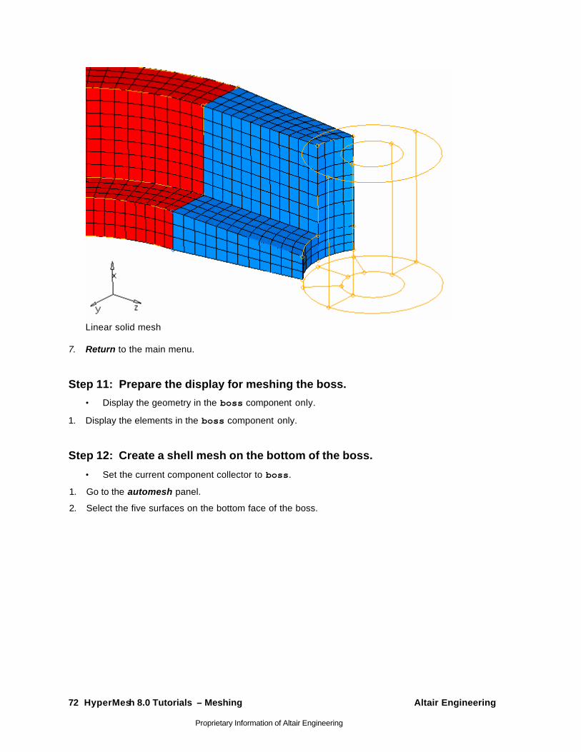
72 HyperMesh 8.0 Tutorials – Meshing Altair Engineering
Proprietary Information of Altair Engineering
Linear solid mesh
7. Return to the main menu.
Step 11: Prepare the display for meshing the boss.
• Display the geometry in the boss component only.
1. Display the elements in the boss component only.
Step 12: Create a shell mesh on the bottom of the boss.
• Set the current component collector to boss.
1. Go to the automesh panel.
2. Select the five surfaces on the bottom face of the boss.
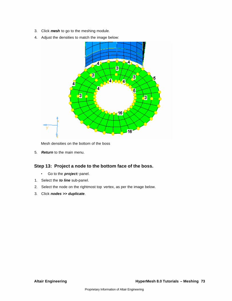
Altair Engineering HyperMesh 8.0 Tutorials – Meshing 73
Proprietary Information of Altair Engineering
3. Click mesh to go to the meshing module.
4. Adjust the densities to match the image below:
Mesh densities on the bottom of the boss
5. Return to the main menu.
Step 13: Project a node to the bottom face of the boss.
• Go to the project: panel.
1. Select the to line sub-panel.
2. Select the node on the rightmost top vertex, as per the image below.
3. Click nodes >> duplicate.
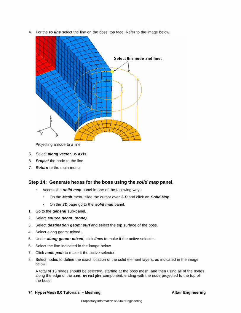
74 HyperMesh 8.0 Tutorials – Meshing Altair Engineering
Proprietary Information of Altair Engineering
4. For the to line select the line on the boss’ top face. Refer to the image below.
Projecting a node to a line
5. Select along vector: x- axis.
6. Project the node to the line.
7. Return to the main menu.
Step 14: Generate hexas for the boss using the solid map panel.
• Access the solid map panel in one of the following ways:
• On the Mesh menu slide the cursor over 3-D and click on Solid Map
• On the 3D page go to the solid map panel.
1. Go to the general sub-panel.
2. Select source geom: (none).
3. Select destination geom: surf and select the top surface of the boss.
4. Select along geom: mixed.
5. Under along geom: mixed, click lines to make it the active selector.
6. Select the line indicated in the image below.
7. Click node path to make it the active selector.
8. Select nodes to define the exact location of the solid element layers, as indicated in the image below.
A total of 13 nodes should be selected, starting at the boss mesh, and then using all of the nodes along the edge of the arm_straight component, ending with the node projected to the top of the boss.
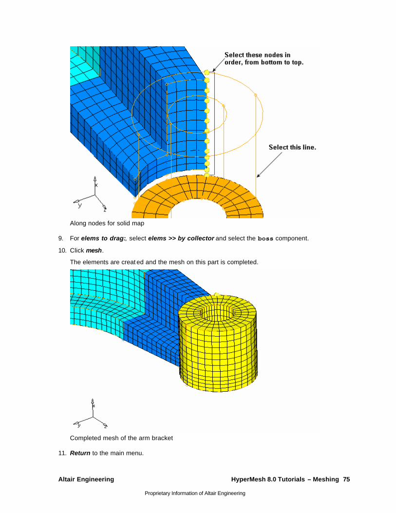
Altair Engineering HyperMesh 8.0 Tutorials – Meshing 75
Proprietary Information of Altair Engineering
Along nodes for solid map
9. For elems to drag:, select elems >> by collector and select the boss component.
10. Click mesh.
The elements are creat ed and the mesh on this part is completed.
Completed mesh of the arm bracket
11. Return to the main menu.
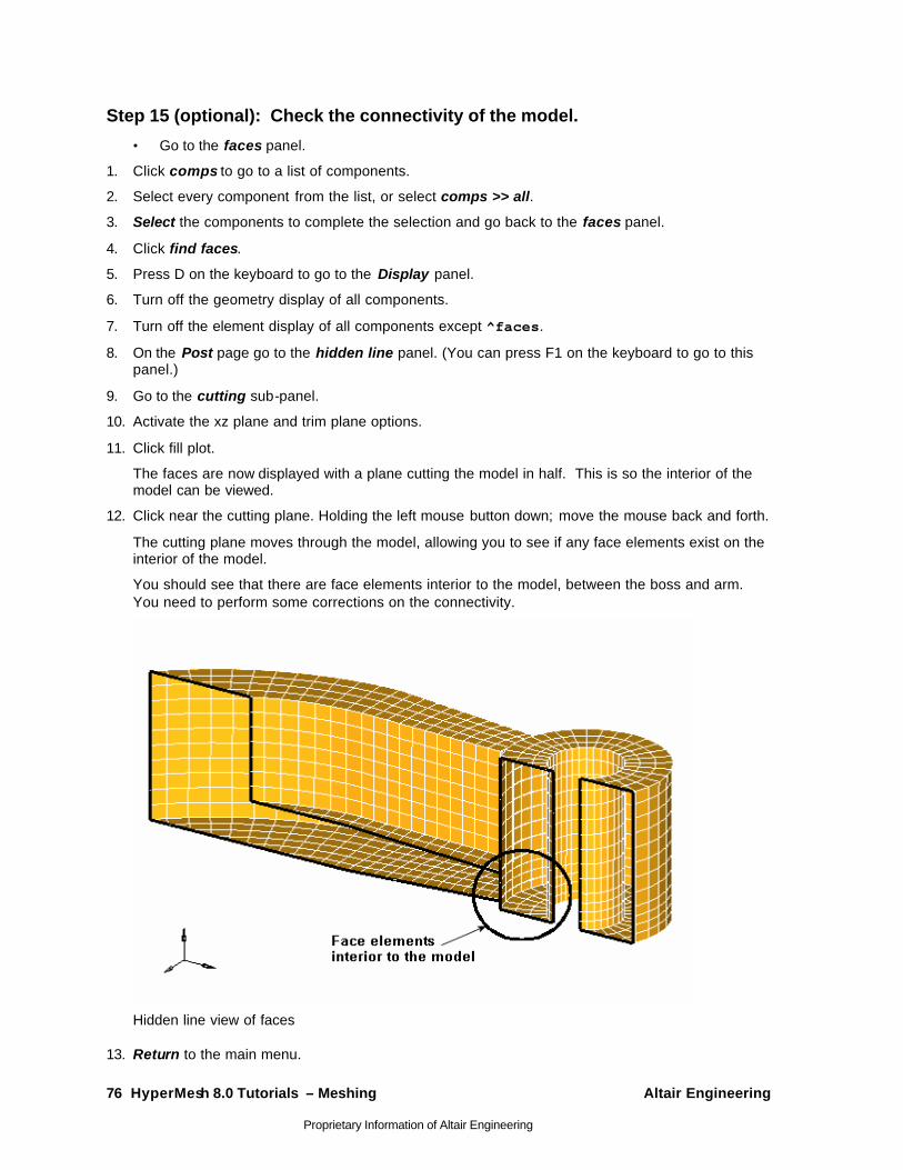
76 HyperMesh 8.0 Tutorials – Meshing Altair Engineering
Proprietary Information of Altair Engineering
Step 15 (optional): Check the connectivity of the model.
• Go to the faces panel.
1. Click comps to go to a list of components.
2. Select every component from the list, or select comps >> all.
3. Select the components to complete the selection and go back to the faces panel.
4. Click find faces.
5. Press D on the keyboard to go to the Display panel.
6. Turn off the geometry display of all components.
7. Turn off the element display of all components except ^faces.
8. On the Post page go to the hidden line panel. (You can press F1 on the keyboard to go to this panel.)
9. Go to the cutting sub-panel.
10. Activate the xz plane and trim plane options.
11. Click fill plot.
The faces are now displayed with a plane cutting the model in half. This is so the interior of the model can be viewed.
12. Click near the cutting plane. Holding the left mouse button down; move the mouse back and forth.
The cutting plane moves through the model, allowing you to see if any face elements exist on the interior of the model.
You should see that there are face elements interior to the model, between the boss and arm. You need to perform some corrections on the connectivity.
Hidden line view of faces
13. Return to the main menu.
Altair Engineering HyperMesh 8.0 Tutorials – Meshing 77
Proprietary Information of Altair Engineering
Step 16 (Optional): Correct the connectivity of the model.
• Display elements for all components except for the ^faces component.
1. Display the elements of the solidmap component as transparent.
2. Go to the faces panel.
3. Select elems >> displayed.
4. Click preview equiv.
Coincident nodes on the intersection between the arm and the boss are highlighted.
5. Specify a slightly larger value for tolerance =, and click preview equiv to identify more coincident nodes on the intersection.
6. Repeat #6 until all 60 coincident nodes have been found.
7. Click equivalence.
The nodes are replaced to the location of the lowest node ID.
8. Switch all the components to the shaded visual mode.
Step 17 (Optional): Recheck the connectivity of the model. Repeat Step 16 above to make sure the model is now equivalenced. If you find errors, repeat either Step 17 or Step 18 to correct the errors.
Step 18 (Optional): Save your work. The 3-D solid mesh has now been completed. Save the model if desired.
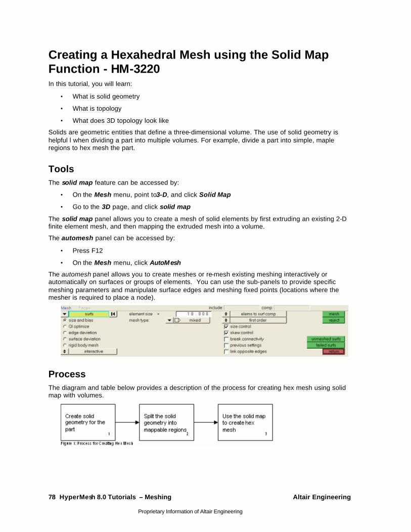
78 HyperMesh 8.0 Tutorials – Meshing Altair Engineering
Proprietary Information of Altair Engineering
Creating a Hexahedral Mesh using the Solid Map Function - HM-3220 In this tutorial, you will learn:
• What is solid geometry
• What is topology
• What does 3D topology look like
Solids are geometric entities that define a three-dimensional volume. The use of solid geometry is helpful l when dividing a part into multiple volumes. For example, divide a part into simple, maple regions to hex mesh the part.
Tools The solid map feature can be accessed by:
• On the Mesh menu, point to3-D, and click Solid Map
• Go to the 3D page, and click solid map
The solid map panel allows you to create a mesh of solid elements by first extruding an existing 2-D finite element mesh, and then mapping the extruded mesh into a volume.
The automesh panel can be accessed by:
• Press F12
• On the Mesh menu, click AutoMesh
The automesh panel allows you to create meshes or re-mesh existing meshing interactively or automatically on surfaces or groups of elements. You can use the sub-panels to provide specific meshing parameters and manipulate surface edges and meshing fixed points (locations where the mesher is required to place a node).
Process The diagram and table below provides a description of the process for creating hex mesh using solid map with volumes.
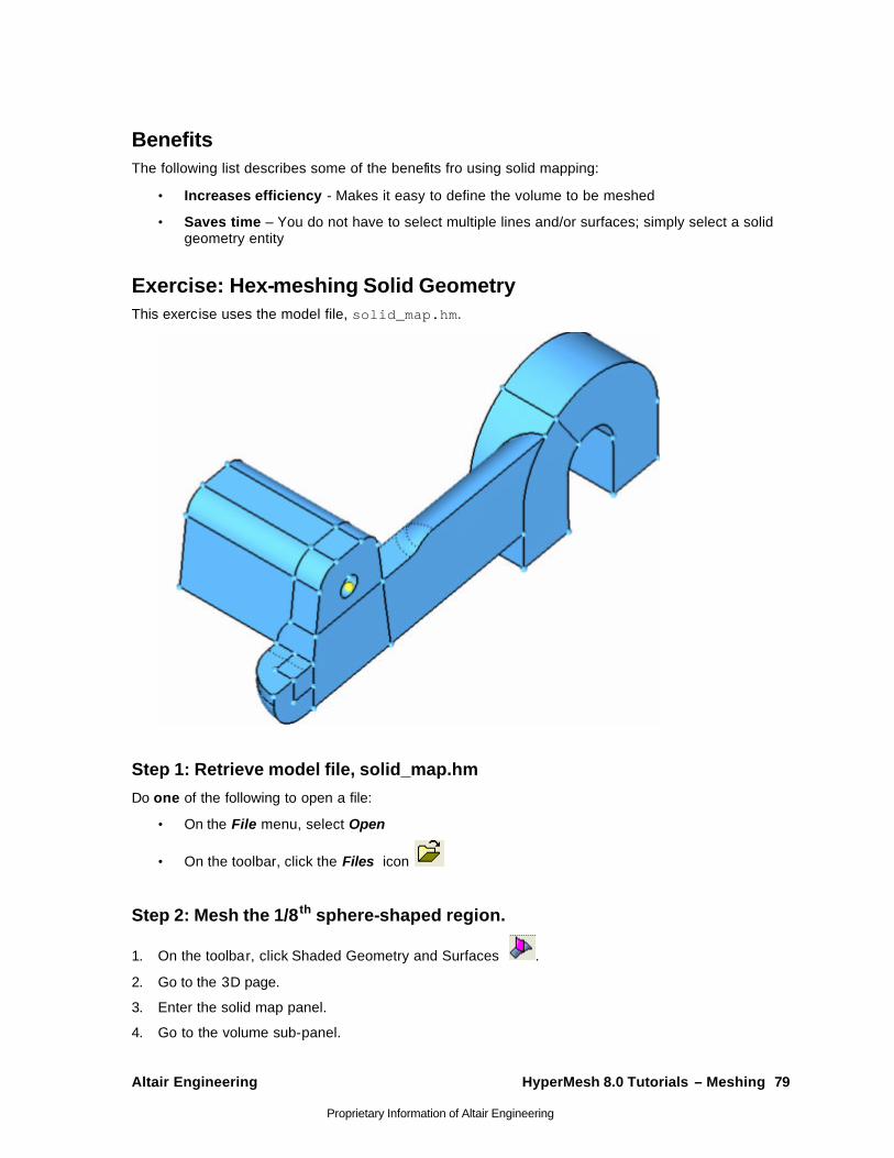
Altair Engineering HyperMesh 8.0 Tutorials – Meshing 79
Proprietary Information of Altair Engineering
Benefits The following list describes some of the benefits fro using solid mapping:
• Increases efficiency - Makes it easy to define the volume to be meshed
• Saves time – You do not have to select multiple lines and/or surfaces; simply select a solid geometry entity
Exercise: Hex-meshing Solid Geometry This exercise uses the model file, solid_map.hm.
Step 1: Retrieve model file, solid_map.hm
Do one of the following to open a file:
• On the File menu, select Open
• On the toolbar, click the Files icon
Step 2: Mesh the 1/8th sphere-shaped region.
1. On the toolbar, click Shaded Geometry and Surfaces .
2. Go to the 3D page.
3. Enter the solid map panel.
4. Go to the volume sub-panel.
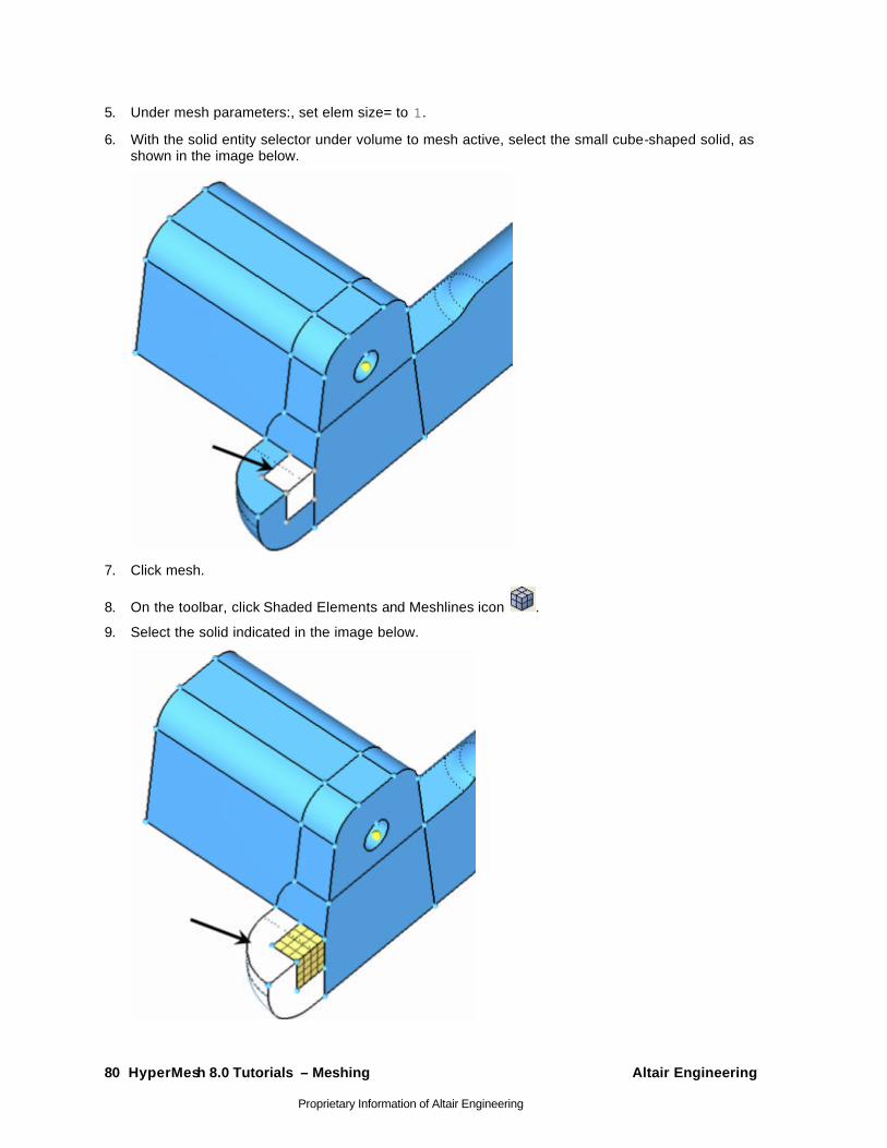
80 HyperMesh 8.0 Tutorials – Meshing Altair Engineering
Proprietary Information of Altair Engineering
5. Under mesh parameters:, set elem size= to 1.
6. With the solid entity selector under volume to mesh active, select the small cube-shaped solid, as shown in the image below.
7. Click mesh.
8. On the toolbar, click Shaded Elements and Meshlines icon .
9. Select the solid indicated in the image below.
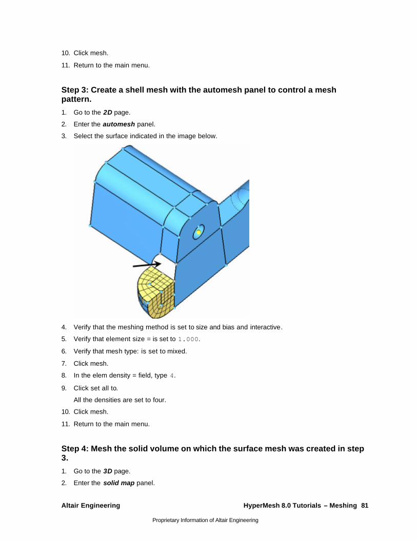
Altair Engineering HyperMesh 8.0 Tutorials – Meshing 81
Proprietary Information of Altair Engineering
10. Click mesh.
11. Return to the main menu.
Step 3: Create a shell mesh with the automesh panel to control a mesh pattern.
1. Go to the 2D page.
2. Enter the automesh panel.
3. Select the surface indicated in the image below.
4. Verify that the meshing method is set to size and bias and interactive.
5. Verify that element size = is set to 1.000.
6. Verify that mesh type: is set to mixed.
7. Click mesh.
8. In the elem density = field, type 4.
9. Click set all to.
All the densities are set to four.
10. Click mesh.
11. Return to the main menu.
Step 4: Mesh the solid volume on which the surface mesh was created in step 3.
1. Go to the 3D page.
2. Enter the solid map panel.
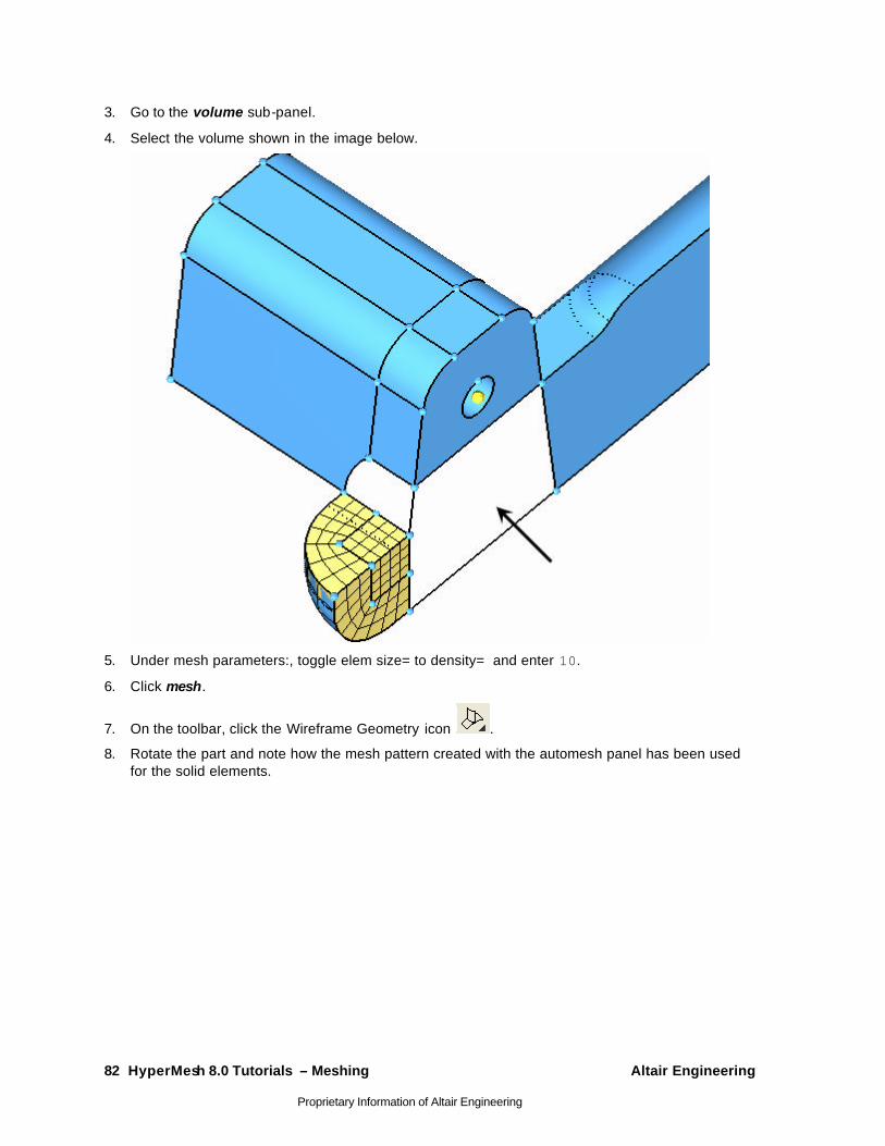
82 HyperMesh 8.0 Tutorials – Meshing Altair Engineering
Proprietary Information of Altair Engineering
3. Go to the volume sub-panel.
4. Select the volume shown in the image below.
5. Under mesh parameters:, toggle elem size= to density= and enter 10.
6. Click mesh.
7. On the toolbar, click the Wireframe Geometry icon .
8. Rotate the part and note how the mesh pattern created with the automesh panel has been used for the solid elements.
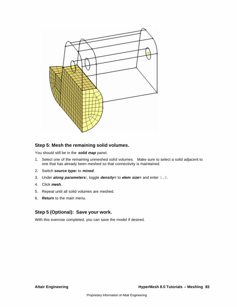
Altair Engineering HyperMesh 8.0 Tutorials – Meshing 83
Proprietary Information of Altair Engineering
Step 5: Mesh the remaining solid volumes.
You should still be in the solid map panel.
1. Select one of the remaining unmeshed solid volumes. Make sure to select a solid adjacent to one that has already been meshed so that connectivity is maintained.
2. Switch source type: to mixed.
3. Under along parameters:, toggle density= to elem size= and enter 1.5.
4. Click mesh.
5. Repeat until all solid volumes are meshed.
6. Return to the main menu.
Step 5 (Optional): Save your work.
With this exercise completed, you can save the model if desired.
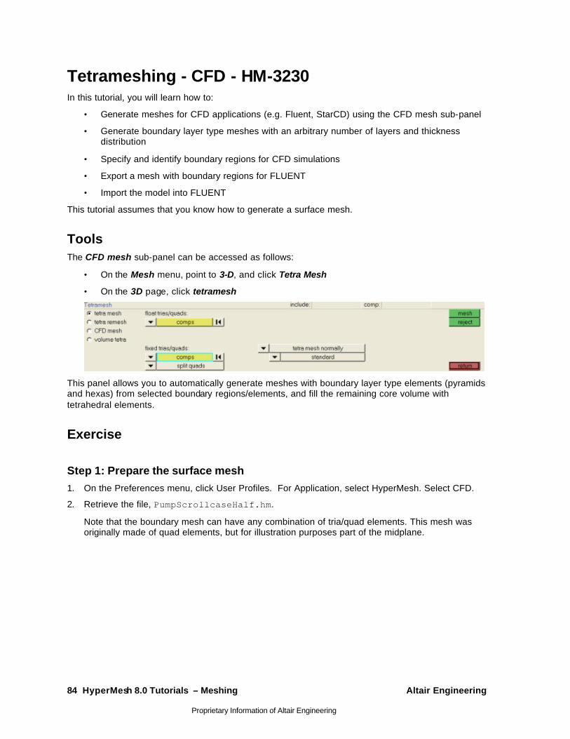
84 HyperMesh 8.0 Tutorials – Meshing Altair Engineering
Proprietary Information of Altair Engineering
Tetrameshing - CFD - HM-3230 In this tutorial, you will learn how to:
• Generate meshes for CFD applications (e.g. Fluent, StarCD) using the CFD mesh sub-panel
• Generate boundary layer type meshes with an arbitrary number of layers and thickness distribution
• Specify and identify boundary regions for CFD simulations
• Export a mesh with boundary regions for FLUENT
• Import the model into FLUENT
This tutorial assumes that you know how to generate a surface mesh.
Tools The CFD mesh sub-panel can be accessed as follows:
• On the Mesh menu, point to 3-D, and click Tetra Mesh
• On the 3D page, click tetramesh
This panel allows you to automatically generate meshes with boundary layer type elements (pyramids and hexas) from selected boundary regions/elements, and fill the remaining core volume with tetrahedral elements.
Exercise
Step 1: Prepare the surface mesh 1. On the Preferences menu, click User Profiles. For Application, select HyperMesh. Select CFD.
2. Retrieve the file, PumpScrollcaseHalf.hm.
Note that the boundary mesh can have any combination of tria/quad elements. This mesh was originally made of quad elements, but for illustration purposes part of the midplane.
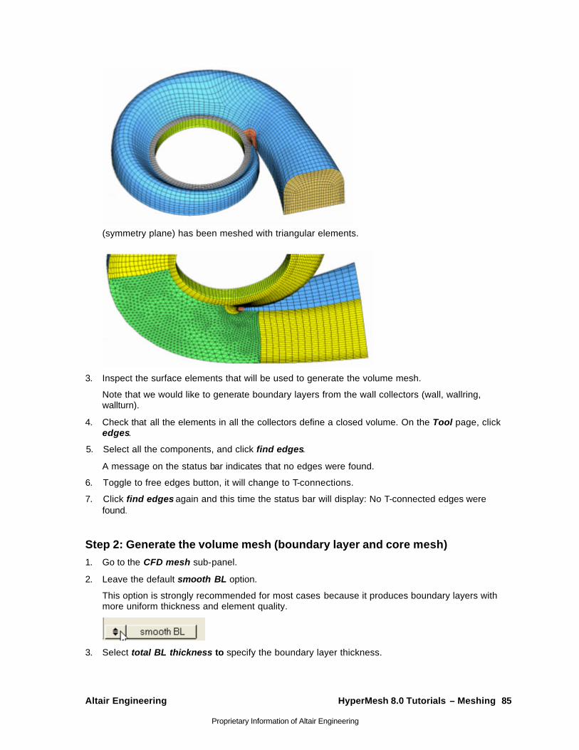
Altair Engineering HyperMesh 8.0 Tutorials – Meshing 85
Proprietary Information of Altair Engineering
(symmetry plane) has been meshed with triangular elements.
3. Inspect the surface elements that will be used to generate the volume mesh.
Note that we would like to generate boundary layers from the wall collectors (wall, wallring, wallturn).
4. Check that all the elements in all the collectors define a closed volume. On the Tool page, click edges.
5. Select all the components, and click find edges.
A message on the status bar indicates that no edges were found.
6. Toggle to free edges button, it will change to T-connections.
7. Click find edges again and this time the status bar will display: No T-connected edges were found.
Step 2: Generate the volume mesh (boundary layer and core mesh) 1. Go to the CFD mesh sub-panel.
2. Leave the default smooth BL option.
This option is strongly recommended for most cases because it produces boundary layers with more uniform thickness and element quality.
3. Select total BL thickness to specify the boundary layer thickness.
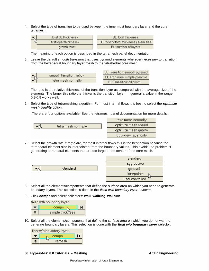
86 HyperMesh 8.0 Tutorials – Meshing Altair Engineering
Proprietary Information of Altair Engineering
4. Select the type of transition to be used between the innermost boundary layer and the core tetramesh.
The meaning of each option is described in the tetramesh panel documentation.
5. Leave the default smooth transition that uses pyramid elements wherever necessary to transition from the hexahedral boundary layer mesh to the tetrahedral core mesh.
The ratio is the relative thickness of the transition layer as compared with the average size of the elements. The larger this ratio the thicker is the transition layer. In general a value in the range 0.3-0.8 works well.
6. Select the type of tetrameshing algorithm. For most internal flows it is best to select the optimize mesh quality option.
There are four options available. See the tetramesh panel documentation for more details.
7. Select the growth rate interpolate, for most internal flows this is the best option because the tetrahedral element size is interpolated from the boundary values. This avoids the problem of generating tetrahedral elements that are too large at the center of the core mesh.
8. Select all the elements/components that define the surface area on which you need to generate boundary layers. This selection is done in the fixed with boundary layer selector.
9. Click comps and select collectors: wall, wallring, wallturn.
10. Select all the elements/components that define the surface area on which you do not want to generate boundary layers. This selection is done with the float w/o boundary layer selector.
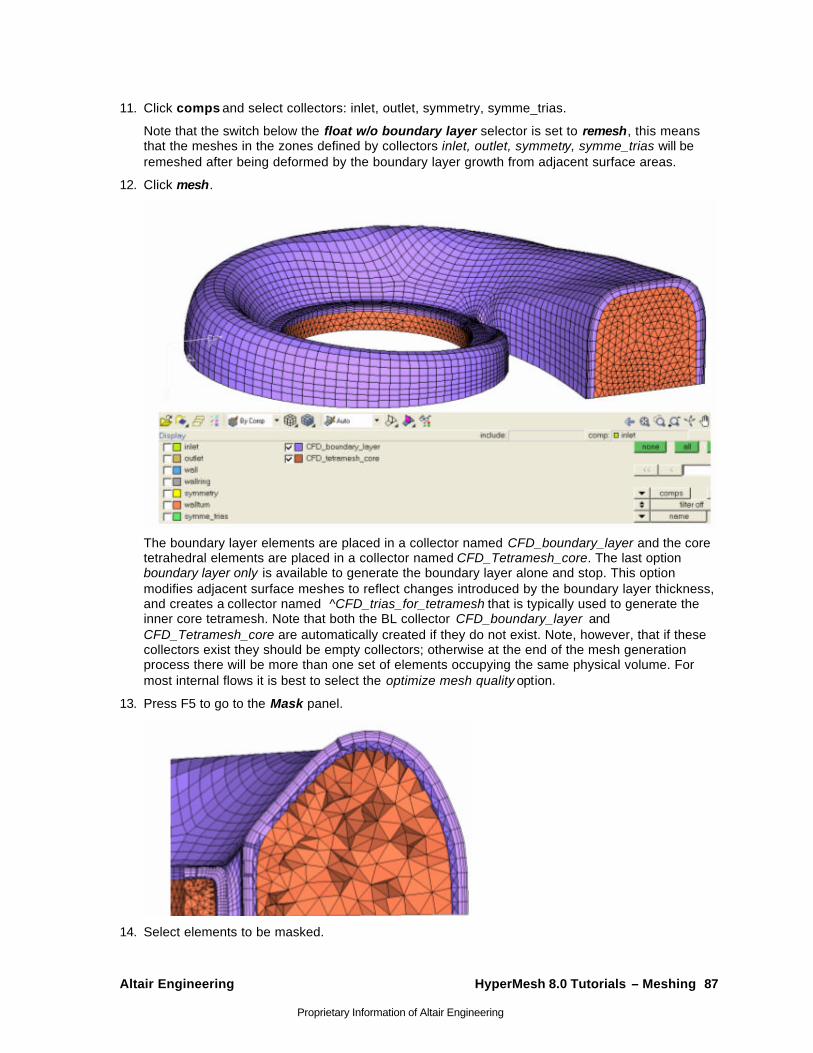
Altair Engineering HyperMesh 8.0 Tutorials – Meshing 87
Proprietary Information of Altair Engineering
11. Click comps and select collectors: inlet, outlet, symmetry, symme_trias.
Note that the switch below the float w/o boundary layer selector is set to remesh, this means that the meshes in the zones defined by collectors inlet, outlet, symmetry, symme_trias will be remeshed after being deformed by the boundary layer growth from adjacent surface areas.
12. Click mesh.
The boundary layer elements are placed in a collector named CFD_boundary_layer and the core tetrahedral elements are placed in a collector named CFD_Tetramesh_core. The last option boundary layer only is available to generate the boundary layer alone and stop. This option modifies adjacent surface meshes to reflect changes introduced by the boundary layer thickness, and creates a collector named ^CFD_trias_for_tetramesh that is typically used to generate the inner core tetramesh. Note that both the BL collector CFD_boundary_layer and CFD_Tetramesh_core are automatically created if they do not exist. Note, however, that if these collectors exist they should be empty collectors; otherwise at the end of the mesh generation process there will be more than one set of elements occupying the same physical volume. For most internal flows it is best to select the optimize mesh quality option.
13. Press F5 to go to the Mask panel.
14. Select elements to be masked.
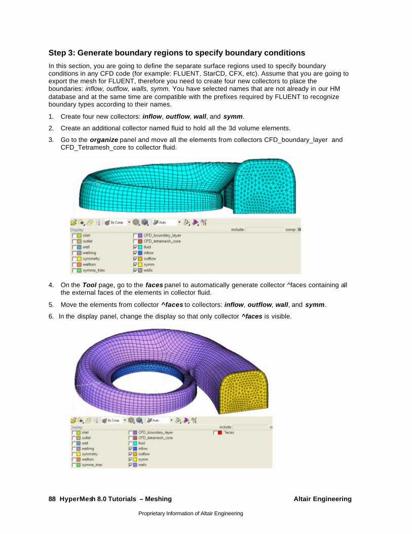
88 HyperMesh 8.0 Tutorials – Meshing Altair Engineering
Proprietary Information of Altair Engineering
Step 3: Generate boundary regions to specify boundary conditions
In this section, you are going to define the separate surface regions used to specify boundary conditions in any CFD code (for example: FLUENT, StarCD, CFX, etc). Assume that you are going to export the mesh for FLUENT, therefore you need to create four new collectors to place the boundaries: inflow, outflow, walls, symm. You have selected names that are not already in our HM database and at the same time are compatible with the prefixes required by FLUENT to recognize boundary types according to their names.
1. Create four new collectors: inflow, outflow, wall, and symm.
2. Create an additional collector named fluid to hold all the 3d volume elements.
3. Go to the organize panel and move all the elements from collectors CFD_boundary_layer and CFD_Tetramesh_core to collector fluid.
4. On the Tool page, go to the faces panel to automatically generate collector ^faces containing all the external faces of the elements in collector fluid.
5. Move the elements from collector ^faces to collectors: inflow, outflow, wall, and symm.
6. In the display panel, change the display so that only collector ^faces is visible.
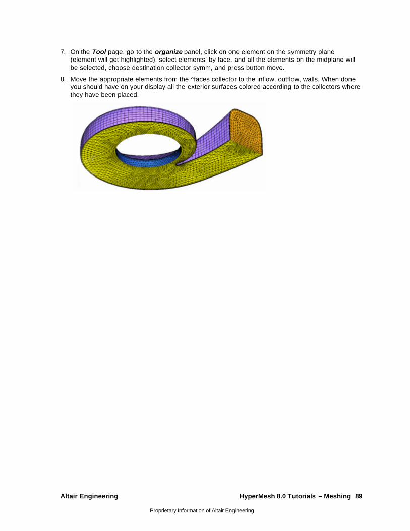
Altair Engineering HyperMesh 8.0 Tutorials – Meshing 89
Proprietary Information of Altair Engineering
7. On the Tool page, go to the organize panel, click on one element on the symmetry plane (element will get highlighted), select elements’ by face, and all the elements on the midplane will be selected, choose destination collector symm, and press button move.
8. Move the appropriate elements from the ^faces collector to the inflow, outflow, walls. When done you should have on your display all the exterior surfaces colored according to the collectors where they have been placed.