HYPERBOLIC..(U) STANFORD llllfl.flflllll IEEIIIIE*E*EEE El ... · / muI.I-ffflllflflf//llff.26. II...
88
RD-R148 059 GENERATION OF THREE DIMENSIONAL BODY FITTED COORDINATES 1/1 USING HYPERBOLIC..(U) STANFORD UNIY CA DEPT OF AERONAUTICS AND ASTRONAUTICS J L STEGER MAR 94 UNCLASSIFIED FOSR-TR-84-1022 RFOSR- 82-0254 F/G 20/4 NL llllfl.flflllll IEEIIIIE*E*EEE El//I/l/llmlllu I IlhElhhlhhElh / ffflllflflf//llff muI.I-
Transcript of HYPERBOLIC..(U) STANFORD llllfl.flflllll IEEIIIIE*E*EEE El ... · / muI.I-ffflllflflf//llff.26. II...

RD-R148 059 GENERATION OF THREE DIMENSIONAL BODY FITTED COORDINATES 1/1USING HYPERBOLIC..(U) STANFORD UNIY CA DEPT OFAERONAUTICS AND ASTRONAUTICS J L STEGER MAR 94
UNCLASSIFIED FOSR-TR-84-1022 RFOSR- 82-0254 F/G 20/4 NL
llllfl.flflllllIEEIIIIE*E*EEEEl//I/l/llmlllu
I IlhElhhlhhElh/ ffflllflflf//llffmuI.I-

6. .2
II I * 21& 1W6 -
1111.25 i 41111
1 N... 11.6
MICROCOPY RESOLUTION TEST C4ART
NATIONAL iWU AU %TAW&AoS-Iq63-A
* * . - *- r° • * " . . * . . . . . . . . . . . . . . . *
' "* .% * "
" " "
" " "
% * ° . -. - . .'
to~-
°-w . . . w.. . ..- - °.... . . . ...... .o ... .. .°. -.. ... ..... . .. . .. . .

SECURITY CLASSIFICATION OF THIS PAGE I
REPORT DOCIJMFNTATIOI' PAGE
2a. SECURITY CI.ASSIFIC 1 8 0 9 DIST RIBUT ION/ AVAILABILITY OF REPORT
2b DECLASSIFICATION o
1. PERFORMING ORGANIZATION REPORT NUMBER(S) S. MON17ORING ORGANIZATION REPORT NUMBER(S)0
AFOSift-Th., 84-10226a NAME OF PERFORMING ORGANIZATION 6bOFC YMBOL 7a. NAME OF MONITORING ORGANIZATIONDepartment of Aeronautics & Ast onafttffi861) A RNStanford UniverstAORN
6c_ ADDRESS (City, Stotand ZIP Code) 7b. ADDRESS (City, State, and ZIP Code)
Si. NAME OF FUNDING ISPONSORING Sb. OFFICE SYMBOL 9. PROCUREMENT INSTRUMENT IDENTIFICATION NUMBERORGANIZATION AOR(if applicable) AFOSR-82-02 54
AFOSR NA
Sc. ADDRESS (City, Staff, and ZIP Code) 10 SOURCE OF FUNDING NUMBERSPROGRAM IPROJECT TASK IWORK UNIT
Building 410 ELEMENT NO. NO. NO. ~ ACCESSION NO.Bolling AFB, DC 20332 161102F I
11. TITLE (Include Security Classification)Generation of Three Dimensional Body Fitted Coordinates Using Hyperbolic PartialDifferential Equations
12. PERSONAL AUTHOR(S)Joseph L. Steger
13a. TYPE OF REPORT 123b TIME COVERED 14. DATE OF REPORT (Year, Month. Day) 5 PAGE COUNTFINAL FROM TO March 1984-
16. SUPPLEMENTARY NOTATION-
17. COSATI CODES j18 SUBJECT TERMS (Continue on reverse if necessary and identify by block number)FIELD GROUP SUB-GROUP
19 ABSTRACT (Continue on rev'erse if necessary and identify by block number)
See back
DTICteDNOY 2Ba1984
20. DISTRIBUTION /AVAILABILITY OF ABSTRACT 21. ABSTRACT SECURITY CLASSIFICATIONLJUNCLASSIFIED/UNLIMITED 0 SAME AS RPT. DTIC USERS
22a NAME OF RESPONSIBLE INDIVIDUAL 22b TELEPHONE (include Area Code) 22c OFFICE SYMBOLDR JAMES WILSON (22 6-95NA
Do FORM 1473,84 MAR 83 APR edition may be used until exhausted SECURITY CLASSIFICATION OF THIS PAGAll other editions are obsoleto
84 ii26 2334-- 1 --. *. - . . - ..8 4" - .

. . . . .• . . . .. . "
I[GuRITY'l CL - aa : r C A T IO
Nl
OF TI, .| . l.
/ The purpose of this research has been to further develop a simple efficient gridgeneration procedure for external aerodynamics aplication. The grid generationscheme is based on solving hyperbolic partial differential equation constraints of gridangularity and mesh incremental volumes. The grid generation scheme has been
previously used in two dimensional applications to generate grids about smooth
body shapes. The main thrust of this AFOSR supported research has been to
extend the hyperbolic partial differential equation procedure to three dimensionalapplications and to study ways of applying the procedure to body shapes that have
discontinuous derivatives.The main part of this report, Part I, is devoted to describing the three dimensional
hyperbolic grid generator. This Section first reviews the hyperbolic grid generation
procedure in two dimensions and then describes the extension to three dimensions.1The numerical solution algorithm, mesh control functions and treatment of axi
singularities are then described. Computed meshes od.even are calculated flowfled result are shown tohelpe.luete-hegrids.Part I of this report is essentially
. a sell-contlned technical report that is being readied for submission to a Journal.
4-Part II of this report is both brief and sketchy in its presentation. In this section
we describe some of our success in treating bodies with sharp edges and bodies
that are exceptionally concave. The hyperbolic grid generation tends to propogate
discontinuities and some bodieslare not compatible with the imposed orthogonality
and volume constraints that at user imposed. When this happens, the hyperbolic
grid generator breaks dow What must be done in this case is to relax these
constraints. We some success doing this, but this process remains still an
. artfam-' /The last part of this report describes a flow field algorithm development. During -
the course of this research we had some considerable interaction with AFWAL,
and at one point became 'side-tracked' into a successful approach of improving the
efficiency of our general implicit Euler aad Navier-Stokes code. art I of this
" paper contains a preliminary paper describing this development.
Accession For?RTIS GRA&IDTIC TAB 0Unannounced [Just ificatio _
:'.'- By.""' Distribution/
Availability Codes
!Avail and/orDlt Special
IA_
- ," " SCCURITY CLASSItICAlTO14 OF T14t1 P&
~. ............. :. ..... ....... . . . .. .

XFOSR-TR- 8 4 102 2
USING YPERLICNPRALIO OF
THREE DIESOA OYFITTED COORDINATES
USIN HYERBLICPARIALDIFFERENTIAL EQUATIONS
Joseph L. Steger
Department of Aeronautics and Astronautics
Stanford University
Stanford, California 94305
March 1984Final Report for Grant AFOSR-82-0254
Ppproved for p*- r3 e~
84 11 26 233
. ~~.. . . .

I ' ' -..-..-
FOREWORD
The purpose of this research has been to further develop a simple efficient gridgeneration procedure for external aerodynamics aplications. The grid generationscheme is based on solving hyperbolic partial differential equation constraints of gridangularity and mesh incremental volumes. The grid generation scheme has beenpreviously used in two dimensional applications to generate grids about smoothbody shapes. The main thrust of this AFOSR supported research has been toextend the hyperbolic partial differential equation procedure to three dimensionalapplications and to study ways of applying the procedure to body shapes that havediscontinuous derivatives.
The main part of this report, Part I, is devoted to describing the three dimensionalhyperbolic grid generator. This Section first reviews the hyperbolic grid generationprocedure in two dimensions and then describes the extension to three dimensions.The numerical solution algorithm, mesh control functions and treatment of axissingularities are then described. Computed meshes and even are calculated flowfled result are shown to help evaluate the grids. Part I of this report is essentiallya self contained technical report that is being readied for submission to a Journal.
Part II of this report is both brief and sketchy in its presentation. In this sectionwe describe some of our success in treating bodies with sharp edges and bodiesthat are exceptionally concave. The hyperbolic grid generation tends to propogatediscontinuities and some bodies are not compatible with the imposed orthogonalityand volume constraints that are user imposed. When this happens, the hyperbolicgrid generator breaks down. What must be done in this case is to relax theseconstraints. We have had some success doing this, but this process remains still anart form.
The last part of this report describes a flow field algorithm development. Duringthe course of this research we had some considerable interaction with AFWAL,and at one point became 'side-tracked' into a successful approach of improving theefficiency of our general implicit Euler and Navier-Stokes code. Part Mf of thispaper contains a preliminary paper describing this development.
"'R FORCE @VTCE OP Y S CENTTFTC RnSrLjc j (ASC).
p , ". . . .. 'nd is
-9t:Chef, re ical Ifformat1oaD1,l. 1si
2'
:-.--..- :. ...,.-.-..-.-.-,.. ....... .... .-................ . . . . . . ....... .... * % • . . .. . . .. . :. ., ... .. .. .. .-.... .... ",,

[ . .-I - . -, .
PART I. GENERATION OFTHREE DIMENSIONAL BODY FITTED COORDINATES
USING HYPERBOLIC PARTIAL DIFFERENTIAL EQUATIONS
INTRODUCTIONBody conforming curvilinear grids are often used in finite difference flow field
simulations. One reason for this is that the application of boundary conditionscan be simplified in finite difference calculations because grid lines coincide with
boundary lines. This is especially important in high Reynolds number viscous flowsimulation in which high flow gradients near the body surface must be resolved.
The task of generating a satisfactory body conforming coordinate system is noteasy. The grids must not be too distorted, they should have smooth variation,and they should be clustered to flow field action regions - typically near boundarysurfaces. Moreover, the grids should be generated in an automatic manner thatrequires a minimum of user input.
One approach for generating body conforming grids with minimum user inputhas been to solve a set of partial differential equations. In this technique level linesof f(z, y, z), ii(z, y, z), and t(z, y, z) that have monotone variation are sought as asolution of a set of partial differential equations. Generally values of q, rg and Care user specified on the boundary surface and constraints expressed as differentialequations are used to develop the grid away from the boundaries. The most pop-ular such approach requires the solution of a set of elliptic equations that satisfythe maximum principle 11-51, however, hyperbolic [6,71 and parabolic [81 governingequations have been used as well, at least in two dimensional applications.
In this report one way of extending the hyperbolic grid generation method of
Steger and Chaussee [6] to three dimensions is developed. In two dimensions thetwo differential constraints
(Xqz + ~gy((Ia))
- = (AV)' ((ib))
or in C, q computational space
-ezq + yJie 0 ((2a))
X(Y', - X'jI( A V ((2b))
have been solved by marching in q from an initial data plane 9 (z, y) - constant.The first equation is a constraint of orthogonality. The second equation controlsthe mesh spacing with the user specifying the mesh control volume AV (actuallyarea in two dimensions). A linearized version of equations (2) is readily shown to be
N . . . ... . ..

hyperbolic and suitable for marching in '1. Equations (2) are solved in computationalspace to give the z, y location of the constant and , = constant grid lines.
The two partial differential equations, expressed as either Equations (1) or Equa-tions (2), have been referred to as a mesh cell volume procedure for grid generation.In the next section a three dimensional extension of this procedure is developed.
THREE DIMENSIONAL GRID GENERATION EQUATIONS
A body fitted exterior grid about an arbitrary closed boundary surface is desired.Only a simple topology such as that illustrated in Figure (1) will be consideredhere. The body surface is chosen to coincide with (z, Y, z) = 0 and the surfacegrid line distributions of - constant and q = constant are user specified. Theouter boundary (z, V, z) = 'maz is not specified, it is only required to be sufficientlyfar removed from the inner boundary. Using f as the marching direction, partialdifferential equations are sought which produce planes of constant f, i/ and toform a nonsingular mesh system.
An extension of the mesh cell volume procedure to three dimensions is proposed.In three dimensions, however, there are three orthogonality relations and one cellvolume constraint. At any point four equations are available to predict the threeunknowns z, V and z so one equation must be discarded. Because C is the marchingdirection it is natural to use only the two orthogonality relations that involve C, thisleads to the governing equations
wCx-f+ yo + zfzt = 0 ((3a))
X"-'t + iUc + z.rZ = 0 ((3b))
z L41 Zt + z4f z it + zV -9 Cz C1 Zil - qfzgUZ f Z f IZe A ((3c))
or with F defined as (z, V, z)'
e -. =o, 4, C 0, ,AV
The first two equations represent orthogonality relations between and f and be-tween 9 and C, while the last equation is the volume or finite Jacobian constraint.
Equations (3) comprise a system of nonlinear partial differential equations inwhich z,y and z are specified as initial data at f = 0. As developed below, lin-earization and analysis of Equations (3) about a nearby known state reveals thatthe system is hyperbolic with r as the marching direction.
Let z, Y0 , z° represent a nearby known state so that
2 = ° + (z - z°) =z ° +
1=0+
0Z=z +i
2
"" * * 2~*~ i . -' * *

where 2, and i are small. Substitution of these expressions into Equations (3) and
elimination of products of tilde terms results in the locally linearized system
Ao(- o), + Bo(- fo),, + Co(F- o), = f ((5))
with
A=0 0 0 ((6a))
B = (zC . ) 1((6b))
(Yc z -Y(z) (x-z( - Zzez) (XcV, - --f )
= or oe I- -. . =0 ((6dl)):-Z (AV -AV AV - AVo
Letf R 9- F, then (5) is rewritten as
A4 + B j,, +c0 , = if ((7))
Now Co1 exists unless (AV)- -- oo, which we will not impose, so (7) can berewritten as
C-'AoA + C' o + , = C' (())Although the verification is nontrivial, Co'Ao and Co'Bo are found to be symmet-tic matrices (this was carried out by Dennis Jesperson of the NASA Ames ResearchCenter, who used MACSYMA). The linearized system Equation (8) is therefore
hyperbolic and can be marched with serving as the "time-like" direction.It can be pointed out that an analysis was attempted for the three orthogonality
relations alone. These equations, however, are found to be improperly posed formarching with initial data in r. Indeed, as best as we can discern, the three rela-tions do not lend themselves to unique solutions regardless of the type of boundaryconditions specified.
3
-'. 9 .* ******.

SOLUTION PROCEDUREThe nonlinear system of grid generation equations given by Equations (3) are .
solved with a noniterative implicit finite difference scheme. An unconditionallystable implicit scheme is chosen so the marching step size in C can be arbitrarilyselected based only on considerations of accurately generating the grid. Iterativesolution of the nonlinear grid generation equations is avoided by expanding theequations about the previous marching step. As a consequence Equation (7) is 0.solved with the nearby known state 0 taken from the previous C step.a) Numerical Method
Let I= Aq A = suchthat f=j-1,rq =k-1 and =l-1. Centralspatial differencing of Equations (5) in and q with first order backward implicitdifferencing in f leads to
Aj6c(Fi+zj -F) +E,5s,(Fi. 1 - iF) + CLV(ji+ A+di,(9)
where0S
andF 12 'j1F+ 2 1I
V1F1+1- o..., F
Note that C6aii was subtracted from A+t to produce ji+1 in the above. Throughoutonly those indices that change are indicated, thus r1+1 =P rj,kj+i, r+l :+j,etc.
Multiplying through by C0"j gives
Cr'A45e(1+i - A) + CTIBOV(4+ - F) + [(Fl+i F f)= '+ ((10))
where I is the identifying matrix. lb reduce the inversion cost the difference equa-tions are approximately factored as
(I + C'A6) + C'LAVFj - F= CT'&+,
so that F+t is obtained by solving sequences of one-dimensional-like block tridiag- -031 systems
(r + C'A a )#a+i =#I+, ((12a))
(I+Or 15)Vf Fi+L 4+ ((12b)) I
* . -. -.

F8 + V(FI+, ((12c))
In practise numerical dissipation terms are added in the and q directions. Typi-cally we have used a combination of fourth and second differences which are explic-itly and implicitly included into the basic algorithm as
11 + C- 1 Aj6t - e,(AV)eJI + Cr-'B1 6,1 - ej(AV)j](i + - i) =
ci-' d+,- + v)+
where e, is order - and ei is 2.5 or more larger than e.. As an alternative to fourthdifferences, second order terms such as
eAVr'IA
have been used both implicitly and explicitly.The coefficient matrices A1, B1 and C1 contain and q derivatives which are
IL formed using central differences. These matrices also contain derivatives for Zx, y"and z, which are obtained from Equations (3) in terms of f and 9 derivatives. Thatis, Equations (3) are linear in the unknowns xf, yC and z.. They are easily solvedfor as
(Dc e)( IbZ( ((13)= (D. ,,,e- , 1e,,(3)
withwDS(C) = (Y~:,-V ' + (,VZe - Z( Z,)' + (Za, -,
Note that AV//(zc + uf + q) - Det(C) so that Det(C) will be zero if and only
if the user specified AV = 0. Hence, 0 -C will exist.b) Cell Volume Specification
The user has control of the grid by means of the initial surface point distributionand by specification of the cell volumes, AVj,,j. Through the cell volumes theextent and clustering of the grid can be essentially controlled. Because the cellvolume at each point must be specified, it is clear that the user must devise somekind of method for determining volumes. There are many possibilities, here onesuch approach is illustrated.
Suppose we had & sphere to grid. A reasonable grid might have uniform anglespacing and have a radial grid distribution that is exponential. For this specialgeometry and grid we can analytically determine the control volumes by a simpleformula. Now take the problem at hand, perhaps an aircraft fuselage, which wewant to mesh as a warped spherical-like grid. We can find a sphere that has thesame surface area as our fuselage and use the grid cell volumes of the sphere to
; .
p. - . % . . . ....-.
".-'..-".: ..- . .......... . ,.._........-. .... .......... .- .....~ ..... * ...... .

specify the cell volumes of the fuselage grid. However, the fuselage will not havethe same kind of surface area distribution as a sphere with equal angle distribution.So here we need an adjustment, something like
= r i'~~,kiephere (1)Aia (Av'j,)SPjaeie 1-6) + IA .A(AAjk)fi wattage
where 6 - I for small 1 and 6 -- 0 for large 1. That is, the volumes would be*" adjusted initially to the local boundary surface increments. But as we march out
the uniform spherical volumes would gradually be specified. Such an approach hasbeen used, and, as a result, the far field portion of the grid tends to be uniformlyspherical. The results shown later will illustrate this behavior.
C) Axis TREATMENT
A coordinate singularity will be encountered whenever a regular grid is mappedover a closed body such that C - 0 corresponds to the body surface. Here wewill generate warped spherical grids, so equation (5) becomes singular at the axis.Using C as the marching direction with 4 and ri as sketched in Fig.2 (i.e. f frompole to pole and 9 equatorial ) then the axis at = 0 and = 6 representsingularities. In particular, 9 derivatives approach zero at the pole and equations(2b) and (2c) are lost. If there are KMAX points in the 9-direction, however, thedifference equation corresponding to Eq.(2a) can be imposed KMAX times to solvefor three axis unknowns, namely x,y, and z. Thus the axis points are overdeterminedand can be solved for via a generalized inverse scheme. Such an approach has beencoded. However, it is difficult to implement implicitly, and it has not proved to bereliable for severely distorded axis cases, for example, when the axis extends from .-
a wing tip.Rather than try to compute the axis as the solution evolves, we have instead
prespecified the axis position. For now a fixed straight axis has been used that isaligned with a coordinate. Typically a y-coordinate line has been chosen so that xand z are zero along the axis. Values of y along the axis are obtained as part of thesolution process by imposing the orthogonality conditon, which in this degeneratecame is simply aq, = 0. This condition is imposed using second order accurate threepoint difrerencing, and it is implicitly implemented into the q-block tridiagonal
solution process using a slightly modified block solver.
RESULTS
To demonstrate the hyperbolic grid solver a series of grids were generated aboutellipsoidal and 'super ellipsoidal' body shapes. The body generating function isgiven by
planform(X/,M..)" + (/Yr.s)" = 1"
• ". .'.

thickneo"
(U m + (t/ 3 )=
profile
(-/Xmas)' + (Z/Zm.1' = 1where n, m and I are 2 for ellipsoids and 4 or 6 or 8 etc. for super ellipsoids. Bychosing very high aspect ratios the ellipsoid can minick a practical wing planform,or, for more moderate aspect ratios, a fuselage. In either case an axis singularityexists.
The right half of an elliptic wing planform with the user specified body surfacegrid point distribution is shown in Fig.2. This 'wing' has a 16:1 planform aspectratio with a 20 per cent thick ellipse serving as the airfol. Thus the body is anellipsoid with ratios 16 : I : 1/5. A uniform grid spacing of 1/2 per cent thickmaximum chord was specified as the first grid spacing off the body. Figures.4 to 6show various segments of the generated grid for e and q = constant planes. Figure4 shows an q =constant plane ( here in the plane of the wing trailing edge) at thewing tip. As seen, the grid is very smooth, uniform off the body, and the axis atx = 0 is well behaved. A lower half of the grid at the wing midspan ( y = 0) is shownin Fig. 5. This is a f = constant plane. Again the smoothness and grid clusteringcontrol is illustrated. Also in the far field the grid is tending to be spherical becausespherical mesh incremental volumes have been specified. Finally, views above thewing in the z = 0 plane are shown in Figs. 6a and 6b. These views are focused atthe wing tip and again illustrate satisfactory axis treatment.
A similar grid was computed as illustrated by Figs. 7 to 10. The wing in thiscase used a more realistic airfoil shape that has a thickness ratio of 15 per cent.The grid views Figs. 7 and 9 give an indication of the wing and airfoil section. Notethat the airfoil has a rounded trailing edge.
It must be remarked that if the airfoil trailing edge radius is continuously reducedthat the method breaks down. "Pretty bows" get tied within the grid. Providedthe trailing edge radius is not zero, break down can usually be avoided by clusteringgrid points in this region and adjusting the specified volumes. In lieu of good surfaceclustering functions one can sometimes obtain an adequately resolved trailing edgeby generating an overall much finer grid than what is desired for the flow solver.In this case we simply discard, say, every other grid point to obtain the final grid.Because the hyperbolic grid solver is quite efficient, we can readily operate in thismanner. Ultimately the scheme does break down when subject to a truely sharptrailing edge.
The above grids have grid spacing that is adequate for inviscid low simulations.The hyperbolic grid generation procedure can also directly generate grids suitablefor high Reynolds number viscous low simulation by simply having the user specifya much finer mesh spacing going out away from the surface. In Figs. 11 and 14 we
7
, •.' ".%..........."................ . . '...*.'..."- ..... '.-.'.'...". .. .._." ,.._..: ,. ,...+_..". _...,.'. .. 2 . +. .,.+- +.'.,_.,-.,."*_ **_*_ *.**.*.*., ***..*,.* . .' . . .. *..,*.... .. ._'._'...... . ... ,.:

show views of a grid generated about a bluff body fuslage. The body in this caseis defined as a 2: 1 ellipsoid in the x-y and y-z planes ( see Fig. 11). In the x-zplane a 1: 1 super ellipsoidal cross section in specified by seting m = 4 ( see Fig.14). The first grid spacing off the body in this case was specified as 0.00002 of thebody cross sectional diameter. Magnified grid lines coming into the axis are shownin Fig. 13 to indicate this fine grid spacing just off the body.
Although a less interesting configuration, a similar viscous grid was generatedabout a 6: 1 : I ellipsoid. To demonstrate that the grids being generated with thisapproach are indeed useful, Figs. 15 to 16 show calculated particle paths and surface'oil flow' simulations on this 6 : I : I ellipsoid. These Naiver Stokes calculationswere carried out by T.H. Pulliam using ARC3D. The free stream conditions werechosen as Mach number of 0.74, angle of attack of 25 deg., and 0 yaw angle witha plane of symmetry imposed. The Reynolds number was 44 x 106 based on thediameter and laminar flow was assumed.
- .. . . . . .- f

CONCLUSIONA procedure has been developed for generating body fitted coordinates in three
dimensions using hyperbolic partial differential equations. In this report the schemehas been used to generate warped spherical-like grids about simple ellipsoidal wingand fuslage configurations. The hyperbolic grid generator can fail whenever thebody surface is discontinuous or the user specified surface grid distribution is tooirregular. For simple continous body shapes, however, the hyperbolic grid genera-tion scheme can be very fast and reliable. It requires a minimum of user interaction,and it can be used to generate grids suitable for either inviscid or viscous flow sim-ulation.
REFERENCES
1) Chu, W. H. Development of a general finite differerce approximation for ageneral domain. J. Comp. Phys. Vol. 8, (1971), 392-408.
2) Godunov, S. K. and G. P. Prokopov, The use of moving meshes in gas-dynamical computations, USSR Comput. Math. Phys., 12, Vol. 2 (1972), 182-195.
3) Thompson, J. F., F. C. Thames, and C. M. Mastin, Automatic numerical gen-eration of body-fitted curvilinear coordinate system for field containing any numberof arbitrary two-dimensional bodies, 3. Comp. Phys., Vol. 15, (1974), 299-319.
4) Thompson, J. F., Elliptic grid generation, in Numerical Grid Generation, JoeF. Thompson, ed. North-Holland, New York, (1982).
5) Sorenson, R. L. and J. L. Steger, Grid generation in three dimensions by-Poisson equations with control of cell size and skewness at boundary surfaces. inAdvances in Grid Generation, ASME FED-Vol. 5,(1983) 181-187.
6) Steger, J. L. and D. S. Chaussee, Generation of body-fitted coordinates usinghyperbolic partial differential equations, SIAM J. Sci. Stat. Comput., Vol. 1,(1980), 431-437.
7) Starius, G. Constructing orthogonal curvilinear meshes by solving initial valueproblems, Numeriache Mathematik, Vol. 28, (1977), 25-48.
8) Nakamura, S. Marching grid generation using parabolic partial differentialequations, in Numerical Grid Generation, Joe F. Thompson, ed. North-Holland,N.w Y.........

Spc b1 eZ
C 71Z 77XPlaneZ
Figure ~ ~ ~ ~ ~ ~ ~ ~ ~ x 1. WelOdrdWreZphrclGi)apnzI
~ :;.:~**~ . : ~ I j ~: ! .~§§K .K~§ 9: :*~e&K:.:~*.~.:.~-::y.

AXIS :
71
a.a
Figure 2. Surface Distribution at r 0

C
C
-400(o -. .01020i .
Fiue&SraeDsrbto0o igwt litcPafr
Viw t

L I I I
Se
U,
0o
0.00 0.05 0.10 0.15 0.20 0.25 0.30 0.35 0.40 0.45 0.50
Figure 4. View of Grid Near Wing Tip, vj 0

- .. . . . S S 5 S S S * I I . ** . . .~ S **~CD. - - - -
C=)-
-10 .5 -. 0 02 .0 025 05 .5 10CDx
FiueILiwo rda MdSai oe ufc
CD4
C3*** . . . . . . * ... . . . .

pwCN
4.0 5.0 6.0 7.0 6. 01.0 11.0 12.0
Figre 6&. View of Grid Near Tip at Lower Mid-Chord

C-
CD
II
8.10
7.900 7.925 7.950 7.975 8.000 8.025 8.050 8.075 8.0
FigureOh. Closeup of Grid Near Tip Lower Mid-Chord
WONb

I
I
I
ft
i
a
~UISIh~~
I
Figure 7. Overview of Wing
s7L
.............................................................................. . .- ... .. .~p -. -. - *. ..- . ..

%7S
C)S
9
-0.0 1.0 2.0 30 4.0 5.0 6.0 7.0 8.0 9.0
Figum S. View of Grid Near WinTip, 9
. . .. . .

IC
IC
I I)
CP
0"
-10C07D05 02 00 .5 05 .5 10
LOx
0
Fiue9CiwofGi tMdSan oe ufc
C)9
............................................C % * * * ' .. .. . . . . * . . . .

CD~. .-
pL
LL
7.00 7.25 7.50 7.75 8.00 8.25 8.50 8.75 9.00
Fiulre 10. Closeup of Grid Newr Tip Lower Md-Chord
20

C)
I MA
-rO0.V. . .3 04 05 06 0. . . .C3x
Fiuecmufc itrbto nBufBdI IHI
C3I

cmS
0f
0.00 0.25 0 5 . 52 0 . 525 . 52 0
0.50 0.7
Figur 12. iew of G rid N er pro nmt Axis6-

C-
C
C
C33
C:..

-
7
-30 -2.0 -10001.0 2.03.
Figure 14. View of Grid with Body Cross Section
24

015 PUMIJOW 53 SW4 LAIU1 NEI '&MU I' O3I OWVI S JW

F7; C0 Vt 4 44.
-5 VIU S31 USIA ' A11M-U MI '&W 0 3H SZ"L1 b lO

*E*l Ii I II El Eli .E.E I.uuEg~p ----------
04db.
S
0
p
p
S0.
0.
p
,1'p
S
IS~
a-s v~~Ia cu~ w~i ' ~: 'u~ ~ Di uitr~i ~ £0M
C. * .** .*. *-- **.. *. -.. --. ~ *;.-;.* *.. *.. . - . - .

CN-
C=
-0.5 0.0 0.5 1.0
P,,4' (exelfs d Lo-f i r t 4 ; -
I HPo-Pa 4ao-
.46

PART II. EXTENSIONS TO HYPERBOLIC GRID GENERATION
In this very brief section we shall simply make mention of some problem areasand some 'fixes' in dealing with configurations with sharp edges or exceptionallyconcave cross sectionals. In these situations the hyperbolic grid generation schemegenerally breaks down. Figure 1 indicates what breakdown can look like. Only twodimensional results are considered here with f the coordinate along the body andq the marching coordinate.
For exceptionally concave bodies T. J. Barth found that he could often make thehyperbolic grid generator still perform by multiplying the t-difference by a factorgreater than one. This ad hoc fix seems to allow the generated grid lines moreflexibility to adjust in f, yet does not seem to too adversely effect orthogonality.The success of this approach is indicated by Figures 2 to 4 which show cross sectionalgrid views about the X-24c which where generated for AFWAL. Barth and Risk havealso generated grids about cross sections of the Shuttle, a grid is shown in Fi- 5.
The hyperbolic grid generation scheme will also break down when a grid must bewraped around a sharp edges such as the trailing edge of an airfoil meshed with an"O-grid" (i.e. warped cylindrical grid). However by treating the grid line leavingthe trailing edge as a special surface at which orthogonality is not imposed, airfoil 0-grids have been generated. Figures 6a and 6b show a grid about a cambered airfoilis which the C=constant line emanating from the trailing edge is specially treated.Near the body this line is determined so that it has a slope that bisects the trailingedge angle, while the arc length increments between points is user specified. Awayfrom the body surface this special logic is blended into the usual grid generationformula. As the grid views indicate, such trailing edge logic can work well, butproper specification of the arc lengths along the special plane is still very much anart. We are also working on special logic that uses slope and volume information,and this is evolving into a more automatic process. A result obtained by Risk andBarth is shown in Fig.7. Some irregularity can still be obtained, but this process isbecoming reliable and automatic.
. . . . .-..... ,

aia
Figure 1. Example of Grid Failure
UPS

- - -
Figure 2a. Grid About X24c- Cross Section

mii

I a
I
I
I
I _ ~8 -
y
a
Figure Sa. Grid About X24c Cram Section
7-9
. . . . .
* .-.. .....- ~-.-..-................................
...................................,. .........- ...............................................

I
N
p
I
I
YI
I.
Figure Sb. Closeup of Grid About X24c Cross Section
30-. *1
'"**1
. .~ .~..:*-, ~ -. A * ~ -A---zK:{~1~Yc* .-.. '-~ .. -... . .. .. .
____________________________________________________________ ~ . . . ~ -~

-~~-fl Jim- . I I I I . .
Fiue4 rdAot 2cCa eto
a 31

. - - . - - . - - . . - . - . .
S
S
S
S
p
1~
Imu m.
1' I
I-
Figure 4b. Closeup of Grid About X24e Cross Section
N.
~....................................................... .*~***.. ......

i~.
-- A
a- -
71-~-1
.1- I
p
Figure 5. Grid About Shuttle Crom Section
L Si

53x00
oD
0m
("34

0 53 x30
0n
0
C;
- .t
0)
0C 8 .8 .9 095 100 105 .1 .1 .2
csxa-.D
FiueC.CoeuDfGi er ~iigEg
L3$
C) . .

* . u.*i*ui. ~ I-F - - -~ -
S
S
S
S
S
p
p
Figure 7. Grid About Cambered Airfoil
3' 9

PART III. An Efficient Approximate Factorization Implicit Scheme
for the Equations of Gasdynamics
TIMOTHY J. BARTH* AND JOSEPH L. STEGER t
NASA Ames Research Center, Moffett Field, CA 94035
L Introduction
Numerical algorithms for solving the compressible Euler and Navier-Stokesequations have received considerable attention over the last decade. Both im-plicit and explicit time advance and iterative techniques have been ultilized.Explicit methods typically have lower arithmetic operation counts but morerestrictive stability bounds than implicit methods. Use of implicit methods isgenerally advantageous for flow situations where an explicit time step limita-tion would be much less than the time step neccessary for the desired ac-curacy. This situation frequently arises in the solution of unsteady flowsthat are characterized by low frequency motion, boundary condition forcing,and high Reynolds number viscous effects. Implicit algorithms can often bereadily adapted to be efficient relaxation schemes for steady state applicationsas well. -
The purpose of this paper is to present a technique that substantiallyreduces the arithmetic operation count, but otherwise retains the stabilitycharacteristics of a Beam-Warming approximate factorization implicit al-gorithm for the Euler equations. This new method extends a matrix splittingof Steger[1], previously restricted to Cartesian coordinates, such that equa-tion decoupling is achieved for the conservative form of the Euler equations.The equation decoupling ( or matrix reducibility ) results in a significant im-provement in the efficiency of the algorithm. By ultilizing a local transforma-tion, the equation decoupling techniques are extended to the Euler equationsin generalized coordinates. Computation of transonic flow about a NACA0012 airfoil is used to verify that no numerical stability is lost with the new
,lnformatics General Corporation.tsenior Staff Scientist
27.

reducible implicit algorithm. Extension of the technique to the Navier-Stokesequations is also indicated in the Appendix A. P
IL Background
In this section we review a sound speed and velocity splitting conceptfor an approximate factorization implicit algorithm in Cartesian coordinatesand describe how it can be used to improve computational efficiency. Theextension for general coordinate systems is described in the following section.
a) Beam and Warming Algorithm
The conservative form of the Euler equations for a perfect gas can bewritten in Cartesian coordinates as
OtQ tE OyF -0 (2.1)
where [ POU 1rPV 1
Q E= / += | F (2.2)
L .J We + I e ~and
-(' a)- lP(U2+ V2) (2.3)
Here p is the fluid density, u and v are the Cartesian velocity components, eis the total energy per volume, and p is the pressure.
A general purpose implicit finite difference scheme (c.f. Refs. 2 and 3) forequation (2.1) that can be readily adapted to either steady or unsteady flow Sapplications is given by
+ h6,An + D (2)1[I + h6,Bn + D() Qn-1(2.4)"
-&[,n+ 6,F +D D(4)QII (.4
where ': ''D (4) - e.At[(VA), + (VA) I (2.5a)
-8
::,::.:
and(2) -iAt(VA) 3 , D(2 ) = -- At(VA), (2.5b)
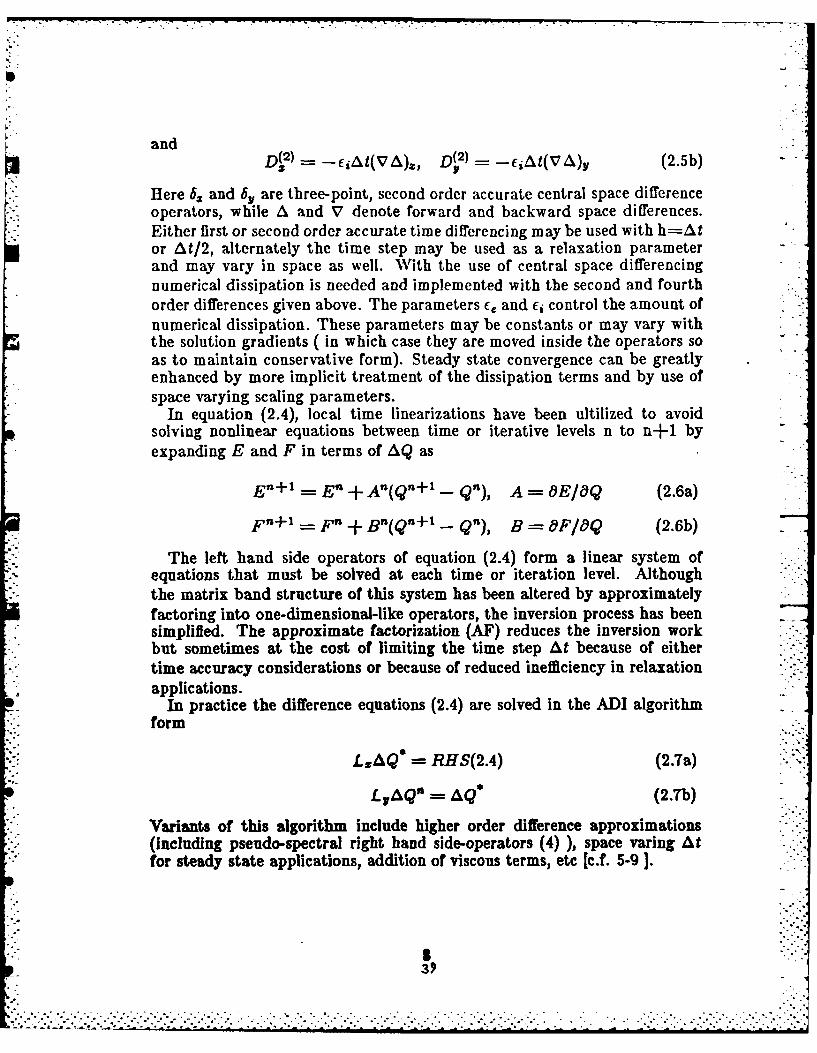
Here 64 and 6. are three-point, second order accurate central space differenceoperators, while A and V denote forward and backward space differences.Either first or second order accurate time differencing may be used with h=Ator At/2, alternately the time step may be used as a relaxation parameterand may vary in space as well. With the use of central space differencingnumerical dissipation is needed and implemented with the second and fourthorder differences given above. The parameters c, and e, control the amount ofnumerical dissipation. These parameters may be constants or may vary withthe solution gradients ( in which case they are moved inside the operators soas to maintain conservative form). Steady state convergence can be greatlyenhanced by more implicit treatment of the dissipation terms and by use ofspace varying scaling parameters.
In equation (2.4), local time linearizations have been ultilized to avoidsolving nonlinear equations between time or iterative levels n to n+1 byexpanding E and F in terms of AQ as
n+1- E n - A(Qn+l - Qn), A - OE/OQ (2.6a)
F n+ - Fn + Bn(Qn+l - Q"), B = F/ Q (2.6b)
The left hand side operators of equation (2.4) form a linear system ofequations that must be solved at each time or iteration level. Althoughthe matrix band structure of this system has been altered by approximatelyfactoring into one-dimensional-like operators, the inversion process has beensimplified. The approximate factorization (AF) reduces the inversion workbut sometimes at the cost of limiting the time step At because of eithertime accuracy considerations or because of reduced inefficiency in relaxationapplications.
In practice the difference equations (2.4) are solved in the ADI algorithmform
"-- RHS(2.4) (2.7a)
LAQ" = AQ (2.Th)
Variants of this algorithm include higher order difference approximations(including pseudo-spectral right hand side-operators (4) ), space varing Atfor steady state applications, addition of viscous terms, etc [c.f. 5-9 ].
3. ",-o'.

b) DiagonalizationEfforts have been made to reduce the inversion work over and above
what is obtained with approximate factorization. In particular, Pulliam andChaussee7 have used eigenvector-similarity transforms to reduce the blocktridiagonal matrices to scalar tridiagonals( see also Chaussee and Pulliam8 ,Steger, Pulliam and Chima , Coakley t0). Specifically, the eigenvectors of theA and B Jacobian matrices, denoted as X and Y, are further approximatelyfactored into the left hand side of equation (2.4) as
XI+ hg,,AA~ n+ (2)]X-1Y I + h6 yAB~ n+ (2)]Y_1Qn(28• (2.8)
-At[6E n + 6 Fn + D(4)Qn]
whereAA- X-AX and AB= Y -'BY
As Figure 1 illustrates, the number of operations in solving a block tridiagonal( that uses only L-U decomposition ) increases with the cube of the blocksize, a formula given by Merriam I' indicates the work increases as Ym3 +
m2 - im where m is the dimension of the block. Specifically our own coded4 x 4 block solver requires 370 operations per entry (i.e. grid point) while the1 x 1 tridiagonal needed in (2.8) requires only 9 operations per entry (or 36operations for 4 scalar tridiagonals). Although the eigenvector matrices mustbe formed and multiplied through (each 4 X 4 multiply requires 28 operationsper entry), the arithmetic operation count of equations (2.8) is considerabllyreduced from that of equations(2.4). For block tridiagonal matrices subjectto periodicity conditions and for block pentadiagonal matrices the saving iseven more significant.
c) Sound Speed and Velocity SplittingAn alternate method for reducing the inversion (i.e. solution ) work was
proposed and demonstrated in reference [1.This method was also motivatedby similarity transforms, but it does not explicitly use them in the algorithm.Instead, it involves splitting the Jacobian matrices A and B into velocity andsound speed ( or pressure parts) as
A -Au +A& (2.9a)
B=Bu+Bc (0.9h)
e....
o~~~~~~~~~~~~~~~...-. ,-..°-.-.,... o. .... •.°. . .. ... .o.......... ..... ... ........

such that the eigcnvalues or(A) and or(B) are
or(A) or(Au) + c(Ac) (2. 1Oa)
or(B) = 7(Bu) +o,(Bc) (2.10b)
w ith
o,(Au) =(u,ut, u, u), r(Ac) =(0, c,0, - c) (2.11la)
or(B.) = (v, v, v,v), o,(Bc) =(0,0, c,- C) (2.11b)
The matrices Au, A,, B, and B, were round from a natural reduced form ofthe equations in nonconservative from. Specifically Ac and Bc were split, as
0 o 0 0 0 0 01
(U2 + V2)/2 -u& -v1 0 0 0 olA.2 0 0 0 0 B, (U{ + V2 )/2 -u -v
CV
wherej~~~ =U [u2 + V2)/1--)2
4 yp-p, 1)21-
=[u 2 + V2 )/]--12b~~c= PyU )217p/[p (,y -
while A. and B., are
Aw =A-Ac(2.13a)
B,=B- Be (2.13b)
This splitting produces matrices A. and B,, that are more complex than Aand B. However, Steger [1] noted that Qis an eigenvector of both matrices,i.e.
AuQ =uQ (2.14a)
Q vQ (2.14b)
which prompted the ad hoc substitution
S41

AQ ( uI+ A)Q (2.15a)
BQ (vi1 + Bc)Q (2.15b)
The matrices uI + A, and vI + B, have a reduced form that simplifiesinversion compared to A and B.
Insertion of equation (2.15) into the equations for local linearization of theJacobians (2.6) produces *
En+l - En + (Ul +Ac)n(Qn+l - Qn) (2.16a)
F -+ 1 = F n + (vI + Bc)n(Qn+l - Qn ) (2.16b) -
SUitilizing these linearizations in the basic algorithm equation(2.4)
LZL AQ = RHS(2.4) (2.17)
gives new left hand side operators L, and L. that are easier to solve
L= I + h6x(u! l A,)n + D (2) (2.18a)
L1 I + h6(vi + B,)" + D 2) (2.18b)
The end result of this splitting is that the new operators L, and L, formmatrices that no longer require 4 x 4 block tridiagonal inversions. Leavingout the dissipation terms to illustrate the structure of these operators, weobtain
'1 0 0 0f u 0 0 0o 1 0 0 a, u+aO2 a', a
Lx- 0 0 1 0 +At6z 0 0 u 0 (2.19a)
0 0 0 1 a4 a42 a43 u+a 4
'1 0 0 0" v 0 0 0
0 1 0 0 0 v 0 0
Ly 0 0 1 0 + At6, b 1 be2 v-+b, b 4 (2.19b)0 0 0 1 b 1 b42 b3 v+ b 4
- ..
t ~. . . . . . . . . . . . . . . .
43 44-.. .L:::}i!

where a' and b' are the respective elements of A, and B, given by equation(2.12).
For the L, operator, for example, the first and third rows decouple from thesystem and can be solved as scalar tridiagonal matrices with their respectiveright band sides. Once these rows are solved, the elements of the first andthird columns can be moved to the right hand side. The second and fourthequation remain coupled and are solved as a 2 x 2 block tridiagonal matrix.The dissipation terms also form diagonal tridiagonals and so do not alter thestructure. The block decoupling of the L. operator is even more conspicuousand is inverted (i.e. solved for ) in a similar manner.
Substitution of the left hand side operators given by (2.18) in place ofthose of (2.7) results in a substantial reduction in arithmetic operations. Ourtypical 2 X 2 block tridiagonal requires 55 operations per point, so the overallinversion, including the two scalar tridiagonals, requires 73 operations perentry. Because the two scalar tridiagonals have identical coefficients this workcan be even further cut by solving them together.
The matrix splitting (2.15) produces the flux vectors
E AQ uIQ + AcQ =E + Ec (2.20a)
F zBQ= vIQ +BcQ F+ F (2.20b)
where
rpu pV 0[j [ye,~V 0,-- t,,V 2c 0o F" |P|F- (2.21) :-
,L Ue .J t P VC J p-
Note that we do not reproduce the matrix splitting (2.9) ( with A, and B,defined from (2.12)) by taking the Jacobians of (2.21). Surprisingly, linearstability analysis ( see Appendix B) as well as numerical experiment haveshown that the use of the Jacobian matrices for AC and B, is unsatisfac-tory. However, the same stability analysis and numerical experimentationhave confirmed that no numerical stability degradation occurs by using thesubstitute linearization matrices (2.15). But, the linearization (2.16) is onlyfirst order accurate because of the substitution (2.14).
The matrix splitting concept can be extended to three dimensions. In thiscase the difference equations can be represented by
LL,L(Qn+l - Q") -- At[6 8E" + 6,F" + 6xGn + D(4)Qnj (2.21)
43
, ... ,., ...... ...... .......... .. .......... .....-.....-.... ....... ,...,........-.....-.......

Associated 'with each operator are 5 x 5 block tridiagonal matrices, wvith eachmatrix inversion requiring about 700 operations per grid point. Typically theinversion represents 70 to 80 per cent of the overall work per point. Replacingeeach Jacobian A by 0l + A, etc. reduces the inversion cost from 700 to82 operations per entry of each block tridiagonal. By combining the scalartridiagonals, this can be cut to 74 operations.

- -- . -P . - I . - * I -- -
MI. Sound Speed and Velocity Splitting in Steady Generalized Coordinates
The two - dimensional Euler equations can be transformed from Cartesiancoordinates to steady curvilinear coordinates using- new in dependent variables
The Euler equations written in steady generalized curvilinear coordinatesare
Oro atk+ 0,P 0(3.2)
pU [ pV 1PUpvU + &4'P J-Ij J-1pL'V + VxP
eU(e+ p) JV(e + p)
where J is the Jacobian Gj7 - y7 and
U=G2 U+ 1 V, V=,,xU+77yV
are unscaled contravariant velocity components.
Application of the AIF implicit scheme (2.4) to equation (3.2) is given by
I h( D +5,g't+D 2 ] &o3a
'where =E~J'vA) V,,)JD s)2 (V r,&,72j j(3-3b)
and
Dr fi~tJVA.J q eAJV,&, (3.3c)
The Jacobian matrices of Pand P can 'be given in terms of the Jacobianmatrices A and B as
A = .A+e.yB (3.4a)

B = YpA + ?yB (3.4b)
Making the substitutions of (2.15) into A and BQ results in
= (UI + CAc + CyB)e (3.5a)
f3Q (VI + ?izAc + ?1 Bc)Q (3.5b)
Because of the linear combination of both Ac and Bc being present inEq.(3.5), only 3 x 3 reducibility is achieved. When applied in the implicitAF algorithm, this results in a savings as indicated in Ref.1, but not as greata saving as what was achieved in Cartesian coordinates. Moreover, in threedimensions one can only reduce to a 4 X 4 block tridiagonal. --
The transformed equations given above have only been transformed in theirindependent variables. That is, Cartesian velocity or momentum componentshave been kept, and, as a result, the so called strong conservation law form ismaintained. Suppose, for example, we had used orthogonal body coordinatess and n, and that we transformed the momentum components as well. We'would then obtain equations with coordinate source terms, but otherwisethe equations would look like their Cartesian counterparts and the Jacobianmatrices could be reduced as before. We can achieve this same effect withequation (3.2) by multiplying through by the matrix
::'1 0 0 0 -':
C (3.6)
':LO 0 0 .'-.
This matrix transforms uv momentum components to UV components.With multiplication of (3.2) by C we obtain
- PUU + P(V.V) I PUV + p(Vc. V,).-. + OfJ- + , 1. j- H (3.T)P" PVU + Ave. V) j pV, + p(V, ).-
t'i IL Ul+ P) J L V(ep)
withH -C[(Ce)-'E + (C -F)
These equations look much like their Cartesian counterparts except forthe coordinate source term and the appearance of two extra pressure terms.
::: -.•
oo'

However, for orthogonal coordinates, V . = 0, and the extra pressureterms then drop out. Although we will not give the details here, one cananticipate from the form of the equations that the flux Jacobians in theimplicit algorithm are 2 X 2 reduciable ( here the Jacobian matrices are formedwith respect to pU and pV components, not pu and pv components). So ifthe coordinate generated source term is either treated explicitly or properlydistributed in the LC or L, operators, the inversion efficiency of the previoussection can be obtained.
Generally the transformed coordinates will not be orthogonal and multi-plication through by C will not lead to the 2 X 2 reduced matrix operators.However, if we use a transform matrix that brings out a mixture of con-travariant and covariant velocity components, the extra pressure terms willalso disappear. Although it may not be immediately obvious, we can againobtain the reduced matrix operator structure without requiring the coor-dinates to be orthogonal.
Consider the transform matrix C! given by
= 0 (3.8)
LO 0 0 -'
where
4: 2 VV V-
and the inner 2 x 2 of C transforms u and v into the covariant velocitycomponents
U =q£ 1(vyU - izV), V - C 1 (- ~U + GV)
Since the determinant of C is JI j1 1 , its inverse exists for all mappings ofinterest and is
.1 0 0 0"0.O-- _.. 2a - I 0(3.9)
0 0
47... . - - A - S~ 1 *a .C.-S .A A A h °i' . '

Multipling equation (3.2) by C we obtain
OQ + OCE + 0F = H (3.10)
where H = + : F)H{ -c(cC E + Cq- F) '-
and Q = CQ, £ = CE, F -- P. The flux vectors written out are
SpU 1PV/1A,.IuI +~ ,1 p Jp 2 pUrV j~~I Pl Th=Ju pUpVV + Jp/e1
ILe k U(e+p) " V(e+p)(3.11)
Unlike equation (3.7) extra pressure terms are not picked up in the momentumequations.
The previous numerical algorithm extended to equation (3.10) is given by
+ h5 A" + + h61,B" + D(2)]A =(.2
-At 6CR" + 6,FP + i' + D(4)Q"]
where we have lagged the source term and where A OE/OQ andB =-
It can be verified that A = CAC - 1 and B = CBC -. Using theserelations as well as (3.5) we find
AQ = (U! + Ac)Q BQ - (VI + B)Q (3.13)
with
0 0 0 01.I(u2-,+- 2)/(2t2 ) -U -VIz/f2 J/121a ¢"
.; ( (7 - (8.14a)
641 642 643r 0 0 0 01
B. = 0 Oj(3.14b).b, - 1 z .u2 + ,,,2)/(29,L) -oI2/1 -V .rIL : -
48
... ~............-......6h......v .
------------------------------------------------- -- 7

where
a,= U[(u 2 + v2)/2 - p(p(- 1)2)]
a42 - e2[,tpe/(p(, - 1)2) -U2]
a43 = e [ 1,e 2 (p(_ - 1)2) - UVII
bc - vr(u2 + v2)/2 - 'yp/(p(' - 1)2)]
=b2 - 2[')'Pte2/(P('7 - 1)2) - jJ-]/J
b43 t- eI"pe2/(p('_, - 1)2) -V2lj
andf 12 -- /V 1
Making these substitutions into equation (3.12) we obtain the reduced formof the algorithm
I[+ h6,(UI + AJrD ) + + h6,,(VI +,), + D(2) AQB)--
+-At 6t J,+pn +r 4 )+ (3.15)
Finally, to avoid the source term as well as to take advantage of existingcodes, one can rewrite these equations in the form
+ h~(U +A,)n + p + h6q(VI + b)n +D-.,t-- E " + 6,,P + D(4)]
(3.16)
The right hand side of this equation is the same as equation (3.3a), while
the left hand side maintains the update for Q quantities rather than Q.The advantage of this last form is that one can readily take an existingcode for equation (3.2) and modify only the left hand side operators so as totake advantage of the reduced inversion work. The steady state solution ofequation (3.16) is clearly identical to that of equation (3.3a).
-2>-.7 z ":-<.... -..-: -.: ...< .-....... ,-:-..-.....-.° .,.: .....- .-:....... -... . . . . .. . . . . . . . . . . . . .-. .-...-....... ., .,.-.......,. ...... . . .. . .--

IV. ResultsThe algorithm given by equation (3.16) was tested on a NACA 0012 airfoil
under transonic flow conditions in order to verify that no adverse stabilityeffects are incurred by using the matrix reductions. Versions of the basicNASA Ames Research Center AIR2D/ARC2D, which solve equation (3.3a),were modified to the form of equation (3.16). As noted earlier, only thatportion of the code which deals with the left hand side operator has to bealtered in order to implement the new algorithm. The basic code is describedin Refs. [5,6].
A "C-type" topology was used for the airfoil calculations. The grids weregenerated with either a hyperbolic grid solver 12,13 that imposes orthogonalityup to numerical errors of truncation and smoothing, or an algebraic construc-tion that uses a method similar to the control function approach of Eiseman14 .In all cases, the far field boundaries were placed approximately 20 chordsfrom the body. Boundary conditions on the body, wake, and freestream arefurther described in Refs.[5,6].
As a first calculation, a relatively coarse grid was used which was generatedwith the hyperbolic grid solver. This grid has 157 points in the -directionand 33 points in the i7-direction (see Figures 2a-2b). The pressure distributionon the NACA 0012 for M,,- = .8 and a = 0. is shown in Figure 2c. Thisdistribution was computed using both the standard algorithm (3.3a) and thereduced matrix form (3.16). Both algorithms were run using Euler implicitdifferencing which is first order accurate in time. As shown in figure 2d, theresidual histories are virtually identical. However, the standard algorithmrequired 120 CPU seconds of CRAY-XMP time per 1000 iterations while thenew algorithm required 54 CPU seconds per 1000 iterations.
Numerical experimentation, in which At was adjusted over a wide range,has confirmed that the new algorithm is as stable as the standard algorithm.As an example of the robustness of the formulation using (3.16), a much finergrid was used to compute the previous case. Figures 3a-3b show a view ofthe grid with 249 points in the c-direction and 50 points in the -direction.The solution on this grid (Figures 3c-3d) was computed using a spaciallyvarying time step scaled by __L_ where J is the metric Jacobian. For
this calculation, the drag coefficient was both converged to 5 digits in 600iterations or 68 seconds of CRAY-XMP time. Figure 3e shows the residualhistory for this calculation.
Recently, Beam and Bailey have reported in private communication [seealso 6] that significantly faster convergence can be obtained by incorporat-
- . .
• * .. ''''' > '' .'. .i. .-.'- :". .-. '.'.". . .At -. % '. . .: tt - .'-' '- :.:...: ' ' .-. - ..- . .. .-. .-.- .: -

ing the fourth order smoothing terms implicitly into the Beam and Warmingalgorithm. For the standard algorithm, imposing fourth order dissipation im-plicitly necessitates 4 X 4 block pentadiagonal inversions which are relativelyexpensive. The reduced matrix algorithm, however, requires only scalar and2 x 2 block pentadiagonal inversions which are much less costly. In fact,a special 2 X 2 block pentadiagonal inversion algorithm, coded for this al-gorithm, requires only 107 arithmetic operations per entry.
In testing the sound speed-velocity splitting algorithm with implicit fourthorder dissipation, a more advanced form of numerical filter was implemented.This filter uses both second and fourth order differences such that the secondorder difference is dominant near shock waves. The spectral radius of theflux Jacobian matrices is used as a scaling to the smoothing coefficients in anattempt to mimick the dissipative nature of second order flux split upwindschemes 15 Full details are given in reference [6].
As a test case, an algebraic grid was used to compute the flow field arounda NACA 0012 airfoil at M.. = .8 and a = 1.25 degrees. The grid has193 points in the C-direction and 33 points in the V-direction. The grid andflow field solution are shown in figures 4a-4d. The residual history (figure4e) shows the rapid convergence. For this particular case, the CPU time onthe CRAY-XMIP was 93 seconds per 1000 iterations. This compares with 65seconds per 1000 iterations using the tridiagonal version of the new algorithmwith constant smoothing coefficients which had much slower convergence. Itshould be noted that the smoothing filter used for the pentadiagonal versionrequired 16 seconds more CPU time than the same smoothing with a constant .coefficient filter.
Our computational results verified that the reduced algorithm was every bitas numerically stable as the standard algorithm. This experience is similar towhat was observed previously by Steger on a algorithm version that reducedto a 3 x 3 block and a scalar. Here, with reduction to the 2 x 2 block, justover a factor of two was saved in overall computer time by using the reducedalgorithm (3.16) in place of (3.3a). The precise savings that can be obtainedis, of course, machine and coding dependent and a larger improvement shouldbe obtained in three dimensions.
V. Conclusions
By substituting similar reducible matrices for the Jacobian matrices ofthe flux vectors, a substantial reduction has been achieved in the arith-metic operations needed in solving approximate factorization implicit al-
........-. •- °
*.

gorithms such as Beam-Warming. Numerical calculations indicate that thenew similarity split matrices can apparently be used without any loss of pnumerical stability, although time accuracy can be degraded unless additionalsteps are taken. The new method can be readily retrofit within existing codes,and can likely be extended to viscous flow calculations as well. .•-.
o
References
(1)Steger, J. L. Coefficient Matrices for the Implicit Finite DifferenceSolution of the Inviscid Fluid Conservation Law Equations, ComputerMethods in Applied Mechanics and Engineering, vol. 13, (1978) pp.175-188.
(2) Beam, R. M. and Warming, R. F. An Implicit Finite-Difference Algorithfor Hyperbolic Systems in Conservation- Law-Form, J. Comp. Phys., Vol. 22,Sept. 1976, pp.87-110.
(3) Warming, R. F. and Beam, R. M. On the Construction and Applicationof Implicit Factored Schemes for Conservation Laws, Symposium of CFD, PNew York, April 16-17, 197, SIAM-AMS, Proceedings, vol. 11, 1977.
(4) Reddy, K. C. Pseudospectral Approximation in a Three-DimensionNavier-Stokes Code. AIAA J., Vol. 21, No.8. August,1983.
(5) Steger, J. L. Inplicit Finite Difference Simulation of Flow aboutArbitrary Two Dimensional Geometries. AIAA J., vol. 16, No.7, July 1978.
(6) Pulliam, T. H., Euler and Thin Layer Navier Stokes Codes ARC2D.ARC3D, Notes for COMPUTATIONAL FLUID DYNAMICS USER'SWORKSHOP, The University of Tennessee Space Institute, Tullahoma,Tennessee, March 12-16, 1984.
(7) Pulliam, T. H. and Chaussee, D. S., A Diagonal Form of an ImplicitApproximate-Factorization Algorithm, J. Comp. Phys., Vol. 39, No.2,Feb.1981, p.347.
(8) Chaussee, D. S. and Pulliam, T. H., A Diagonal Form of an ImplicitApproximate Factorization Algorithm with Application to a Two DimensionalInlet, AIAA J. Vol. 19, No.2, FEb. 1981, p.153.
(9) Steger, J. L., Pulliam, T. H. and Chima, R. V., An Implicit FiniteDifference Code for Inviscid and Viscous Cascade Flow, AIAA paper 80-1427,1980.
(1O)Coaldey, T. Numerical Method for Gas Dynamics CombiningCharacteristics and Conservation Concepts, AIA.A Paper 81-1257, 1981.
(ll)Merriam, M. L., On the Inversion of Block-Tridiagonals withoutStorage Constraints, NASA TM-84228, March 1982.
-. .. *. -. *~ *.~t 4o°.*. • . -

(12)Steger, J. L. and Chaussee, D., Generation of Body-Fitted CoordinatesUsing Hyperbolic Partial Differential Equations, SIAM J. Sci. Stat. Comput.,Vol 1, December 1980, pp 431-437.
(13)Kinsey, D. and Barth, T. J., Description of a Hyperbolic GridGenerating Procedure for Arbitrary Two-Dimensional Bodies, AFWAL-TM,to appear.
(14)Eiseman, P., Geometric Methods in Computational Fluid Dynamics,ICASE Report 80-11, April 18,1980.
(15)Steger, J. L., A Preliminary Study of Relaxation Methods for theInviscid Conservative Gasdynamics Equations Using Flux Vector Splitting,NASA CR-3415, March 1981.
CAN
S3 I
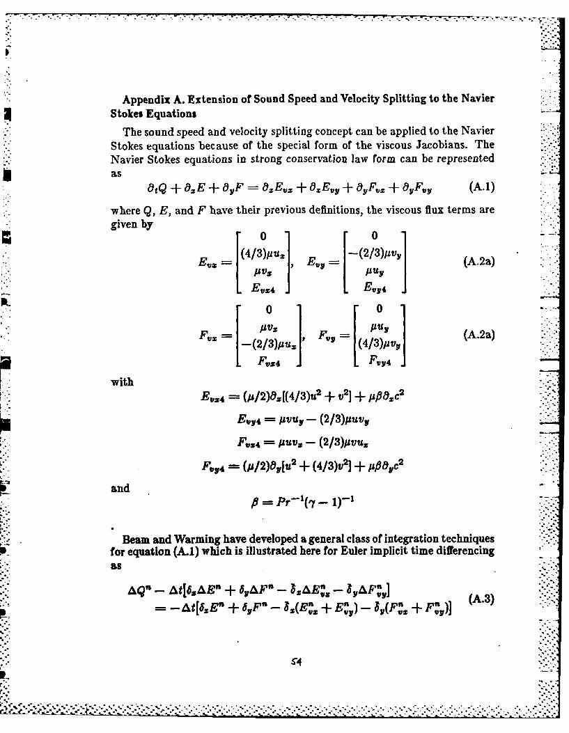
Appendix A. Extension of Sound Speed and Velocity Splitting to the Navier* Stokes Equations
The sound speed and velocity splittingr concept can be applied to the NavierStokes equations because of the special form of the viscous Jacobians. TheNavier Stokes equations in strongr conservation law form can be representedas
tOtQ + e9E + OYF i 9zEvz ± z + 'yFvz +OyFvy (A.1)
where Q, E, and F have their previous definitions, the viscous flux terms aregiven by
rw0 0
Ev E,, y (A.2a)
,Pu!
F, =[(2/3)uuj , (4/3)jpv, A.
L F~z4 J[ F,,4 j1with
BV354 =(jp/2)0j[4/3)u2 +V 2] +. po 2
E,Y4 =pvu, - (2/3)puv,
F,3 4 P V - (2/3)pvu,
FV, 4 =(p/2)19y[u2 (4/3)v2j + P85,C
andPr= ( - 1)-,
Beam and Warming have developed a general class of integration techniquesfor equation (A.1) which is illustrated here for Euler implicit time differencing
An- At[68 AEB" + 6,&F" - l&E,- 8AMY
p.., = - At[6zE" + 6yFn - 832(En + En) - 3(Fn Fn) A3
r-.

where AQn - Q,+I_ Qn and is a midpoint operator. In this algorithm thecross derivative flux terms E,, and F, are treated explicitly. As discussed byBeam and Warming, this circumvents the need to include an implicit viscousJacobain for these cross terms, and it also maintains unconditional stablilityfor the scalar model equation.
The spacial flux terms have been locally linearized in time. In locallylinearizing these terms Beam and Warming expand the viscous terms in aTaylor series using both the function and its derivative, as for example
- En = [n) - Qn) + oE] .(Qn+l - Qfl)A Z E . -- EV-E, - OQ JLOQZ
(A.4)Alternately, these terms can be expanded in terms of Q alone, for example
AE' == [-9 -]-(Qn+l Qn) (A.5)
where 28 is now a differential operator. This latter from will be used here.Typically y is not linearized in time and the Prandtl number is treated as ifit where a constant value as far as time linerization is concerned. For a termsuch as #Ou, i is frozen in time and / 0 yu expanded such as
p 14Y(pu/p) = Ioy[(poUo/Po) - (pouo/Po2 )(P - PO) + pO-'(pu - pouo)]
or in general
OxE,,= 8[EvxIo + poOZ(A,,jo(Q - Qo))]o (A.6a)
OyF ,y ,y[Fy1 o + poOy(ByIo(Q - Qo)) (A.6b)
with
0 0 0 01 0 0 0 0
-(4/3)(u/p) (4/3)p- 0 -(ulp) p0 0 0 0
= -(/p) p -(4/)(/p) 0 (4/3)p-1 0. 1 0,I ,2 ps3 P/P b, 42= 4z3 P/.(A.T).---
anda., = -(4/3)[u 2 /p]- [v2/pl + #[-(e/p) + (u2 + v2)p]
2 41

* . -' :.-. --. -,"
a=2 [(4/3) - P(u/p)
a3 = (1 - fl)(v/p)
byl - [U2/p]- (4/3)[v2/p] + ,[-(e/p) + (u2 + v2 )/p"
by2 (1-)(up)
by3 = 1(4/3) - P](v/p)
With introduction of the sound speed and velocity matrix substitutions forthe convection Jacobian matrices, we can obtain operators L. and Ly that - -
are as reducible as before because of the form of Av_ and Bvy. To illustratethis we will drop the numerical dissipation terms as before. Then Eq.(A.3)becomes
nn
LxLyAQ" -At[6zEn + 6yF" - (E 2 + Ez )- Y ( +z fY(A.8)
where
U 0 0 0 '0 0 0 0'
821 U+ 22 823 04 41 a2 0 0
Ls=I+-At5 0 0 U 0 431 1] 0 83 0
G14 4142 43 U +844 *4 42 843 d4
V, 0 0 0 '0 0 0 0)
0 0 0 V2 b2 0 0
L4=+At5 b " .b--2 'U+ bf, +U, b" 0 b3 0
be 2 bT 3 v+b 4 b 41 bb 3 b 44L 4 J L
Here I is the identity matrix and a' etc are elements of A' etc. Keep inmind that the viscous terms have been second order accurate differenced to
maintain tridiagonal structure using midpoint operators .
We can now examine the structure of L. for example, and show that theequations uncouple to two scalar and one 2 x 2 block tridiagonal. The firstrow of L, is clearly uncoupled and can be solved for as a scalar tridiagonal.Its solution is then used to update the right hand side (RHS) of rows 2, 3, and4. With the first column of the matrices brought to the RHS, the third rowis seen to be uncoupled and can thus be solved as another scalar tridiagonal.The RHS terms of the second and fourth rows can now be updated and what t
14
7°
remains is a 2 x 2 block tridiagonal to be solved. The L. operator inverts ina similar fashion.
Thus, the addition of the viscous terms in Cartesian coordinates does
not prevent the decoupling technique that was successfully used for the
inviscid gasdynamic equations. Preliminary work shows that, using the local
transformation of Section IT[, the same decoupling may be possible for the
Navier Stokes equations in generalized coordinates. This matter is being
further investigated.
IS7
. . . . . . . .-
.
,°-I
"o°°p
"pi'-
p-'i?
,o
--..., .
_____________________________ - a-.- .....-. ,- ,

Appendix B.Stability of Sound Speed and Velocity Splitting
In order to study the stablility of the algorithm proposed in Section II,the one dimensional Euler equations will be tested for linear stability using aFourier ( or matrix) analysis.
The one dimensional Euler equations in Cartesian coordinates are given by :
otQ + .,E =0 (B.1)
where
Q [PU], E [PU +P (B-2)u(e + p)
A frozen coefficient form of Eq.(B.1) is given by
tQ A'OE -0 (B.3)
where A is the true Jacobian, [OE/OQ], and * denotes that A is evaluatedusing a frozen value of Q, Q'. Implicit first order accurate differencing ofEq.(B.3) is given in delta form as
I + hA "+ Q-) = hA*6Q (B.4)
In our sound speed - velocity splitting scheme we replace the A matrix ofthe left hand side operator with the similarity matrices u I + A,7 to obtain
I h(u'I + A:)6](Qn+, - Q") -hA'6Q n (B.5)
The right hand side matrix A* is not altered in our procedure, and must notbe changed in Eq.(B.5) as it represents the correct linearization of E about
Q. The question to be addressed is Eq.(B.5) as stable as Eq.(B.4) now thatthe implicit operator as been altered?
If we were to perform a stability analysis of Eq.(B.4) we would diagonalizeA' using its eigenvectors. We can then readily perform the stability analysisfor difference equations corresponding to scalar partial differential equations.For Eq.(B.5) we can use the eigenvectors of A* to diagonalize u'I+A, but theright hand side matrix will not be brought into diagonal form. Nevertheless,we find that the resulting equations can still be analyzed.
.. .. . .. . .. . . .. .. :c::c: .'> : ';I..: ... :.: . . . .: < - > .- *.* % *~ -. "

The matrix A, for one dimensional flow is given by
- 1u/2 -u ] (B.6)
1a a42 ..,where
a4- ulu 2 2- c2/(- 1)2]
a 2 -u 2 + c2/(,y 1)2Eigenvectors matrices of A, are given by
[(-'y - 1)u2 + 2cu]/(4c) [(y - 1)u + c]/(2c) -(y -y 1)/(2C)]X-- [(y7- 1)u2- 2cu]/(4c) 1-[(- l)u- c]/(2c) (y7- 1)/(2c)
1 0 0(B.T)
0 0
X= 1 (B.8):.. u-(Cl(, - 1)) U -(c/('-- 1)) U221 i-'
and-C 0 0
AA. X-AX 0 c (B.9)00
Multiplying Eq.(B.5) by the frozen-coefficient inverse of the eigenvectors--(X*)-I gives
,....'""1-4- hl~l J 6.X*)-,(Qn*+ l Qn) __h(*-'A*X*6z(X,)_IQn .-.. .+ h(u*I + A;6)6]Xr(B1-Ql h(X)AX6 xln
_ (B.10)or in nondelta form with W - (X*)-IQ
+ h(u* + A%)6, Wn+'- I-h(X*)-AX*-u*I-Aj6.W W (B.11)
However, (X*)-A*X* - u*I - A% is a very simple matrix-'A*X* -roooi
(X*)-AX- - = 0 0 (B.12)
1
., , _'-": .. '• _.._.• ..... ,.. . . . , ., . . .. . *. ... . . . . . . .-. '

77. ~~- --- - - . - . -
. . .. .. . 7 7
p
Assuming periodic boundary conditions so as to use a Fourier stabilityanalysis (or the matrix stablity method using circulant matrices), the finitedifference operator b.. can be transformed to
2isin(Oj)
2 A z
" "
and W denotes Fourier transformation of W { i.e. transformation via theeigenvectors of a circulant matrix).
Applying the Fourier method to Eq.(B.11) and taking the inverse of theleft hand side operator gives
I
l+ihc( o 1 0 01
--" 01 ]17" (B.13)
0+ h0u -ilrt -ihic
or0 01wn+l --1+h(+) n ::. -
S+sh 0 0(-c W (B.14)
The amplification matrix associated with Eq.(B.14) is lower triangular.Therefore, its eigenvalues are the diagonal elements, and these clearly havemodulus less than one for any positive value of h = At. In fact, these eigen-values are identical to those obtained with the standard scheme given by..-Eq.(B.4). Thus the necessary condition for stability is met for any values ofh. A sufficient conditionfor stability requires bounding the norm of the 3 x 3amplification matrix. Observing the 3,1 and 3,2 elements it is clear that thet. norm can be unbounded for u -. 0 and h --, o, however, even in thisnorm powers of the amplification matrix will be quickly bounded unless u isidentically zero.
It is interesting to note that if one were to form A, using the Jacobian ofEc, the resulting algorithm is unconditionally unstable. In this case A. isgiven as
0 0 0Ac=()-1) u212 -u 1 (B.15)
a4, a42 U]
where= U[u 2/2 - C2 - )'""
1..2:s ::.:::-

a 2 - --u 2 +-1c 2 fr(W - 1) ...
Proceding in a similar fashion as above, the resultant representation in Fourierspace for (B.5) is
2i#+ihrcc ihxcc 0
-- 2 i= e 29-ihcc o W (B.16)
where
The maximum eigenvalue of the amplification matrix in (B.16) can be shownto be greater than one for all At's greater that zero and the necessarycondition for stability can not be met. In actual numerical experimentationwhere numerical dissipation is added, small values of At could be used toobtain stable results.
."'
*. .
:':- .

I
FIGURES
Figure 1. Arithmetic operation counts of block .tridiagonals usingL-U decomposition.
Figure 2a. Overview of 157 x 33 -rid generated about NACA -A 2airfoil using hyperbolic grid generator.
Figure 2b. Detail near body of 157 x 33 grid.
Figure 2c. Pressure distribution on NACA 0012 airfoil (M -- .80and a -0.0)
Figure 2d. Residual history comparison between reduced matrixform and standard algorithms.
Figure 3a. Overview of 249 x 50 grid generated about NACA 0012airfoil using hyperbolic grid generator.
Figure 3b. Detail near body of 249 x 50 grid.
Figure 3c. Pressure distribution on NACA 0012 airfoil (M -- .80and a 0.0).
Figure 3d. Pressure contours near airfoil.
Figure 3e. Residual history for reduced matrix algorithm with scaledAt. L-5=
Figure 4a. Overview of 193 X 33 grid generated about NACA 0012airfoil using hyperbolic grid generator.
Figure 4b. Detail near body of 193 x 33 grid. j.
Figure 4c. Pressure distribution on airfoil (M. - .80 and a =
1.25).,::: '
Figure 4d. Pressure contours near airfoil.
Figure 4e. Residual history for reduced matrix algorithm with scaledAt and pentadiagonal inversions.
. . . .*

OPERATION COUNTS FOR BLOCK SOLVERS
00
00-
0 . 1. 2. 3. 4. 5. . 7.
0UBOKSZ

C
C) ) V
U')
OL0
CDUC.)2
EA-.
CD '3
0Czc
a: ___ m
O0E 0 6 -l o ol O.s 0 0 O'- o o - o-l ., -o s -9
P-2d00 ___SI It__Sr SN HW-W M f eSr ' 0 am

.0
CD
xW,
CD C0
wU
CD,
* -F. 2b
o* crsgi Aga !w-w m v c ~i vro sI

C)0
DO~OD
at:)
* bCD
CDJ~JC:D Lfl
* CD(nLJ
(U)
* (L1I3
0m
(rir
olLSI- 01-SJCo-oS.oa] 'l w
0*0L LI 1 tXASW SN HW- lttWO 3UKI-0 iMW.,) 4

RESIOUFIL COMPARISONNO ALGORITHM ENHANCEMENTS
DT .2, SMU-1.2,SMUIM=2.5
157X33 C-MESH, M-.8O,ARLPHA=O.
4.6
o0. 0. 0. 0. 0. 0 .
ITRAIO

77-7577
wr
0
'II U
0*0~~~~~~~L WVJGI U 3W W HVOW mlw csr r A

00
CCD
1 03
x3
0) I
Vo 010 0- c*0
0- WS A W LU'r M W- Z ONO

* . ~- a .CDf-
CD
0D 0Dt
CY)
r 0
LICD)
CL
+ )
203 0- O 01 l
0* SGI I 3 U LOO m -)c irrw am

00T
:Ol 0
009. w0 .
cm.
C;,
0.700
U)r
CD
8 00
C) 0 C
(. LU 0
Ate -0
0 00oc? o - -
0~( 3 ~tn11)0 i OLD Lf0fO§HI-.,n8L) L~Rga)L,( l
-~ F. 39L
* *U Id9S1O It XUAS34VS4 HLw9-r nel lv MAot m , "

ALGORITHM WITH VARlABLE OT
NO OTHER ALGORITHMI ENHANCEMENTS
SMU-I.2,SfIUIM=2.5 249XS0 C-MESH
CD--
No-
OCD-
xa
0. 0. 0. 000 800 10.
ITRTO

-LI)
r)
0j
C3.
0f
0-se 0-o 0-l 001 OS A 0-s 0-1- 0si- 0-o- OS, 0
0* imi II UAM W LW-G 16 'W IES= QQQS4Q 90 -
___cI

. ~ .. .-. .I . . -
12
19111
* CDP-4 __J_._
I I. f i l
9F0-
o4 wsoi As. m wnw slm-esuc-oc

0-00
100
zz
*c-
0*6b-WSIGIt UA 3WVUSU HLUG-W M '8s. u 0

C: Ln m . . ..-. '-- -
0O(
~ OLD
(nn
ULr)
;00CDC!
C-) 0 C)
0I SI* C
0-0
C'3
O ST ll S 010 S1o- 01- SI- olz-
00 OOCCC000C
C N if%.('3WR!rn
.4id
O'SWWSSIO It XUA S3rdvSUM HLVUS-W m rm a1S 'ACS3ml M-OrE0 fJ~

ENHRNCEO RLGORI1THM193X33 C-TYPE MIESH
* M-.80,RLPHR=1 .25PENTA I AGONAL INVERSIONS
-0C
0'-4
CM
0l6. 0. 000600-4.0 10.
0TR9TO

FILMED
1-85
DTIC