Hyper-Modification of Canon 450D (XSi) Cameras
28
Hyper-Mod on Peltier Cooling of CMOS in Canon 450D (XSi) Camera By Anat Ruangrassamee, Ph.D. Bangkok, Thailand [email protected] What is the hyper-mod? It is the modification to directly cool a CMOS chip inside a Canon 450D camera. The purpose is to reduce dark current noise which usually rises with temperature. Then, photographers will get much cleaner images for post-processing. How does a 450D work? When the CMOS chip is cooled, the camera must be sealed inside a chamber to prevent condensation. The first step in my attempt is to understand how electronics inside a 450D works. Initially, I tried disconnecting the ribbon cable from a LCD display on the camera back and I was surprised to find that the camera still worked properly. So, the journey began. I connected my camera to a notebook computer using EOS utility (Software that comes with a 450D) and started removing ribbon cables out one-by-one and checked which features lost because of disconnection of cables. The figure shows the ribbon cables and their functions. Marked in red are cables needed for the camera to run properly for astroimaging. They are cables connecting to: 1) CMOS (of course ☺ ) 2) Shutter and mirror motor 3) Power circuit 4) Control panel on the top of the camera (on-off switch, exposure mode, flash, etc.) With these four components, we can control the camera from EOS Utility.
Transcript of Hyper-Modification of Canon 450D (XSi) Cameras
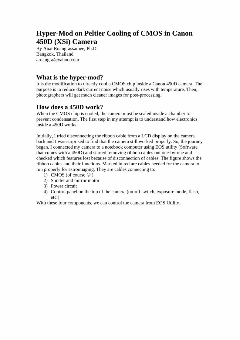
Hyper-Mod on Peltier Cooling of CMOS in Canon 450D (XSi) Camera By Anat Ruangrassamee, Ph.D. Bangkok, Thailand [email protected] What is the hyper-mod? It is the modification to directly cool a CMOS chip inside a Canon 450D camera. The purpose is to reduce dark current noise which usually rises with temperature. Then, photographers will get much cleaner images for post-processing. How does a 450D work? When the CMOS chip is cooled, the camera must be sealed inside a chamber to prevent condensation. The first step in my attempt is to understand how electronics inside a 450D works. Initially, I tried disconnecting the ribbon cable from a LCD display on the camera back and I was surprised to find that the camera still worked properly. So, the journey began. I connected my camera to a notebook computer using EOS utility (Software that comes with a 450D) and started removing ribbon cables out one-by-one and checked which features lost because of disconnection of cables. The figure shows the ribbon cables and their functions. Marked in red are cables needed for the camera to run properly for astroimaging. They are cables connecting to:
1) CMOS (of course ☺ ) 2) Shutter and mirror motor 3) Power circuit 4) Control panel on the top of the camera (on-off switch, exposure mode, flash,
etc.) With these four components, we can control the camera from EOS Utility.
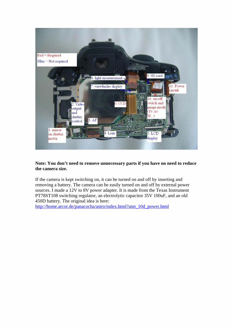
Note: You don’t need to remove unnecessary parts if you have no need to reduce the camera size. If the camera is kept switching on, it can be turned on and off by inserting and removing a battery. The camera can be easily turned on and off by external power sources. I made a 12V to 8V power adapter. It is made from the Texas Instrument PT78ST108 switching regulator, an electrolytic capacitor 35V 100uF, and an old 450D battery. The original idea is here: http://home.arcor.de/panacocha/astro/index.html?atm_10d_power.html
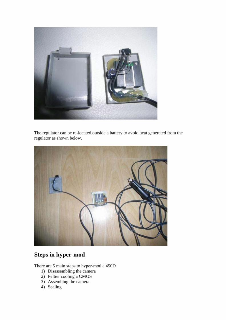
The regulator can be re-located outside a battery to avoid heat generated from the regulator as shown below.
Steps in hyper-mod There are 5 main steps to hyper-mod a 450D
1) Disassembling the camera 2) Peltier cooling a CMOS 3) Assembing the camera 4) Sealing
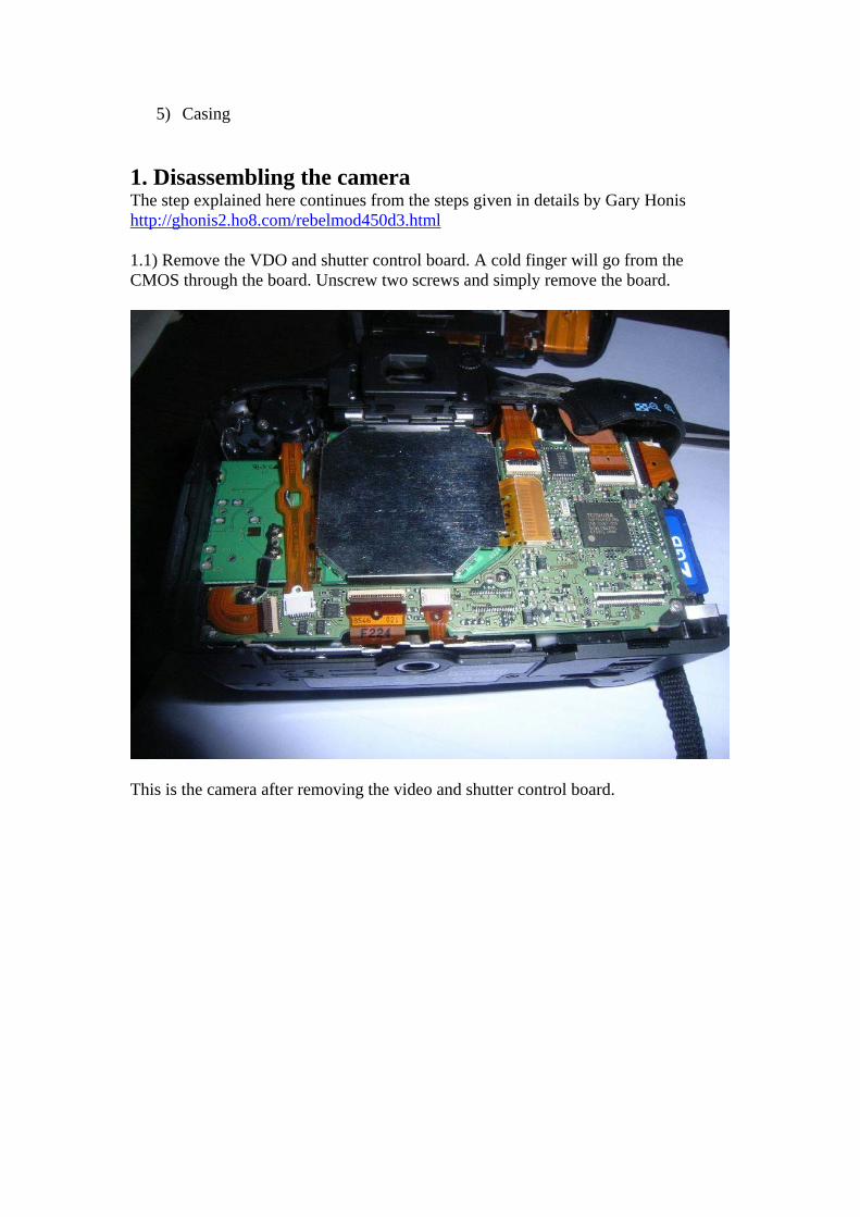
5) Casing 1. Disassembling the camera The step explained here continues from the steps given in details by Gary Honis http://ghonis2.ho8.com/rebelmod450d3.html 1.1) Remove the VDO and shutter control board. A cold finger will go from the CMOS through the board. Unscrew two screws and simply remove the board.
This is the camera after removing the video and shutter control board.
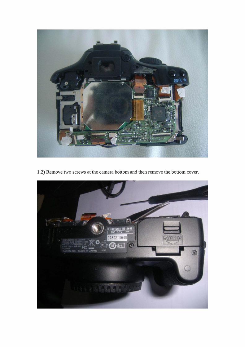
1.2) Remove two screws at the camera bottom and then remove the bottom cover.
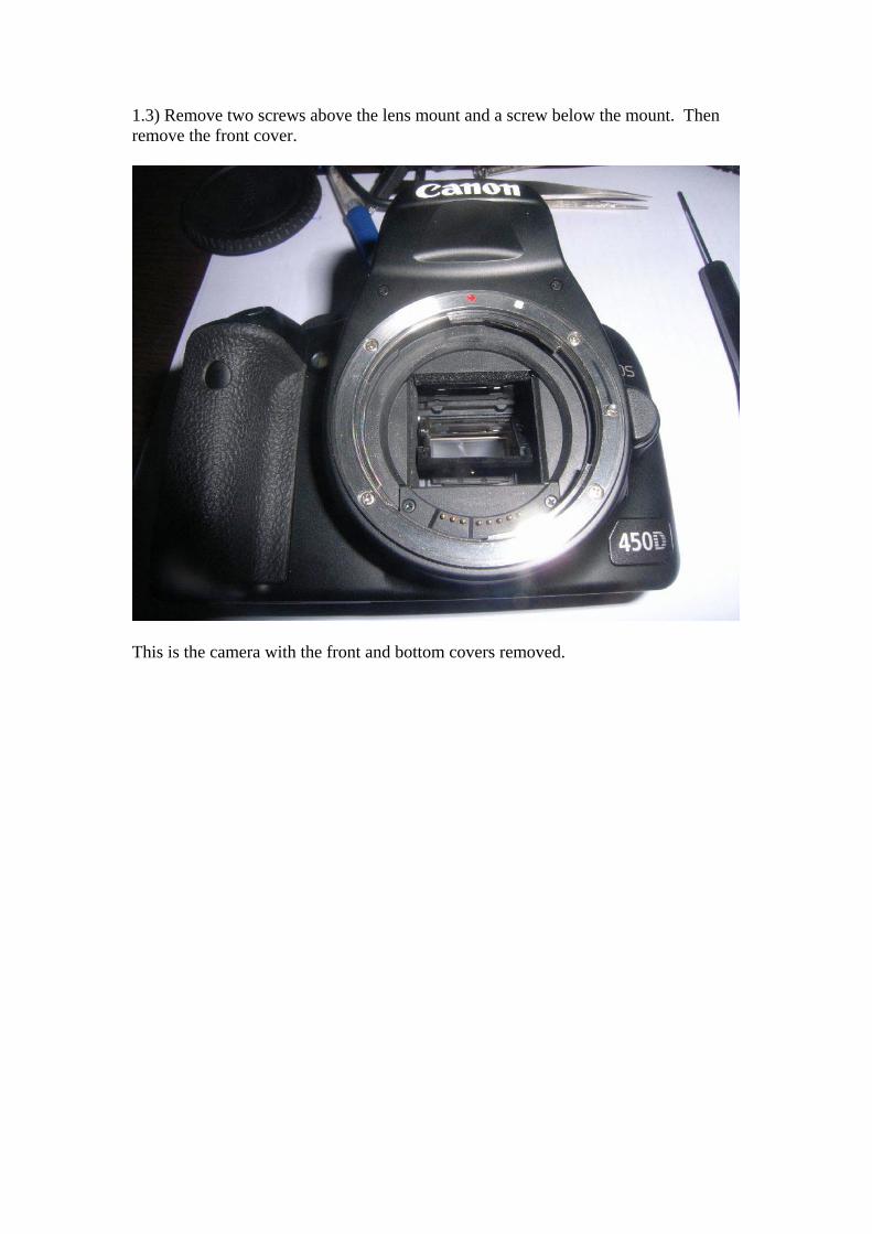
1.3) Remove two screws above the lens mount and a screw below the mount. Then remove the front cover.
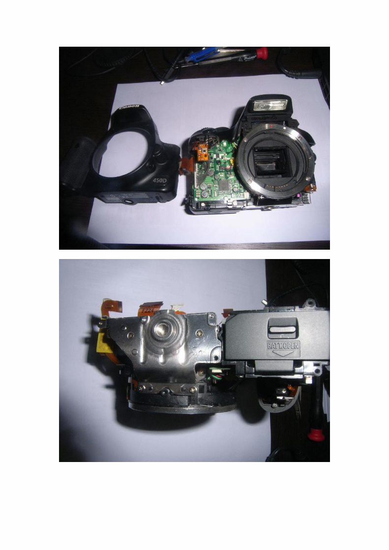
This is the camera with the front and bottom covers removed.
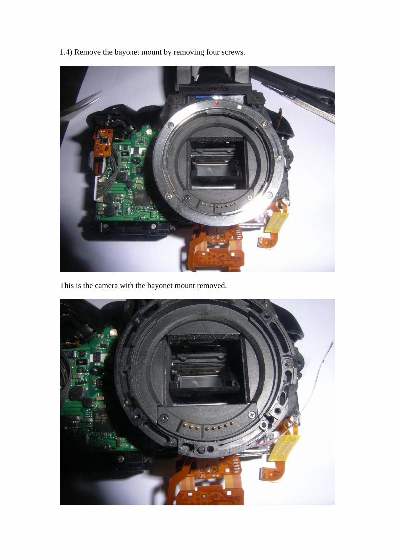
1.4) Remove the bayonet mount by removing four screws.
This is the camera with the bayonet mount removed.
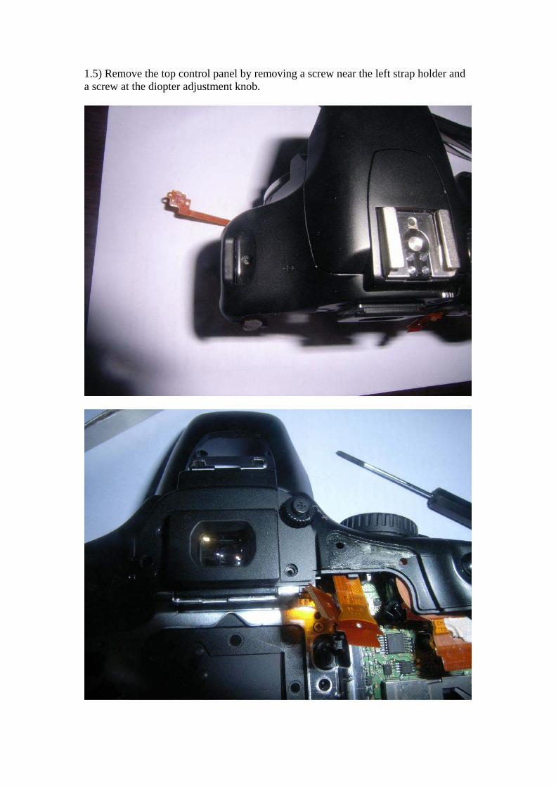
1.5) Remove the top control panel by removing a screw near the left strap holder and a screw at the diopter adjustment knob.
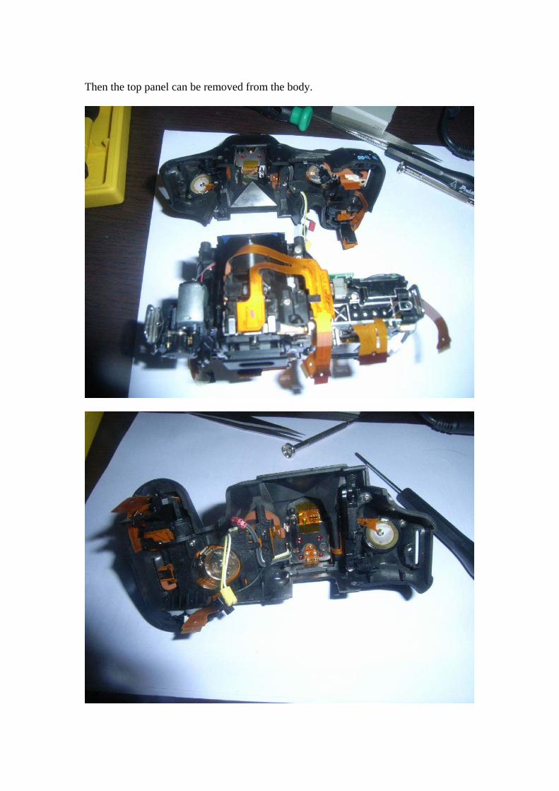
Then the top panel can be removed from the body.
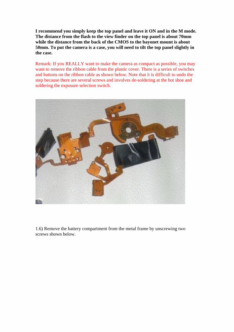
I recommend you simply keep the top panel and leave it ON and in the M mode. The distance from the flash to the view finder on the top panel is about 70mm while the distance from the back of the CMOS to the bayonet mount is about 50mm. To put the camera is a case, you will need to tilt the top panel slightly in the case. Remark: If you REALLY want to make the camera as compact as possible, you may want to remove the ribbon cable from the plastic cover. There is a series of switches and buttons on the ribbon cable as shown below. Note that it is difficult to undo the step because there are several screws and involves de-soldering at the hot shoe and soldering the exposure selection switch.
1.6) Remove the battery compartment from the metal frame by unscrewing two screws shown below.
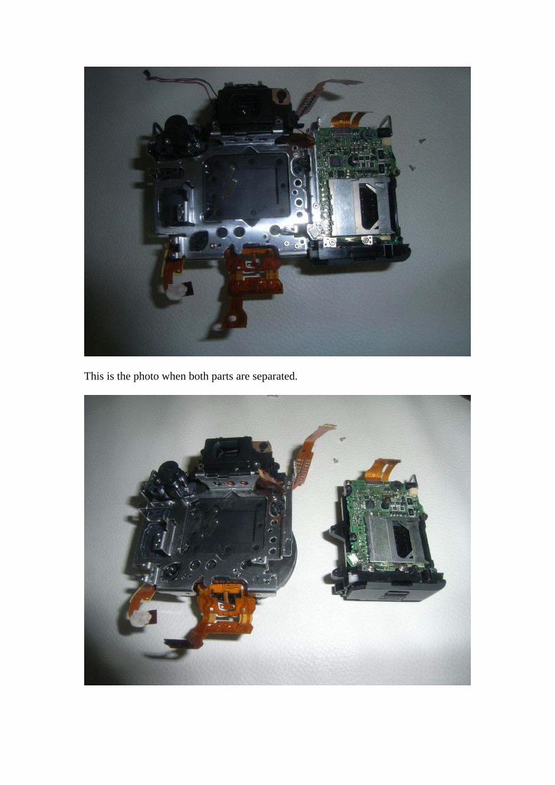
This is the photo when both parts are separated.
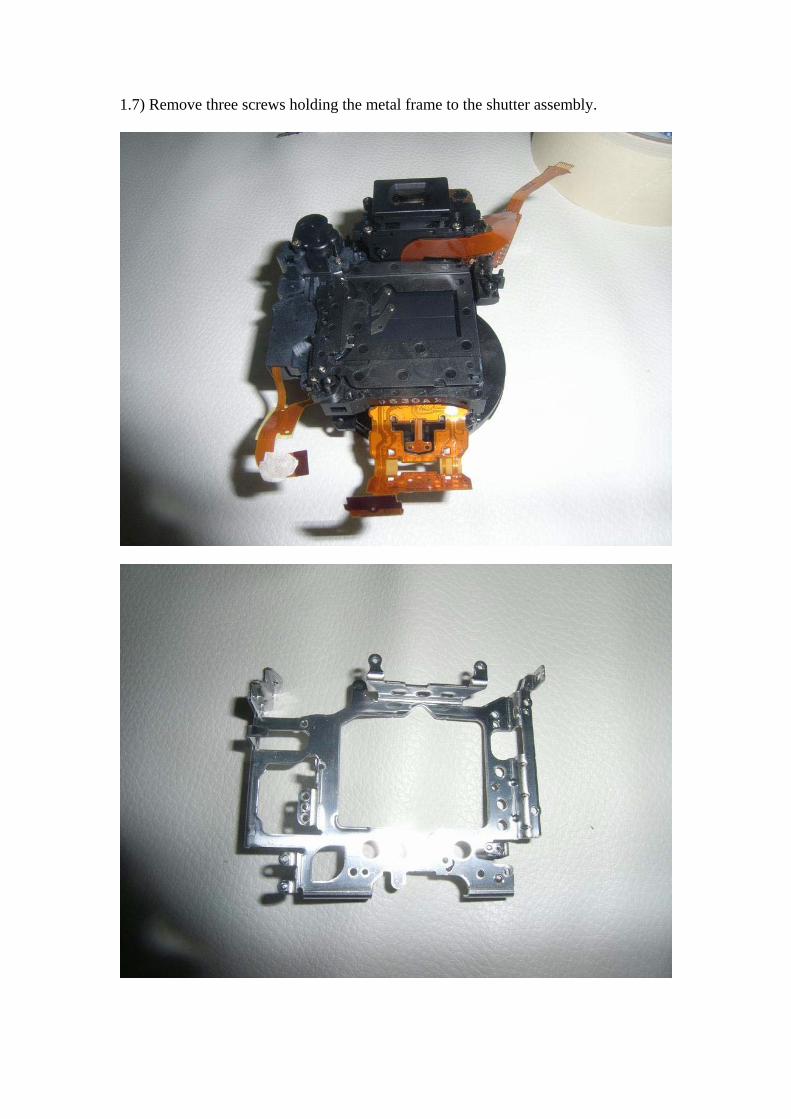
1.7) Remove three screws holding the metal frame to the shutter assembly.
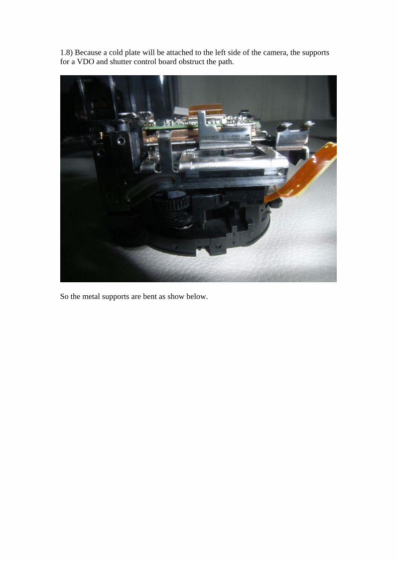
1.8) Because a cold plate will be attached to the left side of the camera, the supports for a VDO and shutter control board obstruct the path.
So the metal supports are bent as show below.
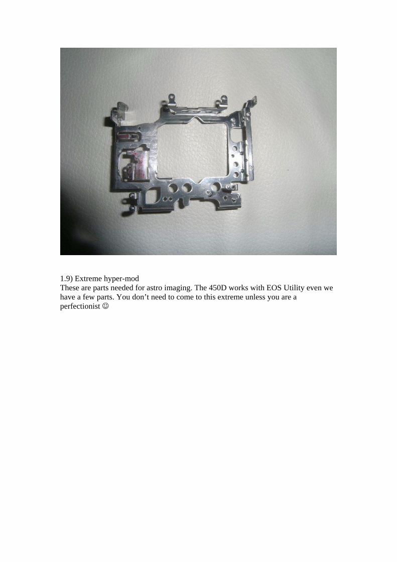
1.9) Extreme hyper-mod These are parts needed for astro imaging. The 450D works with EOS Utility even we have a few parts. You don’t need to come to this extreme unless you are a perfectionist ☺
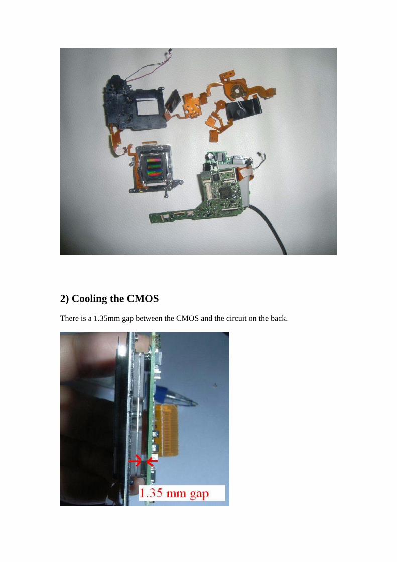
2) Cooling the CMOS There is a 1.35mm gap between the CMOS and the circuit on the back.
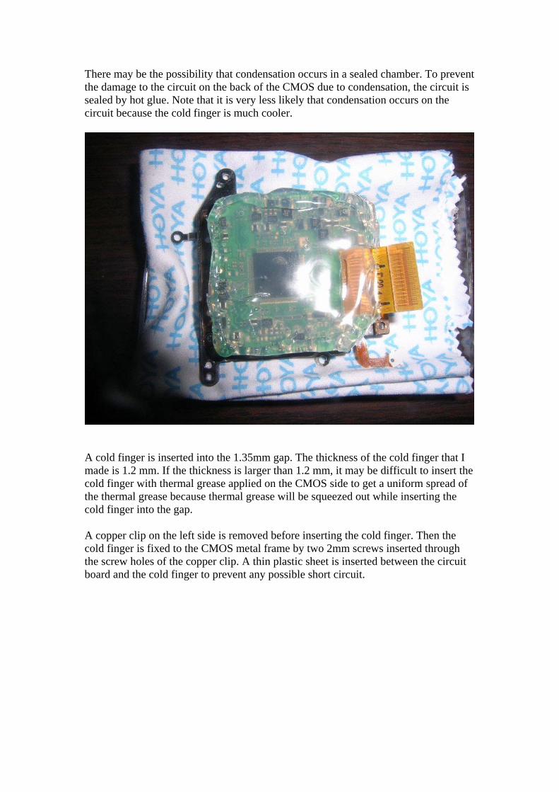
There may be the possibility that condensation occurs in a sealed chamber. To prevent the damage to the circuit on the back of the CMOS due to condensation, the circuit is sealed by hot glue. Note that it is very less likely that condensation occurs on the circuit because the cold finger is much cooler.
A cold finger is inserted into the 1.35mm gap. The thickness of the cold finger that I made is 1.2 mm. If the thickness is larger than 1.2 mm, it may be difficult to insert the cold finger with thermal grease applied on the CMOS side to get a uniform spread of the thermal grease because thermal grease will be squeezed out while inserting the cold finger into the gap. A copper clip on the left side is removed before inserting the cold finger. Then the cold finger is fixed to the CMOS metal frame by two 2mm screws inserted through the screw holes of the copper clip. A thin plastic sheet is inserted between the circuit board and the cold finger to prevent any possible short circuit.
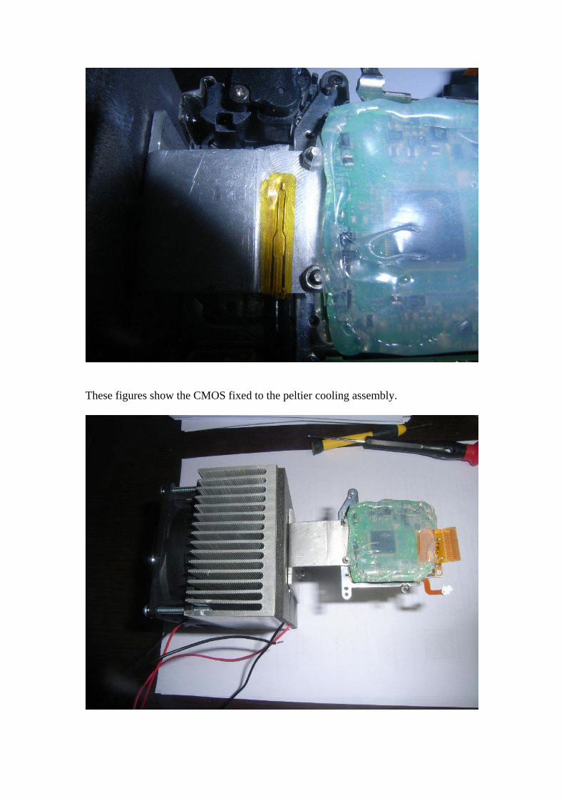
These figures show the CMOS fixed to the peltier cooling assembly.
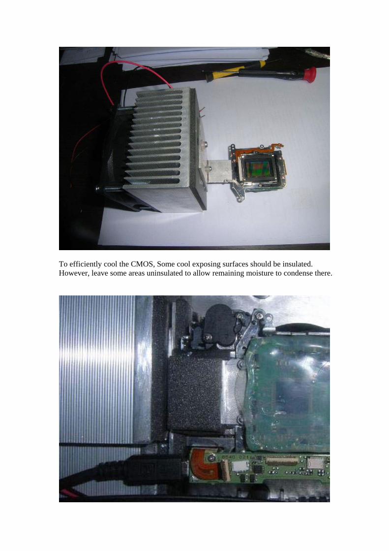
To efficiently cool the CMOS, Some cool exposing surfaces should be insulated. However, leave some areas uninsulated to allow remaining moisture to condense there.
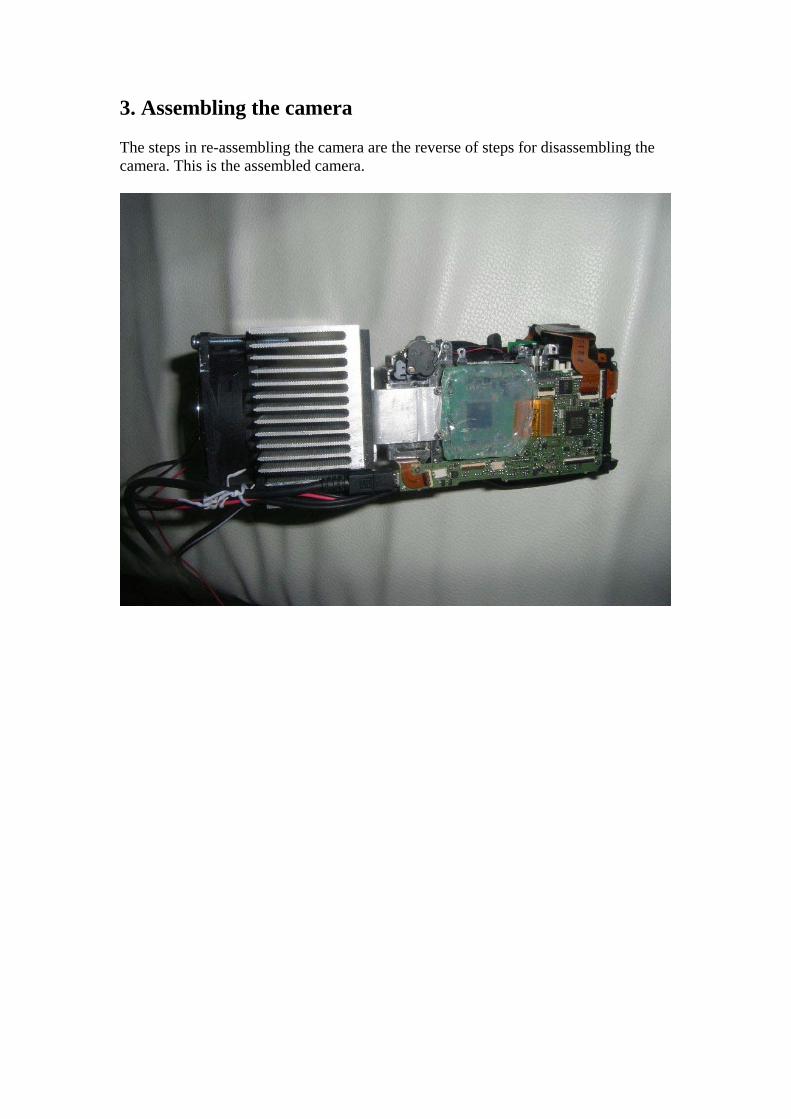
3. Assembling the camera The steps in re-assembling the camera are the reverse of steps for disassembling the camera. This is the assembled camera.
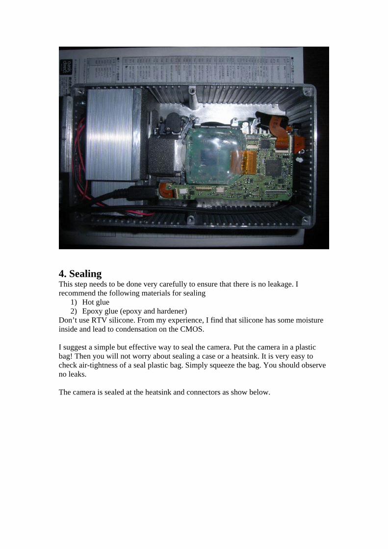
4. Sealing This step needs to be done very carefully to ensure that there is no leakage. I recommend the following materials for sealing
1) Hot glue 2) Epoxy glue (epoxy and hardener)
Don’t use RTV silicone. From my experience, I find that silicone has some moisture inside and lead to condensation on the CMOS. I suggest a simple but effective way to seal the camera. Put the camera in a plastic bag! Then you will not worry about sealing a case or a heatsink. It is very easy to check air-tightness of a seal plastic bag. Simply squeeze the bag. You should observe no leaks. The camera is sealed at the heatsink and connectors as show below.
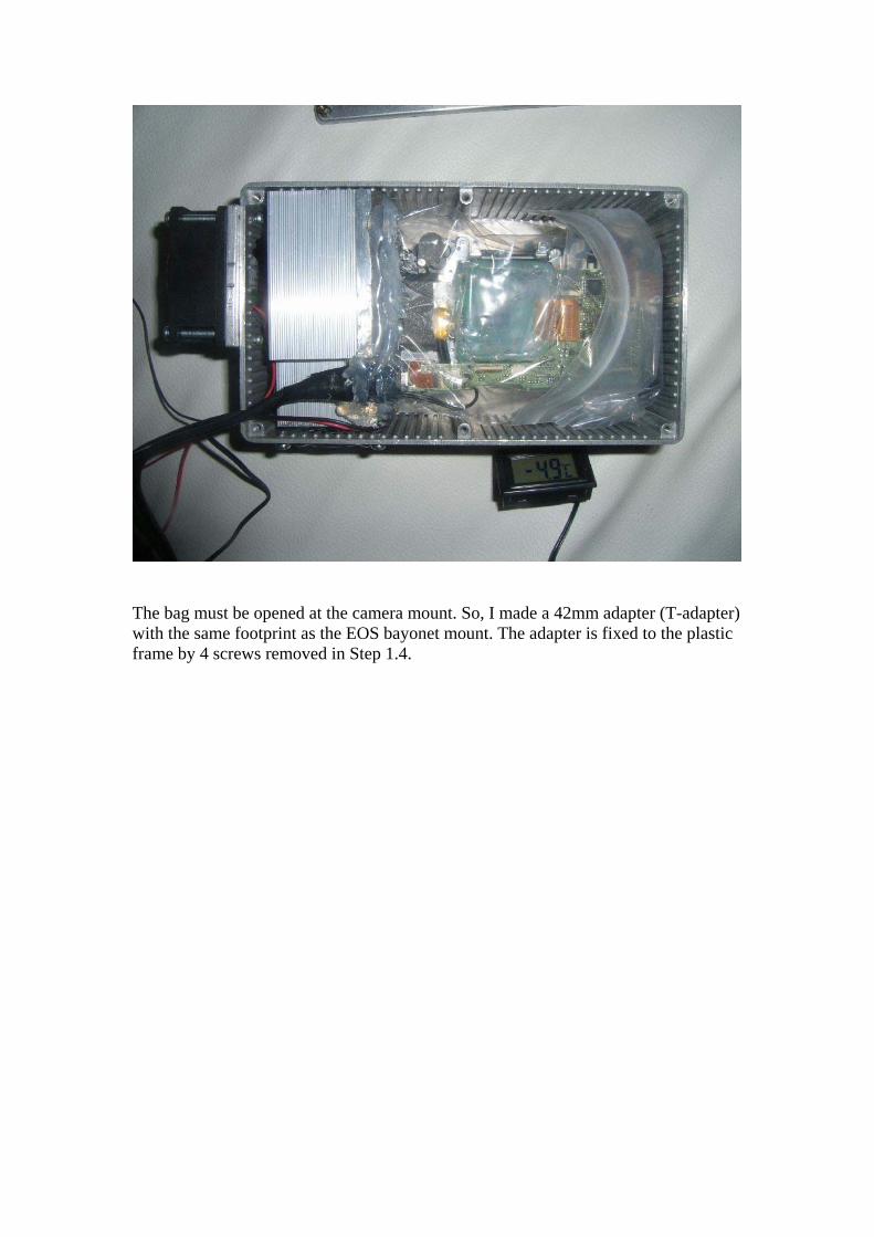
The bag must be opened at the camera mount. So, I made a 42mm adapter (T-adapter) with the same footprint as the EOS bayonet mount. The adapter is fixed to the plastic frame by 4 screws removed in Step 1.4.
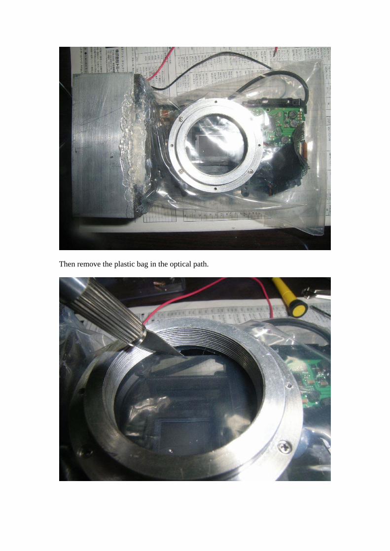
Then remove the plastic bag in the optical path.
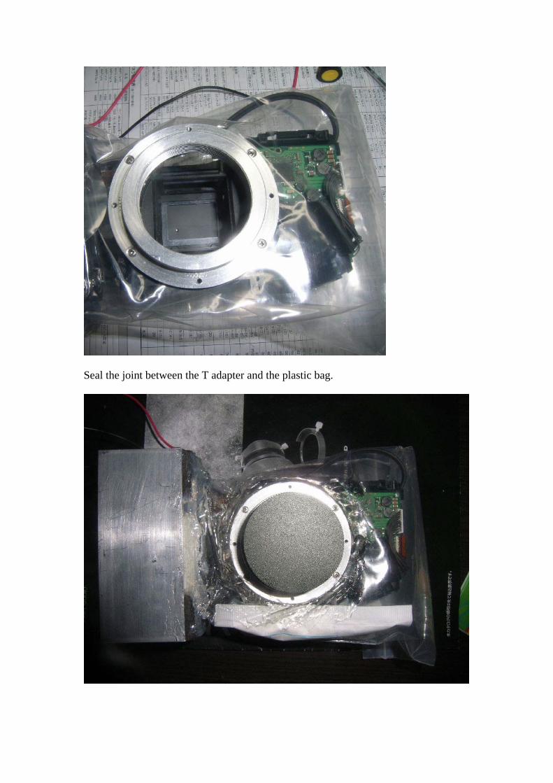
Seal the joint between the T adapter and the plastic bag.
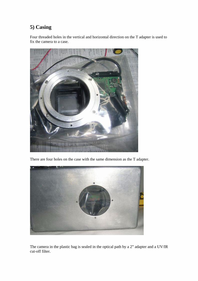
5) Casing Four threaded holes in the vertical and horizontal direction on the T adapter is used to fix the camera to a case.
There are four holes on the case with the same dimension as the T adapter.
The camera in the plastic bag is sealed in the optical path by a 2” adapter and a UV/IR cut-off filter.
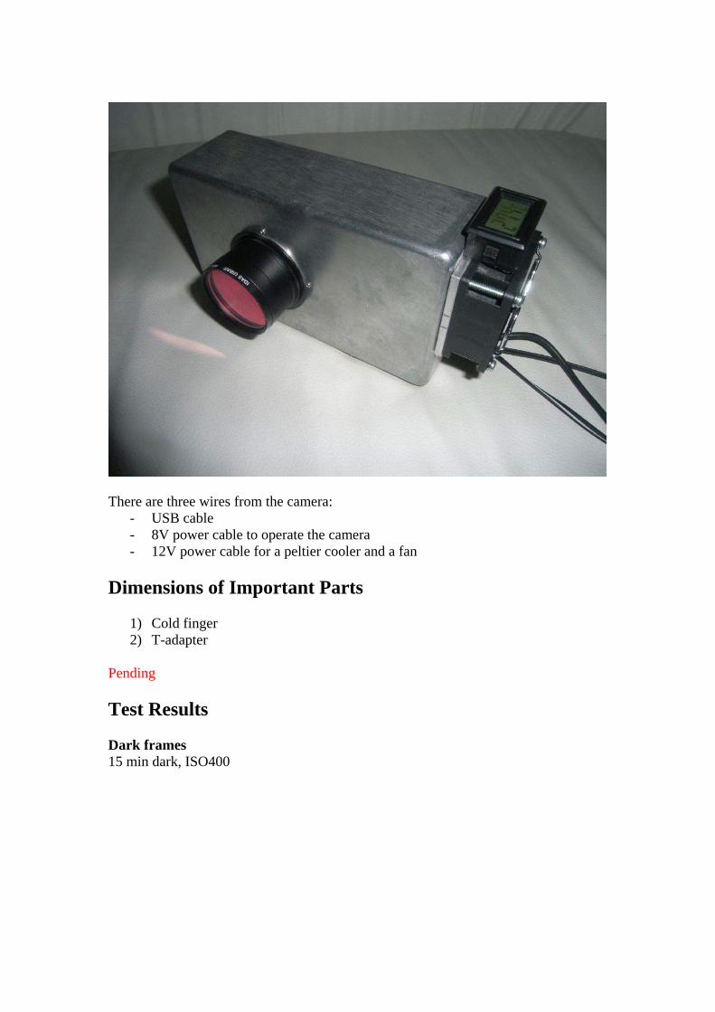
There are three wires from the camera:
- USB cable - 8V power cable to operate the camera - 12V power cable for a peltier cooler and a fan
Dimensions of Important Parts
1) Cold finger 2) T-adapter
Pending Test Results Dark frames 15 min dark, ISO400
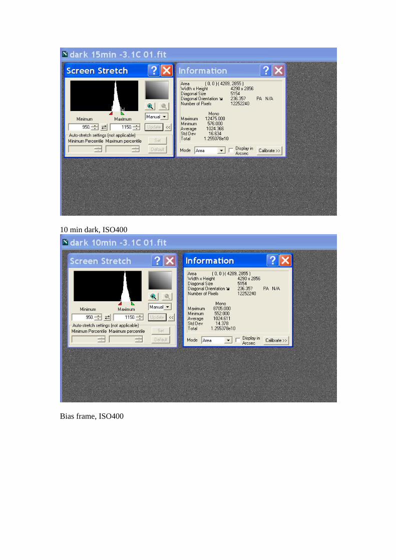
10 min dark, ISO400
Bias frame, ISO400
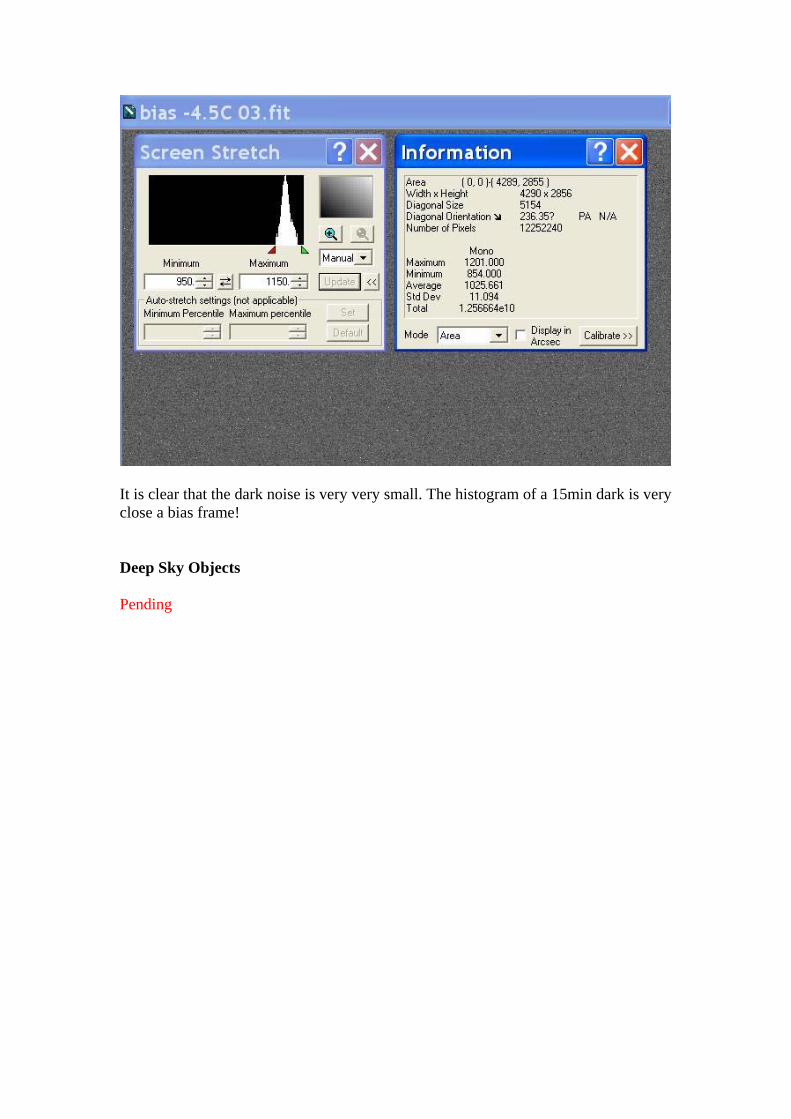
It is clear that the dark noise is very very small. The histogram of a 15min dark is very close a bias frame! Deep Sky Objects Pending