Hydrophilic electrospun polyurethane nanofiber matrices for hMSC culture in a microfluidic cell chip
10
Review Hydrophilic electrospun polyurethane nanofiber matrices for hMSC culture in a microfluidic cell chip Kwang Ho Lee, 1 Gu Han Kwon, 1 Su Jung Shin, 1 Ju-Yeoul Baek, 1 Dong Keun Han, 2 Yongdoo Park, 3,4 Sang Hoon Lee 1 1 Department of Biomedical Engineering, College of Health Science, Korea University, Seoul, Korea 2 Biomaterials Research Center, Korea Institute of Science and Technology, Seoul, Korea 3 Department of Biomedical Engineering, College of Medicine, Korea University, Seoul, Korea 4 Korea Artificial Organ Center, Korea University, Seoul, Korea Received 2 July 2007; revised 12 January 2008; accepted 27 February 2008 Published online 10 June 2008 in Wiley InterScience (www.interscience.wiley.com). DOI: 10.1002/jbm.a.32059 Abstract: Mimicking cellular microenvironments by MEMS technology is one of the emerging research areas. Integrated biomimetic systems with nanofiber polymer networks and microfluidic chips were fabricated and cellular behaviors were observed by changing surface characteristics of nano- fibers and flow rates of microchannels. Modification of pol- yurethane nanofiber surfaces were achieved by grafting acrylic acid with plasma treatment and these nanofiber mat- rices were employed in a poly(dimethylsiloxane) based microfluidic chip. The surface characteristics of both electro- spun nanofiber matrices was evaluated by measuring con- tact angle, porosity, and chemical structure using attenuated total reflection-Fourier transform infrared spectrometry. Af- ter modification, a terminal carboxyl group formed on the nanofiber surface and the wettability increased significantly. Human MSCs were seeded on the nanofiber matrices and a morphological investigation with actin filament staining and scanning electron microscopy was performed. A prolif- eration test by WST-1 and Live/Dead assay were per- formed to investigate the cell culture environment. It was observed that the cells on the AA-grafted nanofibers spread and proliferate compared to untreated nanofibers. It has also shown that flow rates in the microchannels played an important role for cell proliferation (Sim et al., Lab Chip 2007;7:1775-1782). Integration of nanofiber matrices into the microchannels provides the useful tools for mimicking cel- lular microenvironments and elucidating basic questions of cell and ECM assembly and interactions. Ó 2008 Wiley Peri- odicals, Inc. J Biomed Mater Res 90A: 619–628, 2009 Key words: electrospun nanofiber; human mesenchymal stem cells; polyurethane; polydimethylsiloxane; cell chip INTRODUCTION Combination of MEMS technology with biology opens a new field from elucidating basic questions of biology to engineering tissues in vitro. 1 Especially, it has been widely studied in cell biology issues such as cellular behaviors and cell fate determination by fabricating biomimetic extracellular environments with micro sized structures using MEMS technol- ogy. 2 Patterning of ECM proteins by soft lithography give rise to the guidance cues for stem cell differen- tiation. 3 Gradient generation of growth factors in the microchannels is another example for enabling the monitoring cellular behaviors in vivo. 4 Fabrication of biomimetic microenvironments is one of the important issues in the current bio-MEMS research fields. Recently, diverse poly(dimethylsilox- ane) (PDMS) based microfluidic cell chips have been developed and broadly utilized as cell culture tool providing miniaturized versions of conventional labo- ratory techniques. In addition, such microfluidic envi- ronments are used to investigate cell-to-cell, cell-to- extracellular matrix (ECM) interactions, behaviors in vitro and to emulate in vivo situations. In these cell chips, most of the ECMs are bare PDMS or a surface Correspondence to: S.H. Lee; e-mail: [email protected] Contract grant sponsor: Ministry of Health and Welfare; contract grant number: 02-PJ3-PG6-EV10-0001 Contract grant sponsor: Korea Science and Engineering Foundation; contract grant number: K20601000002-07E0100- 00230 Ó 2008 Wiley Periodicals, Inc.
-
Upload
kwang-ho-lee -
Category
Documents
-
view
212 -
download
0
Transcript of Hydrophilic electrospun polyurethane nanofiber matrices for hMSC culture in a microfluidic cell chip

Review
Hydrophilic electrospun polyurethane nanofiber matrices for hMSCculture in a microfluidic cell chip
Kwang Ho Lee,1 Gu Han Kwon,1 Su Jung Shin,1 Ju-Yeoul Baek,1 Dong Keun Han,2 Yongdoo Park,3,4
Sang Hoon Lee11Department of Biomedical Engineering, College of Health Science, Korea University, Seoul, Korea2Biomaterials Research Center, Korea Institute of Science and Technology, Seoul, Korea3Department of Biomedical Engineering, College of Medicine, Korea University, Seoul, Korea4Korea Artificial Organ Center, Korea University, Seoul, Korea
Received 2 July 2007; revised 12 January 2008; accepted 27 February 2008Published online 10 June 2008 in Wiley InterScience (www.interscience.wiley.com). DOI: 10.1002/jbm.a.32059
Abstract: Mimicking cellular microenvironments by MEMStechnology is one of the emerging research areas. Integratedbiomimetic systems with nanofiber polymer networks andmicrofluidic chips were fabricated and cellular behaviorswere observed by changing surface characteristics of nano-fibers and flow rates of microchannels. Modification of pol-yurethane nanofiber surfaces were achieved by graftingacrylic acid with plasma treatment and these nanofiber mat-rices were employed in a poly(dimethylsiloxane) basedmicrofluidic chip. The surface characteristics of both electro-spun nanofiber matrices was evaluated by measuring con-tact angle, porosity, and chemical structure using attenuatedtotal reflection-Fourier transform infrared spectrometry. Af-ter modification, a terminal carboxyl group formed on thenanofiber surface and the wettability increased significantly.Human MSCs were seeded on the nanofiber matrices and a
morphological investigation with actin filament stainingand scanning electron microscopy was performed. A prolif-eration test by WST-1 and Live/Dead assay were per-formed to investigate the cell culture environment. It wasobserved that the cells on the AA-grafted nanofibers spreadand proliferate compared to untreated nanofibers. It hasalso shown that flow rates in the microchannels played animportant role for cell proliferation (Sim et al., Lab Chip2007;7:1775-1782). Integration of nanofiber matrices into themicrochannels provides the useful tools for mimicking cel-lular microenvironments and elucidating basic questions ofcell and ECM assembly and interactions. � 2008 Wiley Peri-odicals, Inc. J Biomed Mater Res 90A: 619–628, 2009
Key words: electrospun nanofiber; human mesenchymalstem cells; polyurethane; polydimethylsiloxane; cell chip
INTRODUCTION
Combination of MEMS technology with biologyopens a new field from elucidating basic questionsof biology to engineering tissues in vitro.1 Especially,it has been widely studied in cell biology issuessuch as cellular behaviors and cell fate determinationby fabricating biomimetic extracellular environments
with micro sized structures using MEMS technol-ogy.2 Patterning of ECM proteins by soft lithographygive rise to the guidance cues for stem cell differen-tiation.3 Gradient generation of growth factors in themicrochannels is another example for enabling themonitoring cellular behaviors in vivo.4
Fabrication of biomimetic microenvironments is oneof the important issues in the current bio-MEMSresearch fields. Recently, diverse poly(dimethylsilox-ane) (PDMS) based microfluidic cell chips have beendeveloped and broadly utilized as cell culture toolproviding miniaturized versions of conventional labo-ratory techniques. In addition, such microfluidic envi-ronments are used to investigate cell-to-cell, cell-to-extracellular matrix (ECM) interactions, behaviorsin vitro and to emulate in vivo situations. In these cellchips, most of the ECMs are bare PDMS or a surface
Correspondence to: S.H. Lee; e-mail: [email protected] grant sponsor: Ministry of Health and Welfare;
contract grant number: 02-PJ3-PG6-EV10-0001Contract grant sponsor: Korea Science and Engineering
Foundation; contract grant number: K20601000002-07E0100-00230
� 2008 Wiley Periodicals, Inc.

coated with proteins such as fibronectin, gelatin, andcollagen.5 Limited research has been performed on theincorporation of well-defined ECM for cell cultureinside the cell chips.6
Human mesenchymal stem cells (hMSCs) are mul-tipotent cells that can differentiate into a variety ofcell types and have many potential applications incell therapy and tissue engineering. Mesenchymalstem cells are embedded in bone marrow in ourbody and reside the special microenvironmentscalled stem cell niches. Microenvironments of stemcells are dominantly composed of nanofiber-basedextracellular matrix proteins such as collagen andlaminins. Mimicking microenvironments with sub-micron sized synthetic nanofiber can be achieved byfabricating various kinds of nanostructures.
To date, various kinds of electrospun nanofibermatrices (ENM) have been widely employed as ECMor scaffolds for cell culture and tissue engineering.Most of the ENMs include biodegradable and natu-rally occurring polymers such as fibrinogen,7 silk pro-tein,8 elastin-mimetic peptides,9 casein and lipaseenzymes,10 DNA,11 and collagen.12 The diameters ofthese polymer fibers range from a few tenths to hun-dreds of nanometers, resulting in a very high surfacearea-to-volume ratio. In addition, the high porosityfibrillar connective structure has long been observedto be important for cell attachment, proliferation,migration, and differentiation in tissue culture.13
Therefore, a combination of microfluidic technologyand ENM can provide a better cell culture environ-ment, thus mimicking the in vivo environment. More-over, the combined culture system enables both sidesof the cultured cells to be bathed by the culture me-dium through the integrated porous nanofiber matri-ces. To this end, the in vivo interactions that existbetween matrices in different organs such as the liver,kidney or lung can be realized. In spite of such bene-fits, few cases of microfluidic chips integrating nano-fiber matrices have been reported due to the difficultyin fabrication. Typically, the ENM has poor mechani-cal properties, which limits the handling of ENM andthe integration of ENM with microfluidic chip.14
The three-dimensional matrices integrated intoPDMS-based microfluidic chip may offer the multi-functional benefits from a microfluidic channels pro-viding effective transport and exchange of cell culturemedium for development of three-dimensional scaf-fold, which help cell to grow and provide the diffu-sion of nutrients, metabolites, and growth factors.
In our previous work, the feasibility of a cell chipemploying polyurethane (PU) ENM as ECM wasrepresented with hMSC culture on the chip.15 PUENM is nonbiodegradable and mechanically strongenough to be handled and such mechanical propertyenables PU ENM to be easily integrated into themicrofluidic chips.16 However, the cellular compati-
bility of PU ENM was not fully proven and theENM surface requires optimization in order to pro-vide a better cell environment.
In this study, we integrated the nondegradablePU-based nanofibers in the microfluidic systems formimicking vascularized tissues embedded in ECMnanofibers. By changing the hydrophobicity of PUENM by acrylic acid grafting, we could examine thediffusion effects of biomolecules in the biomimetictissue structures. This result demonstrated that thechange of surface characteristics modulate the stemcell adhesion and proliferation. Effects of fiber diam-eters and flows rates in microchannels on stem cellproliferation and differentiation will be one of thechallenging issues in bio-MEMS.
MATERIALS AND METHODS
Cell chip fabrication
The PDMS-based cell chip, in which AA-grafted ENMwere integrated as ECM, was fabricated and its 3D sche-matics is shown in Figure 1. The cell chip consisted of two
Figure 1. Schemes of cell chip integrated with electro-spun nanofiber matrix; (a) diagonal view of designedchips, (b) picture of fabricated chip with PDMS. [Color fig-ure can be viewed in the online issue, which is available atwww.interscience.wiley.com.]
620 LEE ET AL.
Journal of Biomedical Materials Research Part A

layers (lower: microfluidic channel, upper: cell culturechamber), which were fabricated by the standard PDMSprocess17 and the ENM was incorporated between thelayers. The cell chip was assembled by the following pro-cedure: (1) the lower layer was produced by a SU-8 repli-cation mold, as reported previously, and the upper layerwas fabricated by hole punching the PDMS layer (thick-ness: 8 mm), (2) to bond the layers to the ENM, the surfaceof both PDMS layers was exposed to oxygen plasma for30 s to improve adhesion and the prepared nanofiber ma-trix was uniformly placed on the plasma-treated lowerlayer, and (3) the lower layer with ENM was bonded tothe upper layer and cured on a hot plate at 808C for 2 hby pressing at �0.89 kg/cm2.
Preparation of nanofiber matrix
The nanofiber matrix was prepared by electrospinningpolyurethane (PU, Pellethane 2363-80AE, Dow Chemical Co.)solution, which has a urethane group (ANHCOOA). PU wasdissolved in N, N-dimethylformamide (DMF, Aldrich, Mil-waukee, WI) and tetrahydrofuran (THF, Aldrich) with a 50/50 (v/v) ratio. The prepared PU solution was electrospunusing the electrospinning apparatus (Chungpa EMT Co.,Korea). The detailed optimum production-conditions for theformation of a good nanofiber matrix were reported previ-ously.18,19 Under these conditions, a positively charged PUsolution jet was formed from the Taylor cone and sprayed toa grounded collection drum wound with aluminum foil forthe facile removal of nanofiber matrix. After evaporation ofthe residual solvent, the matrices were dehydrated in a vac-uum oven at 608C for two days. The morphology of thenanofiber matrices was observed with SEM.
AA grafting by plasma treatment
The hydrophobic surface of the ENMs was hydrophi-cally modified by inducing carboxyl groups. To induceradicals on the ENM, plasma treatment was performedunder argon (Ar) gas and a hydrophilic AA monomer(Aldrich) with a radio frequency glow discharge (RFGD)device (PTS-003IDT, I.D.T. ENG., Inc., Korea).20 Theplasma treatment procedure is as follows; (1) the preparedENM was placed between the RFGD electrodes and thepressure of the reactor chamber was maintained below20 mTorr, (2) Ar gas was introduced into the reactionchamber for radical formation, (3) RF power (50 W) wasapplied to generate plasma for 1 min, (4) the AA monomerwas introduced for 2 min to induce carboxyl groups onthe ENM surface, and (5) the plasma treated ENM waspreserved under the isolation of humidity and light.
Porosity measurement of ENM
The ENM sample was cut to a weight of 0.03 g and theporosity was measured by a mercury intrusion porosimeter(AutoPore IV9520, Micromeritics) with a mercury filling pres-sure from 0.45 psi. The mercury porosimetry is based on thecapillary law governing liquid penetration into small spaces
and the analytical model, in the case of a non-wetting liquidlike mercury, is expressed by the Washburn equation21:
D ¼ 1
P
� �4g cos/
where D is the pore diameter, P is the applied pressure, gthe surface tension of mercury and / the contact anglebetween the mercury and sample.
Contact angle measurement
Wettability of the control group and AA-grafted ENMwas examined with static contact angle. The contact angleswere measured using a goniometer (Kruiss, G-23). Fivespecimens were prepared for each group and 5 lL of dis-tilled water was applied to each ENM surface. The dropletimages were captured by a CCD camera, analyzed by aPC, and the mean contact angles were calculated.
ATR-FTIR analysis
To qualitatively analyze the AA-grafted surfaces, Atte-nuated Total Reflection Fourier Transform Infrared (ATR-FTIR) analysis was performed using a Jasco 615 FTIR spec-trometer (JASCO Co., Japan). The control and AA-graftedENM specimens were cut to 1 3 1 cm sample size and thefrequency range was from 400 to 4000 cm21 with a 4 cm21
resolution. The measurements were performed within 1–2 h after plasma treatment and the specimens were storedin a vacuum drier before analysis.
Diffusivity measurement of ENM
The relative diffusivities of treated and un-treated ENMwere measured by using the high speed camera (PhotronFastcam PCI R2, Motion Engineering, USA) and Photoshop7.0 (Adobe Systems, Inc.) For measurement, we droppedthe colored water [with blue dye (Eastwell, Co., Ltd.)] onthe treated and untreated ENM surface and we took pic-tures of diffusing behavior with the frame rate of 300frames per second (fps). The captured images were ana-lyzed by the Photoshop 7.0 and the mean diffusion veloc-ities of both specimens were measured.
Observation of diffusion in chip
The biological materials or chemicals beneath the ENM-integrated in the cell culture chip can diffuse through theENM and will effect to cells growing on the surface ofENM. Here we have observed the diffusion and spreadingof rhodamine B (Aldrich) flowing beneath ENM and thechip including un-treated ENM was prepared as control.For the experiment, the culture media mixed with rhoda-mine B was introduced with different flow rate (0.5 mL/hand 1.0 mL/h) using syringe pump. Then, the fluorescenceon ENM will change and we have measured the fluores-cence on both the treated and un-treated membranes using
NANOFIBER MATRICES IN A MICROFLUIDIC CELL CHIP 621
Journal of Biomedical Materials Research Part A

a fluorescence microscope (Axiovert 200 M, Carl Zeiss,Germany) to investigate the perfusion property.
Cell culture
Human MSCs were obtained by aspiration from thebone marrow (BM) of healthy donors who gave theirinformed consent (Korea University Hospital, Anam). ThehMSCs were cultured at 378C under 5% CO2 in Dulbecco’sModified Eagle Medium (DMEM, GIBCO) supplementedwith 10% fetal bovine serum (FBS, GIBCO) and 5% antibi-otics (GIBCO) containing 10,000 units of penicillin andstreptomycin. The cells used were from the third to fourthpassages. For the preparation, the cells were washed with10 mL phosphate-buffered saline (PBS, pH 7.4, GIBCO) fortwo min. Residual PBS buffer was removed by carefulpipetting and the proliferated cells were detached by 2 mLof 0.05% EDTA-trypsin (incubation time: two min). Thedetached cells were diluted with 10 mL DMEM and centri-fuged at 1300 rpm for 5 min. The hMSCs (3 3 104) wereseeded on the untreated and AA-grafted ENMs and cul-tured in a CO2 incubator. The culture medium waschanged every two days.
Actin filament staining assay
For the morphological analysis of cultured cells, theactin filaments of cultured hMSCs were stained with AlexaFluor 568 phalloidin (Molecular Probes, Invitrogen)fluorescent dye. To improve the signal-to-noise ratio offluorescently labeled cells, Image-iTTM FX signal enhancer(Molecular Probes, Invitrogen) was applied and the back-ground noise was blocked by preventing nonspecific stain-ing. The fluorescent images were taken and processedwith an Axiover 200 M (Carl Zeiss, Germany) microscope.
Morphology analysis by SEM
The morphology of hMSCs on ENM was investigatedusing SEM (S-4700, Hitachi Co., Japan). Human MSCs cul-tured on the ENM were fixed with 4% formaldehyde(Electron Microscopy Sciences, Fort Washington, PA) inPBS for 1 h and rinsed three times with PBS. The speci-mens were dehydrated with ethanol and sputter-coatedwith gold for SEM observation.
Cell proliferation assay
The quantitative investigation of cell proliferation wascarried out by using cell proliferation reagent WST-1(Roche).22 WST-1 test is a colorimetric assay that is basedon mitochondrial dehydrogenase in viable cells.23 For theassay, ENM containing cultured hMSCs was rinsed twicewith PBS and a WST-1 solution (0.08 mL WST-1 containingin 0.8 mL DMEM low glucose) was applied. These WST-1treated cells on the ENM were incubated at 378C under5% CO2 for 1 h. The optical density was measured at a ref-
erence wavelength of 450 nm using an ELISA (MultiskanEx., Thermo Labsystems).
Live and dead assay
For the viability test, cells were treated with Live/Deadassay reagents (LIVE/DEAD1 Viability/Cytotoxicity Kit,Molecular Probe) and incubated for 10 min at room tem-perature. The viability of labeled cells was evaluated witha fluorescence microscope.
Cell culture in cell chip
For the feasibility test, hMSCs were seeded on cell chipswith AA-grafted ECM and incubated at 378C under 5%CO2 for five days. The culture medium was changed everytwo days. After incubation, the morphology of the cellswas investigated by actin filament staining with fluores-cent microscopy.
RESULTS AND DISCUSSION
Electrospinning of the nanofiber matrix
Under the predetermined electrospinning condi-tions (solution concentration: 12 wt %, solution flowrate: 0.5 mL/min, tip-to-collector distance: 7 cm, depo-sition time: 4 h, and electric field strength: 11 kV),24
the ENMs having uniform nanofiber diameter weresuccessfully produced without droplets, as illustratedby the SEM image of Figure 2(b,c). The randomly ori-ented, nanofiber diameter was 200–500 nm and interfiber pores were uniformly formed throughout themembrane and the size of inter fiber pores was �5–10 lm. In nonepithelial tissues, collagen triplestranded helix structure forms the collagen fibrils with50–200 nm diameters. Comparing to the natural nano-fiber structures, the nanofiber fabricated for this sys-tem is little thicker. However, considering the networkstructures and cross-linking densities in the nonepithe-lial tissues, this polymer network structure can beused for mimicking ECM networks. For investigatingfluid diffusion, porous structures with 5–10 lm couldalso be as cell culture model matrices for cell adhe-sion, migration and perfusion of nutrients or oxygen.
Changing surface characteristics of ENM bygrafting acrylic acid
The interesting feature of polyurethane in thebody is anti-adhesive for proteins. We modified thesurface characteristics of ENM by grafting acrylicacid for cell favor environments. The chemical struc-ture of untreated and AA-grafted ENM surfaces wasanalyzed by ATR-FTIR. As illustrated by Figure 2(a),
622 LEE ET AL.
Journal of Biomedical Materials Research Part A
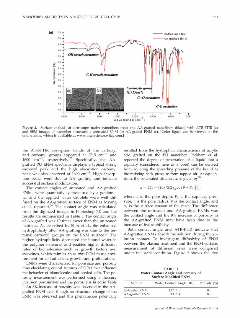
the ATR-FTIR absorption bands of the carboxyland carbonyl groups appeared at 1715 cm21 and1600 cm21, respectively.25 Specifically, the AA-grafted PU ENM spectrum displays a typical strongcarboxyl peak and the high absorption carbonylpeak was also observed at 1600 cm21. High absorp-tion peaks were due to AA grafting and indicatesuccessful surface modification.
The contact angles of untreated and AA-graftedENMs were quantitatively measured by a goniome-ter and the applied water droplets were well dif-fused on the AA-grafted surface of ENM as Myunget al. reported.26 The contact angle was calculatedfrom the digitized images in Photoshop 7.0 and theresults are summarized in Table I. The contact angleof AA-grafted was 10 times lower than the untreatedmatrices. As described by Shin et al., the enhancedhydrophilicity after AA grafting was due to the ter-minal carboxyl groups on the ENM surface.27 Thehigher hydrophilicity decreased the bound water inthe polymer networks and enables higher diffusionrates of biomolecules such as growth factors andcytokines, which mimics an in vivo ECM tissue envi-ronment for cell adhesion, growth and proliferation.
ENMs were characterized for pore size and porositythus elucidating critical features of ECM that influencethe behavior of biomolecules and seeded cells. The po-rosity measurement was performed using a mercuryintrusion porosimeter and the porosity is listed in TableI. An 8% increase of porosity was observed in the AA-grafted ENM even though no structural change of theENM was observed and this phenomenon potentially
resulted from the hydrophilic characteristics of acrylicacid grafted on the PU nanofiber. Packham et al.reported the degree of penetration of a liquid into acapillary (considered here as a pore) can be derivedfrom equating the spreading pressure of the liquid tothe resisting back pressure from tapped air. At equilib-rium, the penetrated distance, x, is given by28:
x ¼ Lð1� fPar=2½2g2 cos uþ Par�gÞ;
where L is the pore depth, Pa is the capillary pres-sure, r is the pore radius, u is the contact angle, andg2 is the surface tension of the resin. The differencebetween the untreated and AA-grafted ENMs wasthe contact angle and the 8% increase of porosity inthe AA-grafted ENM may have been due to theincrease of hydrophilicity.
Both contact angle and ATR-FTIR indicate thatAA-grafted ENMs absorb the solution during the so-lution contact. To investigate diffusivity of ENMbetween the plasma treatment and the ENM surface,measurement of diffusion rates were comparedunder the static condition. Figure 3 shows the dye
Figure 2. Surface analysis of elctrosupn native nanofibers (red) and AA-grafted nanofibers (black) with ATR-FTIR (a)and SEM images of nanofiber structures ; untreated ENM (b) AA-grated ENM (c). [Color figure can be viewed in theonline issue, which is available at www.interscience.wiley.com.]
TABLE IWater Contact Angle and Porosity of
Surface-Modified ENM
Sample Water Contact Angle (108) Porosity (%)
Untreated ENM 127 6 3 80AA-grafted ENM 13 6 4 88
NANOFIBER MATRICES IN A MICROFLUIDIC CELL CHIP 623
Journal of Biomedical Materials Research Part A

droplet after adsorption spreads rapidly in the AA-grafted ENM. Compared to the untreated ENM, thediffusivity was remarkably increased due to inducedhigher hydrophilicity. This result showed that diffu-sivity of ENM in cell culture onto ENM was practi-cally important of surface property. It can be postu-lated that cell adhesion occurred at the surface ofnanofibers because proteins adsorbed dominantly onthe AA-grafted nanofibers compared to the normalPU surfaces, which facilitate the cell adhesion andproliferations.
Figure 4 shows that the experimental flow and sat-uration profiles agree reasonably well with Figure 3for surface diffusion control in the cell chip. Theexperiment diffusivities depended on the hydrophi-licity of the ENM. The saturation time of fluores-cence was very rapid as the hydrophilicity of surfaceand flow rate of microchannels increase. The AA-grafted ENM and higher flow rate showed largestvalue. The reason may be due to the affinity betweenthe dye molecules and the surface of ENM by car-boxylic group. These results may suggest that diffu-sion of media molecules is controllable by surfacemodification of ENM in the cell chip.
Figure 3. Relative diffusivities of water on untreated andAA-grated ENM in the static condition. [Color figure canbe viewed in the online issue, which is available atwww.interscience.wiley.com.]
Figure 4. The comparison of diffusion rates under the different flow conditions; the fluorescence images of diffused rho-damine B solutions (1 mg/ml) through the untreated and AA-grafted nanofiber meshed with thickness (35 lm) (a). Mea-surement of fluorescence intensity on untreated and AA-grafted ENM depending on the flow rate with 0.5 ml/hr (b) and1.0 ml/hr (c). [Color figure can be viewed in the online issue, which is available at www.interscience.wiley.com.]
624 LEE ET AL.
Journal of Biomedical Materials Research Part A

Characteristics as ECM
As described previously, AA-grafted ENMshowed the potential to provide a better environ-ment for cell culture. Herein, the influence of surfacemodification on the hMSCs cultured on ENM wasinvestigated by morphological observation andquantitative measurement of proliferation and viabil-ity of bone marrow derived stem cells.
After five days of hMSCs culture on the untreatedand AA-grafted ENMs, the morphological changes ofstem cells were investigated with actin filament stain-ing and fluorescence imaging, as shown in Figure5(c,f). The cellular morphology on untreated ENMappears to be mostly localized and nonproliferatedalong the seeding framework. Alternatively, cellularmorphology on AA-grafted surface appeared to bewidely spread with the cytoskeleton framework ofthe cell. SEM was used to observe the morphologicaldifferences more clearly. Figure 5(a,b,d,e) illustratesSEM images of the hMSCs cultured on untreated andAA-grafted ENMs and the surface area of theattached hMSCs was calculated, as shown in Figure6. As expected from the actin filament staining, thedifferent surface conditions have a close relation withthe cell proliferation and orientation of protrusion.Remarkably, compared to the untreated ENM,hMSCs on the AA-grafted ENM displayed extendedfilopodia protrusions along the nanofibers and morecells were proliferated. Additionally, the cells on AA-grafted ENM illustrated more tendencies to migrateinto the pores, as reported by other researchers.29,30
The relative rate of hMSC proliferation was eval-uated bymitochondrial activity using theWST-1 kit. Fig-ure 7 shows the cellular activity on the untreated andAA-grafted ENMs and the control group was ENMwithout cells. There was a 30% difference of enzyme ac-tivity between the untreated and AA-grafted ENMs cul-tured with hMSCs after five days’ culture. Therefore, thehydrophilic ENM surface provided better conditionswith respect to cellular activity. Similarly, the viabilityof the cultured cells was measured, as summarized in
Figure 5. Cellular morphology of hMSCs cultured on the untreated (a–c) and AA-gratfted (d–f) surfaces. Cellular mor-phology was observed with SEM (a, b, d, and e) and actin filaments (c and f). [Color figure can be viewed in the onlineissue, which is available at www.interscience.wiley.com.]
Figure 6. Measurement of hMSC spreading on theuntreated and AA-grafted surfaces cultured for 5 days.Cell areas were measured from SEM images and cell areawas analyzed image processing software (LSM, Image Ex-aminer). [Color figure can be viewed in the online issue,which is available at www.interscience.wiley.com.]
NANOFIBER MATRICES IN A MICROFLUIDIC CELL CHIP 625
Journal of Biomedical Materials Research Part A

Figure 8. The mean viability of hMSCs on the untreatedENM was 586 5% and AA-grafted ENMwas 836 5%,corroborating actin filament staining.
These are several possible reasons for the bettercytocompatibility of AA-grafted ENM and one of thekey cues is the permeability. It is well known thatthe permeability of biological tissues and tissue-engi-neered scaffolds plays a significant role in the nutri-ent and waste transport within the structure.31 Thehydrophilicity of the material is closely related to thepermeability and the improved hydrophilicityaffected the cell growth and proliferation.
Cell chip with AA-grafted ENM
As shown in Figure 1, the PDMS-based cell chipwith control and AA-grafted ENM was successfullyfabricated. The white area represents the stableintegration of ENM into the PDMS chip and no
leakage at the bonding interface was observedthroughout several experiments. Within the cellchamber, the cell suspension was loaded using amicropipette and new media was slowly suppliedthrough the media channel. The media diffusedthrough the matrix and supplied fresh nutrientsand oxygen. Figure 9 shows the actin filamentstaining images of cells cultured on the chips forfive days. Cells on the AA-grafted ENM were pro-liferated well than the control ENM. To this end,the feasibility of perfusion cell chips with AA-grafted matrix as ECM has been proven and anarrayed cell chip which can provide multiple chem-icals simultaneously may soon be realized.
CONCLUSION
AA-grafting of PU ENM was effectively performedby plasma treatment and the surface modification wasconfirmed via various surface analyses. The AA-grafted hydrophilic ENM provided an excellent envi-ronment for cell growth and proliferation. The cellularstudy revealed that the AA-grafted PU ENM surfacegreatly promoted the hMSC adhesion, migration, andproliferation without affecting the desired bulk prop-erties of the ENM-ECM structure. A PDMS-based cellchip with AA-grafted PU ENM closely mimicking thein vivo environment was successfully fabricated byemulating the perfusion conditions and evaluatingthe feasibility of hMSC culture. In the perfusion chip,the nutrients, growth factors or other materials can besupplied to the cells from all directions and a morebiomimetic cell culture environment can be provided.To this end, on the basis of this technology, anarrayed cell chip for high-throughput screening of
Figure 8. The viability test of hMSCs cultured on the untreated (b), and AA-grafted (c). [Color figure can be viewed inthe online issue, which is available at www.interscience.wiley.com.]
Figure 7. Comparison of cellular proliferation culturedon ENM (untreated and AA-grafted) for 5 days. [Colorfigure can be viewed in the online issue, which is availableat www.interscience.wiley.com.]
626 LEE ET AL.
Journal of Biomedical Materials Research Part A

drugs can be realized. In addition, a cell chip combin-ing perfusion and matrices could be used as anin vitro tissue model to study basic dynamic features.
References
1. Voskerician G, Shive MS, Shawgo RS, Recum H, AndersonJM, Cima MJ, Langer R. Biocompatibility and biofouling ofMEMS drug delivery devices. Biomaterials 2003;24:1959–1967.
2. Tsang VL, Bhatia SN. Three-dimensional tissue fabrication.Adv Drug Deliv Rev 2004;56:1635–1647.
3. Thery M, Racine V, Pepin A, Piel M, Chen Y, Sibarita JB, Bor-nens M. The extracellular matrix guides the orientation of thecell division axis. Nat Cell Biol 2005;7:947–957.
4. Hung PJ, Lee PJ, Sabounchi P, Lin R, Lee LP. Continuousperfusion microfluidic cell culture array for high-throughputcell-based assays. Biotechnol Bioeng 2005;89:1–8.
5. Li N, Tourovskaia A, Folch A. Biology on a chip: Microfabri-cation for studying the behavior of cultured cells. Crit RevBiomed Eng 2003;31:423–488.
6. Ling Y, Rubin J, Deng Y, Huang C, Demirci U, Karp JM,Khademhosseini A. A cell-laden microfluidic hydrogel. LabChip 2007;7:756–762.
7. McManus MC, Boland ED, Simpson DG, Barnes CP, BowlinGL. Electrospun fibrinogen: Feasibility as a tissue engineeringscaffold in a rat cell culture model. J Biomed Mater Res A2006;81:299–309.
8. Meinel L. Hofmann S. Karageorgiou V, Zichner L, Langer R,Kaplan D, Vunjak-Novakovic G. Engineering cartilage-liketissue using human mesenchymal stem cells and silk proteinscaffolds. Biotechnol Bioeng 2004;88:379–391.
9. Ma Z, Kotaki M, Inai R, Ramakrishna S. Potential of nano-fiber matrix as tissue-engineering scaffolds. Tissue Eng 2005;11:101–109.
10. Xie J, Hsieh YL. Ultra-high surface fibrous membranes fromelectrospinning of natural proteins: Casein and lipaseenzyme. J Mater Sci 2003;38:2125–2133.
11. Funakoshi T, Majima T, Iwasaki N, Yamane S, Masuko T,Minami A, Harada K, Tamura H, Tokura S, Nishimura SI.Novel chitosan-based hyaluronan hybrid polymer fibers as ascaffold in ligament tissue engineering. J Biomed Mater ResA 2005;74:338–346.
12. Lee CR, Grodzinsky AJ, Spector M. Biosynthetic response ofpassaged chondrocytes in a type II collagen scaffold to me-chanical compression. J Biomed Mater Res A 2003;64:560–569.
13. Hosseinkhani H, Inatsugu Y, Hiraoka Y, Inoue S, ShimokawaH, Tabata Y. Impregnation of plasmid DNA into three-dimen-sional scaffolds and medium perfusion enhance in vitro DNAexpression of mesenchymal stem cells. Tissue Eng 2005;11:1459–1475.
14. Kim GH, Kim WD. Highly porous 3D nanofiber scaffoldusing an electrospinning technique. J Biomed Mater Res B2006;81:104–110.
15. Kim SR, Lee KH, Lee KH, Baek JY, Park TD, Sun K, Lee SH.Microfludic cell culture chip employing polymeric nanofibermembrane. In: proceedings of the 10th International Confer-ence on Miniaturized Systems for Chemistry and Life, 2006.p 1387–1390.
16. Lee KH, Kim DJ, Min BG, Lee SH. Polymeric nanofiber web-based artificial renal microfluidic chip. Biomed Microdevices2007;9:435–442.
17. Oh HJ, Kim SH, Baek JY, Seong GH, Lee SH. Hydrody-namic micro-encapsulation of aqueous fluids and cells via‘on the fly’ photopolymerization. J Micromech Microeng2006;16:285–291.
18. Lee KH, Kim DJ, Min BG, Lee SH. Nano web based novelmicrochip for artificial kidney. In: Proceedings of the WorldCongress 2006 on Medical Physics and Biomedical Engineer-ing, 2007. p 274–277.
19. Lee CH, Shin HJ, Cho IH, Kang YM, Kim IA, Park KD, ShinJW. Nanofiber alignment and direction of mechanical strainaffect the ECM production of human ACL fibroblast. Bioma-terials 2005;26:1261–1270.
20. Park K, Ju YM, Son JS, Ahn KD, Han DK. Surface modifica-tion of biodegradable electrospun nanofiber scaffolds andtheir interaction with fibroblasts. J Biomater Sci Polym Ed2007;18:369–382.
21. Jena A, Gupta K. Pore volume of nanofiber nonwovens. IntNonwovens J 2005;14:25–30.
22. Lamensdorf I, Eisenhofer G, Harvey-White J, Hayakawa Y,Kirk K, Kopin IJ. Metabolic stress in PC 12 cells induces theformation of the endogenous dopaminergic neurotoxin, 3,4-dihydroxypenylacetaldehyde. J Neurosci Res 2000;60:552–558.
23. Li WT, Chen HL, Wang CT. Effect of light emitting diodeirradiation of proliferation of human bone marrow mesenchy-mal stem cells. J Med Biol Eng 2005;26:35–42.
24. Lee KH, Kim JG, Kim DJ, Lee SH, Min BG. A novel artificialrenal microchip employing polymeric nanofibers membrane.In: Proceedings of the 10th International Conference onMiniaturized Systems for Chemistry and Life, 2006. p 1094–1097.
25. Ozdemir Y, Hasirci N. Oxygen plasma modification of polyur-ethane membrane. J Mater Sci Mater Med 2002;13:1147–1152.
Figure 9. The fluorescence images of actin filaments in hMSCs cultured on ENM incorporated inside cell chip; (a)untreated and (b) AA-grafted ENM based cell chip with 0.5 ml/hr flow rate. [Color figure can be viewed in the onlineissue, which is available at www.interscience.wiley.com.]
NANOFIBER MATRICES IN A MICROFLUIDIC CELL CHIP 627
Journal of Biomedical Materials Research Part A

26. Myung SW, Yeom YH, Jang YM, Choi HS. Preparation of areticulated polyurethane foam grafted with poly(acrylic acid)through atmospheric pressure plasma treatment and its lyso-zyme immobilization. J Mater Sci 2005;16:745–751.
27. Choi HS, Kim YS, Zhang Y, Tang S, Myung SW, Shin BC.Plasma-induced graft co-polymerization of acrylic acid ontothe polyurethane surface. Surf Coatings Technol 2004;182:55–64.
28. Packham DE. Physiochemical aspects of polymer surfaces. In:Mittal KL, editor. International Journal of Adhesion andAdhesive. New York: Plenum Press; 1983. p 583–594.
29. Venugopal J, Ramakrishna S. Biocompatible nanofiber matri-ces for the engineering of a dermal substitute for skin regen-eration. Tissue Eng 2005;11:847–854.
30. Lampin M, Warocquier-Clerout R, Legris C, Degrange M,Sigot-Luizard MF. Correlation between substratum roughnessand wettability cell adhesion and cell migration. J BiomedMater Res 1997;36:99–108.
31. O’Brien FJ, Harley BA, Waller MA, Yannas IV, Gibson LJ,Prendergast PJ. The effect of pore size on permeability andcell attachment in collagen scaffolds for tissue engineering.Technol Health Care 2007;15:3–17.
628 LEE ET AL.
Journal of Biomedical Materials Research Part A