HYDROGRAPHIC SURVEY OF Okmulgee Lake€¦ · Original Design and 2015 Survey ... Hypack’s...
23
HYDROGRAPHIC SURVEY OF OKMULGEE LAKE Final Report September 28, 2015 Prepared by:
Transcript of HYDROGRAPHIC SURVEY OF Okmulgee Lake€¦ · Original Design and 2015 Survey ... Hypack’s...

HYDROGRAPHIC SURVEY OF
OKMULGEE LAKE
Final Report
September 28, 2015
Prepared by:

2
TABLE OF CONTENTS
TABLE OF CONTENTS ............................................................................................................ 2 TABLE OF FIGURES ................................................................................................................ 3 TABLE OF TABLES .................................................................................................................. 3 INTRODUCTION ...................................................................................................................... 4
HYDROGRAPHIC SURVEYING PROCEDURES .................................................................. 6 Pre-Survey Planning .......................................................................................................... 6
Boundary File ................................................................................................................. 6 Set-up ............................................................................................................................. 6
Field Survey ....................................................................................................................... 6
Lake Elevation Acquisition ............................................................................................ 6 Method ........................................................................................................................... 7
Technology ..................................................................................................................... 7 Survey ............................................................................................................................ 7 Quality Assurance/Quality Control ................................................................................ 7
Data Processing ................................................................................................................ 10
GIS Application ............................................................................................................... 10 RESULTS ................................................................................................................................. 11 SUMMARY and COMPARISON ............................................................................................ 12
REFERENCES .......................................................................................................................... 13 APPENDIX A: Area-Capacity Data ........................................................................................ 14
APPENDIX B: Okmulgee Lake Maps ..................................................................................... 19

3
TABLE OF FIGURES
Figure 1: Location map for Okmulgee Lake. ............................................................................. 5 Figure 2: Digital Echogram of Okmulgee Lake barcheck. ........................................................ 9
Figure A- 1: Cumulative Capacity Curve for Okmulgee Lake. ............................................... 17
Figure A- 2: Cumulative Area Curve for Okmulgee Lake. ..................................................... 17
Figure B- 1: Okmulgee Lake Survey Track Lines. .................................................................. 20 Figure B- 2: Okmulgee Lake Bathymetric Map with 5-ft Contour Intervals. ......................... 21 Figure B- 3: Okmulgee Lake Shaded Relief Bathymetric Map. .............................................. 22
Figure B- 4: Okmulgee Lake Collected Data Points Map. ...................................................... 23
TABLE OF TABLES
Table 1: Summary of Relevant Minimum Performance Standards (MPS) and Quality
Assurance (QA) Practices for the Hydrographic Survey (USACE, 2002&2013). ............ 8
Table 2: Area and Volume of Okmulgee Lake at normal pool (690 ft NAVD88) for 1928
Original Design and 2015 Survey (OWRB, 1979). ......................................................... 12
Table A- 1: Okmulgee Lake Capacity by 0.1-ft Increments. ................................................... 15 Table A- 2: Okmulgee Lake Area by 0.1-ft Increments. ......................................................... 16

4
OKMULGEE LAKE
HYDROGRAPHIC SURVEY REPORT
INTRODUCTION
The Oklahoma Water Resources Board (OWRB) conducted a hydrographic survey of
Okmulgee Lake beginning on August 6, 2015. The purpose of this survey was to produce a
current elevation-area-capacity table for Okmulgee Lake to allow a volumetric determination
of dissolved oxygen beneficial use assessment.
Okmulgee Lake is located on a tributary of Salt Creek in Okmulgee County (Figure 1). The
dam was completed in 1928. Owned by the City of Okmulgee, the reservoir’s original
purposes were water supply and recreation. The dam is located in Sec. 08-T13N-R12E.

5
Figure 1: Location map for Okmulgee Lake.

6
HYDROGRAPHIC SURVEYING PROCEDURES
The process of surveying a reservoir uses a combination of Geographic Positioning System
(GPS) and acoustic depth sounding technologies that are incorporated into a hydrographic
survey vessel. As the survey vessel travels across the lake’s surface, the echosounder gathers
multiple depth readings every second. The depth readings are stored on the survey vessel’s
on-board computer along with the positional data generated from the vessel’s GPS receiver.
The collected data files are downloaded daily from the computer and brought to the office for
editing. During editing, data “noise” is removed or corrected, and depth readings are
converted to elevation readings based on the daily-recorded lake level elevation on the day the
survey was performed. The edited data sets are then thinned to manageable sizes using
Hypack’s “Sounding Selection-Sort Program” using a 1 ft sort radius. Using ArcGIS accurate
estimates of area-capacity can then be determined for the lake by building a 3-D model of the
reservoir from the sorted data set. The process of completing a hydrographic survey includes
four steps: pre-survey planning, field survey, data processing, and model construction.
Pre-Survey Planning Boundary File
The boundary for Okmulgee Lake was derived using 2-meter lidar data. A lidar raster file
(TIFF format) for the Okmulgee Lake and Beggs USGS 1:24,000 quadrangle was
downloaded from the Natural Resources Conservation Service (NRCS) Geospatial Data
Gateway website (https://gdg.sc.egov.usda.gov/). An NRCS tool developed for the ArcGIS
Spatial Analyst extension was used to generate contours from the lidar file. A lake boundary
line shapefile was created from the 690.0-ft contour, which is representative of normal pool
elevation for Okmulgee Lake. This line shapefile was edited in ArcGIS software using the
2013 USDA-FSA National Agriculture Imagery Program (NAIP) orthophoto mosaic for
Okmulgee County, Oklahoma, as a reference to ensure complete shoreline coverage. The
boundary was digitized in the NAD 1983 Oklahoma North State Plane coordinate system.
Set-up
Hypack software from Hypack, Inc. was used to assign geodetic parameters, import
background files, and create virtual track lines (transects). The geodetic parameters assigned
were ellipsoid World Geodetic System of 1984 (WGS-84) in State Plane North American
Datum of 1983 (NAD-83) Zone OK-3501 Oklahoma North. The distance and depth units used
were US Survey Feet. The vertical datum was set to the North American Vertical Datum of
1988 (NAVD88). The survey transects were spaced according to the accuracy required for the
project. The survey transects within the digitized reservoir boundary for Okmulgee were set
at 200 ft increments and ran perpendicular to the original stream channels and tributaries.
There were 104 virtual transects created for Okmulgee Lake. An additional 2 track lines set
perpendicular to the transect lines were added for cross check statistics.
Field Survey Lake Elevation Acquisition
The lake elevation for Okmulgee Lake was obtained by collecting positional data over a
period of 186 minutes. Data collection was done using a Trimble Zephyr Geodetic Antenna
connected to Trimble 5700 receiver, and controlled using Trimble TSCe survey controller.
7
This data was then uploaded to the On-line Positioning Users Service-Rapid Static (OPUS-
RS) website. The National Geodetic Survey (NGS) operates the OPUS as a means to provide
GPS users' easier access to the National Spatial Reference System (NSRS). OPUS-RS allows
users to submit their GPS data files to NGS, where the data is processed to determine a
position using NGS computers and software. Each data file that is submitted is processed
with respect to at least three Continuously Operating Reference Stations (CORS). All
collection and processing of elevation data followed methods covered in full detail in the
OWRB Standard Operating Procedures (SOP) for lake elevation measurement found in the
approved project Quality Assurance Project Plan (QAPP) (OWRB, 2015).
Method
The procedures followed by the OWRB during the hydrographic survey adhere to U.S. Army
Corps of Engineers (USACE) standards EM 1110-2-1003 (USACE, 2013) as stated in the
approved project QAPP (OWRB, 2015). The quality assurance and quality control (QA/QC)
procedures for equipment calibration and operation, field survey, data processing, and
accuracy standards are presented in the following sections and covered in more detail in the
approved project QAPP (OWRB, 2015).
Technology
The Hydro-survey vessel is an 18-ft aluminum hull with cabin, powered by a single 115-
horsepower outboard motor. Equipment used to conduct the survey included: a notebook
computer running Hypack’s 2014 survey data collection software; Innerspace 456 Echo
Sounder, with a depth resolution of 0.1 ft; Hemisphere R131 receiver with differential global
positioning system (DGPS) correction; and an Odom Hydrographics, Inc, DIGIBAR-Pro
Profiling Sound Velocimeter.
Survey
A two-man survey crew was used during the project. Data collection for Okmulgee Lake
occurred on August 6, 2015. The water level elevation for Okmulgee Lake was measured at
689.24 ft (NAVD88). Data collection began at the dam and moved upstream. The survey
crew followed the parallel transects created during the pre-survey planning while collecting
depth soundings and positional data. Data was also collected along a path parallel to the
shoreline at a distance that was determined by the depth of the water and the draft of the boat
– generally a depth of 3 to 5 ft. In areas of the lake that were too narrow for pre-planned
transect lines, a zigzag pattern was used to collect data. These areas included small tributaries
as well as the upstream section of the reservoir. Similar to the shoreline data collection
procedure, upstream data was collected until depths were too shallow for the boat to navigate.
Upstream data on the Salt Creek tributary was collected up to a fallen tree that prevented
access to the remainder of the creek.
Quality Assurance/Quality Control
The Okmulgee Lake hydrographic survey followed the quality control procedures presented
in the approved QAPP (OWRB, 2015) and summarized in Table 1. While on board the
Hydro-survey vessel, the Innerspace 456 Echo Sounder was calibrated using both a
DIGIBAR-Pro Profiling Sound Velocimeter and a bar check setup. The sound velocimeter
measures the speed of sound (SOS) at incremental depths throughout the water column. The
factors that influence the SOS—depth, temperature, and salinity—are all taken into account.

8
Deploying the unit involved lowering the probe, which measures the SOS, into the water to
the calibration depth mark to allow for acclimation and calibration of the depth sensor. The
unit was then gradually lowered at a controlled speed to a depth just above the lake bottom,
and then was raised to the surface. The unit collected sound velocity measurements in
feet/seconds (ft/sec) at 1 ft increments on both the deployment and retrieval phases. The data
was then reviewed for any erroneous readings, which were then edited out of the sample. The
sound velocity corrections were then applied to the raw depth readings during the editing
process using Hypack’s Sound Velocity tool. The mean SOS in the water column was
4860.76 ft/sec during the Okmulgee Lake survey. A bar check was performed using the mean
SOS and bar check setup to calibrate the echosounder. The bar check procedure adheres to
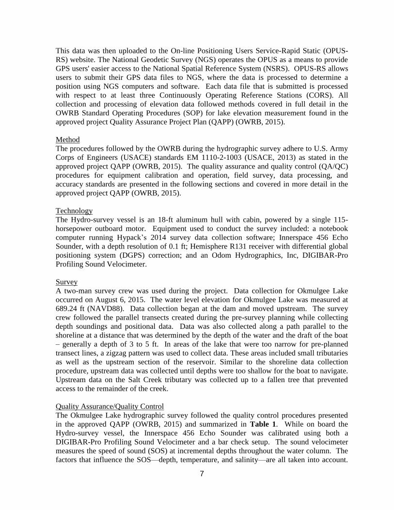
USACE methods (USACE, 2013). Figure 2 is the final Okmulgee Lake echogram showing
the bar check setup progressing in 5ft intervals from setting the draft to a maximum depth of
35 ft. The bar check yielded a final SOS setting of 4950 ft/sec and a static draft depth offset of
1.1 ft. Both settings were entered into the echo-sounder prior to survey sampling.
Table 1: Summary of Relevant Minimum Performance Standards (MPS) and Quality
Assurance (QA) Practices for the Hydrographic Survey (USACE, 2002&2013).
Minimum Performance Standards and Quality Assurance Practices for the Hydrographic Survey
Repeatability (Bias) 0.3 ft 0.5 ft
Standard Deviation (± ft at 95%) ± 0.8 ft
Resultant Elevation/Depth Accuracy (95%)(15>d<40 ft) ± 2.0 ft
Horizontal Positioning System Accuracy (95%) 5 m (16 ft)
Minimum Survey Coverage Density Not to Exceed 500 ft (150 m)
Quality Control and Assurance Criteria --
Bar Check 1/project
Sound Velocity QC calibration 2/day
Squat Test 1/year
Position calibration QC check 1/project
From the 2002 version of EM 1110-2-1003 From the 2013 version of EM 1110-2-1003
Depth observations contain both random errors (σ RANDOM ERROR) and systematic biases
(σ BIAS). Biases are often referred to as systematic or external errors and may contain
observational blunders. A constant error in tide or stage would be an example of a bias. Biases
are reduced as much a possible by using the quality control measures previously discussed.
Random errors are those errors present in the measurement system that cannot be easily
minimized by further calibration. Examples include echo sounder resolution, water sound
velocity variations, tide/staff gage reading resolution, etc. The precision of the observations is
a measure of the closeness of a set of measurements--or their internal agreement. Accuracy
relates to the closeness of measurements to their true or actual value
Accuracy and precision were assessed utilizing a cross-line check method referenced in the
approved QAPP (OWRB, 2015). The cross-line check was performed by collecting depth

9
readings along survey track lines perpendicular to, and intersecting the survey transect lines.
Hypack’s Cross Check Statistics program was used to assess vertical accuracy and confidence
measures of the recorded depths at the points where the lines intersected. This program
tabulated and statistically analyzed the depth differences between intersecting points of single
beam data. The program provides a report calculating the standard deviation and mean
difference. A total of 120 cross-sections points at Okmulgee Lake were used by the Cross
Check Statistics Program. A mean difference (Bias) of 0.061 ft was calculated, well below
both the 2002 and 2013 minimum performance standards (MPS). The standard deviation
(Random Error) for the survey was 1.034 ft from the intersecting points. While this does not
meet the 2013 MPS of 0.8 ft according to the USACE the difference is not significant due to
there being little to no bias (USACE, 2013).
Figure 2: Digital Echogram of Okmulgee Lake barcheck.
The mean difference and the standard deviation can then be used to calculate the Root Mean
Square (RMS) error employing the following calculation. The RMS error estimate is used to
compare relative accuracies of estimates that differ substantially in bias and precision
(USACE, 2002). According the recommended standards in the approved QAPP; the MPS at
the 95% confidence level should not exceed a tolerance of 2.0 ft for reservoir surveys
(Hydrography). This simply means that on average, 19 of every 20 observed depths will fall
within the specified accuracy tolerance.
BiaserrorRandomRMS 22
where:
Random error = standard deviation
Bias = mean difference
RMS = Root Mean Square error (68% confidence level)
and:
%)68(96.1%)95( RMSaccuracydepthRMS
An RMS of 2.0 ft with a 95% confidence level meets the QAPP’s MPS of 2.0 ft for
reservoir surveys.

10
The GPS system is an advanced high performance geographic data-acquisition tool that uses
differential GPS (DGPS) to provide sub-meter positional accuracy on a second-by-second
basis. Potential errors are reduced with DGPS because additional data from a reference GPS
receiver at a known position are used to correct positions obtained during the survey. Before
the survey, the settings on the Hemisphere R131 were checked to configure the GPS receiver.
To maximize the accuracy of the horizontal positioning, the horizontal mask setting was set to
6 degrees and the MaxDGPSAge was set to 300. The GGA and VTG were both set to 1 Hz.
The RTCM option was enabled with all other options disabled. The United States Coast
Guard reference station used in the survey is located near Sallisaw, Oklahoma.
A latency test was performed to determine the fixed delay time between the GPS and single
beam echo sounder. The timing delay was determined by running reciprocal survey lines over
a channel bank. The raw data files were downloaded into Hypack - LATENCY TEST
program. The program varies the time delay to determine the “best fit” setting. A position
latency of 0.4 seconds was produced and adjustments were applied to the raw data, Hypack’s
Single Beam Editor Program, during data processing.
Data Processing The collected data was transferred from the field computer onto an OWRB desktop computer.
After downloading the data, each raw data file was reviewed using the Single Beam Editor
program within Hypack. The Single Beam Editor program allowed the user to assign
transducer offsets, latency corrections, tide corrections, display the raw data profile, and
review/edit all raw depth information. Raw data files are checked for gross inaccuracies that
occur during data collection. Data editing is covered in more detail in the approved project
QAPP (OWRB, 2015).
Offset correction values of 3.2 ft. starboard, 6.6 ft. forward, and -1.3 ft vertical were applied
to all raw data along with a latency correction factor of 0.4 seconds. The SOS corrections
were applied during editing of raw data using the sound velocity corrections created using the
sound velocity tool.
A correction file was produced using the Hypack’s Manual Tides program to account for the
variance in lake elevation at the time of data collection. Within the Single Beam Editor
program, the corrected depths were subtracted from the elevation reading to convert the depth
in feet to an elevation. The measured elevation of the lake during the survey was 689.24 ft
(NAVD88).
After editing the data for errors and correcting the spatial attributes (offsets and tide
corrections), a data reduction scheme was needed due to the large quantity of collected data.
To accomplish this, the corrected data was sorted spatially at a 5 ft interval using the
Sounding Selection program in Hypack. The resultant data was saved and exported out as a
xyz.txt file. The Hypack raw and corrected data files for Okmulgee Lake will be stored and
made available upon request.
GIS Application Geographic Information Systems (GIS) software was used to process the edited XYZ data
collected from the survey. The GIS software used was ArcGIS Desktop, version 10.1, from

11
Environmental Systems Research Institute (ESRI). All of the GIS datasets created are in
Oklahoma State Plane North Coordinate System referenced to the North American Datum
1983. Horizontal and vertical units are in feet. The edited data points in XYZ text file format
were converted into a point feature class in an ArcGIS file geodatabase. The point feature
class contains the X and Y horizontal coordinates and the elevation and depth values
associated with each collected point.
Volumetric and area calculations were derived using a Triangulated Irregular Network (TIN)
surface model. The TIN model was created with ArcGIS using the collected survey data
points; 5-foot contours derived from a raster file interpolated from the collected survey data
points; and inputs representing the lake boundary at normal pool elevation. The TIN consists
of connected data points that form a network of triangles representing the bottom surface of
the lake. The lake volume was calculated by slicing the TIN horizontally into planes 0.1 ft
thick. The cumulative volume and area of each slice are shown in APPENDIX A: Area-
Capacity Data.
Contours, depth ranges, and the shaded relief map were derived from a constructed digital
elevation model grid. This grid was created using the ArcGIS Topo to Raster Tool and had a
spatial resolution of 1 ft. The contours were created at a 5 ft interval using the ArcGIS contour
tool.
The contour lines were edited to allow for polygon topology and to improve accuracy and
general smoothness of the lines. The contour lines were edited visually paying close attention
to the channel area, while also ensuring the lines matched the original data set. The contours
were then converted to a polygon feature class and attributed to show 5-ft depth ranges across
the lake. The bathymetric maps of the lakes are shown with 5-ft contour intervals in
APPENDIX B: Okmulgee Lake Maps.
All geographic datasets derived from the survey contain Federal Geographic Data Committee
(FGDC) compliant metadata documentation. The metadata describes the procedures and
commands used to create the datasets. The GIS metadata file for Okmulgee Lake is located
on the DVD entitled Okmulgee Hypack/GIS Metadata.
RESULTS
Results from the 2015 OWRB survey indicate that Okmulgee Lake encompasses 644.76 acres
and contains a cumulative capacity of 11,497.03 ac-ft at the normal pool elevation of 690 ft
(NAVD88). The mean depth for Okmulgee Lake was 17.83 ft.

12
SUMMARY and COMPARISON
Table 1 displays area and volume calculations of Okmulgee Lake at the normal pool
elevation for 1928 and 2015. Based on the design specifications, Okmulgee Lake had an area
of 668 acres and cumulative volume of 14,170 ac-ft of water at normal pool elevation (690 ft
NAVD88). The surface area of the lake has had a decrease of 23.24 acres or approximately
3.48%. The 2015 survey shows that Okmulgee Lake has an apparent decrease in capacity of
18.86% or approximately 2672.97 acre-feet. Caution should be used when directly comparing
between the design specifications and the 2015 survey conducted by the OWRB because
different methods were used to collect the data and extrapolate capacity and area. It is the
recommendation of the OWRB that another survey using the same method used in the 2015
survey be conducted in 10-15 years. By using the 2015 survey figures as a baseline, a future
survey would allow an accurate mean sedimentation rate to be obtained.
Table 2: Area and Volume of Okmulgee Lake at normal pool (690 ft NAVD88) for 1928
Original Design and 2015 Survey (OWRB, 1979).
Feature
Survey Year
1928
Design Specifications 2015
Area (acres) 668 644.76
Cumulative Volume (acre-feet) 14,170 11,497.03
Mean depth (ft) 21.2 17.83
Maximum Depth (ft) -- 55.4

13
REFERENCES
Oklahoma Water Resources Board (OWRB). 1979. Phase 1 Inspection Report; National
Dam Safety Program.
Oklahoma Water Resources Board (OWRB). 2015. Quality Assurance Project Plan for
Bathymetric Mapping of Selected Water Supply Reservoirs Impaired for Dissolved
Oxygen FY 14/15 Section 106 I-006400-14 Project 11. QTRAK #15-255
U.S. Army Corps of Engineers (USACE) (2002). Engineering and Design - Hydrographic
Surveying, Publication EM 1110-2-1003, 3rd
version.
U.S. Army Corps of Engineers (2002): Engineering Design: Hydrographic Surveying(EM
1110-2-1003); Chapter 3. Table 3-1: Minimum Performance Standards for Corps of
Engineers Hydrographic Surveys (Mandatory); Project Classification – Other General
Surveys & Studies.www1.frm.utn.edu.ar/laboratorio_hidraulica/Biblioteca_Virtual/Hydrographic%20Surveying/c-3.pdf
U.S. Army Corps of Engineers (2013).Engineering and Design: Hydrographic Surveying (EM
1110-2-1003). Available from www.publications.usace.army.mil/Portals/76/Publications/EngineerManuals/EM_1110-2-1003.pdf

14
APPENDIX A: Area-Capacity Data

Table A- 1: Okmulgee Lake Capacity by 0.1-ft Increments.
Okmulgee Lake Capacity Table
Volume in Acre-Feet by Tenth Ft Elevation Increments
2015 SURVEY
Oklahoma Water Resources Board
Elevation
in Feet 0.0 0.1 0.2 0.3 0.4 0.5 0.6 0.7 0.8 0.9
634 0.00 0.00 0.00 0.00
635 0.00 0.00 0.00 0.00 0.00 0.00 0.00 0.00 0.00 0.00
636 0.00 0.01 0.01 0.01 0.01 0.01 0.02 0.02 0.02 0.02
637 0.03 0.03 0.04 0.04 0.05 0.05 0.06 0.07 0.07 0.08
638 0.09 0.12 0.15 0.18 0.21 0.25 0.29 0.33 0.38 0.44
639 0.50 0.62 0.74 0.88 1.02 1.17 1.33 1.49 1.67 1.85
640 2.05 2.27 2.51 2.76 3.01 3.28 3.56 3.84 4.14 4.45
641 4.77 5.10 5.44 5.79 6.14 6.50 6.87 7.25 7.63 8.02
642 8.42 8.83 9.25 9.68 10.11 10.55 11.00 11.46 11.93 12.41
643 12.90 13.43 13.98 14.54 15.13 15.73 16.34 16.98 17.64 18.33
644 19.04 19.85 20.70 21.57 22.47 23.41 24.38 25.38 26.41 27.48
645 28.59 29.80 31.04 32.32 33.63 34.97 36.35 37.77 39.22 40.70
646 42.21 43.77 45.36 46.99 48.65 50.35 52.08 53.84 55.64 57.47
647 59.34 61.25 63.19 65.18 67.19 69.25 71.34 73.47 75.63 77.83
648 80.07 82.40 84.77 87.18 89.64 92.15 94.70 97.30 99.94 102.63
649 105.37 108.23 111.16 114.13 117.16 120.25 123.39 126.59 129.85 133.17
650 136.54 140.04 143.59 147.21 150.88 154.60 158.39 162.22 166.11 170.06
651 174.06 178.12 182.24 186.41 190.62 194.90 199.22 203.60 208.03 212.51
652 217.06 221.67 226.35 231.09 235.90 240.77 245.70 250.70 255.76 260.90
653 266.10 271.43 276.84 282.33 287.90 293.54 299.27 305.08 310.97 316.94
654 323.00 329.23 335.56 341.98 348.49 355.11 361.82 368.63 375.55 382.57
655 389.71 397.14 404.68 412.30 420.02 427.82 435.71 443.69 451.76 459.92
656 468.17 476.54 484.99 493.51 502.11 510.77 519.52 528.34 537.23 546.20
657 555.25 564.40 573.63 582.94 592.32 601.78 611.31 620.92 630.61 640.37
658 650.20 660.15 670.18 680.29 690.48 700.76 711.12 721.56 732.09 742.70
659 753.41 764.25 775.20 786.27 797.44 808.73 820.13 831.64 843.26 855.00
660 866.86 878.96 891.19 903.56 916.06 928.69 941.46 954.37 967.41 980.60
661 993.93 1007.43 1021.07 1034.83 1048.72 1062.73 1076.88 1091.15 1105.55 1120.09
662 1134.77 1149.66 1164.70 1179.86 1195.17 1210.60 1226.17 1241.87 1257.70 1273.67
663 1289.77 1306.05 1322.47 1339.04 1355.77 1372.64 1389.66 1406.83 1424.14 1441.60
664 1459.20 1477.00 1494.96 1513.08 1531.35 1549.77 1568.34 1587.07 1605.94 1624.96
665 1644.14 1663.62 1683.22 1702.94 1722.79 1742.76 1762.86 1783.07 1803.40 1823.86
666 1844.43 1865.13 1885.94 1906.85 1927.86 1948.98 1970.20 1991.52 2012.95 2034.48
667 2056.12 2077.90 2099.78 2121.78 2143.87 2166.08 2188.38 2210.80 2233.32 2255.94
668 2278.68 2301.55 2324.54 2347.65 2370.87 2394.20 2417.65 2441.22 2464.90 2488.71
669 2512.64 2536.74 2560.98 2585.37 2609.91 2634.60 2659.43 2684.42 2709.56 2734.86
670 2760.32 2786.00 2811.84 2837.84 2864.01 2890.34 2916.82 2943.48 2970.29 2997.27
671 3024.42 3051.76 3079.25 3106.89 3134.68 3162.61 3190.69 3218.92 3247.30 3275.84
672 3304.53 3333.41 3362.46 3391.66 3421.03 3450.55 3480.23 3510.07 3540.06 3570.20
673 3600.51 3631.02 3661.70 3692.54 3723.54 3754.69 3785.99 3817.45 3849.05 3880.81
674 3912.74 3944.88 3977.21 4009.73 4042.44 4075.35 4108.44 4141.74 4175.24 4208.97
675 4242.95 4277.45 4312.18 4347.11 4382.26 4417.60 4453.15 4488.89 4524.82 4560.95
676 4597.28 4633.81 4670.52 4707.39 4744.43 4781.64 4819.01 4856.53 4894.22 4932.07
677 4970.08 5008.27 5046.61 5085.11 5123.77 5162.57 5201.53 5240.65 5279.91 5319.33
678 5358.92 5398.66 5438.56 5478.61 5518.81 5559.16 5599.66 5640.31 5681.12 5722.09
679 5763.23 5804.60 5846.16 5887.90 5929.83 5971.94 6014.24 6056.72 6099.40 6142.27
680 6185.34 6228.76 6272.38 6316.19 6360.18 6404.37 6448.75 6493.32 6538.08 6583.05
681 6628.22 6673.64 6719.25 6765.04 6811.02 6857.18 6903.52 6950.05 6996.75 7043.63
682 7090.71 7137.99 7185.45 7233.08 7280.88 7328.86 7377.01 7425.34 7473.84 7522.54
683 7571.44 7620.60 7669.95 7719.48 7769.18 7819.05 7869.10 7919.33 7969.73 8020.33
684 8071.14 8122.28 8173.65 8225.23 8277.03 8329.05 8381.29 8433.75 8486.44 8539.36
685 8592.54 8646.07 8699.84 8753.82 8808.03 8862.44 8917.07 8971.91 9026.96 9082.22
686 9137.71 9193.41 9249.28 9305.31 9361.51 9417.86 9474.38 9531.06 9587.90 9644.90
687 9702.07 9759.39 9816.86 9874.50 9932.29 9990.23 10048.33 10106.59 10165.00 10223.56
688 10282.28 10341.16 10400.22 10459.44 10518.83 10578.40 10638.13 10698.04 10758.12 10818.37
689 10878.79 10939.43 11000.32 11061.47 11122.87 11184.54 11246.47 11308.68 11371.18 11433.96
690 11497.03

16
Table A- 2: Okmulgee Lake Area by 0.1-ft Increments.
Okmulgee Lake Area Table
Area in Acres by Tenth Ft Elevation Increments
2015 SURVEY
Oklahoma Water Resources Board
Elevation
in Feet 0.0 0.1 0.2 0.3 0.4 0.5 0.6 0.7 0.8 0.9
634 0.00 0.00 0.00 0.00
635 0.00 0.00 0.00 0.00 0.00 0.00 0.00 0.01 0.01 0.01
636 0.01 0.01 0.02 0.02 0.02 0.02 0.03 0.03 0.03 0.04
637 0.04 0.04 0.05 0.05 0.06 0.06 0.07 0.08 0.09 0.10
638 0.11 0.26 0.29 0.32 0.36 0.40 0.43 0.47 0.52 0.56
639 0.61 1.23 1.31 1.38 1.46 1.54 1.62 1.70 1.79 1.88
640 1.99 2.32 2.42 2.52 2.62 2.72 2.82 2.93 3.04 3.14
641 3.25 3.34 3.42 3.50 3.57 3.65 3.73 3.80 3.88 3.96
642 4.04 4.14 4.22 4.30 4.38 4.47 4.55 4.64 4.73 4.83
643 4.92 5.41 5.57 5.73 5.90 6.09 6.29 6.50 6.73 6.97
644 7.25 8.28 8.58 8.88 9.20 9.52 9.84 10.18 10.53 10.89
645 11.28 12.24 12.59 12.94 13.28 13.63 13.97 14.31 14.65 14.99
646 15.35 15.75 16.10 16.44 16.78 17.12 17.47 17.81 18.16 18.50
647 18.87 19.28 19.63 19.99 20.36 20.72 21.09 21.46 21.83 22.22
648 22.62 23.48 23.92 24.37 24.82 25.28 25.74 26.20 26.67 27.16
649 27.66 28.92 29.48 30.04 30.59 31.16 31.72 32.28 32.86 33.44
650 34.04 35.28 35.86 36.42 36.98 37.54 38.09 38.64 39.19 39.74
651 40.30 40.87 41.41 41.93 42.46 42.98 43.51 44.04 44.58 45.13
652 45.72 46.46 47.10 47.74 48.38 49.02 49.67 50.32 50.98 51.65
653 52.38 53.73 54.50 55.28 56.06 56.86 57.66 58.48 59.33 60.19
654 61.09 62.76 63.73 64.69 65.66 66.63 67.63 68.64 69.68 70.77
655 71.98 74.86 75.81 76.71 77.60 78.48 79.36 80.24 81.13 82.03
656 82.97 84.09 84.85 85.59 86.33 87.07 87.81 88.56 89.31 90.08
657 90.91 91.91 92.70 93.47 94.22 94.96 95.71 96.46 97.22 97.99
658 98.77 99.88 100.70 101.52 102.34 103.17 104.01 104.85 105.70 106.58
659 107.49 109.00 110.10 111.20 112.30 113.41 114.53 115.66 116.81 117.98
660 119.16 121.67 123.00 124.33 125.67 127.01 128.38 129.77 131.16 132.58
661 134.05 135.70 136.98 138.25 139.51 140.78 142.07 143.37 144.71 146.10
662 147.58 149.61 151.01 152.37 153.70 155.02 156.34 157.66 158.99 160.34
663 161.74 163.49 164.99 166.47 167.96 169.46 170.96 172.43 173.87 175.29
664 176.74 178.81 180.38 181.93 183.46 184.97 186.48 187.99 189.50 191.00
665 192.54 195.39 196.64 197.88 199.10 200.32 201.53 202.73 203.94 205.15
666 206.40 207.52 208.58 209.62 210.66 211.69 212.72 213.76 214.80 215.85
667 216.94 218.31 219.39 220.45 221.50 222.55 223.60 224.66 225.72 226.80
668 227.93 229.34 230.48 231.62 232.76 233.91 235.07 236.25 237.45 238.68
669 240.03 241.71 243.17 244.64 246.12 247.62 249.12 250.65 252.19 253.76
670 255.39 257.62 259.23 260.84 262.46 264.07 265.70 267.33 268.98 270.65
671 272.41 274.16 275.64 277.11 278.59 280.07 281.56 283.05 284.57 286.13
672 287.68 289.65 291.27 292.87 294.45 296.02 297.58 299.13 300.68 302.26
673 303.91 305.98 307.60 309.18 310.73 312.27 313.79 315.30 316.83 318.41
674 320.19 322.36 324.27 326.17 328.08 329.99 331.93 333.97 336.12 338.45
675 341.18 346.18 348.33 350.41 352.44 354.45 356.42 358.37 360.33 362.29
676 364.31 366.20 367.91 369.58 371.23 372.85 374.47 376.08 377.68 379.29
677 380.97 382.67 384.23 385.77 387.31 388.84 390.36 391.89 393.44 395.01
678 396.65 398.23 399.73 401.24 402.74 404.25 405.77 407.31 408.89 410.52
679 412.29 414.66 416.51 418.35 420.19 422.04 423.91 425.80 427.71 429.67
680 431.72 435.23 437.12 439.02 440.91 442.82 444.74 446.68 448.65 450.66
681 452.83 455.14 457.03 458.89 460.71 462.51 464.31 466.11 467.93 469.78
682 471.78 473.70 475.46 477.19 478.91 480.63 482.37 484.16 486.01 487.96
683 490.13 492.60 494.40 496.14 497.86 499.59 501.35 503.15 505.00 506.98
684 509.22 512.58 514.78 516.93 519.08 521.26 523.50 525.75 528.04 530.45
685 533.20 536.52 538.80 540.96 543.09 545.21 547.32 549.44 551.56 553.74
686 556.08 557.85 559.51 561.14 562.76 564.38 566.00 567.60 569.21 570.81
687 572.41 574.00 575.56 577.11 578.67 580.22 581.77 583.32 584.87 586.42
688 587.96 589.69 591.38 593.09 594.79 596.50 598.21 599.93 601.64 603.36
689 605.09 607.65 610.15 612.72 615.33 618.01 620.73 623.52 626.36 629.25
690 632.20 644.76

17
Figure A- 1: Cumulative Capacity Curve for Okmulgee Lake.
Figure A- 2: Cumulative Area Curve for Okmulgee Lake.
630
640
650
660
670
680
690
700
0 2000 4000 6000 8000 10000 12000 14000
Ele
vati
on
(ft
NA
VD
88
)
Volume (acre-ft)
Okmulgee LakeCumulative Volume by Elevation
2015 SurveyOklahoma Water Resources Board
630
640
650
660
670
680
690
700
0 100 200 300 400 500 600 700
Ele
va
tio
n (
ft N
AV
D88
)
Area (acres)
Okmulgee LakeCumulative Area by Elevation
2015 SurveyOklahoma Water Resources Board


19
APPENDIX B: Okmulgee Lake Maps

20
Figure B- 1: Okmulgee Lake Survey Track Lines.

21
Figure B- 2: Okmulgee Lake Bathymetric Map with 5-ft Contour Intervals.

22
Figure B- 3: Okmulgee Lake Shaded Relief Bathymetric Map.

23
Figure B- 4: Okmulgee Lake Collected Data Points Map.