HYDROGRAPHIC MANUAL - USGS · HYDROGRAPHIC BRANCH, Washington, .D. 0., Februar·y 1, 1904. SIR: I...
87
W &ter-Supply aud Irrigation Paper No. 94 Series II, General Hydrographic lnvestigationi, 9 DEPARTMENT OF THE INTERIOR UNITED STATES GEOLOGICAL SURVEY CHARLES D. WALCOTT, DIRECTOR HYDROGRAPHIC MANUAL QF THE UNITED STATES GEOLOGICAL SURVEY PREPARED BY EDWARD C. MURPHY, JOHN C. HOYT, AND GEORGE B. HOLLISTER W ASIIINGTON GOVERNMENT PRINTING OFFICE 1904
Transcript of HYDROGRAPHIC MANUAL - USGS · HYDROGRAPHIC BRANCH, Washington, .D. 0., Februar·y 1, 1904. SIR: I...
W &ter-Supply aud Irrigation Paper No. 94 Series II, General Hydrographic lnvestigationi, 9
DEPARTMENT OF THE INTERIOR
UNITED STATES GEOLOGICAL SURVEY
CHARLES D. WALCOTT, DIRECTOR
HYDROGRAPHIC MANUAL
QF THE
UNITED STATES GEOLOGICAL SURVEY
PREPARED BY
EDWARD C. MURPHY, JOHN C. HOYT, AND
GEORGE B. HOLLISTER
W ASIIINGTON GOVERNMENT PRINTING OFFICE
1904
PUBLICATIONS OF UNITED STATES GEOLOGICAL SURVEY.
The publications of the United States Geological Survey consist, of (1) Annual Reports; (2) Monographs; (3) Professional Papers; (4) Bulletins; (5) Mineral Resources; (6) Water-Supply and Irrigation Papers; (7) Topographkl Atlas of United States, folios and separate sheets thereof; (8) Geologic Atlas of United States, folios thereof. The classes numbered 2, 7, and 8 are sold at cost of publication; the others are distributed free. A circular giving complete lists may be had on application.
The Professional Papers, Bulletins, and Water-Supply papers treat of a variety of subjects, and the total number issued is large. They have therefore been cl8881fied into the following series: A, Economic geology; B, Descriptive geology; C, Systematic geology and paleontology; D, Petrography and mineralogy; E, Chemistry and physics; F, Geography; G, Miscellaneous; H, Forestry; I, Irrigation; J, Water storage; K, Pumping water; L, Quality of water; M, General Hydrographic investigations; N, Water power; 0, Underground waters; P, Hydrographic progress reports.
The following Water-Supply Papers are out of stock, and can no longer be supplied: Nos. 1-16, 19, 20, 22, 29-M, 86, 39-40, 43, 46, 67-&, 76. Complete lists of papers relating to water supply and &llied subjects follow. (PP-Profession&l Paper; B=Bulletin; WS= Water-supply Paper.)
SERIII:S I-IRRIGATION.
WS 2. Irrigation near Phrenix, Ariz., by A. P. Davis. 1897. 91! pp., 31 pis. and maps. WS 6. Irrigation practice on the Great Plains, by E. B. Cowgill. 1897. 89 pp., 11 pis. WS 9. Irrigation near Greeley, Colo., by David Boyd. 1897. 90 pp., 21 pis. WS 10. Irrigation in Mesilla Valley, New Mexico, by F. C. Barker. 1898. 51 pp., 11 pis. WS 18. Irrigation systems in Texas, by W. F. Hutson. 1898. 6S pp., 10 pis. WS 17. Irrigation near Bakersfield, Cal., by C. E. Gr1l1Uiky. 1898. 96 pp., 16 pis. WS 18. Irrigation near Fresno, Cal., by C. E. Grunsky. 1898. 94 pp., 14 pis. WS 19. Irrigation near Merced, Cal., by C. E. Grunsky. 1899. o9 pp., 11 pis. WB 23. Water-right problems of Bighorn Mountains, by Elwood Mead. 1899. 62 pp., 7 pis. WS 32. Water resources of Porto Rico, by H. M. Wilson. 1899. 48 pp., 17 pis. and maps. WS 43. Conveyance of water in irrigation can&ls, ftumes, atid pipes, by Samuel Fortier. 1901. 86 pp.,
16 pis. WS 70. Geology and water resources of the Patrick and Goshen Hole quadrangles, Wyoming, by
G. I. Adams. 1902. 50 pp., 11 pis. WS 71. Irrigation systems of Texas, by T. U. Taylor. 1902. 137 pp., 9 pis. WS 74. Water resources of the State of Colorado, by A. L. Fellows. 1902. 161 pp., 14 pis. WS 87. Irrigation in India (second edition), by H. M. Wilson. 1903. 238 :QP·• 27 pis. WS 98. Proceedings of first conference of engineers of the reclamation service, with accompanying
papers, compiled by F. H. Newell, chief engineer. 1904. - pp.
The following papers also relate especially to Irrigation: Irrigation in India, by H. M. Wilson, in Twelfth Annual, Pt. II; two papers on irrigation engineering, by H. M. Wilson, In Thirteenth Annual, Pt. III.
SERIES J-WATER STORAGE.
WS 33. Storage of water on Gila River, Arizona, by J. B. Lippincott. 1900. 98 pp., 33 pis. WS 40. The Austin dam, by Thomas U. Taylor. 1900. 51 pp., 16 pis. WS 46. Water storage on Cache Creek, C&llfornia, by A. E. Chandler. 1901. 48 pp., 10 pis. WS 46. Physical characteristics of Kern River, California, by F. H. Olmsted, and Reconnaissance of
Yuba River, California, by Marsden Manson. 1901. 67 pp., 8 pis. WS 68. Storage of water on Kings River, California, by J. B. Lippincott. 1902. 100 pp., 32 pis. WS 68. Water storage in Truckee Basin, California-Nevada, by L. H. Taylor. 1902. 110 pp., 8 pis. WS 73. Water storage on Salt River, Arizona, by A. P. Davis. 1902. 64 pp., 26 pis. WS 86. Storage reservoirs on Stony Creek, California, by Burt Cole. 1908. 62 pp., 16 pis. WS 89. Water resources of the Balinas Valley, California, by Homer Hamlin. 1904. - pp., 12 pis. WS 98. Proceedings of first conference of engineers of the reclamation service, with accompanying
papers, compiled by F. H. Newell, chief engineer. 1904. - pp.
The following paper also should be noted under this heading: Reservoirs for irrigation, by J. D. Schuyler, in Eighteenth Annual, Pt. IV.
[Continued on third page of cover.]
IRB 94-2

W~y and Irrigation Paper No. 94 Series M, General Hydrographic InVflStigaiions, 9
DEPARTMENT OF THE INTERIOR
UNITED STATES GEOLOGICAL SURVEY
CHARLES D. WALCOTT, DIRECTOR
HYDROGRAPHIC MANUAL
OF THE
UNITED STATES GEOLOGICAL SURVEY
PREPARED BY
EDWARD C. MURPHY, JOHN C. HOYT, AND
GEORGE B. HOLLISTER
W .ASHINGTON
GOVERNMENT PRINTING OFFICE-
1904


CONTENTS.
Page.
J...etterof transmittal, by-F. H. NewelL: .......•......• --------·----------- 7 Introduction ____________ . __ .... ____ • _. ___ . ______ . _ .• __ .. __ ... _ . _ . . . . . . . . . 9
Acknowledgments ............ _._._~ .. _ ....... _ .. _. __ ............. 10 Field operations ____ .-.- .•. _ .. __ .•....... _ .........• _ .. _....... . . . . . . . . . . . . 10
Selection of gaging stations. ________ .... _ ....... · ... _ . _ .......... _ . . . . . . 10 Classes and. location of stations ..... ____ ......... _ .. __ . ~. _ ..... _... 10 Favorable conditio~s for current-meter gaging stations ...... __ .... _. 10 Unfavorable conditions for current-meter gaging stations............ 11
Classification and equipment of gaging stations .... ___ ... __ .........•.• _ 11 Kinds of stations and items of equipment .. _ ... ___ . _ ..... _ ........ _ 11 Bridge stations . ____ . _ .. ___ .. ___ •.•• __ •• __ • _. _ ... _.. . . . . . . . . . . . . . . 12 Cable stations._ •... _. _. _ •. __ • __ •• _ ~ ____ • ___ ...... _ ........... _ . . . 12 Boat stations_ .. ______ .. _____ . _. ______ • _ ••. _ . _ ...• _ . _. _ . _ ....... _ _ 13
Gages __ .•••. ·- ____ .. ~- ____ . _ .... _ ..• ____ .... _ .. ___ . _ . _ ...... __ . _. ___ . 14 Timber gages _. _ ... ____ .. _____ .. ____ . ___ ...... __ .. _ .... _ .. _. _. __ 4 14
United States Geological Survey standard chain gage ......... _ .... _ 16 Bench 1narks •..• ___ .• __ .. ____ ... __ . ___ ..... _ .. _ ... _ ......... _ .. _.... 17 Stay lines. __ .. _. ____ .. __ ... _ .. __ . _. ___ .. _ .. __ ...... ___ .. _ ....... · .... _ 17 Measurements of depth ___ .... __ .. __ .. ___ ... __ ... _ ............... _ . . . . 18
Factors for computing discharge .. ____ ............................. 18 Soundings .. __ .. _ .... __ ... _ ............................... ·. . . . . . . 18
Measurements of velocity .. _ •.. _ .........•... _ ....... ·.. . . . . . . . . . . . . . . . "19 General statement. .•• ___ ._. __ ..•....................... _......... 19 Single-point method •. _ ...• ______ •. ___ ...... _............... . . . . . . 19 Integration method ___ .. _ ....... _. __ ............. _ . _. . . . . . . . . . . . . 20 Multiple-point methods ... _ ..•• __ .. _ .................. _........... 20 Low velocity limitati9ns ... _ .. _ ..•.... _ ...... __ .... _ ........ _ .. _.. 21 Measuring discharge by wading _ ...... _ .... _ .... _ . _ ... _ .......... _ 21
Checks ___ .. _ •. ___ .• _ . _ ...... _ .... ___ .. _ ... __ .. __ ... __ ..... __ . . . . . . . . 22 Classes of discharge measurements _ .. _ ........ _ .. _ . _ . . . . . . . . . . . . . . . . . . 22
Minimum flow measurements . __ .... _. _ ..... __ ............ _. .. • . . . 22 Flood-flow measurements . _ .. _ .. __ ............ _....... . . . . . . . . . . . . 23 Distribution of discharge measurements .. ___ .................. _ .• _ 23 Miscellaneous discharge measurements .. _ ... _ ....... _ ....... _____ . 23 Winter discharge measurements ..... ~ ......... ___ ... ____ ... _ .... _. 24
Gage readings. ___ • _ ••••. _ ............. __ .. _ . _ . _ .•... _ . _ ..• _ •. _ . _ .... _ 24 Standard cross section .. ____ . ______ ... _ .. _ .... ____ .. _ .... _ ..... __ ... _. 25 Data on floods .•. ______ . ____ . _. ___ . _. ~ ....... _ ... _. _ ..... __ . __ ... . . . • 25 Reconnaissance .. _ •..... _ ... _ ........ _ ....................... _ ...... _ 26
Description and care of instruments._. ____ ..... _ .............. __ .. __ ....... 26 General statement ... __ ._._ .......... __ ........................ _...... 26
Currentmeter ..... ----------~---------------------------------------- 26 Battery and buzzer _ ....... _ . _ ...... _ .... _ ... ___ .. _ ............ _ _ _ 30 Rerating of meters ... _ ... _ • __ ....... _ ••... _ .•. ~ ~ p Q Q Q o 9 •••• _ •••• _ • • 31
3
4 OONTENTS.
Page. Records and reports . • . • • • • • . . . . . . . . . . . . . . . . . . . . . . . . . . . . • . . . . . . . . • • . . . . . • . 31
General statement ................. ______________ -.- __ . __ ._________ 31 Duties of district hydrographers and engineers . _ ~ _____________
7 _ _ _ _ 31
Care in keeping records _____ . _. __ . _________ . ___________________ . _ _ _ 31 Computing field notes . __ ~. __________ . ___________ . __ . ______ . . . . . . . 32 Checking of records _ ...... _ .. _ .. __ . ______ . _ .. __ ... ________ . _ _ _ _ _ _ S2 Duplicate records .. _ .•........ __ . _. __ ... _ ....... ___ . _ _ _ _ _ _ _ _ _ _ _ _ _ 32 Transmission of data to Washington office .. ___ ... _. ______ . _ _ _ _ _ _ _ _ 32 Standard forms . _ .. ____ .. __ • __ . ____ .. _ . _ . __ .... _______ . _ _ _ _ _ _ _ _ _ _ 32
Instructions for use of forms ... _ •. __ .. ____ .. ____ . ___ ~ _ _ _ _ _ _ _ _ _ _ _ _ _ _ _ _ _ 34 Observer's gage-height books (form 9-175) _. ____ .. __________ . _ .. _ .. 34 Gage-height cards (form 9-176) ____ . __ . _____ .. ____________ ~ __ . ___ . 34 Current-meter notebooks (form 9-198) . ___ . _. __ . ____ . ____ .. ______ . _ _ 34 Discharge measurement cards (form 9-221) ________ . __ .•. _ .. _ _ _ _ _ _ _ 35 Form 9-213 ..•.••..• _ ••.. _. ___ .. ______ . ______________ . __ ........ _ 35
Description of river stations (form 9-197). ___ .. __ ............... ___ . 35 Indexing notebook~ .. _. _ ....... _ .. ___ .... _ .... _____ . _ ... _.... . . . . 35 Kinds of reports .• _. __ ...... _ ................. _ .... _. __ .. __ . __ .. _ _ 36 Use of maps and sketches .. ___ ... _ •.... _ .... _ .... __ . __ .. ___ . ____ . 36 Report Inaps _ . _ ..•......... _ .. ___ .... _____ ...... _ . ________ . ___ . . . 36 Monthly reports ... _ •.. _ ......... _ . ___ •... _ .. _____ . _. _ •. _ .. _ .. __ ~ 37 Resident hydrographer's monthly report ...... _ •. _._. ___ ...... ~ .. _. 37 Reports on reconnaissance, surveys, investigations, etc ....... _ ... _ _ _ 39 Reports on new river stations • _ . _ .•... _ ....... _ ... _ .. _ .. _______ . . . 39 Authority for carrying on work •...•• _ ... _ ...••. __ . ___ ._ .. _. __ . ___ . 39 Furnishing information to the public .. _ ... ___ .. _ . __ ......... ___ . __ . 39 Miscellaneous information _ •....•... _ • _ ..•.. __ • ______ .. ____ . _ .... _ 40 United States Geological Survey publications containing the progress
reports of stream measurements _ .. __ •. _. __ •.. _____ . ___________ • _ 41 Miscellaneous hydrographic reports .. _____ .. _ . ___ .... __ . __ . ____ . _ _ _ 41
Computations·----------------------------------------------------------- 41 Rating curves and tables .. _. _________ . __ . __ ... _ ...• ___ ._. _____ . __ .. ___ 41 Computation of daily discharge, monthly mean, run-off .. ______ . __ . __ .-_ 42 Rules for rejecting redundant figures .. _ .... _. _. _ . ____ .. ____ . ____ . _ _ _ _ _ _ 46 Units of measurement ____ ........ __________ -_________ ._. _____ . _____ .. _ 46 Computation of meter measurements _____________ . __ .. ______ · _________ . 46 Computations of vertical-velocity curves and coefficients._ .. __ ._. ______ . 49
Tables. __ . __ •• _ ••••• _._._. ___ .. ___ .• ______ .. _________ ._._. ____ . __ . _____ •. 52 Tables for computation of run-off .. __ ... ____ •. _ ..... ___ . ____ . __ . _____ .. 52 Miscellaneous tables. ___ .. __ ._._. __________ .. __ ....• __ ••. ___ ••• ___ ... _ 61 Convenient equivalents _. ____ ~ _. _ .. ___ •• _. _. _. _. _. _. _ ...•.•.......•.• _ 72
Index ____ ..... ___ . _ ... ____ . _ .. _ . ___ .. _ .... _ ..... _ ..•............. ___ . . . . 75

ILLUSTRATIONS
Page.
PLATE I. A, Cable post and car; B, Boat station .........•........ _ ... _..... 12 II. A, Current-meter rating station at Denver, Colo.; B, Method of mak-
ing discharge measurement by wading_. __ . _ . _ ....... _ . . . . . . . . . . ~0
III. Price electric current meters with buzzers .......... _. . . . . . . . . . . . . . 26 FIG. 1. Cable station, car, gage, etc ........ _ .. _._.. . . . . . . . . . . . . . . . . . . . . . . . . 12
2. Method of manipulating stay line from small cable. _ . . . . . . . . . . . . . . . . 13 3. Method of attaching stay line to meter by use of pole .... _........... 15 4. United States Geological Survey standard chain gage . __ ...... _ . . . . . . 16 5. Cross section of small Price meter. . . . . . . . . . . . . . . . . . . . . . . . . . . . . . . . . . 27 6. Weight vane of small Price meter .......... ___ ....... _ . . . . . . . . . . . . . 28 7. A good station-rating curve ...... _ ....... _ .............. _·.......... 42 8. A poor station-rating curve .. ___ ........ _. _____ .. ____ . _............ 43 9. Cross section of Saline River at gaging station near Salina, Kans...... 47
10. Vertical-velocity curve ............................• ___ • _....... . . . . 51
5


LETTER 0 F TRANS M ITT A L.
DEPARTMENT OF THE INTERIOR, UNITED STATES GEOLOGICAL SuRVEY,
HYDROGRAPHIC BRANCH, Washington, .D. 0., Februar·y 1, 1904.
SIR: I have the honor to transmit herewith a manuscript entitled "Hydrographic Manual of the United States Geological Survey," and to ask that it be publiHhed as a water-s:upply and irrigation paper.
It gives instructions for field and office work relating to gaging of streams by the use of current meters. Instructions relative to gaging streams by the use of weirs and dams will be embodied in a future edition of this manual.
This manuscript haH been prepared by a committee composed of Messrs. Edward C. Murphy, John C. Hoyt, and George B. Hollister. They have endeavored to .bring together all available information in regard to the methods of gaging streams which have been developed by the engineers and hydrographers of the United States Geological Survey, and in so doing have, as far as possible, consulted these men.
The publication is intended mainly for those engaged in hydrographic investigations for the Geological Survey. It is believed, however, that engineers and others not connected with the Government service who are interested in hydraulic problems will find it of much assistance. It is hoped, also, that teachers of civil engineering will make use of it in their courses of instruction, so that young men who enter this branch of the Government service may be familiar with the stream-gaging methods herein set forth.
Very respectfully, F. H. NEWELL, Chief Engineer.
Hon. CHARLES D. WALCOTT, .Dirl'ectm· United States Geological Survey.
7


HYDROGRAPHIC MANUAL OF THE UNITED STATES GEOLOGICAL SURVEY.
Prepared by E. C. MuRPHY, J. C. HoYT, and G. B. HoLLISTER.
INTRODUCTION.
The problem presented to the United States Geological Survey ~hen it started to make systematic stream measurements throughout the United States, was to obtain with a small sum of money a large amount of information concerning the principal rivers of the country. In order that the data obtained should be of most value it was decided that both the total yearly :flow of the streams and the seasonal distribution should be ascertained. Methods of procuring data of this broad nature had not at that time been developed, and many engineers considered the task impossible. However, on careful analysis of the conditions, it was found that the data could be obtained, and that in order to procure them two factors should be determined -first, the stage of the stream from day to day; second, the discharge corresponding to the various stages. The hydrographers and engineers engaged in the work have spent much time in devising -means for determining these factors, and as a result well-defined methods have now been developed.
As literature in regard to these methods is either widely scattered or entirely lacking, this manual has been prepared. Its object is twofold-first, to act as a guide for the engineers and hydrographers employed by the Geological Survey; second, to give the engineering public the benefit of these studies, in order that the methods of determining the facts as well as the data ob~ined may be more widely and fully understood.
The work of gaging streams would be greatly simplified if a single rule or method could be given which, when carefully followed, would in all cases give the most satisfactory results, but owing to the great diversity of conditions in different sections of the country it has been found.that no such rule can be given; therefore, an effort has been made to state simply the methods of performing the various operations with the conditions to which each is applicable.
9
10 HYDROGRAPHIC MANUAL, U. S. GEOLOGICAL SURVEY. [No. 94.
During the last few years the practice ·of gaging streamf:l by weirs and dams has come into use to a considerable extent in the northeastern part of the United States, but the treatment of this method has been left for a future edition of this manual.
It is requested that those using this manual wiH make any suggestions that they think will be of value, in order that such suggestions may be incorporated in future editions.
Acknowledqrne:nts.-Thanks -are due to many engineers and hydrographers for aid in the preparation of this manual. In this connection special acknowledgments are made to Messrs. N.C. Grover,.R. E. Horton, M. R. Hall, A. L. Fellows, M. C. Hinderlider, John E. Field, B. M. Hall, 0. V. P. Stout, T. A. Noble, G. L. Swendsen, and F. W. Hanna.
FIELD OPERATIONS.
SELECTION OF G.AGING ST.ATIONS.
Classes and locat·ion of stations.-Gaging stations may be divided into two classes, temporary and permanent; the former are maintained for one season, the latter for a series of years. Permanent stations should be selected only after u very thorough reconnaissance, so that the best results for the river and section investigated may be obtained, without breaks in the record. In the eastern part of the U nit~d States data are wanted mainly for water-supply and power purposes; in the central part, for watei·-supply and sanitary purposes; and in the West for irrigation and domestic purposes. At some stations in each section of the country information is desired for general statistical uses. The sanitary work carried on in connection with stream-gaging work consists mainly in determining the degree of dilution of sewage in the streams, a-p.d this work is done to some extent in the eastern as well as in the central part. Each station should be located so as to secure the requisite data with the proper degree of accuracy and at reasonable cost. For power purposes data concerning low and ordinary stages are more valuable than data for higher stages; hence low-water conditions should govern the selection of stations. Where the information is to be used mainly to determine the feasibility of storage projects, a station should be so located that high as well as low water can be measured with accuracy. Where the information sought is for irrigation purposes stations should preferably be established above all diversions, at points reached by telephone, or at such points as will aid in the distribution of the water.
F(]Jl)orable conditions for current-meter qaqinq stat·ions.-The channel at a gaging station should be as nearly straight as possible for from 200 to 500 feet above and below the station, the distance depending on the size of the stream, and there should be few if any obstructions.

MURPHY, HOYT, J AND HOLLISTER. GAGING STATIONS. 11
The bed should be fairly perman~nt, regular in shape, and have few projections of more than 4 inches above its general contour. There should be no sudden change in velocity, and the velocity should not be less than one-half foot per second in more than 15 per cent of the cross section. The station should be far enough above the junction with other streams to be free from the influence of backwater and should be beyond the influence of dams. The banks should be fairly high and not liable to overflow, except during high floods. It should be easily accessible and there should be a reliable gage reader located within a quarter of a mile of the gage.
Unfavorable conditions for mt,rrent-rneter gaging stati(Yns.-A gaging station should not be established where a reliable gage reader can not be secured; at a bend in a stream; at a bridge of short spans where drift collects or where the sides of the piers are not approximately parallel to the stream; at high trestle and rail way deck bridges, on account of danger; at covered bridges, unless provided with numerous windows; near the_morithof a river having little fall; within the backwater above a dam; nor within such a distance below a dam that the shifting of currents in the stream channel, caused by the flow or cessation of flow over the spillway or through the turbines, has not disappeared. A sandy, shifting section is to be avoided if possible, as a rating curve for such a station is applicable for only a limited time. Sand beds or bars adjacent to the gaging section, which by shifting or scouring might change the velocity in the section, should be avoided.
It frequently happens that during the higher stages good results can be obtained from a bridge, but during the lower stages the flow becomes too sluggish or the depth too shallow to permit accurate measurement. Very often the best results can be obtained by wading, or by the use of a boat, at places not far from the station.
Whenever possible a station should be situated a short distance above rapids or a place of permanent bed. The rapids themselves seldom offer a good location, for the strean1 there is likely to be very rough and shallow and the velocity high. If the station is located too far above the rapids the stream is likely to be sluggish at low stages. The scouring or filling above the rapids has little effect on the station rating curve.
CLASSIFICATION AND EQUIPMENT OF GAGING STATIONS.
Kinds of stations and items of eq,uiprnent.-Current-meter gaging stations may be divided, according to equipment, into bridge, cable, and boat stations. The equipment of a station consists of a bridge, or a cable and car, or a boat, as the case may be, from which measurements are made; a tag line and tags or marks on the bridge indicating the points at which the meter is lowered and soundings taken; a gage

12 HYDROGRAPHIC MANUAL, U. S. GEOLOGIOAL SURVEY. [No.94.
for reading. the surface fluctuations; bench marks ~or fixing the elevation of the zero of the gage; and when high velocities are to be measured a stay line for keeping the meter in place (see fig. 2).
Bridqe stations.-A bridge station is preferable to either a cable or a boat station, if the conditions are good, on account of greater accessi:!>ility, lower cost of maintenance, and ease and rapidity with which the measurements may be made. The measurements made at a bridge are not, as a rule, as accurate as those made from a cable or boat, for conditions are not likely to be so favorable.
Oable stations-(See Pl. I, .A).--In case a bridge station is not available and the span is less than 500 feet, a cable can be stretched across the stream at right angles to the current at a point where conditions are satisfactory, and measurements made from a box operated on this cable. The cable may be suspended from a tree on each side, if trees are available, or from po~ts, as shown in fig. 1. The height of the posts will depend on the height of the banks and the change in
FIG. I.-Cable station, car, gage, etc.
river stage. The cable should always be so high above the stream that the car will be several feet above water level in the middle of the span when the stream is at flood stages. Each end of the cable, after passing over the posts, is fastened to a timber or heavy iron rail called a "dead man," at least 4 to 6 feet long and 6 to 10 inches in diameter, one end of which is buried 3 or more feet in the ground. Near one end, between the support and the dead man, a turnbuckle should he inserted for tightening the cable when the sag becomes too great for easily moving the car. The equipment for a cable station includes the following items for spans of from 100 to 300 feet: A fiveeighths inch galvanized-wire cable; eight Crosby clips, costing about 40 cents each; two 6-inch galvanized-iron pulleys; one turnbuckle (right and left hand thread), with 2-foot capacity, and one gaging car or box 3 by 4 feet by 1 foot deep, made of common lumber and painted. The turnbuckle must generally be made to order, of wrought iron, and will cost from $3 to $5. Above the main cable a wire (preferably common barbed wire) is stretched, 'to which are attached tin

U. S. GI':OLOGICAL SURVEY 'NATI:R - SUi"PLY PAP.ER N6. 1)4 P.L. I
A. CABL E POST MID CAR.
B. BOAT STATION.

MURPHY, HOYT, ] AND HOLLISTER. GAGING STATIONS. 13
or galvanized-iron tags, marking the intervals at which measurements · · are made. The tags should be of different shapes-round, oval, or rectangular-with suitable notches to indicate their distance from the initial point, or should have numbers clearly marked upon them, so that no confusion can arise as to the units, tenths, etc.
For spans of less than_ 100 feet, a one-half inch cable anchored as above described and supported on 10 by 12 timbers set 4 feet in the
J
- -~' ;":'':c~? . ~ ~~~-~·;;,__ . .;::st~~ -·--*~~~~~~;.~;.;,~it!:t-=
~
Fw. 2.-Method of manipulating stay line from small cable.
ground will serve. The cable may be attached directly to an iron bolt, 1 inch in diameter, set through the post near its upper end. If two or three bolt holes are made through the post they may be used to aid in adjusting sag in the cable, the bolt being shifted from one hole to another, if necessary. The posts should incline back from the water somewhat, so that they may not be liable to bend under stress.
Boat stations.-Where a bridge is not available, and the width of the

14 HYDROGRAPHIC MANUAL, U. S. GEOLOGICAL SURVEY. [No.94.
stream is too great for the use of a cable and the depth too great for wading, measurements are made from a boat. For description of measurements by wading see page 21. Two small cables, three-eighths inch in diameter, one to be used as a tag line, the other as a stay line, as shown in Pl. I, B, should be used. The meter should be operated from the upstream end of the boat, and ~hould be held several feet away fron1 it.
If the timber that carries the meter and projects from the boat is marked in feet and tenth8, it will be found helpful in measuring depths and in lowering the meter to any desired depth. To lower the center of the n1eter to a depth of 3 feet, first lower it until the center is at the surface, then grasp the line carrying the meter at a foot mark and let the meter descend until the hand has moved over three of the foot marks; the center will then be 3 feet below the surface.
In measuring from a boat two assistants will ordinarily be necessary, one to operate the boat and another the meter while the hydrographer keeps the time and makes the record. A rod marked to feet and tenths is convenient for making soundings from a boat.
GAGES.
Two forms of gages for measuring surface fluctuations are in useeither a timber, vertical or inclined, fastened rigidly to the bank or to some permanent object, as a tree, pile, or bridge pier; or a chain gage attached to some permanent part of a bridge.
_A timber gage should not be smaller than 4 by 4 inches and should be marked to feet and tenths of feet vertical depth. Occasionally a tree growing over the water will furnish a good support for a gage; a bridge pier is usually not a good support because of the suction and consequent lowering of the surface, and because it is usually too far fron1 the shore to enable the gage to be ea8ily read.
A vertical gage in two sections may often be used to advantage. The upper part should be in some. protected position on the bank for use at high water only; the lower part, for low-water stages, should be of such length that it will be submerged during high stages.
The gage markings should be as permanent as possible. U-shaped . galvanized iron staples make good marks. When paint is used the divisions should be indicated by V -shaped grooves one-fourth inch wide and one-eighth inch deep. These grooves should be painted black and the surface of the rod painted white.
In order that minus readings may never be necessary, the "0" of the gage should be 3 feet below lowest known low water, or, in permanent channels, level with the bottom in the deepest place.
It is often possible to use an inclined timber gage where a vertical one can not be used on account of the danger of its being destroyed.

MURPHY, HOYT, J AND HOLLISTER._ GAGES. 15
An inclined timber gage should be placed where it is least exposed to drift, and where the water is quiet, so that it can be accurately read; it should have its lower end always under water and be bolted or spiked to posts firmly set in the bank. It should be marked to read to vertical feet and tenths direct, and for this purpose an engineer's level or carpenter's square and level are necessary to determine what distance along the ro~ corresponds to a foot vertically. It is usually better to ·
. FIG. 3-Method of attaching stay line to meter by use of pole.
put the rod in position, place a few of the foot marks on it, remove the rod and complete the markings, and then permanently fasten it; or the slope of the rod may be taken, and a corresponding scale marked upon a board of the proper width may be afterwards firmly fastened to the gage timber.
The U. S. G. S. standard cha-in qaqe, shown in fig. 4, is to be used where ice, logs, and drift will destroy a timber gage, or where, for any
16 HYDROGRAPHIC MANUAL, U. 8. GEOLOGICAL SURVEY. [No. 94.
cause, a timber gage can not be used. It must always be inclosed in a box with a down-spout to protect the weight, and the box must be kept locked. The length of the chain will vary somewhat, and the difference in length must be determined at each visit of the hydrographer, and allowed for when a discharge measurement is made. For checking the gage without a level there should be a bench mark on the ironwork
. of the bridge, from which the elevation of the water surface can be read with a steel tape and weight. On the underside of the gage-box cover should be marked the length of the chain when the gage was
-r-
B
2 3 4
c
"'"'\. .- ~ j\J_: __ _ ;--6~-:
.D
5 6 7
.E
8
tl lf
9
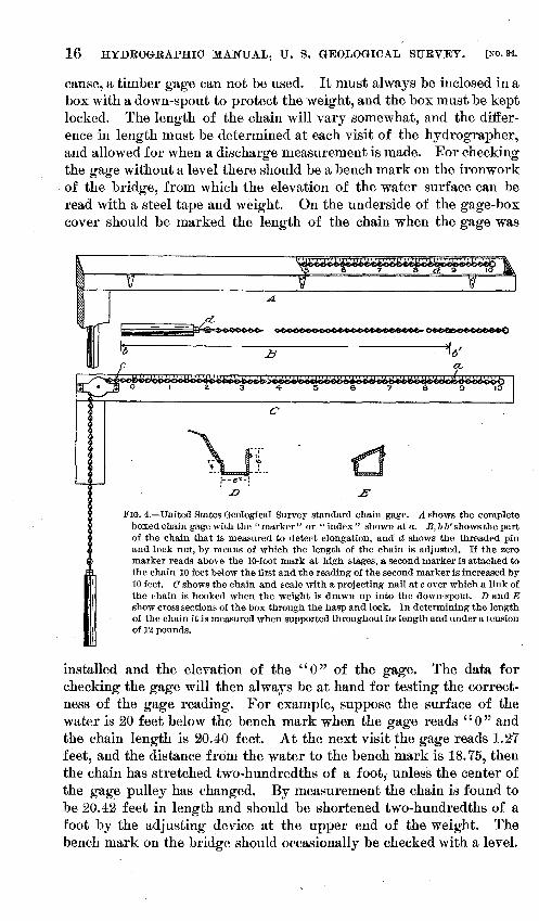
FIG. 4.-United States Geological Survey standard chain gage. A shows the complete boxed chain gage with the "marker" or "index" shown at a. B, b b' shows the part of the chain that is measured to detect elongation, and· d shows the threaded pin and lock nut, by means of which the length of the chain is adjusted. If the zero marker reads above the 10-foot mark at high stages, a second marker is attached to the chain 10 feet below the first and the reading of the second marker is increased by 10 feet. C shows the chain and scale with a projecting nail at cover which a link of the chain is hooked when the weight is drawn up into the down-spout. D and E show cross sections of the box through the hasp and lock. In determining the length of the chain it is measured when suppwted throughout its length and under a tension of 12 pounds.
installed and the elevation of the '' 0 " of the gage. The data for checking the gage will then always be at hand for testing the correctness of the gage reading. For example, suppose the surface of the water is 20 feet below the bench mark when the gage reads "0" and the chain length is 20.40 feet. At the next visit the gage reads 1.:&7 feet, and the distance from the water to the bench mark is 18. 75, then the chain has stretched two-hundredths of a foot, unless the center of the gage pulley has changed. By measurement the chain is found to be 20.42 feet in length and should be shortened two-hundredths of a foot by the adjusting device at the upper end of the weight. The bench mark on the bridge should occasionally be checked with a level.

M~~nHiio~~~iER.] GAGES, BENCH MARKS, AND STAY LINES. 17
All the hardware for the gage can be obtained at the Washington office, including the lock. It is necessary that the standard United States Geological Survey lock be used, so that the inspector can read the gage when he visits the station.
At stations where the importance of the work calls for a greater degree of accuracy than is given by reading the gage to half-tenths, a low-water gage can be used, marked to the quarters of tenths, and read to the nearest quarter of a .tenth, or marked to one-hundredths of a foot, and read to hundredths of a foot, the marking and reading to be determined by the district hydrographer.
A soale 2 or 3 feet in length and marked to hundredths of a foot can be used in some cases to ad vantage for measuring down to the water's surface from a well-defined point conveniently located.
BENCH MARKS.
There should be at least two bench marks at each gaging station; one preferably a copper plug set in a rock above high water, where it will not be disturbed, the other a point ori the ironwork of the bridge from which the elevation of the surface of the water can be read with a steel tape. In sand and alluvial river bottoms where rock can not be found the United States Geological Survey iron post can be used. A surveyor's bench mark is smnetimes found on a bridge, and it is therefore necessary to mark the bench Inark with "U. S. G. S." so that it can be distinguished from other marks of a similar kind. A cross cut on a ledge of rock or bridge abutment is sometimes used; a spike in a tree is only a tempora~y mark. Bench marks should be so placed that they can be easily found, and a full description forwarded to the Washington office, with the ''description of station."
STAY. LINES.
In a swift current the meter will be carried downstream in spite of any weight of lead . that can be operated by one man. To keep it directly underneath the point of measurement a stay line is used. This stay line may be a one-fourth-inch steel galvanized cable,. fastened to posts on the banks, carrying a small pulley. The meter is operated from this stay line, as shown in fig. 2 (page 13).
A pole projecting upstream from the bridge is sometimes used in place of a stay line for keeping the· meter at the proper depth. The meter is operated from this pole, as shown in fig. 3 (page 15). It is, however, difficult, even with these devices, to keep the meter at the desired depth, so that it is usually better to n1easure the velocity 1 foot below the surface and apply a coefficient to obtain the mean velocity. These devices can be used to advantage in obtaining characteristic vertical velocity curves from which this coefficient may be derived.
IRR 94-04-2

18 HYDROGRAPHIC MANUAL, U. S. GEOLOGICAL SURVEY. [No.94.
MEASUREMENTS OF DEPTH.
Facton .for compu,ting discharge.-The volume of water flowing in a stream in one second, or the discharge, is a product of two factorsmean velocity per second and cross section. The cross section is the product of two factors-mean depth and width. If the cross section were a rectangle and the velocity constant in all parts of it the measurement of discharge would be a simple matter, but the cross section of a natural stream is usually irregular in shape, and the velocity varies from the bank to the center and from the bottom to the surface. Considerable judgment is necessary, therefore, in selecting points in the cross section where depth and velocity should be measured, and in determining the method of measuring velocity that will secure a proper degree of accuracy.
It is found most convenient in current-meter work to divide the stream into parts 1, 2, 4, 5, 10, 20 feet in width, depending on the size of the stream and unevenness of the bed and to find the area, the mean velocity, and the discharge through each part separately. The total discharge is the sum of the discharges through the parts.
Fig. 1, (page 12) shows a meter station where measurements are made frmn a car suspended from a cable. The tags on the tag line directly over the cable mark the points where measurements of depth are made. The inclined gage is shown on the left side. The cross section is shown divided in parts by vertical lines directly over the tags. The dotted curved lines in the cross section are lines of equal velocity. The figure shows velocity being measured under one of the tags.
Sound/ngs. -Soundings should be taken at intervals across the stream, sufficiently ne:u· together to enable the cross section to be. computed to the required degree of accuracy. The distance between the soundings should depend upon the size of the streams, evenness of the bed, and the degree of accuracy required. For small streams, the interval may vary from 2 to 4 feet; for streams of moderate size, from 5 to 10 feet; and for larger streams from 10 to 20 feet, except around obstructions, where they should be taken about 5 feet apart.
A small, round weight is not so good for sounding as a large, flat one, because if the bed is soft or rough the former will settle into the bed or between the projections and give too great a depth.
When a very heavy weight is used for sounding in swift water it is well to have foot and half foot marks on the sounding line, so that the depth can be read when the lead restR on the bottom. Different colored bits of ribbon firmly tied to the sounding line and wrapped with insulating tape will generally answer the purpose. The part of the line that is immersed may preferably be of picture wire.
On account of the great difficulty of obtaining accurate soundings at high stages of water, depths for flood measureme~t should be com-

~~H!o~f~~im.J MEASUREMENTS OF DEPTH AND VELOCITY. 19
puted from soundings taken at a lower stage, either just before or just after the flood, provided the channel is of a permanent character.
The soundings can be taken with the meter on the line when the velocity in a vertical is being measured if the velocity is less than 3 feet per second. Care must be taken, however, to low~r the meter gradually and not allow it to suddenly strike the bottom.
In sounding in a swift current the lead should be directly underneath the point of observation and the line should not be bowed downstream. When the bed is very uneven two or more measurements of the depth at each point should be taken and the mean used. This can easily be done by holding in one hand the point on the line which touches some well-defined point on the bridge when the lead rests on the bottom, and comparing this point with the corresponding f>Oints on the line obtained by two or more trials. The distance measured on the line from the point obtained as the mean of these two or three trials to the point on the line when the lead is drawn up so as to just touch the surface of the water is the mean depth. When more .than 40 pounds of lead are used on the meter a cotton rope should be used for handling it, as the cable is not strong enough.
The initial point for soundings should be so marked that it can easily be recognized, and the points at which soundings are made should be clearly marked on the bridge or on the tag line of the cable or boat station.
MEASUREMENTS OF VELOCITY.
Gernm·al statement.-Velocity should be measured in each vertical where a sounding is taken except where the change is small, when it should be measured in alternate verticals. Several methods are in use for obtaining mean velocity in a vertical. They may be classified as single point, multiple point, and integration. In velocity observations the revolutions of the meter wheels should be counted for two equal periods so as to check the count. These periods are usually 50 seconds each.
Stngle-po,int 1net.hod.-Three single-point methods are in general use. In one, usually called the 0.6-depth method, the n1eter is held at the depth of the thread of mean velocity; in another, called the flood method, the meter is held 1 foot below the surface; in the third the meter is held at mid depth. In each of these methods it is necessary to apply a coefficient to reduce observed velocities to mean velocities. The advantage of the first one is that it is rapid and simple and the coefficient is unity. The advantage of the second is tbtt it is the only method that can be used during a flood. The third method is seldom used.
The mean-velocity method, ordinarily called the 0.6-depth method, will give very good results where the conditions are good-that is,

20 HYDROGRAPHIC MANUAL, U. S. GEOLOGICAL SURVEY. [No.94.
where there is a nearly straight channel with little obstruction, a bed regular in shape, and no sudden changes in velocity. The thread of mean velocity for such condition varies from 0.55 to 0.65 of the depth, its position depending on the depth, the ratio of width to depth, and the roughnes_s of the bed. For broad, shallow streams with gravelly beds, of depth from 1 to 3 feet, holding the center of the meter 0.57 depth below the surface will give satisfactory results. For ordinary streams, of depth from 1 to 6 feet, holding the center of the meter at 0.6 depth below the surface will give satisfactory results.
The flood method is to be used in making measurements at very high stages, when the single point and integration methods can not be used. The meter should be held 1 foot below the surface and a coefficient applied to the measured velocity to reduce it to mean velocity. The value of this coefficient varies from . 85 to . 90. An easily recognized mark on the meter line, one foot above the center of the meter, will be found useful in keeping the meter at the proper depth. (See also flood measurements, p. 23.)
.Integration rnethod.-ln the integration method the meter is kept in motion either from the surface to the bottom and back again to the surface in a vertical line, or diagonally from the surface to the bottom and back again to the surface, while it is at the same time moved across the channel. The latter, called the zigzag method, is seldom used, except in comparatively small artificial channels.
The vertical-integration method, consisting of moving the meter from the surface to the bed and back again. to the surface, counting the number of revolutions and noting the time, gives satisfactory results if the meter is moved slowly and at a uniform speed. It is a better method than the others where time is limited and where the conditions are poor (crooked channel, obstructions, etc.); also where the surface is retarded by drift, logs, or ice. It is a very good method for checking results obtained by the single-point method. This method is more difficult for one man than the point methods, and gives somewhat less information.
Multiple-po,int methods.-These consist of top and bottom; top, mid depth, and bottom; and vertical velocity curve. In the top-and-bottom method mean velocity is taken as the half sum of the top and bottom velocities. In the top, mid-depth, and bottom method the mean velocity is taken as one-fourth the sum of the top and bottom velocity and twice the mid-depth velocity. V =t(T+ B+2M). In the vertical-veiocitycurve method the mean velocity is computed from the velocities observed at several points in each vertical, as shown on pages 50-51.
The top-and-bottom n1ethod does not give satisfactory results where the bed is uneven. The results are, as a rule, too small. In a very shallow stream, 3 to 12 inches in depth, with sandy or fine gravel bed, satisfactory results are obtained by this method if the center of the lneter is held 0.15 of a foot below the surface and the same distance

U. 8. GEOLOGICAL SURVEY WATER-SUPPLY PAPER NO. 94 PL. II
A. CURRENT METER RATING STATION AT DENVER, COLO.
B . METHOD OF MAKING DISCHARGE MEASUREMENT BY WADING.

MURPHY, HOYT, J .AND HOLLISTER. MEASUREMENTS OF VELOCITY. 21
above the bed. If the bed is coarse gravel (particles 1 to 2-! inche,s in diameter) the center of the meter Rhould be held 0.15 of a foot below the surface and from 0.3 to 0.4 of a foot above the bed.
The vertical-velocity-curve method should be used when there is abundant time, for it gives more accurate results than either of the other methods~ bt1t it requires so much time that it is seldom employed except to check results obtained by one of the other methods. From three to eight observations are necessary in each vertical, each requiring from 50 to 100 seconds of time. A few vertical-velocity curves should be obtained at certain selected points in the. cross section if possible.
Low velocity limita,tions.-The current-meter and weir discharge comparisons made at the hydraulic la,boratory of Cornell University, described in Water Supply Paper No. 64, show that current-meter measurements of velocities less than about 0.4 or 0.5 foot per second are not reliable. The meter discharge is less than that shown by the weir, the error increasing as the velocity decreases and as the friction of the meter increases. For these reasons it is not advisable to attempt the measurement of the discharge at a place where the mean velocity is less than about half a foot per second. Inasmuch as there is always a small area of low velocity near the hanks and around piers, a rule was made by the hydrographer in charge, March, 1903, that hereafter when the velocity at a station becomes less than half a foot per second in more than 15 per cent of the cross section, the measurements there should be discontinued. At many stations where curr~nt-meter measurmnents can not be made when the flow becomes sluggish at low stages, a piace can be found within half a mile of the station where the veloeity can be measured by wading.
At each permanent gaging station where a high degree o:f accuracy is required a somewhat extended study should be made at different stages by the vertical-veloeity-curve method to test the reliability of the results obtained and to derive coefficients applicable to other stations having somewhat similar conditions.
Heas'ltring disclw1'ge by wad'l:11g (see Pl. II, B).-Discharge can often be measured more accurately than at the gaging station by wading in some chosen section where the conditions are good. Iron rods threeeighths inch in diameter and at least 3 feet long, with a long slot or thumbscrew in one end and the other end pointed will be found convenient for holding the ends of the tape during the measurements. Depth can be measured with a light rod, marked to feet and tenths, that can be made in a few minutes. The hydrographer should hold the meter as far to the side of him as possible and a little upstream so that there will be but slight obstruction offered by his body (see Pl. II, B). In a very small stream measurements should be made from a plank laid across it instead of by wading.

22 HYDROGRAPHIO MANUAL, U. S. GEOLOGIOAL SURVEY. [No.94.
CHECKS.
The field work of the discharge measurement should not be considered complete until it has been checked. The chain gage can be checked with a steel tape, as described on page 16. The observations of velocity can be checked rapidly by the integration method, and the computed discharge partially checked by plotting it on squared paper and comparing with station rating curve of the preceding year. If any discharge varies from the station rating curve by more than 5 per cent for ordinary stages at a station where the conditions are fair to good, or by more than 8 per cent where the conditions are fair to poor, the hydrographer should seek the cause in change in channel or in mistakes.
CLASSES OF DISCHARGE MEASUREMENTS •
.Mininuun-jlmo measure:ments.-Records of the minimum flow of a stream are in nearly all cases very important, and special effort should be made to secure them every season at each important station. It is not yery important to determine the smallest amount that flows past the station during the season, for this minimun1 may occur when the greater part of the natural flow is being held back by dams~ what is desired is the average flow for the month or week when the flow is least.
A larger number of discharge measurements are necessary to define the lower part of the station rating curve than any other part, because small changes in gage height have a much larger proportional effect on the discharge for the lower stages than the higher ones, and because the slope changes faster in the lower than in the higher parts of the curve.
When there are daily fluctuations in the discharge-as, for instance, where the water is held back by dams-care should be taken to have the gage read at such times that the reported "daily gage height" is the mean for the day; for example, if a gage is below a dam that holds back the water during the night, one reading should be taken when the water wheels are in use and one when they are shut down.
It is often advisable to have a low-water gage in addition to the one for other stages, one that can be read by the observer easily and with a greater degree of accuracy.
Facts in regard to the minimum flow of tributaries of each strea1n and their suitability for power and water-supply purposes should be collected by the hydrographer and reported to the Washington office,
,Jf
on form 9-213 or by brief reports. It is well to give also the dates and amounts of precipitation in inches at the nearest Weather Bureau station for some days preceding the date of measurement. Such facts can usually be obtained at small expense, and they add greatly to the value of the discharge records.
MURPHY, HOYT, J CI ... ASSES Ol!' DISCHARGE MEASURJ£MENTS. 23 AND HOLLISTER.
Flood:flow 1neasurements.~ The stage of a stream during flood usually changes so rapidly that a discharge measurement made at such a time, to be of greatest value, should be made in less than two hours; three or four observations of the velocity 1 foot below the water surface between each pier and one or two between each pile pier will usually answer this purpose. Depths can be obtained from previous soundings at a lower stage or from the cross section of the river at the station, developed after the flood.
Care must be taken to protect the current meter from injury by drift. When for any reason the meter can not be used, the surface velocity
can be obtained by means of floats. In wide streams where the conditions between piers are similar, if
the velocity is 5 or more feet per second and the bridge spans are 150 feet or more in length, it is not wise to attempt to measure velocity nearer to a pier than about 25 feet. When the measurement is taken the area of the pier should be neglected in computing the discharge. If the velocity is less than 5 feet per second the area of the pier (or piles in the case of trestle work) should be subtracted from the area in computing the discharge.
The gage height at which overflow of banks takes place should be noted, also any backwater effect. Facts in regard to character and extent of damage done by the flood should be obtained; also effect of obstructions upon the height of the flood.
Distr~:b1l,tion of discharge 1neasurements.-As far as possible diseharge measurements should be made at such river stages as wiH give a point on an undefined part of the station rating curve. Frequently there are several measurements made at about the same gage height and no measurement for 2 or 3 feet stage above or below them. By instructing observers to telegraph when the river reaches a desired stage the hydrographer can time his visit so as to obtain a point on the curve at which no measurements have been made.
Very often the hydrographer can obtain two or more points on the rating curve at a single visit. By remaining a couple of days at the station when the stage is high he can make four or more discharge. measurements cheaply, which may serve to fix a considerable part of the curve.
Miscellaneous discha1·ge 'lneas'WJ'ements.-A miscellaneous discharge measurement is one that is made at a distance from a permanent or temporary gaging station. The place of measurement should be referred to some easily found landmark-as, for example, "500 feet upstream from county bridge, 3 miles northwest of---," and the elevations of the water surface should be referred to some point that can be easily found and again used-as, for example, "10 feet below upper surface of floor beam, first span north end Southern Railway bridge, 3 miles south of " Facts in regard to the behavior of the

24 HYDROGRAPHlC MANUAL, u.·s. GEOl,OGIOAL SlTRVEY. [No.94.
stream, its minimum and maximum flow, and a comparison between the discharge at the time of measurement and low flow should be ascertained and reported.
When measurements are made at several places along a stream during a reconnaissance, allowance should be made for rain that has fallen in the interval between measurements between the places and on tributaries entel'ing the stream between points of measurement.
Winter dt8rJlwlrge measttre7nents.-The winter discharge of the important streams is desired at permanent gaging stations, where the conditions are such that reliable data can be obtained at reasonable cost. If ice does not interfere with the work, it should be continued during the winter, as at other seasons of the year.
If anchor ice forms at a station, a record should be kept showing the date of its formation, the height of backwater due to it, und whether much or little water is flowing at the time. Facts in rega1~d to the rise in the strean1 that lifts the ice but does not clear the channel should be noted.
At stations where solid ice forms, the observer should visit the station at least once a week to read the gage and note the condition of the stream. If the gage is a chain one, the ice should be cut away around the gage, the gage read, and the thickness of the ice measured, also the distance of the surface of the water above or below the surface of the ice. The observer should also note whether the ice is rough or smooth on the under side and the distance to open water above and below the station.
A rod with a crosspiece on the lower end, forming a T, is convenient for measuring the thickness of ice.
The vertical-integration method of measuring the velocity (by moving the meter slowly from the surface to the bed and back to the surface again, counting the revolutions, and noting the time) will be found satisfactory under ice. Some vertical velocity curves, however, should be taken at each measurement. A special station rating curve must be used for periods when ice interferes with the natural flow.
GAGE READINGS.
Computations of discharge and run-off are usually based on gage readings taken one or more times daily. If any of these are in error, the results obtained from them are in error also. Every effort should therefore be made by the hydrographer to secure thoroughly reliable gage readers. No pains should be spared to teach them to read the gage correctly and to properly record and report the readings. They should realize the importance of the records they are taking, and should know that means are being taken to see that the records are reasonably correct.

MURPHY, HOYT, J GAGE READINGS AND CROSS SECTIONS. AND HOLLISTER. 25
At each visit to the station the hydrographer should examine the g·age reader's book and make comments thereon. The reading of the observer and hydrographer on the day of visit should be compared.
A gage reader is more likely to read with regularity and accuracy a gage that can easily be reached and seen than one which requires unusual effort or risk to read; hence, except in rare cases, a chain gage should not be placed on a high rail way trestle bridge, nor on a structure where it is necessary for the observer to climb, nor where he is obliged to kneel down and reach out over some part of the structure.
Rod gages frequently becon1e waterworn and covered with dirt, so that they are difficult to read. Occasionally the bed fills in around the lower end of the gage, so that it is necessary to keep open a channel of running water to the gage. These points and many others the hydrographer must keep in mind and provide for in order to secure satisfactory records of daily gage heights.
STANDARD CROSS SECTION.
There should be prepared for each permanent gaging station a cross section of the stream showing the contour of the channel to points on each bank above the highest flood water, the piers, and other obstructions, and showing elevations referred to the zero of the gage. An engineer's level or plane table will be necessary fer this purpose. From such a cross section approximate depths can be found for any gage height; also changes in channel due to scour or fill. It also assists very materially in the preparation of the station rating table.
DATA ON FLOODS.
Hereafter there will be prepared at the end of each year a watersupply paper on the destructive floods of the year, showing their magnitude and extent, the destruction wrought by them, and the engineering features involved in the prevention of their destruetive action. When a notable flood occurs in the area in charge of any district hydrographer he should make a special effort to visit the locality during the flood, or very soon thereafter, ancl obtain all facts possible concerning the height, quantity of water, destruction wrought, and reasons therefor, and prepare a report thereon, adding comments concerning the action of bridges, buildings, levees, etc., along the stream .. In such investigations care should be taken to verify data not obtained from actual observation, especially any data necessary for computing discharges. If discharge is computed from data obtained principally from flood marks, special care must be taken, because these marks are often misleading.
26 HYDROGRAPHIC MANUAL, U. S. GEOLOGICAL SURVEY. [No. 94.
RECONNAISSANCE.
A reconnaissance of a stream is made for the purpose of locating a gaging station, investigating water power or water Atorage possibilities, or studying the destruction wrought by floods or the pollution of the water. •
All data that have any bearing on the question studied should be collected, and sketches should be freely used, showing the relative positions of objects described. The notes should be very full and clear, so that they will convey correct ideas of facts after they have been in part or wholly forgotten.
A reconnaissance for the selection of a gaging station or for investigating power and storage possibilities is usually made when the stream is low, as data collected for these purposes are more valuable at this stage t4an at the high stages.
The instruments used are a hand level, compass, ~teel tape, and current meter.
The topographic features of the watershed, such as the elevation, slopes of surface, width of valleys, character of rock and soil and vegetation, should be noted; the slope of the stream, location of the used and unused power, location and magnitude of principal tributaries, high-water marks, the extent to which the water is used for industrial purposes, kind of industries, and the kind· and sources of pollution should also be noted.
The discharge of a stream and its principal tributaries should be measured, and a temporary bench mark should be left at each point of measurement, so that if a subsequent measurement is made at that point it can be compared with the former.
DESCRIPTION AND CARE OF INSTRUMENTS.
GENERAL STATEMENT.
Hydrographers are responsible for the care of current meters and other Government instruments intrusted to them, and are required to account at stated time~ for all such property in their keeping. Since the accuracy of stream gagings depends largely upon the eorrect working of the current meter, great care should be exercised in handling these instruments and in keeping them properly adjusted. Inaccurate work and poor results can often be traced directly to neglect in caring for instruments.
CURRENT METER.
The following description and suggestions regarding the use and care of the small Price electric current meter (see Pl. III) are intended for the guidance of hy~rographers in the field:
When in use the meter is suspended by a double conductor cable of No. 14 or No. 16 flexible copper wire, heavily insulated. Wire of that

U. 0 . GEOL081CAL SURVEY WATER-SU PPLY PAPER NO. 94 PL. 111
PRIC E ELECTRIC CURRENT METERS, WITH BUZZERS.

MURPHY, HOYT, J AND HOLLISTER. CURRENT METER. 27
size is of sufficient strength to hold the meter and weights, and it obviates the necessity of additional rope for suspending the equipment when the weight used is less than 40 pounds. The cable is attached to the meter with a spring snap hooked into the circular end of the trunnion P, fig. 5. The heavy copper wires are connected with the meter binding posts h and d by smaller and more flexible wires. The wires connected with the binding post d should be threaded through the metal loops on the yoke o, within the trunnion frame, and at g. It is desirable that these wires should be flexible and loose, to allow the meter to swing free in the vertical plane when it is in use.
Lead weights (a, fig. 6), provided for the purpose of holding the meter steady in moving water (the higher the velocity of the stream
Section A-A
~r;: ~-··-~.
f
~ 1 e
FIG. 5.-Cross section of small Price electric current meter, showing details.
the greater the weight), are attached to the lower end of the trunnion by means of a detachable weight stem (b, fig. 6).
The weight vane (c, fig. 6) should be attached to the weights at all times when the meter is used suspended from a cable. When gaging small or shallow streams it may be necessary to make observations by wading. Under such circumstances it will be more convenient to dispense with the lead weights and attach the meter to a light rod or pole. If desired a brass standard can be supplied for attaching the meter to the rod.
The meter is supported in a trunnion or hanger (P, fig. 5), and is free to swing in a vertical plane. One revolution of the wheel or cups is
28.. HYDROGRAPHIC MANU <\.L, U. S. GEOLOGICAL SURVEY. [No. 94.
indicated by a buzz of the electric buzzer, the observer being required to count the number for a certain interval of time, preferably fifty seconds, as the computations can more easily be made from that number. A second observation of the same length of time should immediately follow the first observation in order to verify the count.
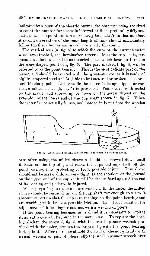
The vertical axis (n, :fig. 5) to which the cups of the current-mete.r wheel are attached, and hereinafter referred to as the cup shaft, terminates at the lower end in an inverted cone, which bears or turns on the cone-shaped point of e, :fig. 5. The part marked l, fig. 5, will be referred to as the point bearing. This is the most delicate part of the meter, and should be treated with the greatest care, as it is made of highly tempered steel and is Fable to be fractured or broken. To protect this sharp point bearing while the meter is being shipped or carried, a milled sleeve (k, :fig. 5) is provided. This sleeve is threaded on the inside, and screws up or down on the screw thread on the extension of the lower end of the cup shaft shown in fig. 5. When the meter is not actually in use, and before it is put into the wooden
FIG. 6.-Weights and weight vane of small Price electric current meter.
case after using-, the milled sleeve k should be screwed down until ·it bears on the top of q and raises the cups and cup shaft off the point bearing, thus protecting it from possible injury. Thir;; sleeve should not be screwed down very tight, aR the shoulder of the journal on the upper end of the cup shaft will be thrust hard against the end of its hearing and perhaps be injured.
When preparing to make a measurement with the meter the milled sleeve should be screwed up on the cup shaft far enough to make it absolutely certain that the cups are turning on the point bearing and are working with the least possible friction. This sleeve is n1illed for adjustment with the fingers and not with a wrench or pliers.
If the point bearing becomes injured and it is necessnry to replace it, an extra <me will be found in the meter case. To replace the bearing slacken the screw i, fig. 5, with the small spanner wrench provided with the meter, remove the large nut q with the point hearing locked in it. After its removal hold the head of the nut q :firmly with a small wrench or pair of pliers, slip the small spanner wrench over

MURPHY, HOYT, J AND HOLLISTER. CURRENT METER. 29
the flat sides of the nut f, and loosen it. Remove the nut f with the :fingers, and with a small screw-driver take out the damaged bearing from the large nut q. Replace the large nut q, and with the spanner wreneh screw it :firmly into yoke o. Remove the loek nut from the point bearing to be inserted, and with a screw-driver send the latter through the large nut q. Great care should be exercised in making this most important adjustment of the current meter. A slight amoun_t of play or movement of the cups up and down must be allowed, so that they will revolve freely and without friction. When the point is almost up turn it, a part of a revolution at a time, with the screwdriver, until the proper adjustment is obtained. After the adjustment has been made a full turn of the point bearing in the nut q would crush the sharp point of the bearing e into the inverted cone of the cup shaft and break the point. After the point has been satisfactorily adjusted remove the nut q, with the point in it, put the Joel~ nut on the point, and draw it down on the face of the large nut and thus preserve the adjustment. Should the adjushnent of the meter be too tight the results obtained from its use will be erroneous. An examination of the meter when received from the Survey will give an idea of the proper adjustment. Do not disturb the adjustment of the meter unless it is neeessary to put in a new point bearing.
Section A-A, :fig. 5, shows the eonstruction of the binding post and eontact spring of the meter. A flexible, well-insulated copper wire (No. 20, or smaller), is drawn through the metal loop g of the yoke o, and the end of the wire free from insulation is thrust into the metal binding post d and secured by the small set screw. This 1netal binding post terminates in a slender platinum spring (a), which extends through the bard rubber nipple c into the contact chamber to 'ln. The top or upper end of the cup shaft terminates in the contaet chamber with an oval-shaped eccentric (1i~), which makes a contact with the spring a at each revolution of the meter cups. This contact can be prolonged or shortened by bending the point of the contact spring in the contact chamber in the desired direction. The oval-shaped eccentric end of the cup shaft is detachable, and can be removed by taking off the eap R, holding the cups :firmly, and applying a screw-drivel~ to the small slotted head.
The insulating nipple c is made of hard rubber, and is likely to break if the binding post d receives a sharp blow. An extra insulating nippple will be found in the small tin case in the meter box. Before removing or replacing the binding post d, take out the eccentricshaped top of the cup shaft m. If this is neglected the contact spring will be destroyed by the turning of the binding post.
In using and handling the meter care should be taken that it does not fall or get a hard knock which may injure the cups or cup shaft.
30 HYDROGRAPHIC MANUAL, U. S. GEOLOGICAL SURVEY. [No. 94.
An injury to either will change the rating of the meter, and if this occurs it should be immediately returned to headquarters for repairs. When using the meter in streams containing grass or mo~;s, examine the instrument frequently to see that nothing has lodged on or wrapped around the cup shaft n.
If the meter has not been used for some time before a measurement is made it should be carefully cleaned and oiled.
BATTERY AND BUZZER.
In charging the battery cell used with the electric buzzer furnished with the current meter, one-half teaspoonful of bisulphate of mercury is sufficient. Fill the cell with water and insert the zinc pole with the rubber stopper attached. When putting the battery cell in the leather case be sure that the small platinum point on the lower end of the cell and the screw head of the rubber stopper make perfect contact with the copper plates. If the buzzer makes but a faint clicking sound instead of a buzz, remove the metal cap covering the buzzer, and with a knife blade adjust the small upright brass point by bending until the armature produces the desired sound. Never allow the liquid to remain in the battery cell over night, as it will generate gas and produce pressure sufficient to cause the cell to leak at the rubber stopper, and the solution escaping will destroy the leather of the brass parts of the buzzer. When measurements are needed requiring a long time for completion the stopper should be removed occasionally to relieve the pressure due to the gas.
When preparing to make a discharge measurement charge the battery cell of the buzzer, remove the meter from the case, take out the weights, weigh stem and vane, combine them as in fig. 6, and attach them to the meter with the spring pin provided; turn up the milled sleeve k; be sure that the meter is well oiled, and turn the cups to see that they revolve freely and that the buzzer responds to each revolution.
After making a discharge measurement, or at the close of a day's work with the meter, unscrew the large nut q, with the point bearing in it, and examine the point carefully to detect injury. With a piece of soft cloth remove the water in the opening at the lower end of the cup shaft, oil generously, and replace the bearing. Then remove the screw cap R, turn the meter over to allow the water to run out of the contact chamber, put in a plentiful supply of oil, and replace the cap; this protects the top of journal bearing of the cup shaft from rusting. After this has been done turn down the milled sleeve k, to protect the point bearing while carrying the meter, remove the battery cell, empty out the liquid, wash the cell with water, and pack the meter carefully in the case, when it will be ready for future use.

MURPHY, HOYT, J AND HOLLISTER. CURRENT METER.
RERATING OF METERS.
31
Whenever a meter point is found to be broken or injured it should be replaced by the other point bearing which accompanies the meter. If the cups are injured or the cup shaft is bent the meter should at once be sent to headquarters for repairs. Every meter that has been used to any considerable extent after rating should be rerated before the beginning of the next field season. .
For description of meter-rating stations and method of rating meters see Water-Supply and Irrigation Paper No. 56, page 34.
The rating table of a small Price meter when held with a rod differs son1ewhat from that applicable to a similar meter wh~n held with a cable and free to tip, so that if this meter is used with a rod care must be taken to employ the proper rating table.
RECORDS AND REPORTS.
General statement.-The regulations which govern all work done by the United States Geological Survey require that all original records of data collected shall be filed for public reference at the office of the Survey, in Washington. These records should be so clear and full in all respects that they will be intelligible at any time to engineers and other persons who ma,y desire to consult them.
D1tties of distr£ct hydrographers and engineers.-In order to systematize stream measurements the country has been divided into districts, each of which has been placed under the supervision of a district hydrographer or engineer. It is the duty of this officer to superintend all stream measurements in his territory, and he is held responsible to the chief engineer for the character of the work done by the men under him. He should have immediate supervision of all the more important features of the work which can not be intrusted to his assistants. The stream-gaging work, which is carried on in connection with the investigation of irrigation projects, should be under the direct charge of a man designated by the district engineer, through whom he shall report. This man should be held responsible for the proper execution of all stream-measurement work, and all data concerning such work must be transmitted through him.
Care in keeping 1'ecords.-As the work of the Government is for the general public, it is subject to more severe criticism than the work of private engineers. It is therefore essential that great care be taken in the work and that every possible excuse for criticism be eliminated. All necessary notes should be taken in the field, and, as a special precaution, at the end of each day's work notebooks should be reviewed and amplified while the facts and conditions are still fresh in the mind of the hydrographer or engineer. Careful cross references should be

32 HYDROGRAPHIC MANUAL, U. S. GEOLOGICAL SURVEY. [No. 94.
made, and sketches to show the relative location and details of special features should be freely used.
Oomputing.fieldnotes.-Original computation of all field notes should be made, when possible, in the field, or the notes should be computed at as early a date as possible, and in no case should the hydrographer allow large quantities of undigested data to accumulate.
Olwcking of records.-All records and notebooks should be examined and checked before they are transmitted to the Washington office. In order to fix the responsibility for errors each book or sheet should be stamped and initialed "-Computed by---," ''Computations checked by---," or '"Examined by---." All records are carefuJly examined at the \Vashington office, and if incomplete they will be returned to the district engineer or hydrographer for correction and amplification.
DupUcate r·ecords.-The district hydrographer may cause to be prepared such duplicate copies of original notes as may be necessary for reference in his office. Too much duplication should be avoided. The original records nmy be loaned at any time from the files of the 'V ashington office.
Transrrdssion of data to lYasltington office.-All data, correspondence,and other material from each hydrographic district should be transmitted through the district hydrographer or engineer to the Washington offic~. This material should be initialed by the district hydrographer or by some one designated by him. With the exception of single gage-height and discharge-measurement cards, mailed as postal cards, all data sent should be accompanied by a letter stating the amount and character of material furnished. No data will be accepted by the "T ashington office which is not 0. K. 'd by the district hydrographer or by some one designated by him.
Standa,rd for·ms.-As far as possible the standard forms furnished by the Survey should he used in transmitting data. Such information as can not be written on these forms and cards may he transmitted on the separate sheets of paper furnished by the Survey. These sheets should be of the standard letter size, 8 by 10 inches, as this is the size for which the file boxes of the Washington office are designed. Pieces of paper of o~d sizes should not be used either for drawings or reports. Sketches and maps accompanying reportR should, whenever possible, either be on paper of standard size, or should be folded to conform with this size in order that they may be filed with the written reports.
The following is a list of the forms which have been adopted for general use in hydrographic work. These are intended both to minimize and simplify the work. Whenever forms become too numerous they lose their usefulness. Every effort has, therefore, been ~ade to

MURPHY, HOYT, ] AND HOLLISTER. RECORDS AND REPORTS. 33
reduce the number of forms to a minimum and to. prepare these in the simplest manner possible.
List of standa.rd .forrns.
GAGE-HEIGHT FORMS.
Form 9-176.-Gage-height cards, for transmitting observer's daily gage readings to the resident and district hydrographer, to be forwarded to the Washington office.
Form 9-175.-0bserver's gage-height books, for recording daily gage-heights at river stations.
Form 9-212.-Daily gage-height form, for tabulating daily gage-heights, arranged by months, with sufficient space for one year's records.
DISCHARGE-MEASUREMENT FORMS.
Form 9-198.-Current-meter notebooks for recording notes of discharge measurements, vertical-velocity curves, and other meter work.
Form 9-221.-Card for reporting discharge measurements to the Washington office. Form 9-207.-For tabulating discharge measurements for regular stations, with
spaces for all necessary data. Form 9-223.-For tabulating miscellaneous discharge measurements. Form 9-244.-For describing the method of and for reporting miscellaneous dis
charge measurements made by floats, to be used in regular work.
COMPUTATION FORMS.
Fm·m 9-192.-For tabulating daily gage heights and their correspondingdi~charges, with spaces for totals, monthly means, and run-offs. The form provides for one year's records, arranged by months.
Form 9-210.-For tabulating station rating tables. Form 9-206.-For tabulating meter rating tables.
REPORT FORMS.
Form 9-197.-Description of river stations; to be used for describing both temporary and permanent stations.
Form 9-237.-For reporting the conditions at river stations and giving the cost of maintenance.
Form 9-213.-For reporting changes and other information in regard to river stations.
Form 9-171.-Monthly report on river stations. Form 9-245.-Monthly report of services, giving daily employment.
VOUCHERS AND MISCELLANEOUS FORMS.
Form 9-230.-A blank form ruled for miscellaneous tabulation. Form 9-904.-Cross section notebook. Form 9-903.-Levelnotebook. Form 9-253.-Index blanks for notebooks. Form 9-019a.-Subvouchers. Form 9-009.-Service vouchers for field men. Form 9-D05.-Fie1d vouchers. Form 9-D15.-Traveling expense vouchers. Form 9-918.-Expense account notebook.
Aside from these forms, which are in general use, there are several forms which are used in the Washington office. and in special work,
:J~~ 94-04--3
34 HYDROGRAPHIC MANUAL, U. 8. GEOLOGICAL SURVEY. [No. 94.
Hydrographers desiring forms for any purpose will kindly forward a description of what they want~ and they will, as far as possible, be supplied.- ·
INSTRUCTIONS FOR USE OF FORMS.
Observers' qage-height books (form 9-175).-In the observers' gageheight books are recorded the daily stage of rivers, together with miscellaneous iQformation, such as data in regard to :floods, ice, weather conditions, etc. The observer should be instructed and trained to keep the books in as legible condition _as possible, and to insure this the hydrographer should inspect the gage-height book at each visit to the station. At the end of each year the observer should be furnished with a new book and the old one should be returned to the district hydrographer's office, where it should be examined, checked, and forwarded to the Washington office for :filing.
Gage-height cards (form 9-176).-Gage-height cards should be made out at the end of each week by the local observer and mailed to the district hydrographer's office, where they should be carefully examined. In this examination all missing data, such as the date, name of station, river, State, etc., should be supplied. The gage heights should be compared with the gage heights for previous weeks to see that no unaccountable changes due to error in reading the gage 'have been reported, and the column for means should be :filled in. A copy of the data on the cards should be made for the office of the district hydrographer and the originals should then be forwarded to the Washington office.
Ourrent-1netm· notebooks (form 9-198).-In these books are recorded the :field notes of discharge measurements and V€rtical velocity curves. In all cases the original data should be written in the book at the time of the measurement. In no case should it be copied from rough notes in other books. Explanatory notes, cross references, and sketches should be added at the end of each day's work. The blank spaces at the head of each page are to be filled in; also the columns for the original data. In the column headed "Depth of observation" the exact depth for each observation should be recorded; "at 0.6 depth" is not sufficient; the position of the initial point, edges of water, edges of dead water, and number of channels should be stated; also the direction and force of the wind, roughness of the bed, and any other factors on which the accuracy of the work depends. A statement of the reliability of the results should be made in the notes. If the measurement is not made at the station the approximate distance and a brief statement of the conditions at the places of measurement should be made. The velocity at the water's edge and at the edge of piers, shoals, etc., should be estimated and :recorded. The

MURPHY, HOYT, J AND HOLLISTER. RECORDS AND REPORTS. 35
cross-section pages at the end of the book are to be used for sketches and additional explanatory notes. Cross-reference notes should be -made referring to these pages. Page 48 shows a sample page of current-meter notes with the computations for the same.
Discharqe measurement card._~ (for1n 9-~~1).-These are to be made out by the hydrographer and sent to the local office when the measurements are computed. Care should be taken to fill out all portions of the card. Special attention is called to the remarks and the portion for "gage verified and found" (seep. 16 for explanation). Measurement is not complete without this data. Either "At permanent station," ''Temporary station," or ''Miscellaneous measurements" should be crossed out, so that the card shows at once to which class of measurements it belongs. All cards should be carefully examined before they are sent to the Washington office.
Forn~ 9-~13.-In order that the office may keep a complete and systematic record of all the changes and additions at river stations, such as new gages, bench marks, changes in the river bed, equipment, etc., form 9-213 has been prepared. This form is to be used in sending in to the office any data- in regard to the regular river stations which affect the measurements or the station in any way. These forms are filed with the regular data for the station, and are necessary in order that the Washington office may thoroughly understand the conditions under which the station has been maintained and the measurements made.
Description of river stations (form 9-197).-Special care should be taken in filling out the description of stations. The description should be so clear that_with it a stranger could go to the locality and be able to continue the work at the station. The name of the station should be carefully chosen, and it should definitely locate the station with respect to some of the prominent features in the vicinity, as above or below some creek or tributary, at a certain bridge, near a certain township line, etc. If there has ever been another station on the same stream in the vicinity of the new station, the relative location of these two stations should be stated, and, if possible, the relation of the zeros of the two gages. In order to facilitate the preparation of rating curves it is desirable that care be taken in preparing a sketch of the cross section of the stream. This, with the other sketches, may be made on cross-section paper and attached to the description. It is also desirable to cut from a topographic sheet or some other map a section which will show the location of the station.
Indewinq notebooks.-All notebooks should be carefully indexed on the regulation blank 9-253 before they are forwarded to the Washington office. The index slip should be left loose in the book, in order
36 HYDROGRAPHIC MANUAL, U. S. GEOLOGICAL SURVEY. [No. 94.
that the file clerk may more readily check the contents. It will then be pasted on the cover. The following shows a sample of the indexing:
9-253 DEPARTMENT OF THE INTERIOR.
UNITED STATES GEOLOGICAL SURVEY.
HYDROGRAPHIC RECORDS.
Kind of notes, Current-Meter. File No., 5399. Date received, Ji'ebruary 1, 1904. Hydrographers, Chandler, E. F., ai~d Richards, R.
Stream. Locality.
Heart ------------------ Church's ardton).
ranch (Rich-
Little Mt~ssouri ___________ Jfedora ----------------Jfouse __________________ Minot _________________
Pembina ________________ Neche ______ ....... _ . __
Red Lake _ .• __ . _ ..... _ .. Crookston. ___ ••. __ . ___ •
" " E. Grand Forks _ .•.•... .................................
Red River of the North_. __ Grand Forks . •....••.••
" " " " " " (above forks)
State.
N. Dak __
" "
Minn ----
N.Dak ••
"
Date.
1903.
s. 5-------
" s. 25, 0.5 ••
s. 28------
0. 12--.--.
Ag. 4------
A g. 1,4 ....
A g. 1,4 ....
Page.
8
7
9,11-12
10
13-14
6
1-2,4
3,5
NOTE.-Rivers to be arranged in alphabetical order. The same entries occurring several times should be entered but once and the various pages given.
If references are to consecutive pages use dash, e. g., 9-12; if not to consecutive pages, use comma, e. g., 1, 3, 5, 8.
Enter under the noun, except where the adjective is a recognized part of the name, thus, Platte, South fork; but North Platte, Little Missouri.
Iands of reports.-Reports in general may be divided into two classes: First, the regular monthly reports of work accomplished; second, special reports transmitting data or information to the office. The regular monthly reports are intended to give the hydrographer an idea of the work that is being done and the progress that is being made. The reports containing data go into the office files as permanent records and are used in making up the. publications. An effort should be made to maintain this division.
Use of maps and sketches.---In all reports, descriptions of stations, etc.,.maps and sketches should be freely us~d to show the location of river stations, the sections of the country visited, and other details. In case topographic sheets have been prepared for the region unaer investigation the hydrographer should supply himself with copies of these sheets and make use of sueh portions of them as cover the territory examined. Upon these maps special features should be shown. In the absence of topographic sheets land office and other maps should be used.
Repm·t 'maps.-Each district hydrographer should prepare a map of his territory from the best maps available. This map should show,
MURPHY, HOYT, J AND HOLLISTER, RECORDS AND REPORTS. 37
with their names, the principal stream::; and other features on which work will be carried on. He should divide his territory into its principal drainage areas and indicate them on the map. When this division has been decided upon, it should be carefully adhered to, so that the measurements and other work can be referred to drainage areas. These maps may be prepared on tracing cloth, and from them theW ashington office can make a paper negative, from which as many copies as desired can be supplied. This map is desired for use in reports. With each report a map should be transmitted showing the localities that have been investigated, which should be referred to by number, so that the chief engineer can at a glance see what is being done .
.Monthly reports.-A monthly report of the district hydrographer is to be made up of-
(a) A brief written report stating what was done during the month and the condition of the work.
(b) Form 9-171, on which ghall be given an alphabetical list of the river stations in each State in his district. Stations in different States should not be shown on the same sheet, as these sheets are :filed by States, so that separate sheets should be prepared for separate States. In the column of remarks, such notes as ''New bench mark established," "Station discontinued" (with date), "Station established" (with date), "Temporarily closed," etc., are to be given. Names of the stations which are temporarily closed should be kept on the list until they are discontinued.
(c) Form 9-245 is designed for use by each man under the district hydrographer. On this form should be briefly stated what the employee did on each day during the month. Such general statements as clerical work, :field work, etc., are not sufficient. In preparing the monthly report it is suggested that the district hydrographer should have each man under him :fill out form 9-245 and form 9-171 for the stations which he has visited. From these two forms the general monthly report can be taken.
Each :field assistant and a distant hydrographer, when on :field trips, should report to the district office immediately after visiting a station or after completing a reconnaissance or any piece of work, the general results of the work done, and such detailed information as is necessary in making up the monthly report for that district. This enables the district hydrographer to complete his report without 'waiting for the return of an assistant who is making an extended trip.
Resident hydrographer's monthly report.-The following is a sample form for monthly report of resident hydrographer:
ATLANTA, GA., October 31, 1903. Mr. F. H. NEWELL, Chief Engineer.
DEAR Sm: The following is a report of hydrographic work carried on in the States of Alabama, Georgia, and Tennessee during the month of October, 1903:
The following men were engaged: Messrs. M. R. Hall, J. M. Giles, and 0. P.

38 HYDROGRAPHIC MANUAL, U. 8. GEOLOGICAL SURVEY. (NO. 94
Hall of the regular force, and Messrs. W. G. Green and B. S. Drane of the temporar: force. Their duties were as follows:
M. R. Hall had general supervision of the work, spent ten days in the office il general correspondence, preparation of descriptions, computation on meter noteE and miscellaneous duties. The remainder of the month was spent in making : reconnaissance of Flint River and its tributaries.
J. M. Giles spent the whole month in the :field, making meter measurements repairing gages, and establishing bench marks.
0. P. Hall spent the whole month in the office, plotting discharge measurement and making rating tables.
TV. G. Green was employed for ten days during the month in making low-wate measurements.
B.S. Drane was employed for twenty days during the month, ten of which wer1 spent in the field assisting in the reconnaissance of Flint River; the remainder of th1 time was spent in the office working on the report of the work.
The accompanying lists show the distribution of the gaging stations in the variou States; also the work done at each station. On the index map is indicated th1 lo_cation of the stations and of the localities investigated.
The accompanying reports and forms give a portion of the data mentioned in thiJ report. The remaining data will follow in a few days.
Very respectfully, M. R. HALL, Hydrographer.
9-171. DEPARTMENT OF THE INTERIOR.
UNITED STATES GEOLOGICAL SURVEY.
DIVISION OF HYDROGRAPHY.
Atlanta, Ga., October 31, 1903. Mr. F. H. Newell,
In chargE- of Divison of Hydrography.
SIR: The following is a brief statement of the hydrographiq work preformed during the month o: November, 1903, under the direction of M. R. HaU;
RIVER STATIONS MAINTAINED, ESTABLISUED, OR DISCONTINUED.
1 No.ofdis-Stream. Station. State. charge Remarks. measure-
ments.
Alabama River • __ ••. Montgomery .... Alabama •.. 0 New B. M. established Nov. 15, 1903.
Alabama River . _ . _ .. Selma ______ •••. " 1
Black ·warrior R _____ Cordova .••••• _. " 0
Black Warrior R .• ___ Tuscaloosa .•••. " 0 Discontinued Nov. 30, 1903.
Cahaba River ___ . ____ Centerville • ___ •. " 2
Choccolocco Cr _______ Jenifer __ - •.•• - . " 1
Coosa River •• _ ••• ___ Riverside •• --_.-,,
1 Gage washed out, Nov. 10; replaced Nm·. 20 •
. Under" Remarks" state date of establishment or discontinuance, changes in gage, interruptions in observations, etc. A brief report covermg any matters of interest occurring during the month, and form 9-245, should usually accompany this form. These make up the monthly reports of the resident hydrographers.

MURPHY, HOYT, J AND HOLLISTER.
9-245.
RECORDS AND REPORTS.
DEPARTMENT OF THE INTERIOR.
U N I T E D S T AT E S G E 0 L 0 G I C A L S U R V E Y.
HYDROGRAPHIC BRANCH.
Report of services rendered by J. M. Giles during month of November, 1903.
39
[To accompany vouchers form 9-009 or subvouchers 9-019, giving briefly the character of work performed each day.]
1. Sunday.
2. Plotting discharge measurements, checking gage-height cards.
3. General correspondence and report on reconnaissance of Flint River.
4. Measured discharge of Alabama River at Salem, en route to Montgomery.
5. Measured discharge of Alabama River at Montgomery.
6. Computing discharge measurements and general correspondence.
7. Making up monthly reports.
I certify that the services were rendered as above stated.
Approved by M. R. Hall. J. M. Giles.
Reports on reconnaissance, surveys, investigations, etc.-As soon as practicable after the completion of the reconnaissance work, surveys, investigations, etc.,· a comprehensive report should be transmitted, stating concisely the information collected and the deductions which have been made, based upon the investigations. It is not desirable to accumulate data for a semiannual or yearly report. The material should be separated, as far as possible, into independent unit reports, and these should be transmitted as the work progresses.
Reporting new river stations.-When a river station is established a· statement should be transmitted, together with a description of the station, on form 9-197, stating the general reasons for establishing the station and the conditions which led to its establishment at the particular site selected.
Authority for carrying on work.-At the beginning of each season or before starting work which involves a considerable expenditure of money, the hydrographer or engineer in charge should submit for the approval of the chief engineer a brief outline of the work which it is proposed to carry on. This should state the purpose for which the data are to be collected, the cost, and other details which will give the chief engineer an idea of what it is proposed to do. Approval of the plan is to be considered authority for carrying on such investigations as may be deemed necessary to accomplish the end desired.
Furnishing information to the _public.-All data collected by Survey employees should be submitted to the Director through the hydrographer-in-charge before it is given to the public. In general, requests for data which are ready for distribution should be addressed to the

40 HYDROGRAPHIC MANUAL, U. S. GEOLOGICAL SURVEY. [No.94.
Director or the hydrographer-in-charge at Washington. When, however, requests are received by the district hydrographers or engineers they may furnish the information direct, if in so doing they are satisfied that the Survey will be in no way involved. Copies of all such requests and their answers should be sent to the hydrographer-incharge for the Washington letter files. When the district hydrographer receives requests for data and he has some doubt concerning the advisability of complying with the request, he should prepare a letter containing the information desired, for the signature of the hydrographer-in-charge, who will decide whether the information should be given out. . A carbon copy of the reply, with the answer and original request, should accompany the original request, so that a record of the data furnished may be kept in the washington office.
Miscellanemts inj'orm.ation.-It is expected that each district hydrographer and his assistants shall be on the lookout for any valuable information on the hydrography of the section in which they happen to be. This information should be systematically collected and carefully filed and indexed so as to be easily consulted. It is suggested that each employee supply himself with a small pocket case to hold 3 by 5 inch index cards. When in the field, items of importance may be noted on these cards, one subject to a card, and these, when filed in the office, will be a valuable source of information.
Publications contain·ing progress 'reports of stream measurements.The progress report of stream measurements for each year contains the re~mlts of the year~s field work, including all original data, such as gage heights and discharge measurements, together with the office computations.
The following is a list of these publications by years:
1888. Tenth Annual Report, Part i. 1889. Eleventh Annual Report, Part II. 1890. Twelfth Annual Report, Part II. 1891. Thirteenth Annual Report, Part III. 1892. Fourteenth Annual Report, Part II. 1893. Bulletin No. 131. 1894. Sixteenth Annual Report, Part II. Bulletin No. 131. 1895. Seventeenth Annual Report, Part II. Bulletin No. 140. 1896. Eighteenth Annual Report, Part IV. Water-Supply Paper No. 11. 1897. Nineteenth Annual Report, Part IV. Water-Supply Papers Nos. 15~ 16. 1898. Twentieth Annual Report, Part IV. Water-Supply Papers Nos. 27, 28. 1899. Twenty-first Annual Report, Part IV. Water-Supply Papers Nos. 35 to 39,
inclusive. 1900. Twenty-second Annual Report, Part IV. Water-Supply Papers Nos. 47 to
52, inclusive. 1901. ·water-Supply Papers Nos. 65, 66, and 75. 1902. Water-Supply Papers Nos. 82 to 85, inclusive. 1903. Water-Supply Papers Nos. 97 to 100, inclusive.

MURPHY, HOYT, ] AND HOLLISTER. REPORTS AND COMPUTATIONS. 41
The supply of these publicajiions is rapidly becomi~g exhausted, and many of them can be obtained only through members of Congress or by purchase from the Superintendent of Public Documents, Washington, D. C., or at some second-hand book store. District and resident hydrographers should endeavor to obtain a complete set of the above papers for their office files, and they and their assistants should familiarize themselves with their contents in order that they may know what work has been done by the Survey.
lJliscellanem~s hydrographic reports.-Aside from the publicatio:ns containing yearly progress reports, mentioned above, special reports on various hydrographic subjects are prepared and published from time to time, in the series of Water-Supply and Irrigation Papers. These papers contain valuable information, and they should, as far as possible, be examined and studied by each man in the Survey, and special attention should be given to those relating to methods of the work.
COMPUTATIONS.
Rating curves and tables.-The object of taking gage heights and discharge measurements is to prepare rating curves from which a discharge table can be constructed. The practicability of applying a table depends on the general assumption that the dischar.ge is a function of the gage height, and that for streams of practically constant cross section the discharge for the same gage height will be the same. By plotting the discharge measurements as abscissas and the corresponding gage heights as ordinates a discharge curve for the station can be drawn which will form a basis for the rating table. In preparing the rating curve a careful study of all available data should be made, and it is here that notes in regard to the various conditions at the time measurements were made are of great value. In choosing the scale for plotting the curve the maximum gage height and discharge should be considered. Its size should be such that the discharge. can be read from the curve to the required degree of accuracy, and it should also be such that the inclination of the rating curve will be approximately 45°, for when the curve becomes nearly horizontal it is more difficult to accurately take the discharges from it. It is desirable to plot the measurements for different years on the same sheet, in order that a comparative study may be made of them. In plotting the discharge measurements different colors or symbols may be used to distinguish between measurements for different years.
The firstdraftof the rating table is taken from the curve. The table is afterwards smoothed out by adjusting first, and if necessary second, differences. The difference between the discharges for successive tenths should either be constant or increasing, never decreasing, and as far as possible it should follow some general law. Whether in the table the discharge should be carried out to the nearest second-foot or oniy to
•

• 42 HYDROGR.APHIC MANUAL, U. S. GEOLOGICAL SURV.EY. (No, 94 .
the nearest five or ten second-feet, shquld be determined by the condi-tions at the station. · ·
Figs. 7 and 8 are opposite extreme cases of rating curves. Fig. 7 shows one constructed from measurements carefully taken, and it also shows that it is necessary to have measurements made between gage heights 5.2 and 6.5 between which points the curve is not well determined. Fig. 8 shows that either the conditions at the rating station are poor or that the measurements are not being carefully made. When such conditions as are shown on this curve are encountered the district hydrographer should make a careful investigation to determine some s~lution of the problem.
Computation of daily discharqe, monthly means, run-off, etc.-The object of the rating table is to enable the ·computation of daily discharges,_ monthly means, and run-off to be made. For such computations form 9-192 has. been prepared (see p. 45). Daily gage heights
Feet. I . ·'· 1..---June 5,19~
.--H"' ~..,..---'
t.....-;P .T · June 2 3 ,t903
.... v v·
v v _v.,.
/YAug-.3, iQ03
May 11,1903 ~ voct.i,l9oj (2 g,agings}
l'/ y Va"Ocl. 23.,1902
t- Ott II, 1902 J
1 3
SIICOnd-feet in thousands.
FIG. 7.-A good station-rating curve.
~re copied from the gage-height cards as they are received from the hydrographer, and the corresponding discharge is taken from the rating table shown on page 44, which is made up from "the curve shown in fig. 7. It is assumed that this discharge ii:i the mean discharge in cubic feet for that day. The mean for each month is the mean of the average daily discharges in cubic feet per second. The run-off per square mile in second-feet (cubic feet per second) is obtained by dividing the mean monthly discharge by the number of square miles of drainage area; being a rate of :f:lo·w it is independent of the number of days in the month. The run-off in inches is obtained from the run-off per square mile by the use of the table on pages 57-60. The run-off in acre-feet is obtained from the mean for the month by the use of

MURPHY, HOYT, J AND HOLLISTER, COMPUTATIONS. 43
the table on pages 52-56. The maximum and m1mmum are the discharges for that day on which the mean discharge is the greatest or
~ 0)>
~ ~~-(,j)~ z-,.. t..O
)> -:_I\)
-~ ouo. ~-~
tOOl ,___ ~N
o-WCD
-~$ '(j) 1"\) ~~ f- !0-
(0 u:;;;o !;0 ) f- _a 8~ iD- r-- '--
-~ \ c (.A) 0 -< N 1"\)
1\)
~ ~ \ .._tO
Q) (0 1JQ. ~ 5 0 \ 0
ao. 1\) 0)
~- . I~ L
rZ\ c ::l.
\ CD
iD. N g)> \
~~ ,. -a (0
~ 0
\ w N • 5fJ
~ ii5 0 (JJ
'\ • \ ~ Ol
'< ~ N 5> \ !0 \ 0 0)
1\ \ \ \
\
\ \ ~ \ -~\ c ::3
\ (D
5JI "\ (0 0 \ w
\
1\ ,.
least, respectively. When the daily discharge depends upon the mean of gage readings taken twice each day, the maximum or minimum

44 HYDROGRAPHIC MANUAL, U. S. GEOLOGICAL SURVEY. [No. 94.
may not show the greatest or the least amount of water that was flowing in the river during the period covered by the Teoords. They show the extreme discharges that may be considered as ·applicable to periods of twenty-four hours.
9-210. DEPARTMENT OF THE INTERIOR.
Computed by F. H. B. Checked by L. R. S.
UN IT ED STATES G E 0 L 0 G I C A L SUR V E Y.
DIVISION OF HYDROGRAPHY.
RATING TABLE FOR STATION
For Saint Mary River at International Line. Constructed by F. H. B., from discharge measurements number-- to--, as shown on accompanying blank form
· 9-207, and also from soundings made at intervening dates, as follows: ---
This table is applicable only from September 3, 1902, to December 31, 1903.
:E ~
..; :E ..; ..; :E ..; ..; :E ~
..; .~ <:,) -~ 2.0
<:,) ·af 2.0 <:,) -~ <:,)
<II '"' >=I <II >=I = <II '"' >=I
~ a! Ql ~ <d Ql ~ = Ql ~ = Ql
Ql ~ '"' Ql ~ '"' Ql ~ '"' <II ~ '"' <:,) Ql <:,) <II al
<II <:,) Ql
~ iS !l:l bl)
.~ !l:l ~ !l:l ~ "' !l:l A al A A A i5 ~ C!l C!l A C!l C!l --------- ----- ------- -- --
3.00 150 4.00 575 35 5.00 1,510 65 6.00 3,800 130
. 05 162 12 .05 610 35 .05 1,575 65 . 05 3,930 130
.10 175 13 .10 645 37 .10 1,640 80 .10 4,060 130
.15 190 15 .15 682 38 .15 1,720 80 .15 4,190 130
. 20 205 15 .20 720 40 .20 1,800 100 . 20 4,320 130
.25 222 17 .25 760 40 .25 1,900 100 .25 4,450 130
. 30 239 17 . 30 800 40 . 30 2,000 120 .30 4,580 130
.35 257 18 .35 840 40 .35 2,120 120 . 35 4,710 130
.40 275 20 .40 880 42 .40 2,240 130 .40 4,840 140
.45 295 20 .45 922 43 .45 2,370 130 .45 4,980 140
.50 315 22 .50 965 47 .50 2,500 130 . 50 5,120 150
.55 337 f/3 .55 1,012 48 . 55 2,630 130 .55 5,270 150
.60 360 25 .60 1,060 52 .60 2,760 130 . 60 5,420 160
.65 385 25 .65 1,112 53 .65 2,890 130 . 65 5,580 160
. 70 410 25 . 70 1,165 55 . 70 3,020 130 . 70 ----.--- -----
. 75 435 25 . 75 1,220 55 . 75 3,150 130 . 75 ------- -----
.80 460 27 .80 1,275 57 .80 3,280 130 .80 ------- -----
. 85 487 28 .85 1,332 58 . 85 3,410 130 .85 ------- -- .. --
.90 515 30 .90 1,390 60 .90 3,540 130 .90 ------- -----
.95 545 30 .95 1,450 60 .95 3,670 130 .95 ------- -.---Remarks: Lowest discharge measurement at gage height, 3.65 feet; highest measurement.
at gage height, 7.05 feet. Oun:e extended above and below these points. Tangent abo·ve gage height, 6.60 feet, with a difference of 160 per half tenth.

MURPHY, HOYT, ] AND HOLLISTER.
9-192
COMPUTATIONS.
DEPARTMENT OF THE INTERIOR.
45
Computed by R. H. B. Checked by L. R. S.
UNITED STATES GEOLOGICAL SURVEY
DIVISION OF HYDROGRAPHY.
Daily mean gage height and discharge in second-feet of St. Mary River, nea'l' International Line, Cardston, Alberta, fot 1903. Drainage area, 452 sq. miles.
Observer, L. C. Shaw.
Jaauary. ;February. !
March. April. May. June.
- fo ...,
~ :cl ~ ~ ai
.Q ai ai ai ai Q3 Day. -~ -~ -~ b()
'Ql ~ Q> ~ ~ Q> ~ Q> ~ 'Ql ~ .Q "" .Q "" .Q
"" .Q
"" .Q "" .Q "" ~
.Q Q> .Q
i .Q Q> ~ li ~ Q> .cl
-~ ~ ~ ~· ~ ~ -~ ~ A A A A A A
1- ~--
1 ............... 4.65 1,112 4.40 880 4. 70 1.165 5.70 3,020 4.40 880 6.45 4,980
2 ............... 4.60 t;06o 4.30 800 4.60 1,060 5.55 2,630 4.40 880 6.80 6,060
3 ............... 4.50 965 4.25 760 4.68 1,14!. 5.25 1,900 4.45 929.! 7.00 6,700
4 ............... 4.60 1,060 4.35 840 4. 70 1,165 5.10 1,640 4.60 1,060 7.00 6,700
5 •••••.•••••.•.. 4.65 1,112 4.35 840 !,.60 1,060 5.00 1,510 4.60 1,060 I::: 6,860
6 ............... 4.60 1,060 4.50 965 4.50 965 5.00 1,510 4.70 1,165 6,860
7 ............... 4.30 800 4.40 880 4.55 1,012 4.90 1,390 4.80 1,275 7.05 6,860
8 ............... 4.50 965 4.40 880 4.58 1,0!,9.! 4.80 1,275 4.85 1,339.!. 7.15 7,180
9 ............... 4.40 880 4.35 840 4.60 1,060 !,.85 1,332 !,.80 1,275 7.00 6, 700
10 ............... !,.35 8!,0 4.35 840 4.50 965 !,.50 965 !,.80 ·1,275 7.00 6, 700 ---- ---- ---- ---- ----
11 ............... !,.20 720 4.!,5 922 !,. !,8 9!,8 4.25 760 !,.80 1,275 6.90 6,380
12 •••.••.•..•.... !,.30 800 J,.J,O 880 !,.35 8!,0 3.80 460 !,.80 1,275 6.80 6,060
13 ....•.•••••.••. !,.30 800 3. 70 !,10 !,.60 1,060 3.60 360 !,.95 1,450 6.90 6,380
14 ............... !,.45 922 !,.!,0 880 !,.80 1,275 3.63 375 !,.90 1,390 6.90 6,380
15 ............... 4.50 965 !,.3 800 4.80 1,275 3.90 515 5.00 1,510 6.85 6,220 -- ---- ---- ---- ---- --1-
16 ............... !,.50 965 4.65 1,112 5.00 1,510 4.50 965 5.10 1,640 6.80 6,060
17 ............... 4.25 760 4.55 1,012 4.90 1,390 !,.55 1,012 5.30 2,000 7.00 6,700
18 ............... 4.05 610 !,.60 1,060 !,. 70 1,165 !,.60 1,060 5.30 2,000 6.95 6, 51,0
19 ............... 4.10 645 !,.65 1, 119.! 4.65 1,112 !,.50 965 5.!,0 2,2'!,0 6.90 6,380
20 ............... 4.00 575 !,.50 965 4.70 1,165 !,.!,0 880 5.40 2,2!,0 6.90 6,380 -- ----- ---- ---- ---- ----
21. .............. !,.10 645 !,.55 1,012 4. 70 1,165 !,.30 800 5.40 2,2!,0 6.80 6,060
22 ............... !,.9.!0 720 !,.65 1,112 !,.60 1,060 4.35 8!,0 5.30 2,000 6. 70 5, 7/,0
23 ............... !,.00 575 !,.60 1,060 !,.68 1, 1!,4 !,.35 840 5. 40 2,2!,0 6.55 5,270
24 ............... !,.25 760 !,.70 1,165 4.60 1,060 !,.30 800 5.!,5 2,370 6.55 5,270
25 ............... !,.30 800 !,.63 1,091 !,.60 1,060 !,.!,5 922 5.!,5 2,370 6.!,0 4,840 ------ ---- ---- ----
16.!,0 --
26 ............... !,.20 720 4.00 575 !,. 70 1,165 !,.50 965 5. 70 3,020 J,, 8!,0
27 ............... !,.30 800 I !,.!,5 929.! !,.80 1,275 J,.J,O 880 5.95 3,670 6.!,0 !,,840
28 ............... !,.55 1,012 !,.70 1,165 !,.83 1,309 !,.!,0 880 5. 75 3,150 6.65 5,580
29 ............... !,.60 1,060 5. 70 3,020 J,.J,O 880 5.60 2, 760 6.85 6,220
30 ............... !,.60 1,060 5.80 3,280 !,.35 840 5.70 3,0~ 6. 70 5, 7!,0
31. .............. !,.50 965 5. 75 3,150 5. 75 3,150
Total ........... 26,733 25,780 41,066 33,171 58, 1St. 183, !,80
Mean ........... 862 921 1,525 1,106 1,875 6,116
Run -off in inches ..•..... 1.907 2.038 2.931 2.!,!,7 4.1!,8 13.531
Run-off v.er square mile .. 2.198 2.122 3.381 2.728 !,.781 15.100
Acre-feet ....... 53,002 51,150 81,471 65,819.! 115,290 563,927

46 HYDROGRAPHIC MANUAL, U. S. GEOLOGICAL SURVEY. [No.94.
Rules for rejecting redundant figures.-In reducing the number of significant figures, or the number of decimal places, by dropping the last figure, the following rules apply:
(a) When the figure in the place to be rejected is less than 5, drop it without changing the preceding figure. Example: 1,827.4 becomes 1,827. .
(b) When the figure in the place to be rejected is greater that 5, drop it and increase the· preceding figure by 1. Example: 1,827.6. becomes 1,828. •
(c) When the figure in the place to be rejected is 5, and it is preceded by an even figure, drop the 5. Example: 1,828.5 becomes 1~828.
(d) When the figure in the place to be rejected is 5, and it is preceded by an odd figure, drop the 5 and increase the pr~ceding odd figure by 1. Example: 1,827.5 becomes 1,828. .
llnits of-measurement.-The volume flowing in a stream is usually expressed in cubic feet per second, briefly expressed as "second-feet." A second-foot may be defined as the body of water flowing in a stream 1 foot wide, 1 foot deep, at a rate of 1 foot per second.
There is in common use by miners and irrigators throughout the West another unit called the miners' inch. It is an indefinite quantity, but in most States is recognized as the fiftieth part of a second-foot.
The unit of capacity used in connection with storage is the acre-foot, and is equivalent to 43,560 cubic feet. It is a quantity that would cover an acre to a depth of 1 foot. There is a convenient relation between the second-foot and th-3 acre-foot; one second-foot flowing for twenty-four hours will deliver 86,400 cubic feet, which equals 1. 9835 acre-feet, or, approximately 2 acre-feet.
One million gallons is sometimes used as the unit of storage; there is a convenient relation between this unit and the acre-foot. One acrefoot equals 325,851.45 gallons, or somewhat less than one-third of a million gallons.
Computation of meter 1neasurements.-Because of the fact that velocity is not constant in all parts of the cross section the quantity flowing through each square foot of the section is not the same, and it is necessary to divide the cross-section area into parts and compute the discharge through each part separately. The total discharge is then the sum of the discharge through all the parts. The size of these component parts depends on the rapidity of change of the velocity and the degree of accuracy required. For convenience these component parts are vertical strips, bounded on two sides by soundings.
Fig. 9 shows the cross section of the Saline River near Salina, Kans., on September 30, 1903, while the discharge measurement recorded on page 48 was being made. The soundings were taken at each 5 feet of width from the initial point and the velocity was observed at 0.6 · depth below the surface in each of these verticals.
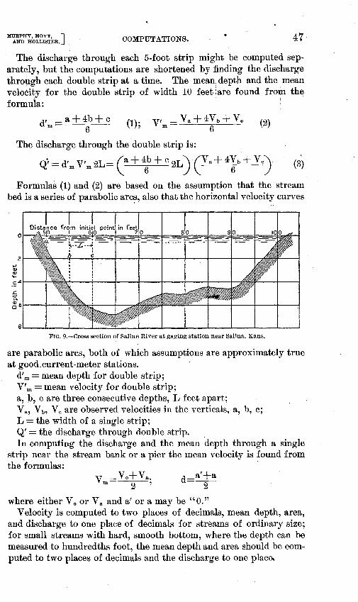
MURPHY, HOYT, J AND HOLLISTER._ COMPlJTATIONS. 47
The discharge through each 5-foot strip might be computed separately, but the computations are shortened by finding the discharge thro*gh each double strip at a time. The mean: depth and the .mean velocity for the double strip of width 10 feet :are found fron1 the formula:
d'm =a+ 4b + ~ 6
(1); V' m
The discharge through the .double strip is:
(2)
Q; = d'm V'm2L= ca+ 4: + c 2L) (Va+ 4~b + Vc) \.
(3)
Formulas (1) and (2) are based on the assumption that the stream bed is a series of parabolic arc~, also that the horizontal velocity curves
~ Q) (I) .... -~41---i,--'
~
b. ~61---+---
FIG. 9.-Cross section of Saline River at gaging station near Salina, Kans.
are parabolic arcs, both of which assumptions are approximately true at good.current-meter stations.
d'm =mean depth for double strip; V' m = mean velocity for double strip; a, b, care three consecutive depths, L feet apart; Va, Vb, Vc are observed velocities in the verticals, a, b, c; L =the width of a single strip; Q' =the discharge through double strip. In computing the discharge and the mean depth through a single
strip near the stream bank or a pier the mean velocity is found from the formulas:
a'+a d=--2
where either Yo or V a and a' or a may be "0." Velocity is computed to two places of decimals, mean depth, area,
and discharge to one place of decimals for streams of ordinary size; for small streams with hard, smooth bottom, where the depth can be measured to hundredths foot, the mean depth and area should be computed to two places of decimals and the discharge to one plac~
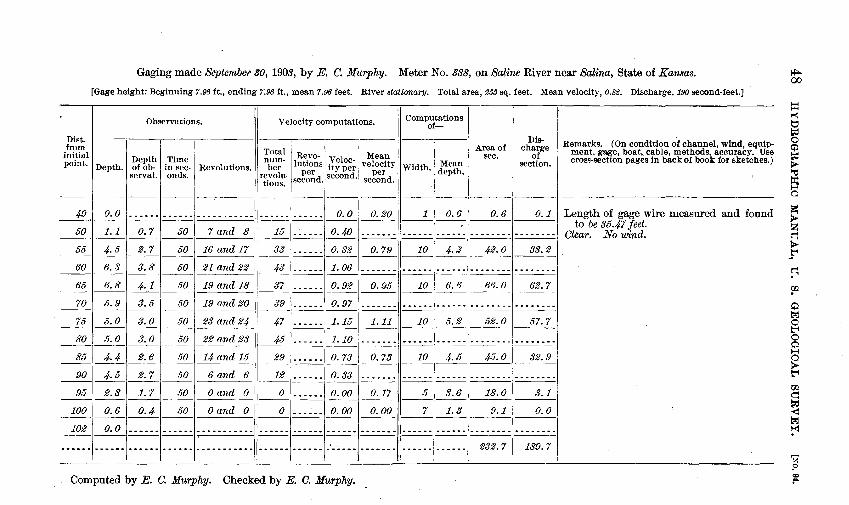
Gaging made September 30, 1903, by E. C. Murphy. Meter No. 388, on Saline River near Salina, State of Kansas.
(Gage height: Beginning 7.96 ft., ending 7.96 !t., mean 7.96 feet. River stat·ionary. Total area, 233 sq. feet. Mean velocity, 0.82. Discharge, 190 second-feet.]
Dist. from
Observations.
initial! I Depth I Time point. Depth. of ob- in sec- I Revolutions.
servat. onds.
Velocity computations. Computations of-
ber lutwns ity per velocity II Width I Mean per per · depth.
Area of sec.
Discharge
of section.
Remarks. (On condition of channel, wind, equipment, gage, boat, cable, methods, accuracy. Use cross-section pages in back of book for sketches.) ~~~~ I R~vo-~ Veloc- i Mea!l
r~i6~~- second. second. second.
---;;----;; = =~~----- ·----.I== ----;;1
1 o. eo ~--1-~ o. 6 1 o. 61 o. 1 1 Length of gage wire measured and found -------- --------- ------. to be 35.47 feet. __!!!__ ____!:__!:__ ___2:.!_ _!!!___ 7 and 8 I _!§__ _:_:_:.:__:__:_ 0. 40 :__:_:__:__:_:_ /.:..:__:__:_:_: _:__:_:_:__:_:_!-------- --------I Clear. No wind.
55 4. 5 2. 7 50 116 and 17 33 1 •••... 1 0. 82 0.79 10 I 4.2 42.0 33.2 ------------1
----II _____±!_I _:_:_:.:_:_:_1 1· 06 I~ 11_:__:_:_:_:_:_1~1--- .••• -,:_:_:__:_:__:_: 6.6 66.0 0.95 37 1······1 0.92 1----11--1--1--~1 -- .. 1 11--- ---
10 62.7
__ , -----II_!!!___J:._:_:_:_:_:_i o. 97 I :__:_:__:__:_:_j[.:..:__:_:_:_:l~l~l:_:_:__:_:__:_: 47
1
. ____ .
1
1.15l 1. 11 II 10 I 5. 2! 52. o I 57. 7 __ , 1(---------- ---____j§_ _:_:_:.:__:__:_ 1.10 ~' _:__:_:_:_:__:. :_:_:_:_:_: ....... ·,·· •• -.-.
29 1 •••••• 1 0. 73 0.73 10 I 4.5 45.0 32.9
12 1-. ___ .1 o. 33 1~ 11 :_:_:_:_:_:1_:__:_:_:_:_:_1------- -1:_:_:__:_:__:_: --1 11----1--
0.00
--~--~ 11 _o_1_:__:_:_:_:_:_
1 0.00 1~11_5_1~1 18.0 I 3.1
1
1.3 9.1 0.0 o 1- .. ~.-I o. oo 7 ---1 11---------1---11---1 1----
--I ll:_:_:_:_:_:[.:.:.:..:..::..j.:._:__:_:_:_:_j~ll.:.:..:.:::_:l".--- .,. -- ••• - .,. --- ••••
232.7 189.7
Computed by E. C. Murphy. Checked by E. C. Murphy.
~ 00
~ ~
~ 0
~ > ; a Is: ~ 2l ~ >-~
~ rn ~ t;.:j
~ 0 ~ H a ~ ~
U1 ~
~ t;.:j
~
z 9
if

MURPHY, HOYT, J AND HOLLISTER. COMPUTATIONS.
If the district hydrographer desires he can compute discharge from the formula given on page eighty-six of "Instructions relating to the work of the United States Geological Survey, May 1, 1903,-" n,amely,
(with altered symbols)~ Q' =(a+~+ 0 ) LV b. The letters have the
same meaning as in the formula on page 47, except that Q' is the discharge through the vertical section extending from halfway between a and b to halfway between b and c.
It sometimes happens that the velocity becomes very small or "O" in some parts of the cross-section at a station, as in the case of the Salina station for the part from 95 to 102 feet from the initial point. This area of small or "O" velocity is sometimes neglected in computing the cross-sectional area and the mean velocity. Mean velocity obtained in this way is sometimes misleading, because it may make a. section in which the true velocity is only 0.3 or 0.4 foot per second (a section that should not be used) appear to have a velocity of half a foot or more per second. There is danger, too, that if this low velocity area is neglected in computing mean velocity, no attention will be given to measuring those velocities, and thus an error will be introduced into the discharge. It has been decided to include the whole area in the column headed '"area" in computing mean velocity.
COMPUTATIONS OF VERTICAL-VELOCITY CURVES AND COEFFICIENTS.
The method of making vertical-velocity-curve observations is de-. scribed on page 20, the form for recording the observations is given on page 50, the velocities in column 4 are plotted as shown on page 51, the depth of center·of meter below the surface being used as ordinates and velocities as abscissas. A smooth curve is drawn among them making a graphic adjustment of the observations. The mean abscissa of this curve is the mean velocity in this vertical. The depth below the surface of the thread of mean velocity is the ordinate which corresponds to the mean abscissa or to the computed mean velocity.
To compute the mean velocity from the vertical-velocity curve, divide the depth into from 5 to 10 equal parts and write the velocity at the center of each part in column 6, headed "'velocity from curve." Find the sum of these and divide by the number of parts; the quotient is the mean velocity in that vertical.
It is often more convenient, when the depth is a number of feet and a fraction, as 8.3 feet, to divide the depth into 8 parts of a foot width, and a part of 0.3 foot width. Then the velocity to enter in column 6 for the narrow part is 0.3 of the velocity at the center of it.
The velocities at a point 1 foot below the surface, mid-depth, and bottom are read directly from the vertical-velocity curve, and recorded in column 8. The'' coefficients for reducing to mean velocity," required in column 9, are obtained by dividing the mean velocity by each of the velocities in column 8.
IRR 94-04-4

50 HYDROGRAPHIC MANUAL, U. S. GEOLOGICAL SURVEY. [NO. 94.
Vertical-velocity measurement made November 2, 1903, by E. C. Murphy, meter No. 585 feet from initial point
Gage height: beginning 3.08 ft., ending 3.08 ft.,
FIELD NOTES. DATA FROM CURVE AND COMPUTATION.
Depth of Number Coe:ffi-center of revolu- Number Velocity Middle of Velocity cient for meter be- revolu- horizon- Point in low sur- tions per tions per per tal sec- from vertical. Velocity. reducing face in 50 sec- second. second. tion. curve. to mean
feet. onds. velocity.
---
{ 61-61 } 0.5 1.22 2.85 1 2.85 0. 6depth. 2.45 1. 01 61-62
---
{ 59 } 1ft. below 1.5 1.16 2.71 2 2.78 surface. 2.82 0.88 57
{ 58 } 2.5 1.19 2.79 3 2.72 Bottom. 1.40 1.77 61
3.5 { 54 } 1. 09 Mid depth. 2.58 4 2.62 2.57 0.96 55
{ 57 } 4.5 1.11 2.60 5 2.50 54
5.5 { 45 } 2.25 .96 6 2.35 Depth of { J,.S ft., 51
me!ln ve- 56 per cent
6.5 { 44 } loCity= of depth. .92 2.16 7 2.16 48
7.5 { 38 } .77 1.82 8 1.82 39
8.0 9
10
Total •• 19.80 Computed by Brundage.
Mean_ 2.48 Checked by Marsh.
Fall of river,-- feet per mile.
Remarks.-(Wind conditions. Character of stream bed. Roughness under surface of ice, etc.)

MURPHY, HOYT, J AND HOLLISTER. OOMPUTATIONS. 51
388, on Susquehanna River, at Harrisburg, State of Pennsylvania. Measurements at for soundings. Depth 8 ft.
mean 3.08 ft. Channel open. Thickness of ice, - ft.
1/ ~ 3 I
II/'~ 1/r-J 1- 'li'lt., rip P.f" I ([ I
..... f2-;-~~
CDj ,. 12 I
I
(~
I I
II ' ct
ih
~\ ~ !2-:-~·~ J ~,
I ~ r--,- ~ 12.!45 1- --- ~()
' :- I
~ u I :\
!6 I
·f£:
I J
~
-~ 'Ta I-"' I •
'-·
..
FIG. 10.-Vertica I-velocity curve.
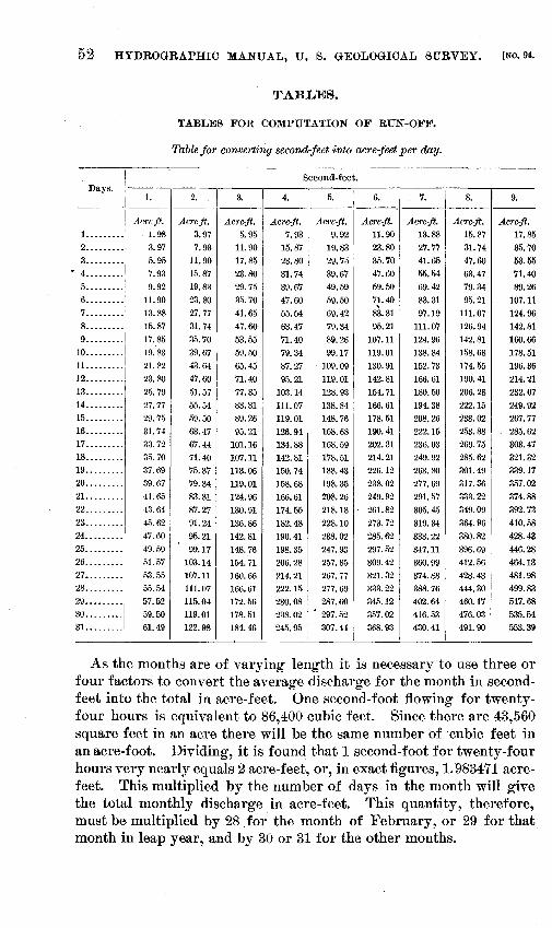
52 HYDROGRAPHIC MANUAL, U. B. GEOLOGICAL SURVEY. [No. 94.
TABLES.
TABLES FOR COMPUTATION OF RUN-OFF.
Table for convert·ing secondjeet into acre-feet per day.
Second-feet. Days.
I 1. 2. 3. 4. 5. 6. 7. 8. 9. ------------'---. ---------
Acre-ft. Acre-ft. Acre-ft. Acre-ft. Acre-ft. Acre-ft. Acre-ft. Acre-ft. Acre-ft. 1 •••...... . l. 98 3.97 5.95 7.93 9.92 11.90 13.88 15.87 17.85 2 ......... 3.97 7.93 11.90 15.87 19.83 23.80 27.77 31.74 35.70
:~~~::::J 5.95 11.90 17.85 23.80 29.75 35.70 41.65 47.60 53.55 7.93 15.87 23.80 31.74 39.67 47.60 55.54 63.47 71.40
··········j 9.92 19.83 29.75 39.67 49.59 59.50 69.42 79.34 89.26 6 ..•...... 11.90 23.80 35.70 47.60 59.50 71.40 83.31 95.21 107.11 7 •........ 13.88 27.77 41.65 55.54 69.42 8S.31 97.19 111.07 124.96 8 ......... 1 15.87 31.74 47.60 63.47 79.34 95.21 111.07 126.94 142.81 9 ......... 1 17.85 35.70 53.55 71.40 89.26 107.11 124.96 142.81 160.66
10 ......... 1
I 19.83 39.67 59.50 79.34 99.17 119.01 138.84 158.68 178.51
11 ......... : 21.82 43.64 65.45 87.27 109.09 130.91 152.73 174.55 196.36 12 •........ I 23.80 47.60 71.40 95.21 119.01 142.81 166.61 190.41 214.21 13 .•....... 25.79 51.57 . 77.35 103.14 128.93 154.71 180.50 206.28 232.07 14 .....•... 27.77 55.54 83.31 111.07 138.84 ' 166.61 194.38 222.15 249.92 15 ......... 29.75 59.50 89.26 119.01 148.76 I 178.51 208.26 238.02 267.77 16 ......... 31.74 63.47 95.21 126.94 158.68 190.41 222.15 253.88 285.62 17 •........ 33.72 67.44 .101.16 134.88 168.59 202.31 236.03 269.75 303.47 18 ........• 35.70 71.40 107.11 142.81 178.51 214.21 249.92 285.62 321.32 19 ......... 37.69 75.37 113.06 150.74 188.43 226.12 263.80 301.49 339.17 20 ......... 39.67 79.34 119.01 158.68 198.35 238.02 277.69 317.36 357.02 21. ........ 41.65 83.31 124.96 166.61 208.26 249.92 291.57 333.22 374.88 22 ......... 43.64 87.27 130.91 174.55 218.18 261.82 305.45 349.09 392.73 23 ......... 45.62 91.24 136.86 182.48 228.10 273.72 319.34 364.96 410.58 24 .•....... 47.60 95.21 142.81 190.41 238.02 285.62 333.22 380.82 428.43 25 ......... 49.59 99.17 148.76 198.35 247.93 297.52 347.11 396.69 446.28 26 ......... 51.57 103.14 154.71 206.28 257.85 309.42 360.99 412.56 464.13 27 •........ 53.55 107.11 160.66 214.21 267.77 321.32 374.88 428.43 481.98 28 ......... , 55.54 111.07 166.61 222.15 277.69 333.22 388.76 444.30 499.83 29 •........ 1 57.52 115.04 172.56 230.08 287.60 345.12 402.64 460.17 517.68
30 ......... 1 59.50 119.01 178.51 238.02 297.52 357.02 416.53 476.03 535.54 31 •........ 61.49 122.98 184.46 245.95 307.44 368.93 430.41 491.90 553.39
As the months are of varying length it is necessary to use three or four factors to convert the average discharge for the month in secondfeet into the total in acre-feet. One second-foot flowing for twentyfour hours is equivalent to 86,400 cubic feet. Since there are 43,560 square feet in an acre there will be the !:lame number of cubic feet in an acre-foot. Dividing, it is found that 1 second-foot for twenty-four hours very nearly equals 2 acre-feet, or, in exact figures, 1. 983471 acrefeet. This multiplied by the number of days in the month will give the total monthly discharge in acre-feet. This quantity, therefore, must be multiplied by 28 for the month of February, or 29 for that month in leap year, and by 30 or 31 for the other months.

Mt1RPHY, HOYT, J AND HOLLISTER,
• TABLES. 53
For the month of February when it has 28 days the factor to be used is 55.537188. For convenience in computation this factor multiplied from 1 to 9 is given in the following table: ·
1 - ----- - - -- - - - ----- - - - - - - -- - - - ---- -- -- - - - -- - - - ----- ------ 55. 53719 2 - ----- -----. - ----- ------ - ---- - - ----- - -- - -- - ---- --------- 111. 07 438 3 -------------------------- ------------ _.----- ------------ 166. 61156 4 ---- ---------- - - - - - - ---- -- - -- --- - ---- - - - ---- - - - - -- ------ 222. 14875 5 ________________________________________________________ 277.68594
6 - -- - - - - - -- - - - - - - - - - - -- -- -- - - - - - - - - - - - - - - - - -- - - - - - - -- - - -- 333. 22313 7 -- -- - ----- --- - - - ------ - -- - - - - - - -- - - -- - - --- -- -- ---- - ----- 388. 76032 8 - - - - - - - - - -- - - - - - - - - - . - - - - - - - - - -- - - - -- - - - - - - - - - - - - - - - - - -- 444. 29750 9 - - - -- - - - - -- - - - - . -- - - -- - -- - - - - - - - - - - - - -- - - - - - - - - - - - - - - -- - 499. 83469
When February has 29 days the factor to be used is 57.520659. This when multiplied from 1 to 9 gives the following:
1 ---- -- - - - --- -- - - -- -- - -- - . - -- --- -- - - - - - - - ---- --- - ---- ---- 57. 52066 2 - -- - - - - - - - - - - - - - - -- - - - - - - - - - - - - - - - - - - - - - - - - - - -- - -- - -- - - - 115. 04132
. 3 ------ - ----- - - ---- ------ - ----- ------ ----- - ------- --- -- - - 172. 56198 4 - - - - - - - - - -- - - - - - - - - - - - - - - - - - - - - - - - - - -- - - - - -- - --. - - - - _-- - - 230. 08264 5 ------ - ----- - -- --- - - -- ------ ------ ----- -----. - . ----- -- - - 287. 60330 6 ---- ---- - ---- --- -------- ---- - - - - ---- ---- ---- ------ ------ 345. 12395 7 - - - - - - - - - - - - - -- - - . - -- - -- - - - - - - - - - - - - - - - - -- -- -- - - - - - -- - - - 402. 64461 8-------------------------------------------------------- 460.16527 9-------------------------------------------------------- 517.68593
For the months containing 30 days, viz, April, June, September, and November, the factor to be used is 59.504130. This, when multiplied by the unit figures, gives the following results:
1-------------------------------------------------------- 59.50413 2-------------------------------------------------------- 119.00826 3-------------------------------------------------------- 178.51239 4-----·-------------------------------------------------- 238.01652 5-------------------------------------------------------- 297.52065 6 .... ---------------------------------------------------- 357.02478 7-------------------------------------------------------- 416.52891 8-------------------------------------------------------- 476.03304 9-------------------------------------------------------- 535.53717
For the months containing 31 days, viz, January, March, May, July, August, October, and December, the factor to be used is 61.487601. This, when multiplied by the unit figures, gives the following results:
1-------------------------------------------------------- 61.48760 2 .... ~--------------------------------------------------- 122.97520 3 - -- - - - . -- --- - - - - - - -- - . - -- - - - - - -- - - - - - -- - - -- - - -- - - - - - -- - - 184. 46280 4 - - - - - - - - - - - - - - - - - --- . - - - -- - - . - - - - - - - - - -- - ---- . - - - -- -- - - - - 245. 95040 5-------------------------------------------------------- 307.43800 6 - -- - - - - - - -- . - - - - - - - - - - - - --- - - ... - - - - - - - - -- --- ---- --- --- - -- - .. 368. 92561 7 ---- ------ ---------- -- -- ---- --- _·-- _-_-. -- _'_ ---- _'_ -------- 430. 41321 8 ------ - - ---- - - ----- ------ ---------- ---- -_--------- ---- ---- 491. 90081 9-----------~-------------------------------------------~ 553.38841

-
o.
o ______ ------------1 ______
555.372 2 ...... 1,110.744 3 ______ 1,666.116 4 ...... 2, 221.488 5 ...•.. 2,776.859 6 ...••• 3,332.231 7 ...... 3,887.603 8 .....• 4,442.975 9 ...... 4,998.347
10 ...... 5,553.719
o.
o ______ ···---------• 1...... 575.207 2 ...... 1,150.413
3.-- -·- 1, 725.620 4...... 2,300.826 5...... 2,876.033 6...... 3, 451.240
Table for converting second-feet into acre-feet per month of twenty-eight days.
I
.. I 2. 3. 4. 5. 6. 7.
55.537 111.074 166.612 222.149 277.686 333.223 388.760 610.909 666.446 721.983 777.521 833.058 888.595 944.132
1,166.281 1, 221.818 1,277.355 1,332.892 1,388.430 1,443.967 1,499.504 1, 721.653 1,777.190 1,832.727 1,888.264 1,943.802 1,999.339 2,054.876 2,277.025 2,332.562 2,388.099 2,443.636 2,499.173 2,554.711 2,610.248 2,832.396 2,887.934 2,943.471 2,999.008 3,054.545 3,110.082 3,165.620 3,387.768 3,443.306 3,498.843 3,554.380 3,609.917 3,665.454 3, 720.992 3,943.140 3,998.678 4,054.215 4,109. 752 4,165.289 4,220.826 4,276.363 4,498.512 4,554.049 4,609.587 4,665.124 4,720.661 4, 776. 198 4, 831. 735 5,053.884 5,109.421 5,164.958 5,220.496 5,276.033 5, 331.570 5,387.107 5,609.256 5,664.793 5,720.330 5,775.868 5, 831.405 5,886.942 5,942.479
Table for converting second-feet into acre-feet per month of twenty-nine days.
1.
57.521 632.727
1,207.934 1,783.140 2,358.347 2,933.554 3,508.760
2.
115.041' 690.248
1,265.454 1,840.661 2,415.868 2, 991.074 3,566.281
3.
172.562 747. 768
1,322.975 1,898.182 2,473.388 3,048.595 3,623.802
4.
230.083 805.289
1,380.496 1,955.702 2,530.909 3,106.116 3, 681.322
5.
287.603 862.810
1,438.016 2,013.223 2,588.430 3,163.636 3, 738.843
6.
345.124 920.330
1,495.537 2,070. 744 2,645.950 3, 221. 157 3,796.363
7.
402.645 977.851
1,553.058 2,128.264 2,703.471 3,278.678 3,853.884
8. 9.
444.298 499.835 999.669 1,055.206
1,555.041 1,610.578 2,110.413 2,165.950 2,665.785 2, 721.322 3, 221. 157 3,276.694 3,776.529 3,832.066 4, 331.901 4,387.438 4,887.272 4,942.810 5,442.644 5, 498.182 I
5,998.016 6,053.553
8. 9.
460.165 517.686 1,035.372 1,092.892 1,610.578 1,668.099 2,185.785 2,243.306 2,760.992 2,818.512 3,336.198 3,393.719 3,911.405 3,968.925
I
01 ~
til ~ t::;! ~ 0 Cj:l ~ b> 1-d J:I: H a :=:: b> ~ ~ b>
_rt
~ r:p
Q t;1 0 ti 0 Cj) H a > t"f
• w q ~ < t.;Ej
~
~ <:C ~

7 ••...• 4,026.446 4,083.967 4,141.487 4,199.008 4,256.529 4,314.049 4,371.570 8 ...... 4, 601.653 4,659.173 4,716.694 4,774.215 4, 831.735 4,889.256 4,946.777 9 ______ 5,176.859 5,234.380 5, 291.901 5,349.421 5,406.942 5,464.463 5, 521.983
10 ...... 5,752.066 5,809.586 5,867.107 5,924.628 5,982.148 6,039.669 6,097.190 ----------------
Table for converting second-feet into acre-feet per. month of thirty days.
0. 1. 2. 3. 4. 5. 6.
o ______ ------------ 59.504 119.008 178.512 238.016 297.521 357.025
1 ...... 595.041 654.545 714.050 773.554 833.058 892.562 952.066 2 ______ 1,190.083 1,249.587 1,309.091 1,368.595 1,428.099 1,487.603 1,547.107 3 ...... 1,785.124 1,844:628 1,904.132 1,963.636 2,023.140 2,082.644 2,142.149 4 ...... 2,380.165 2,439.669 2,499.173 2,558.678 2,618.182 2,677.686 2, 737.190 5 ...... 2,975.206 3,034. 711 3,094.215 3,153.719 3,213.223 3,272. 727 3,332.231 6 ...... 3,570.248 3,629.752 3,689.256 3,748. 760 3,808.264 3,867. 768 3,927.272 7 ...... 4,165.289 4,224.793 4,284.297 4,343.801 4,403.306 4,462.810 4,522.314 8 ...... 4,760.330 4, 819._834 4,879.339 . 4,938.843 4,998.347 5,057.851 5,117.355 9 ...... 5,355.372 5,414.876 5,474.380 5,533.884 5,593.388 5,652.892 5,712.396
10 ...... 5,950.413 6,009.917 6,069.421 6,128.925 6,188.430 6,247.934 6,307.438 -------- -- --------
4,429.091 4,486.611 5,004.297 5, 061. 818 5,579.504 5,637.024 6,154.710 6,212.231
7. 8.
416.529 476.033 1,011.570 1,071.074 1,606.612 1,666.116 2, 201.653 2, 261.157 2, 796.694 2,856.198 3, 391.735 3, 451.240 3,986. 777 4,046.281 4, 581.818 4, 641.322 5,176.859 5,236.363 5, 771.901 5, 831.405 6,366.942 6,426.446
-- -
4,544.132 5,119.339 5,694.545 6,269.752
9.
535.537 1,130.578 1,725.620 2,320.661 2,915.702 3,510.744 4,105.785 4,700.826 5,295.868 5,890.909 ·6, 485.950
I>-~ z~ '='I:EI ~.:< t"'I:EI t"'O lil>< ,.,,., t;l-
~ L....J
8 p.. t:::d t"4 ~ '/.J
Ol Ol

Table for converting second-feet into acre1eet per month of thirty-one days.
0. 1. 2. 3. 4. 5. 6. 7.
o ______ ------------ 61.488 122.975 184.463 245.950 307.438 368.926 430.413
1 ______ 614.876 676.364 737.851 799.339 860.826 922.314 983.802 1,045.289 2. _____ 1,229.752 1, 291. 240 1,352.727 1,414.215 1,475.702 1,537.190 1,598.678 1,660.165 3 ______
1,844.628 1,906.116 1,967.603 2,029.091 2,090.578 2,152.066 2,213.554 2,275.041 4 ...... 2;459.504 2,520.992 2,582.479 2,643.967 2,705.454 2,766.942 2,828.430 2,889.917 5 ______ 3,074.380 3,135.868 3,197.355 3,258.843 3,320.330 3, 381.818 3,443.306 3,504.793 6 ____ ·- 3,689.256 3, 750.744 3,812.231 3, 873.719 3,935.206 3,996.694 4,058.182 4,119.669 7 ...... 4,304.132 4,365.620 4,427.107 4,488.595 4,550.082 4,611.570 4,673.058 4,734.545 8 ....•. 4,919.008 4,980.496 5, 041.983 5,103.471 5,164.958 5,226.446 5,287.934 5,349.421 9 ______
5,533.884 5,595.372 5,656.859 5, 718.347 5,779.834 5, 841.322 5,902.810 5,964.297 10 ...... 6,148.760 6,210.248 6, 271. 735 6,333.223 6,394. 710 6,456.198 6,517.686 6,579.173
---------------
8. 9.
491.901 553.388 1,106.777 1,168.264 1, 721. 653 1,783.140 2,336.529 2,398.016 2, 951.405 3,012.892 3,566.281 3,627.768 4, 181. 157 4,242.644 4,796.033 4,857.520 5,410.909 5,472.396 6,025.785 6,087.272 6,640.661 6,702.148
01 ~
Ill 1-<l tj td 0 ~ td t;J;..
~ ~
a :=:: > !Z Cl t;J;..
~
~ rp
~ t%j 0 t-t 0 ~ 1-1 a t;J;.. t-t
00
~ M I'<!
z ?
!f

MURPHY, HOYT, ] AND HOLLISTER. TABLES. 57
The depth of run-off over the drainage basin is usually computed in inches for convenience of comparison with the depth of rainfall, which is almost invariably given in that unit. This depth can most conveniently be computed from the run-off per square mile by computation based upon the num her of days in each month and the relation between the rate of flow and the depth in inches for this quantity were it held during the given number of days. One second-foot for twenty-four hours is equivalent to 86,400 cubic feet in one day. In other ~ords, 1 cubic foot per -second run-off from 1 8quare' mile would, if held upon this area, cover it to a depth represented by dividing 86,400 by the number of square feet in a mile, 27,878,400, or 5,280 squared. Completing this division, it is found that 1 secondfoot for one day is equivalent to a body of water covering 1 square mile 0.003099174 feet, or 0.037190088 inch. Multiplying this by the · number of days in a month gives the following factors:
28 days. ______________________ ~________________________ 1. 041322528
29 days------------------------------------------------ 1.078512604 30 days.----------------------------------------------- 1.115702680 31 days------------------------------------------------ 1.152892756

Table for converting run-off ·in second-feet per square mile into depth in inches per month of twenty-eight days.
0.0. 0.1. 0.2. 0.3. 0.4. 0.5. 0.6. 0.7. 0.8.
1 ______ 1. 0413 1.1454 1. 2496 1. 3537 1. 4578 1. 5620 1. 6661 1. 7702 1. 8744 2 ______
2.0826 2.1868 2.2909 2.3950 2.4992 2.6033 2.7074 2.8116 2.9157 3 ...... 3.1240 3.2281 3.3322 3.4364 3.5405 3.6446 3.7488 3.8529 3.9570 4 ...... 4.1653 4.2694 4.3736 4.4777 4.5818 4.6859 4.7901 4.8942 ' 4. 9983 5 ...... 5.2066 5.3107 5.4149 5.5190 5.6231 5.7273 5.8314 5.9355 6.0397 6 ...... 6.2479 6.3521 6.4562 6.5603 6.6645 6.7686 6.8727 6.9769 7.0810 7 ______ 7.2892 7.3934 7.4975 7.6016 7.7058 7.8100 7.9140 8.0182 8.1223 8 ...... 8.3306 8.4347 8.5388 8.6430 8.7471 8.8512 8.9554 9.0595 9. 1636 9 ...... 9.3719 9.4760 9.5802 9.6843 9.7884 9.8926 9.9967 10.1008 10.2050
10 •••••• 10.4132 10.5174 10.6215 10.7256 10.8297 10.9339 11.0380 11.1421 11.2463 ~---- ----------- ---- ------ ----
Table for converting run-off in second-feet per square mile into depth in inches per month of twenty-nine days.
0.0. 0.1. 0.2. 0.3. 0.4. 0.5. 0.6. 0.7. 0.8.
1. ----· 1.0785 1.1864 1. 2942 1. 4021 1. 5099 1. 6178 1. 7256 1. 8335 1. 9413 2 ______ 2.1570 2.2649 2.3727 2.4806 2.5884 2.6963 2.8041 2.9120 3.0198 3 ...... 3.2355 3.3434 3.4512 3.5591 3.6669 3.7748 3.8826 3.9905 4.0983
4.----- 4.3140 4.4219 4.5298 4.6376 4.7454 4.8533 4.9612 5.0690 5.1768 5 •••••• 5.3926 5.5004 5.6083 5.7161 5.8240 5.9318 6.0397 6. 1475 6. 2554 6 ....•• 6.4711 6.5789 6.6868 6.7946 6.9025 7.0103 7.1182 7.2260 7.3339
7 -----· 7.5496 7.6574 7. 7653 7.8731 7.9810 8.0888 8.1967 8.3045 8.4124
0.9.
1. 9785 3.0198 4.0612 5.1025 I
6.1438 I
I 7.1851 I
8.2264 9.2678
10.3091
11.3504 I
0.9.
2.0492 3.1277 4.2062 5.2847 6.3632 7.4417 8.5202
01 00
P=l 1-1 t::J P:l 0 0 to II>-
~ 1-4 a ti:(
~ q ~ t'i
~ r:T.1
0 tzj 0 t:"+
·8 H a I> t'i
r:JJ ct P:l <f t:s:j
~
~ ~
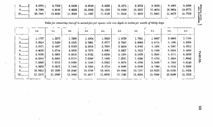
8 •••.•• 8.6281 8.7359 8.8438 8.9516 9.0595 9.1674 9.2752 9.3830 9 ...••. 9.7066 9.8145 9.9223 10.0302 10.1380 10.2459 10.3537 10.4616
10 ••••.. 10.7851 10.8930 11.0008 11.1087 11.2165 11.3244 11.4322 11.5401
Table for converting run-off in second-feet per square mile into depth in inches per month of thirty days.
0.0. 0.1. 0.2. 0.3. 0.4. 0.5. 0.6. 0.7.
1 ...••. 1.1157 1. 2273 1. 3388 1. 4504 1. 5620 1. 6736 1. 7851 1. 8967 2 ...••• 2.2314 2.3430 2.4545 2.5661 2.6777 2.7893 2.9008 3.0124 3 .•.... 3.3471 3.4587 3.5702 3.6818 3.7934 3.9050 4.0165 4.1281 4 ...... 4.4628 4.5744 4.6859 4.7975 4.9091 5.0207 5.1322 5.2438 5 ••.... 5.5785 5.6901 5.8016 5.9132 6.0248 6.1364 6.2479 6.3595
6. ····- ·6.6942 6.8058 6.9174 7.0289 7.1405 7.2521 7.3636 7.4752 7 ...... 7.8099 7.9215 8.0330 8. 1446 8.2562 8.3678 8.4793 8.5909 8 •..... 8.9256 9.0372 9.1488 9.2603 9.3719 9.4835 9.5950 9. 7066 9 ...... 10.0413 10.1529 10.2645 10.3760 10.4876 10.5992 10.7107 10.8223
10 .••... 11.1570 11.2686 11.3802 11.4917 11.6033 11.7149 11.8264 11.9380 ~---- - ------- -------
9.4909 9.5988 10.5694 10.6773 11.6479 11.7558
0.3. 0.9.
2.0083 2.1198 3.1240 3.2355 4.2397 4.3512 5.3554 5.4669
6.4711 6.5826 7.5868 7.6983 8. 7025 8.8140 9.8182 9.9298
10.9339 11.0454 12.0496 12.1612
I>-~ ~~ ~
~->< • t-<~ ~0 ~~ l;f" !;>:I
L......J
~ ~ tz=J 'fJ
Ot c:o
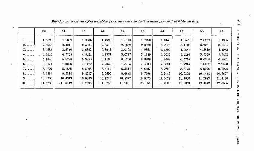
Table for converting run-off in second-feet per square mile into depth in inches per month of thirty-one days.
0.0. 0.1. 0.2. 0.3. 0.4. 0.5. 0.6. ' 0.7. 0.8.
1 ______ 1.1529 1.2682 1. 3835 1.4988 1.6140 1. 7293. 1.8446 1. 9599 2.0752
2 ...... 2.3058 2.4211 2.5364 2.6516 2.7669 2.8822 2.9975 3.1128 3.2281 3 ...... 3.4587 3.5740 3.6892 3;8045 3.9198 4.0351 4.1504 4.2657 4.3810 4 ...... 4. 6116 4. 7268 4.8421 4.9574 5.0727 5.1880 5.3033 5.4186 5.5339
5 ... ---- 5.7645 5.8798 5.9950 6.1103 6.2256 6.3409 6.4562 6. 5715 6.6868
6.----- 6.9174 7.0326 7.1479 7.2632 7.3785 7.4938 7.6091 7. 7244 7.8397 7 ...... 8.0702 8.1855 8.3008 8.4161 8.5314 8.6467 8.7620 8.8773 8.9926
8.----- 9.2231 9.3384 9.4537 9.5690 9.6843 9.7996 9.9149 10.0302 10.1454 9 ...... 10.3760 10.4913 10.6066 10.7219 10.8372 10.9525 11.0678 11.1830 11.2983
10 .•.... 11.5289 .11.6442 11.7595 11.8748 11.9901. 12.1054 12.2206 12.3359 12.4512
0.9.
2. 1905 3.3434 4.4963 5.6492 6.8021 7.9550 9.1078
10.2607 11.4136 12.5665
~ 0
l:d '< tj ~ 0· Ci:l· ~ ~
~ H' 0·
I( ~ z. ~ ~ S' ~ rp
~· t-;1· 0· ti' 0 Ci:l 1-t 0 p.. t"'
rt:J c= ~ ~ toj'
"<
z :?
~

MURPHY, HOYT, J AND HOLLISTER. TABLES.
MISCELLANEOUS TABLES.
Cubic feet into gallons.
1 cubic foot=1,.728 cubic inches= 1~i8gallons=7.4805194 gallons.
[In gallons.]
61
1 cubic foot............................ 7. 4805194 6 cubic feet ..........................•• 44.8831164 2 cubic feet ••••........... : .. ~..... . . . . 14. 9610388 7 cubic feet...... . • • • . • . . . . . . . . . • . . . . . . 52. 3636358 3 cubic feet ••••••..••.................. 22. 4415582 8 cubic feet ..........................•• 59.8441552 4 cubic feet .••••.•.•................... 29.9220776 9 cubic feet ..............•............. 67.3246746 5 cubic feet ....•••...•.............•... 37.4025970
0. -1. 1_2. _s.j_4. 5. 6. 7. 8. 9.
--0 ........... 7.48 14.96 22.44 29.92 37.40 44.88 52.36 59.84 67.32
1 74.81 82.28 89.77 97.25 104.73 112.21 119.69 127.17 134.65 142.13 2 149.61 157.09 164.57 172.05 179.53 187.01 194.49 201.97 209.45 216.94
3 224.42 231.90 239.38 246.86 254.34 261.82 269.30 276.78 284.26 291.74 4 299.22 306.70 314.18 321.66 329.14 336.62 344.10 351.58 359.06 366.55
5 374.03 381.51 388.99 396.47 403.95 411.43 418.91 426.39 433.87 441.35 6 448.83 456.31 463.79 471.27 478.75 486.23 493.71 501.19 508.68 516.16 7 523.64 531.12 538.60 546.08 553.56 561.04 568.52 576.00 583.48 590.96
8 598.44 605.92 613.40 620.88 628.36 635.84 643.32 650.81 658.29 665.77 9 673.25 680.73 688.21 695.69 703.17 710.65 718.13 725.61 733.09 740.57
Gallons into cubic feet.
1 United States liquid gallon=231 cubic inches=~cubic foot=0.133680555 cubic feet. 1,728
[In cubic feet.]
1 gallon • . . . . . . . . . . . . . . . . . . . . . . . . . . . . . . 0. 13368055 2 gallons ••......•............. :........ • 26736110 3 gallons.~..... . . . . . . . . . . . . . . . . . . . . . . . . . 40104165 4 gallons............... . . . . . . . . . . . . . . . . . 53472220 5 gallons............................... . 66840275
0. 1. 2. 3. 4.
- ---------------
0 ........... 0.1337 0. 2674 0.4010 0. 5347 1 1.3368 1.4705 1.6042 1. 7378 1.8715 2 2. 6736 2.8073 2. 9410 3.0746 3.2083 3 4.0104 4.1441 4. 2778 4. 4114 4.5451 4 5. 3472 5.4809 5. 6146 5. 7483 5. 8819 5 6.6840 6.8177 6. 9514 7.0851 7. 2187 6 8.0208 8.1545 8.2882 8.4219 8.5556 7 9.3576 9.4913 9.6250 9. 7587 9.8924 8 10.6944 10.8281 10.9618 11.0955 11.2292 9 12.0312 12.1649 12.2986 12.4323 12.5660
6 gallons ...•.• , ........................ 0. 80208330 7 gallons. . . . . . . . . . . . . . . . . . • . . . . . . . . . . • • . 93576385 8 gallons ............................... 1. 06944440 9 galloos ........•....•................. 1. 20312495
5. 6. 7. 8. 9.
---------------0.6684 0.8021 0. 9358 1. 0694 1.2031
2.0052 2.1389 2.2726 2.4062 2.5399
3.3420 3.4757 3.6094 3. 7430 3.8767
4. 6788 4.8125 4.9462 5.0799 5.2135
6. 0156 6.1493 6.2830 6.4167 6.5503 7.3524 7.4861 7.6198 7. 7535 7.8872 8.6892 8.8229 8. 9566 9.0901 9.2240
10.0260 10.1597 10.2934 10.4271 10.5608
11.3628 11.4965 11.6302 11.7639 11.8976 12.6996 12.8333 12.9670 13.1007 13.2344

62 HYDROGRAPHIC MANUAL, U. S. GEOLOGICAL ,SURVEY.
Feet per second into miles per hour.
1 foot per second=3,600 feet per hour=:::~ or ~miles per hour=0.681828.
[In miles per hour.]
[NO. 94.
1 foot per second . . . . . . . . . . . . • . • . . . . . . . . . . 0. 68182 6 feet per seconfl • . . . . • . • . . . • . . . . . . . . • . • • . 4. 09091
2 feet per second . . . . . . . . . . . . . . . . . . . . . . . . • 1. 36364 7 feet per second . • . . . . . . . . . . . . . . . . . . . • . . . 4. 77273
3 feet per second ..........•..........•..• 2. 04545
4 feet per second . • • • • • . . . . . . . . . . . . . • . . . . • 2. 72727
5 feet per second • • • . • • • • • . . . . • • . . . . • . . . • • 3. 40909
(See Smithsonian Meteorological Tables, No. 52.)
0. 1. 2. 3. 4.
8 feet per second • . . . . . . . . . . . . . . . . . . . . . . . . 5. 45455
7 feet per second ••.•••••........•...•.•.• 6.13636
5. 6. 7. 8. 9.
--------------------------------0 ............ 0.6818 1.3636 2.0455 2. 7273 3.4091 4.0909 4. 7727 5.4546 6.1364
1 6.8182 7.5000 8.1818 8.8637 9.5455 10.2273 10.9091 11.5909 12.2728 12.9546
2 13.6364 14.3182 15.0000 15.6819 16.3637 17.0455 17.7273 18.4091 19.0910 19.7728
3 20.4546 21.1364 21.8182 22.5001 23.1819 23.8637 24.5455 25.2273 25.9092 26.5910
4 27.2728 27.9546 28.6364 29.3183 30.0001 30.6819 31.3637 32.0455 32.7274 33.4092
5 34.0910 34.7728 35.4546 36.1365 36.8183 37.5001 38.1819 38.8637 39.5456 40.2274
6 40.9092 41.5910 42.2728 42.9547 43.6365 44.3183 45.0001 45.6819 46.3638 47.0456
7 47.7274 48.4092 49.0910 49.7729 50.4547 51.1365 51.8183 52.5001 53.1820 53.8638
8 54.5456 55.2274 55.9092 56.5911 57.2729 57.9547 58.6365 59.3183 60.0002 60.6820
9 61.3638 62.0456 62.7274 63.4093 64.0911 64.7729 65.4547 66.1365 66.8184 67.5002
Miles per hour into feet per second.
1 mile per hour=5,280 feet per hour=5•280 or~ feet per second=1.46667. 3,600 15
[In feet per second.]
1 mile per hour............... . . . . . • . . . . • . 1. 46667 2 miles per hour ...• ~ ....••..•...........• 2. 93333 3 miles per hour. . . . . . . . . . . . • . . . . . • . . . . . . • 4. 4000Q 4 miles per hour...... . • . . • . • . . . . . . . . . . . • . 5. 86667 5 miles per hour...... . . . • • . . . . . . . . .. . . . . . 7. 33333
(See Smithsonian Meteorological Tables, No 51.)
0. 1. 2. 3. 4.
6 miles per hour . • • . • • • . . • . . . . . . . • . . • . . • • 8. 80000 7milesperhour ...••••••••••..•••••••••• 10.26667 8 miles per hour ......................... 11.73333 9 miles per hour ......................... 13.20000
5. 6. 7. 8. 9 ..
--------------------------------
0 -··--···· 1.4667 2. 9333 4.4000 5.8667 7.3333 8.8000 10.2667 11.7333 13.2000
1 14.6667 16.1333 17.6000 19.0667 20.5333 22.0000 23.4667 24.9333 26.4000 27.8667
2 29.3333 30.8000 32.2667 33.7333 35.2000 36.6667 38.1333 39.6000 41.0667 42.5333
3 44.0000 45.4667 46.9333 48.4000 49.8667 51.3333 52.8000 54.2667 55.7333 57.2000
4 58.6667 60.1333 61.6000 63.0667 64.5333 66.0000 67.4667 68.9333 70.4000 71.8667
5 73.3333 74.8000 76.2667 77.7333 79.2000 80.6667 82.1333 83.6000 85.0667 86.5333
6 88.0000 89.4667 90.9333 92.4000 93.8667 95.3333 96.8000 98.2667 99.7333 101.2000
7 102.6667 104.1333 105.6000 107.0667 108.5333 110.0000 111.4667 112.9333 114.4000 115.~67 8 117.3333 118,8000 120.2667 121.7333 123.2000 124.6667 126.1333 127.6000 129.0667 130.5333
9 132.0000 133.4667 134.9333 136.4000 137.8667 139.3383 140.8000 142.2667 143.7333 145.2000

MURPHY, HOYT, ] AND HOLLISTER, TABLES. 63
Second-feet per day into millions of gallons.
1 second-foot, or 7.4805194 gallons per second for 1 day, or 86,400 seconds=646,316.87616 gallons.
[In gallons.]
1 second-foot for 24 hours ••....... _ _ 646,316.87 6 second-feet for 24 hours .......• _ .. 3, 877, 901.26 2 second-feet for 24 hours ........... 1, 292,633. 75 7 second-feet for 24 hours ......•.... 4, 524,218.13 3 second-feet for 24 hours •.......... 1, 938,950.63 8 ·second-feet for 24 hours ..... ___ ... 5, 170,535.01 4 second-feet for 24 hours •.......... 2, 585,267. 50 9 second-feet for 24 hours •... ___ . _ .. 5, 816, 851.88 5 second-feet for 24 hours • _ ..• _. ___ . 3, 231,584. 38
0. 5. 6. 7. 8. 9.
--~1. 1~2. 3. 1 4.
------
0 ............... 0. 6463 1.2926 1.9390 2.5853 3.2316 3.8779 4.5242 5.1705 5.8169 1 6.4632 7.1095 7. 7558 8.4021 9.0484 9.6948 10.3411 10; 9874 11.6337 12.2800
2 12.9263 13.5726 14.2190 14.8653 15.5116 16.1579 16.8042 17.4506 18.0969 18.7432 3 19.389/l 20.0358 20.6821 21.3285 21.9748 22.6211 23.2674 23.9137 24.5600 25.2084
4 25.8527 26.4990 27.1453 27.7916 28.4379 29.0843 29.7306 30.3769 31.0232 31.6695 5 32.3158 32.9622 33.6085 34.2548 34.9011 35.5474 36.1937 36.8401 37.4864 38.1327
6 38.7790 39.4253 40.0716 40.7180 41.3643 42.0106 42.6569 43.3032 43.9495 44.5959
7 45.2422 45.8885 46.5348 47.1811 47.8274 48.4738 49.1201 49.7664 50.4127 51.0590 8 51.7054 52.3517 52.9980 53.6443 54.2906 54.9369 55.5833 56.2296 56.8759 57.5222 9 58.1685 58.8148 59.4612 60.1075 60.7538 61.4001 62.0464 62.6927 63.3391 63.9854
Milrions of gallons into second-feet per d,ay.
1 million gallons per 24 hours 231•000•000 cubic feet per second, or 1.5472286 seoond-feet. 1728x86400
[In second-feet per 24 hours.J
1 million gallons _______ .... ________ --·· 1. 5472286 6 million gallons .... ___ ---_--_--.---__ 9.2833716 2 million gallons . _____ ... __ .. ___ .... _ . . 3. 0944572 7 million gallons ___ ... _ .. _ .. _. _ ...... _ 10. 8306002 3 million gallons •.... _ • _ .•. _ . _ _ _ _ _ _ _ _ _ _ 4. 6416858 8 million gallons . ___ . _______ . _ . _____ . _ 12. 3778288
4 million gallons .•... ____ ._: .. ··- ...... 6.1889144 9 million gallons .. __ .........•... _ .•.• 13. 9250574 5 million gallons ....•... _ .............• 7. 7361430
0. 1. 2. 3. 4. 5. 6. 7. 8. 9. ~------------------------------------
0 .......... 1.5472 3.0945 4.6417 6.1889 7. 7361 9.2834 10.8306 12.3778 13.9251 1 15.4723 17.0195 18.5667 20.1140 21.6612 23.2084 24.7556 26.3029 27.8501 29.3973 2 30.9446 32.4918 34.0390 35.5862 37.1335 38.6807 40.2279 41.7752 43.3224 44.8696 3 46.4169 47.9641 49.5113 51.0585 52.6058 54.1530 55.7002 57.2474 58.7947 60.3419 4 61.8891 63.4364 64.9836 66.5308 68.0781 69.6253 71.1725 72.7197 74.2670 75.8142 5 77.3614 78.9087 80.4559 82.0031 83.5503 85.0976 86.6448 88.1920 89.7393 91.2865 6 92.8337 94.3809 95.9282 97.4754 99.0226 100.5699 102.1171 103.6643 105.2115 106.7588 7 108.3060 109.8532 111.4005 112.9477 114.4949 116.0421 117.5894 119.1366 120.6838 122.2311 8 123.7783 125.3255 126.8727 128.4200 129.9672 131.5144 133.0617 134.6089 136.1561 137.7033 9 139.2506 140.7978 142.3450 143.8923 145.4395 146.9867 148.5339 150.0812 151.6284 153.1756

64 HYDROGRAPHIC MANUAL, U. 8. GEOLOGICAL SURVEY. [NO. 94.
Second-feet per day into acre-feet.
1 second-foot flow for one day=86,400 cubic feet=:·~~· or 1.983471 acre-feet. '
[In acre-feet.]
1 second-foot for 24 hours................ 1. 98347 2 second-feet for 24 hours................ 3. 96694 3 second-feet for 24 hours. • • • . . . . . • . • . • . . 5. 95041 4 second-feet for 24 hours.... . . . . . . . • . . . • 7. 93388 5 second-feet for 24 hours................ 9. 91735
6 second-feet for 24 hours ...••.•.•.•••••• 11.90083 7 second-feet for 24 hours ............•••• 13.88430 8 second-feet for 24 hours ....••.••••.•••• 15.86777 9 second-feet for 24 hours ................ 17.85124
0. 1. 2. 3. 4. 5. 6. 7. 8. 9.
--------------------~~-~--------
0 .......... 1.983 3.9ti7 5.950 7.934 9. 917 11.901 13.884 15.868 17.851
1 19.835 21.818 23.802 25.785 27.769 29.752 31.736 33.719 35.702 37.686 2 39.669 41.653 43.636 45.620 47.603 49.587 51.570 53.554 55.537 57.521 3 59.504 61.488 63.471 65.455 67.438 69.421 71.405 73.388 75.372 77.355 4 79.339 81.322 83.306 85.289 87.273 89.256 91.240 93.223 95.207 97.190
5 99.174 101.157 103.140 105.124 107.107 109.091 111.074 113.058 115.041 117.025
6 119.008 120.992 122.975 124.959 126.942 128.926 130.909 132.892 134.876 136.859 7 138.843 140.826 142.810 144.793 146.777 148.760 150.744 152.728 154.711 156.694 8 158.678 160.661 162.645 164.628 166.611 168.595 170.578 172.562 174.545 176.529
9 178.512 180.496 182.479 184.463 186.446 188.430 190.413 192.397 194.380 196.364
Acre-feet into -second-feet flow for 24 hours.
1 acre-foot each 24 hours=43,560 cubic feet each 86,400 seconds=!!::~. or~~ second-foot flow for
24 hours= 0.50416666 +. [In second-feet for 24 hours.]
1 acre-foot.... .. .. .. .. . . .. .. .. .. .. . . .. .. .. 0. 50417 6 acre-feet .. .. .. .. .. .. .. • .. . .. .. .. • .. .. .. • 3. 02500 2 acre-feet .••...•...•..................... 1. 00833 7 acre-feet •••.•....••.............•...••.• 3. 52917 3 acre-feet • .. . . . . . .. .. . . . . . . .. . .. . . .. . .. • • 1. 51250 8 acre-feet • • .. . . . . . . . . . .. . . . . . . .. . . . . . . . . . 4. 03334 4 acre-feet • • • • . . . . . . . . . . . . . . . . . . . . . . . . . . . . 2. 01667 9 acre-feet •••..•........ :. . . . . . . . . . . . . . . . . 4. 53750 5 acre-feet.... . • . • . • . . . . . . . . . . . . . . . . . . . . . • 2. 52084
0. 1. 2. 3. 4. 5. 6. 7. 8. 9.
------------------·--------------0 ········· 0.504 1.008 1.513 2.017 2.521 3.025 3.529 4.033 4.538 1 5.042 5.546 6.050 6.554 7.058 7.563 8.067 8.571 9.075 9.579 2 10.083 10.588 11.09'2 11.596 12.100 12.604 13.108 13.613 14.117 14.621 3 15.125 15.629 16.133 16.638 17.142 17.646 18.150 18.654 19.~58 19.663
4 20.167 20.671 21.175 21.679 22.183 22.688 23.192 23.696 24.200 24.704 5 25.209 25.713 26.217 26.721 27.225 27.729 28.234 28.738 29.242 29.746 6 30.250 30.754 31.259 31.763 32.267 32.771 33.275 33.779 34.284 34.788 7 35.292 35.796 36.300 36.804 37.309 37.813 38.317 38.821 39.325 39.829 8 40.334 40.838 41.342 41.846 42.350 42.854 43.359 43.863 44.367 44.871 9 45.375 45.880 46.384 46.888 47.392 47.896 48.400 48.905 49.409 49.913

MURPHY, HOYT, J AND HOLLISTER. TABLES. 65
Acre:feet into millions of gallons.
1 acre-foot=43,560 cubic feet= 43•560 X1•728, or 75•271•680, or 325,851.428 gallons.
231 231
[In gallons.]
Millions. Thousands. 1 acre-foot. .............. 0. 325851428 325. 9 2 acre-feet . . . . .. . .. .. . • . . . 65170286 651. 7 3 acre-feet • . • • . . . . . . . . . . . . 97755429 4 acre-feet ....••...••.... 1. 30340572 5 acre-feet . • • . . . • • • . • • . • . 1. 62925715
0. 1. 2. 3.
977.6 1,303.4 1, 629.3
4.
Millions. 6 acre-feet ....•.......... 1. 9.')510858 7 acre-feet ............... 2. 28096001 8 acre-feet ............... 2. 60681144 9 acre-feet ............... 2. 93266287
5. 6. 7. 8.
- ---------------------------
0 ............ 0.3259 0.6517 0. 9776 1. 3034 1. 6293 1. 955i 2.2810 2.6068
1 3.2585 . 3.5844 3. 9102 4.2361 4.5619 4.8878 5.2136 5.5395 5.8653 2 6.5170 5.8429 7.1687 7.4946 7.8204 8.1463 8.4721 8. 7980 9.1238
3 9. 7755 10.1014 10.4272 10.7531 11.0789 11.4048 11.7306 12.0565 12.3823 4 13.0341 13.3599 13.6857 14.0116 14.3374 14.6633 14.9891 15.3150 15.6408 5 16.2926 16.6184 16.9443 17.2701 17.5960 17.9218 18.2477 18.5735 18.8994 6 19.5511 19.8769 20.2028 20.5286 20.8545 21.1803 21.5062 21.8320 22.1579
7 22.8096 23.1354 23.4613 23.7871 24.1130 24.4388 24.7647 25.0905 25.4164
8 26.0681 26.3939 26.7198 27.0456 27.3715 27.6973 28.0232 28.3490 28.6749
Thousands. 1, 955.1 2, 281.0 2,606.8 2, 932.7
9.
---
2. 9327
6.1912 9.4497
12.7082 15.9667 19.2252
22.4837 25.7422
29.0007 9 29.3266 29.6524 29.9783 30.3041 30.6300 30.9558 31.2817 31.6075 31. 9334 132. 2592
Millions of gallons into acre-feet.
One million United States liquid gallons or 231 million cubic inches= 133,68(),555 cubic feet, or 133,680 43,560 =3.0688832 acre-feet.
[In acre-feet.]
1 million gallons ...................... 3.0688832 2 million gallons...................... 6.1377664 3 million gallons. __ .. ----- .... __ ... ___ 9. 2066496
4 million gallons . . . . • . . . . . . . . . . . . . . . . . 12. 2755328
5 million gallons .•..... --- .•.•........ 15.3444160
0. 1. 2. 3. 4.
6 million gallons . . . . . . . . . . . . . . . . • . . . . . 18. 4132992 7 million gallons . . . . . . . . . . . . . . . . . . . . . 21. 4821824 8 million gallons ...................... 24. 5510656 9 million gallons . . . . . . . . . . . . . . . . . . . . . . 27. 6199488 ·
5. 6. I 7. 8. 9. I
i
- ------------------------- -------
0 ............ 3.069 6.138 9.207 12.276 15.344 18.413 j 21.482 24.551 27.620 1 30.689 33.758 36.827 39.895 42.964 46.033 49.102 52.171 55.240 58.309 2 61.378 64.446 67.515 70.584 73.653 76.722 79.791 82.860 85.929 88.998 3 92.066 95.135 98.204 101.273 104.342 107.411 110.480 113.549 116.618 119.686 4 122.755 125.824 128.893 131.962 135.031 138.100 141.169 144.238 147.306 150.375 5 153.444 156.513 159.582 162.6.')1 1G5. 720 168.789 171.857 174.926 177.995 181.064 6 184.133 187.202 190.271 193.340 196.409 199.477 202.546 205.615 208.684 211.753 7 214.822 217.891 220.960 224.028 227.097 230.166 233.235 236.304 239.373 242.442 8 245.511 248.580 251.648 254.717 257.786 260.855 263.924 266.993 270.062 273.131 9 276.199 279.268 28:2.337 285.406 288.475 291.544 294. 613 I 297. 682 300.751 303.819
IRR 94-04-5

66 HYDROGRAPHIC M.ANUAL, U. S. GEOLOGICAL SURVEY. [NO. 94.
Second-feet into minute-gallons.
Factors: 1 cubic foot contains 1, 728 cubic inches; 1 gallon has a capacity of 231 cubic inches; 1 secondfoot equals [(1,728 + 231) x 60] gallons per minute, or 448.831164 minute-gallons.
[In gallons per minute.]
1 second-foot........................ 448.831164 2 second-feet .... _ ............•. _.... 897.662328 3 second-feet ....•.......••.•.....••• 1, 346.493492
4 second-feet ......................•• 1, 795. 324656 5 second-feet ....•.............••...• 2, 244.155820
0. 1. 2. 3. 4. ~
0 .............. 449 898 1,346 1, 795 1 4,488 4,937 5,386 5,835 6,284 2 8,977 9,425 9,874 10,323 10,772
3 13,465 13,914 14,363 14,811 15,260 4 17,953 18,402 18,851 19,300 19,749 5 22,442 22,890 23,339 23,788 24,237 6 26,930 27,379 27,828 28,276 28,725 7 31,418 31,867 32,316 32,765 33,214 8 35,906 36,355 36,804 37,253 37,702 9 40,395 40,844 41,292 41,741 42,190
6 second-feet ........................ 2, 692. 986984 7 second-feet ........................ 3, 141. 818148
8 second-feet ........................ 3, 590.649312 9 second-feet .......................• 4, 039.480476
5. _6·1_7. 8. 9.
2,244 2,693 3,142 3,591 4,039 6, 732 7,181 7,630 8,079 8,528
11,221 11,670 12,118 12,567 13,016 15,709 16,158 16,607 17,056 17,504 20,197 20,646 21,095 21,544 21,993
24,686 25,135 25,583 26,032 26,481
29,174 29,623 30,07:2 30,521 30,969
33,662 34,111 34,560 35,009 35,458
38,151 38,599 39,048 39,497 39,946
42,639 43,088 43,537 43,985 44,434
Minute-gallons "into second-feet.
Factors: 1 gallon contains 231 cubic inches; 1 cubic foot contains 1,728 cubic inches; 1 gallon per minute equals [(231 + 1,728)+ 60] second-feet, or .002,228,009, 2 second-feet.
[In second-feet.]
1 minute-gallon .. .. .. .. .. .. • .. .. .. . 0. 002, 228, 009 2 minute-gallons .. . .. .. .. . .. .. . .. .. . 004, 456,018 3 minute-gallons • . . . . . . . . . . . . . . . . . • . 006, 684, 028 4 minute-gallons .... __ .... _........ . 008, 912, 037
5 minute-gallons . • . . • • • . . . . . • . . . . . • • 011, 140, 046
0. 1. 2. 3. 4.
-- ---------------
0 .............. 0.0022 0. 0045 0. 0067 0.0089 1 0.0223 .0245 .0267 .0290 .0312 2 .0446 .0468 .0490 .0512 .0535 3 .0668 .0691 .0713 .0735 •0758 4 .0891 .0913 .0936 .0958 .0980 5 .1114 .1136 .1159 .1181 .1203 6 .1337 .1359 .1381 .1404 .1426 7 .1560 .1582 .1604 .1626 .1649 8 .1782 .1805 .1827 .1849 .1872 9 .2005 .2028 .2050 .2072 .2094
6 minute-gallons ..... _ ..•••••• _.... 0. 013, 868, 055
7 minute-gallons .. .. • .. .. .. • . . .. . .. . 015, 596,064 8 minute-gallons .................... 017,824, 074 9 minute-gallons . . • • • • . . . • • . • • . • . . . . 020, 052,083
5. 6. 7. 8. 9.
---------------0. 0111 0. 0134 0.0156 0.0178 0.0201 .0334 .0356 .0379 .0401 .0423 .0557 .0579 .0602 .0624 .06'46 .0780 .0802 .0824 .0847 .0869 .1003 .1025 .1047 .1069 .1092 .1225 .1248 .1270 .1292 .1314 .1448 .1470 .1493 .1515 .1537 .1671 .16j:J3 .1716 .1738 .1760 .1894 .1916 .1938 .1961 .1983 .2117 .2139 .2161 .2183 .2206

MURPHY, HOYT, ] AND HOLLISTER.
Meters.
1= .................... . 2= •..•••.•..•.•.....•.. 3= •.•••.••..•••..••••..
Feet.
1= .••••..•....•...••... 2= ..•..••..•....•..••.. 3= •.......••.•••..•.••.
Feet.
3. 2808 6. 5617 9.8426
Meters.
0.3048 . 6096 .9144
TABLES.
Meters to feet.
Meters. Feet.
4=.................... 13.1235 5=.................... 16.4043 6=.................... 19.6850
Feet to meters. . 1
1 foot= 3_ 2808 = 0. 3048 meter.
Feet.
4= ••.....•....•.••.•.. 5= .......•........•... 6= ••••................
Meters.
1. 2192 1.5240 1.8288
Meters.
7:_-···················1 8- ................... . 9= ..••..••••..•••.....
Feet.
7= .................••. 8= ............•..•..•. 9= ............•••.....
'' Grains per U. S. gallon'' to ''parts per million.',.
1 gal. =8.3454 pounds. 1 pound=7.000 grains. 1 gal.=58,418.15 grains. 1 grain per gallon ( 1 ) (1,000,000) =17.117,967 parts per million.
(58,418.15)
0. 1. 2. _3·[_4. 5. 6. 7. 8.
-
0 17.1 34.2 51.4 68.5 85.6 102.7 119.8 136.9 1 171.2 188.3 205.4 222.5 239.6 256.8 273.9 291.0 308.1 2 342.4 359.5 376.6 393.7 410.8 427.9 445.1 462.2 479.3 3 513.5 530.6 547.8 564.9 582.0 599.1 616.2 633.4 650.5 4 684.7 701.8 719.0 736.1 753.2 770.3 787.4 804.5 821.7 5 855.9 873.0 890.1 907.2 924.4 941.5 958.6 975.7 992.8 6 1, 027.1 1,044.2 1,061.3 1,078.4 1,095.5 1,112. 7 1,129.8 1,146. 9 1,164.0 7 1, 198.2 1,215.4 1,232. 5 1,249.6 1,266. 7 1,283.8 1, 301.0 1,318.1 1,335.2 8 1,369.4 1,386.6 1,403. 7 1,420. 8 1,437.9 1,451).0 1,472.1 1,489.3 1,506.4 9 1,540.6 1,557. 7 1,574.8 1, 592.0 1,609.1 1,626.2 1,643.3 1,660.4 1,677.6
10 1, 711.8 1, 728.9 1, 746.0 1, 763.2 1, 780.3 1, 797.4 1, 814.5 1, 831.6 1, 848.7
67
Feet.
22.9661 26.2470 29.5278
Meters.
2.1336 2.4384 2. 7432'
9.
154.1 325. 496. 667. 838.
1,010. 1, 181. 1,352. 1,523. 1,694. 1,865.
2 4 6 8 0 1 3 5 7 8

68 HYDROGRAPHIC MANUAL, U. S. GEOLOGICAL SURVEY. [NO. 94.
Table of H 3/2 for calculating horsepower of turbines.
Head inl feet. , 0.0. .1 .2 .3 .4 .5 .6 .7 .8 .9
0 . . . . . . 0. 0000 0. 0316 0. 0894 0.1643 0. 2530 0. 3536 0. 4648 0. 5857 0. 7155 0. 8538
1 . . . • . . 1. 0000 1. 1537 1. 3145 1. 482:2 1. 6565 1. 8371 2. 0238 2. 2165 2. 4150 2. 6190
2 . . . . . . 2. 8284 3. 0432 3. 2631 3. 4881 3. 7181 3. 9529 4. 1924 4. 4366 4. 6853 4. 9385
3...... 5.1962 5. 4581 5. 7243 5. 9947 6. 2693 6. 5479 6. 8305 7.1171 7. 4076 7. 7019
4 . • • . . . 8. 0000 8. 3019 8. 6074 8. 9167 9. 2295 9. 5459 9.$659 10.1894 10.5163 10. 8466
5...... 11.1803 11.5174 11.8578 12.2015 12.5485 12.8986 13.2520 13.6086 13.9682 14.3311
6 ...•..
7 .... .. 8 ..... .
9 ..... .
0 ..... .
1 ......
2 .••••.
3 .....
4 •••·••• 5 ..... .
6 ..... .
7 .... .. 8 ..... .
9 ..... .
20 ..... .
14.6969
18.5203
22.6274
27.0000
31.6228
15. 065!:> 15. 4379 15. 8129 16. 1909 16. 5718 16. 9557 17. 3425 17. 7322 18. 1248
18.918-5 19.3196 19.7235 20.1302 20.5396 20.9518 21.3666 21.7842 22.2045
23. 0530 23. 4812 23. 9121 24. 3455 24. 7815 25. 2202 25. 6613 26.1050 26. 5523
27.4512 27.9050 28.3612 28.8199 29.2810 29.7445 30.2105 30.6789 31.1496
32. 0983 32. 5762 33. 0-564 33. 5390 34. 0239 34.5111 35. 0006 35. 4924 35. 9865
36.4829 36.9815 37.4824 37.9855 38.4908 38.9984 39.5082 40.0202 40.5343 41.0507
.41. 5692 42. 0910 42. 6128 43.1388 43. 6648 44.1952 44. 7256 45. 2600 45. 7944 46. 3332
46.8720 47.4148 47.9576 48.5048 49.0520 49.6032 50.1544 50.7096 51.2648 51.8240
52. 3832 52. 9464 53. 5096 54.0768 54. 6440 55. 2152 55. 7864 56. 3616 56. 9368 57. 5156
58. 0944 58. 6776 59. 2608 59. 8472 60. 4336 61. 0244 61. 6152 62. 2096 62. 8040 63. 4020
64.0000
70.0928
76.3672
82.8192
89.4424
64.6020 65.2040 65.8096 66.4152 67.0244 67.6336 68.2464 68.8592 69.4760
70. 7132 71. 3336 71. 9572 75. 5808 73.2084 73. 8360 74. 4672 75.0984 75. 7328
77. 0056 77. 6440 78. 2856 78. 9272 79.5724 80. 2176 80. 8664 81. 5152 82.1672
83. 4748 84.1304 84. 7892 85. 4480 86.1104 86. 7728 87. 4384 88.1040 88. 7732
90. 1152 90. 7880 91. 4636 92. 1392 92. 8184 93. 4976 94. 1800 94. 8624 95. 5484
21 .. . . .. 96. 2344 96. 9232 97. 6120 98. 3044 98. 9968 99. 6924 100. 3880 101. 0868 101. 7856 102. 4872
2 . . . . . . 103. 1883 103. 8940 104. 6008 105. 3076 106. 0160 106. 7276 107. 4392 108. 1540 108. 8688 109. 5864
23 .. . . . . no. 3040 111.0248 111.7456 112.4700 113.1944 113.9216 114.6488 115.3788 116.1088 116.8420
24 . . . . . . 117. 5752 118. 3128 119. 0496 119. 7876 120. 5272 121. 2696 122. 0120 122. 7576 123. 5032 124. 2516
25 . . . . . . 125. 0000 125. 7516 126. 5032 127. 2576 128. 0120 128. 7706 129. 5292 130. 2876 131. 0480 131. 8112
26...... 132.5744 133.3408 134.1072 134.8764 135.6456 136.4180 137.1904 137.9652 138. 74oo1 139.5180
27 . . . . . . 140.2960 . 141.0768 141.8576 142.6416 143.4256 144.2120 144.9984 145.7880 146.5776 147.3700
8 . . . . . . 148. 1624 148. 9572 149. 7520 150. 5500 151. 3480 152. 1488 152. 9496 153. 7532 154. 5568 155. 3632 29...... 156.1696 156.9788 157.7880 158.6000 159.4120 160.2268 161.0416 161.8588 162.6760 163.4964
30 . . . . . . 164. 3168 165.1396 165. 9624 166. 7884 167. 6144 168. 4428 169. 2712 170.1020 170. 9328 171. 7668
1 . . . . . . 172.6008 173.4372 174.2736 175.1128 175.9520 176.7940 177.6360 178.4804 179.3248 180.1720
32 .... ..
3 ..... . 4 ..... .
5 .... ..
181. 0192 181. 8692 182.7192 183. 5716 184. 4240 185. 2792 186.1344 186. 9920 187. 8496 188. 7100
l89. 5704 190.4336 191.2968 192.1624 193.0280 193.8960 194.7640 195.6348 196.5056 197.3788
198. 2520 199. 1460 200. 0400 200. 9008 201. 7616 202. 6424 203. 5232 204. 4068 205. 2904 206. 1764
207.0624 207.9512 208.8400 209.7312 210.6224 211.5204 212.4184 213.3104 214.2024 215.1012
36 ...... 216.0000 216.9012 217.8024 218.7060 219.6096 220.5760 221.4224 222.3312 223.2400 224.1512
37...... 225.0624 225.9760 226.8896 227.8056 228. 7216 299.6404 230.5592 231.4800 232.4008 233.3244
38.. ... . 234.2480 235.1736 236.0992 237.0276 237.9.560 238.8868 239.8176 240. 750S 241.6840 242.6196
39...... 243.5552 244.4932 245.4312 246.3712 247.3112 248.2540 249.1968 250.1420 251.0872 252.0348
0 . . . . . . 252. 9824 253. 9320 254. 8816 255.8340 256. 7864 257. 7412 258. 6960 259. 6528 260. 6096 261.5688
41 ...•... 262.5280 263.4896 264.45121 265.415i: 266.3792 267.3456 268.3120 269.2804 270.2488 271.2200 42 272.1912 273.1644 274.1376 275.11321 276. 0888 277. 0672 278. 0456 279. 6252 280. 0048 280. 9872
43 . . . . . . 281. 9696 282. 9544 283. 939' 284. 9264 285. 9136 286. 9028 287. 8920 288. 8836 289. 8752 290. 8692
44 291. 8632 292. 8597 293. 8552 294. 8536 295. 8520 296. 8528 297. 8536 298. 8564 299. 8592 300. 8640
45 . . . • . . 301. 8688 302. 8764 303. 8840 304. 8936 305. 9032 ?06. 9148 307. 9264 308. 9404 309. 9544 310. 9708 ---------
46 . . . . .. 311.9872 313.0056 314.02401 315.0448 316.0656 317.0877 318.1112 319.0556 320.0000 321.1080 47 . . . . . . 322. 2160 323. 2452 324. 2744 325. 3060 326. 3376 327. 3716 328. 4056 329. 4416 330. 4776 331.5156
48 . . . . . . 332. 5536 333.5927 334. 6333 335. 4753 336. 7188 337. 7588 338. 8051 339. 85291340. 8972 341. 9479 49 ...... 343.0000 344.0486 345.0986 346.1500 347.2079 348.2622 349.3179 350.3750 351.4336 352.4886
50...... 353.5500 354.6128 355.6720 356. 7376 357.7996 358.8681 359.9329 360.9992 362.0719 36q.1409

MURPHY, HOYT, J .A.ND HOLLISTER. TABLES . 69
Table of H 3/2 for calc:ulating horsepmcer of turbines.
Head in feet.
---
51 ••..•.
52 ......
53 .•....
54 •.....
55·--------56------
57-----·
58------59 .•.....
60------
61 ..•...
62------
63------64. .....
65------
66------
67 ·-----
68 ----·-69------
70 ----·----71 ......
72 ·-----73 ----·-
74 ----·-75---------76------
77------
78 ····--
79 --·---
80 ·--------81 ..•...
82------
83------
84------
85 ---·-----86------
87 --·---8 8 8------
9 ·-----90---------91 ....••
92------
93------
94------
95 -----·
96 -----· 9 7------
98------
99------100 .....
0.0. .1
------
364.2114 365.2832
374.9772 376.0578
385.8453 386.9343
396.8136 397.9163
407.8855 409.0017 ------
419.0648 420.1833
430.3386 431.4704
441.7106 442.8556
454.0849 455.3271
464.7540 465.9192
476.4222 477.3942
488.1880 489.3666
500.0436 501.2348
512.0000 513.1974
524.0430 525.2528
536.1840 537.2996
548.4151 549.6429
560.7416 561.9748
573.15M 574.4006
585.6620 586.9122 -----~
598.2531 599.5152
610.9344 612.2083
623.7120 624.9903
636.5702 637.8602
649.5150 650.8166 ------
662.5452 663.8583
675.6673 676.9842
688.8726 690.2009
70'2.1599 703.4995
715.5360 716.8789 ------
729.0000 730.3460
742.5346 743.8998
756.1632 757.5312
769.8684 771.2474
783.6575 785.0389 ------
797.5296 798.9219
811.4751 812.8781
825.5704 826.9154
839.6171 841.0327
853.8120 855.2382 ------
868.0763 869.5130
882.4272 883.8652
896.8548 898.3032
911.3582 912.8170
925.9365 927.4056
940.5984 942.0683
955.3336 956.8136
970.1412 971.6314
985.0302 986.5206
1,000.0000
.2 .3 .4
---------
366.3564 367.4311 368.5020
377.1397 378.2331 379.3078
388.0301 389.1219 390.2205
399.0204 400.1258 401.2326
410.1139 411.2273 412.3477 ---
421. 3089! 422. 4257 423.5583
432. 60361433. 7380 434.8738
443.99611 445.1438 446.2869
455.49071 456.6455 457.8017
467. 07971 468. 2475 469.4106
478.76761 479.9422 481.1181
490.54651 491.7339 492.9163
502. 4273 503. 6211 504.8161
514.3960: 515.6024 516.8035
526. 46391527. 6762 528.8898
538. 6230 539. 8411 541.0670
550. 87201 552. 1022 553.3337
563. 2160 564. 4516 565.6953
575.6473 576.8947 578.1436
588.1707 589.4303 590.6841 ---------
600.7856 602.0500 603.3157
613.4340 614.7596 616.0371
626.2699 627.5579 628.8398
639.1513 640.4437 641.7372
652.1118 653.4157 654,7208 ------
665.1650 666.4728 667.7894
677.2043 679.6216 680.9419
691.5226 692.8532 694.1771
704.8324 706.1665 707.5016
718.2230 719.5683 720.9146 ---------731.7613 733.0495 734.3989
745.2580 746.6173 747.9776
758.9004 760.2624 761.6338
772.6192 774.0004 775.3743
786.4215 787.8052 789.1984 ---------800.iJ66 801.7011 803.0966
814.2736 815.6788 817.0763
828.3214 829.7374 831.1456
842.4494 843.8671 845.2859
856.6564 858.0847 859.5051 ---------
870.9417 872.3806 873.8114
885.3044 886.7445 888.1857
899.7528 901.1946 902.6456
914.2675 915.7284 917.1809
928.8664 930.3281 931.7908 ------943. 5392 945. 0111 946.4841
958.2948 959.7672 961.2503
973.1129 974.6051 976.0886
988.0220 91:l9. 5145 991.0080
............................... I
.5 .6
------
369.5794 370.6582
380.3940 381.4815
391.3150 392.4163
402 3408 403.4448
413.4639 414.5814 ------
424. 6879 425. 8131
436.0110 437.1494
447.4372 448.5830
458. 9592 460. 1179
470.57501471.7467
482. 2891 483. 4676
494. 10001 495. 2912
506. 00611 507. 2036
518. 0059 519. 2160
530.1046 531.3120
542.2875 543.5092
554.5665 555.6179
566.9334 568.1795
579.3937 580.6449
591.9462 593.2023 ------
604. 58251 605. 8505 617.3085 618.5883
630.1302 631.4144
643.0318 644.3276
656.0191) 657.3268 ------
669.0996 670.4108
682.2635 683.5784
695.5100 696.8361
708.8379 710.1752
722.2540 723.6026 ------
735.7575 737.1091
749.3392 750.7018
763.0063 764.3798
776.7493 778.1338
790.5843 791.9712 ------804.4932 805.8909
818.4837 819.8834
832.5549 833.9652
846.7058 848.1267
860.9355 862.3670 ------875.2432 876.6761
889. 6280 891. 0712
904.09821905.5519 918. 6439 920. 098.)
933. 26421934. 7290
947. 9581; 949.4331
962. 73451964. 2099 977.5829 979.0684
-~~~~~-~,~~
.7
---
371.7333
382.5703
393.5136
404.5557
415.7002 ---426.9453
438.2892
4-!9. 7300
461.2720
472.9137
484.6473
496.4774
508.4024
520.4209
532.5313
544.7389
557.0356
569.4199
581.8974
594.4668 ---607.1197
619.8692
632.6997
645.6246
658.6278 ---
671.7131
684.9021
698.1713
711.5137
.8
---
372.8149
383.6606
394.6122
405.6679
416.8204 ---
428.0732
439.4302
450.8842
462.4334
474.0819
485.8222
497.6648
509.5961
521.6270
.9
373.892
384.752
395.712
2
2
9
9
406.775
417.941 ---
429.20 80
440.572
452.035 9
0
4
463.596
475.251
487.004
498.853
510.797
4
6
4
4 522.834
30
545.9630 547.18
533. 74981534. 96
558. 26521 559. 502
84
7 3
9
1
570. 6616 571. 911
583.1510
595.7253 ---
608.3901
621.0841
633.9862
646.9152
659.9375 ---
673.0368
6~.2271
699.4997
712.8534
584.405
596.992
609.661
622.427
635.281
6
4 3
648.2145
661.2408
674.351 4
54
2
687.54
700.829
714.1941
724. 9523, 726. 2950 727.6496 ---------
738.4699 739.8237 741.1876
752.0655 753.4303 754.7962
765.7461 767.1:.!19 768.4904
779.5110 780.8892 782.2770
793.3591 794.7482 796.1383 ---------807.2810 808.6808 810.0833
821.2929 822.6947 824.1064
835.3766 836.7890 838.2025
849.5487 850.9627 852.3868
863.7905 86.5.2241 866.6496 ---------
878.1192 879.5541 880.9901
892. 5156 893. 9609 895.4073
906. 9972 908. 4530 909. 9097
921.5541 923.0202 924.4778
936.1948 937.6616 939.1295 -----------950. 9091 952. 3764 953. 8545
965.6961. 967.1735 968.6617 I
980. 5548 982. 0522 983. 5407
995. 49451 996. 9920 998. 4905
-------··1·-··-·------~~-~
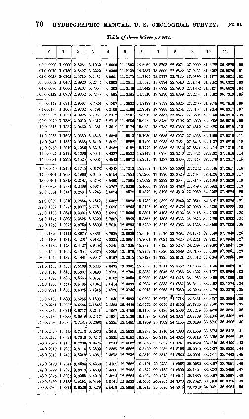
70 HYDROGRAPHIO MANUAL, U. S. GEOLOGICAL SURVEY. (NO. 94.
Table of three-halves powers.
0. 1. 2. 3. 4. 5. 6. 7. 8. 9. 10. 11.
- -------------------------- ------ -.00 0.0000 1.0000 2.8284 5.1962 8.0000 11.1803 14.6969 18.5203 22.6274 27.0000 31.6228 36.4829 .00 .01 0.0010 1.0150 2.8497 5. 2222 8.0300 11.2139 14.7337 18.5600 22.6699 27.0450 31.6702 36.5326 .01
.02 0.0028 1_..0302 2.8710 5.2482 8.0601 11.2475 14.7705 18.5997 22.7123 27.0890 31.7177 36.5824 .02
.03 0.0052 1. 0453 2.8923 5.2743 8.0902 11.2811 14.8073 18.6394 22.7548 27.1351 31.7652 36.6322 .03
.04 0.0080 1. 0606 2. 9137 5.3004 8.1203 11.3148 14.8442 18.6792 22.7973 27.1802 31.8127 36.6820 .04 ,1)5 0.0112 1.0759 2. 9352 5.3266 8.1505 11.3485 14.8810 18.7190 22.8399 27.2253 31.8602 36.7319 .05
- ---------------------------------.or.0147 1.0913 2. 9567 5. 3528 8.1807 11.3822 14.9179 18.7589 22.8825 27.2705 31.9078 36.7818 .06
.070.0185 1.1068 2. 9782 5.3791 8.2109 11.4160 14.9549 18.7988 22.9251 27.3156 31.9554 36.8317 .07
.080.0226 1.1224 2. 9998 5.4054 8.2412 11.4497 14.9919 18.8387 22.9677 27.3608 32.0030 36.8816 .08
.09 0.0270 1.1380 3.0215 5.4317 8.2715 11.4836 15.0289 18.8786 23.0103 27.4060 32.0506 36.9315 .09
.10 0.0316 1.1537 3.0432 5.4581 8.3019 11.5174 15.0659 18.9185 23.0530 27.4512 32.0983 36.9815 .10 - -------------------· ------------ -.11 0.0365 1.1695 3.0650 5.4845 8.3323 11.5513 15.1030 18.9585 23.0957 27.4965 32.1460 37.0315 .11
.12 0.0416 1.1853 3. 0868 5.5110 8.3627 11.5852 15.1400 18.9985 23.1384 27.5418 32.1937 37.0815 .12
.13 0.0469 1.2012 3.1086 5.5375 8. 3932 11.6192 15.1772 19.0386 23.1812 27.5871 32.2414 37.1315 .13
.14 0.0524 1. 2172 3.1306 5.5641 8.4237 11.6532 15.2143 19.0786 23.2240 27.6324 32.2892 37.1816 .14
.15 0.0581 1.2332 3.1525 5.5907 8.4542 11.6872 15.2515 19.1187 23.2668 27.6778 32.3370 37.2317 .15 - ------------------------------- -.16 0.0640 1.2494 3.1745 5.6173 8.4848 11.7213 15.2887 19.1589 23.3096 27.7232 32.3848 37.2817 .16
.17 0.0701 1. 2656 3.1966 5.6440 8.5154 11.7554 15.3260 19.1990 23.3525 27.7686 32.4326 37.3319 .17
.18 0.0764 1.2818 3.2187 5.6708 8.5460 11.7895 15.3632 19.2392 23.3954 27.8140 32.4804 37.3820 .18
.19 0.0828 1. 2981 3. 2409 5.6975 8.5767 11.8236 15.4005 19.2794 23.4383 27.8595 32.5283 37.4322 .19
.20 0.0894 1. 3145 3.2631 5. 7243 8. 6074 11.8578 15.4379 19.3196 23.4812 27-.9050 32.5762 37.4824 .20 - ------------------------------- -.21,0.0962 1.3310 3.2854 5. 7512 8.6382 11.8920 15.4752 19.3599 23.5242 27.9514 32.6241 37.5326 .21
.22 0.1032 1.3475 3.3077 5. 7781 8.6690 11.9263 15.5126 19.~ 23.5672 27.9960 32.6720 37.5828 .22
.23 0.1103 1.3641 3.3301 5.8050 8.6998 ·11. 9606 15.5501 19.4405 23.6102 28.0416 32.7200 37.6331 .23
.2'1.1176 1. 3808 3.3525 5.8320 8. 7307 11.9949 15.5866 19.4808 23.6533 28.0872 32.7680 37.6833 .24
.250.1250 1. 3975 3.3750 5.8590 8. 7616 12.0293 15.6250 19.5212 23.6963 28.1328 32.8160 37.7336 .25 ---
.260.1326 1. 4144 3.3975 5.8861 8. 7925 12.0636 15.6616 19.5576 23.7394 28.1784 32.8640 37.7840 .26
.27 0.1403 1.4312 3.4201 5. 9132 8.8235 12.0981 15.7001 19.6021 23.7825 28.2241 32.9121 37.8343 .27
.28 1).14~2 1.4482 3.4427 5. 9403 8.8545 12.1325 15.7376 19.6425 23.8257 28.2698 32.9600 37.8847 .28
.29 0.1562 1.4652 3.4654 5. 9675 8.8856 12.1670 1_5. 7752 19.6830 23.8689 28.3155 33.0083 37.9351 .29
.30 0.1643 1. 4822 3.4881 5. 9947 8. 9167 12.2015 15.8129 19.7235 23.9121 28.3612 33.0564 37.9855 .30 - -----------------------
28. 40691 33. 1046 --- -
.31 0.1726 1. 4994 3. 5109 6.0220 8. 9478 12.2361 15.8505 19.7641 23.9553 38.0359 .31
.32 0.1810 ]. 5166 3.5337 6.0493 8. 9790 12.2706 15.8882 19.8046 23.9986 28.4527 33.1527 38.0864 .32
.33 0.1896 1. 533~ 3. 5566 6.0767 9.0102 12.3053 15.9260 19.8452 24.0418 28.4985 33.2009 38.1369 .33
.34 0.1983 1.5512 3.5795 6.1041 9.0414 12.3399 15.9637 19.8858 24.0851 28.5444 33.2492 38.1874 .34
.35 0.2071 1.5686 3.6025 6.1315 9.0726 12.3746 16.0015 19.9265 24.1285 23.5902 33.2974 38.2379 .35 - -------------------- -.------------- -.36 0.2160 1. 5860 3.6255 6.1590 9.1040 12.4093 16.0393 19.9672 24.1718 28.6361 33.3457 38.2884 .36
.37 0.2251 1. 6035 3. 6486 6.1865 9.1353 12.4440 16.0772 20.0079 24.2152 28. 6820 33. 3940 38.3390 .37
.38 0.2342 1. 6211 3.6717 6.2141 9.1667 12.4788 16.1150 20.0486 24.2586 28.7279 33.4423 38.3896 .38
.39 0.2436 1. 6388 3. 6949 6.2417 9.1981 12.5136 16.1529 20.0894 24.3021 28.7739 33.4906 38.4402 .39
.40 0.2530 1.6565 3. 7181 6.2693 9.2295 12.5485 16.1909 20.1302 24.3455 28.8199 33.5390 38.4908 .40 - -------- --------------------- -.41 0.2625 1.6743 3. 7413 6.2970 9.2610 12.5833 16.2288 20.1710 24.3890 28.1659 33.5874 38.5415 .41
.42 0.2722 1.6921 3. 7646 6.3247 9.2925 12.6182 16.2668 20.2118 24.4325 28.9119 33.6358 38.5922 .42
.43 0. 2820 1. 7100 3. 7880 6.3525 9.3241 12.6532 16.3048 20.2527 24.4761 28.9579 33.6842 38.6429 .43
.44 0. 2919 1.7280 3. 8114 6.3803 9.3557 12.6882 16.3429 20.2936 24.5196 29.0040 33.7327 38.6936 .44
.45 0.3019 1. 7460 3.8349 6,4081 9. 3873 12.7232 16.3810 20.3345 24.5632 29.0501 33.7811 38.7443 .45 ---
1. 76411 3. 8584 -------------------------- -
. 4610.3120 6.4360 9.4189 12.7582 16.4191 20.3755 24.6068 29.0962 33.8297 38.7951 .46
.. T''" 1. 7823 3. 8819 6. 4639 9.4506 12.7933 16.4572 20.4165 24.6505 29.1424 33.8782 38.8459 .47
.480.3325 1. 80C5 3. 9055 6.4919 9.4824 12.8284 16.4954 20.4575 24.694.1 29.1885 33.9267 38.8967 .48
.490.3430 1. 8188 3. 9292 6.5199 9.5141 12.8635 16.5336 20.4985 24.7378 29.2347 33.9753 38.9475 .49
.50,0.3536 1.8371 3.9529 6.5479 9.5459 12.8986 16.5718 20.5396 24.7815 29.2810 34.0239 38.9984 .50

MURPHY, HOYT, J .AND HOLLISTER. TABLES .
Table of three-halves powers-Continued.
o. 1. 2. 3. 4. 5. 6. 7. 1 8. 9. 10. 11.
- ------
71
• 51 0. 3642 1. 8555 3. 9766 6. 5760 9. 5778 12. 9338 16. 6101 20. 5807 24. 8253 29.3272 34. 0725 39. 0493 . 5
• 52 0. 3750 1. 8740 4. 000-! 6. 6041 9. 6097 12. 9691 16. 6484 20. 6218 24. 8691 29. 3735 34.1211 39.1002 . 52
. 53 0. 3858 1. 8925 4. 0242 6. 6323 9. 6416 13. 0043 16. 6867 20. 6630 24. 9129 29. 4198 34. 1698 39.1511 . 53
. 5410. 3968 1. 9111 4. 0481 6. 6605 9. 6735 13. 0396 1~. 7250 20. 7041 24. 9567 29. 4661 34. 2185 39. 2020 54
-~.:r 4079 1. 9297 4. 2520 6. 6887 9. 705513. 0749 16. 7634 20. 7453 25. 0005 29. 5124 34.2672 39.2530 . 55
• 5610. 4191 1. 9484 4. 0960 6. 7170 9. 737513.1103 16. 8018 20. 7866 25.0444 29. 5588 34.3159 39.3040 . 56
• 5710.4303 1. 9672 4.1200 6. 7453 9. 769513.1457 16.8402 20.8278 25.0883 29.6052 34.3647 39.3550 . 57 • 58 0. 4417 1. 9860 4. 1441 6. 7737 9. 8016 13. 1811 ] 6. 8787 20. 8691 25. 1322 29. 6516 34. 4135 39. 4060 58
. 59:0.4532 2. 0049 4.1682 6. 8021 9. 8337113. 2165 16. 9172 20. 9104 25. 1762 29. 6980 34. 4623 39. 4571 . 59
. 60 0. 4648 2. 0238 4.1924 6. 8305 9. 8659 13. 2520 16. 9557 20. 9518 25. 2202 29 7445 34. 5111 39. 5082 60
~ 0. 4764j 2. 0429 4. 2166 6. 8590 9. R981113. 2875 16.9943 20.9931 25.2642 29.7910 34.5599 39.5593 . 6
• 62 0.488212. 0619 4. 2408 6. 8875 9. 9303113. 32.~1 17. 0328 21. 0345 25. 3082 29. 8375 34. 6088 39. 6104 . 62
. 6310.500012.0810 4. 2651 6. 9161 9. 96261
1'13. 3587 17.0714 21.0759 25.3522 29.8841 34.6577 39.6615 . 63 .6410.5120 2.1002 4.2895 6.9447 9.994913.3943 17.110121.1174 25.3963 29.9306 34.7066 39.7127 64
~0.5240 2.1195 4.3139 6.97331 10.027213.4299 17.1488 21.1589 25.4404 29.9772 34.7557 39.7639 65
• 66 0. 5362 2.1388 4. 3383 7. 0020 10.0596 13.4166 17.1874 21.2004 25.4845 30.0238 34.8045 39.8151 . 66
. 67 0. 5484 2.1581 4. 3628 7. 0307 10.592013.5013 17.2172 21.2419 25.5287 30.0704 34.8535 39.8663 . 67
.680.5607 2.1775 4.3874 7.0595 10.124413.5370 17.2649 21.2834 25.5729 30.1171 34.9025 39.9176 .68
• 69 0. 5732 2. 1970 4. 4119 7. 0883 10. 1569 13. 5728 17. 3037 21. 3250 25. 6171 30. 1638 34. 9516 39 9689 . 69
. 7010.5857 2. 2165 4. 4366 7.1171 10.189413.6086 17.3425 21.3666 25.6613 30.2105 35.0006 40.0202 . 70
~!0.5983 2.2361 4.4612 7.1460 10.221413.6444 17.3814 21.4083 25.7056 30.2572 35.0497 40.0715 .7
.7210.6109 2.2558 4.4859 7.1749 10.254513.6803 17.4202 21.4499 25.7499 30.3040 35.0988 40.1228 .72
.730.6237 2.2755 4.5107 7.203810.287113.7161 17.459121 .. 4916 25.7942 30.3507 35.1479 40.1742 .73
. 741o. 6366 2. 2952 4. 5355 7. 2328 10.319713.7521 17.4981 21.5333 25.8395 30.3975 35.1971 40.2256 . 74
. 7510.6495 2. 3150 4. 5604 7. 2618 10.352413.7880 17.5370 21.5751 25.8828 30.4444 35.2462 40.2770 . 75
~110. 6626 2. 3349 4. 5853 7. 2909 10.385113.8240 17.5760 21.6169 25.9272 30.4912 35.2954 40.3284 . 76 • 77 0. 6757 2. 3548 4. 6102 7. 3200 10. 4178 13. 8600 17. 6150 21. 6587 25. 9716 30. 5381 35. 3446 . 40. 3798 . 77
. 78 0. 6889 2. 3748 . 6352 7. 3492 10.450613.8961 17.6541 21.7005 26.0161 30.5850 35.3939 40.4313 . 78
. 79 0. 7Q22 2. 3949 4. 6602 7. 3783 10.483413.9321 17 .. 6931 21.7423 26.0605 30.6319 35.4431 40.4828 . 79
.800.7155 2.4150 4.6853 7.4076 10.516313.9682 17.7322 21.7842 26.1050 30.6789 35.4924 40.5343 80
.81·0.7290 2.4351 4."7104 7.436810.549214.0044 17.7i14 21.8261 26.1495 30.7258 35.5417 40.5859 .8
. 8210.7425 2. 4553 4. 7356 7. 4661110.5812 14.0406 17.8105 21.8681 26.1941 30.7728 35.5911 40.6374 . 82
.830.7562 2.4756 4.7608 7.495510.615014.0768 17.8507 21.9100 26.2386 30.8198 35.6404 40.6890.83
. 8410.7699 2.4959 4. 7861 7. 5248 10.648014.1130 17.8889 21.9520 26.2832 30.8669 35.6898 40.7406 84
. 85(. 7837 2. 516314.8114 7. 55421 10.681014.1493 . 17.9282 21.9940 26.3278 30.9139 35.7392 40.7922 85
~0.7975 2.5367 4.8367 7.5837110.714114.1856 17.9674 22.0361 26.3725 30.9610 35.7886 40.8439 .86 . 8710.8115 2. 5572 4. 8621 7. 6132 10.747214.2219 18.0067 22.0781 26.4171 31.0081 35.8380 40.8955 . 87
. s8;o. 8255 2. 5777 4. 8875 7. 6427, 10.780314.2582 18.0461 22.1~02 26.4618 31.0553 35.8875 40.9472 . 88
. 89 0. 8396 2. 5983 4. 9130 7. 6723 10.813414. 29-!6 18.0854 22.1623 26.5065 31.1024 35.9370 40.9989 . 89
~1 0. 8538 2. 6190 4. 9385 7. 7019110.846614.3311 18.1248 22.2045 26.5523 31.1496 35.9865 41.0507 90
. 910.8681 2. 6397 4. 9641 7. 7315 10.879814.3675 18.1642 22.2467 26.5960 31.1968 36.0360 41.1024 .. 9
. 92 0. 8824 2. 6604 4. 9897 7. 7702 10. 913114~4040 18.2037 22.2889 26.6408 31.2441 36.0856 41.1542 . 92
. 93 0. 8969 2. 6812 5. 0154 7. 7909 10.946414.4405 18.2432 22.3311 26.6856 31.2913 36.1352 41.2060 . 93
. 9410.9114 2. 7021 5. 0411 7. 8207 10.979714. 4770 18.2827 22.3733 26.7305 31.3386 36.1848 41.2578 94
. 95 0. 9259 2. 7230 5. 0668 7. 8505 11.013114.5136 18.3222 22.4156 26.7753 31.3850 36.2344 41.3097 . 95
. 96 0. 9406 2. 7440 5. 0926 7. 8803 11.046414.5502 18.3617 22.4.579 26. 820'2 31.4332 36.2841 41.3615 96
. 97 0. 9553 2. 7650 5.1184 7. 9102 11.079914.5869 18.4013 22.5003 26.8651 31.4806 36.3337 41.4134 . 97
. 98 0. 9702 2. 7861 5.1443 7. 9401 11.1133 14. 6235 18. 4409 22. 5426 26. 9100 31. 5280 36. 3834 41. 4653 98
~ 0. 9850 2. 8072 5. 1702 7. 9700 11. 1468 14. 6602 18. 4806 22. 5850 26. 9550 31. 5754 36.4331 41. 517311 • 99
1.0011.0000 2.8284 5.1962 8.0000 11.180314.6969 18.5203 22.627! 27.0000 31.6228 36.4829 41.56921.00

72 HYDROGRAPHIC MANUAL, U. S. GEOLOGICAL SURVEY.
CONVENIENT EQUIVALENTS.
1 second-foot equals 50 California miner's inches. 1 second-foot equals 38.4 Colorado miner's inches. 1 second-foot >tquals 40 Arizona miner's inches. 1 second-foot equals 7.48 United States gallons per second. 1 second-foot equals 6.23 British imperial gallons. 1 second-foot for one day equals 1.9835 acre-feet. 1 second-foot for one day equals 646,272 United States gallons. 1 second-foot for one year equals 0.000214 cubic mile. 1 second-foot for one year covers 1 square mile 1.131 feet deep. 1 second-foot equals 449.9 gallons per minute. 1 second-foot equals about one acre-inch per hoU:r. 1 cubic foot of water weighs 62.47 pounds. 100 California miner's inch equals 2 second-feet. 100 California miner's inches equals 15 United States gallons per second. 100 California miner's inches equals 77 Colorado miner's inches. 100 California miner's inches for one day equals 4 acre-feet. 100 Colorado miner's inches equals 2.60 square feet. 100 Colorado miner's inches equals 19.5 United States gallons per second. 100 Colorado miner's inches equals 130 California miner's inches. 100 Colorado miner's inches for one day equals 5.2 acre-feet. 100 United States gallons per minute equals .223 second-foot. 100 United States gallons per minute for one day equals 44 acre-feet. 1 million United States gallons per day equals 1.55 second-feet. 1 million United States gallons equals 3.07 acre-feet. I million cubic feet equals 22.95 acre-feet. 1 acre-foot equals 325,850 gallons. A layer 1 inch deep on one square mile equals 2,323,200 cubic feet. A flow of 1 second-foot in one year equals 31,536,000 cubic feet. 1 inch deep on 1 square mile equals 0.0737 second-foot per year; 10 inches deep on 1 square mile equals 0. 7367 second-foot per year. A flow of 1 second-foot per year covers 1 square inch 13.589. 1 cubic mile equals 147,198,000,000 cubic feet. 1 cubic mile equals 4,667 second-feet. 1 second-foot per year equals 31,536,000 cubic feet. 1 second-foot per year equals 0.000214 cubic mile. 1 foot per second equals 1.077 kilometers per hour. 1 foot per second equals 0.68 mile per hour. 1 inch equals 2.54 centimeters. 1 foot equals 0.3048 meter. 1 yard equals 0. 9144 meters. · 1 mile equals 1.60935 kilometers. 1 square yard equals 0.836 square meter. 1 acre equals 0.4047 hectare. 1 square mile equals 259 hectares. 1 square mile equals 2.59 square kilometers. 1 cubic foot equals 0.0283 cubic meter. 1 cubic yard equals 0. 7646 cubic meter. 1 gallon equals 3. 7854 liters. 1 pound equals 0.4536 kilogram.
[NO. 94.
1 atmosphere equals about 15 pounds per square inch, 1 ton per square foot, 1 kilo per square centimeter.
Acceleration of gravity equals 32.16.feet per second every second.

MURPHY, HOYT, '] AND HOLLISTER. TABLES.
1 acre equals 209 feet square, nearly. 1 ~ere equals 43,560 square feet, equals 4,840 square yards. 1 mile equals 1, 760 yards, equals 5,280 feet, equals 63,360 inches. 1 cubic foot equals 7.48 gallons, equals 0.80-1 bushel. 1 gallon equals 8.34 pounds of water. 1.gallon equals 231 cubic inches (liquid measure). 1 avoirdupois pound equals 7,000 grains. 1 troy pound equals 5, 760 grams. 1 meter equals 39.37 inches. Log. 1.5951654. 1 meter equals 3.28083 feet. Log. 0.5159842. 1 meter equals 1.093611 yards. Log. 0.0388629. 1 meter equals 0.00062137 mile. I~og. 6. 7933495. 1 kilometer equals 3,281 feet, equals~ mile, nearly. 1 square meter equals 10,764 square feet, equals 1.196 square yard. 1 hectare equals 2.4 71 acres. 1 cubic meter equals 35.314 cubic feet, equals 1.308 cubic yards. 1liter equals 1.0567 quarts. 1 gram equals 15.43 grains. 1 kilogram equals 2.2046 pounds. 1 tonneau equals 2,204.6 pounds. 1 cubic meter per minute equals 0.5886 second-foot. 1 horsepower equals 550 foot-pounds per second. 1 horsepower equals 76 kilogrameters per second. 1 horsepower equals 746 watts. , 1 horsepower equals 1 second-foot of water falling 8.8 feet. 1 second-foot falling 10 feet equals 1.135 horsepower. 1-! horsepowers equals about 1 kilowatt.
73
· . Sec.-ft. x fall in feet. To calculate water power qmckly: 11 Net horsepower on
water wheel, realizing 80 per cent of the theoretical power. Quick formula for computing discharges over weirs: Cubic feet per minute equals
0.4025 lv-fi3; l=length of weir in inches; h=head in inches flowing over weir,
measured from surface of still water. To change miles to inches on map:
Scale 1 :125000, 1 mile= 0.50688 inches. Log. = 9. 7049052. Scale 1:90000, 1 mile=0.70400 inches. Log. =9.8475727. Scale 1 : 62500, 1 mile= 1. 01376 inches. Log. = 0. 0059352. Scale 1:45000, 1 mile= 1.40800 inches. Log. =0.1486027.


INDEX.
Page. Acre-feet, conversion of, into millions of
gallons, table for ...... ----- .. __ 65 conversion of, into second-feet per day,
table for. ____ ----- ____ ..... ____ . 64
conversion of second-feet into, tables for .. ____ ... ---------_---· ....... 54-56
equivalents of ..... ---_-·- ___ ----- ___ ... 72 Authority for work, instructions concern-
ing............................. 39 Bench marks, location of .. .. .. .... .. .. .. .. 17 Boat stations, description and illustrations
of. ........................... 12,13-14 Bridge stations, measurements made from. 12 Cable station, car, gage, etc., plate and fig-
ure showing_. __ .. _ .. __ ......... 12 Cable stations, equipment of ........ _ ...... 12-13 Chain gage, U. S. G. S. standard, descrip-
tion of. ........................ _ 15-17 figure showing ..... _ .................. _ 16
Computation forms, list of.................. 33 Cubic feet, equivalents of .. .. .... .. .. .. .. . • 72 Cubic miles, equivalents of._ ........ _...... 72 Current meter, battery and buzzer of...... 30
description of, and suggestions concern-ing use of. ..... _.. .. . .. .. .. .. .. 26-30
measurements by, computation of····- 46-49 rerating of ........ !..................... 31 stay lines on, use of..................... 17
figures showing .. _ .... _ .. _.. .. .. .. . 13, 15 Current-nieter gaging stations, classification
and equipment of .............. 11-14 favorable conditions for ... _ ............ 10-11 unfavorable conditions for ...... _ .. _... 12
Current-meter notebooks, instructions for use of. ........ __ ................ 34-35
Current-meter rating station at Denver, Colo., view of................... 20
Decimal figures, rule for reducing number of............................... 46
Denver, Colo., current-meter rating station at, view of. _ ..... ____ .. . . . . . . . . . 20
Depth, computation of, formulas for....... 47 measuremen.ts of, methods of ........ 18-19,21
Discharge, computation of, formulas for.. 47 computation of, instructions for ........ 42-44
factors for computation of ..... _..... 18 report of gage height and, Rample of... 45
Discharge-measurement cards, instructions for use of .................... ~-- 35
Discharge-measurement forms, list of...... 33 Discharge measurements, checking of. .. .. 22
classes of .. _ .. _ .. _.... .. .. . .. .. .. . .. .. .. 22-24 distribution of. ___ ...................... 23 object of making .................. _.... 41
Page. District engineer, duties of................. 31 District hydrographer, duties of . . . . . . . . . . . 31 Engineers (district), duties of.............. 31 Equivalents, table of .... _ ....... _ .......... 72-73 Feet, conversion of, to meters, table for.... 67 Feet per second, conversion of, into miles
· per hour, table for ............. 62 See also Second-feet.
Fellows, A. L., acknowledgment to . . . . . . . . 10 Field, John E., acknowledgment to........ 10 Field notes, computation of, time for . . . . . . 32 Flood-flow measurements, instructions for. 23 Floods, reports on . . . . . . . . . . . . . . . . . . . . . . . . . . 25 Forms, standard, i•structions for use of .... 34-40
list of................................... 33 use of, for transmitting data............ 32
Gage-height books, instructions for use of.. 34 Gage-height cards, instructions for use of.. 34 Gage-height forms, list of . . . . . . . . . . . . . . . . . . 33 Gage height and discharge report, sample of. 45 Gage heights, object of taking ........... _. 41 Gages, forms of ............................. 14-17
readings of . . . . . . . . . . . . . . . . . . . . . . . . . . . . . 24-25 Gaging stations, ·bench marks at........... 17
classification and equipment of ........ 11-14 cross sections of streams at............. 25 location of, favorable conditions for, .. 10-11
unfavorable conditions for......... 11 purposes of ................... ·... .. .. . .. 10 report on measurement at, sample of . . 48
Gallons, conversion of cubic feet into, table for.............................. 61
conversion of, into cubic feet, table for. 61 conversion of second-feet per day into
millions of, table for . . . . . . . . . . . 63 equivalents of.......................... 72 millions of, conversion of, into acre-
feet, table for .. .. .. .. .. .. .. .. .. 65 Gallons per minute. See Minute-gallons. "Grains perU. S. gallon," conversion of, to
'' parts per million," table for . . 67 Gravity, acceleration of, equivalent of, in
second-feet..................... 72 Grover, N. C., acknowledgment to......... 10 Hall, B. M., acknowledgment to........... 10 Hall, M. R., acknowledgment to........... 10 Hanna, F. W., acknowledgment to........ 10 Hinderlider, M. C., acknowledgment to . . . 10 Horsepower, equivalents of ...... _......... 73 Horsepower of turbines, table for calcula-
tion of.. ........................ 69--70 Horton, R. E., acknowledgment to........ 10 Hydrographer's (resident) monthly report,
sample form for .. .. .. . . .. .. .. .. 37-39
75

76 INDEX.
Page. Hydrographers (district), duties of . . . .. . .. 31 Hydrographic reports, miscellaneous, in-
formation concerning.......... 41 Information concerning work in progress,
requests made for, instructions concerning.... . . . . . . . . . . . . . . . . . 39
Instruments, description and care of. ...... 26-31 Integration method of measuring velocity,
description of . . . . . . . . . . . . . . . . . . 20 Maps, use of, in reports.................... 36 Measurement, units of . . . . . . . . . . .. . . .. . .. . . 46 Meter, current. See Current meter. Meters, conversion of, to feet, table for . . . . 67 Metric measurements, equivalents of ...... 72-73 Miles on map, conversion of, to inches..... 73 Miles per hour, conversion of, into feet per
second, table for. . . . . . . . . . . . . . . . 62 Miner's inch, equivalents of . . . . . . . . . . . . . . . 72 Minimum-flow measurements, importance
of............................... 22 reports on . . . . . . . . . . . . . . . . . . . . . . . . . . . . . . 22
Minute-gallons, conversion of, into second-feet, table for ... _............... 66
Monthly means, computation of ........... 42-44 Multiple-point methods of _measuring veloc-
ity, description of ........... _ .. 20-21 Newell, F. H., letter of transmittal by...... 7 Noble, T. A., acknowledgmentto.......... 10 Notebooks, indexing of ................. _ .. 35-36 Plans for work. approval of ... _.. . . . . . . . . . . 39 Price electric current meter, battery and
buzzer of . _ . . . . . . . . . . . . . . . . . . . . . 30 cross section of, figure showing . . . . . . . . 27 description, and suggestions concern-
ing use of. . . . . . . . . . . . . . . . . . . . . . . 26-30 figures showing . _ ................. ___ .. 26, 28 rerating of.............................. 31 weight vane of, figure showing . . . . . . . . 28 Bee also Current meter .. __ ............. .
Publications containing progress reports on stream measurements, list of... 40
Rating curves, figures showing ........... _. 42, 43 preparation of ........... _ . . . . . . . . . . . . . . 41-42
Rating table, sample of. __ .... _............. 44 Reconnaissancework,featurestobenotedin. 26
reports on, instructions for._ ... _ .... _.. 39 Records, duplication of..................... 32
checking of ..... _ .................. _.... 32 care in keeping of, necessity for.. . . . . . . 31 transmission of, to Washington office.. 32 use of standard forms for .. _.... . . . . . . . . 32
Records, regulations in regard to ... _ ... __ .. 31-41 Redundant figures, rules for rejection of... 46 Report forms, list of ............... _ ..... _.. 33 Report maps, preparation of .... _ .......... 36-37 Reports, miscellaneous hydrographic, in-
formation relating to. . . . . . .. _ . 41 Reports, monthly, forms for ............. 37,38,39
monthly, scope of ............. __ ....... 36,37 Reports of stream measurements, list of
publications containing ....... _._...... 40 Reports on reconnaissance, surveys, etc.,
instructions for .... _ .... :. . . . . . . 39 Reports, special, scope of. . . . . . . . . . . . . . . . . . . 36 Resident hydrographer's monthly report,
sample form for .... _ ........ _ .. 37-39
Page. River stations, form for description of,
instructions for use of . . . . . . . . . . 35 new, reports on. . . . . . . . . . . . . . . . . . . . . . . . . 39
Run-off, computation of. ................ _ .. 42-44 computation of, tables for .............. 52-53 conversion of, from second-feet per
square mile into depth in inches per month, tables for ........... 58-60
depth of, computation of, instructions for.............................. 57
Salina, Kans., cross section of Saline River near, figure showing . . . . . . . . . . . 47
Saline River, cross section of, near Salina, Kans., figure showing.... . . . . . . 47
Second-feet, conversion of, into acre-feet, tables for............. . . . . . . . . . . 54-56
conversion of, into minute-gallons, table for........................ 66
equivalentsof.......................... 72 Second-feet per day, conversion of, into
acre-feet, table for.............. 64 conversion of, into millions of gallons,
table for........................ 63 Second-feet per square mile, conversion of
run-off in, into depth in inches per month, tables for ........... 58-60
Single-point method of measuring velocity, description of ....... , . . . . . . . . . . 19-20
Sketches, use of, in reports.. . . . . . . . . . . . . . . . 36 Soundings, directions for making .......... 18-19
initial point for, marking of............ 19 Standard forms, instructions for use of . . . . 34-40
list of................................... 33 use of, for transmitting data ........ :. . 32
Station-rating curves, figures showing ..... 42-43 Stay line, method of attachment of, by use
of pole, figure showing . . . . . . . . . 15 method of manipulation of, figure show-
ing . . . . . . . . . . . . . . . . . . . . . . . . . . . . . 13 Stay lines, use of, description of............ 17 Stout, 0. V. P., acknowledgment to....... 10 Stream measurements, publications con-
taining progress reports on, list of............................... 40
Swendsen, G. L., acknowledgment to...... 10 Tables, miscellaneous ...................... 61-71 Three-halves powers, tables of ....... 69-70,70-71 Timber gage, description of. ............... 14-15 Turbines, horsepower of, table for calcula-
tion of ....... _ .................. 69-70 Units of measurement...................... 46
0
Velocity, computation of, formula for...... 47 measurements of, methods for ... _ ...... 19-21
Vertical-velocity curve, computation of ... 49-51 figure showing ...... _ .................. _ 51 sample of, figure showing.............. 51
Vertical-velocity-curve method of measur-ing velocity, description of..... 21
Vertical-velocity measurement, report of, sample of....................... 50
Vouchers and miscellaneous forms, list of. 33 Wading, method of measuring discharge by. 21 Water power, calculation of, formulas for.. 73 Weir calculation, formulas for............. 73 Winter discharge measurements, impor-
tance of . . . . . . . . . . . . . . . . . . . . . . . . 24

LIBRARY CATALOGUE SLIPS.
[Mount each slip upon a separate card, placing the subject at the top of the second slip. The name of the series should not be repeated on the serie1:1 card, but the additional numbers should be added, as received, to the firt entry.]
Murphy, Edward C[harles] . . . . Hydrographic manual of the United States Geo
~ ~ logical survey, prepared by Edward C. Murphy, John C. -<~~ Hoyt, and George B. Hollister. Washington, Gov't
print off., 1904.
76 p., 11. illus., 2 pl. 23~cm. (U. S. Geological survey. Water-supply and irrigation paper no. 94.)
Subject series M, General hydrographic investigations, 9.
Murphy, Edward C[harles]. ~ ... Hydrographic manual of the United States Geo~ logical survey, prepared by Edward C. Murphy, Jqhn C. 00
Hoyt, and George B. Hollister. Washington, Gov't print. off., 1904.
76 p., 1 1. illus., 2 pl. 23~cm. (U . .J. Geological survey. Water-supply and irrigation paper no. 94.)
Subject series M, General hydrographic investigations, 9.
U. S. Geological survey. Water-supply and irrigation papers.
94· Murphy, E. C. Hydrographic manual of the U. S. Geological survey, by E. C. Murphy, J. C. Hoyt, and G. B. Hollister. 1904.
l.T. S. Dept. of the Interior. see also
U. S. Geological survey.


SERIES K-PUMPING WATEF.
WS 1. Pumping water for irrigation, by H. M. Wilson. 1896. 57 pp., 9 pls. WS 8. Windmills for irrigation, by E. C. :!lfurphy. 1897. 49 pp., 8 pis. WS 14. New tests of certain pumps and water lifts used in irrigation, by 0. P. IIood. 1898. 91 pp.,
1 pl. WS 20. Experiments with windmills, by T. 0. Perry. 1899. 97 pp., 12 pls. WS 29. Wells and windmills in Nebraska, by E. H. Barbour. 1899. 85 pp., 27 pis. WS 41. The windmill; its efficiency and economic usc, Pt. I, by E. C. Murphy. 1901. 72 pp., 14 plR. WS 42. The windmill, Pt. II (continuation of No. 41). 1901. 73-147 pp., 15-16 pls. WS 91. Natural features and economic development of the Sandusky, ;'.I>tumec, l\Iuskingum, and
Miami drainage areas in Ohio, by B. H. Flynn and M. S. Flynn. 1904. 130 pp.
SER!ES ~QUALITY OF WATER.
WS 3. Sewage irrigation, by G. W. Rafter. 1897. 100 pp., 1 pls. WS 22. Sewage irrigation, Pt. II, by G. W. Rafter. 1899. 100 pp., 7 pis. WS 72. Sewage pollution in the metropolitan area near New York City and its effects on inland water
resources, by l\I. 0. Leighton. 1902. 75 pp., 8 pls. WS 76. Observations on flow of rivers in the vicinity of New York City, by H. A. Pressey. 1903.
08 pp., 13 pis. ·WS 79. Normal and polluted water in northeastern United States, by l\I. 0. Leighton. 1903. 192 pp.
SERIES M-GENERAL HYDROGRAPHIC lNYESTIGATIONS.
WS 56. l\Icthods of stream measurement. 1901. 51 pp., 12 pls. WS 64. Accuracy of stream measurements, by E. C. Murphy. 1902. 99 pp., 4 pls. WS 76. Observations on the flow of rivers in the vicinity of New York City, by H. A. Pressey. 1903.
108 pp., 13 pis. WS 80. The relation of rainfall to run-off, by G. W. Rafter. 190& 104 pp. WS 81. California hydrography, by G. B. Lippincott. 1903. 488 pp., 1 pl. WS 88. The Passaic flood of 1902, by G. B. Hollister and M. 0. Leighton. 1903. 56 pp., 15 pi,. WS 91. Matural features and economic development of the Sandusky, Maumee, Muskingum, and
Miami drainage areas in Ohio, by B. H. Flynn and M.S. Flynn. 1904. 130 pp. WS 92. The Passaic flood of 1903, by M. 0. Leighton. 1904. 18 pp., 7 pls. WS 94. Hydrographic Manual of United States Geological Survey, by E. C. Murphy, J. C. Hoyt, and
G. B. Hollister. 1904. - pp., 2 pis.
SERIES N-W ATER POWER.
WS 24. Water resources of State of New York, Pt. I, by G. W. Rafter. 1899. 92 pp., 13 pls. ws· 25. Water resources of State of New York, Pt. II, by G. W. Rafter. 1899. 100-200 pp., 12 pis. WS 14. Profiles of ri,vers, by Henry Gannett. 1901. 100 pp., 11 pls. WS 62. Hydrography of the southern Appalachian l\fountain region, Pt. I, by H. A. Pressey. 1902.
95 pp., 25 pis. WS 63. Hydrography of the Southern Appalachian Mountain region, Pt. II, by H. A. Pressey. 1902.
96-190 pp., 26-44 pls. WS 69. Water powers of the State of Maine, by U. A. Pressey. 1902. 124 pp., 14 pls,
IRR 94-3

SERIES 0-tJNDERGROCND W A.TERS.
WS 4. A reconnaissance in southeastern Washington, by I. C. Russell. 1897. 96 pp., 7 pis. WS 6. Underground waters of southwestern Kansas, by Erasmus Haworth. 1897. 65 pp., 12 pis. WS 7. Seepage waters of northern Utah, by Samuel Fortier. 1897. 50 pp., 3 pls. WS 12. Underground waters of southeastern Nebraskn., by N.H. Darton. 1898. 56 pp., ~1 pis. WS 21. Wells of northern Indiana, by Frank Leverett. 1899. 82 pp., 2 pls. WS 26. Wells of southern Indiana (continuation of No. 21), by Frank Leverett. 1899. 64 pp. WS 30. Water resources of the Lower Peninsula of l\Iichigan, by A. C. Lane. 1899. 97 pp., 7 pis. WS 31. Lower Michigan mineral waters, by A. C. Lane. 1899. 97 pp., 4 pls. WS 34. Geology and water resources of a portion of southeastern South Dakota, by J. E. Todd. 1900.
34 pp., 19 pls. WS 53. Geology and water resources of Nez Perces County, Idaho, Pt. I, by I. C. Russell. 1901. 86
pp., 10 pls. WS 54. Geology and water resources of Nez Perces County, Idaho, Pt. II, by I. C. Russell. 1901.
87-141 pp. WS 55. Geology and water resources of a portion of Yakima County, Wash., by G. 0. Smith. 1901. 68
pp., 7 pls. WS 57. Preliminary list of deep borings in the United States, Pt. I, by N. H. Darton. 1902. 60 pp. WS 59. Development and application of water in southern Californi&, Pt. I, by J. B. Lippincott. 1902.
95 pp., 11 pls. WS 60. Development and application of water in southern California, Pt. II, by J. B. Lippincott. 1902.
96-140 pp. WS 61. Preliminary list of deep borings in the United States, Pt. II, by N. H. Darton. 1902. 67 pp. WS 67. The motions of underground waters, by C. S. Slichter. 1902. 106 pp., 8 pis. B 1§9. Geology and water resources of the Sno.kc River Plains of Idaho, by I. C. Russell. 1902. 192
pp., 25 pls. WS 77. Water resources of Molokai, Hawaiian Islands, by Waldemar Lindgren. 1903. 62 pp., 4 pis. 'fS 78. Preliminary report on artesian basins in southwestern Idaho and southeastern Oregon, by
I. C. Russell. 1903. 53 pp., 2 pls. PP 17. Preliminary report on the geology and water resources of Nebraska west of the ·one hnndred
and third meridian, by N.H. Darton. 1903. 69 pp., 43 pis. WS 90. Geology and water resources of part of the lower .Tames River Valley, South Dakota, by J. E.
Todd and C. M. Hall. 1904. 47 pp., 23 pis. The following papers also relate to this subject: Underground waters of Arkansas Valley in eastern
Colorado, by G. K. Gilbert, in Seventeenth Annual, Pt. II; Preliminary report on artesian waters of a portion of the Dakotas, by N. H. Darton, in Seventeenth Annual, Pt. II; Water resources of Illi·· nois, by Frank Leverett, in Seventeenth Annual, Pt. II; Water resources of Indiana and Ohio, by Frank Leverett, in Eighteenth Annual, Pt. IV; New developments in well boring and irrigation in eastern South Dakota, by N.H. Darton, in Eig-hteenth Annual, Pt. IV; Rock waters of Ohio, by Edward Orton, in Nineteenth Annual, Pt. IV; Artesian well prospects in the Atlantic Coastal Plain region, by N.H. Darton, Bulletin No. 138.
SERIES P-HYDltOGRA.PHIC PROGRESS l{EPORTS,
Progress reports may be found in the following publications: For 1888-89, Tenth Annual, Pt. ll; for 1889-90, .Eleventh Annnal, Pt. II; for 1890-91, 'l'welfth Annual, Pt. II; for 1891-W, Thirteenth Annual, Pt. III; for 1893-94, B 131; for 1895, B 140; for 1896, Eighteenth Anmml, Pt. IV, WS 11; for 189i, Nineteenth Annual, Pt. IV, WS 15, 16; for 1898, Twentieth Annual, Pt. IV, WS 27, 28; for 1899, Twenty-first Annual, Pt. IV, WS 36-39; for 1900, Twenty-second Annunl, Pt. IV, WS 47-52; for 1901, WS 65, 66, 75; for 190'2, WS 82-8[>.
Correspondence should be addressed to
IRR 94-4
THE DIRECTOR,
UNITED STATES GEOLOGICAL SURVEY,
\VASHINGTON, D. c.