
Hydrogen from Exhaust Gas Fuel Reforming: Greener, · PDF filefrom Exhaust Gas Fuel Reforming:...
49
1 Future Power Systems Group “The future begins in the past” Hydrogen from Exhaust Gas Fuel Reforming: Greener, Leaner and Smoother Engines Miroslaw L. Wyszynski Thanos Megaritis Roy S. Lehrle Future Power Systems Group The University of Birmingham
Transcript of Hydrogen from Exhaust Gas Fuel Reforming: Greener, · PDF filefrom Exhaust Gas Fuel Reforming:...

1
Future Power Systems Group
“The future begins in the past”
Hydrogenfrom Exhaust Gas Fuel Reforming:
Greener, Leaner and SmootherEngines
Miroslaw L. WyszynskiThanos Megaritis
Roy S. Lehrle
Future Power Systems GroupThe University of Birmingham
2
Future Power Systems Group
“The future begins in the past”
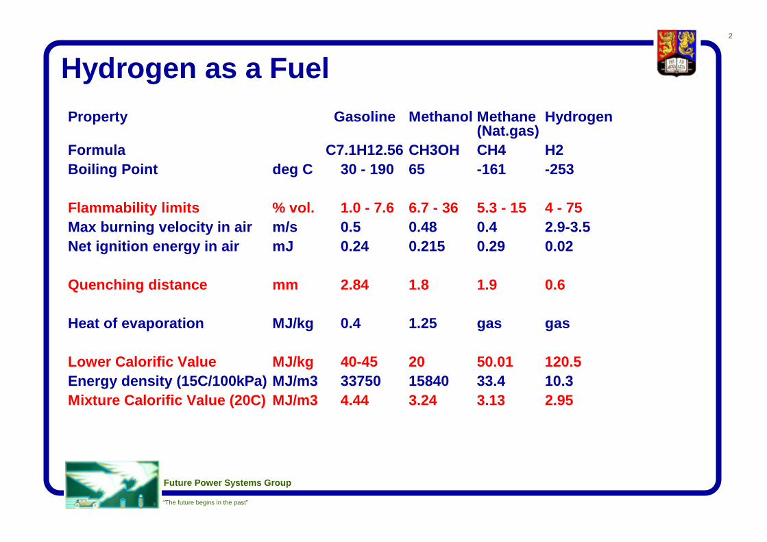
Hydrogen as a FuelProperty Gasoline Methanol Methane Hydrogen
(Nat.gas)Formula C7.1H12.56 CH3OH CH4 H2Boiling Point deg C 30 - 190 65 -161 -253
Flammability limits % vol. 1.0 - 7.6 6.7 - 36 5.3 - 15 4 - 75Max burning velocity in air m/s 0.5 0.48 0.4 2.9-3.5Net ignition energy in air mJ 0.24 0.215 0.29 0.02
Quenching distance mm 2.84 1.8 1.9 0.6
Heat of evaporation MJ/kg 0.4 1.25 gas gas
Lower Calorific Value MJ/kg 40-45 20 50.01 120.5Energy density (15C/100kPa) MJ/m3 33750 15840 33.4 10.3Mixture Calorific Value (20C) MJ/m3 4.44 3.24 3.13 2.95

3
Future Power Systems Group
“The future begins in the past”
Use of Hydrogen in IC Engines
• As a pure fuel– Long term strategy
• As an additive to fossil fuels– Lean/Diluted Burn– Exhaust Gas Recirculation
• Problems:– Production Thermoeconomics– Storage on board
• Solution: Production on-board

4
Future Power Systems Group
“The future begins in the past”
Off-board produced hydrogen
• Remote energy & CO2 cost• Lack of distribution infrastructure• Storage problems for use on board
– hydrides:weight & range penalty
– compressed H2:bulk
– liquid H2 - best,high energy cost for liquefaction

5
Future Power Systems Group
“The future begins in the past”
Fuel storage requirements
0 50 100 150 200 250 300 350 400
Gasoline
Diesel fuel
Rapeseed oil methylester
Autogas
Ethanol
Methanol
CNG (165 bar)
Liquid H2 Cryogen tank
Storage requirements for fuels equivalent to 55 litres gasoline
Space reqd. (litre)
Mass (kg)
Source: Volkswagen Documentation "Alternative Fuels"
350124
263308
88121
76103
83105
6467
4660
4667

6
Future Power Systems Group
“The future begins in the past”
On-board Production of Hydrogen:Fuel Reforming• Production of hydrogen on-board from hydrocarbons or alcohol• Three main reaction paths
– steam reforming e.g. CH4 + H2O = CO + 3H2
– direct partial oxidation 2CH4 + O2 = 2CO + 2H2
– thermal decomposition CH3OH = CO + 2H2
• Exhaust gas reforming– direct contact between exhaust gases and HC fuel over catalyst– combination of all three fundamental processes, e.g.
CH4 + 0.33(CO2 + 2H2O + 7.52N2) = 1.33(CO + 2H2 + 1.88N2)∆RH = 220 kJ/kmol (endothermic)
combustion of reformed fuel:(CO + 2H2 + 1.88N2) + 1.5(O2 + 3.76N2) = CO2 + 2H2O + 7.52N2

7
Future Power Systems Group
“The future begins in the past”
Engine-Reformer System
Exhaust
EngineFuel Reformer
HotExhaust
Gas
Reformate
Air/Fuel
Power
HC/CO/NOxRemoval
Fuel

8
Future Power Systems Group
“The future begins in the past”
Parameters affecting the Quality andQuantity of Reformed Fuel
Quality and Quantity of Reformed fuel
Engine operation - transient -stationary Operation time
- engine warm up
Surplus Energy in the Exhaust
Exhaust Mass Flowrate
Reactor designCatalyst
Location of Reactor
Exhaust composition
Engine design -lean burn -EGR -turbocharger -supercharger
Supplied fuel
Fuel, Air, Water input into Reforming Reactor

9
Future Power Systems Group
“The future begins in the past”
Main modes of fuel reforming withexhaust gas• High exhaust temperature (>800-900 degC)
– High hydrogen yield (over 30% in reformed gas)– Energy recovery from exhaust gas to increase CV of fuel– All or most fuel could be reformed– Possible at high engine load
• Lower temperature (500-700 degC)– Up to 20% hydrogen obtainable– Temperature may be boosted by partial oxidation– Mainly for hydrogen enrichment of EGR to improve combustion– Possible at part load, maybe at idle

10
Future Power Systems Group
“The future begins in the past”
Hydrogen enrichment
• Increases flame speedGasoline Methane Hydrogen
burning velocity in air (m/s) 0.5 0.4 2.9-3.5
• Reduces emissions of hydrocarbons
Quenching distance (mm) 2.84 1.9 0.6
• Allows higher levels of EGR (thus reduced NOx)with good combustion stability

11
Future Power Systems Group
“The future begins in the past”
Exhaust Reforming of Liquid Fuels(n-Heptane and Gasoline)
University of Birmingham:ML Wyszynski, MR Jones, H West, R Chen, Y Jamal, T Wagner (MechanicalEngineering)RS Lehrle, J Riches, D Sarson (School of Chemistry)
D Bradley, CGW Sheppard (University of Leeds)B Parsons, D Szczupak, R Lee (Jaguar Cars)S Wallace, D Richardson, S Shillington, M Davies (Rover Group)Drs P Hawker & RJ Brisley, Dr J Frost (Johnson Matthey)M Shaw (Inco Alloys International)Dr R Mortier, Mr S Orszulik (Castrol Ltd)
SERC - MPVI, British Gas

12
Future Power Systems Group
“The future begins in the past”
Exhaust Gas Reforming of Gasoline
0.51
23
45Excess Oxidant Factor [-]
400 deg C
600 deg C
800 deg C
Temp [deg C]
0.0
8.0
16.0
24.0
32.0
40.0
H2
conc
entra
tion
[% v
/v]
32.0-40.0
24.0-32.0
16.0-24.0
8.0-16.0
0.0-8.0
Calculated Hydrogen Concentration vs. Excess Oxidant Factorand Temperature, p=1.013 bar, Equivalence ratio 1.0

13
Future Power Systems Group
“The future begins in the past”
First reforming reactor

14
Future Power Systems Group
“The future begins in the past”
High temperature reforming results
• n-Heptane:– Peak Proportion of Hydrogen = 32.2%– Peak Proportion of CO = 20.9%– Highest Reactor Thermal Efficiency = 128%
• Unleaded Gasoline– Peak Proportion of Hydrogen = 19.8%– Peak Proportion of CO = 12.0%– Highest Reactor Thermal Efficiency = 97.2%

15
Future Power Systems Group
“The future begins in the past”
High/Low temperature reforming results
Component (vol %) HTRF-4 RF-3 (vol %)(n-heptane, 950 degC) (ULG, 650 degC)
Hydrogen 23.00 4.81Carbon monoxide 11.00 1.68Carbon dioxide 8.40 14.52Nitrogen 45.90 78.81Methane 3.70 0.14Ethane 1.20 0.01Ethene 5.50 0.05Propene 1.30 0.08

16
Future Power Systems Group
“The future begins in the past”
Initial test rig
To MS Equipment (Fig.5 Selection Valve "1")
ON OFF
Fully Instrumented Ricardo E6
Engine and
Dynamometer
Engine-based Experimental Equipment
FUEL
AIR
Coolant in
Coolant out
Flowmeter To manometer
Air flowmeter
Flowmeter
Carburettor
Filter* Filter**
Exhaust Gas (To Exhaust Extraction Fan)
Filter*
Cold Trap
Infra-Red Gas
Analyser
Chemiluminescence NOx
Analyser
Shaft Encoder
Pressure Data From In-Cylinder Pressure Transducer
Filter* refers to cylindrical glass fibre - packed filters Filter** refers to glass fibre paper filters All transfer lines are Heated to in excess of 150 degC unless specified otherwise
Unheated

17
Future Power Systems Group
“The future begins in the past”
Emission equipment for HC speciation
FROM ENGINE
optional bag/aerosol
supply
optional standards generator
selection valve
ON OFF
to vacuum pump
ON OFF
valves
g.c. injection valve incorporating 1µl sample loop
GAS CHROMATOGRAPHY UNIT
MA
SS
S
PE
CTR
OM
ETE
R
DA
TA
PR
OC
ES
SIN
G
He carrier gas
GC supply to MS
"on-line" supply to MS
Arrangements for sample transmission (all gas lines at>150oC, unless indicated otherwise)
1
2
3

18
Future Power Systems Group
“The future begins in the past”
Results of E6 Engine Testswith Reformed Fuel Added to Gasoline
• 5 to 20% of Energy Input from Reformed Fuel,balance Gasoline
• Constant Compression Ratio, Ignition Timing,Load, Speed and Throttle Setting (4/10 or 10/10)
• With the Increase of Reformed Fuel Input:– Decrease in Equivalence Ratio, NO and HC– Large Reduction (up to 70%) in Emissions of
Aromatic Hydrocarbons– Increase in Overall Fuel Conversion Efficiency

19
Future Power Systems Group
“The future begins in the past”
Gasoline:Reduction of Aromatics Emissionsby the addition of reformed fuel
• gasoline operation,Ricardo E6 engine
• reformed fuel:23% H2, 11% CO,8.4 % CO2, 11 % C1-C3 HC,balance N2
• individual HCs measuredon-lineusing Mass Spectrometry
Changes in Species Content (relative to Argon Content)Ricardo E6, CR 8, 2400 rpm, 2.6 bar imep, throttle 4/10, ign. 25 deg BTDC
-80%
-70%
-60%
-50%
-40%
-30%
-20%
-10%
0%
0% 5% 10% 15% 20% 25%
% Reformed Fuel (by energy) - balance unleaded gasoline
Rel
ativ
e P
eak
Cha
nge
Benzene 77
Methyl-Benzene 92
Dimethyl-Benzene 106
Trimethyl-Benzene 105
Tetramethyl-Benzene 119

20
Future Power Systems Group
“The future begins in the past”
Reforming of Natural Gasto Improve Combustionin High EGR Dilution CNG Engines• Miroslaw L. Wyszynski,
A. Megaritis, S. Allenby, A. Al-Ahmadi, W-C. Chang, G.Abu-Orf
– The University of Birmingham
• S. Clarke, M.J. Davies, D. Richardson, S.A.C. Shillington,S. Wallace
– Rover Group Ltd• A.K. Bhattacharya, P. Hayden, J.S. Sarginson
– University of Warwick
• J.C. Frost, S.E. Golunski– Johnson Matthey plc

21
Future Power Systems Group
“The future begins in the past”
Natural Gas as a vehicle fuel
• Benefits– ‘Clean burning’– Low CO, HC and particulate emissions– Gaseous under normal conditions– Excellent antiknock properties (equivalent RON 130)
• Disadvantages– High NOx emissions– Low flame speed– Difficult to burn at high dilution– Difficult to burn with high EGR fraction

22
Future Power Systems Group
“The future begins in the past”
The Test Engine• Purpose built ‘Medusa’ (R. Stone) single cylinder engine• One quarter of Rover K16 (1800/4) cylinder head• Instrumentation
– Pressure transducer mounted in cylinder– Digital shaft encoder for crank angle– Thermocouples and pressure gauges
• Analysis– In-house LabVIEW based software performs data acquisition,
analysis and statistics– Output includes peak and average pressures, average and
percentage COV of IMEP

23
Future Power Systems Group
“The future begins in the past”

24
Future Power Systems Group
“The future begins in the past”
Exhaust Gas Recirculation
• Addition of exhaust gases to inlet charge– dilution reduces flame temperature and speed– similar effect to ‘lean burn’– reduces NOx more effectively than same volume
excess air– allows engine to run stoichiometric with respect to
oxygen– three way catalytic converter can be used– less throttling: reduced pumping losses
• Limit to amount of EGR tolerated– high levels lead to unacceptable combustion
variability

25
Future Power Systems Group
“The future begins in the past”
Typical pressure datafor low / high COV of IMEP
1.44 % COV of IMEPNG, baseline (no EGR), 2000 rpm, 2.04 bar IMEP,97 cons. cycles, inlet manif. press. -0.06/-0.36 bar,ign -37 deg (BTDC), ave. delay 29 deg,50% burn +9.4 deg, total duration 67 deg,COV peak pressure 8.87%, (990513/d3a)
16.79 % COV of IMEPNG, approx 12% EGR, 2000 rpm, 1.99 bar IMEP,99 cons. cycles, inlet manif. press. -0.06/-0.31 bar,ign -56 deg (BTDC), ave. delay 46 deg,50% burn + 11 deg, total duration 91 deg,COV peak pressure 17.09 % (990513/d25a)
Both sets:noiseeliminationusing3pt smoothingwith 1% trigger,5 passes
IMEP:indicated meaneffectivepressure(equivalent ofindicatedpower)
COV:coefficient ofvariation
5% COV ofIMEP isnormallyacceptable

26
Future Power Systems Group
“The future begins in the past”
Variation of Emissions Levelswith EGR Proportion
Hydrocarbon ppm
NO ppm
CO % (*100)
CO2 %
0
100
200
300
400
500
600
0 5 10 15 20 25
EGR %
Unc
orre
cted
dry
ppm
0
10
20
30
Unc
orre
cted
dry
%
Hydrocarbons ppmNO ppmCO % (*100)CO2 %
Exhaust emissions with varying EGR proportion at 2000rpm, 2bar IMEP,fixed ignition timing strategy

27
Future Power Systems Group
“The future begins in the past”
Reduction in NO emissioncorresponding to a givenvolumetric percentage ofEGR. Reduction of the order of 80% but stability not maintained.0
100
200
300
400
500
600
700
0 5 10 15
Percentage EGR in inlet charge (by volume)
NO
ppm
Test at 2000rpm, 2barIMEP, EGR addition
0
2
4
6
8
10
12
0 2 4 6 8 10 12 14
Percentage EGR in inlet charge (by volume)
Per
cent
age
CO
V o
f IM
EP 2000rpm, 2bar IMEP,
EGR addition
Increase in COVof IMEP with increased
levels of EGR: p-V diagramfor consecutive cyclesshows high variability
0
0.2
0.4
0.6
0.8
1
1.2
1.4
1.6
1.8
0 0.5 1 1.5 2 2.5 3 3.5 4
Percentage Hydrogen in inlet charge (by volume)
CO
V o
f IM
EP
Test at 2000rpm, 2barIMEP, H2 addition
The effect of hydrogen addition on COV of IMEP.p-V diagram shows little
variability.
Effect of EGR and hydrogen on stability

28
Future Power Systems Group
“The future begins in the past”
Analysis of Pressure Data for Burn Duration
Ignition at 329 degCA
(31deg BTDC)
Combustion delayof 25 deg CAbefore first 5% offuel is burned

29
Future Power Systems Group
“The future begins in the past”
Effects of Hydrogen and EGRon Burn Duration
H2
EGR
40
50
60
70
80
90
100
110
0 5 10 15 20 25%
Bur
n du
ratio
n (d
egre
es C
A)
H2 % (NG, H2 mix)EGR % (NG with EGR)

30
Future Power Systems Group
“The future begins in the past”
Envelope of Benefits Testing
• Aim– envelope of benefits for addition of hydrogen and synthetic
reformate at high levels of EGR• Procedure
– Increase proportion of EGR until combustion unacceptablyvariable
» signified by COV of IMEP greater than 5%– Record full data set– Increase proportion of hydrogen or synthetic reformate until
COV within set limit– Record full data set
• Data obtained tracks line of 5% COV of IMEP in steps

31
Future Power Systems Group
“The future begins in the past”
Combustion Stability
3.4362 5.8217
3.0793
7.7728
4.0221
6.2187
4.47346.2430
4.73256.7384
4.32513.4039
5.8619
0
0.1
0.2
0.3
0.4
0.5
0.6
0.7
0.8
0 5 10 15 20 25EGR %
prop
. H2/
CO
mix
The proportion of synthetic reformate (75% H2 / 25% CO)added to the mains NG fuel vs. % EGR. 2000rpm, 2bar IMEP, fixed ignition timing.%COV shown for each data point.

32
Future Power Systems Group
“The future begins in the past”
Hydrogen in EGR needed for 5% COV of IMEP
Percentage H2 required in EGR for given EGR %(data from H2 and H2/CO tests)
0
5
10
15
20
25
30
0 5 10 15 20 25
EGR %
H2
% in
EG
R
2000rpm, 2bar imep, fixedignition timing, H2 added2000rpm, 2bar imep, fixed 50%burn point, H2 added1500rpm, 2bar imep, fixedignition timing, H2 added1500rpm, 2bar imep, fixed 50%burn point, H2 added1500rpm, 2bar imep, fixed 50%burn point, H2/CO added2000rpm, 4bar imep, fixedigniton timing, H2 added2000rpm, 4bar imep, fixed 50%burn point, H2 added

33
Future Power Systems Group
“The future begins in the past”
1500 2barH2
1500 2barH2/CO
2000 2barH2
2000 4barH2
0
5
10
15
20
25
30
35
max
imum
sta
ble
EG
R %
(5
% C
OV
of I
ME
P)
No hydrogen in EGR
10% hydrogen in EGRMaximum tested (H2% shown)
16%16.5%
22%11%
Extension of EGR toleranceThe extension to EGRtoleranceavailable through the useof reformed EGR.
Bars show maximumvolumetric EGR percentageavailable with a COV ofIMEP no greater than 5%.
Series are for EGR with no hydrogen content,10% hydrogen,and the maximumhydrogen percentagetested for each operatingcondition.

34
Future Power Systems Group
“The future begins in the past”
NO emissions vs EGR% with hydrogen addition sufficient to maintain COV <5%
0
200
400
600
800
1000
1200
1400
1600
1800
2000
0 5 10 15 20 25 30
EGR%
NO
(ppm
)
1500rpm 2bar H2/CO mix1500rpm 2bar H22000rpm 2bar H22000rpm 4bar H2
Hydrocarbon emissions vs EGR% with hydrogen addition sufficient to maintain COV <5%
0
20
40
60
80
100
120
140
160
180
0 5 10 15 20 25 30
EGR%
HC
ppm 1500rpm 2bar mix
1500rpm 2bar H22000rpm 2bar H22000rpm 4bar H2
CO2 emissions vs EGR% with hydrogen addition sufficient to maintain COV <5%
0
2
4
6
8
10
12
14
0 5 10 15 20 25 30
EGR%
CO
2%
1500rpm 2bar mix1500rpm 2bar H22000rpm 2bar H22000rpm 4bar H2
CO emissions vs EGR% with hydrogen addition sufficient to maintain COV <5%
0
0.1
0.2
0.3
0.4
0.5
0.6
0 5 10 15 20 25 30
EGR%
CO
%
1500rpm 2bar mix1500rpm 2bar H22000rpm 2bar H22000rpm 4bar H2
Emissions Results

35
Future Power Systems Group
“The future begins in the past”
Reforming Catalyst: Test RigDesigned & constructedto test performance of catalysts
– Catalyst loaded into mini-reactor– Mounted inside temperature-controlled tube
furnace at 700ºC– Controlled flow of exhaust gas and 10% by volume
natural gas– Gas Hourly Space Velocity = 10^5 (similar to TWC)– Lines heated to prevent condensation of water– Samples of reactor product taken at regular
intervals

36
Future Power Systems Group
“The future begins in the past”
Schematic and Typical Results
MEDUSA/ROVER K4S.I.ENGINE
EGR
Proposed Closed Loop
INLETMANIFOLD
AIR
NG (85% CH4)
H2 or H2/COto maintain
combustion stability
0.5% CO11% CO221% H2O0.5% H2
REFORMER700-800°C
Exhaust Gas
Reformed Gas
11% CO6% CO222% H2
some H2O
Reforming reactor is fed exhaust gas and natural gas (ratio 10:1)producing hydrogen rich reformed EGR stream.

37
Future Power Systems Group
“The future begins in the past”
Catalyst Testing: Results
Analyte Reactor Inlet
(typical)
Reactor product (%) @700 degC, 6hrs,
PGM Cat. Iteration 1
Reactor product (%) @724 degC, 2¼hrs, PGM Cat. Iteration 2
Reactor product (%) @690 degC, 2¼hrs, PGM Cat. Iteration 3
H2 0.6 5.8 18.4 21.9
O2 0.7 0.2 0.1 <0.1
N2 77.1 72.7 63.2 60.6
CO 0.4 2.2 8.1 11.4
CO2 11.7 11.3 8.1 5.9
CH4 9.2 8.6 3.1 1.3
C2H6 0.61 0.34 28 vpm 247 vpm
Catalyst test results using an engine-linked micro reactor system.Progressive improvement in performance can be seen, with iteration 3capable of producing an EGR stream containing more than 20% H2.

38
Future Power Systems Group
“The future begins in the past”
Conclusions - reforming of Natural Gas:
• Use of EGR with addition of reformed fueloffers significant emissions improvements
• Tolerance of NG engine to EGR(as measured by combustion stability)can be greatly extended by addition of reformed fuel
• Currently available prototype catalystscan be used to produce a reformed fuelof the required composition (over 20% hydrogen)from exhaust gases with natural gas added

39
Future Power Systems Group
“The future begins in the past”
Proposed Applications of Fuel ReformingTo extend utilisation of fuels, reduce emissions, improve efficiency:• fuel reforming for efficiency improvements and reduction of
emissions in homogeneous stoichiometric modes of operation ofliquid and gas fuelled engines with EGR,
• HCCI (Homogeneous Charge Compression Ignition) mode with fuelreforming to deliver controlled proportions of hydrogen and activeradicals
• hybrid ICE / electrical vehicle propulsion, where IC engine and fuelreforming system can be optimised for one or two regimes
• reforming hydrogen-containing fuelsso that different fuels can all be used in a specified IC engine type,
• selective use of reforming to convert a single strategic fuelto become usable in any IC engine,
• the use of reforming to enhance low quality diesel fuels and bio-diesel mixtures,

40
Future Power Systems Group
“The future begins in the past”
Possible Modes of Operationof an Engine / Reformer System - 1
ReformerIC EngineHomogeneous
ChargeSI
Inletmanifold
Heat exchange only
reformed EGR
airexhaust
raw fuel
air
raw fuel
1: Some fuel reformed and returned as reformed EGRto improve combustion and reduce emissions athigh dilution.

41
Future Power Systems Group
“The future begins in the past”
Possible Modes of Operationof an Engine / Reformer System - 2
ReformerIC EngineStratified charge
SI or CI
Inletmanifold
Heat exchange only
unreformed EGR
(DI)
airexhaust
raw fuel
air
raw fuel
reformed fuel
2: Some fuel reformed and mixed with raw fuel fordirect injection to chamber. Unreformed EGR canbe used, reformed fuel used to improve combustionof difficult sprays.

42
Future Power Systems Group
“The future begins in the past”
Possible Modes of Operationof an Engine / Reformer System - 3
ReformerIC Enginehomogeneous
or stratified charge,SI or CI
Inletmanifold
Heat exchange only
reformed EGR
(DI)
airexhaust
raw fuel
air
raw fuel
3: Fuel directly injected to chamber, some fed into reformer to producereformed EGR
3a. For stoichiometric range of GDI operation: energy recovery from exhaust3b. For CI engines: reduction of smoke by very lean but combustible ‘end gas’
containing reformed EGR3c. For HCCI: with very early direct injection of fuel and reactivity of charge
controllable by reformed EGR

43
Future Power Systems Group
“The future begins in the past”
Methanol Reformer in a PEFC Propulsion System
CathodeExhaustAir PEFC
Fuel Cell
CORemoval
Afterburner
Fuel Reformer
Anode Reject Gas
Power
Reformate +CO
HotExhaust
GasAir
ColdExhaust
Gas
Reformate
Fuel + Steam

44
Future Power Systems Group
“The future begins in the past”
Dynamic Response of a Methanol Steam Reformer
lSimulations carried out by ANL to optimise the warm-upperformance of their methanol reformer (packed bed).
lSimulate performance of a Monolith Reformer.
ReactantHOT GAS
HOT GASReactant : CH3OH, H20
Reformate : H2, CO2, CO

45
Future Power Systems Group
“The future begins in the past”
Methanol Conversion Predictions
0
10
20
30
40
50
60
70
80
90
100
0 200 400 600 800 1000 1200 1400 1600
Tim e [s]
Met
hano
l Con
vers
ion
[%]
5cm ANL
2cm ANL
2cm 3x ANL
5cm Monolith
2cm Monolith
2cm 3x Monolith

46
Future Power Systems Group
“The future begins in the past”
Hydrogen for aviation - 1Design studies of liquid H2 and kerosene fuelled airliners
source: ProcInstMechEng Vol211 (1997) PtG, p.6

47
Future Power Systems Group
“The future begins in the past”
Hydrogen for aviation - 2

48
Future Power Systems Group
“The future begins in the past”
Hydrogen for aviation - 3Comparison: Kerosene vs. Liquid H2 fuelledlong-range passenger aircraft, designed for 400passengers, 10200 km (5500 nm), Mach 0.85 cruise
Kerosene Liquid H2
Take-off gross weight (kg) 237280 177640Total fuel weight (kg) 86530 27940Wing area (m2) 389.0 312.5Wing loading, take-off (Pa) 5983 5575Weight fractions (percentage)Fuel 36.5 15.7Payload 16.8 22.5Structure 26.0 30.7Propulsion 6.4 12.3Equipment, etc. 14.3 18.8
Energy used (kJ / seat km) 778.1 705.5
source: ProcInstMechEng Vol211 (1997) PtG, p.6

49
Future Power Systems Group
“The future begins in the past”
Hydrogen as a FuelProperty Unit Gasoline Methanol Methane Hydrogen
(Nat.gas)Formula C7.1H12.56 CH3OH CH4 H2Molar mass kg/kmol 98 32 16 2Boiling Point deg C 30 - 190 65 -161 -253Density liquid kg/m3 730 - 780 792 424 71
gas (STP) 0.72 0.09Vapour pressure bar 0.45 - 0.9 0.317 gas gasIgnition Temp. in Air deg C 371 470 632 572flammability limits % vol. 1.0 - 7.6 6.7 - 36 5.3 - 15 4 - 75flammability limits equiv. ratio 0.71 - 2.5 0.54-2.93 0.47 - 1.43 0.1 - 2.0max Burning velocity in air m/s 0.5 0.48 0.4 2.9-3.5Flame Temperature in air K 2470 ? 2230 2326 2524
2394 (liq.C8H18)Net ignition energy in air mJ 0.24 0.215 0.29 0.02Quenching distance mm 2.84 1.8 1.9 0.6stoichi. A/F ratio (mass) - 14.7 6.44 17.2 34.2stoichi. A/F ratio (volume) - 6.85 7.14 9.52 2.38Heat of evaporation MJ/kg 0.4 1.25 gas gasLower Calorific Value MJ/kg 40-45 20 50.01 120.5Energy density (15C/100 kPa) MJ(LCV)/m3 33750 15840 33.4 10.3Mixture density (20C/100 kPa) kg/m3 1.551 1.206 1.139 0.862Mixture Calorific Value (20C) MJ(LCV)/m3 4.44 3.24 3.13 2.95CO2 prod. on-board/ energy g/MJ (LCV) 69.4 68.9 54.8 0
(liq C8H18) (liquid)


![AXR Two-wire Magnetic Flowmeter Integral Flowmeter [Style:S2]](https://static.fdocuments.us/doc/165x107/62cb14e07ee31d38b74d3e5b/axr-two-wire-magnetic-flowmeter-integral-flowmeter-styles2.jpg)


![User's AXF Manual Magnetic Flowmeter Integral Flowmeter ... · User's Manual Yo kogawa Electric Corporation AXF Magnetic Flowmeter Integral Flowmeter/ Remote Flowtube [Hardware Edition]](https://static.fdocuments.us/doc/165x107/5c40f15893f3c338c3289cbb/users-axf-manual-magnetic-flowmeter-integral-flowmeter-users-manual-yo.jpg)
