Hydrochemical disturbances measured in groundwater … · Hydrochemical disturbances measured in...
17
ORIGINAL ARTICLE Hydrochemical disturbances measured in groundwater during the construction and operation of a large-scale underground facility in deep crystalline rock in Japan Teruki Iwatsuki 1 • Hiroki Hagiwara 2 • Kazuaki Ohmori 1 • Takashi Munemoto 1 • Hironori Onoe 1 Received: 7 July 2014 / Accepted: 22 March 2015 / Published online: 8 April 2015 Ó The Author(s) 2015. This article is published with open access at Springerlink.com Abstract Changes in the hydrochemical conditions of groundwater were evaluated following the construction of a large-scale underground facility at the Mizunami Un- derground Research Laboratory (MIU), Japan. The facility was constructed to a depth of 500 m in sedimentary and granitic rocks. Drawdown of the groundwater level in the range of several tens to hundreds of meters was observed up to hundreds of meters away from the shafts during the first ten years of facility construction and operation. Sub- sequent changes in groundwater chemistry occurred due to upconing of high-salinity groundwater from the deepest part of the shaft and the infiltration of low-salinity shallow groundwater. We predict that future deep groundwater chemistry in the vicinity of the MIU facility will resemble that of the present-day shallow groundwater. Multivariate statistical analysis provides fundamental insights into such a site. We found that the extent of hydrochemical vari- ability related to MIU construction and operation was de- pendent on the distance from the facility shafts and galleries and on hydrogeological compartmentalization resulting from lithological boundaries (such as permeable conglomerates vs. more compact lithological units) and other features (such as faults or clay layers). We conclude that hydrochemical impact assessment of groundwater in low-permeability rock is essential prior to the construction of such a facility. This should include characterization of hydrogeological structures and compartments to propose suitable location of shafts and galleries. Keywords Crystalline rocks Groundwater monitoring Hydrochemistry Underground laboratory experiments Introduction The characterization of hydrochemical features and pro- cesses in the bedrock of underground facilities is important for the engineering and geosciences fields. It has significant implications for the geological disposal of high-level ra- dioactive waste (HLW) originating from nuclear power plants (Banwart and Gustafsson 1994; Gascoyne et al. 1995; Laaksoharju et al. 1999; Thury and Bossart 1999; Flint et al. 2001; Cai and Kaiser 2005; Martinez-Landa and Carrera 2005, 2006; Joyce et al. 2010), long-term engi- neering and environmental effects of tunnels (Ii and Kagami 1997; Sato et al. 2000; Cesano et al. 2000; Vales et al. 2004; Yang et al. 2008; Font-Capo et al. 2012), and following the construction of underground storage facilities and mines (Younger 2000; Maejima et al. 2003; Lee et al. 2003; Bauer et al. 2013; Lee et al. 2014). The selection of a disposal site for HLW, for instance, takes into consid- eration the geological environment at depths of hundreds of meters assessed by various surface-based investigations. However, the construction and operation of a large un- derground facility, such as an HLW repository, could lead to changes in the geological environment on the timescale of tens to hundreds of years, which impacts the suitability of the selected disposal site. For example, previous studies Electronic supplementary material The online version of this article (doi:10.1007/s12665-015-4337-3) contains supplementary material, which is available to authorized users. & Teruki Iwatsuki [email protected] 1 Tono Geoscience Center, Japan Atomic Energy Agency, 1-64, Yamanouchi, Akiyo, Mizunami, Gifu 509-6132, Japan 2 Fukushima Environmental Safety Center, Japan Atomic Energy Agency, 1-29, Okitama, Fukushima-shi, Fukushima 960-8034, Japan 123 Environ Earth Sci (2015) 74:3041–3057 DOI 10.1007/s12665-015-4337-3
Transcript of Hydrochemical disturbances measured in groundwater … · Hydrochemical disturbances measured in...

ORIGINAL ARTICLE
Hydrochemical disturbances measured in groundwaterduring the construction and operation of a large-scaleunderground facility in deep crystalline rock in Japan
Teruki Iwatsuki1 • Hiroki Hagiwara2 • Kazuaki Ohmori1 • Takashi Munemoto1 •
Hironori Onoe1
Received: 7 July 2014 / Accepted: 22 March 2015 / Published online: 8 April 2015
� The Author(s) 2015. This article is published with open access at Springerlink.com
Abstract Changes in the hydrochemical conditions of
groundwater were evaluated following the construction of
a large-scale underground facility at the Mizunami Un-
derground Research Laboratory (MIU), Japan. The facility
was constructed to a depth of 500 m in sedimentary and
granitic rocks. Drawdown of the groundwater level in the
range of several tens to hundreds of meters was observed
up to hundreds of meters away from the shafts during the
first ten years of facility construction and operation. Sub-
sequent changes in groundwater chemistry occurred due to
upconing of high-salinity groundwater from the deepest
part of the shaft and the infiltration of low-salinity shallow
groundwater. We predict that future deep groundwater
chemistry in the vicinity of the MIU facility will resemble
that of the present-day shallow groundwater. Multivariate
statistical analysis provides fundamental insights into such
a site. We found that the extent of hydrochemical vari-
ability related to MIU construction and operation was de-
pendent on the distance from the facility shafts and
galleries and on hydrogeological compartmentalization
resulting from lithological boundaries (such as permeable
conglomerates vs. more compact lithological units) and
other features (such as faults or clay layers). We conclude
that hydrochemical impact assessment of groundwater in
low-permeability rock is essential prior to the construction
of such a facility. This should include characterization of
hydrogeological structures and compartments to propose
suitable location of shafts and galleries.
Keywords Crystalline rocks � Groundwater monitoring �Hydrochemistry � Underground laboratory experiments
Introduction
The characterization of hydrochemical features and pro-
cesses in the bedrock of underground facilities is important
for the engineering and geosciences fields. It has significant
implications for the geological disposal of high-level ra-
dioactive waste (HLW) originating from nuclear power
plants (Banwart and Gustafsson 1994; Gascoyne et al.
1995; Laaksoharju et al. 1999; Thury and Bossart 1999;
Flint et al. 2001; Cai and Kaiser 2005; Martinez-Landa and
Carrera 2005, 2006; Joyce et al. 2010), long-term engi-
neering and environmental effects of tunnels (Ii and
Kagami 1997; Sato et al. 2000; Cesano et al. 2000; Vales
et al. 2004; Yang et al. 2008; Font-Capo et al. 2012), and
following the construction of underground storage facilities
and mines (Younger 2000; Maejima et al. 2003; Lee et al.
2003; Bauer et al. 2013; Lee et al. 2014). The selection of a
disposal site for HLW, for instance, takes into consid-
eration the geological environment at depths of hundreds of
meters assessed by various surface-based investigations.
However, the construction and operation of a large un-
derground facility, such as an HLW repository, could lead
to changes in the geological environment on the timescale
of tens to hundreds of years, which impacts the suitability
of the selected disposal site. For example, previous studies
Electronic supplementary material The online version of thisarticle (doi:10.1007/s12665-015-4337-3) contains supplementarymaterial, which is available to authorized users.
& Teruki Iwatsuki
1 Tono Geoscience Center, Japan Atomic Energy Agency,
1-64, Yamanouchi, Akiyo, Mizunami, Gifu 509-6132, Japan
2 Fukushima Environmental Safety Center, Japan Atomic
Energy Agency, 1-29, Okitama, Fukushima-shi,
Fukushima 960-8034, Japan
123
Environ Earth Sci (2015) 74:3041–3057
DOI 10.1007/s12665-015-4337-3
in the Aspo Hard Rock Laboratory, Sweden, showed that
hydraulic disturbances occurred in the crystalline rock
(Grenier et al. 2009), leading to a drawdown of the
groundwater level by tens of meters and the penetration of
tritium containing groundwater into the laboratory (Laak-
soharju et al. 1999; Mahara et al. 2001). Another case of
groundwater level drawdown was observed at the Under-
ground Research Laboratory in Manitoba, Canada, where
60 m drawdown of the groundwater level occurred around
two shafts in the Lac du Bonnet granite batholith over a
25-year period of construction and operation at a depth of
more than 420 m. Groundwater inflow along fractures and
faults intersected by the shafts leads to the mixing of dis-
tinctly different saline groundwaters and significantly
changes the water chemistry (Priyanto et al. 2014).
These previous studies indicate that the construction and
operation of an underground facility lead to changes in the
hydraulic environment. Excavation of tunnels allows dis-
charge of groundwater from surrounding rock depending
on the hydrogeological properties of the host rock. Possible
impacts are drawdown of the groundwater level, infiltration
of near-surface waters to deeper depths, and upconing of
relatively deeper groundwater, which leads to changes in
groundwater chemistry around the facility. The magnitude
of groundwater disturbances depends on the facility design
and layout and hydrogeological properties (e.g., perme-
ability) of the surrounding rock (Domenech et al. 2006;
Stober and Bucher 2007). However, there have been few
similar studies that examine environmental impact on
groundwater flow and chemistry due to the construction
and operation of large-scale underground facilities in deep
underground. Therefore, a study of this generic phenomena
and the extent of groundwater chemistry disturbance
around various underground facilities are required. This
should encompass hydrogeological conditions determined
by long-term monitoring during the construction, op-
eration, and post-closure of the facility to assess the current
safety assessments of HLW disposal.
The Mizunami Underground Research Laboratory
(MIU) project at Mizunami, Japan, is being conducted by
the Japan Atomic Energy Agency (JAEA) to establish
general techniques for the investigation, analysis, and
assessment of construction in deep crystalline rock. A fa-
cility with two shafts and galleries was constructed up to
500 m depth in sedimentary rocks and basement granite.
These geological strata contain a variety of hydrogeological
characteristics such as low-permeable zones, faults and
fractures. In this study, we identify the hydrochemical
changes in groundwater observed in various hydro-
geological environments at this site in response to 10 years
of construction and operation of the facility. Moreover, we
aim to characterize how the construction of such under-
ground facilities should reduce their environmental impact
by taking into account the above-mentioned hydro-
geological properties.
Hydrogeology and baseline groundwaterchemistry prior to the construction of the MIUfacility
The undisturbed baseline conditions of the geological en-
vironment (geology, hydrogeological structures, hydraulic
conditions, and groundwater chemistry) prior to MIU
construction were characterized by compiling existing in-
formation obtained from geological and geophysical sur-
veys and new borehole investigations including hydraulic
tests, groundwater sampling in boreholes (MSB-1, 2, 3, 4:
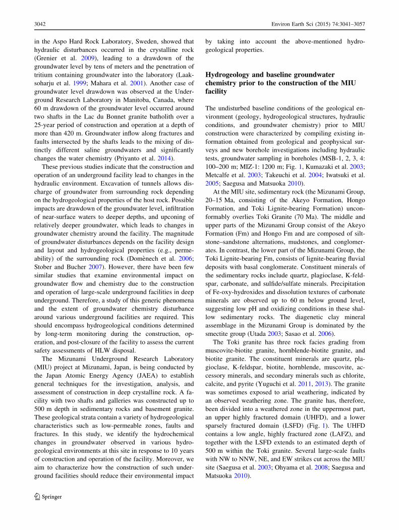
100–200 m; MIZ-1: 1200 m; Fig. 1, Kumazaki et al. 2003;
Metcalfe et al. 2003; Takeuchi et al. 2004; Iwatsuki et al.
2005; Saegusa and Matsuoka 2010).
At the MIU site, sedimentary rock (the Mizunami Group,
20–15 Ma, consisting of the Akeyo Formation, Hongo
Formation, and Toki Lignite-bearing Formation) uncon-
formably overlies Toki Granite (70 Ma). The middle and
upper parts of the Mizunami Group consist of the Akeyo
Formation (Fm) and Hongo Fm and are composed of silt-
stone–sandstone alternations, mudstones, and conglomer-
ates. In contrast, the lower part of the Mizunami Group, the
Toki Lignite-bearing Fm, consists of lignite-bearing fluvial
deposits with basal conglomerate. Constituent minerals of
the sedimentary rocks include quartz, plagioclase, K-feld-
spar, carbonate, and sulfide/sulfate minerals. Precipitation
of Fe-oxy-hydroxides and dissolution textures of carbonate
minerals are observed up to 60 m below ground level,
suggesting low pH and oxidizing conditions in these shal-
low sedimentary rocks. The diagenetic clay mineral
assemblage in the Mizunami Group is dominated by the
smectite group (Utada 2003; Sasao et al. 2006).
The Toki granite has three rock facies grading from
muscovite-biotite granite, hornblende-biotite granite, and
biotite granite. The constituent minerals are quartz, pla-
gioclase, K-feldspar, biotite, hornblende, muscovite, ac-
cessory minerals, and secondary minerals such as chlorite,
calcite, and pyrite (Yuguchi et al. 2011, 2013). The granite
was sometimes exposed to arial weathering, indicated by
an observed weathering zone. The granite has, therefore,
been divided into a weathered zone in the uppermost part,
an upper highly fractured domain (UHFD), and a lower
sparsely fractured domain (LSFD) (Fig. 1). The UHFD
contains a low angle, highly fractured zone (LAFZ), and
together with the LSFD extends to an estimated depth of
500 m within the Toki granite. Several large-scale faults
with NW to NNW, NE, and EW strikes cut across the MIU
site (Saegusa et al. 2003; Ohyama et al. 2008; Saegusa and
Matsuoka 2010).
3042 Environ Earth Sci (2015) 74:3041–3057
123

A B
C D
–1200
–1000
–800
–600
–400
–200
0 250 500 0 400 800 0 10 20 0 5 10 0 1000 20000 1 2 3 4 0 10 20
Na K Ca DIC SO4 F Cl
Dep
th (
m)
The error is within the range of circle.
Fig. 1 Geology and layout of monitoring boreholes at the ground surface, and groundwater chemistry in granite determined by borehole
investigations at MIZ-1 prior to facility construction
Environ Earth Sci (2015) 74:3041–3057 3043
123

Cross-hole hydraulic testing (i.e., long-term pumping in
MIZ-1 and monitoring in DH-2, DH-15, and MSB bore-
holes, as shown in Fig. 1) was conducted by Daimaru et al.
(2010) and Onoe et al. (2011) to determine the hydro-
geological structure around the MIU site. They showed that
the dominant groundwater flow paths are in the basal
conglomerates of the Akeyo/Hongo Fms and the Toki
Lignite-bearing Fm. They also identified hydraulic
boundaries due to the presence of clay layers (with
relatively low hydraulic conductivity) throughout the
sedimentary rock and some faults.
Hydraulic heads in the main part of Akeyo Fm are
30–50 m higher than those in the basal conglomerate of the
deeper Hongo Fm, whereas chemically distinct ground-
waters in the Akeyo Fm (Na–Ca–HCO3 type), which are
rich in silicon and sulfate ions, contrast with groundwater
in the Toki Lignite-bearing Fm and the uppermost part of
the granite (Na–Ca–Cl type). These findings also indicate
that the low-permeability clay layer in the Akeyo Fm and
Hongo Fm is likely to act as a hydraulic barrier. The Na–
Ca–HCO3-type groundwater is believed to have originated
as meteoric water with subsequent evolution due to water–
rock interactions. The residence time of groundwater in the
deeper part of the Akeyo and Hongo Fms is estimated to be
approximately 9.3 ka B.P. (Iwatsuki et al. 2005).
In the Toki granite, groundwater chemistry is dominated
by Na–Ca–Cl. Baseline chemical profiles at MIZ-1 bore-
hole are shown in Fig. 1. It was found that the salinity of
the groundwater generally increases with depth, whereas
the concentrations of SO4, F, and DIC decrease to almost
zero mg/L with depth. Major solute ions such as Na, Ca,
and K relate well with Cl. Groundwater salinity at 1000 m
depth in the granite in and around the MIU site is
2500 mg 1-1 (about one tenth that of seawater); however,
the origin and residence time of the deep saline ground-
water are still unclear.
Facility construction and hydrochemicalmonitoring methods
After investigating the geology, rock strength, hydraulic
conditions, and groundwater chemistry, the underground
facility was constructed up to a depth of 500 m and com-
pleted by the end of March 2013. Figure 2 shows the layout
of shafts and galleries of the MIU facility and monitoring
boreholes drilled from the galleries. The design of the
underground facility consists of main shaft (6.5 m in di-
ameter) and ventilation shaft (4.5 m in diameter). There are
two Access/Research galleries, each at 300 and 500 m
below ground level, and substages at 100 m depth between
the two shafts. The length of ‘‘300 m Access/Research
Gallery’’ and ‘‘500 m Access/Research Gallery (North)’’ is
about 100 and 150 m, respectively. The shafts had been
excavated by two 1.3-m blasting and mucking cycles fol-
lowed by the emplacement of a concrete liner in every
2.6 m section of the shaft (Shimono et al. 2004). Pre-ex-
cavation grouting of a water-conducting fracture zone was
performed at the depths of 191–251 m, 421–428 m, and
446–453 m in the ventilation shaft and at 300 m Access/
Research Gallery. Since the start of the excavation in 2003,
the shafts have been excavated to a total depth of 500 m.
From October 2005 to February 2006, when the shafts had
been excavated to 180 m depth (uppermost part of granite),
groundwater discharge from the shafts had to be reduced
while the effluent treatment facility was being expanded.
As a result, the shafts were temporarily flooded by
groundwater up to 50 m below ground level.
Water collection rings (WR) were placed every 25 m in
the shafts to direct water inflow and reduce water pressure
on the concrete lining. The WR system is also available to
observe the inflow rate and collect groundwater samples at
depth. Periodic monitoring of groundwater pressure and
chemistry was conducted in monitoring boreholes from the
surface (MSB-2, MSB-4, and MIZ-1 in Fig. 1), galleries
(07MI07, 09MI20, 09MI21, 10MI26, 12MI33 in Fig. 2),
and in the WRs (41 sampling points) to monitor the hy-
drochemical disturbance caused by facility construction
and operation. The monitoring zones of each borehole and
the location of WRs are presented in Table 1. Groundwater
was collected under closed-system conditions using either:
(a) a multi-level groundwater monitoring system (Westbay
MP system); (b) stand-pipe multi-packer system (Solex-
perts SPMP system); or (c) continuous hydrochemical
monitoring system (JAEA CHM system). In each of these
boreholes, uranine, amino G. acid, and sodium naph-
thionate were used as tracers, as a quality control measure,
to ensure that water samples were not contaminated with
residual drill fluid. The groundwater from WRs in contact
with the concrete liner was collected under open-system
conditions.
All water samples were filtered using 0.45-lm mem-
brane filters prior to chemical analyses. Tracer concentra-
tions were measured by a fluorescence spectrophotometer
(HITACHI F-3000) with a precision of ±10 %. The con-
centrations of Na, K, Ca, Mg, F, Cl, and SO4 were analyzed
by ion chromatography (Dionex ICS-1000). Water samples
for total-Fe, Si, Al were first adjusted to pH 2 and then
measured by inductively coupled plasma atomic emission
spectrometry (ICP-AES; RIGAKU CIROS-Mark II). Fe2?,
S2-, total carbon, and dissolved inorganic carbon (DIC)
were analyzed by ultraviolet and visible light spectropho-
tometry (SHIMADZU UVmini-1240) and a TOC meter
(Analytikjena multi-N/C 2100S) with a precision of
±10 %. dD and d18O were analyzed by mass spectrometry
(Iso Prime) with a precision of ±0.1 %. Tritium
3044 Environ Earth Sci (2015) 74:3041–3057
123

concentration was measured using a scintillation counter
with a detection limit of 0.3 TU. Chlorofluorocarbons
(CFCs) in the groundwater were collected by purging and
trapping along a vacuum line system and analyzed by gas
chromatography using an electron capture detector (SHI-
MADZU GC-8A) with a precision of 2 %. Multivariate
numerical analysis principal component analysis (PCA)
was conducted on all these data to characterize the che-
mical processes in this system.
Results and discussion
Environmental impact zones around the underground fa-
cility are classified into an Excavation Damaged Zone
(EDZ) near the tunnel and an Excavation disturbed Zone
(EdZ) comprising the EDZ and areas around the excava-
tions (Olsson and Winberg 1996; Bossart et al. 2002; Tsang
et al. 2005). In an EDZ, mechanical and hydrogeological
properties of the rock were intensely fractured during ex-
cavation, and the chemical properties were also modified
by shotcrete, grouting, and air circulation. Hydrochemistry
of the groundwater in the EDZ is unlikely to recover to pre-
construction values, even after the facility closes (Cai et al.
2001; Marty et al. 2009; Berner et al. 2013; Kosakowski
and Berner 2013). In an EdZ, groundwater chemistry is
possibly altered because of the mixing of chemically dis-
tinct waters induced by post-construction changes in the
hydraulic properties of the host rock. However, hydraulic
and chemical disturbances could possibly recover some-
time after facility closure by re-saturation of the open
space. This study focused on the hydraulic disturbance and
induced chemical change in EdZ and their resulting hy-
drogeological structure.
Hydraulic disturbances due to groundwater inflow
in the shaft and gallery
The geology intersected by the shafts is shown in Fig. 2.
The unconformity between Mizunami Group and Toki
granite occurs at approximately 170 m depth in both the
shafts. The boundary between the UHFD and LSFD in
granite is considered to be at approximately 450–500 m
depth. An NNW striking, vertical fault observed during
Fig. 2 Layout of water collection ring and hydrochemical monitoring
boreholes in shafts and galleries, and total volume of groundwater
inflow into the shafts and galleries up to 2013. Since the recent
excavation of the gallery, there are no data of inflow into the 500 m
Access/Research Gallery
Environ Earth Sci (2015) 74:3041–3057 3045
123

Table
1Monitoringintervalsin
each
borehole
andmonitoringmethods
Borehole
(Elevation)
ZoneNo.
Monitoringinteraval
Geology
Method
Meter
alongborehole
Elevation(m
)
MSB-2
(E.L.:198.5
m)Verticalborehole
118.8
22.7
179.7
175.8
AkeyoFm.(W
eathered
zone)
Multilevel
groundwater
monitoringin
amultiport
system
(Westbay
MPsystem
)2
23.6
38.9
174.9
159.6
AkeyoFm.(M
udstone)
3a
39.8
68.2
158.7
130.3
AkeyoFm.,HongoFm.
(Mudstone)
469.1
77.4
129.4
121.1
HongoFm.(Conglomerate)
5a
78.3
120.2
120.2
78.3
Tokilignite-bearingFm.
6121.1
130.4
77.4
68.1
Tokilignite-bearingFm.(Basal
conglomerate)
7131.3
153.7
67.2
44.8
Tokilignite-bearingFm.(Basal
conglomerate)
8154.6
170.4
43.9
28.1
Tokilignite-bearingFm.(Basal
conglomerate)
9171.3
175.2
27.2
23.3
Tokigranite(W
eathered
zone)
MSB-4
(E.L.:214.4
m)Verticalborehole
115.8
25.6
201.6
191.8
AkeyoFm.(M
udstone)
Multilevel
groundwater
monitoringin
amultiport
system
(Westbay
MPsystem
)2
26.5
33.9
190.9
183.5
AkeyoFm.(M
udstone)
334.8
62.1
182.6
155.3
AkeyoFm.,HongoFm.
(Mudstone)
463.0
76.9
154.4
140.5
HongoFm.(Conglomerate)
577.8
81.7
139.6
135.7
Tokilignite-bearingFm.
682.6
93.9
134.8
123.5
Tokilignite-bearingFm.
794.8
99.0
122.6
118.4
Tokigranite(W
eathered
zone)
MIZ-1
(E.L.:206.6
m)Inclined
borehole
91148.8
1169.8
-922.1
-942.5
Tokigranite(LSFD)
Stand-pipemultipacker
system
s(Solexperts
SPMP
system
)
07MI07(E.L.:1.8
m)Horizontalborehole
148.1
55.3
-2.1
-2.6
Tokigranite(U
HFD)
Continuoushydrochem
ical
monitoringsystem
(JAEA
CHM
system
)2
38.7
47.2
-1.3
-2.0
Tokigranite(U
HFD)
331.3
37.8
-0.7
-1.2
Tokigranite(U
HFD)
426.9
30.4
-0.4
-0.6
Tokigranite(U
HFD)
516.9
26.0
0.4
-0.3
Tokigranite(U
HFD)
60.0
16.0
1.8
0.5
Tokigranite(U
HFD)
09MI20(E.L.:-97.8
m)Horizontalborehole
196.1
101.9
-102.8
-103.1
Tokigranite(U
HFD)
Continuoushydrochem
ical
monitoringsystem
(JAEA
CHM
system
)2
84.7
95.2
-102.2
-102.8
Tokigranite(U
HFD)
358.7
83.8
-100.9
-102.2
Tokigranite(U
HFD)
434.8
57.8
-99.6
-100.8
Tokigranite(U
HFD)
519.4
33.9
-98.8
-99.6
Tokigranite(U
HFD)
60.0
18.5
-97.8
-98.8
Tokigranite(U
HFD)
09MI21(E.L.:-98.2
m)Horizontalborehole
10.0
66.1
-98.2
-101.7
Tokigranite(LSFD)
Continuoushydrochem
ical
monitoringsystem
(JAEA
CHM
system
)2
67.1
77.1
-101.7
-102.2
Tokigranite(LSFD)
378.1
88.1
-102.3
-102.8
Tokigranite(LSFD)
489.0
103.0
-102.9
-103.6
Tokigranite(LSFD)
3046 Environ Earth Sci (2015) 74:3041–3057
123

Table
1continued
Borehole
(Elevation)
ZoneNo.
Monitoringinteraval
Geology
Method
Meter
alongborehole
Elevation(m
)
10MI26(E.L.:-197.4
m)
Horizontalborehole
152.8
70.6
-195.5
-194.9
Tokigranite(U
HFD)
Continuoushydrochem
ical
monitoring
system
(JAEA
CHM
system
)2a
50.6
51.8
-195.6
-195.5
Tokigranite(U
HFD)
337.9
49.6
-196.0
-195.6
Tokigranite(U
HFD)
430.2
36.9
-196.3
-196.1
Tokigranite(U
HFD)
510.0
29.2
-197.0
-196.3
Tokigranite(U
HFD)
60.0
9.0
-197.4
-197.0
Tokigranite(U
HFD)
12MI33(E.L.:-297.8
m)
Horizontalborehole
1105.40
107.00
-303.3
-303.4
Tokigranite(LSFD)
Continuoushydrochem
ical
monitoring
system
(JAEA
CHM
system
)2a
85.70
104.40
-302.3
-303.3
Tokigranite(LSFD)
3a
64.00
84.80
-301.1
-302.2
Tokigranite(LSFD)
4a
53.80
63.10
-300.6
-301.1
Tokigranite(LSFD)
544.10
52.90
-300.1
-300.6
Tokigranite(LSFD)
60.00
43.20
-297.8
-300.1
Tokigranite(LSFD)
Water
collectionring(Elevationofshaftpoint:200.9m)
Manually
water
collectionin
theshafts
Mainshaft
A-W
R-1
190.9
Ventilationshaft
B-W
R-1
189.3
Alluvium
A-W
R-2
158.4
B-W
R-2
161.4
AkeyoFm.(M
udstone)
A-W
R-3
123.9
B-W
R-3
132.4
HongoFm.(Conglomerate)
A-W
R-4
a106.5
B-W
R-4
106.9
Tokilignite-bearingFm.
(Carbonaceousmud/sandstone)
A-W
R-5
a98.3
B-W
R-5
98.3
Tokilignite-bearingFm.(Carbonaceousmud/
sandstone)
A-W
R-6
64.7
B-W
R-6
69.7
Tokilignite-bearingFm.(Basal
conglomerate)
A-W
R-6
(1)
49.1
Tokilignite-bearingFm.(Basal
conglomerate)
A-W
R-7
33.5
B-W
R-7
35.9
Tokilignite-bearingFm.(Basal
conglomerate)
A-W
R-8
6.5
B-W
R-8
9.9
Tokigranite
A-W
R-9
-1.7
B-W
R-9
0.9
Tokigranite
A-W
R-10
-35.3
B-W
R-10
-30.3
Tokigranite
A-W
R-11
-63.9
B-W
R-11
-64.1
Tokigranite
A-W
R-12a
-93.5
B-W
R-12
-93
Tokigranite
A-W
R-13
-101.7
B-W
R-13
-101.7
Tokigranite
A-W
R-14
-135.3
B-W
R-14
-130.3
Tokigranite
A-W
R-15
-171.1
B-W
R-15
-164.1
Tokigranite
A-W
R-16
-193.5
B-W
R-16
-193
Tokigranite
A-W
R-17
-204.3
B-W
R-17
-201.7
Tokigranite
A-W
R-18
-235.3
B-W
R-18
-230.3
Tokigranite
A-W
R-19
-263.7
B-W
R-19
-264.1
Tokigranite
A-W
R-20
-293.5
B-W
R-20
-292.1
Tokigranite
Elevation:abovemeter
sealevel
aTherearenodataat
thepointwherewater
inflow
islow
orrecentlyinstalledmonitoringsystem
Environ Earth Sci (2015) 74:3041–3057 3047
123

surface-based investigations is intersected by the main
shaft. This fault, ‘‘the main shaft fault (MSF),’’ has an
abundance of clay materials, which is the possible reason
for the low hydraulic permeability of the fault. To evaluate
hydrogeological properties, the cross-hole pumping test on
both the sides of the MSF was conducted in boreholes
penetrating the fault drilled from the 300 m Access/Re-
search Gallery. The test indicated that the MSF acts as a
flow barrier, normal to the fault plane, and may have re-
duced the degree of hydraulic disturbance during facility
construction (Onoe et al. 2011). It also indicated that the
granite has high hydraulic connectivity associated with
water-conducting fractures and that a hydrogeological
compartment is formed with low-permeability structures
such as faults or clay layers in the sedimentary rock on both
the sides of the MSF.
During shaft excavation, groundwater inflow into the
excavations was in the order of hundreds of cubic meters a
day. Figure 2 shows the total water inflow observed at each
WR until 2013. The highest water inflow into the ventila-
tion shaft of more than 3 9 105 m3 occurred from the
conglomerate layer in the Toki Lignite-bearing Fm (WR-
7). The inflow at other depths in the sedimentary rock,
mainly from sand–clay layers, was significantly low when
compared with this conglomerate layer in the Toki Lignite-
bearing Fm. This conglomerate layer is most likely to be
the dominant groundwater flow path in the sedimentary
rock. The water inflow increased at the top of the granite
becoming higher at WR-8 and WR-9, corresponding to
weathered granite below the unconformity or LAFZ and at
the 300 m Access/Research Gallery on the north side of the
MSF. The connectivity and continuity of the fractures of
LAFZ may be higher than those of UHFD other than
LAFZ. The water inflow volume of approximately 3 9 105
m3 at the 300 m Access/Research Gallery is higher than
that in both shafts in the granite due to differences in the
encounter rate of excavations and fractures in granite. The
statistical distribution of fracture dip in the granitic rock
mass is currently unknown, but should be investigated to
examine the excavation layout of low water inflow in fu-
ture research. The water inflow volume into the main shaft
tends to be small compared to flows into the ventilation
shaft. Such differences are attributed to the low perme-
ability of the MSF.
Hydraulic drawdown occurs at the borehole up to 500 m
from the ventilation shaft (DH-15; Fig. 1, Daimaru et al.
2010). In this study, groundwater chemistry was observed
at monitoring boreholes (MSB-2, MSB-4, MIZ-1, 07MI07,
09MI20, 09MI21, 10MI26, 12MI33; Figs. 1, 2) within an
area of approximately 200 m away from shafts. Figure 3
shows the water pressure in each monitoring zone except
for 12MI33, which was drilled recently. Water pressures in
zones 1 and 2 of MSB-2, zones 1, 2, and 3 of MSB-4, and
zone 3, 6, and 9 of MIZ-1 are less variable than those in
zones 3–9 of MSB-2 and zones 4–7 of MSB-4, which
clearly changed in response to shaft excavation. In the
latter zones, water pressures temporally recovered during
the shaft flooding (between October 2005 and February
2006) and have been subsequently decreasing ever since.
Drawdown at 700-800 kPa and 300-400 kPa pressure from
baseline conditions occurred at the boundary between the
conglomerate layer and the weathered granite in MSB-2
(zones 6–9) and MSB-4 (zones 4–7), respectively. Water
pressures in zones 4, 6, and 7 of MSB-4 were below at-
mospheric pressure. This suggests that the amount of water
inflow from these geological formations to the shafts is
larger than the groundwater recharge rates into these for-
mations, and thus, the groundwater resource is depleting.
These monitoring zones correspond to WRs with large
inflow volumes [WR-6, WR-6(1) and WR-7; Figs. 1, 2].
The low-permeability clay layer in the sedimentary rock
above acts as a hydraulic barrier and prevents the influence
of shaft excavations on the shallow subsurface groundwater
system.
Conversely, the boreholes drilled horizontally from
galleries in granite were used to estimate drawdown with
increasing lateral distance from the galleries. The
monitoring results suggest that water pressures in the range
of 100 m from the galleries decrease to 1.0-1.5 MPa
compared to the baseline conditions (Fig. 3). A similar
decrease in water pressures is observed in all the
monitoring zones in the 07MI07 borehole drilled from the
200 m stage. The water pressure in zone 6 near the gallery
particularly decreases in 09MI20 and 10MI26 boreholes
drilled from the 300 m and 400 m stages, respectively.
Furthermore, the drawdowns in the 09MI21 borehole on
the 300 m Access/Research Gallery, drilled on the north
side of the MSF, are less than those in the 09MI20 bore-
hole, and the drawdown is larger on the south side of the
MSF compared to the north side. Any potential hydraulic
impact due to the ventilation shaft is shielded by the MSF,
from impacts on the north side of the fault.
Groundwater chemistry in the WRs is likely to vary due
to water–cement interaction as a result of contact with the
concrete liner. Incidentally, Cl is not susceptible to water–
mineral interaction, and variations in Cl concentration in
WRs are shown in Fig. 4. Cl concentrations are higher in
WR 6–10 in the main shaft compared to baseline concen-
trations, and the temporal variations are reduced compared
to those observed in WR 15–18. These WRs roughly cor-
respond to the conglomerate, weathered granite, and
LAFZ, which have large inflow volumes (Fig. 2). Cl con-
centration in WR 15–18 tends to increase with time
(Fig. 4), which is possibly due to upconing of relatively Cl-
rich water from depth. The change of Cl concentration in
WR 19 and 20 is small and represents the LSFD. At sites
3048 Environ Earth Sci (2015) 74:3041–3057
123

deeper than WR 10 of the ventilation shaft, Cl concentra-
tions are higher than those in WRs at similar depths of the
main shaft (Fig. 4). The magnitude of upconing around the
ventilation shaft could be larger than around the main shaft,
which is associated with an increased volume of water
inflow into the ventilation shaft (Fig. 2). Cl concentrations
in these WRs increased during the initial observation pe-
riod but subsequently decreased with time. The WRs were
sequentially installed in the deepest part of the shaft as the
excavation progressed, and therefore, the observation at
each WR is affected by upconing in the initial period. In-
crease in Cl concentrations from baseline levels due to
upconing is observed to be in the order of several tens to
hundreds mg 1-1 in the ventilation shaft. Groundwater
movement by upconing is illustrated using these ground-
water chemistry data. For example, Cl concentration at WR
13 (300 m depth) in the ventilation shaft was ap-
proximately 250 mg 1-1 during upconing periods (De-
cember 2009; Fig. 4). This value corresponds to Cl
concentrations observed at approximately 450 m depth
prior to shaft excavation. It implies that groundwater from
approximately 150 m below moved upward to the bottom
of the shaft. As excavation of the shaft advances to deeper
depths, the upconing point moves to deeper depths.
Meanwhile, in the upper depths, upconing is reduced and
the impact of shallow groundwater infiltration increases
with time. The shallow groundwater with comparatively
lower Cl concentrations infiltrates to depth around the
-2000
200400600800
100012001400
zone 2zone 3zone 4zone 5zone 6zone 7zone 8zone 9
0
1000
2000
0
1000
2000
0
1000
2000
0
1000
2000
3000
MSB-2
-200
0
200
400 MSB-4
07MI07
09MI20
09MI21
10MI26
Time
Wat
er p
ress
ure
(kP
a)
zone 6
zone 1-5
zone 6
zone 1-5
zone 1-4
zone 1-6
0
5000
10000
15000MIZ-1
Fig. 3 Water pressures in
monitoring boreholes during
facility construction and
operation
Environ Earth Sci (2015) 74:3041–3057 3049
123

ventilation shaft and dilutes the salinity of infiltrating
groundwater. In contrast, the influence of the upconing and
subsequent shallower groundwater infiltration appears to be
suppressed around the main shaft by the presence of a low-
permeability altered fracture zone located around the MSF.
One finding is that the extent of hydrochemical distur-
bances resulting from the MIU facility construction and
operation depends on the distribution of hydrogeological
structures such as these low-permeability clay layers,
conglomerates, and faults.
Trends in groundwater hydrochemistry
Monitoring boreholes at the surface
Figure 5 shows groundwater chemistry trends in all
monitoring boreholes drilled from surface. Water–mineral
interactions occur between the groundwater derived from
deeper or shallower depths and fracture surface minerals
including fresh minerals in newly created flow paths by
excavation and engineering materials such as cement.
Nevertheless, chemical components which vary with Cl
concentrations are largely due to the mixing process of
groundwaters with distinct salinity. The correlations be-
tween concentrations of Cl and other elements are shown in
the Online Resource 1.
Cl concentration in MSB boreholes is variable due to the
presence of clay layers (Table 1; Fig. 5). However, the hy-
drochemical influence of the facility construction is likely to
extend deeper than low-permeability clay layers. At site
MSB-2, Ca, DIC, and SO4 concentrations fluctuate
throughout zone 1 (Fig. 5). Because MSB-2 is located in the
developed land for the MIU facility construction, the var-
iations of Ca, DIC, and SO4 concentrations in zones 1 likely
occur because of the weathering of sulfate and carbonate
minerals in shallow horizons (Iwatsuki et al. 2005).
Groundwater chemistry of zones 8 and 9 observed in the
early observations is similar to those of zones 1 and 2 in
shallow sedimentary rock, which subsequently changed the
chemistry in deep sedimentary rocks (e.g., zones 6 and 7;
Fig. 5 and Online Resource 1). This is because the shallow
groundwater contamination in these relatively permeable
basal conglomerates and weathered granites, which occurred
during borehole drilling and installation of the groundwater
monitoring system, is eliminated over time with long-term
groundwater sampling. During shaft flooding between Oc-
tober 2005 and February 2006, associated changes in ele-
mental concentrations were observed in zones 4–9 because
of reverse infiltration of groundwater flooding in the shafts.
The flood water is likely to be derived from the basal con-
glomerate (WR-7: Fig. 2), which corresponds to zone 7 and
8 of MSB-2 (Fig. 1). Groundwater chemistry in zone 4, 6, 8,
and 9 of MSB-2 tends to approach that of zone 7. The
correlations among Cl concentration and other chemical
components are not obvious in MSB-2 because shaft
flooding possibly caused the mixing of more than two end-
member groundwaters (Online Resource 1).
In the MSB-4, Na, Ca, and Cl concentrations increase
and DIC concentrations decrease in zones 5 and 6 (Toki
Lignite-bearing Fm) with time regardless of shaft flooding.
The change in zone 4 shows a inverse tendency in com-
parison with zone 5 and 6 (Fig. 5). Na, Ca, and Cl con-
centrations in these zones are positively correlated,
whereas DIC, SO4, and Cl concentrations are slightly
-600
-500
-400
-300
-200
-100
0
0 200 400 600 0 200 400 600
Dec. 2007
Dec. 2008
Dec. 2009
Dec. 2010
Dec. 2011
Dec. 2012
Mar. 2013
MIZ-1 (before shaftexcavation)
Chemical change over the years at each depth of Water- collection rings
Cl (mg/L)
Dep
th (
m)
Baseline condition
Main Shaft A Ventilation ShaftWR 1
WR 2WR 3
WR 6
WR 7WR 8WR 9
WR 10WR 11
WR 13WR 14
WR 15WR 16
WR 17WR 18
WR 19WR 20
WR 3WR 4WR 5
WR 6WR 7
WR 8WR 9
WR 10WR 11
WR 12WR 13
WR 14
WR 15WR 16
WR 17WR 18
WR 19WR 20
WR 6(1)
Sandstone/Mudstone/Silt
Low permeable clay layer
Conglomerate
Granite(UHFD)
Granite(LAFZ)
Granite(LSFD)
BFig. 4 Chloride concentration
at water collection rings during
facility construction and
operation
3050 Environ Earth Sci (2015) 74:3041–3057
123

negatively correlated (Online Resource 1). The chemical
variation in these zones predominantly occurs by mixing
between high and low-salinity waters. The groundwater
end-members are either waters of relatively low-salinity or
upconed high-salinity deep water, which also has high Na,
Ca, Cl, and low DIC, SO4 concentrations. The mixing ratio
of the high-salinity deep water probably increases with
time in zones 5 and 6. In contrast, the mixing ratio of the
low-salinity water increases with time in zone 4. Na, Ca,
and Cl concentrations in zone 7 are lower than those in
zones 5 and 6. Here, the groundwater in zones 5 and 6 is
inferred to mix with the high-salinity water derived later-
ally along the conglomerate layer. Further investigation is
necessary with respect to the origin of this high-salinity
water and its flow path. Evidences of hydrochemical dis-
turbance are not observed in zone 9 (1149 m depth) in
borehole MIZ-1.
Monitoring boreholes in the gallery
Groundwater chemistry was monitored from horizontal
boreholes (07MI07, 09MI20, 09MI21, 10MI26, 12MI33,
Fig. 5 Hydrochemical changes of groundwater in MSB-2, 4 and MIZ-1
Environ Earth Sci (2015) 74:3041–3057 3051
123

shown in Figs. 6, 7 and Online Resource 1) drilled from
sub stages and galleries.
The boreholes were drilled horizontally from galleries to
monitor the lateral trends in groundwater hydrochemistry.
The groundwater in zone 6 of boreholes 07MI07 and
12MI33 and zone 1 of borehole 09MI21 has a high pH
(Fig. 6) due to water–cement interactions at the borehole
collar. The Ca and DIC concentrations are variable, re-
gardless of the mixing process operating in these zones
(Online Resource 1). Conversely, there is no alkalization of
groundwater in zone 6 of 09MI20 and 10MI26. Alteration
by cement materials around EDZ appears to depend on
inflow, replacing alkalized groundwater behind the gallery
wall with fresh groundwater. The influence of materials
used in the facility construction on groundwater hydro-
chemistry is possibly limited to the small inflow region.
These changes around EDZ will become significant due to
changes in groundwater residence times once the facility
closes. The observation and analysis of groundwater
chemistry around a closed drift scenario will be the focus
of future research.
In borehole 07MI07 at 200 m depth and 09MI20 at
300 m depth, groundwater initially had relatively high Na,
Ca, Cl and low DIC and SO4 concentrations, which have
subsequently changed to relatively low Na, Ca, Cl and high
DIC, SO4 concentrations (Fig. 7). This tendency is clearly
observed near the borehole collars in the excavations (e.g.,
zone 5 and 6). The groundwater in borehole 10MI26
(400 m depth) also shows a similar trend. Here, Cl, DIC,
and SO4 are correlated, except in zone 1 of borehole
09MI21 (Online Resource 1). The temporal change in
groundwater chemistry occurs by mixing of high- and low-
salinity waters in these monitoring boreholes.
Horizontal monitoring boreholes were sequentially
drilled in the deepest gallery during excavation. Therefore,
the observations at each borehole are affected by upconing
during the initial period. In boreholes 07MI07, 09MI20,
and 10MI26 on the south side of the MSF, groundwater
with relatively high levels of Na, Ca, Cl and low DIC and
SO4 concentrations during early observations is represen-
tative of the upconed water around the ventilation shaft.
Since then, relatively shallow groundwater has infiltrated to
the area around the ventilation shaft and is characterized by
low levels of Na, Ca, and Cl, and high DIC and SO4
concentrations. This process of groundwater replacement is
most likely occurring at a faster rate on the south side of
the MSF than those on the north side of the fault, reflecting
the extent of hydraulic impact (i.e., drawdown of the
09MI20 09MI21 10MI2607MI07 12MI33
CFC
-12
(pg/
L)
6.0
8.0
10.0
12.0
0
1
2
3
0
10
20
30
4040
3
pHTr
itium
(T.
U)
Zone 1 Zone 2 Zone 3 Zone 4 Zone 5 Zone 6
Fig. 6 pH, tritium, and CFC-12 concentration of groundwater in the galleries
3052 Environ Earth Sci (2015) 74:3041–3057
123

groundwater level, as shown in Fig. 3). The particularly
rapid change in groundwater chemistry observed in zone 6
of 10MI26 in 2012 demonstrated the replacement of
relatively low-salinity groundwater due to upconing.
However, such trends are not observed in borehole 09MI21
on the north side of the MSF.
Borehole 09MI21 is located approximately 100 m north
of the MSF and was drilled into LSFD. Hydrochemical
changes in the groundwater here are most likely caused by
mixing with groundwaters at 300 m depth without being
influenced by the upconing along the shaft. In general,
mixing with shallower groundwater becomes the dominant
process on the south side of the MSF, whereas mixing with
deeper groundwater dominates groundwater chemistry on
the north side of the fault. In the deepest borehole
(12MI33) on the north side of the MSF, levels of Na, Ca,
and Cl increase with time as a result of upconing.
The increase in Cl due to upconing during the early stages
of the excavation precludes its use as an index of salinity
dilution by shallow groundwater infiltration. To infer the
infiltration of shallow groundwater as a result of the long-
term drawdown into the shafts, observations of tritium and
chlorofluorocarbons (CFCs) concentrations are used as an
index of surface water infiltration (Fig. 6). Tritium is de-
tected at several monitoring zones even though concentra-
tions drop to zero around 200 m depth prior to shaft
50
100
150
200
250
0
50
100
0
5
10
15
20
0
5
10
15
20
0
200
400
600
20
20
100
09MI20 09MI21 10MI2607MI07 12MI33
Na
(mg/
L)C
a (m
g/L)
DIC
(m
g/L)
SO
4 (m
g/L)
Cl (
mg/
L)
Zone 1 Zone 2 Zone 3 Zone 4 Zone 5 Zone 6
Fig. 7 Hydrochemical changes of groundwater in the galleries
Environ Earth Sci (2015) 74:3041–3057 3053
123

excavations (Iwatsuki et al. 2005). CFC-12was first detected
in 2010, and the concentrations gradually increased with
time as observed in boreholes 07MI07 (200 m depth),
09MI20 and 09MI21 (300 m depth), and 10MI26 (400 m
depth). This implies that surface water containing CFC-12
penetrated up to 400 m depth within a few years. CFC-12
concentration in surface water at the MIU site is ap-
proximately 220 pg/kg. The contamination of surface water
in groundwater is estimated to be approximately 6 % on the
basis of a comparison of CFC-12 concentrations in surface
water and groundwaters. In addition, CFC-12 concentrations
in zones 4 and 5 in borehole 09MI20, zones 1, 2 and, 4 in
borehole 09MI21, and zones 1 and 4 in borehole 10MI26 are
higher than those in the shallower borehole 07MI07. It can be
assumed that surface water has directly penetrated to these
depths via fracture zones or faults. It is difficult to estimate
the continuity and connectivity of water-conducting features
only on the basis of borehole investigations and geological
observations of the gallery walls. Long-term monitoring of
CFC concentrations will provide further insight into the
hydrogeological properties of fractures and faults that are
intersected by monitoring boreholes and galleries.
End-member mixing
As described previously, Cl concentrations are correlated
with other components in groundwaters below the low-
permeability clay layer. Table 2 presents the correlation
coefficients for all the chemical components analyzed in
these groundwater samples. All chemical components ex-
cept for Mg and Si appear to correlate well with Cl.
Principal component analysis (PCA) was performed to
identify the chemical composition of groundwater end-
members using the chemical data obtained from over 1000
groundwater samples located below the low-permeability
clay layer, but excluding the areas considered to have been
contaminated during drilling or subsequently by cement
materials (original data are provided in Online Resource 2).
The variance of seven chemical components (Na, K, Ca,
DIC, SO4, F, and Cl) was analyzed by PCA. The loadings
were evaluated to determine the chemical components re-
sponsible for the observed correlations. The chemical
components with the largest positive and negative loadings
make the biggest contribution (Farnham et al. 2003). The
first principal component (PC 1) and second principal
component (PC 2) values of groundwaters are shown in
Online Resource 3. PC 1 is dominated by Na, Ca, and Cl
concentrations, and PC 2 is dominated by DIC, SO4, and F
concentrations. Almost all the groundwater data plot in the
area is surrounded by following end-members: (A) MIZ-1
(1150 m), (B) 09MI21 (300 m), and (C) 07MI07 (200 m).
The chemical composition of all end-members is shown
in Table 3. The groundwater in borehole MIZ-1 prior to
facility construction plots on A–B0 (MIZ-1—220 m)-C0
(MIZ-1—115 m) lines. Owing to the lack of data around
300 m depth of MIZ-1, the PCs are not identified for
groundwater at this depth prior to facility construction.
Even so, the data from depths of 650 m (MIZ-1) and 500 m
(12MI33) plot near the A–B (B0) lines, which would imply
the salinity depth profile from 300 to 1150 m.
If the groundwater mixing occurred vertically, PC val-
ues would plot along the A–B (B0) lines. The PC values of
zone 3 in borehole 09MI21 on the north side of the MSF
plot toward A along the A–B line, indicating that the
mixing proportion of relatively deep groundwater increases
over time. The variability in PCs of zone 2 and 4 is
relatively small compared to that of zone 3 because the
connectivity and continuity of fractures in zone 3 may be
larger than those in zone 2 and 4. The PCs of zone 5 and 6
of borehole MSB-4 plots around A–B (B0) lines. These
zones are likely to be connected to the WRs in the con-
glomerate (WR 7), which showed the largest water inflow.
The relatively deep groundwaters in the granite might be
drawing to WR 7 via these conglomerates.
The PC values of boreholes 09MI20 and 10MI26 with
time tend to plot toward end-member C regardless of A–B
(B0) lines. The groundwater in the depths of 300–400 m on
the south side of the MSF is diluted with time due to
mixing with waters of similar chemical composition to
end-member C. The PC values of borehole 07MI07 plot
Table 2 Correlation factor
among chemical components in
monitoring boreholes
Na K Ca Mg DIC S04 F Cl Si
Na 1.00
K 0.65 1.00
Ca 0.82 0.65 1.00
Mg 0.49 0.58 0.26 1.00
DIC -0.53 -0.28 -0.31 0.05 1.00
S04 -0.49 -0.21 -0.25 -0.14 0.80 1.00
F -0.57 -0.36 -0.39 -0.26 0.15 -0.06 1.00
Cl 0.95 0.68 0.95 0.36 -0.50 -0.44 -0.49 1.00
Si -0.06 0.25 0.05 0.03 0.07 0.16 -0.09 -0.01 1.00
3054 Environ Earth Sci (2015) 74:3041–3057
123

close to end-member C during the early period of obser-
vation, but approach A–B (B0) lines in more recent ob-
servations. The cause of this variation is unclear, but the
groundwater in borehole 07MI07 is likely to be derived
from the conglomerates in sedimentary rocks.
Owing to the large volume of groundwater inflow into
the ventilation shaft, low-salinity water with similar
chemistry to end-member C is drawn into depths of
300–400 m over time. The chemical composition of end-
member C is different to baseline groundwater chemistry
in granite, as estimated by MIZ-1 data and in sedimentary
rock (MSB-4). The origin of end-member C is currently
unknown, though it expected that the groundwater
chemistry at 300–400 m depth on the south side of the
MSF will gradually become similar to that of end-member
C if the current facility operation continues into the
future.
Groundwater chemistry in borehole 09MI21 drilled in
LSFD on the north side of the MSF is less than boreholes
07MI07, 09MI20, 10MI26, which are drilled in UHFD on
the south side of the MSF. The impact of facility con-
struction and operation on groundwater chemistry and fu-
ture changes is closely related with the hydrogeological
structure and properties of the host rock. Suitable spatial
density of monitoring stations must take into account the
hydrogeological heterogeneity to estimate future long-term
hydrochemical changes.
Conclusions
A continuous 10-year hydrochemical monitoring program
was established during the construction and operation of
the MIU facility. Observations were obtained up to a depth
of 500 m, and we found that hydrochemical changes in the
granite occurred up to 100 m away from constructed shafts.
Conversely, the chemical disturbance by materials used in
the facility construction on groundwater is limited to the
small inflow region around the gallery. The principal
mechanisms of hydrochemical disturbances are (1) up-
coning of high-salinity deep groundwater around the
deepest part of the shaft and gallery, and (2) infiltration of
low-salinity shallow groundwater. The hydrochemical
changes of groundwater differ on either sides of the MSF.
The hydraulic impact because of the construction and
operation of the large underground facility depends on the
3-dimensional distribution of hydrogeological structures
such as clay layers, conglomerates, faults, fracture zones,
and rock mass with distinct permeability. Conceptualiza-
tion of the architecture of these compartments is essential
when considering the hydrochemical impacts during the
planning stage of underground facilities. In this case, the
presence of low-permeability hydrogeological structure
such as clay layers isolates the biosphere from the under-
ground facility, which may prevent any negative impact on
water resources at surface.
Chemical disturbances occur due to changes in themixing
ratios of chemically distinct groundwaters in response to
hydraulic impacts. During shaft excavation in fractured rock,
groundwater pumping from a shaft causes upconing of
relatively deeper groundwater around the bottomof the shaft.
The deeper, upconed groundwater then resides around the
shaft for several months even after shaft sinking has pro-
gressed to greater depths. The upconed groundwater is
eventually replaced by shallower groundwater due to con-
stant drainage into the shaft. Hydrochemical change of
groundwater can be rapid in cases where large water inflows
are expected during the excavation.
Table 3 Chemical compositions of end-member water
Borehole/Zone No. (depth) Sampling date pH EC Na? K? Ca2? Mg2? DIC SO42- S2-
– mS/m mg/L mg/L mg/L mg/L mg/L mg/L mg/L
A MIZ-1 / Zone9 (1,150 m) 17-09-2009 8.2 590 434.0 3.3 648.9 1.3 2.3 0.1 \0.1
B 09MI21 / Zone3 (300 m) 14-07-2010 8.7 50 86.0 0.3 14.0 \0.1 7.9 1.3 \0.1
C 07MI07 / Zone1 (200 m) 01-07-2011 8.5 38 70.0 0.3 8.2 \0.1 17.0 17.0 0.5
B0 MIZ-1 (220 m) a 09-07-2003 8.9 48 68.1 0.9 11.1 0.1 6.6 8.4 4.5
C0 MIZ-1 (115 m) a 20-04-2003 9.2 35 58.7 0.3 5.9 0.1 9.6 6.8 0.1
Borehole/Zone No. (depth) Sampling date F- Cl- NO 3- NO 2
- Si Al T-Fe Fe2? Mn
mg/L mg/L mg/L mg/L mg/L mg/L mg/L mg/L mg/L
A MIZ-1 / Zone9 (1,150 m) 17-09-2009 3.1 1890 \0.05 \0.05 8.9 0.01 0.024 \0.2 0.109
B 09MI21 / Zone3 (300 m) 14-07-2010 13.0 109 \0.05 \0.05 6.9 0.06 0.075 \0.2 0.004
C 07MI07 / Zone1 (200 m) 01-07-2011 8.4 45 \0.05 \0.05 7.1 \0.01 \0.005 \0.2 \0.003
B0 MIZ-1 (220 m) a 09-07-2003 11.9 85 \0.2 \0.3 4.5 0.89 0.086 \0.05 0.084
C0 MIZ-1 (115 m) a 20-04-2003 8.7 38 \0.2 \0.3 8.6 0.06 0.021 \0.05 0.002
a Iwatsuki et al. (2005)
Environ Earth Sci (2015) 74:3041–3057 3055
123

The monitoring program, including borehole placement,
should take into account the distance from the facility and
the presence of potential hydrogeological compartment
structures such as conglomerates, clay layers, faults, and
fractured zones. In this case, the excavation disturbed the
typical groundwater drawdown area to more than several
hundred meters from the shaft.
To reduce the environmental impact of any underground
facility, it is necessary to maintain groundwater inflow under
control during construction and operation and to allow the
recovery of the groundwater level by closing the facility
prior to the infiltration of large volumes of shallow water.
However, a seamless watertight shotcrete/concrete lining on
the gallery and shaft walls to control inflow may result in an
unexpected increase in inflow due to higher water pressures
developing behind the wall. If this happens, effective sup-
pression of groundwater inflow would be difficult from the
viewpoint of safety. Consequently, understanding hydro-
geological structures prior to facility construction and
planning of shaft and gallery layouts in low-permeability
rock is essential to minimize drawdown of the groundwater
level and consequent hydrochemical impacts.
Future studies of hydrochemical recovery processes in a
variety of hydrogeological settings and facility scales are
required. These studies should also focus on impacts from
artificial materials used around gallery upon groundwater
residence times after facilities have closed.
Acknowledgments The authors wish to thank G. McCrank, an ex-
JAEA International Fellow, for help with manuscript preparation and
advice for this research.
Open Access This article is distributed under the terms of the Crea-
tive Commons Attribution 4.0 International License (http://creative-
commons.org/licenses/by/4.0/), which permits unrestricted use,
distribution, and reproduction in any medium, provided you give
appropriate credit to the original author(s) and the source, provide a link
to the Creative Commons license, and indicate if changes were made.
References
Banwart S, Gustafsson E (1994) Large-scale intrusion of shallow-
water into a vertical fracture-zone in crystalline bedrock—initial
hydrochemical perturbation during tunnel construction at the
aspo-hard-rock- laboratory, Southeastern Sweden. Water Resour
Res 30:1747–1763
Bauer S, Beyer C, Dethlefsen F, Dietrich P, Duttmann R, Ebert M,
Feeser V, Gorke U, Kober R, Kolditz R, Rabbel W, Schanz T,
Schafer D, Wurdemann H, Dahmke A (2013) Impacts of the use
of the geological subsurface for energy storage: an investigation
concept. Environ Earth Sci 70:3935–3943
Berner U, Kulik DA, Kosakowski G (2013) Geochemical impact of a
low-pH cement liner on the near field of a repository for spent
fuel and high-level radioactive waste. Phys ChemEarth 64:46–56
Bossart P,Meier PM,Moeri A, Trick T,Mayor J (2002) Geological and
hydraulic characterisation of the excavation disturbed zone in the
opalinus clay of themont terri rock laboratory. EngGeol 66:19–38
Cai M, Kaiser PK (2005) Assessment of excavation damaged zone
using a micromechanics model. Tunn Undergr Space Technol
20:301–310
Cai M, Kaiser PK, Martin CD (2001) Quantification of rock mass
damage in underground excavations from microseismic event
monitoring. Int J Rock Mech Min Sci 38:1135–1145
Cesano D, Olofsson B, Bagtzoglou A (2000) Parameters regulating
groundwater inflows into hard rock tunnels—a statistical study
of the Bolmen tunnel in southern Sweden. Tunn Undergr Space
Technol 15:153–165
Daimaru S, Takeuchi R, Takeda M, Ishibashi M (2010) Hydro-
geological characterization based on long term groundwater
pressure monitoring. In: Proceedings of 13th international
conference on environmental remediation and radioactive waste
management (ASME 2010):149–158
Domenech C, Arcos D, Duro L (2006) Effect of the mineral
precipitation- dissolution at tunnel walls during the operational
and post-operational phases. SKB Report R-06-108, ISSN
1402-3091
Farnham IM, Johannesson KH, Singh AK, Hodge VF, Stetzenbach KJ
(2003) Factor analytical approaches for evaluating groundwater
trace element chemistry data. Anal Chim Acta 490:123–138
Flint A, Flint L, Kwicklis E, Bodvarsson G, Fabryka-Martin J (2001)
Hydrology of Yucca Mountain, Nevada. Rev Geophys
39:447–470
Font-Capo J, Vazquez-Sune E, Carrera J, Herms I (2012) Ground-
water characterization of a heterogeneous granitic rock massif
for shallow tunneling. Geologica Acta 10:395–408
Gascoyne M, Gascoyne S, Sargent FP (1995) Geochemical influences
on the design, construction and operation of a nuclear waste
vault. Appl Geochem 10:657–671
Grenier C, Bernard-Michel G, Benabderrahmane H (2009) Evaluation
of retention properties of a semi-synthetic fractured block from
modelling at performance assessment time scales (Aspo Hard
Rock Laboratory, Sweden). Hydrogeol J 17:1051–1066
Ii H, Kagami H (1997) Groundwater level and chemistry changes
resulting from tunnel construction near Matsumoto City, Japan.
Environ Geol 31:76–84
Iwatsuki T, Furue R, Mie H, Ioka S, Mizuno T (2005) Hydrochemical
baseline condition of groundwater at the Mizunami underground
research laboratory (MIU). Appl Geochem 20:2283–2302
Joyce S, Hoek J, Serco LH (2010) SR-Site Pre-modelling: Sensitivity
studies of hydrogeological model variants for the Laxemar site
using CONNECTFLOW. SKB Technical Report R-08-108,
Svensk Karnbranslehantering AB
Kosakowski G, Berner U (2013) The evolution of clay rock/cement
interfaces in a cementitious repository for low- and intermediate
level radioactive waste. Phys Chem Earth 64:65–86
Kumazaki N, Ikeda K, Goto J, Mukai K, Iwatsuki T, Furue T (2003)
Synthesis of the shallow borehole investigations at the MIU
construction site. JNC TN7400 2003-005. Japan Nuclear Cycle
Development Institute
Laaksoharju M, Tullborg E, Wikberg P, Wallin B, Smellie J (1999)
Hydrogeochemical conditions and evolution at the Aspo HRL,
Sweden. Appl Geochem 14:835–859
Lee J, Kim RH, Chang HW (2003) Interaction between groundwater
quality and hydraulic head in an area around an underground
LPG storage cavern, Korea. Environ Geol 43:901–912
Lee E, Lim JW, Moon HS, Lee KK (2014) Assessment of seawater
intrusion into underground oil storage cavern and prediction of
its sustainability. Environ Earth Sci. doi:10.1007/s12665-014-
3473-5
Maejima T, Morioka H, Mori T, Aoki K (2003) Evaluation of
loosened zones on excavation of a large underground rock
cavern and application of observational construction techniques.
Tunn Undergr Sp Technol 18:223–232
3056 Environ Earth Sci (2015) 74:3041–3057
123

Mahara Y, Igarashi T, Hasegawa T, Miyakawa K, Tanaka Y, Kiho K
(2001) Dynamic changes in hydrogeochemical conditions caused
by tunnel excavation at the Aspo Hard Rock Laboratory (HRL),
Sweden. Appl Geochem 16:291–315
Martinez-Landa L, Carrera J (2005) An analysis of hydraulic
conductivity scale effects in granite (full-scale engineered barrier
experiment (FEBEX), Grimsel, Switzerland). Water Resour Res
41:1–13
Martinez-Landa L, Carrera J (2006) A methodology to interpret cross-
hole tests in a granite block. J Hydrol 325:222–240
Marty NCM, Tournassat C, Burnol A, Giffaut E, Gaucher EC (2009)
Influence of reaction kinetics and mesh refinement on the
numerical modelling of concrete/clay interactions. J Hydrol
364:58–72
Metcalfe R, Hama K, Amano K, Iwatsuki T, Saegusa H (2003)
Geochemical approaches to understanding a deep groundwater
flow system in the Tono area, Gifu-ken, Japan. In: Nishigaki and
Komatsu (eds.), Groundwater Engineering, A.A. Balkema Pub-
lishers, pp 555–561
Ohyama T, Saegusa H, Onoe H, Guimera J, White MJ, Robinson P
(2008) GEOMASS: The application to characterizations of
groundwater flow in the Mizunami Underground Research
Laboratory project in Tono area. In: Proceedings of 36th IAH
congress, CD-ROM
Olsson OL, Winberg A (1996) Current understanding of extent and
properties of the excavation disturbed zone and its dependence
of excavation method. In: Martino JB, Martin CD (Eds.), Proc.
International Conference on Deep Geological Disposal of
Radioactive Waste 101–112
Onoe H, Takeuchi R, Saegusa H, Daimaru S, Karino T (2011)
Interpretation of Hydrogeological Characteristics based on Data
from Long-Term Cross-Hole Pumping Test. 19th International
Conference on Nuclear Engineering, Proc. ICONE-19-43560
Priyanto DG, Dixon DA, Kim C-S, Korkeakoski P, Villagran JE
(2014) Preliminary modelling of the saturation of a full-sized
clay and concrete shaft seal. Geological Society, London,
Special Publications. doi:10.1144/SP400.38
Saegusa H, Matsuoka T (2010) Final report on the surface-based
investigation phase (Phase I) at the Mizunami Underground
Research Laboratory Project. JAEA-Research 2010-067. Japan
Atomic Energy Agency
Saegusa H, Inaba K, Maeda K, Nakano K, McCrank G (2003)
Hydrogeological modeling and groundwater flow simulation for
effective hydrogeological characterization in the Tono area,
Gifu, Japan. In: Nishigaki, Komatsu (Eds), Groundwater Engi-
neering, A.A. Balkema Publishers, pp 563–569
Sasao E, Ota K, Iwatsuki T, Niizato T, Arthur RC, Stenhouse MJ,
Zhou W, Metcalfe R, Takase H, Mackenzie AB (2006) An
overview of a natural analogue study of the Tono uranium
deposit, central Japan. Geochem Explor Environ Anal 6:5–12
Sato T, Kikuchi T, Sugihara K (2000) In situ experiments on an
excavation disturbed zone induced by mechanical excavation in
Neogene sedimentary rock at Tono mine, central Japan. Eng
Geol 56:97–108
Shimono M, Suzuki S, Taguchi Y, Kamemura K, Sato T, Mikake S
(2004) Risk assessment approach for underground research
laboratory. In: Proceedings of ISRM international symposium:
3rd Asian rock mechanics symposium 359–365
Stober I, Bucher K (2007) Hydraulic properties of the crystalline
basement. Hydrogeol J 15:213–222
Takeuchi S, Shimo M, Doughty C, Tsang C-F (2004) Identification of
the Water-Conducting Features and Evaluation of Hydraulic
parameters using Fluid Electric Conductivity Logging, Proc. 2nd
International Symposium on Dynamics of Fluids in Fractured
Rock:349–354
Thury M, Bossart P (1999) The Mont Terri rock laboratory, a new
international research project in a Mesozoic shale formation, in
Switzerland. Eng Geol 52:347–359
Tsang C-F, Bernier F, Davies C (2005) Geohydromechanical processes
in the Excavation Damaged Zone in crystalline rock, rock salt, and
indurated and plastic clays - in the context of radioactive waste
disposal. Int J Rock Mech Mining Sci 42:109–125
Utada M (2003) Smectite-zeolite envelope surrounding the Tsu-
kiyoshi uranium deposit, Central Japan: a natural analogue
study. Resour Geol 53:293–304
Vales F, Nguyen Minh D, Gharbi H, Rejeb A (2004) Experimental
study of the influence of the degree of saturation on physical and
mechanical properties in Tournemire shale (France). Appl Clay
Sci 26:197–207
Yang FR, Lee CH, Kung WJ, Yeh HF (2008) The impact of tunneling
construction on the hydrogeological environment of ‘‘Tseng-
Wen Reservoir Trans basin Diversion Project’’ in Taiwan. Eng
Geol 103:39–58
Younger PL (2000) Predicting temporal changes in total iron
concentrations in groundwaters flowing from abandoned deep
mines: a first approximation. J Contam Hydrol 44:47–69
Yuguchi T, Amano K, Tsuruta T, Danhara T, Nishiyama T (2011)
Thermochronology and the three-dimensional cooling pattern of
a granitic pluton: an example of the Toki granite, Central Japan.
Contrib Miner Petrol 162:1063–1077
Yuguchi T, Tsuruta T, Hama K, Nishiyama T (2013) The spatial
variation of initial 87Sr/86Sr ratios in the Toki granite, Central
Japan: implications for the intrusion and cooling processes of a
granitic pluton. J. Miner Petrol Sci 108:1–12
Environ Earth Sci (2015) 74:3041–3057 3057
123