Hydro Pneumatic Press Systems -...
12
5.07/1 Hydro Pneumatic Press Systems For ‘PET’ Stretch Blow Moulding Machines Typical Automatic Stretch Blow Moulding Machine for ‘PET’ Bottles Valve Regulator Assembly Cushion (Decelaration) Solenoid Valves Single & Dual Blow Solenoid Valves Open-Close System with Decelaration Valve Hydro Pneumatic Mould Stretch Pin Cylinder Neck Sealing Cylinder with Hollow Shaft
Transcript of Hydro Pneumatic Press Systems -...

5.07/1
Hydro Pneumatic Press SystemsFor ‘PET’ Stretch Blow Moulding Machines
Typical Automatic Stretch Blow
Moulding Machine for ‘PET’ Bottles
Valve Regulator Assembly
Cushion
(Decelaration)
Solenoid Valves
Single & Dual
Blow Solenoid Valves
Open-Close System with
Decelaration Valve
Hydro Pneumatic Mould
Stretch Pin CylinderNeck Sealing Cylinder
with Hollow Shaft
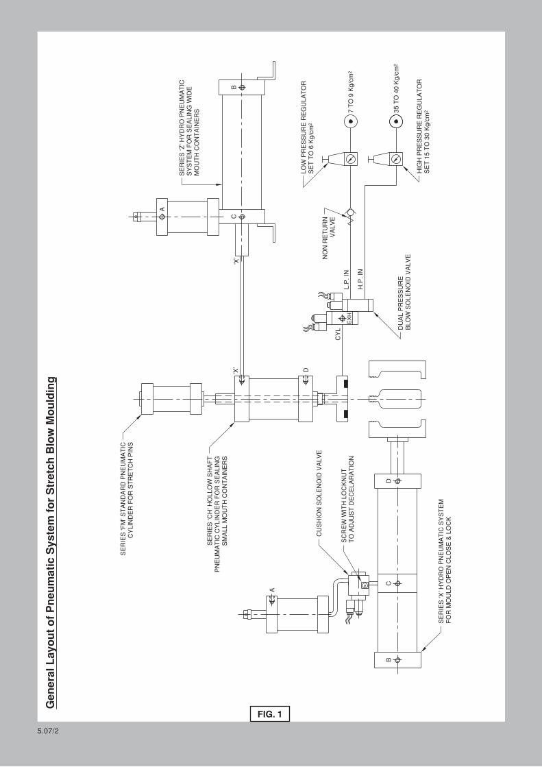
General Layout of Pneumatic System for Stretch B
low M
oulding
FIG. 1
SERIE
S ‘F
M’ STANDARD P
NEUMATIC
CYLIN
DER F
OR S
TRETCH P
INS
SERIE
S ‘CH
’ HOLLOW
SHAFT
PNEUMATIC
CYLIN
DER F
OR S
EALIN
GSMALL M
OUTH C
ONTAIN
ERS
NON R
ETURN
VALVE
CUSHIO
N S
OLENOID
VALVE
SERIE
S ‘X
’ HYDRO P
NEUMATIC
SYSTEM
FOR M
OULD O
PEN C
LOSE &
LOCK
DUAL P
RESSURE
BLOW
SOLENOID
VALVE
HIG
H P
RESSURE R
EGULATOR
2SET 15 T
O 30 K
g/cm
235 T
O 40 K
g/cm2
7 T
O 9 K
g/cm
LOW
PRESSURE R
EGULATOR
2SET T
O 6 K
g/cm
L.P
. IN
H.P
. IN
CYL
EXH
A
DC
B
D‘X’
‘X’
BC
A
SERIE
S ‘Z
’ HYDRO P
NEUMATIC
SYSTEM F
OR S
EALIN
G W
IDE
MOUTH C
ONTAIN
ERS
5.07/2
SCREW
WIT
H LOCKNUT
TO A
DJU
ST D
ECELARATIO
N
1.
(a)
(a)
5.07/3
The general layout of major pneumatic components used in stretch blow moulding machines is given in Fig 1.
“MERCURY” Series “X” and Series “Z” Hydro Pneumatic Clamping Systems use low cost pneumatic elements to achieve the large forces associated with pure hydraulic systems, with 50% saving in energy and 100% increase in speed over an equivalent hydraulic system.
The system has three stages of operation :-
Initial Low force, Large travel, Rapid Approach.
High Force, Short travel (typically 3mm), Power Stroke.
Low Force, Rapid Retraction.
The selection of the correct system is very important for efficient performance. General guidelines is given in the appropriate sections. Please feel free to contact us for further guidance if required.
Sequence of Operation
The heated perform is placed in the mould and the machine cycle is initiated by pressing 2 Hand Safety Push Buttons.
The Series “X” Clamp Cylinder closes the mould at High Speed with a low force (hence low compressed air consumption).
Just 3 to 5mm before the two halves of the mould touch, the Cushion Solenoid Valve is switched “ON”. This Cushions the closing of the mould and avoids banging and machine vibration. The rate of declaration can be varied by adjusting screw on Cushion Solenoid Valve.
After the mould closes completely the Power Stroke Solenoid Valve of Series “X” Cylinder is switched “ON”. This causes the clamping pressure to increase by 20 times the regulated air pressure to Power Stroke Solenoid Valve. The mould is now held in the closed position by a very large force.
The Neck Sealing Cylinder now moves down and seals the neck and Stretch Pin Cylinder extends to stretch the preform to the desired length.
The low pressure solenoid of Dual Pressure Blow Solenoid Valve is switched “ON”, causing initial stretch and blow at low force. After a delay the high pressure solenoid of a Dual Pressure Blow Solenoid Valve is switch “ON” for final blow and forming.
After the set blow time, the air exhausts, and all cylinders retract rapidly.
NOTE :-
General Description
(b)
(c)
The ideal cycle time is 5 to 7 seconds. This can be achieved by proper selection and location of valves and pipe fittings and tubing. Please feel free to contact us with your machine details to enable us to guide you correctly.
1.1
1.2
(b)
(c)
(d)
(e)
(f)
(g)
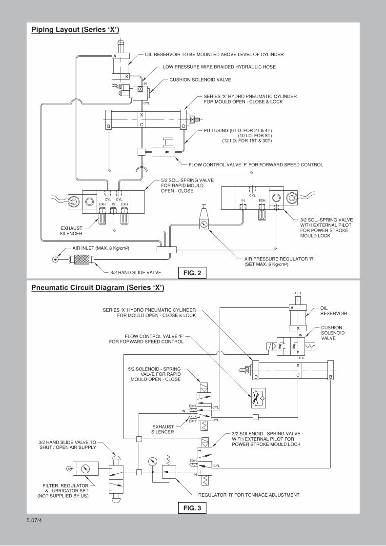
FIG. 3
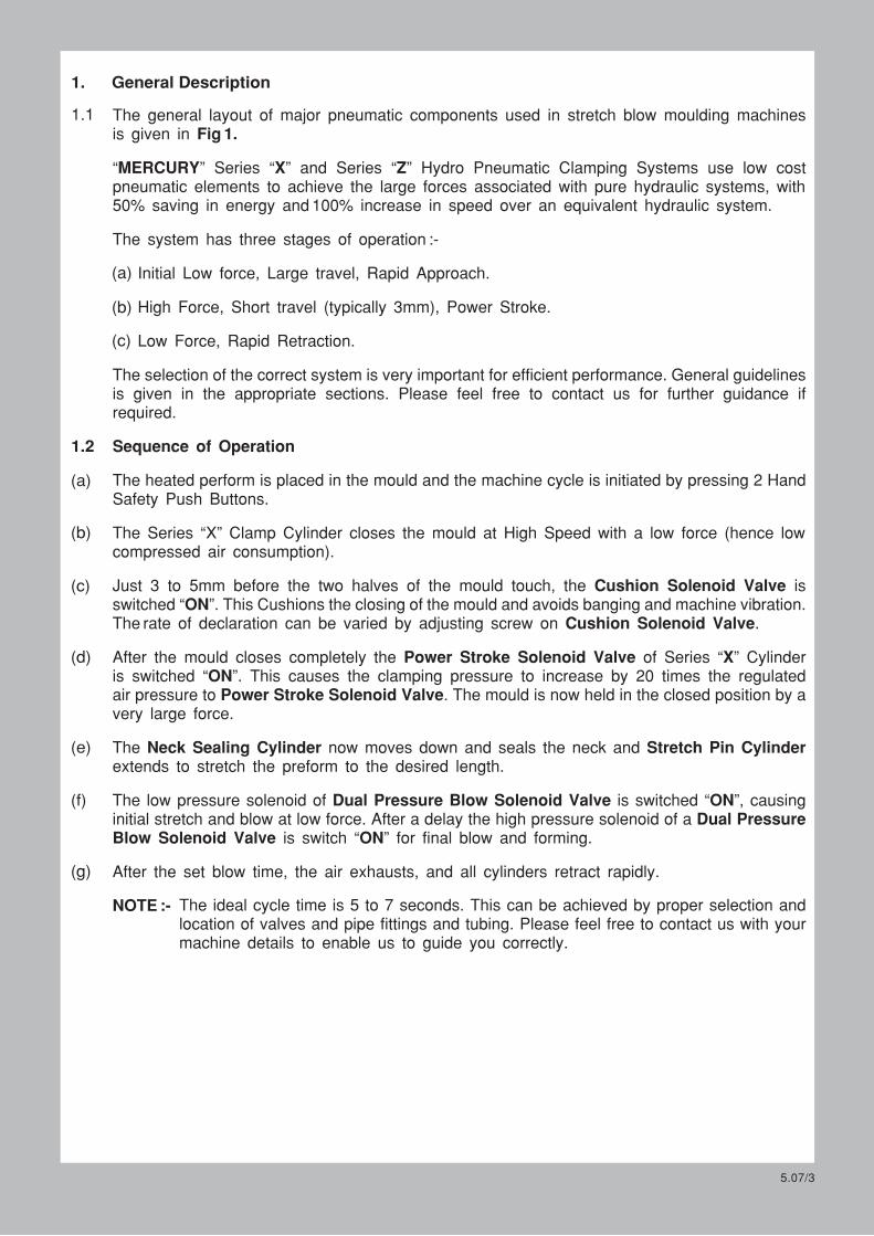
OIL RESERVOIR TO BE MOUNTED ABOVE LEVEL OF CYLINDER
LOW PRESSURE WIRE BRAIDED HYDRAULIC HOSE
CUSHION SOLENOID VALVE
SERIES ‘X’ HYDRO PNEUMATIC CYLINDERFOR MOULD OPEN - CLOSE & LOCK
PU TUBING (6 I.D. FOR 2T & 4T)(10 I.D. FOR 8T)
(12 I.D. FOR 15T & 30T)
FLOW CONTROL VALVE ‘F’ FOR FORWARD SPEED CONTROL
5/2 SOL.-SPRING VALVEFOR RAPID MOULDOPEN - CLOSE
3/2 SOL.-SPRING VALVEWITH EXTERNAL PILOTFOR POWER STROKEMOULD LOCK
AIR PRESSURE REGULATOR ‘R’2(SET MAX. 6 Kg/cm )
3/2 HAND SLIDE VALVE
2AIR INLET (MAX. 8 Kg/cm )
EXHAUSTSILENCER
CYL
EXH
CYL
IN EXH
CYL
IN EXH
SERIES ‘X’ HYDRO PNEUMATIC CYLINDERFOR MOULD OPEN - CLOSE & LOCK
FLOW CONTROL VALVE ‘F’FOR FORWARD SPEED CONTROL
5/2 SOLENOID - SPRINGVALVE FOR RAPID
MOULD OPEN - CLOSE
EXHAUSTSILENCER
3/2 HAND SLIDE VALVE TOSHUT / OPEN AIR SUPPLY
FILTER, REGULATOR& LUBRICATOR SET
(NOT SUPPLIED BY US)
OILRESERVOIR
CUSHIONSOLENOIDVALVE
3/2 SOLENOID - SPRING VALVEWITH EXTERNAL PILOT FORPOWER STROKE MOULD LOCK
REGULATOR ‘R’ FOR TONNAGE ADJUSTMENT
X
A
IN
CYL
CB D
X
X
A
IN
CYL
C BD
X
CYL
CYL
EXH
IN
EXH
CYL
EXH
IN
5.07/4
Piping Layout (Series ‘X’)
FIG. 2
Pneumatic Circuit Diagram (Series ‘X’)
2.
(a)
5.07/5
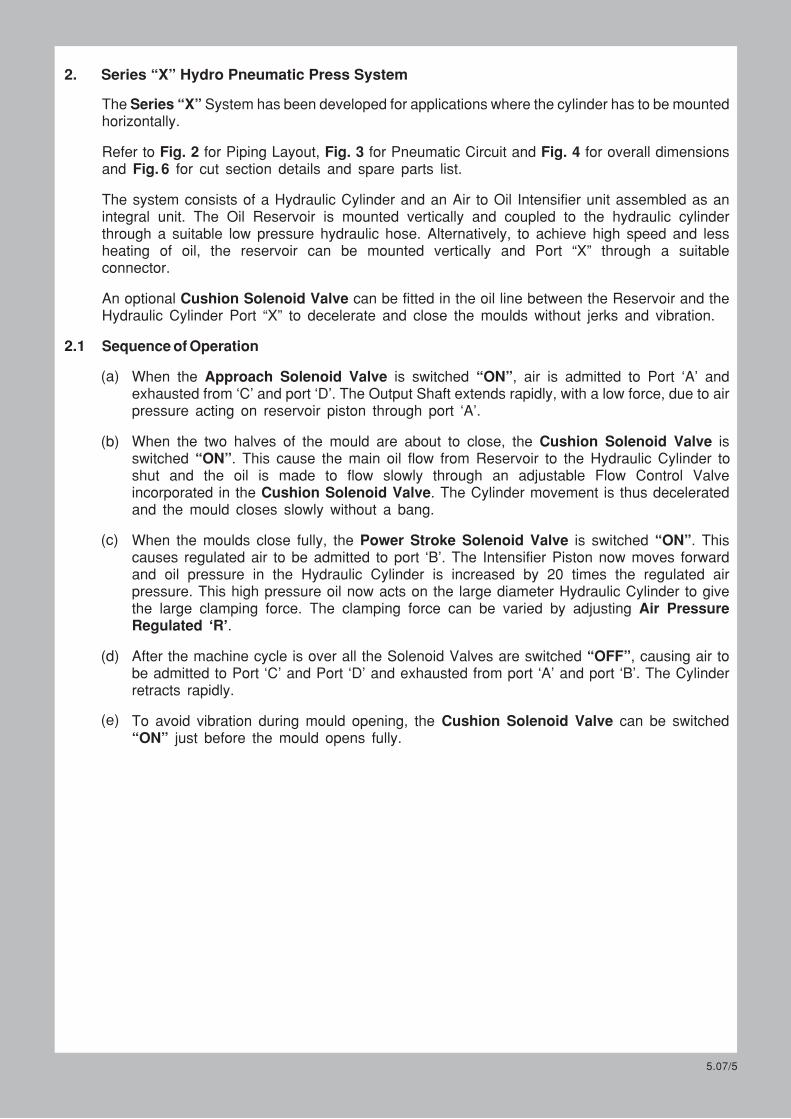
The Series “X” System has been developed for applications where the cylinder has to be mounted horizontally.
Refer to Fig. 2 for Piping Layout, Fig. 3 for Pneumatic Circuit and Fig. 4 for overall dimensions and Fig. 6 for cut section details and spare parts list.
The system consists of a Hydraulic Cylinder and an Air to Oil Intensifier unit assembled as an integral unit. The Oil Reservoir is mounted vertically and coupled to the hydraulic cylinder through a suitable low pressure hydraulic hose. Alternatively, to achieve high speed and less heating of oil, the reservoir can be mounted vertically and Port “X” through a suitable connector.
An optional Cushion Solenoid Valve can be fitted in the oil line between the Reservoir and the Hydraulic Cylinder Port “X” to decelerate and close the moulds without jerks and vibration.
Sequence of Operation
Series “X” Hydro Pneumatic Press System
2.1
(b)
(c)
(d)
(e)
When the Approach Solenoid Valve is switched “ON”, air is admitted to Port ‘A’ and exhausted from ‘C’ and port ‘D’. The Output Shaft extends rapidly, with a low force, due to air pressure acting on reservoir piston through port ‘A’.
When the two halves of the mould are about to close, the Cushion Solenoid Valve is switched “ON”. This cause the main oil flow from Reservoir to the Hydraulic Cylinder to shut and the oil is made to flow slowly through an adjustable Flow Control Valve incorporated in the Cushion Solenoid Valve. The Cylinder movement is thus decelerated and the mould closes slowly without a bang.
When the moulds close fully, the Power Stroke Solenoid Valve is switched “ON”. This causes regulated air to be admitted to port ‘B’. The Intensifier Piston now moves forward and oil pressure in the Hydraulic Cylinder is increased by 20 times the regulated air pressure. This high pressure oil now acts on the large diameter Hydraulic Cylinder to give the large clamping force. The clamping force can be varied by adjusting Air Pressure Regulated ‘R’.
After the machine cycle is over all the Solenoid Valves are switched “OFF”, causing air to be admitted to Port ‘C’ and Port ‘D’ and exhausted from port ‘A’ and port ‘B’. The Cylinder retracts rapidly.
To avoid vibration during mould opening, the Cushion Solenoid Valve can be switched “ON” just before the mould opens fully.
5.07/6
‘N’ (B
.S.P
. AIR
PORTS)
‘X’ (B
.S.P
. OIL P
ORT)
L1 (4 N
os.)
FOR M
OUNTIN
G
BB1
J1 S
Q.
K1 S
Q.
A1
AD
E
C
‘N’ (B
.S.P
. AIR
PORT)
‘N’ (B
.S.P
. AIR
PORT)
‘N’ (B
.S.P
. AIR
PORT)
F T
HDS
ØG
ØH
L (6 N
os.) ON ‘M
’ P.C
.D. FOR M
OUNTIN
G
L (4 N
os.) FOR M
OUNTIN
G
‘H’ THD
’S (FOR LOCKIN
G)
‘F’ THD
’S x ‘J’ D
EEP
2 N
os.
A
G
A1
B
C (MIN
)
AS P
ER C
USTOMER
REQUIR
EMENT
‘L’ SQ.
‘K’ SQ.
ØM
’ THRU H
OLE
‘
ØN
’ DRILL F
LAT x ‘P
’ DEEP
‘
‘R’
(RADIU
S)
ØE
ØE1
ØD
ØD1
+.00
.10
+.10
.00
+.10
.00
+.10
.00
S
‘S’ A/F
FLAT
SPANNER
A
14.8
TON
2
C 58
D
43.8
E
37.8
A1
15
14.8
471
57.8
44.8
15
14.8
878
63.8
49.8
15
14.8
15
98
77.8
64.8
15
19.8
30
134
87.8
74.8
20
B 25
30
30
30
40
D1
44
58
64
78
88
E1
38
45
50
65
75
F
M20x1
.5
M24x2
M36x2
M40x2
M48x3
G 10
10
10
15
15
H
M6x1
M6x1
M6x1
M8x1
.25
M8x1
.25
J 35
40
40
40
45
K 44
52
58
72
80
L 62
75
78
98
105
M 8.5
8.5
10.5
12.5
12.5
N
13.5
13.5
16.5
19
19
P 12
15
15
15
15
R
125
275
375
600
775
S 35
42
46
60
70
K S
Q.
J SQ.
FREE A
IR C
ONSUMED
/ CYCLE IN LTS.
3.5
4.7
6.0
7.2
10.9
13.1
15.3
17.5
21.0
24.5
28.5
32.5
41.3
48.3
57.7
67.3
47.0
56.0
90.0
109.0
TON
2 2 2 2 4 4 4 4 8 8 8 8 15
15
15
15
30
30
30
30
TOTAL
STROKE
100
150
200
250
100
150
200
250
100
150
200
250
100
150
200
250
100
150
200
250
POW
ER
STROKE
3 3 3 3 3 3 3 3 3 3 3 3 3 3 3 3 3 3 3 3
A
381
431
481
531
413
463
513
563
449
499
549
599
454.5
504.5
554.5
604.5
468
518
568
618
A1
15
15
15
15
21
21
21
21
30
30
30
30
35
35
35
35
40
40
40
40
B
150
200
250
300
156
206
256
306
144
194
244
294
167
217
267
317
167
217
267
317
B1
210
260
310
360
227
277
327
377
222
272
322
373
252
302
352
402
248
298
348
398
C 4 4 4 4 4 4 4 4 4 4 4 4 4 4 4 4 4 4 4 4
D 19
19
19
19
22
22
22
22
24
24
24
24
24.5
24.5
24.5
24.5
26
26
26
E 30
30
30
30
35
35
35
35
35
35
35
35
35
35
35
35
40
40
40
40
F
M20x1
.5
M20x1
.5
M20x1
.5
M20x1
.5
M24x2
M24x2
M24x2
M24x2
M36x2
M36x2
M36x2
M36x2
M40x2
M40x2
M40x2
M40x2
M48x3
M48x3
M48x3
G
25.40
25.40
25.40
25.40
31.75
31.75
31.75
31.75
50.80
50.80
50.80
50.80
62.30
62.30
62.30
62.30
62.30
62.30
62.30
62.30
H 45
45
45
45
55
55
55
55
75
75
75
75
90
90
90
90
90
90
90
J 78
78
78
78
108
108
108
108
145
145
145
145
182
182
182
182
205
205
205
J1 65
65
65
65
92
92
92
92
128
128
128
128
168
168
168
168
175
175
175
K 55
55
55
55
78
78
78
78 - - - - - - - - - - - -
K1
52
52
52
52
71.5
71.5
71.5
71.5
100
100
100
100
130
130
130
130
140
140
140
L
M12x1
.75
M12x1
.75
M12x1
.75
M12x1
.75
M16x2
M16x2
M16x2
M16x2
M16x2
M16x2
M16x2
M16x2
M20x2
.5
M20x2
.5
M20x2
.5
M20x2
.5
M24x3
M24x3
M24x3
26
M48x3
90
205
175
140
M24x3
L1
M8x1
.25
M8x1
.25
M8x1
.25
M8x1
.25
M10x1
.5
M10x1
.5
M10x1
.5
M10x1
.5
M12x1
.75
M12x1
.75
M12x1
.75
M12x1
.75
M16x2
M16x2
M16x2
M16x2
M16x2
M16x2
M16x2
M16x2
M - - - - - - - -
105
105
105
105
125
125
125
125
150
150
150
150
N
1/4”
1/4”
1/4”
1/4”
1/4”
1/4”
1/4”
1/4”
1/2”
1/2”
1/2”
1/2”
1/2”
1/2”
1/2”
1/2”
1/2”
1/2”
1/2”
1/2”
X
3/4”
3/4”
3/4”
3/4”
3/4”
1”
1”
1”
1”
1”
1”
1”
3/4”
1”
3/4”
3/4”
1/2”
1/2”
1/2”
1/2”
MODEL
No.
PO20X-1
00
PO20X-1
50
PO20X-2
00
PO20X-2
50
PO40X-1
00
PO40X-1
50
PO40X-2
00
PO40X-2
50
PO80X-1
00
PO80X-1
50
PO80X-2
00
PO80X-2
50
P150X-1
00
P150X-1
50
P150X-2
00
P150X-2
50
P300X-1
00
P300X-1
50
P300X-2
00
P300X-2
50
Flexible C
oupling
Reservoir
Cylinder - Intensifier Unit
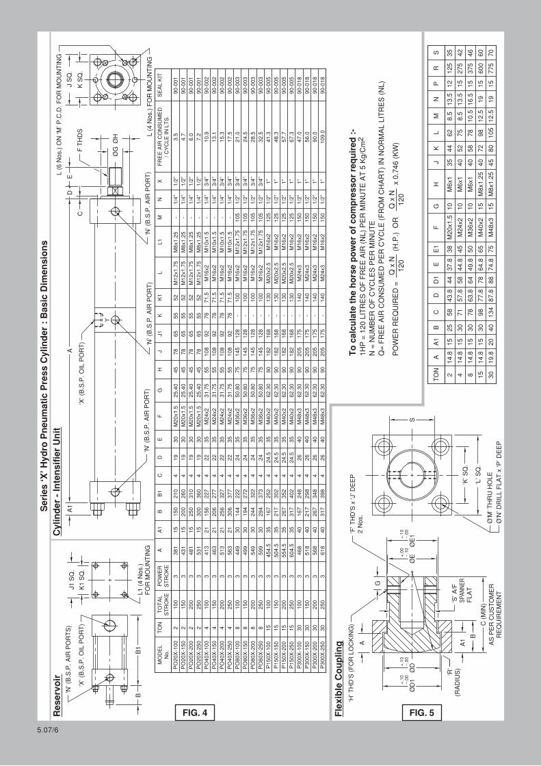
Series ‘X
’ Hydro
Pneumatic Press C
ylinder : Basic D
imensions
POW
ER R
EQUIR
ED = (H.P
.) OR x 0.746 (KW
)Q x N
120
Q x N
120
To calculate the horse power of compressor required :-
21HP = 120 LIT
RES O
F F
REE A
IR (NL) PER M
INUTE A
T 5 K
g/C
m
N = N
UMBER O
F C
YCLES P
ER M
INUTE
Q= F
REE A
IR C
ONSUMED P
ER C
YCLE (FROM C
HART) IN
NORMAL LIT
RES (NL)
‘X’ (B
.S.P
. OIL P
ORT)
FIG. 4 FIG. 5
SEAL K
IT
90-0
02
90-0
02
90-0
02
90-0
02
90-0
03
90-0
18
90-0
18
90-0
18
90-0
05
90-0
05
90-0
18
90-0
05
90-0
03
90-0
05
90-0
03
90-0
03
90-0
01
90-0
01
90-0
01
90-0
01
Extra long guided piston, with low friction ‘U’ seals.
Precision honed barrel.
Specially compounded rod wiper seal.
Piston rod centreless ground and hard chrome plated.
All mountings can be attached without dismantling the cylinder.
Ø50 & 100 Aluminium alloy IS 63400 (6063T6)
Ø125 Seamless Steel
Carbon steel IS 5517 - C35
Aluminium alloy IS 63400 (6063T6)
Nitrile rubber, polyurethane (Viton for high temp. on
request)
:
:
:
:
:
Mechanical Characteristic
Barrel
Piston Rod
End Caps
Seals
Salient Features
Air (filtered 40F & lubricated)
+5B to 50 C
Port ‘A’ 0.5 to 10 bar and Port ‘B’ 0.5 to 40 bar
Bubble Tight
F B
:
:
:
:
Operating Conditions
Media
Temperature Range
Pressure Range
Leakage
F
F
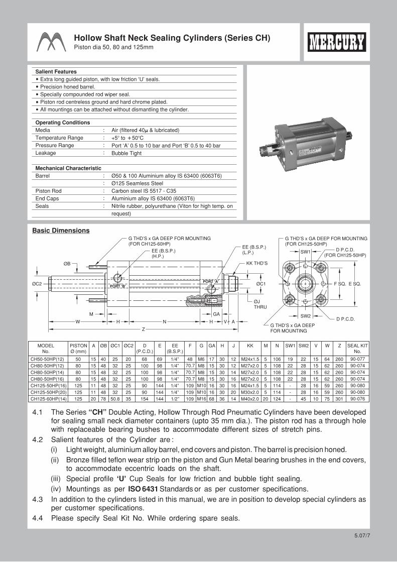
Hollow Shaft Neck Sealing Cylinders (Series CH)Piston dia 50, 80 and 125mm
Basic Dimensions
EE (B.S.P.)(L.P.)
KK THD’SØB
EE (B.S.P.)(H.P.)
G THD’S x GA DEEP FOR MOUNTING(FOR CH125-60HP)
ØC2PORT ‘B’
PORT ‘A’
ØJTHRU
ØC1
W H N H V A
GAM
Z
F SQ. E SQ.
D P.C.D.(FOR CH125-50HP)
D P.C.D.
G THD’S x GA DEEP FOR MOUNTING(FOR CH125-50HP)
G THD’S x GA DEEPFOR MOUNTING
SW2
4.1
(i)
The Series “CH” Double Acting, Hollow Through Rod Pneumatic Cylinders have been developed for sealing small neck diameter containers (upto 35 mm dia.). The piston rod has a through hole with replaceable bearing bushes to accommodate different sizes of stretch pins.
Salient features of the Cylinder are :
(ii)
Light weight, aluminium alloy barrel, end covers and piston. The barrel is precision honed.
Bronze filled teflon wear strip on the piston and Gun Metal bearing brushes in the end covers, to accommodate eccentric loads on the shaft.
Special profile ‘U’ Cup Seals for low friction and bubble tight sealing.
Mountings as per ISO 6431 Standards or as per customer specifications.
In addition to the cylinders listed in this manual, we are in position to develop special cylinders as per customer specifications.
Please specify Seal Kit No. While ordering spare seals.
(iii)
(iv)
SW1
4.2
4.3
4.4
5.07/7
MODELNo.
CH50-50HP(12)
CH80-50HP(12)
CH80-50HP(14)
CH80-50HP(16)
CH125-50HP(16)
CH125-50HP(20)
CH125-60HP(14)
PISTONØ (mm)
50
80
80
80
125
125
125
A
15
15
15
15
11
11
20
ØB
40
48
48
48
48
48
78
ØC1
25
32
32
32
32
32
50.8
ØC2
20
25
25
25
25
25
35
D(P.C.D.)
68
100
100
100
90
90
154
E
69
98
98
98
144
144
144
EE(B.S.P.)
1/4”
1/4”
1/4”
1/4”
1/4”
1/4”
1/2”
F
48
70.7
70.7
70.7
109
109
109
G
M6
M8
M8
M8
M10
M10
M16
GA
17
15
15
15
16
16
68
H
30
30
30
30
30
30
36
J
12
12
14
16
16
20
14
KK
M24x1.5
M27x2.0
M27x2.0
M27x2.0
M24x1.5
M30x2.0
M40x2.0
M
5
5
5
5
5
5
20
N
106
108
108
108
114
114
124
SW1
19
22
22
22
-
-
-
SW2
22
28
28
28
28
28
45
V
15
15
15
15
16
16
10
W
64
62
62
62
59
59
75
Z
260
260
260
260
260
260
301
SEAL KITNo.
90-077
90-074
90-074
90-074
90-080
90-080
90-076
Extra long guided piston, with low friction ‘U’ seals and unbreakable rubber magnet
for reed switch actuation.
International standard ‘T’ slots for reed switch.
Precision honed barrel.
Fine control cushion screw with lock at rear end, to prevent accidental removal.
Specially compounded rod wiper seal.
Piston rod centreless ground and hard chrome plated.
All mountings can be attached without dismantling the cylinder.
Aluminium alloy IS 63400 (6063T6)
Carbon steel IS 5517 - C35
Aluminium alloy IS 63400 (6063T6)
:
:
:
:
Mechanical Characteristic
Barrel
Piston Rod
End Caps
Seals
Salient Features
Air (filtered 40F & lubricated)
+5B to 50 C
0.5 to 10 bar
Bubble Tight
F B
:
:
:
:
Operating Conditions
Media
Temperature Range
Pressure Range
Leakage
F
F
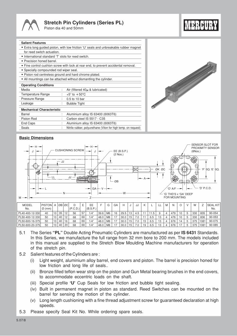
Stretch Pin Cylinders (Series PL)Piston dia 40 and 50mm
Basic Dimensions
5.1
(i)
The Series “PL” Double Acting Pneumatic Cylinders are manufactured as per IS 6431 Standards. In this Series, we manufacture the full range from 32 mm bore to 200 mm. The models included in this manual are supplied to the Stretch Blow Moulding Machine manufacturers for operation of the stretch pin.
Salient features of the Cylinders are :
(ii)
Light weight, aluminium alloy barrel, end covers and piston. The barrel is precision honed for low friction and long life of seals..
Bronze filled teflon wear strip on the piston and Gun Metal bearing brushes in the end covers, to accommodate eccentric loads on the shaft.
Special profile ‘U’ Cup Seals for low friction and bubble tight sealing.
Built in permanent magnet in piston as standard. Reed Switches can be mounted on the barrel for sensing the motion of the cylinder.
Long length cushioning with a fine thread adjustment screw for guaranteed declaration at high speeds.
Please specify Seal Kit No. While ordering spare seals.
(iii)
(iv)
5.2
(v)
5.3
EE (B.S.P.)(2 Nos.)
CUSHIONING SCREW
H
J
L
M Z
N W
VGA
ØB
H
J
JJ
LL JJ A
ØK ØC
SENSOR SLOT FORPROXIMITY SENSOR(8Nos.)
‘D’ P.C.D.‘O’ A/F
‘F’ SQ. ‘E’ SQ.
‘G’ THD’S x ‘GA’ DEEPFOR MOUNTING
Nitrile rubber, polyurethane (Viton for high temp. on request)
5.07/8
MODELNo.
PL40-400-12-330
PL50-400-12-330
PL50-600-16-375
PL50-600-20-375
PISTONØ (mm)
40
50
50
50
A
10
10
10
10
ØB
35
40
40
40
ØC
12
12
16
20
D(P.C.D.)
56
68
68
68
E
57
69
69
69
EE(B.S.P.)
1/4”
1/4”
1/4”
1/4”
F
39.6
48.0
48.0
48.0
G
M6
M8
M8
M8
GA
16
17
H
29.5
30.0
30.0
30.0
J
13
15
15
15
M
4
4
4
4
N
479
476
676
676
V
5
5
5
5
W
330
330
375
375
Z
835
836
1081
1081
17
17
JJ
4.5
7.0
7.0
7.0
K
11
11
15
19
L
11.5
6.5
6.5
6.5
O
10
10
14
17
LL
9
13
13
13
SEAL KITNo.
90-054
90-053
90-075
90-085
Valves for “Pet Moulding”
6.0
5.07/9
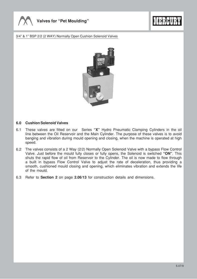
6.2
6.3
6.1
3/4” & 1” BSP 2/2 (2 WAY) Normally Open Cushion Solenoid Valves
2.06/13
7.1
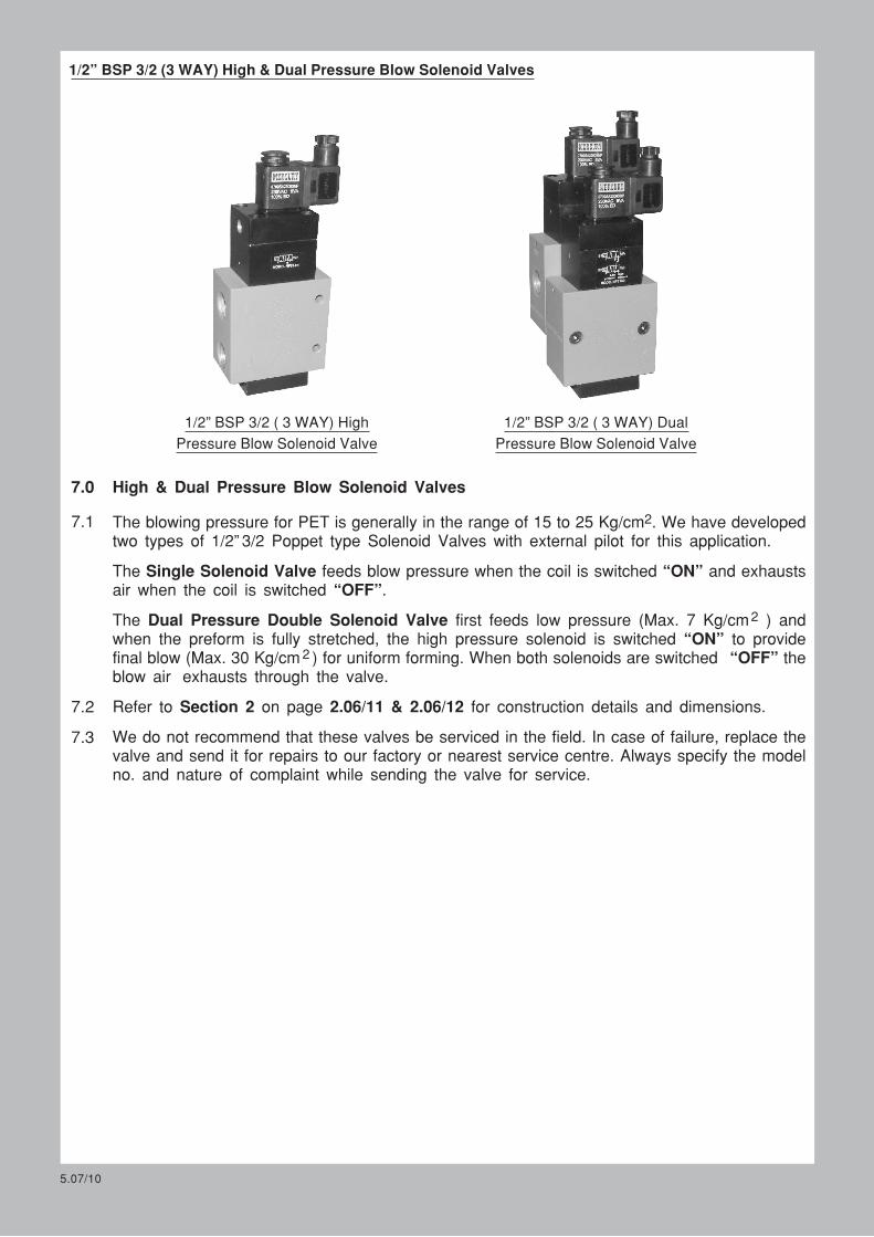
High & Dual Pressure Blow Solenoid Valves
2The blowing pressure for PET is generally in the range of 15 to 25 Kg/cm . We have developed two types of 1/2” 3/2 Poppet type Solenoid Valves with external pilot for this application.
The Single Solenoid Valve feeds blow pressure when the coil is switched “ON” and exhausts air when the coil is switched “OFF”.
The Dual Pressure Double Solenoid Valve first feeds low pressure (Max. 7 Kg/cm ) and when the preform is fully stretched, the high pressure solenoid is switched “ON” to provide final blow (Max. 30 Kg/cm ) for uniform forming. When both solenoids are switched “OFF” the blow air exhausts through the valve.
Refer to Section 2 on page 2.06/11 & 2.06/12 for construction details and dimensions.
We do not recommend that these valves be serviced in the field. In case of failure, replace the valve and send it for repairs to our factory or nearest service centre. Always specify the model no. and nature of complaint while sending the valve for service.
5.07/10
7.2
7.3
2
2
1/2” BSP 3/2 ( 3 WAY) High
Pressure Blow Solenoid Valve
1/2” BSP 3/2 ( 3 WAY) Dual
Pressure Blow Solenoid Valve
7.0
1/2” BSP 3/2 (3 WAY) High & Dual Pressure Blow Solenoid Valves
5.07/11
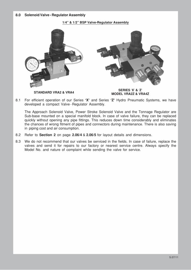
8.2
8.3
8.1
1/4” & 1/2” BSP Valve-Regulator Assembly
8.0
STANDARD VRA2 & VRA4SERIES ‘X’ & ‘Z’
MODEL VRA2Z & VRA4Z
2.06/4 & 2.06/5
piping cost and air consumption.
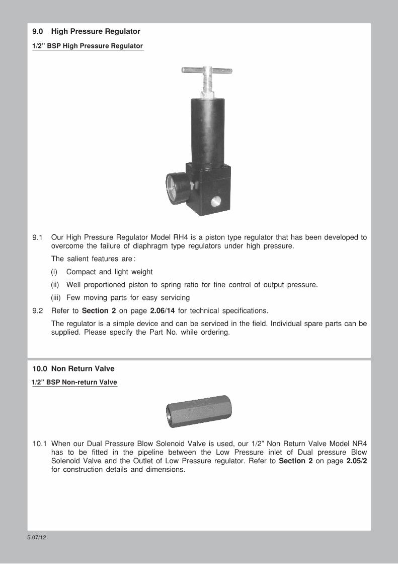
Our High Pressure Regulator Model RH4 is a piston type regulator that has been developed to overcome the failure of diaphragm type regulators under high pressure.
The salient features are :
9.2 Refer to Section 2 on page 2.06/14 for technical specifications.
The regulator is a simple device and can be serviced in the field. Individual spare parts can be supplied. Please specify the Part No. while ordering.
(i)
(ii)
Compact and light weight
Well proportioned piston to spring ratio for fine control of output pressure.
Few moving parts for easy servicing(iii)
1/2” BSP High Pressure Regulator
9.1
10.1 When our Dual Pressure Blow Solenoid Valve is used, our 1/2” Non Return Valve Model NR4 has to be fitted in the pipeline between the Low Pressure inlet of Dual pressure Blow Solenoid Valve and the Outlet of Low Pressure regulator. Refer to Section 2 on page 2.05/2 for construction details and dimensions.
1/2” BSP Non-return Valve
5.07/12
9.0 High Pressure Regulator
10.0 Non Return Valve