Hydraulic torque on the guide vane within the slight ...
11
IOP Conference Series: Earth and Environmental Science OPEN ACCESS Hydraulic torque on the guide vane within the slight opening of pump turbine in turbine operating mode To cite this article: H G Fan et al 2014 IOP Conf. Ser.: Earth Environ. Sci. 22 032050 View the article online for updates and enhancements. You may also like CFD methodology for desynchronized guide vane torque prediction and validation with experimental data T C Vu, C Devals, J Disciullo et al. - CFD Investigation of Complex Phenomena in S-Shape Region of Reversible Pump- Turbine C Jacquet, R Fortes-Patella, L Balarac et al. - Evolutions of guide vane moment of a pump-turbine during runaway transient process after pump trip Z Y Yang, Y G Cheng, L S Xia et al. - Recent citations Investigation methods for analysis of transient phenomena concerning design and operation of hydraulic-machine systems—A review Deyou Li et al - This content was downloaded from IP address 65.21.228.167 on 29/10/2021 at 10:37
Transcript of Hydraulic torque on the guide vane within the slight ...

IOP Conference Series Earth and Environmental Science
OPEN ACCESS
Hydraulic torque on the guide vane within theslight opening of pump turbine in turbine operatingmodeTo cite this article H G Fan et al 2014 IOP Conf Ser Earth Environ Sci 22 032050
View the article online for updates and enhancements
You may also likeCFD methodology for desynchronizedguide vane torque prediction andvalidation with experimental dataT C Vu C Devals J Disciullo et al
-
CFD Investigation of Complex Phenomenain S-Shape Region of Reversible Pump-TurbineC Jacquet R Fortes-Patella L Balarac etal
-
Evolutions of guide vane moment of apump-turbine during runaway transientprocess after pump tripZ Y Yang Y G Cheng L S Xia et al
-
Recent citationsInvestigation methods for analysis oftransient phenomena concerning designand operation of hydraulic-machinesystemsmdashA reviewDeyou Li et al
-
This content was downloaded from IP address 6521228167 on 29102021 at 1037
Hydraulic torque on the guide vane within the slight opening
of pump turbine in turbine operating mode
H G Fan H X Yang F C Li and N X Chen
State Key Laboratory of Hydroscience and Engineering Department of Thermal
Engineering Tsinghua University Beijing China
E-mail fanhgtsinghuaeducn Abstract In a pumped storage power station the units produce vibration and noise at times
when the guide vanes rotate into the slight opening region during the turbine operating mode
According to this phenomenon the simulation of transient flow in the units during the motion of
the guide vane is carried out to investigate the variation of flow state in the process of startup
and shutdown in turbine mode The changing rate of hydraulic torque on a single guide vane is
introduced to quantitatively represent the varying acuteness of the flow in the guide vanes and
the possibility of the noise induced by the instable flow The correlation between the frequency
of noise and water head is summarized The research indicates that the repeating reversal of fluid
after load rejection is the hydraulic phenomenon which is the cause of the distributor vibration
and noises within the slight opening which is in accordance with the data recorded during the
operation of the station The effect of guide vanes closing law on the flow state in guide vanes
and hydraulic torque on a single guide vane is analyzed
1 Introduction
In Tianhuangping pumped storage power
station vibration and loud scrape produced
by the units has occurred many times with
friction assembly alarm of the guide vanes
when the guide vanes rotate into the slight
opening region (less than 20 of the
maximum opening (33deg)) in the process of
shutdown in turbine operating mode since the
power plant generated electricity and the noise always lasts several seconds Although the plant has
taken many emergency measures the vibration frequently occurred and the reason hasnrsquot been found
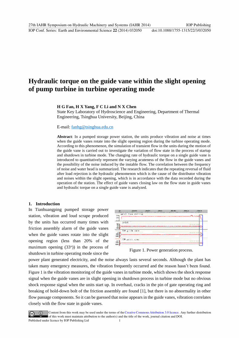
Figure 1 is the vibration monitoring of the guide vanes in turbine mode which shows the shock response
signal when the guide vanes are in slight opening in shutdown process in turbine mode but no obvious
shock response signal when the units start up In overhaul cracks in the pin of gate operating ring and
breaking of hold-down bolt of the friction assembly are found [1] but there is no abnormality in other
flow passage components So it can be guessed that noise appears in the guide vanes vibration correlates
closely with the flow state in guide vanes
Figure 1 Power generation process
27th IAHR Symposium on Hydraulic Machinery and Systems (IAHR 2014) IOP PublishingIOP Conf Series Earth and Environmental Science 22 (2014) 032050 doi1010881755-1315223032050
Content from this work may be used under the terms of the Creative Commons Attribution 30 licence Any further distributionof this work must maintain attribution to the author(s) and the title of the work journal citation and DOI
Published under licence by IOP Publishing Ltd 1
Many numerical simulations of the hydraulic machine in steady operation have been carried out The
simulation for the transition such as startup and shutdown is still at developing stage and some
researchers have made preliminarily studies Haifa [2] has made three dimension simulation of the
transient performance in micro-pump when the screw is rotating and the effect of screw threat pitch
Reynolds number and pump load on dynamic flow property were studied Wang [3] has made simulation
of a two dimensional centrifugal pump with the Large Eddy Simulation (LES) during its starting period
and obtained the velocity and pressure distribution in different time Comparison between transient
computation results and that of quasi-steady hypothesis indicates the transient effect of the flow during
starting period Wu [4] has made three dimensional simulation of the unsteady flow in a centrifugal
pump with whole circulation pipeline during starting period The unsteady flow evolution in the pump
was analyzed and its transient hydraulic characteristics was predicted The numerical results
qualitatively agreed with the test results Using RNG k-ε turbulence model Zhou [5] obtained the
variation of the model unitrsquos moment axial hydro-thrust rotational speed and mass flow rate by
simulation of the load-rejection transient of the Kaplan turbine under the rated head and the largest head
condition with rated output the runaway speed computation result and the test one error was less than
2 Li [6] analyzed the unsteady flow and pressure fluctuation by a 3D unsteady turbulent simulation
of the load-rejection transient of the Francis turbine with RNG k-ε turbulence model the computation
result of runner speed and pressure in the inlet of draft tube agrees with the test one but the calculated
pressure in the inlet of spiral casing was different with the test one without the consideration of water
hammer in the penstock Kolsek [7] has made three dimensional simulation of unsteady flow during
shut-down process of an axial water turbine Rotation speed axial force and pressure at the point which
located between distributor and runner were analyzed and the results agree with the prototype
measurement data Benigni [8] obtained the velocity distribution around the runner for different
operating points and found the separation zones near the wall of the draft tube by transient simulation
with SST-model of Menter
In summary the simulation of flow state in guide vanes when they are rotating into slight opening is
not deep Unsteady numerical study of dynamic process is still in its infancy The reason why the units
produce abnormal vibration and make noise is not clear and doesnrsquot reach a consensus Therefore to
ensure the safety and stability of the unitsrsquo long-term operation it is necessary to study the unitsrsquo stability
in slight opening deeply reveal the cause of vibration and put forward effective control schemes to avoid
the vibration
In order to reveal the hydraulic reason inducing the vibration of distributor this paper studied the
dynamic flow characteristic in guide vanes with numerical simulation method The correlation between
noise frequency and water level of upper reservoir and down reservoir is analyzed and the simulation
results and the plant operation statistics are compared
2 Numerical simulation method
RNG k~ε two equation model [9][10] is selected to simulate the flow in the pump turbine in the paper
because it can simulate the flow separation and vortex and is more accurate in the near wall areas
Equation (1) and equation (2) are the equations of RNG k~ε model
27th IAHR Symposium on Hydraulic Machinery and Systems (IAHR 2014) IOP PublishingIOP Conf Series Earth and Environmental Science 22 (2014) 032050 doi1010881755-1315223032050
2
( ) ( ) ( )i k eff k b M
i j j
kk ku G G Y
t x x x
(1)
2
1 3 2( ) ( ) ( ) ( )i eff k b
i j j
u G G C G C Rt x x x k k
(2)
Where i and j are direction of axis x is axis u is absolute velocity t is time is density kG is the
generation of turbulence kinetic energy due to the mean velocity gradients bG is the generation of
turbulence kinetic energy due to buoyancy MY is the contribution of the fluctuating dilatation in
compressible turbulence to the overall dissipation rate the quantities α120576 and α119896 are the inverse
effective Prandtl numbers for ε and k respectively
3 Computational domain
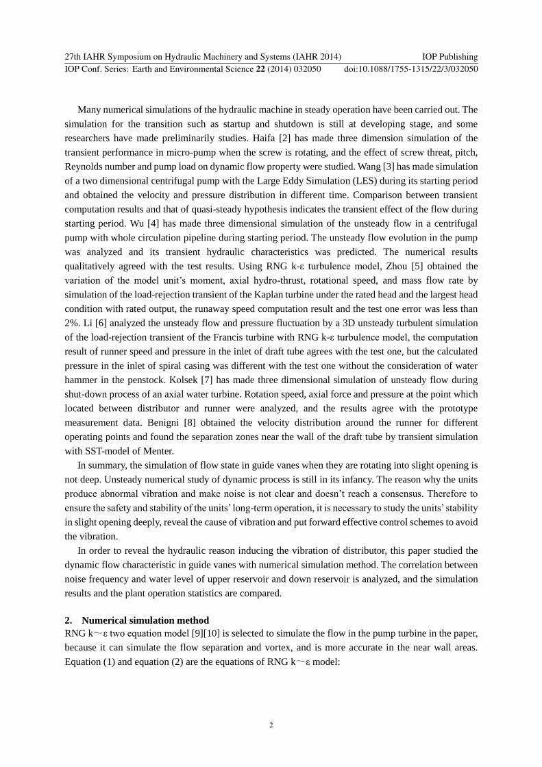
In pump turbine the distributor height is small and the flow is 2 dimensional and periodic The influence
of finite number of guide vanes can be neglected A two dimensional model is set up in order to rational
use the limited computation resource The domain is shown in Figure 2 includes a guide vane and a
channel between two stay vanes which extends to upstream and downstream
Figure 2 Computation
domain
Figure 3 Boundary conditions Figure 4 Mesh between the guide
vanes
In turbine mode it flows from fix vanes to guide vanes so a velocity is imposed on the boundary
near the fix vane According to the fundamental equation of the hydraulic machine the radial component
of the velocity in the inlet of the computation domain can be calculated by equation (3) where flux Q(t)
can be calculated by the transient simulation of the power station
( )( )r
Q tV t
A (3)
The tangential component can be set by the condition that there is no shock in the inlet of stay vane
A constant static pressure is set on the side near the guide vane because the relative pressure amplitude
is small Guide vane and stay vane is set as no slip wall Periodic boundary conditions are used at both
sides of the single periodic channel Boundary condition can be shown in Figure 3
It is necessary to open or close guide vanes according to some law in the transient process of pump
turbine such as startup shutdown and operation switch In the transient simulation of the flow in the
pump turbine meshes around the vanes should be adjusted with the movement of the guide vanes
Considering that the guide vanes are set as the moving boundary Spring-based smoothing and local
remeshing [11] are used to realize the adjustment of the meshes around the guide vanes in the transient
process
In the slight opening the gap is much less than the characteristic length of the passage such as vane
length Boundary-fitted quadrilateral mesh is used around the guide vane and triangle mesh is used in
27th IAHR Symposium on Hydraulic Machinery and Systems (IAHR 2014) IOP PublishingIOP Conf Series Earth and Environmental Science 22 (2014) 032050 doi1010881755-1315223032050
3
other area which is shown in Figure 4
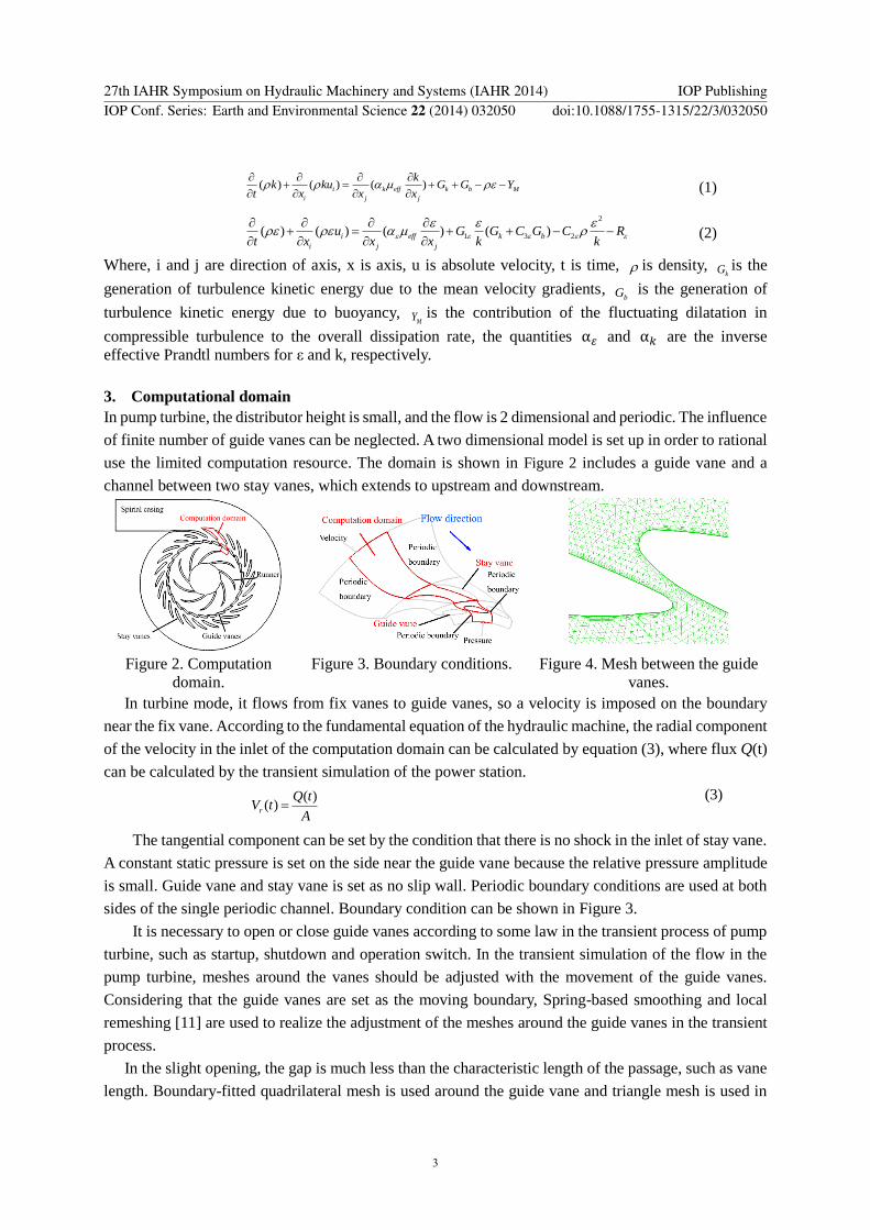
The steady numerical simulation is performed in different guide vane opening angles The number
of elements is compared ranging from 5000 to 300000 Figure 5 indicates that the hydraulic torque in a
guide vane is independent of element number when it is larger than 50000 In this paper the domain
involving single channel is meshed with 50000 elements
Startup and shutdown process in pumping mode is simulated in different time steps ranging from
001s to 000025s the hydraulic torque amplitude varies to time step is shown in Figure 6 which
indicates that the hydraulic torque amplitude is independent of time step when it is less than 0001s The
time step of the transient simulation in guide vanes is set as 0001s
Figure 5 Different mesh numbers Figure 6 Different time steps
4 Results and analysis
41 Startup process simulation in turbine mode
Figure 7 shows the flux of the unit in different heads when the guide vanes are opening which is
calculated by the transient simulation of the power plant Figure 8 shows the hydraulic torque of the
guide vane which is opening with the 25s slope The figures show that hydraulic torque changes gently
and no sudden change happened when guide vanes rotate into the slight opening
Figure 7 Discharge of the unit Figure 8 Hydraulic torque on the guide vane
Figure 9 shows the streamlines and the pressure distribution in different opening angles when the
guide vanes are opening in the turbine mode and the head is 610m In the process of opening flow in
guide vanes maintain the same flow pattern and static pressure changes gently which is not easy to
induce the vibration of the distributor The result is consistent with the fact that there is no noise in the
startup process of turbine mode in the power plant
27th IAHR Symposium on Hydraulic Machinery and Systems (IAHR 2014) IOP PublishingIOP Conf Series Earth and Environmental Science 22 (2014) 032050 doi1010881755-1315223032050
4
Velocity
(ms)
Pressure
(Pa)
(a)Guide vane opening is 1deg (b) Guide vane opening is 2deg (c) Guide vane opening is 3deg
Figure 9 Transient flow when the guide vane is opening in head 610m
42 Shutdown process simulation in turbine mode
When the units shut down the runner speeds up in the
direction of turbine mode with the closing of guide vanes
As shown in Figure 10 closing law (2) has a different
inflection point with law (1) while the second segment of
law (2) has the same slope with law (1)
Figure 11 shows the flux of the unit in different heads
when the guide vanes are closing which is calculated by
the transient simulation of the power plant Adopting
closing law (1) the discharge of unit fluctuates near 0 in
slight opening of guide vanes when the head is less than 570m which means that the direction of the
flow changes frequently and while the head is above 570m it keeps negative The flux of units adopting
closing law (2) fluctuates near 0 within the whole operating head
(a) Closing law (1) (b) Closing law (2)
Figure 11 Discharge of the unit
Figure 10 Closing laws of guide vanes
27th IAHR Symposium on Hydraulic Machinery and Systems (IAHR 2014) IOP PublishingIOP Conf Series Earth and Environmental Science 22 (2014) 032050 doi1010881755-1315223032050
5
Figure 12 shows the hydraulic torque in a guide vane which is closing As shown in Figure 13 the
time from the maximum hydraulic torque to the minimum is defined as the transition time the max
change of the torque of the guide vane is defined as the torque amplitude and the ratio of the torque
amplitude to transition time is defined as the torque change rate which indicates the average change of
the torque Figure 14 shows the correlation between hydraulic torque changing rate and head The
changing rate of torque is large in low head by using closing law (1) which indicate that flow pattern in
guide vanes changes intensely By using closing law (2) the maximum value of torque change rate
appears when the head is about 550m When the head is above 550m torque change rate of the units
adopting law (2) is significantly greater than the units adopting closing law (1)
(a) Closing law (1) (b) Closing law (2)
Figure 12 Hydraulic torque of the guide vane
Figure 13 Hydraulic torque changing rate Figure 14 Hydraulic torque changing rate in
different heads
Figure 15 shows the streamlines and the pressure distribution in different opening angles of unit
adopting closing law (1) when the guide vanes are closed in the turbine mode and the head is 526m The
flow pattern in the guide vanes changes noticeably because of the repeating reversal flow The
streamlines and the pressure distribution in different opening angles of unit adopting closing law (1)
when the guide vanes are closing in the turbine mode and the head is 610m are shown in Figure 16 The
direction of flow in guide vanes keeps negative and the flow pattern changes smoothly Therefore the
torque change rate is smaller than it at low head
The simulation results indicate that the repeating reversal flow is the main performance of the change
of flow state in guide vanes after load rejection Although the absolute value and change rate is tiny
relative change rate of flux is large when the guide vanes are in slight opening The flux of units adopting
closing law (1) for example fluctuates around 0 at low water head and keeps negative at high head At
low head the relative change rate of flux is much greater than at high head resulting that the torque
change rate is greater
27th IAHR Symposium on Hydraulic Machinery and Systems (IAHR 2014) IOP PublishingIOP Conf Series Earth and Environmental Science 22 (2014) 032050 doi1010881755-1315223032050
6
Velocity
(ms)
Pressure
(Pa)
(a)Guide vane opening is 6deg (b)Guide vane opening is 52deg (c)Guide vane opening is 44deg
Velocity
(ms)
Figure 15 Transient flow
when the guide vane is
closing with law (1) in
head 526m
Pressure
(Pa)
(d)Guide vane opening is 36deg (e)Guide vane opening is 28deg
27th IAHR Symposium on Hydraulic Machinery and Systems (IAHR 2014) IOP PublishingIOP Conf Series Earth and Environmental Science 22 (2014) 032050 doi1010881755-1315223032050
7
Velocity
(ms)
Pressure
(Pa)
(a)Guide vane opening is 5deg (b)Guide vane opening is 34deg (c) Guide vane opening is 18deg
Figure 16 Transient flow when the guide vane is closing with law (1) in head 610m
The water levels of reservoirs recorded when the loud scrape occurs is converted into the operation
head which is called the noise head Figure 17 shows the noise head
distribution when the loud scrape occurs in the shutdown process
using two guide vane closing laws which indicate that noise head
mainly concentrates at the head ranging from 530m to 550m
Comparison of simulation results and plant operation statistics is
shown in Figure 18 and Figure 19 The calculation predict accurately
that the possibility of making noise at low head is greater At high
head conditions units adopting closing law (2) are more likely to
make noises which coincides with the statistic data
Figure 18 Distribution ratio of noise head
(closing law (1))
Figure 19 Distribution ratio of noise head
(closing law (2))
43 Comparison of different guide vanes closing laws
Repeating reversal flow is the cause of the vibration in the sight opening guide vanes when the units
Figure 17 Scattered distribution of noise
head
27th IAHR Symposium on Hydraulic Machinery and Systems (IAHR 2014) IOP PublishingIOP Conf Series Earth and Environmental Science 22 (2014) 032050 doi1010881755-1315223032050
8
shut down In order to restrain the flux fluctuation around 0 different closing laws are analyzed Figure
20 shows the closing laws which have different slope at second segment
Figure 20 Closing laws Figure 21 Discharge of the unit
Figure 21 shows the flux of the unit using different closing laws which is calculated by the transient
simulation of the power plant As can be seen with the acceleration of second segment of the closing
law unit flux increases in reversal direction moves away from 0 gradually
Figure 22 shows the hydraulic torque of a guide vane varies with the closing law Figure 23 shows
the relation between change rate of torque and the slope of second segment of closing law which
indicates that accelerating the closing speed of second segment appropriately can reduce the change rate
of torque of guide vane However with the acceleration of closing speed the maximum pressure of
spiral case inlet and minimum pressure of draft tube inlet are deteriorated which have a negative
influence to the safe operation of the diversion system as shown in Figure 23 (the reference value is the
pressure when the slope of second segment is 25s)
Figure 22 Hydraulic torque of the guide vane Figure 23 Hydraulic torque changing rate of
different closing speed
5 Conclusion
Simulation of the transient flow in the guide vanes indicates the repeating reversal of fluid occurs when
the guide vanes rotate into the slight opening during the shutdown process in turbine mode which results
in the sudden change of the torque When the torque made by the servomotor canrsquot adapt the abrupt
change quickly the vibration and loud scrape maybe occur The larger torque change rate the more
possibility of the vibration and scrape The calculation result is basically in agreement with the statistical
data of the power station
In the end the effect of different closing laws is studied when guide vanes rotate in slight opening
which indicates that accelerating the closing speed appropriately can reduce the reversal flow in guide
27th IAHR Symposium on Hydraulic Machinery and Systems (IAHR 2014) IOP PublishingIOP Conf Series Earth and Environmental Science 22 (2014) 032050 doi1010881755-1315223032050
9
vanes and improve the stability of flow state in guide vanes but the maximum pressure of spiral case
inlet and minimum pressure of draft tube inlet are deteriorated
6 Acknowledgments
The authors would like to thank National Natural Science Foundation of China (No 51279084) and
State Key Laboratory of Hydro Science amp Hydraulic Engineering (2014-KY-05) for their financial
support
Nomenclature
V = absolute velocity
r = radial coordinate
θ = tangential coordinate
t = time
Q = discharge
p = static pressure
= density
= viscosity coefficient
g = gravity acceleration
rA = area
References [1] Kong L H 2004 Exceptional sound in operation switch of high head pump turbine Mechanical and
electrical technology in hydraulic power station (6) 12-14
[2] Ei Sadi H and Esmail N 2006 Simulation of three-dimensional transient performance in micro-pump
Sensors and Actuators (115) 510-518
[3] Wang L Q Li Z F Dai W P and Wu D Z 2008 2-D numerical simulation on transient flow in centrifugal
pump during starting period Journal of engineering thermophysics 29(8) 1319-1322
[4] Wu D Z Xu B J Li Z F and Wang L Q 2009 Numerical simulation on internal flow of centrifugal
pump during transient operation Journal of engineering thermophysics 30(5) 781-783
[5] Zhou D Q Wu Y L and Liu S H 2010 Three-dimensional CFD simulation of the runaway transients
of a propeller turbine model Journal of hydraulic engineering 41(2) 233-238
[6] Li J Yu J and Wu Y 2010 3D unsteady turbulent simulations of transients of the Francis turbine 25th
IAHR Sym on Hydraulic Machinery and Systems (Timisoara Romania)
[7] Kolsek T Duhovnik J and Bergant A 2006 Simulation of unsteady flow and runner rotation during
shut-down of an axial water turbine Journal of Hydraulic Research 44(1) 129-137
[8] Benigni H and Jaberg H 2007 Stationary and transient numerical simulation of a bulb turbine Proc of
the 5th IASMEWSEAS Int Conf on Fluid Mechanics and Aerodynamics (Athens Greece)
[9] Mompean M 1998 Numerical simulation of a turbulent flow near a right-angled corner using the
special non-linear model with RNG k-ε equations Computers amp Fluids 27(7) 847-859
[10] Wang Z W and Zhou L J 2006 Simulation and Measurements of pressure oscillations caused by vortex
ropes Journal of Fluid Engineering 128(6) 649-655
[11] Huang S Yang F X Guo J and Ou G W 2013 Numerical Simulation of 3D Unsteady Flow in
Centrifugal Pump by Dynamic Mesh Technique Science amp Technology Review 31(24) 33-36
27th IAHR Symposium on Hydraulic Machinery and Systems (IAHR 2014) IOP PublishingIOP Conf Series Earth and Environmental Science 22 (2014) 032050 doi1010881755-1315223032050
10
Hydraulic torque on the guide vane within the slight opening
of pump turbine in turbine operating mode
H G Fan H X Yang F C Li and N X Chen
State Key Laboratory of Hydroscience and Engineering Department of Thermal
Engineering Tsinghua University Beijing China
E-mail fanhgtsinghuaeducn Abstract In a pumped storage power station the units produce vibration and noise at times
when the guide vanes rotate into the slight opening region during the turbine operating mode
According to this phenomenon the simulation of transient flow in the units during the motion of
the guide vane is carried out to investigate the variation of flow state in the process of startup
and shutdown in turbine mode The changing rate of hydraulic torque on a single guide vane is
introduced to quantitatively represent the varying acuteness of the flow in the guide vanes and
the possibility of the noise induced by the instable flow The correlation between the frequency
of noise and water head is summarized The research indicates that the repeating reversal of fluid
after load rejection is the hydraulic phenomenon which is the cause of the distributor vibration
and noises within the slight opening which is in accordance with the data recorded during the
operation of the station The effect of guide vanes closing law on the flow state in guide vanes
and hydraulic torque on a single guide vane is analyzed
1 Introduction
In Tianhuangping pumped storage power
station vibration and loud scrape produced
by the units has occurred many times with
friction assembly alarm of the guide vanes
when the guide vanes rotate into the slight
opening region (less than 20 of the
maximum opening (33deg)) in the process of
shutdown in turbine operating mode since the
power plant generated electricity and the noise always lasts several seconds Although the plant has
taken many emergency measures the vibration frequently occurred and the reason hasnrsquot been found
Figure 1 is the vibration monitoring of the guide vanes in turbine mode which shows the shock response
signal when the guide vanes are in slight opening in shutdown process in turbine mode but no obvious
shock response signal when the units start up In overhaul cracks in the pin of gate operating ring and
breaking of hold-down bolt of the friction assembly are found [1] but there is no abnormality in other
flow passage components So it can be guessed that noise appears in the guide vanes vibration correlates
closely with the flow state in guide vanes
Figure 1 Power generation process
27th IAHR Symposium on Hydraulic Machinery and Systems (IAHR 2014) IOP PublishingIOP Conf Series Earth and Environmental Science 22 (2014) 032050 doi1010881755-1315223032050
Content from this work may be used under the terms of the Creative Commons Attribution 30 licence Any further distributionof this work must maintain attribution to the author(s) and the title of the work journal citation and DOI
Published under licence by IOP Publishing Ltd 1
Many numerical simulations of the hydraulic machine in steady operation have been carried out The
simulation for the transition such as startup and shutdown is still at developing stage and some
researchers have made preliminarily studies Haifa [2] has made three dimension simulation of the
transient performance in micro-pump when the screw is rotating and the effect of screw threat pitch
Reynolds number and pump load on dynamic flow property were studied Wang [3] has made simulation
of a two dimensional centrifugal pump with the Large Eddy Simulation (LES) during its starting period
and obtained the velocity and pressure distribution in different time Comparison between transient
computation results and that of quasi-steady hypothesis indicates the transient effect of the flow during
starting period Wu [4] has made three dimensional simulation of the unsteady flow in a centrifugal
pump with whole circulation pipeline during starting period The unsteady flow evolution in the pump
was analyzed and its transient hydraulic characteristics was predicted The numerical results
qualitatively agreed with the test results Using RNG k-ε turbulence model Zhou [5] obtained the
variation of the model unitrsquos moment axial hydro-thrust rotational speed and mass flow rate by
simulation of the load-rejection transient of the Kaplan turbine under the rated head and the largest head
condition with rated output the runaway speed computation result and the test one error was less than
2 Li [6] analyzed the unsteady flow and pressure fluctuation by a 3D unsteady turbulent simulation
of the load-rejection transient of the Francis turbine with RNG k-ε turbulence model the computation
result of runner speed and pressure in the inlet of draft tube agrees with the test one but the calculated
pressure in the inlet of spiral casing was different with the test one without the consideration of water
hammer in the penstock Kolsek [7] has made three dimensional simulation of unsteady flow during
shut-down process of an axial water turbine Rotation speed axial force and pressure at the point which
located between distributor and runner were analyzed and the results agree with the prototype
measurement data Benigni [8] obtained the velocity distribution around the runner for different
operating points and found the separation zones near the wall of the draft tube by transient simulation
with SST-model of Menter
In summary the simulation of flow state in guide vanes when they are rotating into slight opening is
not deep Unsteady numerical study of dynamic process is still in its infancy The reason why the units
produce abnormal vibration and make noise is not clear and doesnrsquot reach a consensus Therefore to
ensure the safety and stability of the unitsrsquo long-term operation it is necessary to study the unitsrsquo stability
in slight opening deeply reveal the cause of vibration and put forward effective control schemes to avoid
the vibration
In order to reveal the hydraulic reason inducing the vibration of distributor this paper studied the
dynamic flow characteristic in guide vanes with numerical simulation method The correlation between
noise frequency and water level of upper reservoir and down reservoir is analyzed and the simulation
results and the plant operation statistics are compared
2 Numerical simulation method
RNG k~ε two equation model [9][10] is selected to simulate the flow in the pump turbine in the paper
because it can simulate the flow separation and vortex and is more accurate in the near wall areas
Equation (1) and equation (2) are the equations of RNG k~ε model
27th IAHR Symposium on Hydraulic Machinery and Systems (IAHR 2014) IOP PublishingIOP Conf Series Earth and Environmental Science 22 (2014) 032050 doi1010881755-1315223032050
2
( ) ( ) ( )i k eff k b M
i j j
kk ku G G Y
t x x x
(1)
2
1 3 2( ) ( ) ( ) ( )i eff k b
i j j
u G G C G C Rt x x x k k
(2)
Where i and j are direction of axis x is axis u is absolute velocity t is time is density kG is the
generation of turbulence kinetic energy due to the mean velocity gradients bG is the generation of
turbulence kinetic energy due to buoyancy MY is the contribution of the fluctuating dilatation in
compressible turbulence to the overall dissipation rate the quantities α120576 and α119896 are the inverse
effective Prandtl numbers for ε and k respectively
3 Computational domain
In pump turbine the distributor height is small and the flow is 2 dimensional and periodic The influence
of finite number of guide vanes can be neglected A two dimensional model is set up in order to rational
use the limited computation resource The domain is shown in Figure 2 includes a guide vane and a
channel between two stay vanes which extends to upstream and downstream
Figure 2 Computation
domain
Figure 3 Boundary conditions Figure 4 Mesh between the guide
vanes
In turbine mode it flows from fix vanes to guide vanes so a velocity is imposed on the boundary
near the fix vane According to the fundamental equation of the hydraulic machine the radial component
of the velocity in the inlet of the computation domain can be calculated by equation (3) where flux Q(t)
can be calculated by the transient simulation of the power station
( )( )r
Q tV t
A (3)
The tangential component can be set by the condition that there is no shock in the inlet of stay vane
A constant static pressure is set on the side near the guide vane because the relative pressure amplitude
is small Guide vane and stay vane is set as no slip wall Periodic boundary conditions are used at both
sides of the single periodic channel Boundary condition can be shown in Figure 3
It is necessary to open or close guide vanes according to some law in the transient process of pump
turbine such as startup shutdown and operation switch In the transient simulation of the flow in the
pump turbine meshes around the vanes should be adjusted with the movement of the guide vanes
Considering that the guide vanes are set as the moving boundary Spring-based smoothing and local
remeshing [11] are used to realize the adjustment of the meshes around the guide vanes in the transient
process
In the slight opening the gap is much less than the characteristic length of the passage such as vane
length Boundary-fitted quadrilateral mesh is used around the guide vane and triangle mesh is used in
27th IAHR Symposium on Hydraulic Machinery and Systems (IAHR 2014) IOP PublishingIOP Conf Series Earth and Environmental Science 22 (2014) 032050 doi1010881755-1315223032050
3
other area which is shown in Figure 4
The steady numerical simulation is performed in different guide vane opening angles The number
of elements is compared ranging from 5000 to 300000 Figure 5 indicates that the hydraulic torque in a
guide vane is independent of element number when it is larger than 50000 In this paper the domain
involving single channel is meshed with 50000 elements
Startup and shutdown process in pumping mode is simulated in different time steps ranging from
001s to 000025s the hydraulic torque amplitude varies to time step is shown in Figure 6 which
indicates that the hydraulic torque amplitude is independent of time step when it is less than 0001s The
time step of the transient simulation in guide vanes is set as 0001s
Figure 5 Different mesh numbers Figure 6 Different time steps
4 Results and analysis
41 Startup process simulation in turbine mode
Figure 7 shows the flux of the unit in different heads when the guide vanes are opening which is
calculated by the transient simulation of the power plant Figure 8 shows the hydraulic torque of the
guide vane which is opening with the 25s slope The figures show that hydraulic torque changes gently
and no sudden change happened when guide vanes rotate into the slight opening
Figure 7 Discharge of the unit Figure 8 Hydraulic torque on the guide vane
Figure 9 shows the streamlines and the pressure distribution in different opening angles when the
guide vanes are opening in the turbine mode and the head is 610m In the process of opening flow in
guide vanes maintain the same flow pattern and static pressure changes gently which is not easy to
induce the vibration of the distributor The result is consistent with the fact that there is no noise in the
startup process of turbine mode in the power plant
27th IAHR Symposium on Hydraulic Machinery and Systems (IAHR 2014) IOP PublishingIOP Conf Series Earth and Environmental Science 22 (2014) 032050 doi1010881755-1315223032050
4
Velocity
(ms)
Pressure
(Pa)
(a)Guide vane opening is 1deg (b) Guide vane opening is 2deg (c) Guide vane opening is 3deg
Figure 9 Transient flow when the guide vane is opening in head 610m
42 Shutdown process simulation in turbine mode
When the units shut down the runner speeds up in the
direction of turbine mode with the closing of guide vanes
As shown in Figure 10 closing law (2) has a different
inflection point with law (1) while the second segment of
law (2) has the same slope with law (1)
Figure 11 shows the flux of the unit in different heads
when the guide vanes are closing which is calculated by
the transient simulation of the power plant Adopting
closing law (1) the discharge of unit fluctuates near 0 in
slight opening of guide vanes when the head is less than 570m which means that the direction of the
flow changes frequently and while the head is above 570m it keeps negative The flux of units adopting
closing law (2) fluctuates near 0 within the whole operating head
(a) Closing law (1) (b) Closing law (2)
Figure 11 Discharge of the unit
Figure 10 Closing laws of guide vanes
27th IAHR Symposium on Hydraulic Machinery and Systems (IAHR 2014) IOP PublishingIOP Conf Series Earth and Environmental Science 22 (2014) 032050 doi1010881755-1315223032050
5
Figure 12 shows the hydraulic torque in a guide vane which is closing As shown in Figure 13 the
time from the maximum hydraulic torque to the minimum is defined as the transition time the max
change of the torque of the guide vane is defined as the torque amplitude and the ratio of the torque
amplitude to transition time is defined as the torque change rate which indicates the average change of
the torque Figure 14 shows the correlation between hydraulic torque changing rate and head The
changing rate of torque is large in low head by using closing law (1) which indicate that flow pattern in
guide vanes changes intensely By using closing law (2) the maximum value of torque change rate
appears when the head is about 550m When the head is above 550m torque change rate of the units
adopting law (2) is significantly greater than the units adopting closing law (1)
(a) Closing law (1) (b) Closing law (2)
Figure 12 Hydraulic torque of the guide vane
Figure 13 Hydraulic torque changing rate Figure 14 Hydraulic torque changing rate in
different heads
Figure 15 shows the streamlines and the pressure distribution in different opening angles of unit
adopting closing law (1) when the guide vanes are closed in the turbine mode and the head is 526m The
flow pattern in the guide vanes changes noticeably because of the repeating reversal flow The
streamlines and the pressure distribution in different opening angles of unit adopting closing law (1)
when the guide vanes are closing in the turbine mode and the head is 610m are shown in Figure 16 The
direction of flow in guide vanes keeps negative and the flow pattern changes smoothly Therefore the
torque change rate is smaller than it at low head
The simulation results indicate that the repeating reversal flow is the main performance of the change
of flow state in guide vanes after load rejection Although the absolute value and change rate is tiny
relative change rate of flux is large when the guide vanes are in slight opening The flux of units adopting
closing law (1) for example fluctuates around 0 at low water head and keeps negative at high head At
low head the relative change rate of flux is much greater than at high head resulting that the torque
change rate is greater
27th IAHR Symposium on Hydraulic Machinery and Systems (IAHR 2014) IOP PublishingIOP Conf Series Earth and Environmental Science 22 (2014) 032050 doi1010881755-1315223032050
6
Velocity
(ms)
Pressure
(Pa)
(a)Guide vane opening is 6deg (b)Guide vane opening is 52deg (c)Guide vane opening is 44deg
Velocity
(ms)
Figure 15 Transient flow
when the guide vane is
closing with law (1) in
head 526m
Pressure
(Pa)
(d)Guide vane opening is 36deg (e)Guide vane opening is 28deg
27th IAHR Symposium on Hydraulic Machinery and Systems (IAHR 2014) IOP PublishingIOP Conf Series Earth and Environmental Science 22 (2014) 032050 doi1010881755-1315223032050
7
Velocity
(ms)
Pressure
(Pa)
(a)Guide vane opening is 5deg (b)Guide vane opening is 34deg (c) Guide vane opening is 18deg
Figure 16 Transient flow when the guide vane is closing with law (1) in head 610m
The water levels of reservoirs recorded when the loud scrape occurs is converted into the operation
head which is called the noise head Figure 17 shows the noise head
distribution when the loud scrape occurs in the shutdown process
using two guide vane closing laws which indicate that noise head
mainly concentrates at the head ranging from 530m to 550m
Comparison of simulation results and plant operation statistics is
shown in Figure 18 and Figure 19 The calculation predict accurately
that the possibility of making noise at low head is greater At high
head conditions units adopting closing law (2) are more likely to
make noises which coincides with the statistic data
Figure 18 Distribution ratio of noise head
(closing law (1))
Figure 19 Distribution ratio of noise head
(closing law (2))
43 Comparison of different guide vanes closing laws
Repeating reversal flow is the cause of the vibration in the sight opening guide vanes when the units
Figure 17 Scattered distribution of noise
head
27th IAHR Symposium on Hydraulic Machinery and Systems (IAHR 2014) IOP PublishingIOP Conf Series Earth and Environmental Science 22 (2014) 032050 doi1010881755-1315223032050
8
shut down In order to restrain the flux fluctuation around 0 different closing laws are analyzed Figure
20 shows the closing laws which have different slope at second segment
Figure 20 Closing laws Figure 21 Discharge of the unit
Figure 21 shows the flux of the unit using different closing laws which is calculated by the transient
simulation of the power plant As can be seen with the acceleration of second segment of the closing
law unit flux increases in reversal direction moves away from 0 gradually
Figure 22 shows the hydraulic torque of a guide vane varies with the closing law Figure 23 shows
the relation between change rate of torque and the slope of second segment of closing law which
indicates that accelerating the closing speed of second segment appropriately can reduce the change rate
of torque of guide vane However with the acceleration of closing speed the maximum pressure of
spiral case inlet and minimum pressure of draft tube inlet are deteriorated which have a negative
influence to the safe operation of the diversion system as shown in Figure 23 (the reference value is the
pressure when the slope of second segment is 25s)
Figure 22 Hydraulic torque of the guide vane Figure 23 Hydraulic torque changing rate of
different closing speed
5 Conclusion
Simulation of the transient flow in the guide vanes indicates the repeating reversal of fluid occurs when
the guide vanes rotate into the slight opening during the shutdown process in turbine mode which results
in the sudden change of the torque When the torque made by the servomotor canrsquot adapt the abrupt
change quickly the vibration and loud scrape maybe occur The larger torque change rate the more
possibility of the vibration and scrape The calculation result is basically in agreement with the statistical
data of the power station
In the end the effect of different closing laws is studied when guide vanes rotate in slight opening
which indicates that accelerating the closing speed appropriately can reduce the reversal flow in guide
27th IAHR Symposium on Hydraulic Machinery and Systems (IAHR 2014) IOP PublishingIOP Conf Series Earth and Environmental Science 22 (2014) 032050 doi1010881755-1315223032050
9
vanes and improve the stability of flow state in guide vanes but the maximum pressure of spiral case
inlet and minimum pressure of draft tube inlet are deteriorated
6 Acknowledgments
The authors would like to thank National Natural Science Foundation of China (No 51279084) and
State Key Laboratory of Hydro Science amp Hydraulic Engineering (2014-KY-05) for their financial
support
Nomenclature
V = absolute velocity
r = radial coordinate
θ = tangential coordinate
t = time
Q = discharge
p = static pressure
= density
= viscosity coefficient
g = gravity acceleration
rA = area
References [1] Kong L H 2004 Exceptional sound in operation switch of high head pump turbine Mechanical and
electrical technology in hydraulic power station (6) 12-14
[2] Ei Sadi H and Esmail N 2006 Simulation of three-dimensional transient performance in micro-pump
Sensors and Actuators (115) 510-518
[3] Wang L Q Li Z F Dai W P and Wu D Z 2008 2-D numerical simulation on transient flow in centrifugal
pump during starting period Journal of engineering thermophysics 29(8) 1319-1322
[4] Wu D Z Xu B J Li Z F and Wang L Q 2009 Numerical simulation on internal flow of centrifugal
pump during transient operation Journal of engineering thermophysics 30(5) 781-783
[5] Zhou D Q Wu Y L and Liu S H 2010 Three-dimensional CFD simulation of the runaway transients
of a propeller turbine model Journal of hydraulic engineering 41(2) 233-238
[6] Li J Yu J and Wu Y 2010 3D unsteady turbulent simulations of transients of the Francis turbine 25th
IAHR Sym on Hydraulic Machinery and Systems (Timisoara Romania)
[7] Kolsek T Duhovnik J and Bergant A 2006 Simulation of unsteady flow and runner rotation during
shut-down of an axial water turbine Journal of Hydraulic Research 44(1) 129-137
[8] Benigni H and Jaberg H 2007 Stationary and transient numerical simulation of a bulb turbine Proc of
the 5th IASMEWSEAS Int Conf on Fluid Mechanics and Aerodynamics (Athens Greece)
[9] Mompean M 1998 Numerical simulation of a turbulent flow near a right-angled corner using the
special non-linear model with RNG k-ε equations Computers amp Fluids 27(7) 847-859
[10] Wang Z W and Zhou L J 2006 Simulation and Measurements of pressure oscillations caused by vortex
ropes Journal of Fluid Engineering 128(6) 649-655
[11] Huang S Yang F X Guo J and Ou G W 2013 Numerical Simulation of 3D Unsteady Flow in
Centrifugal Pump by Dynamic Mesh Technique Science amp Technology Review 31(24) 33-36
27th IAHR Symposium on Hydraulic Machinery and Systems (IAHR 2014) IOP PublishingIOP Conf Series Earth and Environmental Science 22 (2014) 032050 doi1010881755-1315223032050
10
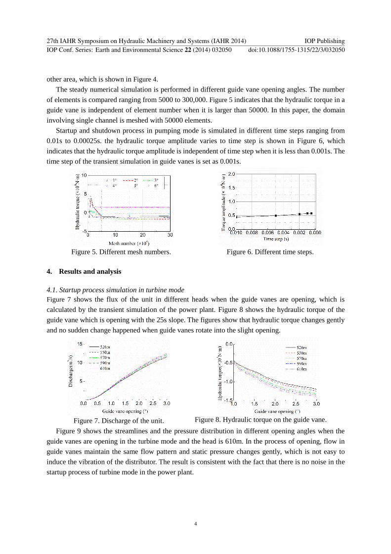
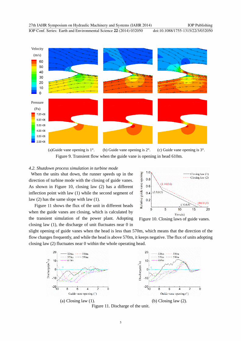
Velocity
(ms)
Pressure
(Pa)
(a)Guide vane opening is 1deg (b) Guide vane opening is 2deg (c) Guide vane opening is 3deg
Figure 9 Transient flow when the guide vane is opening in head 610m
42 Shutdown process simulation in turbine mode
When the units shut down the runner speeds up in the
direction of turbine mode with the closing of guide vanes
As shown in Figure 10 closing law (2) has a different
inflection point with law (1) while the second segment of
law (2) has the same slope with law (1)
Figure 11 shows the flux of the unit in different heads
when the guide vanes are closing which is calculated by
the transient simulation of the power plant Adopting
closing law (1) the discharge of unit fluctuates near 0 in
slight opening of guide vanes when the head is less than 570m which means that the direction of the
flow changes frequently and while the head is above 570m it keeps negative The flux of units adopting
closing law (2) fluctuates near 0 within the whole operating head
(a) Closing law (1) (b) Closing law (2)
Figure 11 Discharge of the unit
Figure 10 Closing laws of guide vanes
27th IAHR Symposium on Hydraulic Machinery and Systems (IAHR 2014) IOP PublishingIOP Conf Series Earth and Environmental Science 22 (2014) 032050 doi1010881755-1315223032050
5
Figure 12 shows the hydraulic torque in a guide vane which is closing As shown in Figure 13 the
time from the maximum hydraulic torque to the minimum is defined as the transition time the max
change of the torque of the guide vane is defined as the torque amplitude and the ratio of the torque
amplitude to transition time is defined as the torque change rate which indicates the average change of
the torque Figure 14 shows the correlation between hydraulic torque changing rate and head The
changing rate of torque is large in low head by using closing law (1) which indicate that flow pattern in
guide vanes changes intensely By using closing law (2) the maximum value of torque change rate
appears when the head is about 550m When the head is above 550m torque change rate of the units
adopting law (2) is significantly greater than the units adopting closing law (1)
(a) Closing law (1) (b) Closing law (2)
Figure 12 Hydraulic torque of the guide vane
Figure 13 Hydraulic torque changing rate Figure 14 Hydraulic torque changing rate in
different heads
Figure 15 shows the streamlines and the pressure distribution in different opening angles of unit
adopting closing law (1) when the guide vanes are closed in the turbine mode and the head is 526m The
flow pattern in the guide vanes changes noticeably because of the repeating reversal flow The
streamlines and the pressure distribution in different opening angles of unit adopting closing law (1)
when the guide vanes are closing in the turbine mode and the head is 610m are shown in Figure 16 The
direction of flow in guide vanes keeps negative and the flow pattern changes smoothly Therefore the
torque change rate is smaller than it at low head
The simulation results indicate that the repeating reversal flow is the main performance of the change
of flow state in guide vanes after load rejection Although the absolute value and change rate is tiny
relative change rate of flux is large when the guide vanes are in slight opening The flux of units adopting
closing law (1) for example fluctuates around 0 at low water head and keeps negative at high head At
low head the relative change rate of flux is much greater than at high head resulting that the torque
change rate is greater
27th IAHR Symposium on Hydraulic Machinery and Systems (IAHR 2014) IOP PublishingIOP Conf Series Earth and Environmental Science 22 (2014) 032050 doi1010881755-1315223032050
6
Velocity
(ms)
Pressure
(Pa)
(a)Guide vane opening is 6deg (b)Guide vane opening is 52deg (c)Guide vane opening is 44deg
Velocity
(ms)
Figure 15 Transient flow
when the guide vane is
closing with law (1) in
head 526m
Pressure
(Pa)
(d)Guide vane opening is 36deg (e)Guide vane opening is 28deg
27th IAHR Symposium on Hydraulic Machinery and Systems (IAHR 2014) IOP PublishingIOP Conf Series Earth and Environmental Science 22 (2014) 032050 doi1010881755-1315223032050
7
Velocity
(ms)
Pressure
(Pa)
(a)Guide vane opening is 5deg (b)Guide vane opening is 34deg (c) Guide vane opening is 18deg
Figure 16 Transient flow when the guide vane is closing with law (1) in head 610m
The water levels of reservoirs recorded when the loud scrape occurs is converted into the operation
head which is called the noise head Figure 17 shows the noise head
distribution when the loud scrape occurs in the shutdown process
using two guide vane closing laws which indicate that noise head
mainly concentrates at the head ranging from 530m to 550m
Comparison of simulation results and plant operation statistics is
shown in Figure 18 and Figure 19 The calculation predict accurately
that the possibility of making noise at low head is greater At high
head conditions units adopting closing law (2) are more likely to
make noises which coincides with the statistic data
Figure 18 Distribution ratio of noise head
(closing law (1))
Figure 19 Distribution ratio of noise head
(closing law (2))
43 Comparison of different guide vanes closing laws
Repeating reversal flow is the cause of the vibration in the sight opening guide vanes when the units
Figure 17 Scattered distribution of noise
head
27th IAHR Symposium on Hydraulic Machinery and Systems (IAHR 2014) IOP PublishingIOP Conf Series Earth and Environmental Science 22 (2014) 032050 doi1010881755-1315223032050
8
shut down In order to restrain the flux fluctuation around 0 different closing laws are analyzed Figure
20 shows the closing laws which have different slope at second segment
Figure 20 Closing laws Figure 21 Discharge of the unit
Figure 21 shows the flux of the unit using different closing laws which is calculated by the transient
simulation of the power plant As can be seen with the acceleration of second segment of the closing
law unit flux increases in reversal direction moves away from 0 gradually
Figure 22 shows the hydraulic torque of a guide vane varies with the closing law Figure 23 shows
the relation between change rate of torque and the slope of second segment of closing law which
indicates that accelerating the closing speed of second segment appropriately can reduce the change rate
of torque of guide vane However with the acceleration of closing speed the maximum pressure of
spiral case inlet and minimum pressure of draft tube inlet are deteriorated which have a negative
influence to the safe operation of the diversion system as shown in Figure 23 (the reference value is the
pressure when the slope of second segment is 25s)
Figure 22 Hydraulic torque of the guide vane Figure 23 Hydraulic torque changing rate of
different closing speed
5 Conclusion
Simulation of the transient flow in the guide vanes indicates the repeating reversal of fluid occurs when
the guide vanes rotate into the slight opening during the shutdown process in turbine mode which results
in the sudden change of the torque When the torque made by the servomotor canrsquot adapt the abrupt
change quickly the vibration and loud scrape maybe occur The larger torque change rate the more
possibility of the vibration and scrape The calculation result is basically in agreement with the statistical
data of the power station
In the end the effect of different closing laws is studied when guide vanes rotate in slight opening
which indicates that accelerating the closing speed appropriately can reduce the reversal flow in guide
27th IAHR Symposium on Hydraulic Machinery and Systems (IAHR 2014) IOP PublishingIOP Conf Series Earth and Environmental Science 22 (2014) 032050 doi1010881755-1315223032050
9
vanes and improve the stability of flow state in guide vanes but the maximum pressure of spiral case
inlet and minimum pressure of draft tube inlet are deteriorated
6 Acknowledgments
The authors would like to thank National Natural Science Foundation of China (No 51279084) and
State Key Laboratory of Hydro Science amp Hydraulic Engineering (2014-KY-05) for their financial
support
Nomenclature
V = absolute velocity
r = radial coordinate
θ = tangential coordinate
t = time
Q = discharge
p = static pressure
= density
= viscosity coefficient
g = gravity acceleration
rA = area
References [1] Kong L H 2004 Exceptional sound in operation switch of high head pump turbine Mechanical and
electrical technology in hydraulic power station (6) 12-14
[2] Ei Sadi H and Esmail N 2006 Simulation of three-dimensional transient performance in micro-pump
Sensors and Actuators (115) 510-518
[3] Wang L Q Li Z F Dai W P and Wu D Z 2008 2-D numerical simulation on transient flow in centrifugal
pump during starting period Journal of engineering thermophysics 29(8) 1319-1322
[4] Wu D Z Xu B J Li Z F and Wang L Q 2009 Numerical simulation on internal flow of centrifugal
pump during transient operation Journal of engineering thermophysics 30(5) 781-783
[5] Zhou D Q Wu Y L and Liu S H 2010 Three-dimensional CFD simulation of the runaway transients
of a propeller turbine model Journal of hydraulic engineering 41(2) 233-238
[6] Li J Yu J and Wu Y 2010 3D unsteady turbulent simulations of transients of the Francis turbine 25th
IAHR Sym on Hydraulic Machinery and Systems (Timisoara Romania)
[7] Kolsek T Duhovnik J and Bergant A 2006 Simulation of unsteady flow and runner rotation during
shut-down of an axial water turbine Journal of Hydraulic Research 44(1) 129-137
[8] Benigni H and Jaberg H 2007 Stationary and transient numerical simulation of a bulb turbine Proc of
the 5th IASMEWSEAS Int Conf on Fluid Mechanics and Aerodynamics (Athens Greece)
[9] Mompean M 1998 Numerical simulation of a turbulent flow near a right-angled corner using the
special non-linear model with RNG k-ε equations Computers amp Fluids 27(7) 847-859
[10] Wang Z W and Zhou L J 2006 Simulation and Measurements of pressure oscillations caused by vortex
ropes Journal of Fluid Engineering 128(6) 649-655
[11] Huang S Yang F X Guo J and Ou G W 2013 Numerical Simulation of 3D Unsteady Flow in
Centrifugal Pump by Dynamic Mesh Technique Science amp Technology Review 31(24) 33-36
27th IAHR Symposium on Hydraulic Machinery and Systems (IAHR 2014) IOP PublishingIOP Conf Series Earth and Environmental Science 22 (2014) 032050 doi1010881755-1315223032050
10
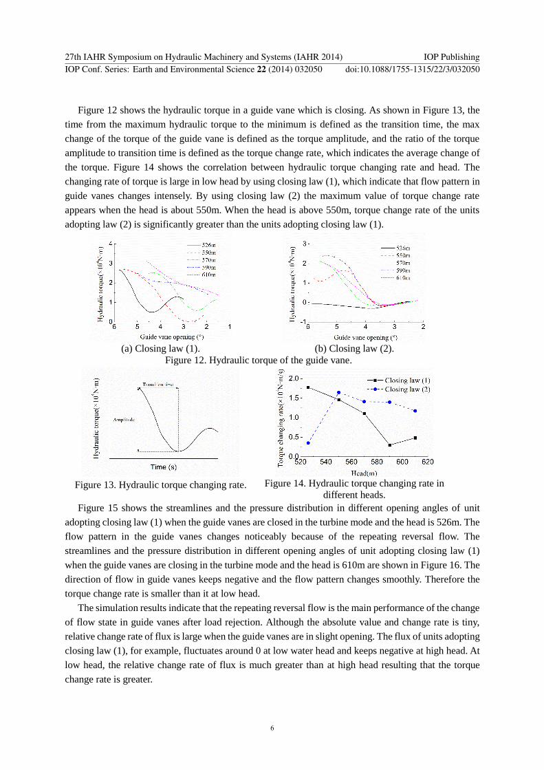
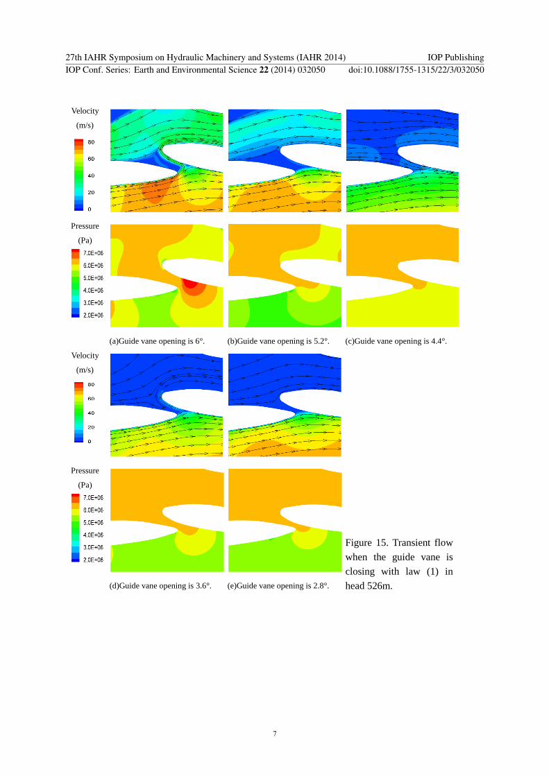
Velocity
(ms)
Pressure
(Pa)
(a)Guide vane opening is 6deg (b)Guide vane opening is 52deg (c)Guide vane opening is 44deg
Velocity
(ms)
Figure 15 Transient flow
when the guide vane is
closing with law (1) in
head 526m
Pressure
(Pa)
(d)Guide vane opening is 36deg (e)Guide vane opening is 28deg
27th IAHR Symposium on Hydraulic Machinery and Systems (IAHR 2014) IOP PublishingIOP Conf Series Earth and Environmental Science 22 (2014) 032050 doi1010881755-1315223032050
7
Velocity
(ms)
Pressure
(Pa)
(a)Guide vane opening is 5deg (b)Guide vane opening is 34deg (c) Guide vane opening is 18deg
Figure 16 Transient flow when the guide vane is closing with law (1) in head 610m
The water levels of reservoirs recorded when the loud scrape occurs is converted into the operation
head which is called the noise head Figure 17 shows the noise head
distribution when the loud scrape occurs in the shutdown process
using two guide vane closing laws which indicate that noise head
mainly concentrates at the head ranging from 530m to 550m
Comparison of simulation results and plant operation statistics is
shown in Figure 18 and Figure 19 The calculation predict accurately
that the possibility of making noise at low head is greater At high
head conditions units adopting closing law (2) are more likely to
make noises which coincides with the statistic data
Figure 18 Distribution ratio of noise head
(closing law (1))
Figure 19 Distribution ratio of noise head
(closing law (2))
43 Comparison of different guide vanes closing laws
Repeating reversal flow is the cause of the vibration in the sight opening guide vanes when the units
Figure 17 Scattered distribution of noise
head
27th IAHR Symposium on Hydraulic Machinery and Systems (IAHR 2014) IOP PublishingIOP Conf Series Earth and Environmental Science 22 (2014) 032050 doi1010881755-1315223032050
8
shut down In order to restrain the flux fluctuation around 0 different closing laws are analyzed Figure
20 shows the closing laws which have different slope at second segment
Figure 20 Closing laws Figure 21 Discharge of the unit
Figure 21 shows the flux of the unit using different closing laws which is calculated by the transient
simulation of the power plant As can be seen with the acceleration of second segment of the closing
law unit flux increases in reversal direction moves away from 0 gradually
Figure 22 shows the hydraulic torque of a guide vane varies with the closing law Figure 23 shows
the relation between change rate of torque and the slope of second segment of closing law which
indicates that accelerating the closing speed of second segment appropriately can reduce the change rate
of torque of guide vane However with the acceleration of closing speed the maximum pressure of
spiral case inlet and minimum pressure of draft tube inlet are deteriorated which have a negative
influence to the safe operation of the diversion system as shown in Figure 23 (the reference value is the
pressure when the slope of second segment is 25s)
Figure 22 Hydraulic torque of the guide vane Figure 23 Hydraulic torque changing rate of
different closing speed
5 Conclusion
Simulation of the transient flow in the guide vanes indicates the repeating reversal of fluid occurs when
the guide vanes rotate into the slight opening during the shutdown process in turbine mode which results
in the sudden change of the torque When the torque made by the servomotor canrsquot adapt the abrupt
change quickly the vibration and loud scrape maybe occur The larger torque change rate the more
possibility of the vibration and scrape The calculation result is basically in agreement with the statistical
data of the power station
In the end the effect of different closing laws is studied when guide vanes rotate in slight opening
which indicates that accelerating the closing speed appropriately can reduce the reversal flow in guide
27th IAHR Symposium on Hydraulic Machinery and Systems (IAHR 2014) IOP PublishingIOP Conf Series Earth and Environmental Science 22 (2014) 032050 doi1010881755-1315223032050
9
vanes and improve the stability of flow state in guide vanes but the maximum pressure of spiral case
inlet and minimum pressure of draft tube inlet are deteriorated
6 Acknowledgments
The authors would like to thank National Natural Science Foundation of China (No 51279084) and
State Key Laboratory of Hydro Science amp Hydraulic Engineering (2014-KY-05) for their financial
support
Nomenclature
V = absolute velocity
r = radial coordinate
θ = tangential coordinate
t = time
Q = discharge
p = static pressure
= density
= viscosity coefficient
g = gravity acceleration
rA = area
References [1] Kong L H 2004 Exceptional sound in operation switch of high head pump turbine Mechanical and
electrical technology in hydraulic power station (6) 12-14
[2] Ei Sadi H and Esmail N 2006 Simulation of three-dimensional transient performance in micro-pump
Sensors and Actuators (115) 510-518
[3] Wang L Q Li Z F Dai W P and Wu D Z 2008 2-D numerical simulation on transient flow in centrifugal
pump during starting period Journal of engineering thermophysics 29(8) 1319-1322
[4] Wu D Z Xu B J Li Z F and Wang L Q 2009 Numerical simulation on internal flow of centrifugal
pump during transient operation Journal of engineering thermophysics 30(5) 781-783
[5] Zhou D Q Wu Y L and Liu S H 2010 Three-dimensional CFD simulation of the runaway transients
of a propeller turbine model Journal of hydraulic engineering 41(2) 233-238
[6] Li J Yu J and Wu Y 2010 3D unsteady turbulent simulations of transients of the Francis turbine 25th
IAHR Sym on Hydraulic Machinery and Systems (Timisoara Romania)
[7] Kolsek T Duhovnik J and Bergant A 2006 Simulation of unsteady flow and runner rotation during
shut-down of an axial water turbine Journal of Hydraulic Research 44(1) 129-137
[8] Benigni H and Jaberg H 2007 Stationary and transient numerical simulation of a bulb turbine Proc of
the 5th IASMEWSEAS Int Conf on Fluid Mechanics and Aerodynamics (Athens Greece)
[9] Mompean M 1998 Numerical simulation of a turbulent flow near a right-angled corner using the
special non-linear model with RNG k-ε equations Computers amp Fluids 27(7) 847-859
[10] Wang Z W and Zhou L J 2006 Simulation and Measurements of pressure oscillations caused by vortex
ropes Journal of Fluid Engineering 128(6) 649-655
[11] Huang S Yang F X Guo J and Ou G W 2013 Numerical Simulation of 3D Unsteady Flow in
Centrifugal Pump by Dynamic Mesh Technique Science amp Technology Review 31(24) 33-36
27th IAHR Symposium on Hydraulic Machinery and Systems (IAHR 2014) IOP PublishingIOP Conf Series Earth and Environmental Science 22 (2014) 032050 doi1010881755-1315223032050
10
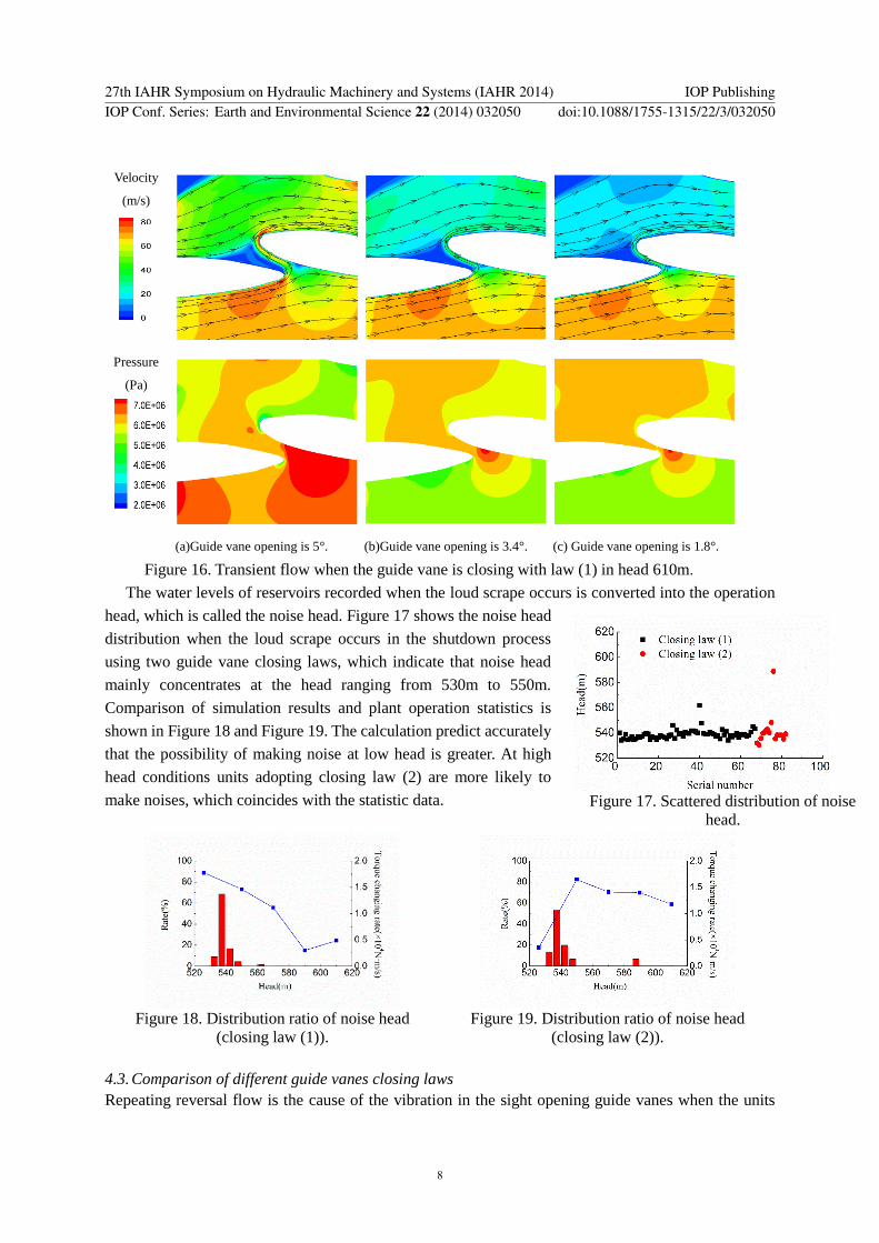
Velocity
(ms)
Pressure
(Pa)
(a)Guide vane opening is 5deg (b)Guide vane opening is 34deg (c) Guide vane opening is 18deg
Figure 16 Transient flow when the guide vane is closing with law (1) in head 610m
The water levels of reservoirs recorded when the loud scrape occurs is converted into the operation
head which is called the noise head Figure 17 shows the noise head
distribution when the loud scrape occurs in the shutdown process
using two guide vane closing laws which indicate that noise head
mainly concentrates at the head ranging from 530m to 550m
Comparison of simulation results and plant operation statistics is
shown in Figure 18 and Figure 19 The calculation predict accurately
that the possibility of making noise at low head is greater At high
head conditions units adopting closing law (2) are more likely to
make noises which coincides with the statistic data
Figure 18 Distribution ratio of noise head
(closing law (1))
Figure 19 Distribution ratio of noise head
(closing law (2))
43 Comparison of different guide vanes closing laws
Repeating reversal flow is the cause of the vibration in the sight opening guide vanes when the units
Figure 17 Scattered distribution of noise
head
27th IAHR Symposium on Hydraulic Machinery and Systems (IAHR 2014) IOP PublishingIOP Conf Series Earth and Environmental Science 22 (2014) 032050 doi1010881755-1315223032050
8
shut down In order to restrain the flux fluctuation around 0 different closing laws are analyzed Figure
20 shows the closing laws which have different slope at second segment
Figure 20 Closing laws Figure 21 Discharge of the unit
Figure 21 shows the flux of the unit using different closing laws which is calculated by the transient
simulation of the power plant As can be seen with the acceleration of second segment of the closing
law unit flux increases in reversal direction moves away from 0 gradually
Figure 22 shows the hydraulic torque of a guide vane varies with the closing law Figure 23 shows
the relation between change rate of torque and the slope of second segment of closing law which
indicates that accelerating the closing speed of second segment appropriately can reduce the change rate
of torque of guide vane However with the acceleration of closing speed the maximum pressure of
spiral case inlet and minimum pressure of draft tube inlet are deteriorated which have a negative
influence to the safe operation of the diversion system as shown in Figure 23 (the reference value is the
pressure when the slope of second segment is 25s)
Figure 22 Hydraulic torque of the guide vane Figure 23 Hydraulic torque changing rate of
different closing speed
5 Conclusion
Simulation of the transient flow in the guide vanes indicates the repeating reversal of fluid occurs when
the guide vanes rotate into the slight opening during the shutdown process in turbine mode which results
in the sudden change of the torque When the torque made by the servomotor canrsquot adapt the abrupt
change quickly the vibration and loud scrape maybe occur The larger torque change rate the more
possibility of the vibration and scrape The calculation result is basically in agreement with the statistical
data of the power station
In the end the effect of different closing laws is studied when guide vanes rotate in slight opening
which indicates that accelerating the closing speed appropriately can reduce the reversal flow in guide
27th IAHR Symposium on Hydraulic Machinery and Systems (IAHR 2014) IOP PublishingIOP Conf Series Earth and Environmental Science 22 (2014) 032050 doi1010881755-1315223032050
9
vanes and improve the stability of flow state in guide vanes but the maximum pressure of spiral case
inlet and minimum pressure of draft tube inlet are deteriorated
6 Acknowledgments
The authors would like to thank National Natural Science Foundation of China (No 51279084) and
State Key Laboratory of Hydro Science amp Hydraulic Engineering (2014-KY-05) for their financial
support
Nomenclature
V = absolute velocity
r = radial coordinate
θ = tangential coordinate
t = time
Q = discharge
p = static pressure
= density
= viscosity coefficient
g = gravity acceleration
rA = area
References [1] Kong L H 2004 Exceptional sound in operation switch of high head pump turbine Mechanical and
electrical technology in hydraulic power station (6) 12-14
[2] Ei Sadi H and Esmail N 2006 Simulation of three-dimensional transient performance in micro-pump
Sensors and Actuators (115) 510-518
[3] Wang L Q Li Z F Dai W P and Wu D Z 2008 2-D numerical simulation on transient flow in centrifugal
pump during starting period Journal of engineering thermophysics 29(8) 1319-1322
[4] Wu D Z Xu B J Li Z F and Wang L Q 2009 Numerical simulation on internal flow of centrifugal
pump during transient operation Journal of engineering thermophysics 30(5) 781-783
[5] Zhou D Q Wu Y L and Liu S H 2010 Three-dimensional CFD simulation of the runaway transients
of a propeller turbine model Journal of hydraulic engineering 41(2) 233-238
[6] Li J Yu J and Wu Y 2010 3D unsteady turbulent simulations of transients of the Francis turbine 25th
IAHR Sym on Hydraulic Machinery and Systems (Timisoara Romania)
[7] Kolsek T Duhovnik J and Bergant A 2006 Simulation of unsteady flow and runner rotation during
shut-down of an axial water turbine Journal of Hydraulic Research 44(1) 129-137
[8] Benigni H and Jaberg H 2007 Stationary and transient numerical simulation of a bulb turbine Proc of
the 5th IASMEWSEAS Int Conf on Fluid Mechanics and Aerodynamics (Athens Greece)
[9] Mompean M 1998 Numerical simulation of a turbulent flow near a right-angled corner using the
special non-linear model with RNG k-ε equations Computers amp Fluids 27(7) 847-859
[10] Wang Z W and Zhou L J 2006 Simulation and Measurements of pressure oscillations caused by vortex
ropes Journal of Fluid Engineering 128(6) 649-655
[11] Huang S Yang F X Guo J and Ou G W 2013 Numerical Simulation of 3D Unsteady Flow in
Centrifugal Pump by Dynamic Mesh Technique Science amp Technology Review 31(24) 33-36
27th IAHR Symposium on Hydraulic Machinery and Systems (IAHR 2014) IOP PublishingIOP Conf Series Earth and Environmental Science 22 (2014) 032050 doi1010881755-1315223032050
10
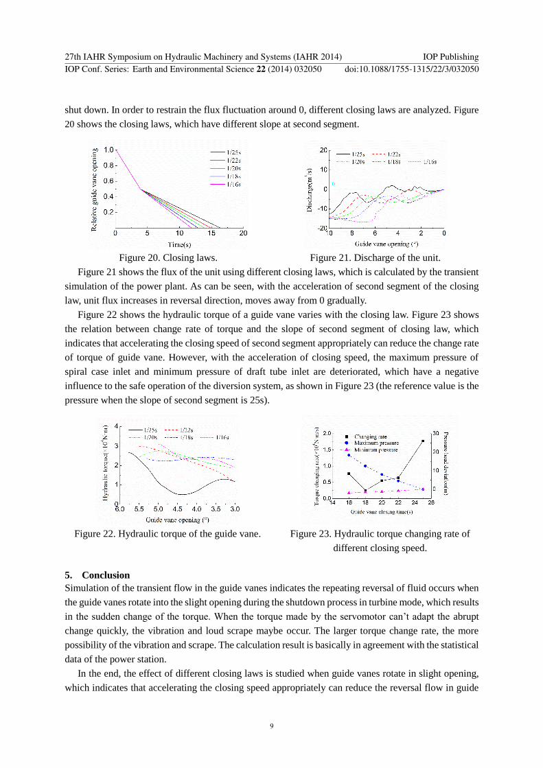
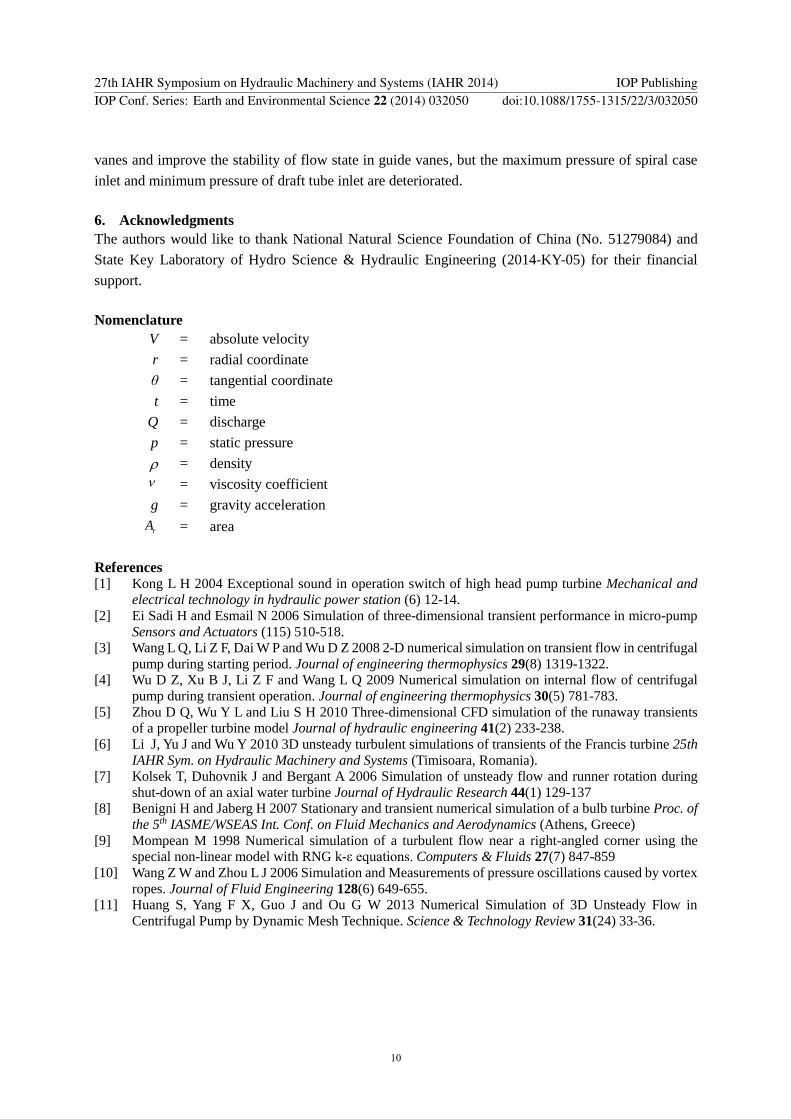