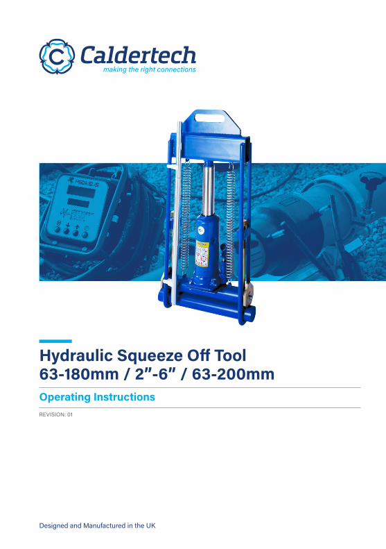
Hydraulic Squeeze Off Tool 63-180mm / 2”-6” / 63-200mm
24
Designed and Manufactured in the UK Hydraulic Squeeze Off Tool 63-180mm / 2”-6” / 63-200mm Operating Instructions REVISION: 01
Transcript of Hydraulic Squeeze Off Tool 63-180mm / 2”-6” / 63-200mm
Designed and Manufactured in the UK
Hydraulic Squeeze Off Tool 63-180mm / 2”-6” / 63-200mm Operating InstructionsREVISION: 01

© Copyright Caldervale Technology Ltd.The copyright for this product and instruction manual is held by Caldervale Technology Ltd. Any technical specifications, or illustrations part of this manual cannot be reproduced, used illicitly or distributed in any form for competitive purposes.
Helping you make the right connections.
Operating Instructions Hydraulic Squeeze Off Tool 180mm / 6” IPS / 200mm
01
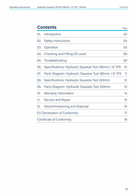
Contents01. Introduction 02
02. Safety Instructions 04
03. Operation 05
04. Checking and Filling Oil Level 08
05. Troubleshooting 09
06. Specifications: Hydraulic Squeeze Tool 180mm / 6” IPS 10
07. Parts Diagram: Hydraulic Squeeze Tool 180mm / 6” IPS 11
08. Specifications: Hydraulic Squeeze Tool 200mm 12
09. Parts Diagram: Hydraulic Squeeze Tool 200mm 13
10. Warranty Information 14
11. Service and Repair 15
12. Decommissioning and Disposal 15
EU Declaration of Conformity 17
Certificate of Conformity 18
Page
Contents
Operating Instructions Hydraulic Squeeze Off Tool 180mm / 6” IPS / 200mm
02
01. Introduction
Introduction
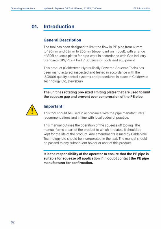
General DescriptionThe tool has been designed to limit the flow in PE pipe from 63mm to 180mm and 63mm to 200mm (dependant on model), with a range of SDR squeeze plates for pipe work in accordance with Gas Industry Standards GIS/PL2-7 Part 7 Squeeze-off tools and equipment.
This product (Caldertech Hydraulically Powered Squeeze Tools) has been manufactured, inspected and tested in accordance with the ISO9001 quality control systems and procedures in place at Caldervale Technology Ltd, Dewsbury.
The unit has rotating pre-sized limiting plates that are used to limit the squeeze gap and prevent over compression of the PE pipe.
Important!This tool should be used in accordance with the pipe manufacturers recommendations and in line with local codes of practice.
This manual outlines the operation of the squeeze off tooling. The manual forms a part of the product to which it relates. It should be kept for the life of the product. Any amendments issued by Caldervale Technology Ltd should be incorporated in the text. The manual should be passed to any subsequent holder or user of this product.
It is the responsibility of the operator to ensure that the PE pipe is suitable for squeeze off application if in doubt contact the PE pipe manufacturer for confirmation.
01.
Operating Instructions Hydraulic Squeeze Off Tool 180mm / 6” IPS / 200mm
03
01. Introduction
Before UsingCheck the level of oil in the jack to ensure at correct level.
It is important to ensure all component parts are present and in serviceable condition. In addition, the setting of the limit stop (buffer) plates should be checked before every operation to ensure they are correct for the pipe size and wall thickness rating. Wrongly set buffer plates may cause insufficient or excessive pipe compression leading to pipe-wall damage, leakage or injury.
First Use ProcedureBefore operating the tool for the first time, the jack must have its hydraulic circuit ‘purged’ to eliminate any possible air in the system.
To Purge the System
1. Open the jack control valve using the jack handle, turning it anti-clockwise and then, with the aid of the handle operate the hydraulic jack several times.
2. Close the jack control valve fully using the jack handle. The tool is now ready for use.
Operating Instructions Hydraulic Squeeze Off Tool 180mm / 6” IPS / 200mm
04
02. Safety Instructions
Safety Instructions
1. Read and understand the whole booklet before using the tool
2. Read FIRST USE procedure before using the tool.
3. It is imperative that all possible precautions are made to avoid unexpected movement of the tool during use.
4. Never operate the jack beyond its maximum stroke.
5. The jack is fitted with a safety valve to stop overloading. This is factory set and MUST NOT be tampered with.
6. The tool is heavy (36-37Kg) care should be taken when in use.
7. To avoid injury the bottom bars should be locked in position with the jack extended for transportation (see Transport and storage Page 9)
8. Lifting must be by 2 persons.
9. Operatives should wear eye protection, gloves, safety headwear & footwear when using the equipment.
10. A single squeeze tool cannot be guaranteed to provide 100% closure, where this is required users are advised to consider using 2 squeeze tools.
02.
Operating Instructions Hydraulic Squeeze Off Tool 180mm / 6” IPS / 200mm
05
03. Operation
Instructions for Use1. Unscrew the 2 check screws until the threads are clear of the
threaded blocks.
2. Locate the pressure control valve on the hydraulic jack. The tip of the jack handle will connect onto this. Unscrew the control valve until any internal pressure in the jack is released. The jack and squeeze bar assembly will be retracted under the pressure of the return springs.
3. Remove the Bottom bar from the loops in the mainframe.
4. Set the limit stop (buffer) plates to the correct pipe diameter and rating (SDR) of the pipe to be squeezed. If the plates do not have the correct sizes, check the other set exchange if necessary. The plates
Operation03.
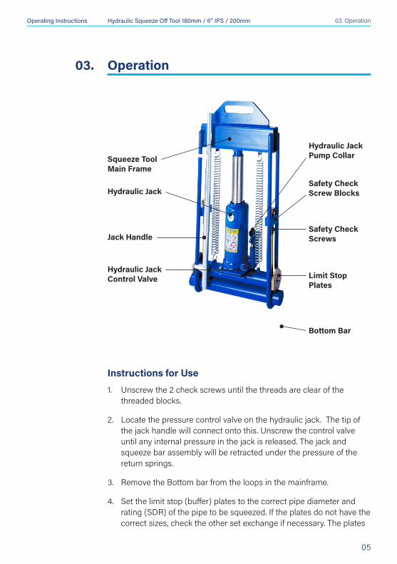
Hydraulic Jack
Squeeze Tool Main Frame
Safety Check Screw Blocks
Safety Check Screws
Limit Stop Plates
Hydraulic Jack Control Valve
Hydraulic Jack Pump Collar
Jack Handle
Bottom Bar
Operating Instructions Hydraulic Squeeze Off Tool 180mm / 6” IPS / 200mm
06
03. Operation
are set correctly when the correct end face is pointing downwards and positioned to contact the bottom bar when this is re-fitted.
5. Position the mainframe over the pipe to be squeezed and slide the bottom bar into the loops of the mainframe beneath the pipe, position the pipe centrally between the squeeze bar and bottom bar.
6. Close the Hydraulic Jack control valve by screwing clockwise using the jack handle.
7. Fit the jack handle into the collar of the pump on the jack. Commence pumping the jack to apply the squeeze pressure.
8. Continue the pumping action until the squeeze bar has fully closed the pipe, and the limit stop plates prevent further compression.
9. Screw down both check screws until they are in contact with the upper edge of the squeeze bar. This will prevent any loss of squeeze pressure in the event of hydraulic pressure leakage in the jack.
Removal After Squeeze OffOn completion of the squeeze off operation, remove the tool as follows:
1. Unscrew the check screws until their threads are clear of the safety check screws threaded blocks. (If it is difficult to release the check screws, pump the jack handle 2 or 3 times to replace any loss of hydraulic pressure).
2. Gently release the hydraulic jack pressure by unscrewing the pressure control valve anti clockwise with the jack handle. This may require carrying out in controlled stages to prevent flow surges and excessive pressure drops in the pipe-work as the system fills up.
3. Allow the jack and squeeze bar to retract fully in the main frame under the force of the return springs, remove the bottom bar and lift the main frame clear of the pipe.
4. Allow the section of squeezed pipe to reform to its original shape, this may take several hours.
5. A selection of post squeeze-off re-rounding tools are available to aid the pipe in regaining its original shape, vistit www.caldertech.com
Operating Instructions Hydraulic Squeeze Off Tool 180mm / 6” IPS / 200mm
07
03. Operation
Transport1. Replace the Bottom Bar into the Frame. Turn the Release Valve fully
clockwise using the jacking handle.
2. Fit the jacking handle into the handle socket and ‘pump’ up the jack.
3. Continue jacking until the Limit Plates just come into contact with the Bottom Bar. Refit both check screws and tighten against the Squeeze Bars.
4. Using the Jacking Handle turn the Release Valve on the Hydraulic Jack in an anticlockwise direction. This will release the oil pressure in the jack.
StorageIMPORTANT! When not in use always:
1. Store the tool in an upright position.
2. Ensure the pressure in the jack is released.
3. Ensure the tool is clean and dry before storing.
Routine Maintenance1. Before each operation, ensure that the jack has sufficient oil, remove
the filler plug and check that the oil level is correct.
2. Lubricate all moving parts at regular intervals.
3. Grease check screw threads at regular intervals.
Note: Checking the oil level in any way other than quoted in this manual may severely limit or render the jack inoperative.
Operating Instructions Hydraulic Squeeze Off Tool 180mm / 6” IPS / 200mm
08
04. Checking and Filling Oil Level
Checking and Filling Oil Level
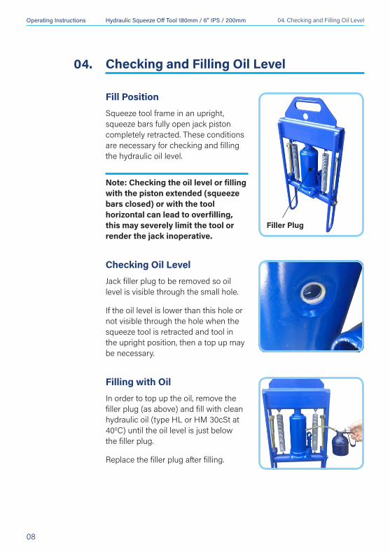
Fill PositionSqueeze tool frame in an upright, squeeze bars fully open jack piston completely retracted. These conditions are necessary for checking and filling the hydraulic oil level.
Note: Checking the oil level or filling with the piston extended (squeeze bars closed) or with the tool horizontal can lead to overfilling, this may severely limit the tool or render the jack inoperative.
Checking Oil LevelJack filler plug to be removed so oil level is visible through the small hole.
If the oil level is lower than this hole or not visible through the hole when the squeeze tool is retracted and tool in the upright position, then a top up may be necessary.
Filling with OilIn order to top up the oil, remove the filler plug (as above) and fill with clean hydraulic oil (type HL or HM 30cSt at 400C) until the oil level is just below the filler plug.
Replace the filler plug after filling.
04.
Filler Plug
Operating Instructions Hydraulic Squeeze Off Tool 180mm / 6” IPS / 200mm
09
05. Troubleshooting
Troubleshooting
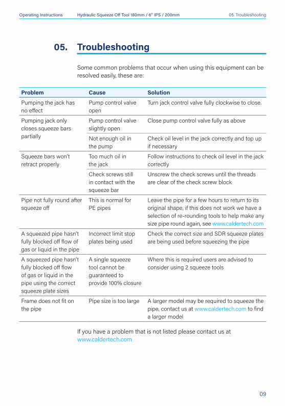
Some common problems that occur when using this equipment can be resolved easily, these are:
05.
Problem Cause Solution
Pumping the jack has no effect
Pump control valve open
Turn jack control valve fully clockwise to close.
Pumping jack only closes squeeze bars partially
Pump control valve slightly open
Close pump control valve fully as above
Not enough oil in the pump
Check oil level in the jack correctly and top up if necessary
Squeeze bars won’t retract properly
Too much oil in the jack
Follow instructions to check oil level in the jack correctly
Check screws still in contact with the squeeze bar
Unscrew the check screws until the threads are clear of the check screw block
Pipe not fully round after squeeze off
This is normal for PE pipes
Leave the pipe for a few hours to return to its original shape, if this does not work we have a selection of re-rounding tools to help make any size pipe round again, see www.caldertech.com
A squeezed pipe hasn’t fully blocked off flow of gas or liquid in the pipe
Incorrect limit stop plates being used
Check the correct size and SDR squeeze plates are being used before squeezing the pipe
A squeezed pipe hasn’t fully blocked off flow of gas or liquid in the pipe using the correct squeeze plate sizes
A single squeeze tool cannot be guaranteed to provide 100% closure
Where this is required users are advised to consider using 2 squeeze tools
Frame does not fit on the pipe
Pipe size is too large A larger model may be required to squeeze the pipe, contact us at www.caldertech.com to find a larger model
If you have a problem that is not listed please contact us at www.caldertech.com

Operating Instructions Hydraulic Squeeze Off Tool 180mm / 6” IPS / 200mm
10
06. Specifications: 180mm / 6” IPS
Specifications: Hydraulic Squeeze Tool 63-180mm / 2”-6” IPS
Materials: Mild Steel EN3A, Chrome Plated Tube
Finish: Powder Coating / Zinc Plated (Steel)
Pipe Diameter: 63mm - 180mm All SDR Ratings
Dimensions (HxWxD): 750mm x 370mm x 100mm
Weight: 36kg
Hydraulic Jack: Rated for 15 Ton
Oil Type: Hydraulic Jack Mineral (type HL or HM 30cSt at 400C)
Product Code: 02-31-601 63, 90, 125 & 180mm SDR 11/17.602-31-602 63, 90, 110, 125, 140, 160 & 180mm SDR 11/1702-31-603 2”, 3”, 4” & 6” IPS02-31-604 63, 90, 110, 125, 140, 160 & 180mm SDR 11/1702-31-605 63, 90, 110, 125, 140, 160 & 180mm SDR 1702-31-606 63, 90, 110, 125, 140, 160 & 180mm SDR 11/17/21
This unit is design and manufactured to meet the requirements of National Grid Gas Industry Standards GIS/PL2-7 Part 7 Squeeze-off tools and equipment.
Caldervale Technology Ltd has a policy of continuous improvement in product quality and design. Caldervale Technology Ltd therefore reserves the right to change the specification of its models at any time, without prior notice.
It is the responsibility of the operator to ensure that the PE pipe is suitable for squeeze off application if in doubt contact the PE pipe manufacturer for confirmation.
06.
Operating Instructions Hydraulic Squeeze Off Tool 180mm / 6” IPS / 200mm
11
07. Parts Diagram: 180mm / 6” IPS
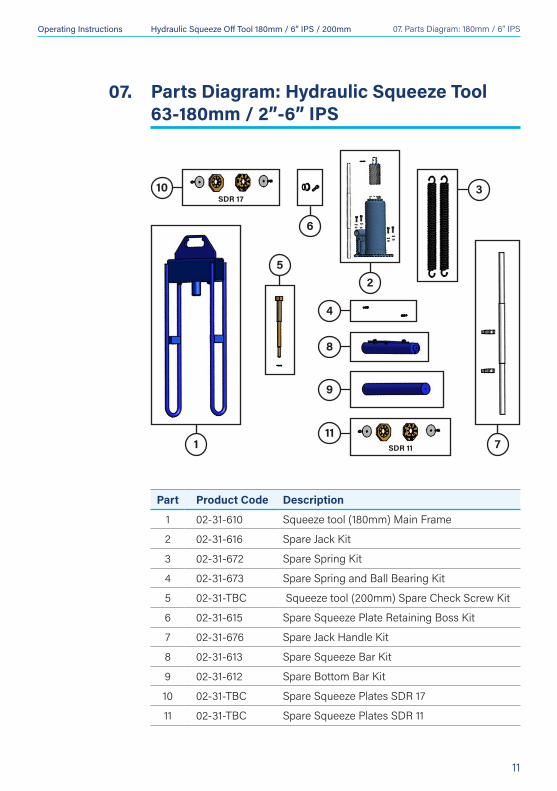
Parts Diagram: Hydraulic Squeeze Tool 63-180mm / 2”-6” IPS
07.
Part Product Code Description
1 02-31-610 Squeeze tool (180mm) Main Frame
2 02-31-616 Spare Jack Kit
3 02-31-672 Spare Spring Kit
4 02-31-673 Spare Spring and Ball Bearing Kit
5 02-31-TBC Squeeze tool (200mm) Spare Check Screw Kit
6 02-31-615 Spare Squeeze Plate Retaining Boss Kit
7 02-31-676 Spare Jack Handle Kit
8 02-31-613 Spare Squeeze Bar Kit
9 02-31-612 Spare Bottom Bar Kit
10 02-31-TBC Spare Squeeze Plates SDR 17
11 02-31-TBC Spare Squeeze Plates SDR 11
3
71
5
10
6
2
SDR 17
11
9
8
4
SDR 11

Operating Instructions Hydraulic Squeeze Off Tool 180mm / 6” IPS / 200mm
12
08. Specifications: 200mm
Specifications: Hydraulic Squeeze Tool 63-200mm
Materials: Mild Steel EN3A, Chrome Plated Tube
Finish: Powder Coating / Zinc Plated (Steel)
Pipe Diameter: 63mm - 200mm All SDR Ratings
Dimensions (HxWxD): 750mm x 370mm x 100mm
Weight: 37kg
Hydraulic Jack: Rated for 15 Ton
Oil Type: Hydraulic Jack Mineral (type HL or HM 30cSt at 400C)
Product Code: 02-31-650 75, 90, 110, 125, 140, 160, 180 & 200mm SDR 1102-31-651 75, 90, 110, 125, 140, 160, 180 & 200mm SDR 1702-31-652 75, 90, 110, 125, 140, 160, 180 & 200mm SDR 11/17
This unit is design and manufactured to meet the requirements of National Grid Gas Industry Standards GIS/PL2-7 Part 7 Squeeze-off tools and equipment.
Caldervale Technology Ltd has a policy of continuous improvement in product quality and design. Caldervale Technology Ltd therefore reserves the right to change the specification of its models at any time, without prior notice.
It is the responsibility of the operator to ensure that the PE pipe is suitable for squeeze off application if in doubt contact the PE pipe manufacturer for confirmation.
08.
Operating Instructions Hydraulic Squeeze Off Tool 180mm / 6” IPS / 200mm
13
09. Parts Diagram: 200mm
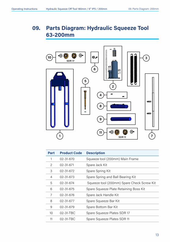
Parts Diagram: Hydraulic Squeeze Tool 63-200mm
09.
Part Product Code Description
1 02-31-670 Squeeze tool (200mm) Main Frame
2 02-31-671 Spare Jack Kit
3 02-31-672 Spare Spring Kit
4 02-31-673 Spare Spring and Ball Bearing Kit
5 02-31-674 Squeeze tool (200mm) Spare Check Screw Kit
6 02-31-675 Spare Squeeze Plate Retaining Boss Kit
7 02-31-676 Spare Jack Handle Kit
8 02-31-677 Spare Squeeze Bar Kit
9 02-31-679 Spare Bottom Bar Kit
10 02-31-TBC Spare Squeeze Plates SDR 17
11 02-31-TBC Spare Squeeze Plates SDR 11
3
71
5
10
6
2
SDR 17
11
9
8
4
SDR 11
Operating Instructions Hydraulic Squeeze Off Tool 180mm / 6” IPS / 200mm
14
Warranty Information
1. Extent of Warrantya) Subject to clauses 2 and 3, Caldervale Technology Ltd warrants to
the end-user customer that its products will be free from defects in materials and workmanship, for six months after the date of purchase by the end-user customer, subject to providing proof of purchase.
b) If Caldervale Technology Ltd receives, during the warranty period, notice of a defect in product which is covered by this warranty; Caldervale Technology Ltd shall either repair or replace the product, at its option. Any replacement product may be either new or like-new, provided that it has functionality at least equal to that of the product being replaced.
c) All warranty work will be carried out by Caldervale Technology Ltd unless otherwise agreed. On-site warranty and repair or replacement services are available from authorised Caldervale Technology Ltd service facilities world-wide.
d) Customers shall prepay shipping charges for products returned to Caldervale Technology Ltd for warranty service, and Caldervale Technology Ltd will charge for return of the products back to the customer.
e) This warranty statement gives the customer specific legal rights. The customer may also have other rights which vary from country to country in the world.
2. Pre-conditions for Warranty ApplicationCaldervale Technology Ltd’s warranty covers only those defects which arise as a result of normal use of the product, and this warranty shall only apply in the following circumstances:
a) All the instructions contained in the operating manual have been complied with; and
b) None of the following apply:i) Improper or inadequate maintenance;ii) Physical abuse;iii) Unauthorised modification, misuse or any use not in accordance
with the operating manual and good industry practice;
10.
10. Warranty Information
Operating Instructions Hydraulic Squeeze Off Tool 180mm / 6” IPS / 200mm
15
iv) Operation outside the products specifications;v) Improper site preparation or maintenance;vi) Faulty pipes.
3. Limitations of Warrantya) Caldervale Technology Ltd does not warrant the operation of any
product to be uninterrupted or error free.
b) Caldervale Technology Ltd makes no other warranty of any kind, whether express or implied, with respect to its products. Caldervale Technology Ltd specifically disclaims the implied warranties of satisfactory quality and fitness for a particular purpose.
c) To the extent that this warranty statement is inconsistent with the law of the locality where the customer uses the product, this warranty statement shall be deemed modified by the minimum necessary to be consistent with such local law.
d) To the extent allowed by local law, the remedies provided in this warranty statement are the customer’s sole and exclusive remedies.
e) This tool has been designed for the range of pipes available at the time of its design and development. Caldervale Technology Ltd can accept NO liability for the unit’s ability or otherwise to work with new or different pipes that subsequently appear in the market place.
Please complete this information and keep it safely with your proof of purchase receipt. You will require it for any warranty claim.
Where purchased:
Date of purchase:
Name of purchaser:
Address of purchaser:
Type of tool:
Serial number:
10. Warranty Information
Operating Instructions Hydraulic Squeeze Off Tool 180mm / 6” IPS / 200mm
16
11. Service and Repair
Service and Repair
For service and repair please contact:
INTERNATIONAL AUSTRALIA / NZCaldervale Technology Ltd Caldertech Australia Pty Ltd Bretfield Court, Dewsbury, Unit 3/30 Juna Drive, West Yorkshire WF12 9BG, UK Malaga WA 6090, AustraliaT. +44 (0)1924 469571 T. +61 (0)8 9209 1132 E. [email protected] E. [email protected] W. caldertech.com W. caldertech.com.au
Decommissioning and Disposal
These give the instructions for decommissioning and disposal of the equipment and confirm how it is to be taken out of service safely, in respect of the Essential Environmental, Health and Safety Requirements.
• If a Caldertech Hydraulically Powered Squeeze tool has reached the end of its useful working life and cannot be refurbished it must be sent to a licensed recycling facility for treatment. That will ensure the waste hierarchy requirements are met.
• End of life treatment is the responsibility of the Customer. This can also be achieved by returning the product back to the manufacturer if required.
11.
12.
Operating Instructions Hydraulic Squeeze Off Tool 180mm / 6” IPS / 200mm
17
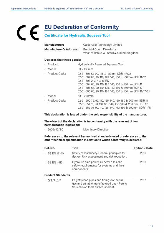
EU Declaration of Conformity
EU Declaration of ConformityCertificate for Hydraulic Squeeze Tool
Manufacturer: Caldervale Technology LimitedManufacturer’s Address: Bretfield Court, Dewsbury, West Yorkshire WF12 9BG, United Kingdom
Declares that these goods:• Product: Hydraulically Powered Squeeze Tool• Model: 63 – 180mm• Product Code: 02-31-601 63, 90, 125 & 180mm SDR 11/17.6 02-31-602 63, 90, 110, 125, 140, 160 & 180mm SDR 11/17 02-31-603 2, 3, 4 & 6 IPS 02-31-604 63, 90, 110, 125, 140, 160 & 180mm SDR 11 02-31-605 63, 90, 110, 125, 140, 160 & 180mm SDR 17 02-31-606 63, 90, 110, 125, 140, 160 & 180mm SDR 11/17/21• Model: 63 – 200mm• Product Code: 02-31-650 75, 90, 110, 125, 140, 160, 180 & 200mm SDR 11 02-31-651 75, 90, 110, 125, 140, 160, 180 & 200mm SDR 17 02-31-652 75, 90, 110, 125, 140, 160, 180 & 200mm SDR 11/17
This declaration is issued under the sole responsibility of the manufacturer.
The object of the declaration is in conformity with the relevant Union harmonisation legislation:• 2006/42/EC Machinery Directive
References to the relevant harmonised standards used or references to the other technical specification in relation to which conformity is declared:
Ref. No. Title Edition / Date
• BS EN 12100 Safety of machinery. General principles for design. Risk assessment and risk reduction.
2010
• BS EN 4413 Hydraulic fluid power. General rules and safety requirements for systems and their components.
2010
Product Standards
• GIS/PL2-7 Polyethylene pipes and fittings for natural gas and suitable manufactured gas - Part 7: Squeeze-off tools and equipment.
2013
Operating Instructions Hydraulic Squeeze Off Tool 180mm / 6” IPS / 200mm
18
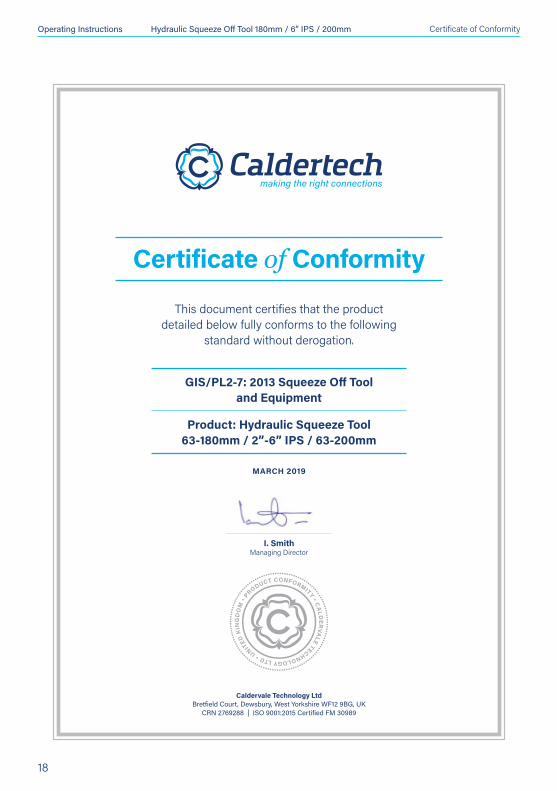
Certificate of Conformity
Caldervale Technology LtdBretfield Court, Dewsbury, West Yorkshire WF12 9BG, UK
CRN 2769288 | ISO 9001:2015 Certified FM 30989
This document certifies that the product detailed below fully conforms to the following
standard without derogation.
GIS/PL2-7: 2013 Squeeze Off Tool and Equipment
Product: Hydraulic Squeeze Tool 63-180mm / 2”-6” IPS / 63-200mm
MARCH 2019
I. Smith Managing Director
Certificate of Conformity

Operating Instructions Hydraulic Squeeze Off Tool 180mm / 6” IPS / 200mm
19
Notes

Operating Instructions Hydraulic Squeeze Off Tool 180mm / 6” IPS / 200mm
20
Notes

INTERNATIONAL
Caldervale Technology Ltd Bretfield Court, Dewsbury, West Yorkshire WF12 9BG, UK
T. +44 (0)1924 469571 E. [email protected] W. caldertech.com
AUSTRALIA / NZ
Caldertech Australia Pty Ltd Unit 3/30 Juna Drive, Malaga WA 6090, Australia
T. +61 (0)8 9209 1132 E. [email protected] W. caldertech.com.au