Hydraulic Control Valve - pressureboss.com · Hydraulic Control Valve > Pressure Control Valve >...
46
Hydraulic Control Valve Pressure Control Valve Flow Control Valve Directional Control Valve www.pressureboss.com
Transcript of Hydraulic Control Valve - pressureboss.com · Hydraulic Control Valve > Pressure Control Valve >...

Hydraulic Control Valve Pressure Control Valve
Flow Control Valve
Directional Control Valve
www.pressureboss.com


www.pressureboss.com Contents 03
Contents Hydraulic Control Valve
Pressure Control Valve
Remote Control Relief Valve ..................................... DG, DT .................. 04
Direct Control Type Relief Valve ............................... DG, DT .................. 04
Pilot Operated Relief Valve ....................................... RV-T ......................... 06
Pilot Operated Relief Valve ....................................... BG .......................... 08
Solenoid Controlled Relief Valve .............................. BSG, BST-1P .......... 10
Solenoid Controlled Relief Valve .............................. BSG, BST-2P, 3P .. 12
Low Noise Type Pilot Operated Relief Valve ............. SBG ....................... 14
Low Noise Type Solenoid Controlled Relief Valve .... SBSG .................... 16
H Type Pressure Control Valve ................................. HG, HT .................. 18
HC Type Pressure Control Valve .............................. HCG, HCT ............. 21
Pressure Reducing Valve .......................................... RG, RT................... 24
Pressure Reducing and Check Valve ....................... RCG, RCT ............. 27
Flow Control Valve
Throttle Valve ........................................................... SRG, SRT .............. 30
Throttle and Check Valve ......................................... SRCG, SRCT......... 32
Solenoid Operated Flow Control Valve ... SF, SDF, THF, SD, SFD, SKF .. 34
Directional Control Valve
Check Valve ............................................................. CRG ....................... 37
Pilot Operated Check Valve .................... CPG, CPT, CPDG, CPDT ....... 38
Pilot Operated Directional Valve ............................... DHG ....................... 40
04 DG, DT www.pressureboss.com
SYMBOLS
ORDER CODES
D G - 01 - 1 - 30
1 2 3 4 5
Model Max. Pressure
( kgf/cm2 )
Pressure Adj. Range ( kgf/cm
2 )
Rated Flow ( l/min )
Weight ( kg ) Sub-Plate
Mounting
Threaded
Connection
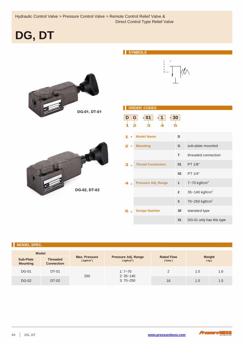
DG-01 DT-01
250
1: 7~70
2: 35~140
3: 70~250
2 1.5 1.6
DG-02 DT-02 16 1.5 1.5
Hydraulic Control Valve > Pressure Control Valve > Remote Control Relief Valve &
Direct Control Type Relief Valve
DG, DT
1 Model Name D
2 Mounting G sub-plate mounted
T threaded connection
3 Thread Connection 01 PT 1/8"
02 PT 1/4"
4 Pressure Adj. Range 1 7~70 kgf/cm2
2 35~140 kgf/cm2
3 70~250 kgf/cm2
5 Design Number 30 standard type
31 DG-01 only has this type
MODEL SPEC.
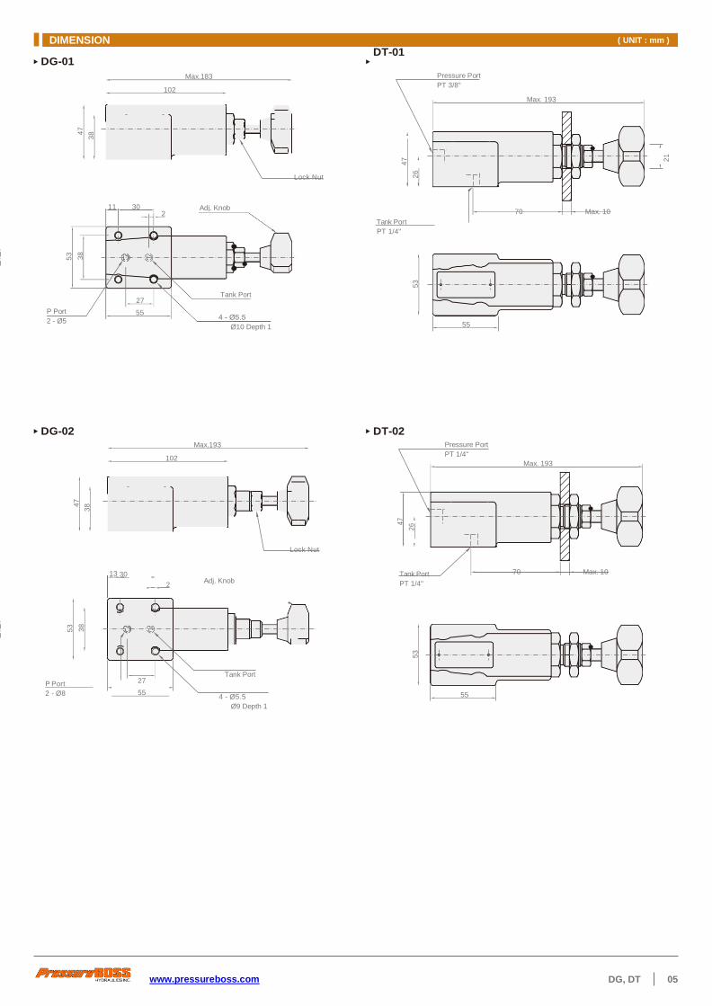
DIMENSION ( UNIT : mm )
www.pressureboss.com DG, DT 05
DG-01
Max.183
102
DT-01
Pressure Port
PT 3/8"
Max. 193
Lock Nut
Tank Port
PT 1/4"
70 Max. 10
DG-02 Max.193
102
DT-02 Pressure Port
PT 1/4"
Max. 193
Lock Nut
13 30
2 Adj. Knob
Tank Port
PT 1/4"
70 Max. 10
P Port
2 - Ø8
27
55
Tank Port
4 - Ø5.5
Ø9 Depth 1
55
55
11 30 Adj. Knob
P Port
2 - Ø5
27
55
Tank Port
Ø10 Depth 1
53
38
53
38
47
38
47
38
47
26
47
2
6
53
53
21

06 RV-T www.pressureboss.com
SYMBOLS
ORDER CODES
- - -
1 2 3 4 5
1 Model Name RV
2 Mounting T threaded connection
3 Thread Connection 04 PT 1/2"
06 PT 3/4"
10 PT 1 1/4"
4 Pressure Adj. Range 1 7~70 kgf/cm2
2 35~140 kgf/cm2
3 70~250 kgf/cm2
5 Design Number 30 standard type
31 adjust directly type
Model Max. Pressure
( kgf/cm2 )
Pressure Adj. Range ( kgf/cm
2 )
Max. Flow ( l/min )
Weight ( kg )
RV-T04
250
1: 7~70
2: 35~140
3: 70~250
80 2.7
RV-T06 200 4
RV-T10 400 9
Hydraulic Control Valve > Pressure Control Valve > Pilot Operated Relief Valve
RV-T
MODEL SPEC.
30 RV T 06
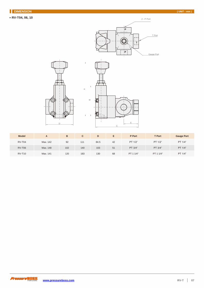
DIMENSION ( UNIT : mm )
www.pressureboss.com RV-T 07
RV-T04, 06, 10 2 - P Port
Model A B C D E P Port T Port Gauge Port
RV-T04 Max. 142 92 111 84.5 42 PT 1/2” PT 1/2” PT 1/4”
RV-T06 Max. 148 102 140 103 51 PT 3/4” PT 3/4” PT 1/4”
RV-T10 Max. 141 120 183 130 68 PT 1 1/4" PT 1 1/4" PT 1/4”
P
T Port
T
P Gauge Port
D
A
B

08 BG www.pressureboss.com
SYMBOLS
ORDER CODES
B G - 06 - 3 - 30
1 2 3 4 5
1 Model Name B
2 Mounting G sub-plate mounted
3 Thread Connection 03 PT 3/8"
06 PT 3/4"
10 PT 1 1/4"
4 Pressure Adj. Range 1 7~70 kgf/cm2
2 35~140 kgf/cm2
3 70~250 kgf/cm2
5 Design Number 30 standard type
31 adjust directly type
Model Max. Pressure
( kgf/cm2 )
Pressure Adj. Range ( kgf/cm
2 )
Max. Flow ( l/min )
Weight ( kg )
BG-03
250
1: 7~70
2: 35~140
3: 70~250
100 5
BG-06 200 6.2
BG-10 400 12.5
Hydraulic Control Valve > Pressure Control Valve > Pilot Operated Relief Valve
BG
MODEL SPEC.

DIMENSION ( UNIT : mm )
www.pressureboss.com BG 09
104 Adj. Knob
Vent Port
Gauge Port
PT 1/4"
P Port
Tank Port 53.8
82
Vent Port
Gauge Port
PT 1/4"
P Port
Tank Port
BG-03
165
BG-06, 10
A Adj. Knob
Model A B C D E F G H I J
BG-06 175 104 160 104 70 66.7 44.5 11 19.5 122
BG-10 184 120 195 125 82.6 88.9 63.6 12.7 18.5 150
C
14
1
47
.5
G
H
22
I F
2
1.5
5
3.8
J

10 BSG, BST-1P www.pressureboss.com
1PN 03
ORDER CODES
- - - -
1 2 3 4 5 6
SYMBOLS
“A”
b
“B”
b
“A”
a
“B”
b
“B”
b
“A” “B”
b
“A”
a
“B”
b
2B3A 2B2B 3C2 2B3B 2B2 3C3
Model Max. Pressure
( kgf/cm2 )
Pressure Adj. Range ( kgf/cm
2 )
Max. Flow ( l/min )
Weight ( kg )
BSG-03
250
1: 7~70
2: 35~140
3: 70~250
100 5.6
BSG-06 BST-06 200 7.1 4.8
BSG-10 BST-10 400 11.8 7.9
Hydraulic Control Valve > Pressure Control Valve > Solenoid Controlled Relief Valve
BSG, BST-1P
MODEL SPEC.
1 Model Name BS
2 Mounting G sub-plate mounted
T threaded connection
3 Thread Connection 03 PT 3/8"
06 PT 3/4"
10 PT 1 1/4"
4 Vent Type 1PN normally vented
1NP energized to vent
5 Pressure Adj. Range 1 7~70 kgf/cm2
2 35~140 kgf/cm2
3 70~250 kgf/cm2
6 Design Number 30 standard type
31 adjust directly type
BS G 30

DIMENSION ( UNIT : mm )
www.pressureboss.com BSG, BST-1P 11
N
M
J
K
L
BSG-03, 06, 10-1PN/1NP
4 - ØY
ØZ Depth 2
Vent Port Gauge Port
PT 1/4"
P Port
Tank Port H
G
E
D
C
Max. B
Model A B C D E G H J K L M N Y Z
BSG-03 223 175 78 78 57 82 53.8 21.5 53.8 0 47.5 22 13.5 21
BSG-06 249 175 78 60 40 104 70 19 66.7 23.8 55.5 11 17.5 26
BSG-10 287 184 87.5 67 47 125 82.6 18.5 88.9 31.8 76.2 12.7 22 32
BST-06, 10-1PN/1NP A
P P
Gauge Port
PT 1/4"
2 - P Port T
Tank Port
D
Model A B C D P Port T Port G port
BST-06 Max. 175 51 229 103 PT 3/4” PT 3/4” PT 1/4”
BST-10 Max. 175 68 262 130 PT 1 1/4" PT 1 1/4" PT 1/4”
C
B
85
85
A

12 BSG, BST-2P, 3P www.pressureboss.com
2PN 03
SYMBOLS
P P
T T
BSG, BST-2P BSG, BST-3P
ORDER CODES
- - -
1 2 3 4 5
1 Model Name BS
2 Mounting G sub-plate mounted
T threaded connection
3 Thread Connection 03 PT 3/8"
06 PT 3/4"
10 PT 1 1/4"
4 No. of Pressure Adj. 2P double pressure
adjustment
2NP double pressure
adjustment and vent
3P triple pressure
adjustment
5 Pressure Adj. Range 1 7~70 kgf/cm2
2 35~140 kgf/cm2
3 70~250 kgf/cm2
Model Max. Pressure
( kgf/cm2 )
Pressure Adj. Range ( kgf/cm
2 )
Max. Flow ( l/min )
Weight ( kg )
BSG-03
250
1: 7~70
2: 35~140
3: 70~250
100 8
BSG-06 BST-06 200 9.1 7
BSG-10 400 14
Hydraulic Control Valve > Pressure Control Valve > Solenoid Controlled Relief Valve
BSG, BST-2P, 3P
MODEL SPEC.
BS G

DIMENSION ( UNIT : mm )
www.pressureboss.com BSG, BST-2P, 3P 13
A P B
P P
T Gauge Port
T Port
145
BSG-03, 06, 10-2P/2PN/3P
BST-06-2P/2PN/3P
AC type : 99 DC type : 115
AC type : 198 DC type : 230
A P B
Vent Port
Gauge Port
PT 1/4"
ØZ Depth 2
P Port
Tank Port
Y
BSG-03-2PN 215 82 53.8 21.5 53.8 47.5 22 13.5 21
BSG-06-2PN 243 104 70 19.5 66.7 23.8 55.5 11 17.5 26
BSG-10-2PN 279 125 82.6 18.5 88.9 31.8 76.2 12.7 21.5 32
N
M
K
J
L
85
13
5
A
22
0
14 SBG www.pressureboss.com
06
SYMBOLS
ORDER CODES
- - - -
1 2 3 4 5 6
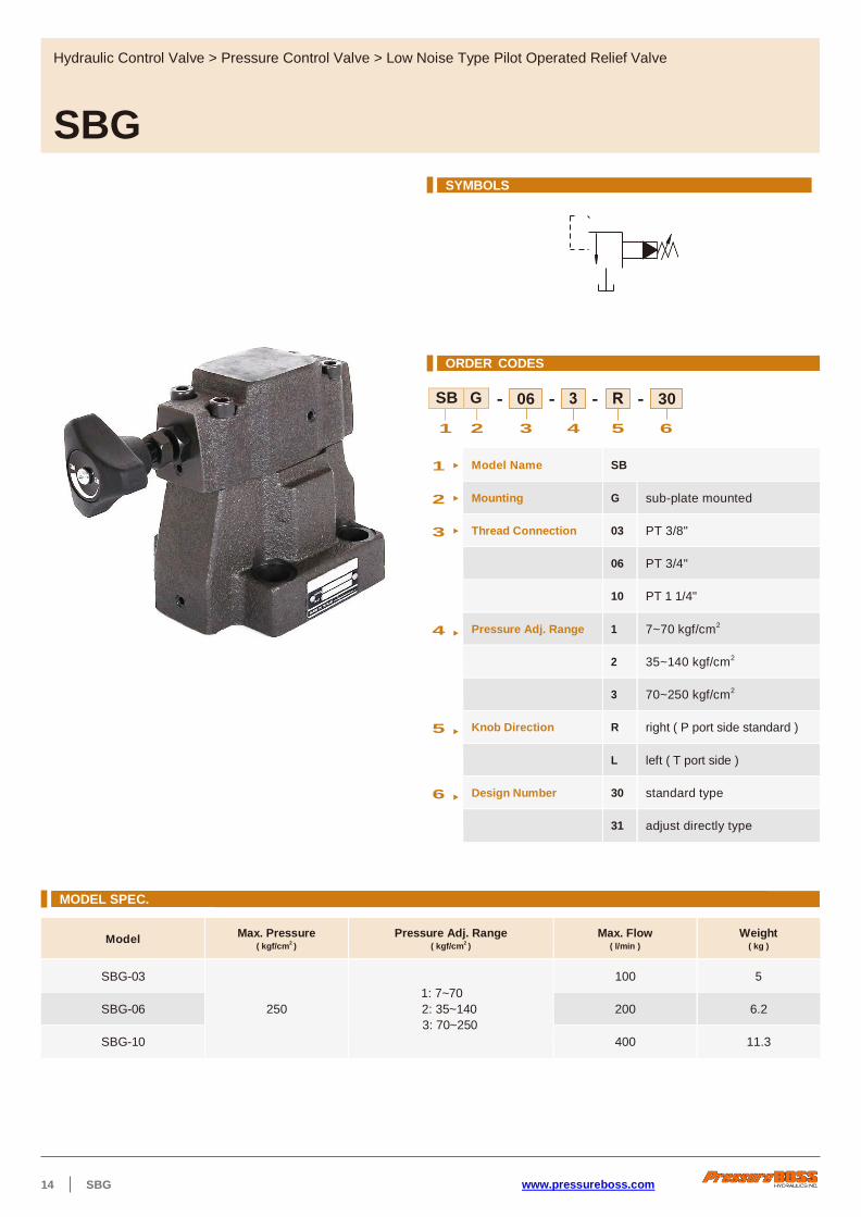
1 Model Name SB
2 Mounting G sub-plate mounted
3 Thread Connection 03 PT 3/8"
06 PT 3/4"
10 PT 1 1/4"
4 Pressure Adj. Range 1 7~70 kgf/cm2
2 35~140 kgf/cm2
3 70~250 kgf/cm2
5 Knob Direction R right ( P port side standard )
L left ( T port side )
6 Design Number 30 standard type
31 adjust directly type
Model Max. Pressure
( kgf/cm2 )
Pressure Adj. Range ( kgf/cm
2 )
Max. Flow ( l/min )
Weight ( kg )
SBG-03
250
1: 7~70
2: 35~140
3: 70~250
100 5
SBG-06 200 6.2
SBG-10 400 11.3
Hydraulic Control Valve > Pressure Control Valve > Low Noise Type Pilot Operated Relief Valve
SBG
MODEL SPEC.
30 SB G

DIMENSION ( UNIT : mm )
www.pressureboss.com SBG 15
Max. F E
Gauge Port G
Vent Port
P Port
ØK Depth 1
Tank Port
SBG-R, L
Max. H
SBG-R
Model A B C D E F G H J K L N P Q S
SBG-03 76 53.8 11.1 26.9 53.8 113.5 22 171 13.5 21 51 132 104 22 106
SBG-06 104 70 17 35 66.7 98.8 27 171 17.5 25 51 132 104 27 123
SBG-10 120 82.6 18.7 41.3 88.9 58.6 33.5 188 21.5 32 65 167 135 33.5 155
SBG-L
L
N
P
Q
D
B
C
A
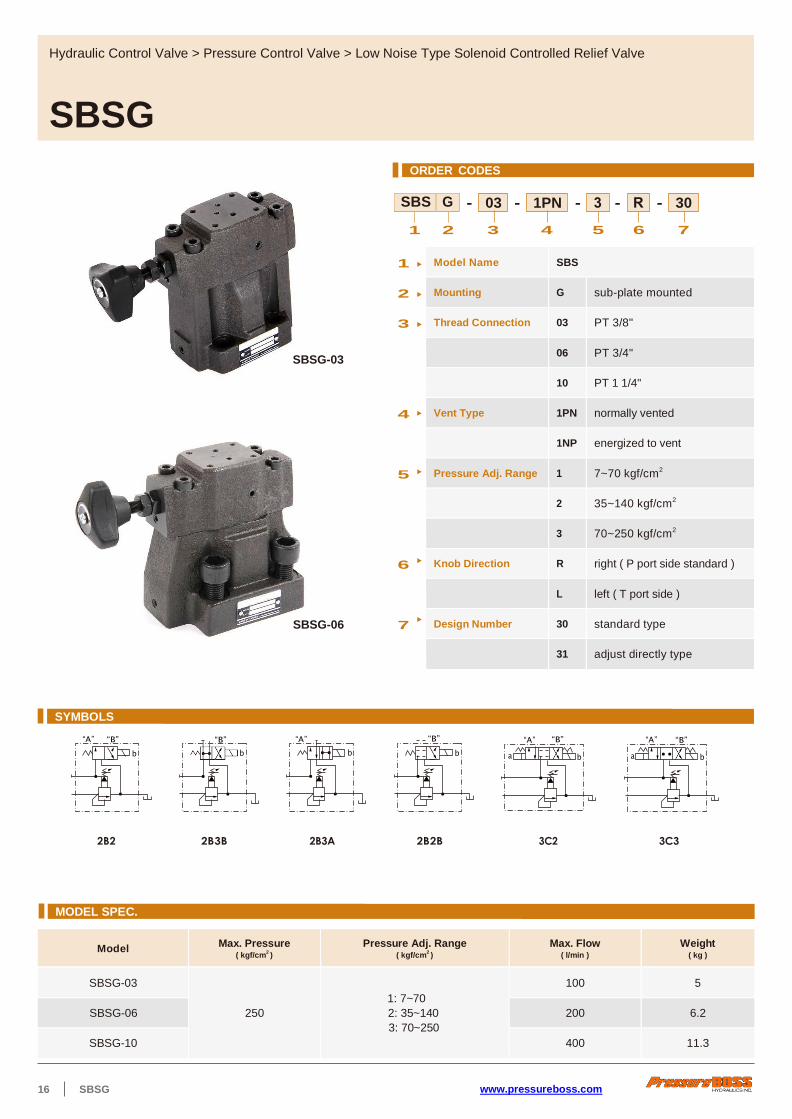
16 SBSG www.pressureboss.com
1PN 03
ORDER CODES
- - - - -
1 2 3 4 5 6 7
SBSG-03
SBSG-06
“A” “B”
b
“B”
b
“A”
b
“B”
b
“A”
a
“B”
b
“A”
a
“B”
b
2B2 2B3B 2B3A 2B2B 3C2 3C3
Model Max. Pressure
( kgf/cm2 )
Pressure Adj. Range ( kgf/cm
2 )
Max. Flow ( l/min )
Weight ( kg )
SBSG-03
250
1: 7~70
2: 35~140
3: 70~250
100 5
SBSG-06 200 6.2
SBSG-10 400 11.3
Hydraulic Control Valve > Pressure Control Valve > Low Noise Type Solenoid Controlled Relief Valve
SBSG
MODEL SPEC.
SYMBOLS
30 SBS G
1 Model Name SBS
2 Mounting G sub-plate mounted
3 Thread Connection 03 PT 3/8"
06 PT 3/4"
10 PT 1 1/4"
4 Vent Type 1PN normally vented
1NP energized to vent
5 Pressure Adj. Range 1 7~70 kgf/cm2
2 35~140 kgf/cm2
3 70~250 kgf/cm2
6 Knob Direction R right ( P port side standard )
L left ( T port side )
7 Design Number 30 standard type
31 adjust directly type

DIMENSION ( UNIT : mm )
www.pressureboss.com SBSG 17
SBSG-R
Max. H
Max. F E
Gauge Port G
Vent Port
P Port
Tank Port
4 - ØJ
ØK Depth 1
Model A B C D E F G H J K L N Q S T U V
SBSG-03 76 53.8 11.1 26.9 53.8 96 27 180 13.5 21 48 219 156 132 104 22 106
SBSG-06 104 70 17 35 66.7 98.8 33.7 180 17.5 25 48 219 156 132 104 27 123
SBSG-10 120 82.6 18.7 41.3 88.9 100 44.9 182 21.5 32 65 232 169 145 135 33.5 155
A P B
N
Q
S
T
U
87
D
B
C
A
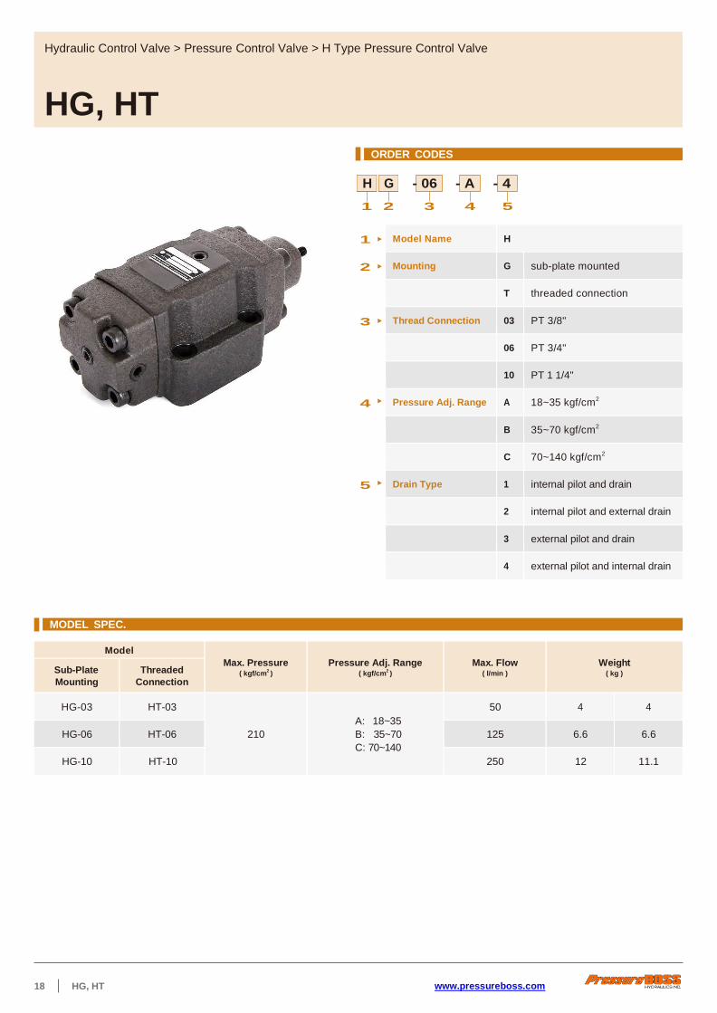
18 HG, HT www.pressureboss.com
ORDER CODES
H G - 06 - A - 4
1 2 3 4 5
MODEL SPEC.
Model
Max. Pressure ( kgf/cm
2 )
Pressure Adj. Range ( kgf/cm
2 )
Max. Flow ( l/min )
Weight ( kg ) Sub-Plate
Mounting
Threaded
Connection
HG-03 HT-03
210
A: 18~35
B: 35~70
C: 70~140
50 4 4
HG-06 HT-06 125 6.6 6.6
HG-10 HT-10 250 12 11.1
Hydraulic Control Valve > Pressure Control Valve > H Type Pressure Control Valve
HG, HT
1 Model Name H
2 Mounting G sub-plate mounted
T threaded connection
3 Thread Connection 03 PT 3/8"
06 PT 3/4"
10 PT 1 1/4"
4 Pressure Adj. Range A 18~35 kgf/cm2
B 35~70 kgf/cm2
C 70~140 kgf/cm2
5 Drain Type 1 internal pilot and drain
2 internal pilot and external drain
3 external pilot and drain
4 external pilot and internal drain

www.pressureboss.com HG, HT 19
SYMBOLS
Valve Type Type 1.
Low Pressure Relief Valve
Type 2.
Sequence Valve
Type 3.
Sequence Valve
Type 4.
Unloading Valve
Pilot-Drain Type Internal Pilot-Internal Drain Internal Pilot-Internal Drain Internal Pilot-External Drain External Pilot-External Drain
Operations
Symbols
1
8
With auxiliary
pilot port
1
8
With auxiliary
pilot port
1
8
With auxiliary
pilot port
HT-03, 06, 10
A
B Pressure Adj. Screw 10 Hex.
Lock Nut
13 Hex.
Drain Port
PT 1/4"
P2 Port
PT "Q"
P1 Gauge Port
PT 1/4"
P2 Gauge Port
PT 1/4"
2 - P1 Port
PT "Q"
Model A B C D E F G H J K L N Q
HT-03 42 84 61 74 195 57 106 43 70 0 28 28 3/8”
HT-06 48 96 73 86 219 64.5 123.5 50.5 80 9 33 42 3/4”
HT-10 68.5 137 84 103 272 84 149 66 98 12 40 52 1 1/4"
DIMENSION ( UNIT : mm )
C
A
K
L
D
H
J
F
G
Ma
x. E
N

20 HG, HT www.pressureboss.com
HG-03, 06
Pressure Adj. Screw
10 Hex.
Lock Nut
13 Hex.
HG-10
Pressure Adj. Screw
10 Hex.
Lock Nut
13 Hex.
60 67 61 39 89 195 170.3 52.3
73 81 73 39 102 219 192 51
Drain Port P2 Port
Ø17.5 Depth 1
External Pilot
Port X
P1 Port
P2 Port
Drain Port
Ø17.5 Depth 1
External Pilot
Port X
P1 Port
119
DIMENSION ( UNIT : mm )
B
F
92
27
2
C
4
6
G
D
23
3
H
4
3
6
2
A
86

www.pressureboss.com HCG, HCT 21
06
ORDER CODES
- - -
1 2 3 4 5
Model
Max. Pressure ( kgf/cm
2 )
Pressure Adj. Range ( kgf/cm
2 )
Max. Flow ( l/min )
Weight ( kg ) Sub-Plate
Mounting
Threaded
Connection
HCG-03 HCT-03
210
A: 18~35
B: 35~70
C: 70~140
50 5 4
HCG-06 HCT-06 125 8 7.5
HCG-10 HCT-10 250 13 14
Hydraulic Control Valve > Pressure Control Valve > HC Type Pressure Control Valve
HCG, HCT
1 Model Name HC
2 Mounting G sub-plate mounted
T threaded connection
3 Thread Connection 03 PT 3/8"
06 PT 3/4"
10 PT 1 1/4"
4 Pressure Adj. Range A 18~35 kgf/cm2
B 35~70 kgf/cm2
C 70~140 kgf/cm2
5 Drain Type 1 internal pilot and drain
2 internal pilot and external drain
3 external pilot and drain
4 external pilot and internal drain
MODEL SPEC.
HC G
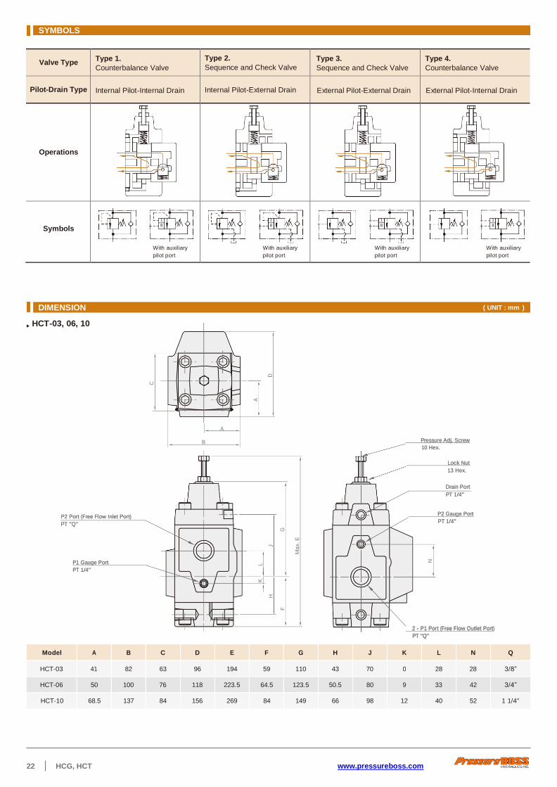
22 HCG, HCT www.pressureboss.com
SYMBOLS
Valve Type Type 1.
Counterbalance Valve
Type 2.
Sequence and Check Valve
Type 3.
Sequence and Check Valve
Type 4.
Counterbalance Valve
Pilot-Drain Type Internal Pilot-Internal Drain Internal Pilot-External Drain External Pilot-External Drain External Pilot-Internal Drain
Operations
Symbols
1
8
With auxiliary
pilot port
1
8
With auxiliary
pilot port
1
8
With auxiliary
pilot port
1
8
With auxiliary
pilot port
HCT-03, 06, 10
A
B PPrreessssuurree AAddjj.. SSccrreeww
1100 HHeexx..
LLoocckk NNuutt
1133 HHeexx..
DDrraaiinn PPoorrtt
PPTT 11//44""
PP22 PPoorrtt ((FFrreeee FFllooww IInnlleett PPoorrtt))
PPTT ""QQ""
PP11 GGaauuggee PPoorrtt
PPTT 11//44""
PP22 GGaauuggee PPoorrtt
PPTT 11//44""
22 -- PP11 PPoorrtt ((FFrreeee FFllooww OOuuttlleett PPoorrtt))
PPTT ""QQ""
Model A B C D E F G H J K L N Q
HCT-03 41 82 63 96 194 59 110 43 70 0 28 28 3/8”
HCT-06 50 100 76 118 223.5 64.5 123.5 50.5 80 9 33 42 3/4”
HCT-10 68.5 137 84 156 269 84 149 66 98 12 40 52 1 1/4"
DIMENSION ( UNIT : mm )
C
A
K
L
D
H
J
F
G
Ma
x. E
N

DIMENSION ( UNIT : mm )
www.pressureboss.com HCG, HCT 23
HCG-03, 06
Pressure Adj. Screw
10 Hex.
Lock Nut
13 Hex.
Drain Port
P2 Port
(Free Flow Inlet Port)
6 - Ø11
Ø17.5 Depth 1
External Pilot
Port X
P1 Port E (Free Flow Outlet Port)
HCG-10
Pressure Adj. Screw
10 Hex.
Lock Nut
13 Hex.
HCG-03 87 59 35 60 89 191 170 54
HCG-06 108 69 40 73 102 221 188 51
P2 Port
(Free Flow Inlet Port)
Drain Port
Ø17.5 Depth 1
External Pilot
Port X
P1 Port
(Free Flow Outlet Port)
119
13
2
F
27
2
A
B
C
79
G
23
3
46
H
6
2
D
98

24 RG, RT www.pressureboss.com
SYMBOLS
ORDER CODES
R G - 03 - 1 - 31
1 2 3 4 5
1 Model Name R
2 Mounting G sub-plate mounted
T threaded connection
3 Thread Connection 03 PT 3/8"
06 PT 3/4"
10 PT 1 1/4"
4 Pressure Adj. Range 1 7~70 kgf/cm2
2 35~140 kgf/cm2
3 70~250 kgf/cm2
5 Design Number 30 standard type
31 adjust directly type
Model
Max. Pressure ( kgf/cm
2 )
Pressure Adj. Range ( kgf/cm
2 )
Rated Flow ( l/min )
Weight ( kg ) Sub-Plate
Mounting
Threaded
Connection
RG-03 RT-03
250
1: 7~70
2: 35~140
3: 70~250
50 4.3 4.6
RG-06 RT-06 125 7.4 7.2
RG-10 RT-10 250 12 11
Hydraulic Control Valve > Pressure Control Valve > Pressure Reducing Valve
RG, RT
MODEL SPEC.
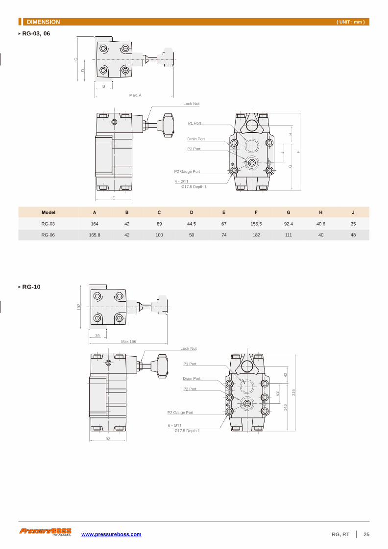
DIMENSION ( UNIT : mm )
www.pressureboss.com RG, RT 25
P1 Port
Drain Port
P2 Port
P2 Gauge Port
Ø17.5 Depth 1
92
RG-03, 06
Lock Nut
RG-10
Lock Nut
RG-03 164 42 89 44.5 67 155.5 92.4 40.6 35
RG-06 165.8 42 100 50 74 182 111 40 48
P1 Port
Drain Port
P2 Port
P2 Gauge Port
Ø17.5 Depth 1
Max. A
39
Max.166
C
D
19
2
63
J
14
6
42
G
H
21
6
F
DIMENSION ( UNIT : mm )
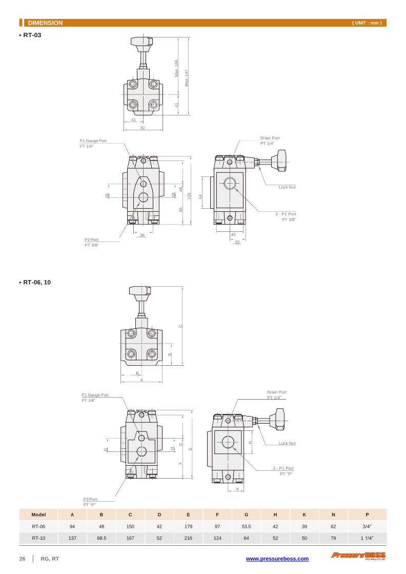
26 RG, RT www.pressureboss.com
RT-03
P1 Gauge Port
PT 1/4"
41
82
Drain Port
PT 1/4"
Lock Nut
2 - P1 Port
PT 3/8"
P2 Port
PT 3/8"
36 40
32
RT-06, 10
B
A
P1 Gauge Port
PT 1/4"
Drain Port
PT 1/4"
Lock Nut
2 - P1 Port
PT "P"
K
P2 Port
PT "P"
Model A B C D E F G H K N P
RT-06 94 48 150 42 179 97 53.5 42 39 62 3/4”
RT-10 137 68.5 167 52 216 124 64 52 50 79 1 1/4”
D
2
8
B
H
F
G
E
28
85
48
15
5
41
M
ax.
10
6
C
Ma
x.
14
7
44
N

www.pressureboss.com RCG, RCT 27
SYMBOLS
ORDER CODES
RC G - 03 - 1 - 31
1 2 3 4 5
1 Model Name RC
2 Mounting G sub-plate mounted
T threaded connection
3 Thread Connection 03 PT 3/8"
06 PT 3/4"
10 PT 1 1/4"
4 Pressure Adj. Range 1 7~70 kgf/cm2
2 35~140 kgf/cm2
3 70~250 kgf/cm2
5 Design Number 30 standard type
31 adjust directly type
Model
Max. Pressure ( kgf/cm
2 )
Pressure Adj. Range ( kgf/cm
2 )
Rated Flow ( l/min )
Weight ( kg ) Sub-Plate
Mounting
Threaded
Connection
RCG-03 RCT-03
250
1: 7~70
2: 35~140
3: 70~250
50 4.5 5.5
RCG-06 RCT-06 125 7.8 8.3
RCG-10 RCT-10 250 14.4 13.4
Hydraulic Control Valve > Pressure Control Valve > Pressure Reducing and Check Valve
RCG, RCT
MODEL SPEC.

28 RCG, RCT www.pressureboss.com
DIMENSION ( UNIT : mm )
Max. A
P1 Port
Drain Port
P2 Port
P2 Gauge Port
Ø17.5 Depth 1
P1 Port
Drain Port
P2 Port
P2 Gauge Port
Ø17.5 Depth 1
132
RCG-03, 06 K
Lock Nut
RCG-10
Lock Nut
RCG-03 164 61 90 45 88 155 92.4 45 34.9 25
RCG-06 164 70 104 52 109 182 111 40 48 21.5
27.5
79
Max.166
11
9
59
.5
C
D
J
G
H
63
F
14
6
42
21
6
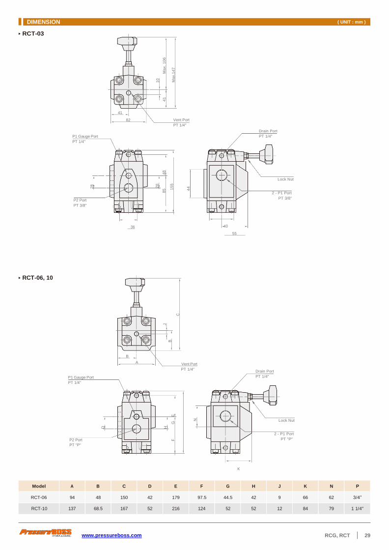
www.pressureboss.com RCG, RCT 29
DIMENSION ( UNIT : mm )
RCT-03
P1 Gauge Port
PT 1/4"
41
82 Vent Port
PT 1/4"
Drain Port
PT 1/4"
Lock Nut
P2 Port
PT 3/8"
2 - P1 Port
PT 3/8"
36 40
55
RCT-06, 10
P1 Gauge Port
PT 1/4"
B
A Vent Port
PT 1/4" Drain Port
PT 1/4"
Lock Nut
P2 Port
PT "P"
2 - P1 Port
PT "P"
K
Model A B C D E F G H J K N P
RCT-06 94 48 150 42 179 97.5 44.5 42 9 66 62 3/4”
RCT-10 137 68.5 167 52 216 124 52 52 12 84 79 1 1/4"
28
D
28
85
48
15
5
1
0
4
1
Ma
x.
10
6
J
B
H
F
G
E
Ma
x.1
47
C
44
N

30 SRG, SRT www.pressureboss.com
SYMBOLS
ORDER CODES
-
1 2 3
1 Model Name SR
2 Mounting G sub-plate mounted
T threaded connection
3 Thread Connection 03 PT 3/8"
06 PT 3/4"
10 PT 1 1/4"
Model
Max. Pressure ( kgf/cm
2 )
Rated Flow ( l/min )
Weight ( kg ) Sub-Plate
Mounting
Threaded
Connection
SRG-03 SRT-03
250
30 1.1 1.2
SRG-06 SRT-06 80 2.3 2.3
SRG-10 SRT-10 200 5.5 5.2
Hydraulic Control Valve > Flow Control Valve > Throttle Valve
SRG, SRT
MODEL SPEC.
SR G 03

www.pressureboss.com SRG, SRT 31
DIMENSION ( UNIT : mm )
SRG
Max. L
N
P
Control Flow Outlet Port
Adj. Screw
A
B D 4 - ØT Hole
C ØU Depth V
Lock Nut
S Hex.
Control Flow Inlet Port
SRT A
B
ØC
Adj. Screw
Lock Nut
L Hex.
Control Flow Inlet Port
PT "N" Control Flow Outlet Port
PT "N"
Model A B C D E F G H J L N
SRT-03 70 35 40 143 54 23 42 20 40 19 3/8”
SRT-06 100 50 40 136.5 62 30 62 30 60 19 3/4”
SRT-10 130 65 56 173 73 40 82 40 80 22 1 1/4"
P Q T
SRT-03 60 40 20 10 80 60 30 10 45 15 100 65 30 44 19 14 8.6
SRT-06 80 58 29 11 92 70 35 11 54 16 117.5 73 42 41.5 23 11 17.5 10.8
SRT-10 100 72 36 14 120 92 46 14 71 21 145 100 55 56 23 13.5 21
H
G
ØQ
F
E
Ma
x. D
E
J
K
G
J
H
F

32 SRCG, SRCT www.pressureboss.com
SYMBOLS
IN OUT
ORDER CODES
-
1 2 3
1 Model Name SRC
2 Mounting G sub-plate mounted
T threaded connection
3 Thread Connection 03 PT 3/8"
06 PT 3/4"
10 PT 1 1/4"
MODEL SPEC.
Model
Max. Pressure ( kgf/cm
2 )
Rated Flow ( l/min )
Weight ( kg ) Sub-Plate
Mounting
Threaded
Connection
SRCG-03 SRCT-03
250
30 1.4 1.8
SRCG-06 SRCT-06 80 3.5 4.0
SRCG-10 SRCT-10 200 7.2 8.1
Hydraulic Control Valve > Flow Control Valve > Throttle and Check Valve
SRCG, SRCT
SRC G 03

www.pressureboss.com SRCG, SRCT 33
DIMENSION ( UNIT : mm )
B D
C
Control Flow Outlet Port or
Free Flow Inlet Port
4 - ØU Hole
ØV Depth W
Control Flow Inlet Port or
Free Flow Outlet Port
R
Adj. Screw
Lock Nut
T Hex.
Q
SRCG A
P
SRCT
Model A B C D E F G H J L N
SRCT-03 70 35 40 180 62.5 58 42 21 40 19 3/8”
SRCT-06 100 50 60 215 83 65 62 31 60 19 3/4”
SRCT-10 130 65 80 228 106 77 82 41 80 22 1 1/4"
P Q T W
SRCG-03 60 40 20 10 179 80 60 30 28 10 45 15 62 55 35 19 8.8 14 8.6
SRCG-06 80 58 29 11 213 95 70 35 30 11 54 16 74 68 40 19 11 17.5 10.8
SRCG-10 100 72 36 14 228 120 92 46 31 14 71 21 97 82 50 22 13.5 21
Adj. Screw
Lock Nut
L Hex.
Control Flow Outlet Port or
Free Flow Inlet Port
ØC
Control Flow Inlet Port or
Free Flow Outlet Port
H
F
E
Ma
x. D
L
N
K H
J
G
F
J
Ma
x. E
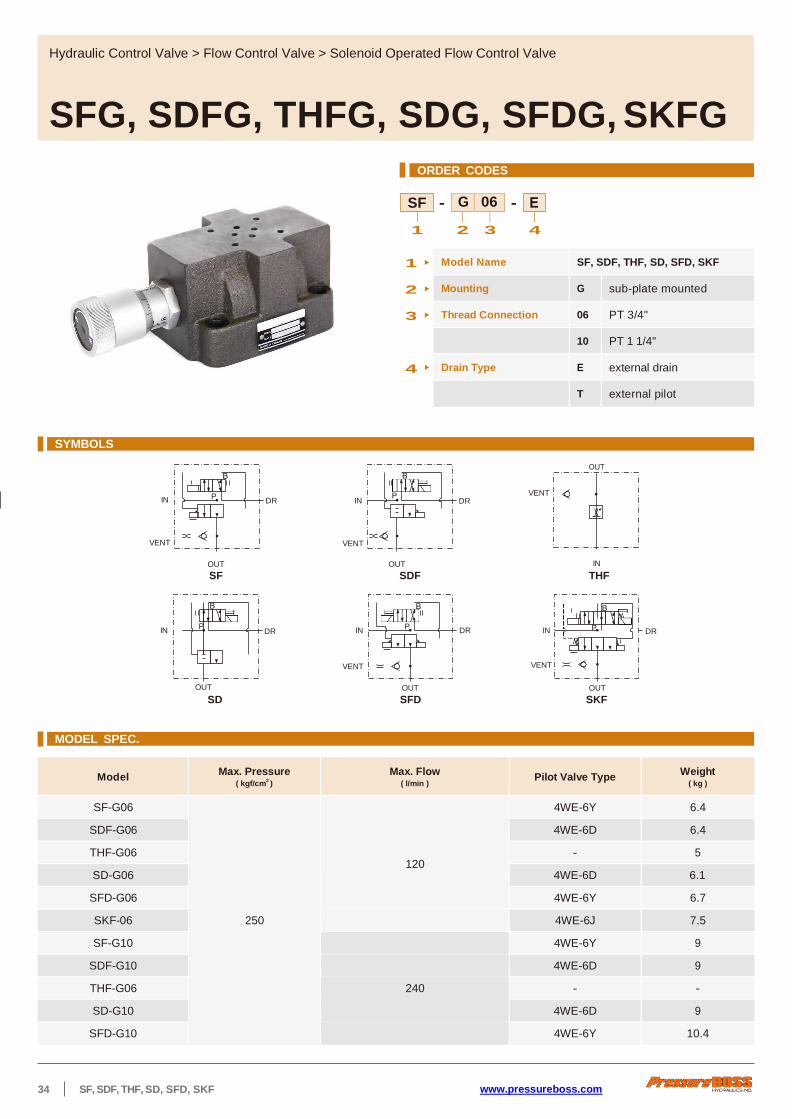
34 SF, SDF, THF, SD, SFD, SKF www.pressureboss.com
ORDER CODES
- -
1 2 3 4
1 Model Name SF, SDF, THF, SD, SFD, SKF
2 Mounting G sub-plate mounted
3 Thread Connection 06 PT 3/4"
10 PT 1 1/4"
4 Drain Type E external drain
T external pilot
SYMBOLS
OUT
IN DR IN VENT
DR
VENT VENT
OUT OUT IN
SF SDF THF
IN DR IN DR IN DR
VENT VENT
OUT OUT OUT
SD SFD SKF
MODEL SPEC.
Model Max. Pressure
( kgf/cm2 )
Max. Flow ( l/min )
Pilot Valve Type Weight
( kg )
SF-G06
250
120
4WE-6Y 6.4
SDF-G06 4WE-6D 6.4
THF-G06 - 5
SD-G06 4WE-6D 6.1
SFD-G06 4WE-6Y 6.7
SKF-06 4WE-6J 7.5
SF-G10 4WE-6Y 9
SDF-G10 4WE-6D 9
THF-G06 240 - -
SD-G10 4WE-6D 9
SFD-G10 4WE-6Y 10.4
Hydraulic Control Valve > Flow Control Valve > Solenoid Operated Flow Control Valve
SFG, SDFG, THFG, SDG, SFDG, SKFG
SF G 06

www.pressureboss.com SF, SDF, THF, SD, SFD, SKF 35
DIMENSION ( UNIT : mm )
SF-G
Outlet Port
J
I
H
G
F E Drain Port
Max. D
Vent Port
Inlet Port
K
Model A B C D E F G H I J K L M N Q R S
SF-G06 35 75 160 209 17.5 26 40.5 64 90 125 31.7 10.5 9.5 37 63 74 95
SF-G10 40 85 171 248 19 34 47 78 112 150 37.9 14.5 16 43 76 86 115
SDF-G
Outlet Port
J
I Drain Port
H
G
F E
Max. D
Vent Port
Inlet Port
K
THF-G J Outlet Port
ØC I
H
F E
Max. D
Vent Port K Ø1
Inlet Port
ØC
Model A B C D E F H I J K L N Q R S
THF-G06 35 75 Ø26 209 17.5 26 64 90 125 31.7 10.5 37 63 74 95
THF-G10 40 86 Ø29 248 19 34 78 112 150 37.9 14.5 43 76 86 115
Model A B C D E F G H I J K L M N Q R S
SDF-G10 40 86 171 248 19 34 47 78 112 150 37.9 14.5 16 43 76 86 115
95 74 63 37 9.5 10.5 31.7 125 90 64 40.5 26 17.5 209 160 75 35 SDF-G06
A P B
C
B
A
B
A
A
B
C
S
R
Q
N
L
S
R
Q
N
M L
S
R
Q
N
M L

36 SF, SDF, THF, SD, SFD, SKF www.pressureboss.com
SD-G
Outlet Port
J
I
H
G
F E Drain Port
Inlet Port
Model A B C D E F G H I J L M N R S
SD-G06 35 75 160 180 17.5 26 40.5 64 90 125 10.5 9.5 37 74 95
SD-G10 40 86 171 197 19 34 47 78 112 150 14.5 16 43 86 115
SFD-G J
I
Outlet Port H
G
F E Drain Port
Inlet Port
Max. D
Vent Port K
Model A B C D E F G H I J K L M N Q R S
SFD-G06 35 75 160 277 17.5 26 40.5 64 90 125 31.7 10.5 9.5 37 63 74 95
SFD-G10 40 86 171 328 19 34 47 78 112 150 37.9 14.5 16 43 76 86 115
SKF
Outlet Port
J
I
H
G
F E Drain Port
Inlet Port
T
Max. D Vent Port K
Model A B C D E F G H I J K L M N Q R S T
SKF-G06 35 75 160 315 17.5 26 40.5 64 90 125 31.7 10.5 9.5 37 63 74 95 27
DIMENSION ( UNIT : mm )
A P B
A P B
C
C
B
A
B
A
C
B
A
S
R
N
S
R
M L
Q
N
M
S
R
Q
N
M L
L

www.pressureboss.com CRG 37
03
SYMBOLS
ORDER CODES
- -
1 2 3 4
1 Model Name CR
2 Mounting G sub-plate mounted
3 Thread Connection 03 PT 3/8"
06 PT 3/4"
10 PT 1 1/4"
4 Cracking Pressure 05 0.35 kgf/cm2
50 3.5 kgf/cm2
75 5 kgf/cm2
MODEL SPEC.
Model Max. Pressure
( kgf/cm2 )
Cracking Pressure ( kgf/cm
2 )
Rated Flow ( l/min )
Weight ( kg )
CRG-03
250
05: 0.35
50: 3.5
75: 5
40 2
CRG-06 125 4.4
CRG-10 250 8
CRG K
Model A B C D E F G H J K L N P Q R
CRG-03 68 47.6 23.8 47.6 30.1 12.7 80 60.3 10 70 36 46 11 17.5 10.2
CRG-06 101 65.2 32.6 68.2 40.5 22.2 114 80.9 16.5 81 38 54 17.5 26 16.45
CRG-10 130 92.1 46.1 71.4 46 20.6 130 92.1 19 100 50 67 21.5 30 18.95
Hydraulic Control Valve > Directional Control Valve > Check Valve
CRG
DIMENSION ( UNIT : mm )
B
ØQ Depth 1
Inlet Port
Outlet Port
05 CR
D
E
F
H
J
G

38 CPG, CPT, CPDG, CPDT www.pressureboss.com
05 03
SYMBOLS
OUT OUT
DR IN
P.P P.P
IN
ORDER CODES
- - - -
1 2 3 4 5 6
1 Model Name CP pilot controlled check
valve
CPD decompression type pilot
controlled check valve
2 Mounting G sub-plate mounted
T threaded connection
3 Thread Connection 03 PT 3/8"
06 PT 3/4"
10 PT 1 1/4"
4 Cracking Pressure 05 0.35 kgf/cm2
50 3.5 kgf/cm2
5 Drain and Pilot
Connection E
external pilot & internal
drain
ET external pilot & external
drain
6 Design Number 10 non ISO mounting
20 ISO mounting
Model
Max. Pressure ( kgf/cm
2 )
Cracking Pressure ( kgf/cm
2 )
Rated Flow ( l/min )
Weight ( kg ) Sub-Plate
Mounting
Threaded
Connection
CPG-03
CPDG-03
CPT-03
CPDT-03
250 05: 0.35
50: 3.5
40 4.0 5.0
CPG-06
CPDG-06
CPT-06
CPDT-06 125 6.0 6.5
CPG-10
CPDG-10
CPT-10
CPDT-10 250 11.5 12.0
Hydraulic Control Valve > Directional Control Valve > Pilot Operated Check Valve
CPG, CPT, CPDG, CPDT
MODEL SPEC.
10 CPD
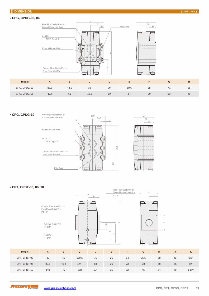
www.pressureboss.com CPG, CPT, CPDG, CPDT 39
Free Flow Outlet Port or
Control Flow Inlet Port Pilot Port
Ø17.5 Depth 1
External Drain Port
Control Flow Outlet Port or
Free Flow Inlet Port
B
CPG, CPDG-03, 06 A F
G H
CPG, CPDG-10 93
79
46
CPT, CPDT-03, 06, 10 Free Flow Inlet Port or Control Flow Outlet Port
A PT "K"
Control Flow Inlet Port or
Free Flow Outlet Port
PT "K"
External Drain Port
PT 1/4"
Pilot Port
PT 1/4"
Model A B C D E F G H J K
CPT, CPDT-03 80 40 150.5 75 21 64 35.5 58 41 3/8”
CPT, CPDT-06 99.6 49.8 174 84 26 73 38 68 65 3/4”
CPT, CPDT-10 140 70 208 104 35 92 45 84 79 1 1/4"
CPG, CPDG-03 87.5 44.5 10 144 50.6 68 41 35
CPG, CPDG-06 102 51 11.3 174 57 80 50 40
Free Flow Outlet Port or
Control Flow Inlet Port 119
59.5 11.1
External Drain Port
Ø17 Depth 7
Control Flow Outlet Port or
Free Flow Inlet Port
Pilot Port
F
DIMENSION ( UNIT : mm )
E
H
D
E
D
62
21
0
C
J

40 DHG www.pressureboss.com
AB ET 3C2 04
ORDER CODES
- - - - -
1 2 3 4 5 6 7
DHG-06
Model Max. Flow
( l/min )
Max. Operational
Pressure ( kgf/cm
2 )
Max. Pilot
Pressure ( kgf/cm
2 )
Min. Pilot
Pressure ( kgf/cm
2 )
Max. Pressure ( kgf/cm
2 )
Max. Change Over
Frequency ( cycles/min )Weight
( kg ) EXT.
Drain
INT.
Drain AC DC
DHG-04 300 315 250 8 210 140 120 120 6.1
DHG-06 500 315 250 8 210 140 120 120 12.0
Hydraulic Control Valve > Directional Control Valve > Pilot Operated Directional Valve
DHG
MODEL SPEC.
DH G
1 Model Name DH
2 Mounting G sub-plate mounted
3 Thread Connection 04 PT 1/2"
06 PT 3/4"
4 Spool Type please refer to the symbol list
5 Drain Type none pilot oil supply internal,
pilot oil drain internal
T pilot oil supply internal,
pilot oil drain external
ET pilot oil supply external,
pilot oil drain external
E pilot oil supply external,
pilot oil drain internal
6 Adjustable Stroke AB both side with adjustable
strokes
A port A side with adjustable
stroke
B port B side with adjustable
stroke
7 Knob none without knob
K with knob
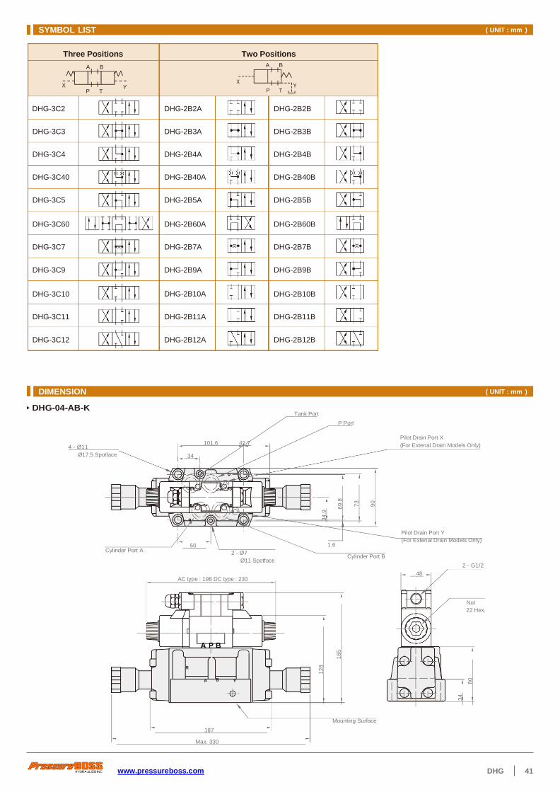
www.pressureboss.com DHG 41
DHG-04-AB-K Tank Port
P Port
4 - Ø11
Ø17.5 Spotface
101.6 42.7
34
Pilot Drain Port X
(For Extenal Drain Models Only)
Cylinder Port A 50
2 - Ø7
Ø11 Spotface
1.6
Cylinder Port B
Pilot Drain Port Y
(For Extenal Drain Models Only)
2 - G1/2
AC type : 198 DC type : 230 48
Nut
22 Hex.
Y
Mounting Surface
187
Max. 330
SYMBOL LIST ( UNIT : mm )
A B A B
DHG-3C3 DHG-2B3A DHG-2B3B
DHG-3C4 DHG-2B4A DHG-2B4B
DHG-3C40 DHG-2B40A DHG-2B40B
DHG-3C5 DHG-2B5A DHG-2B5B
DHG-3C60 DHG-2B60A DHG-2B60B
DHG-3C7 DHG-2B7A DHG-2B7B
DHG-3C9 DHG-2B9A DHG-2B9B
DHG-3C10 DHG-2B10A DHG-2B10B
DHG-3C11 DHG-2B11A DHG-2B11B
DHG-3C12 DHG-2B12A DHG-2B12B
Three Positions Two Positions
X X
DHG-3C2 DHG-2B2A DHG-2B2B
DIMENSION ( UNIT : mm )
A P B
R
B A
Y T P
Y T P
12
8
34
.9
16
5
69
.8
73
90
3
4
80

42 DHG www.pressureboss.com
DHG-04
4 - Ø11
Ø17.5 Spotface
101.6 42.7
34
Tank Port P Port
Pilot Drain Port X
(For Extenal Drain Models Only)
Cylinder Port A 50
2 - Ø7
Ø11 Spotface
1.6
Cylinder Port B
Pilot Drain Port Y
(For Extenal Drain Models Only)
2 - G1/2
AC type : 198 DC type : 230 48
Nut
22 Hex.
A P B
Mounting Surface 187
DHG-06-AB-K Cylinder Port B
77
Cylinder Port A
Pilot Pressure Port X
6 - Ø13.5
Ø20 Spotface
Pilot Drain Port Y
P Port
P T
53.2 Tank Port
130.2
AC type : 198 DC type : 230
50
48
2 - G1/2
Nut
22 Hex.
PT 1/8"
A P B
Mounting Surface 186
DIMENSION ( UNIT : mm )
R
A B Y
Y
XB
A
19
9
16
2
34
.9
12
8
69
.8
16
5
73
90
4
6
92
11
8
3
4
80
42
11
4


www.pressureboss.com DHG 43
77 Pilot Pressure Port X
Ø20 Spotface
Pilot Drain Port Y Tank Port
53.2 P Port
130.2 50
AC type : 198 DC type : 230 48
Nut
22 Hex.
A P B
Mounting Surface 186
256
DHG-06 Cylinder Port B
Cylinder Port A
DIMENSION ( UNIT : mm )
XB
A
19
9
16
2
4
6
92
11
8
42
11
4
Pressure Boss Hydraulics Inc.
1352 County Road 2630
Mount Pleasant, TX 75455
Tel : +936-224-2080
Email : [email protected]
© Pressure Boss Hydraulics Inc. All rights reserved.
* We reserve the right to make changes without notice
in the course of continued development.