Hydraulic artificial muscles - MIT CSAIL
12
Article Journal of Intelligent Material Systems and Structures 23(3) 301–312 Ó The Author(s) 2012 Reprints and permissions: sagepub.co.uk/journalsPermissions.nav DOI: 10.1177/1045389X12438627 jim.sagepub.com Hydraulic artificial muscles Rashi Tiwari*, Michael A Meller*, Karl B Wajcs, Caris Moses, Ismael Reveles and Ephrahim Garcia Abstract This article presents hydraulic artificial muscles as a viable alternative to pneumatic artificial muscles. Despite the actua- tion mechanism being similar to its pneumatic counterpart, hydraulic artificial muscles have not been widely studied. Hydraulic artificial muscles offer all the same advantages of pneumatic artificial muscles, such as compliance, light weight, low maintenance, and low cost, when compared to traditional fluidic cylinder actuators. Muscle characterization in isometric and isobaric conditions are discussed and compared to pneumatic artificial muscles. A quasi-static model incor- porating the effect of mesh angle, friction, and muscle volume change throughout actuation is presented. This article also discusses the use of hydraulic artificial muscles for low-pressure hydraulic mesoscale robotic leg. Keywords actuator, artificial muscle, mesoscale, hydraulics, antagonistic pairs, robots Introduction The McKibben artificial muscle actuator, named after its inventor Joseph L McKibben, has been commonly used in robotics systems (Chang and Lilly, 2003; Ho et al., 2000; Lilly, 2003; Noritsugu and Tanaka, 1997; Tondu et al., 2005; Vanderborght et al., 2004, 2006; Varga and Moucka, 2009; Wisse and Frankenhuyzen, 2003; Yoshinada et al., 1991), prosthetics or artificial limbs (Ferris et al., 2005; Lee and Shimoyama, 1999; Nakamura et al., 2003; Waycaster et al., 2011), and morphing (Chen et al., 2011; Kothera et al., 2010; Wereley et al., 2009; Woods et al., 2011; Yerkes and Wereley, 2008). Typically, these muscles are pneumati- cally driven, have large force-to-weight and force-to- volume ratios and are highly compliant. McKibben muscles have some analogous characteris- tics to skeletal muscle such as functionality only in tension mode, decreasing force with increasing contraction (Tondu and Lopez, 1997), and the need for an antagonis- tic pair for double-acting motion. Due to their resem- blance to biological muscles and pneumatic operation, they are commonly referred as pneumatic artificial mus- cles (PAMs). Traditionally, PAMs are composed of an inner elasto- meric tube, an outer helically wound braided sleeve, one fluid plug, one fluid port, and tube clamps to hold the other components together. When pressurized fluid is supplied through the fluid port, it causes the inner blad- der of the artificial muscle to expand radially. Normally, the inner tube would want to expand axially as well, but there is a pretensioning of the inner tube involved in the manufacturing process that eliminates this. As the blad- der expands radially, it pushes against the outer braided sleeve. This causes the whole muscle to contract axially, or produce tension, or both (Chou and Hannaford, 1996). Various modifications of PAMs like pleated mus- cles (Daerden, 1999; Daerden and Lefeber, 2001), sleeved bladder muscles (Beullens, 1989; Winters, 1995), and netted muscles (Immega, 1986, 1987; Yarlott, 1972) have been reported in the literature (Fluidic Muscle DMSP/ MAS, n.d.; Shadow Robot Company, n.d.). The typical maximum pressure of operation has been reported to be ranging from 500 to 800 kPa. This maxi- mum pressure is limited by the strength of material and need for compliance in the muscle. The stroke of artifi- cial muscles tends to be directly dependent only on the length of the muscle. Most artificial muscles have a max- imum stroke between 25% and 40% of their maximum active length; however, some muscle variants have strokes of over 50% of their maximum length (Daerden and Lefeber, 2002). Due to highly nonlinear dynamic behavior, PAMs are difficult to control and model. Laboratory of Intelligent Machine Systems, Cornell University, Ithaca, NY, USA (* Authors with equal contribution) Corresponding author: Ephrahim Garcia, Mechanical and Aerospace Engineering, 224 Upson Hall, Cornell University, Ithaca, NY, USA. Email: [email protected]
Transcript of Hydraulic artificial muscles - MIT CSAIL

Article
Journal of Intelligent Material Systemsand Structures23(3) 301–312� The Author(s) 2012Reprints and permissions:sagepub.co.uk/journalsPermissions.navDOI: 10.1177/1045389X12438627jim.sagepub.com
Hydraulic artificial muscles
Rashi Tiwari*, Michael A Meller*, Karl B Wajcs, Caris Moses,Ismael Reveles and Ephrahim Garcia
AbstractThis article presents hydraulic artificial muscles as a viable alternative to pneumatic artificial muscles. Despite the actua-tion mechanism being similar to its pneumatic counterpart, hydraulic artificial muscles have not been widely studied.Hydraulic artificial muscles offer all the same advantages of pneumatic artificial muscles, such as compliance, light weight,low maintenance, and low cost, when compared to traditional fluidic cylinder actuators. Muscle characterization inisometric and isobaric conditions are discussed and compared to pneumatic artificial muscles. A quasi-static model incor-porating the effect of mesh angle, friction, and muscle volume change throughout actuation is presented. This article alsodiscusses the use of hydraulic artificial muscles for low-pressure hydraulic mesoscale robotic leg.
Keywordsactuator, artificial muscle, mesoscale, hydraulics, antagonistic pairs, robots
Introduction
The McKibben artificial muscle actuator, named afterits inventor Joseph L McKibben, has been commonlyused in robotics systems (Chang and Lilly, 2003; Hoet al., 2000; Lilly, 2003; Noritsugu and Tanaka, 1997;Tondu et al., 2005; Vanderborght et al., 2004, 2006;Varga and Moucka, 2009; Wisse and Frankenhuyzen,2003; Yoshinada et al., 1991), prosthetics or artificiallimbs (Ferris et al., 2005; Lee and Shimoyama, 1999;Nakamura et al., 2003; Waycaster et al., 2011), andmorphing (Chen et al., 2011; Kothera et al., 2010;Wereley et al., 2009; Woods et al., 2011; Yerkes andWereley, 2008). Typically, these muscles are pneumati-cally driven, have large force-to-weight and force-to-volume ratios and are highly compliant.
McKibben muscles have some analogous characteris-tics to skeletal muscle such as functionality only in tensionmode, decreasing force with increasing contraction(Tondu and Lopez, 1997), and the need for an antagonis-tic pair for double-acting motion. Due to their resem-blance to biological muscles and pneumatic operation,they are commonly referred as pneumatic artificial mus-cles (PAMs).
Traditionally, PAMs are composed of an inner elasto-meric tube, an outer helically wound braided sleeve, onefluid plug, one fluid port, and tube clamps to hold theother components together. When pressurized fluid issupplied through the fluid port, it causes the inner blad-der of the artificial muscle to expand radially. Normally,the inner tube would want to expand axially as well, but
there is a pretensioning of the inner tube involved in themanufacturing process that eliminates this. As the blad-der expands radially, it pushes against the outer braidedsleeve. This causes the whole muscle to contract axially,or produce tension, or both (Chou and Hannaford,1996). Various modifications of PAMs like pleated mus-cles (Daerden, 1999; Daerden and Lefeber, 2001), sleevedbladder muscles (Beullens, 1989; Winters, 1995), andnetted muscles (Immega, 1986, 1987; Yarlott, 1972) havebeen reported in the literature (Fluidic Muscle DMSP/MAS, n.d.; Shadow Robot Company, n.d.).
The typical maximum pressure of operation has beenreported to be ranging from 500 to 800 kPa. This maxi-mum pressure is limited by the strength of material andneed for compliance in the muscle. The stroke of artifi-cial muscles tends to be directly dependent only on thelength of the muscle. Most artificial muscles have a max-imum stroke between 25% and 40% of their maximumactive length; however, some muscle variants havestrokes of over 50% of their maximum length (Daerdenand Lefeber, 2002). Due to highly nonlinear dynamicbehavior, PAMs are difficult to control and model.
Laboratory of Intelligent Machine Systems, Cornell University, Ithaca, NY,
USA
(* Authors with equal contribution)
Corresponding author:
Ephrahim Garcia, Mechanical and Aerospace Engineering, 224 Upson
Hall, Cornell University, Ithaca, NY, USA.
Email: [email protected]

The research reported in this article aims to extend thecapability of traditional artificial muscles as hydraulicactuators. Though the use of PAMs with hydraulic fluidmay result in increased weight, it is expected to benefitthe research on exoskeletons (Wigging et al., 2011) andmesoscale underwater robots where the surroundingwater could be used as a reservoir. Also, the use of bulkycompressors can be avoided in hydraulic artificial mus-cles (HAMs), thus making compact design possible.Additionally, using different working fluid like water oroil could result in HAMs of different stiffness, which isspecifically beneficial for exoskeleton design and control.Focchi et al. (2010) compared the use of air and waterfor artificial muscle. They reported that stiffness increaseslinearly with the contraction of the muscle.
Characterization tests in isometric and isobaricmodes, using in-house mesoscale muscles, are reportedin this article to provide insight into the muscle’s beha-vior in quasi-static conditions. In-house muscles werefabricated for these tests. A static nonlinear model topredict muscle performance is also reported. HAMapplication in a robotic leg is also presented.
HAMs
Recently, researchers have been looking into using arti-ficial muscles with hydraulic working fluid. Ryu et al.(2008) developed microscale HAMs of diameter 2 mmfor use in haptic gloves that was capable of generating aforce up to 5 N. Ku and Bradbeer (2006) tested artificialmuscles with water as the working fluid in both staticand dynamic conditions, demonstrating the possibilityof utilizing liquids as the working fluid. Muscles of threedifferent diameters were actuated at three different pres-sures of 100, 200, and 300 kPa in their study. Recently,Sodano and Rotinat-Libersa (2011) reported the appli-cation of artificial muscles as hydraulic actuators formillimeter scale robot development. Robinson et al.(2011) reported the use of in-house 2-inch outer dia-meter muscles fabricated using silicon bladder in arobotic arm of length in the order of human arm.
Quasi-static model
Due to the hysteresis, bladder nonlinearities, and compli-ance, the control of an artificial muscle becomes difficult.Hence, there is a need for a model to take these para-meters and their effects into account. Many models existin the literature (Caldwell et al., 1993; Davis et al., 2003;Ku et al., 2008; Vo-Minh et al., 2010) and can be broadlyclassified into geometric models (Chou and Hannaford,1996; Klute and Hannaford, 2000; Schult, 1961; Tonduand Lopez 2000) and phenomenological models(Reynolds et al., 2003). The static model reported byChou and Hannaford (1996), which is most widely used,is based on the assumption that the tubing in the artificialmuscle remains cylindrical on inflation. Tondu andLopez (2000) developed a static model that takes into
account the end effects due to capping. Wickramatungeand Leephakpreeda (2010) compared the behavior ofPAMs to a spring whose stiffness is dependent on actua-tion pressure and stroke. Vo-Minh et al. (2009) laterdeveloped a lumped parameter quasi-static model toincorporate hysteresis that could also be used for control-ling PAMs.
In general, most of the models in the literature arebased on approximation and correction factors andhave been developed for PAMs. There are numerousparameters like braid angle, braid length, friction, theviscoelastic nature of the bladder, and noncylindricalinflation of the bladder due to end caps that have beenneglected. These end effects are even more pronouncedin mesoscale HAMs. The models discussed in this sec-tion aim to account for the many characteristics of arti-ficial muscles and their static operation. The model laidout in this article is based on the static model by Chouand Hannaford (1996). However, the model by Chouand Hannaford (1996) was modified to incorporate vol-ume change and friction due to mesh for a more accu-rate prediction of the muscle behavior.
In order to find the force output from the artificialmuscles, the principle of ‘‘virtual work’’ was employed.This states that the work out is equal to the work in.Thus, the work done by increasing the volume of themuscle is equal to the work done by the muscle as itcontracts and changes length]
Wout = Win ð1Þ
where
Wout = � FdL
Win = PdVð2Þ
Hence
F = � PdV
dLð3Þ
where P is the pressure of the fluid inside of the muscle,F is the force output by the muscle, dV is the change involume, and dL is the change in length.
The length and volume of the muscle are defined interms of mesh angle, u, and the force is found by differ-entiating both length and volume with respect to u.
F = � PdV=du
dL=duð4Þ
To understand the geometry, imagine that youstretch out one strand of mesh along u (Figure 1). Thelength and volume of the muscle is defined in terms ofmesh angle, u
L = b cos u
D =b sin u
np
V = pD
2
� �2
L
ð5Þ
302 Journal of Intelligent Material Systems and Structures 23(3)

where, n is the number of turns of each strand of themesh and b is the length of one strand of mesh.Differentiating the length and volume with respect to u,the force, F, can then be calculated as
F =Pb2 2 cos2 u� sin2 u� �
4pn2ð6Þ
It should be noted that this model currently does nottake into account the thickness of the bladder and theviscoelastic behavior of the tube. This is because thethickness of the bladder does not seem to have muchimpact on the actuation characteristics of the musclewhen the bladder wall is thin (Chou and Hannaford,1996), and the viscoelasticity will have more effect inthe dynamic condition. However, different volumeshapes and the thread friction will be incorporated inour quasi-static model of the muscles.
Model modifications
Volume. On actuation, the muscle starts to radiallyexpand in the middle. At maximum contraction, thebladder expansion can be assumed to be composed of acylindrical portion in the middle and a conical portionnear the end cap, as shown in Figure 2. The model pre-sented in this article incorporates this volume change interms of cylinder-to-cone ratio. The volume of cone to
cylinder is in turn dependent on the pressure in themuscle. The muscle volume change from completelycylindrical (when fully extended) to both conical (30%)and cylindrical (70%) when fully contracted is used inthe model. The total volume was modified as
V = Vconex + Vcylinder 1� xð Þ ð7Þ
where Vcone is the volume contribution of cone andVcylinder is volume contribution of cylinder. The factorx is in turn dependent on the elongation of the muscle.
x =0:3
Emax
E
E =Lmax � L
Lmax
ð8Þ
where Lmax is the maximum length when the muscle isfully stretched and Emax is the contraction ratio when L= Lmin. A correction factor was included in the modelto account for the modifications that still need to bemade to incorporate nonlinearities largely due to theviscoelastic tube inside of the muscle.
Friction. Another important parameter that should beaccounted for in the model is hysteresis between length-ening and shortening. The hysteresis that occurs canmostly be attributed to the Coulomb friction that exists
Figure 1. (a) Muscle model parameters of the entire muscle and (b) one unraveled strand of mesh (b = length of one strand ofmesh and n = number of times one strand wraps around the muscle).
Figure 2. Illustration showing noncylindrical muscle actuation.
Tiwari et al. 303
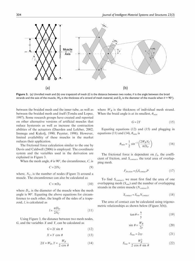
between the braided mesh and the inner tube, as well asbetween the braided mesh and itself (Tondu and Lopez,1997). Some research groups have created and reportedon other alternative versions of artificial muscles thatreduce hysteresis as well as increase the contractionabilities of the actuators (Daerden and Lefeber, 2002;Immega and Kukolj, 1990; Paynter, 1998). However,limited availability of these muscles in the marketreduces their application.
The frictional force calculation similar to the one byDavis and Caldwell (2006) is employed. The coordinatesystem and the variables used in the derivation areexplained in Figure 3.
When the mesh angle, u is 90�, the circumference, C, is
C = 2lNC ð9Þ
where, NC, is the number of nodes (Figure 3) around amuscle. The circumference can also be calculated as
C = pDO ð10Þ
where Do, is the diameter of the muscle when the meshangle is 90�. Equating the above equations for circum-ference to each other, the length of the sides of a trape-zoid, l, is calculated as
l =pDO
2NC
ð11Þ
Using Figure 3, the distance between two mesh nodes,G, and the variables X and Y, can be calculated as
G = 2l sin u ð12Þ
X = Y cos u ð13Þ
2X = WB, Y =WB
2 cos uð14Þ
where WB is the thickness of individual mesh strand.When the braid angle is at its smallest, umin
G = 2Y ð15Þ
Equating equations (12) and (15) and plugging inequations (11) and (14), umin is
umin =1
2sin�1 2WBNC
pDO
� �ð16Þ
The frictional force is dependent on fS, the coeffi-cient of friction, and Scontact, the total area of overlap-ping mesh.
Ffriction = fSScontactP ð17Þ
To find Scontact, we must first find the area of oneoverlapping mesh (Sone) and the number of overlappingstrands in the entire muscle (Ncontact).
Scontact = SoneNcontact ð18Þ
The area of contact can be calculated using trigono-metric relationships as shown below (Figure 3(b)).
tan u =x
yð19Þ
sin u =WB
2yð20Þ
Sone = 2xy ð21Þ
Sone =W 2
B
2 cos u sin uð22Þ
Figure 3. (a) Unrolled mesh and (b) one trapezoid of mesh (G is the distance between two nodes, u is the angle between the braidstrands and the axis of the muscle, WB is the thickness of a strand of mesh material, and Do is the diameter of the muscle when u = 90�).
304 Journal of Intelligent Material Systems and Structures 23(3)

At umin, the diameter is Dmin, and the length is Lmax.There are no gaps in the mesh, so the total surface areais Scontact
Surface area= pDminLmax = SoneNcontacts ð23Þ
Using the diameter and the length defined previously,plug umin in to find Dmin and Lmax. Solving for Ncontact
Ncontacts =2b2 sin2 umin cos
2 umin
nW 2B
ð24Þ
The total area of the overlapping strands, Scontact,
can be determined as
Scontacts =b2 sin2 umin cos
2 umin
n sin u cos uð25Þ
An increase in the overlapping area results inincreased strand friction, hence an increase in musclenonlinearity as well. The values of different variablesused in this article are listed in Table 1.
The model also clearly indicates that both PAMsand HAMs theoretically should provide the same force
output, as this is independent of operating fluid in sta-tic operation. In the following section, experimentalcharacterization of HAMs and their comparison withPAMs are discussed.
Characteristics of small-sized HAM
Experimental setup
In order to gain a better understanding of artificialmuscles, the muscles reported in this article were manu-factured in-house using off-the-shelf components andhave strokes ranging from 6.35 mm (¼ of an inch) to acouple millimeters. One of these in-house manufacturedartificial muscles and the components it consisted ofcan be seen in Figure 4. For the in-house artificial mus-cles, the maximum active length was measured fromthe inside of one tube clamp to the other when the mus-cle is fully stretched.
All muscles were constructed using the same materi-als, so the following muscle details applied to all themuscles used in the research:
Bladder: 1.5875 mm (1/16$) inner diameter, 0.7938mm (1/32$) thickness (therefore 3.1750 mm (1/8$)outer diameter).Braid: 3.1750 mm (1/8$) inner diameter at its thin-nest (so when muscle is stretched out).Diameter: Outer diameter is around 3.1750 mm (1/8$) at the smallest and should increase to about 6.35mm (1/4$) at the largest.
Experiments were conducted in order to staticallycharacterize the in-house mesoscale HAMs and PAMs.
Figure 4. Diagram of in-house artificial muscle components.1: soft latex inner rubber tube; 2: expandable polyester braided mesh sleeve; 3: single-barbed nylon tube fitting plug; 4: single-barbed nylon tube fitting
90� elbow port; 5: polyurethane tubing; 6: stainless steel pinch tube clamps; 7: tendon-like attachment.
Table 1. Table listing the some of the material properties.
Variables Value Units
Length of one side of a trapezoid of mesh, l 1 mmLength of one strand of mesh, b 25 mmNumber of turns one strand makes, n 1 —Thickness of a mesh strand, WB 0.25 mmNumber of nodes around a muscle, NC 18 —Diameter of muscle when u = 90�, Do 7.958 mmFriction coefficient, fs 0.1 —
Tiwari et al. 305

Tests were performed under isometric and isobaric condi-tions, using an Instron 1125 and Bose Electroforce,respectively. The isometric experiments were designed tomeasure the maximum force output of the muscles at vari-ous pressures, keeping the muscle length constant at itslongest position. Forces for the isometric tests wererecorded using a Load Star Sensors, iLoad Digital USBload cell. For the isometric experiments, each muscle wasinserted into the Instron 1125 and stretched to its fulllength. An initial preload is necessary due to the stretchingof the inner bladder in manufacturing. Once this wasdone, the load cell was calibrated. Each muscle was theninflated to pressures ranging from 0 to 100 psi in incre-ments of 20 psi at each stage. After reaching a pressure of100 psi, the system was reset, and the procedure wasrepeated two more times for a total of three trials witheach muscle.
Isobaric tests were performed to measure force out-put from the muscles on elongation/contraction at aseries of pressures that were held constant for eachexperiment. The muscles were tested at pressures rang-ing from 60 to 100 psi. For the isobaric tests, only mus-cles 22 mm in length were used.
Experiments were performed to measure free strokeand blocking force of the muscles. Free stroke is definedas the stroke with no load attachment, and blocking forceis the maximum force generated by the muscle with nodisplacement. For the free-stroke measurements, the mus-cles were mounted horizontally, fixed at one end of therig and attached to a linear position transducer (BournsInc., 101.6 mm-5 kO) at the other, as shown in Figure 5.Muscle is stretched to its maximum length at the startingof the experiment. The pressure was increased from 0 to100 psi by increments of 20 psi. The data was read fromthe linear potentiometer via a data acquisition unit(USB-1608FS, Measurement Computing). Each musclewas tested for a total of three times.
In the isometric and free-stroke experiments, threedifferent lengths of muscles were tested with two
different muscles for each length. Muscle active lengthsare listed in Table 2. The same sets of muscles were usedfor both hydraulic and pneumatic testing.
Results
The results of isobaric, isometric, and free-stroke experi-ments are shown in Figures 6 to 8. Although care wastaken to minimize any discrepancies, some variationscould be due to fabrication of the different muscles, as wellas the different tubing and fittings used between the pneu-matic and hydraulic setups. Isometric tests were performedusing three different muscle sizes and four muscles of eachsize. The results clearly show that the force increases withincreasing pressure as well as increasing length (Figure 5).Our test results show that the force output is indeed depen-dent on length, though to a lesser degree than its pressuredependence. The output from both PAM and HAM wassimilar as predicted by the model.
Another variable that plays an important role is thethreshold pressure, that is, the minimum pressurerequired to actuate a muscle. Each muscle needs to beactuated beyond its threshold pressure in order to per-form work. Due to the nonlinearity of the tubing, somevariation in threshold pressure in different muscles ofthe same size was observed. In addition, HAMs wereobserved to have some remnant strain on deflation.
Figure 8 compares PAMs and HAMs in terms offree stroke and blocking force. Muscles of size 80, 120,
Figure 5. Test rig for free-stroke measurement (solid lines denote fluid lines, while large dashed lines are electrical connections).DAQ represents data acquisition system.
Table 2. Table of muscle lengths.
Tests Muscle length (mm)
Isometric and free stroke 80120160
Isobaric 22
306 Journal of Intelligent Material Systems and Structures 23(3)

and 160 mm show an increase in both blocking forceand free stroke with an increase in pressure. The freestroke in the case of HAMs was observed to be margin-ally higher than PAMs. This could be due to betterpressure control in HAMs due to the use of anaccumulator.
It should also be noted that since the muscles usedin this research are small, parameters like end effectsdue to clamping in the muscles, friction, and noncylind-rical inflation of the tube has more pronounced effectson the muscle characteristics. The static model predictsidentical force output from the muscles irrespective ofthe operating fluid. HAM model modified with frictionbetween mesh strands and to a more realistic noncy-lindrical shape (resembling a cone) was observed toimprove the predictability of the model. Figure 9 com-pares model with experimental data for isobaric tests,which were performed to measure force output from
Figure 8. Blocking force and free stroke for (a) PAM and (b) HAM.
Figure 6. Isobaric tests performed using (a) PAM and (b) HAM of length 22 mm.
Figure 7. Isometric tests performed using 80-mm (subscript ‘‘s’’),120-mm (subscript ‘‘m’’), and 160-mm (subscript ‘‘l’’) PAMs and HAMs.
Tiwari et al. 307

the muscles on elongation and relaxation at a series ofpressures that were held constant for each experiment.Though the model predicts identical output from thePAM and HAM actuators, the experimental resultsshow marginally better performance from the hydraulicactuators.
Currently, the model does not take into account thenonlinear modulus term resulting from the viscoelasticnature of the tube. Though the viscoelastic behavior maynot be that prominent in static tests, it will most likelyhave large effect on the dynamic nature of the muscle.
Application of HAMS
The same valve that is often used for controllingdouble-acting cylinders, a 4/3 directional control valve,can actually be used for controlling an antagonistic pairof HAMs as well. These valves are typically used forsending pressurized fluid to both sides of the piston ofa double-acting cylinder (chamber A, piston side, andchamber B, rod side) to achieve motion in both direc-tions (Rabie, 2009). It can instead be used to controlthe fluid flow to both muscles of an antagonistic pair.
As stated previously, appropriately sized HAMsarranged in antagonistic pairs could conveniently beused to replace the existing double-acting cylinders.This would reduce the actuator weight by 84% andwould provide a mesoscale robot with more biologicalmotion. Figure 10 shows the two-degree-of-freedom(DOF) leg test rig with HAMs, which is discussed inthe following.
The system uses the same one pump and accumula-tor setup. The leg pieces were fabricated to accommo-date the HAMS, which were produced in-house. Twoservos actuate the spool valves to control the positionof the legs. Each spool valve controls one of the antago-nistic pairs of HAMS, either controlling the thigh or
the calf of the leg. The leg is controlled by an AtmelAtmega32 microcontroller using an open-loop control-ler. The controller sets the position of the valve to fullyinflate one of the two HAMS in the antagonistic pair,while venting the other HAM. After a given amount oftime, the controller toggles the position of the valves,moving the leg. The four positions that the HAM-actu-ated leg is toggled between can be seen in Figure 11. Itswitches between fully contracted and extended for eachleg segment in a walking gait motion.
At both the hip and knee joints, there is a conductiveplastic rotary potentiometer. The potentiometer at thehip joint measures the angle of the thigh with respect tohorizontal. The potentiometer at the knee joint sensesthe angle between the thigh and the calf. In Figure 11,the measured joint angle data for the walking gait tra-jectory that was prescribed are shown.
Discussion and conclusion
Both isobaric and isometric tests show similar perfor-mance from PAMs and HAMs. This is because the sta-tic force output is dependent on the construction of themuscle, position of the muscle, and the operating pres-sure. The static characteristics should be independentof operating fluid. The static force output from HAMis mostly a function of muscle dimensions, the operat-ing pressure, and what part of its stroke it is in. HAM’sstatic force increases proportionally as pressure is
Figure 10. HAM-actuated, two-DOF leg test stand.HAM: hydraulic artificial muscles; DOF: degree of freedom.
Figure 9. Comparing static model predictions withexperimental data in isobaric conditions using HAMs.
308 Journal of Intelligent Material Systems and Structures 23(3)

increased. This is true of traditional cylinder actuatorsas well. However, one main difference in the operationof the two is that the force a HAM creates is depen-dent on where it is in its stroke, while a hydraulic orpneumatic cylinder outputs approximately the sameforce regardless of its position. The static force anartificial muscle can produce increases with decreas-ing contraction ratio (Tondu and Lopez, 1997). Inother words, the maximum static force a muscle cancreate occurs at its fully stretched position, and thisdecreases all the way down to zero when the muscle isat its fully contracted state. The muscle acts essen-tially like a variable stiffness, nonlinear spring, whereits ‘‘resting’’ position is when the muscle is fully con-tracted. The model presented in this work could bemodified to incorporate the effect of variable stiffnessby using technique developed by Shan et al. (2009)and Philen (2011).
HAMs are most similar to single-acting cylinders, asboth types of actuators can only produce motion inone direction, generally only have one fluid port con-necting the system and actuator, and rely on an exter-nal force (or internal spring in the case of some single-acting cylinders) to return them to their original posi-tions (Rabie, 2009).Table 3 compares the in-house arti-ficial muscle (and when in an antagonistic pair) to adouble-acting cylinder purchased from Bimba.
As can be seen from the table, the in-house musclesare much cheaper than hydraulic cylinder and havehigher force-to-weight ratio. In addition, the musclesbuilt at the mesoscale have the advantage of simpleconstruction, compactness, and easy integration into arobotic system.
Despite of similar static behavior, we believe, usingmuscles in hydraulic environment will give user morecontrol over its stiffness and larger pressure and force
Figure 11. (a) The four positions that are toggled between and (b) the joint angle data from the open-loop control of the HAM-actuated leg.
Table 3. Comparison of in-house fluidic artificial muscle and double-acting Bimba cylinder
Fluidic artificial muscle (in-house) Double-acting cylinder (Bimba) (Bimba: Pneumatic cylinders, n.d)
Size 1/8$ diameter and 4$ long 5/16$ bore and 4$ longStroke 25.4 mm 25.4 mmDry weight 0.0179 N (0.0359 N for pair) 0.2179 NMaximum force at 100 psi 35.5858 N 34.1179 NMaximum force-to-weightratio
1990 (995 for pair) 157
Cost US$ 0.96 (US$1.92 for pair) US$21.09
Tiwari et al. 309

bandwidth (Focchi et al., 2010). Using water as theworking fluid as opposed to air has also been shown tohave better load variations and hence improved control(Focchi et al., 2010). Also the energy cost of compressinga fluid is lower than compressing air. Using water or oilcan also be beneficial for underwater robotic applicationswhere the surrounding fluid can be used as the reservoir.
The model developed was able to predict muscle per-formance in static conditions. This model can be modi-fied to include nonlinear dynamic behavior of themuscle. This can be achieved by incorporating variablestiffness term in the model.
Future work
In the future, the static model will incorporate moreartificial muscle properties such as a factor to accountfor the stiffness of the mesh, and the viscoelastic prop-erties of the inner latex/rubber tubing to attain a moreaccurate representation of the muscles. Furthermore, aseries of dynamic tests will be performed on HAMsand PAMs. These tests will provide the most insightinto the main differences in operation of the two actua-tors. Once these experiments have been performed, adynamic model of hydraulic and pneumatic operationwill be developed.
Some drawbacks of PAMs include the compressibil-ity of the working fluid, air, and the amount of damp-ing. These characteristics result in poorer dynamicresponse, as well as undesired oscillations of the actua-tors, respectively (Ahn and Chau, 2007; Klute et al.,2002). We hypothesize that utilizing oil as the workingfluid, instead of air, will reduce the aforementionedissues of PAMs and yield better dynamic performancein general. Since oil is more viscous than air, using oilas the operating fluid could inherently help damp outthe undesired oscillations that occur in PAMs.Response time could also potentially be improved sig-nificantly as traditional hydraulic systems tend to haveresponse times about 50 times faster than equivalentpneumatic systems (Blackburn, 1960). The overall sys-tem efficiency has the potential to be increased greatly,as traditional pneumatic systems are rarely over 30%efficient due to the constant compressing of the work-ing fluid, while their hydraulic counterparts are seldomover 60% efficient (Blackburn, 1960).
Acknowledgements
The authors would like to thank to Karl Gluck and JamesPaulos for their invaluable suggestions and help. Authorswould also like to thank Alan Argondizza for getting the proj-ect initiated. Also authors would like to acknowledge that thefirst two authors have equal contribution in the paper.
Funding
The financial support on this project was provided by Moog Inc.
References
Ahn K and Chau NH (2007) Intelligent phase plane switching
control of a pneumatic muscle robot arm with magneto-
rheological brake. Journal of Mechanical Science and Tech-
nology 21(8): 1196–1206.Beullens TH (1989) Hydraulic or pneumatic drive device. US
patent 4,841,845.Bimba: Pneumatic Cylinders (n.d.) Available at: http://
www.bimba.com/Products/OriginalLineCylinders/Blackburn JF (1960) Fluid Power Control. Cambridge: MIT
Press.Caldwell DG, Razak A and Goodwin M (1993) Braided arti-
ficial muscle actuators. In: Proceedings of 3rd IFAC sympo-
sium on intelligent autonomous vehicles, Southampton, UK,
pp.507–512.Chang X and Lilly JH (2003) Fuzzy control for pneumatic
muscle tracking via evolutionary tuning. Journal of Intelli-
gent Automation and Soft Computing 9(4): 227–244.Chen Y, Yin W, Liu Y, et al. (2011) Structural design and
analysis of morphing skin embedded with pneumatic mus-
cle fibers. Smart Materials and Structures 20: 085033.Chou CP and Hannaford B (1996) Measurements and model-
ing of McKibben pneumatic artificial muscles. IEEE
Transactions on Robotics and Automation 12(1): 90–102.Daerden F (1999) Conception and realization of pleated pneu-
matic artificial muscles and their use as compliant actuation
elements. PhD Thesis, Vrije Universiteit Brussel, Belgium.Daerden F and Lefeber D (2001) The concept and design of
pleated pneumatic artificial muscles. International Journal
of Fluid Power 2(3): 41–50.Daerden F and Lefeber D (2002) Pneumatic artificial muscles:
actuators for robotics and automation. European Journal
of Mechanical and Environmental Engineering 47(1): 10–21.Davis S, Tsagaraksi N, Canderle J and Caldwell DG (2003)
Enhanced modeling and performance in braided pneu-
matic muscle actuators. International Journal of Robotics
Research 22(3-4): 213–227.Davis S and Caldwell DG (2006) Braid effects on contractile
range and friction modeling in pneumatic muscle actuators.
International Journal of Robotics Research 25(4): 359–369.Ferris DP, Czerniecki JM and Hannaford B (2005) An ankle-
foot orthosis powered by artificial pneumatic muscles.
Journal of Applied Biomechanics 21(2): 189–197.Fluidic Muscle DMSP/MAS (n.d.) From FESTO. Available
at: http://www.festo.com/cms/en-us_us/2498.htmFocchi M, Guglielmino E, Semini C, et al. (2010) Water/air per-
formance analysis of fluidic muscle. IEEE/RSJ International
Conference on Intelligent Robots and Systems 2194–2199.Ho HW, Luk BL, Bradbeer RS, Yeung LF, Zhang HJ and
Mould M (2000) The design of a hydraulically powered
leg for an underwater six-legged robot. Mechatronics and
Machine Vision J. Billingsley (Ed. Baldock) Hertfordshire
U.K.: Research Studies 263–274.Immega G and Kukolj M (1990) Axially contractible actuator.
US patent 4,939,982.Immega GB (1986) ROMAC muscle powered robots. Techni-
cal report MS86–777, Society of Manufacturing Engineers
Dearborn.Immega GB (1987) ROMAC actuators for micro robots. In:
IEEE micro robotics and teleoperators workshop 9th
November, Hyannis, MA.
310 Journal of Intelligent Material Systems and Structures 23(3)

Klute GK and Hannaford B (2000) Accounting for elasticenergy storage in Mckibben artificial muscle actuators.
Journal of Dynamic Systems, Measurements and Control,122(2): 386–388.
Klute GK, Czerniecki JM and Hannaford B (2002) Artificial
muscles: actuators for biorobotic systems. The Interna-
tional Journal of Robotics Research 21(4): 295–309.Kothera CS, Woods BKS, Sirohi J, Wereley NM and Chen
PC (2010) Fluid-driven artificial muscles as mechanismsfor controlled actuation, United States Patent No.7,837,144.
Ku, KKK and Bradbeer, RS (2006) Static Model of the
Shadow Muscle under Pneumatic Testing. Proceedings of
the 4th Regional Inter-University Postgraduate Electrical
and Electronics Engineering Conference Macau, PRC, 13-14 July.
Ku KKK, Bradbeer RS, Lam KKY, Yeung LF and Li RCW
(2009) A novel actuator for underwater robots IEEE Journal
of Oceanic Engineering 34(3): 331–342.Lee YK and Shimoyama I (1999) A skeletal framework artifi-
cial hand actuated by pneumatic artificial muscles. Pro-ceedings of the IEEE International Conference on Robotics
and Automation 2: 926–931.Lilly JH (2003) Adaptive tracking for pneumatic muscle
actuators in bicep and tricep configurations. IEEE Trans-
actions on Neural systems and rehabilitation engineering 11:
333–339.Nakamura T, Saga N and Yaegashi K (2003) Development
of a pneumatic artificial muscle based on biomechanical
characteristics. IEEE International Conference on Industrial
Technology 2: 729–734.Noritsugu T and Tanaka T (1997) Application of rubber
artificial muscle manipulator as a rehabilitation robot.
IEEE/ASME Transactions on Mechatronics 2(4): 259–267.Paynter HM (1998)High-pressure fluid-driven tension actuators
and methods for constructing them. US patent 4,751,869.Philen M (2011) Force tracking control of fluidic flexible
matrix composite variable stiffness structures. Journal ofIntelligent Material Systems and Structures 22(1): 31–43.
Rabie MG (2009) Fluid Power Engineering. New York:
McGraw-Hill Companies, Inc.Reynolds DB, Repperger DW, Phillips CA, Bandry G (2003)
Modeling the dynamic characteristics of pneumatic mus-
cle. Annals of Biomedical Engineering, 31: 310–317.Robinson RM, Kothera CS, Woods BKS, et al. (2011) High
specific power actuators for robotic manipulators. Journalof Intelligent Material Systems and Structures 22(13):
1501–1511.Ryu D, Moon KW, Nam H, et al. (2008) Micro hydraulic sys-
tem using slim artificial muscles for a wearable haptic glove.
In: Proceedings of the IEEE international conference on intel-
ligent robots and systems, Nice, France, pp.3028–3033.Schulte HF (1961) The characteristics of the Mckibben artifi-
cial muscle. The Application of External Power in Pros-thetics and Orthotics, National Academy of Sciences–National Research Council, Lake 874: 94–115.
Shadow Robot Company (n.d.) 30 mm Air Muscle – Specifi-
cation. Available at: http://www.shadowrobot.com/Shan Y, Philen M, Lotfi A, et al. (2009) Variable stiffness
structures utilizing fluidic flexible matrix composites. Jour-
nal of Intelligent Material Systems and Structures 20(4):443–456.
Solano B and Rotinat-Libersa C (2011) Compact and light-weight hydraulic actuation system for high performance
millimeter scale robotic applications: modeling and experi-ments. Journal of Intelligent Material systems and Struc-
tures 22: 1479–1487.Tondu B, Ippolito S and Guiochet J (2005) A seven degree of
freedom robot arm driven by pneumatic artificial muscles
for humanoid robot. The International Journal of RoboticsResearch 24(4): 257–274.
Tondu B and Lopez P (1997) The McKibben muscle and its
use in actuating robot-arms showing similarities with
human arm behaviour. Industrial Robot 24(6): 432–439.Tondu B and Lopez P (2000) Modeling and Control of
McKibben Artificial Muscle Robot Actuators. IEEE Con-
trol Systems Magazine, 20(2): 15–38.Tri VM, Tjahjowidodo T, Ramon H and Van Brussel H
(2009) Non-local Memory Hysteresis in A Pneumatic Arti-
ficial Muscle Proceedings of the 17th Mediterranean Con-ference on Control and Automation, Thessaloniki, Greece,640–645.
Tri VM, Tjahjowidodo T, Ramon H and Van Brussel H
(2010) A new approach to modeling hysteresis in a pneu-matic artificial muscle using the Maxwell-slip model.
IEEE/ASME Transaction on Mechatronics, 16(1): 177–186.
Vanderborght B, Verrelst B, Ham RV, et al. (2006) Control-ling a bipedal walking robot actuated by pleated pneu-
matic artificial muscles. Journal Robotica 24(4): 401–410.Varga Z and Mou�cka M (2009) Mechanics of pneumatic arti-
ficial muscle. Journal of Applied Science in the Thermody-
namics and Fluid Mechanics 3(2) (http://astfm.tul.cz/journal/year-2009/2st-issue/)
Waycaster G, Wu S-K and Shen X (2011) Design and control
of a pneumatic artificial muscle actuated above-knee pros-thesis. Journal of Medical Devices 5(1): 031003.
Wereley N, Kothera C, Bubert E, et al. (2009) Pneumatic arti-ficial muscles for aerospace applications. In: 17th struc-
tures, structural dynamics, and materials conference PalmSpring, California.
Wickramatunge KC and Leephakpreeda T (2010) Study on
mechanical behavior of pneumatic artificial muscle. Inter-national Journal of Engineering Science 48: 188–198.
Wigging MB, Sawicki GS and Collins SH (2011) An exoskele-
ton using controlled energy storage and release to aid anklepropulsion. IEEE International Conference on Rehabilita-
tion Robotics 1–5.Winters JM (1995) Braided artificial muscles: mechanical prop-
erties and future uses in prosthetics/orthotics. In: Proceed-ings of the RESNA 13th annual conference Washington DC,
173–174.Wisse M and Frankenhuyzen JV (2003) Design and construc-
tion of Mike; 2D autonomous biped based on passive
dynamic walking. In: Proceedings of international sympo-
sium on adaptive motion of animals and machines Kyoto,Japan, p.3.
Woods BKS, Kothera CS and Wereley NM (2011) Wind tun-
nel testing of a helicopter rotor trailing edge flap actuatedvia pneumatic artificial muscles. Journal of Intelligent
Material Systems and Structures 22(13): 1513–1528.Yarlott JM (1972) Fluid actuator. US patent 3,645,173.Yerkes N and Wereley N (2008) Pneumatic artificial muscle
activation for trailing edge flaps. In: 46th AIAA aerospace
Tiwari et al. 311

sciences meeting and exhibit, AIAA paper 2008-1418 7-10January, Reno, Nevada.
Yoshinada H, Yamazaki T, Suwa T, et al. (1991) Seawaterhydraulic actuator system for underwater manipulator. In:Proceedings of 5th international conference advanced robot,Pisa, Italy, vol. 2, pp.1330–1335.
Appendix 1
Notation
Symbol Definition Value UnitsF Force output — Nl Length of one side of a
trapezoid of mesh1 mm
P Pressure of fluid insidemuscle
— psi
V Volume of muscle — mm3
L Length of muscle — mmu Mesh angle — deg
D Diameter of muscle — mmC Circumference of muscle — mmB Length of one strand of
mesh25 mm
N Number of turns onestrand makes
1 —
G Distance between two meshnodes
— mm
WB Thickness of a mesh strand 0.25 mmNC Number of nodes around a
muscle18 —
Do Diameter of muscle when u
= 90o7.958 mm
Ffriction Force from friction — NScontact Total area of overlapping
strands— mm2
fs Friction coefficient 0.1 —E Contraction ratio — —
312 Journal of Intelligent Material Systems and Structures 23(3)