Characterization of the Physical and Hydraulic Properties ...

SRNL-STI-2008-00421, REVISION 0
Key Words:
Saltstone, Concrete, Hydraulic Conductivity, Moisture Retention Characteristics
Retention: Permanent HYDRAULIC AND PHYSICAL PROPERTIES OF SALTSTONE GROUTS
AND VAULT CONCRETES
Kenneth Dixon John Harbour Mark Phifer
NOVEMBER 2008
Savannah River National Laboratory Savannah River Nuclear Solutions Aiken, SC 29808
Prepared for the U.S. Department of Energy Under Contract Number DE-AC09-08SR22470

SRNL-STI-2008-00421, REVISION 0
DISCLAIMER
This work was prepared under an agreement with and funded by the U.S. Government. Neither the U. S. Government or its employees, nor any of its contractors, subcontractors or their employees, makes any express or implied: 1. warranty or assumes any legal liability for the accuracy, completeness, or for the use or results of such use of any information, product, or process disclosed; or 2. representation that such use or results of such use would not infringe privately owned rights; or 3. endorsement or recommendation of any specifically identified commercial product, process, or service. Any views and opinions of authors expressed in this work do not necessarily state or reflect those of the United States Government, or its contractors, or subcontractors.
Printed in the United States of America
Prepared For
U.S. Department of Energy

SRNL-STI-2008-00421, REVISION 0
Key Words:
Saltstone, Concrete, Hydraulic Conductivity, Moisture Retention Characteristics
Retention: Permanent HYDRAULIC AND PHYSICAL PROPERTIES OF SALTSTONE GROUTS
AND VAULT CONCRETES
NOVEMBER 2008
Savannah River National Laboratory Savannah River Nuclear Solutions Aiken, SC 29808
Prepared for the U.S. Department of Energy Under Contract Number DE-AC09-08SR22470


SRNL-STI-2008-00421, REVISION 0
- iv -
TABLE OF CONTENTS LIST OF FIGURES ...................................................................................................................... v LIST OF TABLES ........................................................................................................................ v LIST OF ACRONYMS .............................................................................................................. vii 1.0 EXECUTIVE SUMMARY .................................................................................................... 1 2.0 INTRODUCTION................................................................................................................... 2 3.0 METHODS .............................................................................................................................. 3
3.1 Saltstone Sample Preparation ............................................................................................ 4 3.1.1 DDA Saltstone Sample Preparation ............................................................................ 4 3.1.2 ARP/MCU Saltstone Sample Preparation .................................................................. 4 3.1.3 SWPF Saltstone Sample Preparation.......................................................................... 4 3.1.4 Saltstone Permeant Preparation .................................................................................. 5
3.2 concrete Sample Preparation ............................................................................................. 5 3.2.1 Vault 1/4 Concrete Preparation ................................................................................... 5 3.2.2 Vault 2 Concrete Preparation ...................................................................................... 6
3.3 Hydraulic and Geotechnical Testing.................................................................................. 7 3.3.1 Saltstone Grout Hydraulic and Physical Property Testing....................................... 7 3.3.2 Vault Concrete Hydraulic and Physical Property Testing........................................ 9
3.4 Determination of van Genuchten Transport Parameters.............................................. 10 4.0 RESULTS .............................................................................................................................. 12
4.1 Fresh Properties of the Saltstone mixes........................................................................... 12 4.2 Heat of Hydration of the Saltstone mixes........................................................................ 12 4.3 Compressive Strength Testing.......................................................................................... 12 4.4 Saltstone and Vault Concrete Hydraulic and Physical Properties ............................... 13
4.4.1 DDA Saltstone Hydraulic and Physical Properties.................................................. 13 4.4.2 ARP/MCU Saltstone Hydraulic and Physical Properties........................................ 14 4.4.3 SWPF Saltstone Hydraulic and Physical Properties ............................................... 15 4.4.4 Vault 1/4 Concrete Hydraulic and Physical Properties........................................... 16 4.4.5 Vault 2 Mix 1 Concrete Hydraulic and Physical Properties ................................... 17 4.4.6 Vault 2 Mix 2 Concrete Hydraulic and Physical Properties ................................... 17
4.5 Analysis of Moisture Retention Characteristics ............................................................. 18 4.6 Recommended Hydraulic and Physical Properties ........................................................ 19
5.0 SUMMARY ........................................................................................................................... 20 6.0 REFERENCES...................................................................................................................... 22 APPENDIX A. Development of Saltstone Permeants ............................................................ 55 APPENDIX B. Strength Reports.............................................................................................. 59 APPENDIX C. MCT Data Sheets on Saltstone....................................................................... 72 APPENDIX D. MCT Data Sheets on Vault Concretes......................................................... 139 APPENDIX E. Calculations to correct for salt precipitation .............................................. 173 APPENDIX F. Recommended Characteristic Curve Data.................................................. 180 APPENDIX G. Design Check Documentation ...................................................................... 202

SRNL-STI-2008-00421, REVISION 0
- v -
LIST OF FIGURES
Figure 1. Bivariate fit of simulant density as a function of measured weight percent solids. ..... 24 Figure 2. Normalized Heat (J/g of premix) from DDA, ARP/MCU, and SWPF saltstone at 0.60
w/pm ratio. ............................................................................................................................. 24 Figure 3. Compressive strength as a function of curing period for DDA, ARP/MCU, and SWPF
Saltstone. ................................................................................................................................ 25 Figure 4. Compressive strength as a function of curing period for Vault 1/4, Vault 2 Mix 1, and
Vault 2 Mix 2. ........................................................................................................................ 25 Figure 5. Moisture retention curves for the 28 day DDA saltstone samples. .............................. 26 Figure 6. Moisture retention curves for the 90 day DDA saltstone samples. .............................. 26 Figure 7. Moisture retention curves for the 28 day ARP/MCU saltstone samples...................... 27 Figure 8. Moisture retention curves for the 90 day ARP/MCU saltstone samples...................... 27 Figure 9. Moisture retention curves for the 28 day SWPF saltstone samples. ............................ 28 Figure 10. Moisture retention curves for the 90 day SWPF saltstone samples. .......................... 28 Figure 11. Moisture retention curves for the 28 day Vault 1/4 concrete samples. ...................... 29 Figure 12. Moisture retention curves for the 28 day Vault 2 Mix 1 concrete samples................ 29 Figure 13. Moisture retention curves for the 28 day Vault 2 Mix 2 concrete samples................ 30 Figure 14. Characteristic Curves for the DDA Saltstone (using 28 and 90 day retention data).. 30 Figure 15. Characteristic Curves for the ARP/MCU Saltstone (using 28 and 90 day retention
data)........................................................................................................................................ 31 Figure 16. Characteristic Curves for the SWPF Saltstone (using 28 and 90 day retention data).31 Figure 17. Characteristic curves for MCU saltstone samples as determined by INL reported by
Dixon and Phifer (2007)......................................................................................................... 32 Figure 18. Characteristic Curves for the Vault 1/4 Concrete (based on 28 day minimum curing
period). ................................................................................................................................... 32 Figure 19. Characteristic Curves for the Vault 2 Mix 1 Concrete (based on 28 day minimum
curing period). ........................................................................................................................ 33 Figure 20. Characteristic Curves for the Vault 2 Mix 2 Concrete (based on 28 day minimum
curing period). ........................................................................................................................ 33
LIST OF TABLES Table 1. Saltstone Cementitious Materials (premix). .................................................................. 34 Table 2. Recipe for DDA Simulant used to Prepare Simulated Saltstone Grout Samples and the
Permeant used for Hydraulic and Physical Testing. .............................................................. 34 Table 3. Recipe for ARP/MCU Simulant used to Prepare Simulated Saltstone Grout Samples
and the Permeant used for Hydraulic and Physical Testing................................................... 34 Table 4. Recipe for SWPF Simulant used to Prepare Simulated Saltstone Grout Samples and the
Permeant used for Hydraulic and Physical Testing. .............................................................. 35 Table 5. Simulant and Permeant Properties................................................................................. 35 Table 6. Saltstone Vault 1/4 Concrete Formulations. ................................................................... 36 Table 7. Ingredients Used to Prepare the Vault 1/4 Concrete Samples. ...................................... 37 Table 8. Saltstone Vault 2, Mix 1 Concrete Formulation (670 lbs/cu yd Cementitious Material,
Class 3 Sulfate Resistant Concrete). ...................................................................................... 38

SRNL-STI-2008-00421, REVISION 0
- vi -
Table 9. Saltstone Vault 2, Mix 2 Concrete Formulation (710 lbs/cu yd Cementitious Material, Class 3 Sulfate Resistant Concrete). ...................................................................................... 39
Table 10. Ingredients Used to Prepare the Vault 2 Mix 1 and Mix 2 Concrete Samples. ........... 40 Table 11. Fresh Properties of the DDA, ARP/MCU, and SWPF Saltstone................................. 41 Table 12. Compressive Strength for the DDA Saltstone Grout (Cast 3/18/2008)....................... 41 Table 13. Compressive Strength for the ARP/MCU Saltstone Grout (Cast 3/31/2008). ............ 41 Table 14. Compressive Strength for the SWPF Saltstone Grout (Cast 4/22/2008). .................... 41 Table 15. Compressive Strength for the Vault 1/4 Concrete (Cast 5/05/2008). .......................... 42 Table 16. Compressive Strength for the Vault 2 Mix 1 Concrete (Cast 3/25/2008). .................. 42 Table 17. Compressive Strength for the Vault 2 Mix 2 Concrete (Cast 6/24/2008). .................. 42 Table 18. Hydraulic Properties of DDA Saltstone as Measured by MCT................................... 43 Table 19. Physical Properties of DDA Saltstone as Measured by MCT. .................................... 43 Table 20. Hydraulic Properties of ARP/MCU Saltstone as Measured by MCT. ........................ 44 Table 21. Physical Properties of ARP/MCU Saltstone as Measured by MCT............................ 44 Table 22. Hydraulic Properties of SWPF Saltstone as Measured by MCT. ................................ 45 Table 23. Physical Properties of SWPF Saltstone as Measured by MCT. .................................. 45 Table 24. Hydraulic Properties of Vault 1/4 Concrete as Measured by MCT............................. 46 Table 25. Physical Properties of Vault 1/4 Concrete as Measured by MCT. .............................. 46 Table 26. Hydraulic Properties of Vault 2 Mix 1 Concrete as Measured by MCT. .................... 47 Table 27. Physical Properties of Vault 2 Mix 1 Concrete as Measured by MCT........................ 47 Table 28. Hydraulic Properties of Vault 2 Mix 2 Concrete as Measured by MCT. .................... 48 Table 29. Physical Properties of Vault 2 Mix 2 Concrete as Measured by MCT........................ 48 Table 30. Summary Hydraulic Properties for Saltstone and Vault Concrete Samples................ 49 Table 31. Summary Physical Properties for Saltstone and Vault Concrete Samples. ................. 50 Table 32. Moisture Retention Data for DDA Saltstone as measured by MCT............................ 51 Table 33. Moisture Retention Data for the ARP/MCU Saltstone as measured by MCT. ........... 51 Table 34. Moisture Retention Data for the SWPF Saltstone as measured by MCT.................... 52 Table 35. Moisture Retention Data for Vault 1/4 Concrete as measured by MCT. .................... 52 Table 36. Moisture Retention Data for Vault 2 Mix 1 Concrete as measured by MCT.............. 53 Table 37. Moisture Retention Data for Vault 2 Mix 2 Concrete as measured by MCT.............. 53 Table 38. Van Genuchten Transport Parameters. ......................................................................... 54 Table 39. Recommended Saltstone and Vault Concrete Hydraulic and Physical Parameter Values
................................................................................................................................................ 54

SRNL-STI-2008-00421, REVISION 0
- vii -
LIST OF ACRONYMS
AEA Air entraining admixture ARP Actinide Removal Process CSSX Caustic side solvent extraction DDA Deliquification, Dissolution, and Adjustment INL Idaho National Laboratory ITP In-Tank Precipitation Facility LLW Low Level Waste MCT Mactec Engineering and Consulting, Inc. MCU Modular Caustic Side Solvent Extraction Unit PA Performance Assessment RETC RETention Curve SDF Saltstone Disposal Facility SRNL Savannah River National Laboratory SRS Savannah River Site SWPF Salt Waste Processing Facility USDA United States Department of Agriculture USDOE United States Department of Energy w/pm water to premix ratio WRA Water reducing admixture WSRC Washington Savannah River Company

SRNL-STI-2008-00421, REVISION 0
Page 1 of 204
1.0 EXECUTIVE SUMMARY
The Saltstone Disposal Facility (SDF), located in the Z-Area of the Savannah River Site (SRS), is used for the disposal of low-level radioactive salt solution. The SDF currently contains two vaults: Vault 1 (6 cells) and Vault 4 (12 cells). Additional disposal cells are currently in the design phase. The individual cells of the saltstone facility are filled with saltstone. Saltstone is produced by mixing the low-level radioactive salt solution, with blast furnace slag, fly ash, and cement (dry premix) to form a dense, micro-porous, monolithic, low-level radioactive waste form. The saltstone is pumped into the disposal cells where it subsequently solidifies. Significant effort has been undertaken to accurately model the movement of water and contaminants through the facility. Key to this effort is an accurate understanding of the hydraulic and physical properties of the solidified saltstone. To date, limited testing has been conducted to characterize the saltstone. The primary focus of this task was to estimate the hydraulic and physical properties of three types of saltstone and two vault concretes. The saltstone formulations included saltstone premix batched with 1) Deliquification, Dissolution, and Adjustment (DDA) salt simulant (w/pm 0.60), 2) Actinide Removal Process (ARP)/Modular Caustic Side Solvent Extraction Unit (MCU) salt simulant (w/pm 0.60), and 3) Salt Waste Processing Facility (SWPF) salt simulant (w/pm 0.60). The vault concrete formulations tested included the Vault 1/4 concrete and two variations of the Vault 2 concrete (Mix 1 and Mix 2). Wet properties measured for the saltstone formulations included yield stress, plastic viscosity, wet unit weight, bleed water volume, gel time, set time, and heat of hydration. Hydraulic and physical properties measured on the cured saltstone and concrete samples included saturated hydraulic conductivity, moisture retention, compressive strength, porosity, particle density, and dry bulk density. These properties were determined following a minimum 28 day curing period. Additional testing of the three saltstone formulations was conducted following a minimum 90 day curing period. The compressive strength of each saltstone and concrete material was measured at approximately 14, 28, 56, and 90 days. Recommended hydraulic property values for each saltstone grout and the vault concretes are provided. The hydraulic properties provided for each material include the saturated hydraulic conductivity, dry bulk density, particle density, and porosity. In addition, water retention data are presented for each material along with the van Genuchten transport parameters as determined using the RETC code.

SRNL-STI-2008-00421, REVISION 0
Page 2 of 204
2.0 INTRODUCTION The Saltstone Disposal Facility (SDF), located in the Z-Area of the Savannah River Site (SRS), is used for the disposal of low-level radioactive salt solution. The SDF currently contains two vaults: Vault 1 and Vault 4. Additional disposal cells are currently in the design phase. Vault 4 is approximately 200 feet wide, 600 feet in length, and 26 feet in height. Vault 4 is divided into 12 cells with each cell measuring about 100 feet by 100 feet (Phifer et al., 2006). Vault 1 is half the size of Vault 4 measuring approximately 100 feet wide by 600 feet long with 6 cells. The individual cells of the saltstone facility are filled with saltstone. Saltstone is produced by mixing low-level radioactive salt solution, with blast furnace slag, fly ash, and cement to form a dense, micro-porous, monolithic, low-level radioactive waste form. The saltstone material contains no coarse or fine aggregate and is pumped into the disposal cells where it subsequently solidifies. SRS is currently in the process of revising the Performance Assessment (PA) for the SDF as required by DOE Order 435.1, Radioactive Waste Management. As part of this revision, a significant effort will be undertaken to accurately model the movement of water and contaminants through the SDF. Key to this effort is an accurate understanding of the hydraulic and physical properties of the specific saltstone formulations to be placed in the SDF. Initial testing of the saltstone grout was conducted by Yu et al. (1993). This characterization work indicated that intact saltstone had a saturated intrinsic permeability of 5.3 x 10⁻⁹ darcies using a brine solution; and a saturated hydraulic conductivity relative to water of 5.19 x 10⁻¹² cm/s (Yu et al., 1993). These results have not been corroborated by subsequent testing and are now thought to be biased due to potential precipitation of the brine solution within the saltstone samples. Langton (1986) measured the saturated hydraulic conductivity of “Reference Saltstone” samples containing 42.5% salt solution and 57.5% (by mass) blended cement. Langton (1986) reported saturated hydraulic conductivity of this material to be 1.1 x 10⁻⁸ cm/sec for a sample cured for 60 days. Additionally, Langton (1986) reported the results of previous hydraulic testing on saltstone samples (made with varying amounts of salt solution) with results ranging from 3.0 x 10⁻⁹ cm/sec to <1.0 x 10⁻¹¹ cm/sec. More recently, Harbour et al. (2007a) estimated the saturated hydraulic conductivity of a MCU saltstone using a beam bending technique. Harbour et al. (2007a) estimated the hydraulic conductivity of the saltstone ranged from 1.4 to 3.4 x 10⁻⁹ cm/sec, which is about three orders of magnitude more permeable than reported by Yu et al. (1993). Furthermore, Harbour et al. (2007a) reported a porosity of 0.62 which is substantially greater than that reported by Yu et al. (1993). Dixon and Phifer (2007) estimated the saturated hydraulic conductivity of a MCU saltstone using standard geotechnical testing methods (ASTM 5084, flexible wall permeameter). Dixon and Phifer (2007) estimated the saturated hydraulic conductivity of the MCU saltstone relative to two different permeating fluids: groundwater equilibrated with vault concrete simulant and saltstone
SRNL-STI-2008-00421, REVISION 0
Page 3 of 204
pore fluid simulant. The saturated hydraulic conductivity of the saltstone relative to the groundwater equilibrated with vault concrete simulant was estimated to be 1.5 x 10⁻⁸ cm/sec. The saturated hydraulic conductivity of the saltstone relative to the saltstone pore fluid simulant was estimated to be 5.3 x 10⁻⁹ cm/sec. The dry bulk density of the saltstone was estimated to range from 0.95 to 1.06 g/cm3 with an average of 0.99 g/cm3. The porosity was estimated to range from 0.578 to 0.613 with an average of 0.596. The purpose of this task was to measure the hydraulic and physical properties of three saltstone grout formulations and two vault concrete formulations. The saltstone formulations include saltstone premix batched with 1) Deliquification, Dissolution, and Adjustment (DDA) salt simulant (w/pm 0.60), 2) Actinide Removal Process (ARP)/ Modular Caustic Side Solvent Extraction Unit (MCU) salt simulant (w/pm 0.60), and 3) Salt Waste Processing Facility (SWPF) salt simulant (w/pm 0.60). The vault concretes tested include the Vault 1/4 concrete and the Vault 2 concretes (Mix 1 and Mix 2). Wet properties measured for the saltstone grout formulations include yield stress, plastic viscosity, wet unit weight, bleed water volume, gel time, set time, and heat of hydration. Hydraulic and physical properties measured on the cured samples included saturated hydraulic conductivity, moisture retention, porosity, and dry bulk density. These properties were determined following a minimum 28 day curing period. Additional testing was conducted on the saltstone samples following a minimum 90 day curing period. The sections that follow discuss the methods used to test samples of the saltstone and vault concretes and the results of the testing.
3.0 METHODS The purpose of this task was to measure the hydraulic and physical properties of three saltstone grout formulations and two vault concrete formulations. The saltstone formulations tested were the DDA, ARP/MCU, and the SWPF formulations. The vault concrete formulations tested were the Vault 1/4 concrete and two variations of the Vault 2 concrete. All samples were tested for saturated hydraulic conductivity, moisture retention characteristics, compressive strength, dry bulk density, particle density, and porosity. The following samples of each material were tested to determine the hydraulic and physical properties using standard ASTM methods (or equivalent):
• 3 samples of DDA saltstone following a minimum 28 day curing period (w/pm 0.60) • 3 samples of DDA saltstone following a minimum 90 day curing period (w/pm 0.60) • 3 samples of ARP/MCU saltstone following a minimum 28 day curing period (w/pm 0.60) • 3 samples of ARP/MCU saltstone following a minimum 90 day curing period (w/pm 0.60) • 3 samples of SWPF saltstone following a minimum 28 day curing period (w/pm 0.60) • 3 samples of SWPF saltstone following a minimum 90 day curing period (w/pm 0.60) • 3 samples of Vault 1/4 concrete following a minimum 28 day curing period • 3 samples of Vault 2, Mix 1 concrete following a minimum 28 day curing period • 3 samples of Vault 2, Mix 2 concrete following a minimum 28 day curing period

SRNL-STI-2008-00421, REVISION 0
Page 4 of 204
3.1 SALTSTONE SAMPLE PREPARATION Samples of three saltstone formulations were prepared for compressive strength and hydraulic and physical property testing. The cementitious materials used in the premix for each of the saltstone grout formulations were identical and were comprised of Class F fly ash (45 wt%), Grade 100 blast furnace slag (45 wt%), and Type II Portland cement (10 wt%) with an as-batched water to premix ratio (w/pm) of 0.60 (Table 1). The cementitious materials were received in 5 gallon containers from the vendors during truck delivery of the bulk materials to SPF. The cementitious materials are therefore part of one of the batches actually used in production of saltstone. For each saltstone grout formulation, the cementitious materials were mixed with a salt simulant representative of three types of decontaminated salt solution to be processed by the saltstone facility. The recipes for the simulants are presented in Table 2 through Table 4 and the physical properties of the simulants are presented in Table 5. Wet properties measured for the saltstone formulations included yield stress, plastic viscosity, wet unit weight, bleed water volume, gel time, set time, and heat of hydration. The methods of Harbour et al. (2005) were followed to determine yield stress, plastic viscosity, gel time, bleed water volume, and wet unit weight. Porosity and heat of hydration were determined following the method of Harbour et al. 2007b and 2007c, respectively.
3.1.1 DDA Saltstone Sample Preparation Three large batches of DDA Saltstone were batched (~ 5 kg each) to provide a sufficient amount of grout for all of the testing. Seven test cylinders (2.8 x 6 inch) were filled for hydraulic testing. The mold samples were capped, sealed, and allowed to cure in the laboratory at ambient temperature for a minimum of 28 or 90 days prior to testing. Bleed liquid leaked from the hydraulic test cylinders during the initial curing period. Compressive strength samples were cast in triplicate in 2-in. cube molds per ASTM C 109. A number of smaller vials were filled for bleed water volume, set time, gel time, wet unit weight, and porosity measurements. One additional 3 x 6 inch cylinder was filled and sealed for use in Kd measurements (Kaplan, 2008).
3.1.2 ARP/MCU Saltstone Sample Preparation Three large batches of ARP/MCU Saltstone were batched (~ 5 kg each) to provide a sufficient amount of grout for all of the testing. Seven test cylinders (2.8 x 6 inch) were filled for hydraulic testing. The mold samples were capped, sealed, and allowed to cure in the laboratory at ambient temperature for a minimum of 28 or 90 days prior to testing. Bleed liquid leaked from the hydraulic test cylinders during the initial curing period. Compressive strength samples were cast in triplicate in 2-in. cube molds per ASTM C 109. A number of smaller vials were filled for bleed water volume, set time, gel time, wet unit weight, and porosity measurements. One additional 3 x 6 inch cylinder was filled and sealed for use in Kd measurements (Kaplan, 2008).
3.1.3 SWPF Saltstone Sample Preparation Three large batches of SWPF Saltstone were batched (~ 5 kg each) to provide a sufficient amount of grout for all of the testing. Seven test cylinders (2.8 x 6 inch) were filled for hydraulic testing. The mold samples were capped, sealed, and allowed to cure in the laboratory at ambient

SRNL-STI-2008-00421, REVISION 0
Page 5 of 204
temperature for a minimum of 28 or 90 days prior to testing. Bleed liquid leaked from the hydraulic test cylinders during the initial curing period. Compressive strength samples were cast in triplicate in 2-in. cube molds per ASTM C 109. A number of smaller vials were filled for bleed water volume, set time, gel time, wet unit weight, and porosity measurements. One additional 3 x 6 inch cylinder was filled and sealed for use in Kd measurements (Kaplan, 2008).
3.1.4 Saltstone Permeant Preparation Permeants for each of the three saltstone batches were prepared as required for use by the offsite testing laboratory. Additionally, the permeants were used to saturate the samples prior to testing. Geochemical modeling was conducted on each simulant to assess the potential for chemical reactions between the simulants and grout that could impact the hydraulic and physical property testing (Appendix A). The results of the modeling were used to develop permeants essentially equivalent to the simulants except for the exclusion of the minor phosphate and aluminate constituents. Aluminate and phosphate ions are reactive constituents in the hydration reactions and the intent was to preclude additional reactions which would not be representative of the disposal process at the SDF. Sodium hydroxide was adjusted for each permeant in order to maintain similar ionic strength and pH. The recipes for the permeants are given in Table 2 through Table 4. 3.2 CONCRETE SAMPLE PREPARATION Sample preparation and strength testing of the Vault 1/4 and Vault 2 concretes were performed by The Washington Group at the SRS Civil Engineering Test Laboratory, Bldg. 717 – 5N. The mix design for the Vault 1/4 concrete is presented in Table 6. The Vault 2 mix designs are presented in Table 8 and Table 9. The Vault 2 concretes differ only in the amount of cementitious material with Mix 1 containing 670 lbs/yd3 and Mix 2 containing 710 lbs/yd3.
3.2.1 Vault 1/4 Concrete Preparation Samples of the Vault 1/4 concrete were prepared according to ASTM C 192 and cured in a constant temperature (73°F) curing room at 100 % relative humidity. The ingredients and suppliers for this mix are given in Table 7. A three cubic foot concrete lab mixer was used to prepare the concrete. Prior to weighing the concrete sand, three cubic feet of the material was mixed in a wheelbarrow and its moisture content was determined. The moisture content of the coarse aggregate was also determined. These values were used to correct the batch mix water. The concrete was mixed in 2 batches of approximately 1.25 cubic feet each. The two batches were then combined in a wheelbarrow and shovel mixed for uniformity. The laboratory mix of the Vault 1/4 concrete was prepared by placing approximately half the sand and stone and a portion of the batch water into the mixer. The mixer was then activated and the other half of the sand and stone, air entraining admixture (Microair) and water reducing agent (322 N, see footnote to Table 7) were added and mixed for five minutes. This was followed by the addition of the blast furnace slag and Portland cement. Batch water was added as needed. These ingredients were mixed for an additional five minutes then allowed to rest for five minutes. A slump test was performed and this sample was returned to the mixer. The remaining
SRNL-STI-2008-00421, REVISION 0
Page 6 of 204
batch water was added and the batch was mixed for an additional three minutes. The mix was allowed to rest for three minutes. The slump was re-checked, the unit weight determined, entrained air checked, and mix temperature was obtained. Samples were then cast for compressive strength testing, and hydraulic and physical property testing. Samples were tested for compressive strength at 14, 28, 56, and 90 days. Six by twelve inch cylinders, four by eight inch cylinders, and three by six inch cylinders were cast from this mix. These cylinders were cast per ASTM C 31. The larger samples were prepared for permeability measurements (ASTM D 5084). The four by eight inch samples were prepared for compressive strength testing (ASTM C 39) and the three by six inch samples were prepared for water retention measurements (ASTM D 2325, 3152).
3.2.2 Vault 2 Concrete Preparation Samples of the Vault 2 Mix 1 and Mix 2 concretes were prepared according to ASTM C 192 and cured in a constant temperature (73°F) curing room at 100 % relative humidity. The ingredients for each of the Vault 2 mixes were the same with the only difference being the amount of cementitious materials in each mix. The ingredients and suppliers for these mixes are given in Table 10. The method of preparation for each mix was the same and is as follows. A three cubic foot concrete lab mixer was used to prepare the Vault 2 concretes. Prior to weighing the concrete sand, three cubic feet of the material was mixed in a wheelbarrow and its moisture content was determined. The moisture content of the coarse aggregate was also determined. These values were used to correct the batch mix water. The concrete was mixed in 2 batches of approximately 1.25 cubic feet each. The two batches were then combined in a wheelbarrow and shovel mixed for uniformity. The laboratory mix of each Vault 2 concrete was prepared by placing approximately half the sand and stone and a portion of the batch water into the mixer. The mixer was then activated and the other half of the sand and stone, air entraining admixture (Grace Darex II), and water reducing agent (Grace WRDA 35) were added and mixed for five minutes. This was followed by the addition of the blast furnace slag, fly ash, silica fume, and Portland cement. Batch water was added as needed to increase the slump within the required range (1 to 3 inches prior to adding super plasticizer). These ingredients were mixed for five minutes then allowed to rest for five minutes. A super plasticizer (Grace ADVA 380) was then added as needed to reach the final design slump for the mix (6 to 8 inches). With each addition of super plasticizer, the ingredients were mixed for five minutes then allowed to rest for five minutes prior to checking slump. After each slump test, the sample was returned to the mixer and the batch was mixed for three minutes. Once the slump was within the required range, the batch was allowed to rest for three minutes. The slump was re-checked, the wet unit weight determined, entrained air checked, and mix temperature was obtained. Samples were then cast for compressive strength testing, and hydraulic and physical property testing. Samples were tested for compressive strength at 14, 28, 56, and 90 days. Six by twelve inch cylinders, four by eight inch cylinders, and three by six inch cylinders were cast from each mix. These cylinders were cast per ASTM C 31. The larger samples were prepared for permeability measurements (ASTM D 5084). The four by eight inch samples were

SRNL-STI-2008-00421, REVISION 0
Page 7 of 204
prepared for compressive strength testing (ASTM C 39) and the three by six inch samples were prepared for water retention measurements (ASTM D 2325, 3152). 3.3 HYDRAULIC AND GEOTECHNICAL TESTING The saltstone and vault concrete samples were submitted for testing per standard ASTM methods (or equivalent) to Mactec Engineering and Consulting, Inc. (MCT), Atlanta, GA. Samples of the saltstone formulations were tested following 28 and 90 day minimum curing periods. All concrete samples were cured for a minimum of 28 days. Sample preparation and shipment to MCT was staggered so that each material was tested as closely as possible to the 28 or 90 day curing period.
3.3.1 Saltstone Grout Hydraulic and Physical Property Testing Due to the high water to premix ratio (0.60) and low degree of hydration of each of the three types of saltstone grout, it was assumed that the samples were at or nearly saturated when received by the laboratory. This assumption is consistent with previous testing of various types of saltstone (Harbour et al., 2007a and Dixon and Phifer, 2007). Nonetheless, each saltstone grout sample was immersed in a permeant similar in composition to the simulant used to batch the grout (Section 3.1.4) to ensure that the samples were saturated. Laboratory measurements showed no significant weight gain during the saturation process, which suggests that the samples were saturated when received for testing. For each of the three types of saltstone grout tested, the properties of the excess pore fluid remaining in the cured samples following hydration are not well documented. During hydration, a certain percentage of the water is consumed in producing the calcium silicate hydrate. Approximately 8 percent of the water used in the batching process is consumed during hydration in saltstone mixes. However, the salt is not consumed and therefore, the pore solution is concentrated as a result of this loss of water to the calcium silicate hydrate. This hydration and concentration process changes the ratio of water to simulant which is used to translate the mass of evaporable water to a mass of simulant. The density of the pore solution also increases as a result of this process. The resultant density in the pore space was determined from a graph of weight percent solids as function of simulant density for each of the three saltstone formulations (Figure 1). For each of the three saltstone formulations, the estimated properties of the concentrated pore fluid are given in Table 5. The saturated hydraulic conductivity of each saltstone grout formulation was determined using method ASTM D 5084 (Method F, Constant Volume-Falling Head) using a flexible wall permeameter (mercury head). The laboratory tested cylinders approximately 2.8 inch diameter by 2.5 inch long cut from the original mold samples for each saltstone formulation. Each sample was tested with a permeant similar in composition to the simulant used to batch the samples (Section 3.1.4). Saturated hydraulic conductivity is a function of the porous medium and the properties of both the pore fluid and test fluid. Typically, the pore fluid and the permeating test fluid are the same; however, for the saltstone grouts, the pore fluid (concentrated simulant) and the permeating test fluid were slightly different. Since the samples were back pressure saturated with permeant, the resulting pore fluid is a combination of the concentrated simulant (as

SRNL-STI-2008-00421, REVISION 0
Page 8 of 204
described earlier) and the permeant used to test the sample. The differences between the simulants used to batch each type of saltstone, the resulting concentrated simulant contained within the pore spaces of the samples following curing, and the permeants used to test the samples are not believed to be significant (Table 5). Since the pore volume of each saltstone sample is large (about 150 cm3) compared to the volume of permeant introduced to the sample during saturation and testing (< 1.0 cm3), it is assumed that saturated hydraulic conductivity is relative to the concentrated simulant contained within the pore space following curing. Hence, the saturated hydraulic conductivity of each saltstone sample was converted to permeability using the following equation based on the properties of the concentrated simulant:
gKkρ
µ=
k = intrinsic permeability (darcy) K = saturated hydraulic conductivity relative to concentrated simulant (cm/sec) µ = dynamic viscosity of concentrated simulant (Table 5) ρ = density of concentrated simulant (Table 5) g = gravity (981 cm/sec2)
The moisture retention characteristics, dry bulk density, and porosity of each of the three saltstone formulations were measured by the laboratory. Although assumed to be at or near saturation as received by the laboratory, each sample was immersed in the appropriate permeant to ensure saturation. The determination of each of the three aforementioned properties requires the removal of the evaporable water (at 105 oC) from each sample. As a result, each measurement was adjusted for the salt content of the pore fluid (which was precipitated during drying). Thus, the raw laboratory measurements presented in (Appendix C) differ from the final results presented in the tables of this report. The moisture retention characteristics were measured using method ASTM D 2325 by pressure plate apparatus. This method provided the moisture retention properties of each grout sample to 15 bars. The laboratory tested 0.5 inch thick wafers cut from the original mold samples of each saltstone grout. Measurements were made at the following pressures: 0.1, 0.5, 1.0, 5.0, and 15.0 bars. For moisture retention analysis, the saturated samples were weighed to determine an initial weight. These samples were then subjected to increasing pressures in a pressure plate apparatus. Between each increase in pressure, the samples were weighed. Following the final pressure increase, the samples were weighed and then oven dried. The results from these measurements were subsequently adjusted for salt precipitation as illustrated in Appendix E. Porosity (initial moisture content) and dry bulk density were estimated for each water retention sample. These results were also adjusted for salt precipitation. The laboratory determined dry bulk density and porosity of the three saltstone formulations using the samples from the saturated hydraulic conductivity testing. Dry bulk density was calculated by subtracting the evaporable water (from heating to 105 oC) and the known amount of salt present in the grout from the mass of the saturated saltstone. This mass was then divided by the measured volume of the saturated saltstone (obtained by measurement of the saturated saltstone) to obtain the dry bulk density. Example calculations are presented in Appendix E.

SRNL-STI-2008-00421, REVISION 0
Page 9 of 204
Porosity (η) of the saltstone grout samples was determined by subtracting the final dry weight of the sample from the saturated weight to yield the mass of evaporable water (from heating to 105 oC) in the sample. The amount of salt present in each grout was measured when batched and this mass (adjusted for sample weight) was added to the evaporable water mass to yield the simulant mass. The volume of simulant in the sample was then determined by dividing the simulant mass by the density of the concentrated salt simulant (Table 5). The volume of simulant contained within the sample was divided by the measured sample volume to obtain porosity. Example calculations are presented in Appendix E. Particle density for each sample was calculated based on dry bulk density and porosity [ρs = ρb/(1-η)].
3.3.2 Vault Concrete Hydraulic and Physical Property Testing Three samples each of the Vault 1/4, Vault 2 Mix 1, and Vault 2 Mix 2 concretes were tested for saturated hydraulic conductivity, water retention characteristics, porosity, and bulk density. Standard 6 x 12 inch cylinders of each material were submitted for use in the saturated hydraulic conductivity, dry bulk density, and porosity testing. Standard 3 x 6 inch cylinders were submitted for use in the water retention testing. Smaller diameter samples were necessary for the water retention testing due to the size of the testing equipment. Saturated hydraulic conductivity was determined using method ASTM D 5084 (Method F, Constant Volume- Falling Head) using a flexible wall permeameter (mercury head). The laboratory tested 6 inch diameter by 5 inch long cylinders cut from the original 6 x 12 inch mold samples. These samples were tested with tap water. The saturated hydraulic conductivity of each concrete sample was converted to permeability using the following equation based on the properties of tap water:
gKkρ
µ=
k = intrinsic permeability K = saturated hydraulic conductivity relative to tap water µ = dynamic viscosity of concentrated simulant (1.002E-03 g/cm-sec) ρ = density of concentrated simulant (1.00 g/cm3) g = gravity (981 cm/sec2)
The water retention characteristics of each concrete sample were determined using method ASTM D 2325 by pressure plate apparatus. This method provided the water retention properties of each concrete sample to 15 bars. Measurements were made at the following pressures: 0.1, 0.5, 1.0, 5.0, and 15.0 bars. The laboratory tested wafers 0.5 inches thick which were cut from the 3 x 6 inch cylinders. Porosity was estimated using the samples from the saturated hydraulic conductivity testing and the water retention testing following ASTM C 642. The samples were oven-dried (105 oC) to determine the final dry weight at the conclusion of testing. The final dry weight was subtracted

SRNL-STI-2008-00421, REVISION 0
Page 10 of 204
from the saturated weight to yield the mass of water contained within each sample. Then, using the density of water, the porosity of the each sample was determined by dividing the volume of water contained within the sample by the total volume of the sample (φ = ((Msat - Mdry)/pw) / Vol). The dry bulk density of the concrete samples were determined by dividing the dry weight of the sample by the measured volume. Dry bulk density was estimated using both the samples from the saturated hydraulic conductivity testing and from the water retention testing. Particle density for each sample was calculated based on dry bulk density and porosity [ρs = ρb/(1-η)]. 3.4 DETERMINATION OF VAN GENUCHTEN TRANSPORT PARAMETERS Direct measurement of the unsaturated hydraulic conductivity of large numbers of samples of cementitious materials is time consuming and cost prohibitive. An alternative to direct measurement is the use of theoretical methods to predict the unsaturated hydraulic conductivity based upon measured moisture retention data. These methods are generally based on pore-size distribution models, and have been shown to perform reasonably well for coarse textured soils and other porous media having relatively narrow pore-size distributions (USDA, 1998). Savage and Janssen (1997) compared measured drainage from concrete samples with predictive models produced from characteristic curves developed from van Genuchten curve fitting (i.e., RETC). They concluded that the van Genuchten method of predicting unsaturated hydraulic conductivity from moisture retention data was applicable to Portland cement concrete. This indicates that predictive models based on moisture retention data provide the most viable means of characterizing the hydraulic properties of large numbers of samples of cementitious materials. Therefore, this method was chosen to predict the unsaturated hydraulic conductivity of the saltstone grouts and the vault concrete samples based upon the measured moisture retention properties. RETC (RETention Curve) (USDA, 1998), a U.S. Salinity Laboratory computer program designed for analyzing the hydraulic properties of unsaturated soils, was used to fit the measured moisture retention data for the saltstone and vault concrete samples. The program’s curve fitting is based on van Genuchten’s equation for soil moisture content as a function of pressure
[ ]mn
rsr
hh
)(1)(
α
θθθθ
+
−+= 0≤h
sh θθ =)( 0>h where )(hθ is moisture content at the pressure head h , rθ is residual moisture content, sθ is the saturated moisture content, h is pressure head, α is a constant related to the inverse of the air-entry pressure, and n is a measure of the pore-size distribution. The constraint nm 11−= was used as suggested by van Genuchten (van Genuchten, 1980; van Genuchten et al., 1991). The generated moisture retention curves were based on moisture retention data only; no unsaturated hydraulic conductivity data were available for the samples. RETC’s (USDA, 1998)

SRNL-STI-2008-00421, REVISION 0
Page 11 of 204
van Genuchten nm 11−= retention curve model was used to estimate curve fitting parameters ( rθ , sθ ,α , n ) for each sample. The curve fitting parameters ( rθ , sθ ,α , n ) from RETC (USDA, 1998) were used to calculate the effective saturation (or reduced water content), eS , at incremental pressure heads according to
[ ]mnr
re
hSSS
S)(1
11 α+
=−−
=
where rS denotes residual saturation. Using eS , the relative hydraulic conductivity was calculated at incremental pressure heads using the Mualem-van Genuchten type function
( )[ ]2/111 mme
Le SSK −−= , where L is an empirical pore-connectivity parameter and assumed
to be 0.5. Saturation ( S ) was calculated at various pressure heads according to
( )[ ] ⎟⎟
⎠
⎞
⎜⎜
⎝
⎛
+
−+= mn
rr
h
SSS
α1
1
where residual saturation, rS , is equal to sr θθ (the residual moisture content divided by the saturated moisture content).

SRNL-STI-2008-00421, REVISION 0
Page 12 of 204
4.0 RESULTS
Samples of three saltstone grout formulations and two vault concrete formulations were tested to estimate hydraulic conductivity, moisture retention characteristics, porosity, and bulk density using standard ASTM methods (or equivalent). The saltstone formulations include: 1) DDA (w/pm 0.60), 2) ARP/MCU (w/pm 0.60), and 3) SWPF (w/pm 0.60). The vault concretes tested include the Vault 1/4 concrete and two variations of the Vault 2 concrete (Mix 1 and Mix 2). For saturated hydraulic conductivity, each saltstone grout sample was tested using a permeant similar in composition to the simulant used to batch the grout. The vault concrete samples were tested with tap water. 4.1 FRESH PROPERTIES OF THE SALTSTONE MIXES The fresh properties of the three saltstone mixes were measured as part of this task and the results are summarized in Table 11. The results are in good agreement with previous measurements of these properties for the three mixes. The presence of bleed water in all of these samples reduces the actual water to premix (w/pm) ratio for these mixes from the as-batched 0.60 w/pm to 0.55 for the DDA mix and 0.58 for both the SWPF and MCU mixes. The DDA mixes have a 2 day set time compared to the 1 day set time for MCU and SWPF mixes. 4.2 HEAT OF HYDRATION OF THE SALTSTONE MIXES The hydration reactions of the cement, slag, and fly ash generate heat (exothermic) in the process of producing the calcium silicate hydrates. The time dependence of the heat release was measured for the three saltstone mixes and these curves correspond to the development of the cured state of the grouts. Figure 2 reveals that hydration occurs over many days and that the SWPF mixes generate the most heat per gram of premix while the DDA and MCU mixes produce roughly the same amount of heat per gram of premix. 4.3 COMPRESSIVE STRENGTH TESTING Mold samples of each material type were tested for compressive strength at 14, 28, 56, and 90 days by The Washington Group at the SRS Civil Engineering Test Laboratory, Bldg. 717 – 5N. The results of this testing are presented in Table 12 through Table 17. The detailed compressive strength test reports are presented in Appendix B. Compressive strength testing is of interest because an increase in strength over time for a specific material maybe associated with a decrease in hydraulic conductivity. Thus, a substantial increase in compressive strength for a specific material may be used as an indicator that additional hydraulic testing should be conducted to determine if the saturated hydraulic conductivity of the material has decreased. Figure 3 shows the compressive strength results for the three saltstone materials. An increase in strength is observed for each material type with the SWPF saltstone exhibiting the greatest gain. The average compressive strength of the DDA saltstone at 28 and 90 days was 917 and 1023 psig, respectively. This represents approximately a 12 percent increase in compressive strength over the curing period. The average compressive strength of the ARP/MCU saltstone at 28 and 90 days was 1010 and 1213 psig, respectively. This represents approximately a 20 percent increase in compressive strength over the curing period. The average compressive strength of the SWPF saltstone at 28 and 90 days was 1213 and 1467 psig, respectively. This represents

SRNL-STI-2008-00421, REVISION 0
Page 13 of 204
approximately a 21 percent increase in compressive strength over the curing period. Based on the development of compressive strength between 28 and 90 days for each of the saltstone formulations, it was decided to test the 90 day samples of each material for hydraulic properties. Figure 4 shows the compressive strength results for the Vault 1/4 and the Vault 2 concrete formulations. An increase in strength is noted for each material between 28 and 90 days. The average compressive strength of the Vault 1/4 concrete at 28 and 90 days was 8725 and 9430 psig, respectively. This represents approximately an 8 percent increase in compressive strength over the curing period. The average compressive strength of the Vault 2 Mix 1 concrete at 28 and 90 days was 7430 and 9285 psig, respectively. This represents approximately a 25 percent increase in compressive strength over the curing period. The strength of the mix easily exceeded the design strength of 5000 psig at 28 days and developed an additional 1855 psig of compressive strength between 28 and 90 days. The average compressive strength of the Vault 2 Mix 2 concrete at 28 and 90 days was 8255 and 10155 psig, respectively. This represents approximately an 19 percent increase in compressive strength over the curing period. 4.4 SALTSTONE AND VAULT CONCRETE HYDRAULIC AND PHYSICAL
PROPERTIES MCT estimated the hydraulic and physical properties of the saltstone and vault concrete samples using ASTM methods (or equivalent) following a minimum 28 or 90 day curing period. The supporting detailed test reports produced by MCT for the saltstone samples are provided in Appendix C, and the reports detailing the vault concrete results are included in Appendix D.
4.4.1 DDA Saltstone Hydraulic and Physical Properties Six, 2.8 inch diameter samples of DDA saltstone were tested by MCT to estimate the saturated hydraulic conductivity, water retention characteristics, dry bulk density, and porosity. Three samples each were tested following a minimum 28 and 90 day curing period. The saturated hydraulic conductivity of the 28 day DDA saltstone ranged from 5.9 x 10⁻¹⁰ to 1.4 x 10⁻⁸ cm/sec, with a logarithmic average of 2.5 x 10⁻⁹ cm/sec (Table 18). The saturated hydraulic conductivity of the 90 day DDA saltstone ranged from 7.2 x 10⁻¹¹ to 1.1 x 10⁻¹⁰ cm/sec, with a logarithmic average of 9.6 x 10⁻¹¹ cm/sec (Table 18). The saturated hydraulic conductivity results are assumed to be relative to the concentrated DDA simulant contained with the pore space of the samples. Hence, the saturated hydraulic conductivity results were converted to intrinsic permeability based on the properties of the concentrated DDA simulant as described in Section 3.3.1. The intrinsic permeability of the 28 day DDA saltstone ranged from 7.1 x 10⁻⁷ to 1.7 x 10-
5 darcy, with a logarithmic average of 3.1 x 10⁻⁶ darcy (Table 18). The intrinsic permeability of the 90 day DDA saltstone ranged from 8.7 x 10⁻⁸ to 1.3 x 10⁻⁷ darcy, with an logarithmic average of 1.1 x 10⁻⁷ darcy (Table 18). These results are summarized in Table 30. The moisture retention properties of the DDA saltstone were also determined by MCT and are presented in Table 32. These results are adjusted for salt precipitation as described in Section 3.3.1. As stated earlier, the samples were considered to be saturated with the DDA simulant used to batch the saltstone samples. MCT tested each DDA saltstone sample at pressures ranging from 102 cm H2O (0.1 bars) to 15,296 cm H2O (15 bars), Table 32. MCT tested wafers approximately 2.8 inches in diameter and ½ inch thick from each sample using a pressure plate

SRNL-STI-2008-00421, REVISION 0
Page 14 of 204
apparatus. Moisture retention curves were prepared for both the 28 day and 90 day wafers taken from each sample as shown in Figure 5 and Figure 6, respectively. Dry bulk density and porosity were measured on the samples used in the saturated hydraulic conductivity testing and on the samples used in the water retention testing (Table 19 and Table 32). After adjusting for salt precipitation, the dry bulk density of the 28 day DDA saltstone ranged from 1.04 to 1.07 g/cm3 with an arithmetic average of 1.05 g/cm3. The dry bulk density of the 90 day DDA saltstone ranged from 1.04 to 1.08 g/cm3 with an arithmetic average of 1.06 g/cm3. The porosity of the 28 day DDA saltstone ranged from 0.54 to 0.56 with an arithmetic average of 0.56. The porosity of the 90 day DDA saltstone ranged from 0.55 to 0.57 with an arithmetic average of 0.55. The high total porosity and low bulk density observed for the DDA saltstone samples may be attributed to the high water to cementitious material ratio (w/pm = 0.6) and low degree of cementitious material reaction. The particle density of the DDA saltstone was calculated based on the results from the dry bulk density and porosity measurements. The particle density of the 28 day DDA saltstone ranged from 2.32 to 2.43 g/cm3 with an arithmetic average of 2.37 g/cm3. The particle density of the 90 day DDA saltstone ranged from 2.33 to 2.48 g/cm3 with an arithmetic average of 2.37 g/cm3. The dry bulk density, porosity, and particle density results are summarized in Table 31.
4.4.2 ARP/MCU Saltstone Hydraulic and Physical Properties Six, 2.8 inch diameter samples of ARP/MCU saltstone were tested by MCT to estimate the saturated hydraulic conductivity, water retention characteristics, dry bulk density, and porosity. Three samples each were tested following a minimum 28 and 90 day curing period. The saturated hydraulic conductivity of the 28 day ARP/MCU saltstone ranged from 2.7 x 10⁻¹⁰ to 5.4 x 10⁻⁹ cm/sec, with a logarithmic average of 2.6 x 10⁻⁹ cm/sec (Table 20). The saturated hydraulic conductivity of the 90 day ARP/MCU saltstone ranged from 6.4 x 10⁻¹⁰ to 1.1 x 10⁻⁹ cm/sec, with a logarithmic average of 8.5 x 10⁻¹⁰ cm/sec (Table 20). The saturated hydraulic conductivity results are assumed to be relative to the concentrated ARP/MCU simulant contained with the pore space of the samples. Hence, the saturated hydraulic conductivity results were converted to intrinsic permeability based on the properties of the concentrated ARP/MCU simulant as described in Section 3.3.1. The intrinsic permeability of the 28 day ARP/MCU saltstone ranged from 4.9 x 10⁻⁷ to 9.8 x 10⁻⁶ darcy, with a logarithmic average of 2.6 x 10⁻⁶ darcy (Table 20). The intrinsic permeability of the 90 day ARP/MCU saltstone ranged from 1.2 x 10⁻⁶ to 2.0 x 10⁻⁶ darcy, with a logarithmic average of 1.6 x 10⁻⁶ darcy (Table 20). These results are summarized in Table 30. The moisture retention properties of the ARP/MCU saltstone were also determined by MCT and are presented in Table 33. These results are adjusted for salt precipitation as described in Section 3.3.1. As stated earlier, the samples were considered to be saturated with the ARP/MCU simulant used to batch the saltstone samples. MCT tested each ARP/MCU saltstone sample at pressures ranging from 102 cm H2O (0.1 bars) to 15,296 cm H20 (15 bars), Table 33. MCT tested wafers approximately 2.8 inches in diameter and ½ inch thick from each sample using a pressure plate apparatus. Moisture retention curves were prepared for both the 28 day and 90 day wafers taken from each sample as shown in Figure 7 and Figure 8, respectively.

SRNL-STI-2008-00421, REVISION 0
Page 15 of 204
Dry bulk density and porosity were measured on the samples used in the saturated hydraulic conductivity testing and on the samples used in the water retention testing (Table 21 and Table 33). After adjusting for salt precipitation, the dry bulk density of the 28 day ARP/MCU saltstone ranged from 0.98 to 0.99 g/cm3 with an arithmetic average of 0.98 g/cm3. The dry bulk density of the 90 day ARP/MCU saltstone ranged from 0.95 to 1.01 g/cm3 with an arithmetic average of 0.97 g/cm3. The porosity of the 28 day ARP/MCU saltstone ranged from 0.58 to 0.59 with an arithmetic average of 0.58. The porosity of the 90 day ARP/MCU saltstone ranged from 0.58 to 0.61 with an arithmetic average of 0.59. The high total porosity and low bulk density observed for the ARP/MCU saltstone samples may be attributed to the high water to cementitious material ratio (w/pm = 0.6) and low degree of cementitious material reaction. The particle density of the ARP/MCU saltstone was calculated based on the results from the dry bulk density and porosity measurements. The particle density of the 28 day ARP/MCU saltstone ranged from 2.30 to 2.41 g/cm3 with an arithmetic average of 2.35 g/cm3. The particle density of the 90 day ARP/MCU saltstone ranged from 2.30 to 2.49 g/cm3 with an arithmetic average of 2.38 g/cm3. The dry bulk density, porosity, and particle density results are summarized in Table 31.
4.4.3 SWPF Saltstone Hydraulic and Physical Properties Six, 2.8 inch diameter samples of SWPF saltstone were tested by MCT to estimate the saturated hydraulic conductivity, water retention characteristics, dry bulk density, and porosity. Three samples each were tested following a minimum 28 and 90 day curing period. The saturated hydraulic conductivity of the 28 day SWPF saltstone ranged from 2.0 x 10⁻⁹ to 3.4 x 10⁻⁸ cm/sec, with a logarithmic average of 9.3 x 10⁻⁹ cm/sec (Table 22). The saturated hydraulic conductivity of the 90 day SWPF saltstone ranged from 1.2 x 10⁻⁹ to 8.8 x 10⁻⁸ cm/sec, with a logarithmic average of 6.0 x 10⁻⁹ cm/sec (Table 22). Of the three samples of 90 day SWPF saltstone tested for saturated hydraulic conductivity, two were slightly more than 10-9 cm/sec and the third was almost 10-7 cm/sec. The saturated hydraulic conductivity of the most permeable sample was almost two orders of magnitude greater than the other two samples whereas the difference between the minimum and maximum saturated hydraulic conductivity values for the 90 day DDA and ARP/MCU samples was less than a factor of two. Additionally, MCT reported that a prolonged power failure complicated testing of the most permeable 90 day SWPF sample. Thus, this sample may be an outlier. If this sample is excluded from the data set, the logarithmically averaged saturated hydraulic conductivity of the 90 day SWPF is 1.5 x 10⁻⁹ cm/sec. The saturated hydraulic conductivity results are assumed to be relative to the concentrated SWPF simulant contained with the pore space of the samples. Hence, the saturated hydraulic conductivity results were converted to intrinsic permeability based on the properties of the concentrated SWPF simulant as described in Section 3.3.1. The intrinsic permeability of the 28 day SWPF saltstone ranged from 4.0 x 10⁻⁶ to 6.8 x 10⁻⁵ darcy, with a logarithmic average of 1.9 x 10⁻⁵ darcy (Table 22). The intrinsic permeability of the 90 day SWPF saltstone ranged from 2.4 x 10⁻⁶ to 1.8 x 10⁻⁴ darcy, with a logarithmic average of 1.2 x 10⁻⁵ darcy (Table 22). If the potential outlier is excluded, the logarithmically averaged intrinsic permeability of the 90 day SWPF saltstone is 3.1 x 10⁻⁶ darcy. These results are summarized in Table 30. The moisture retention properties of the SWPF saltstone were also determined by MCT and are presented in Table 34. These results are adjusted for salt precipitation as described in Section

SRNL-STI-2008-00421, REVISION 0
Page 16 of 204
3.3.1. As stated earlier, the samples were considered to be saturated with the SWPF simulant used to batch the saltstone samples. MCT tested each SWPF saltstone sample at pressures ranging from 102 cm H2O (0.1 bars) to 15,296 cm H20 (15 bars), Table 34. MCT tested wafers approximately 2.8 inches in diameter and ½ inch thick from each sample using a pressure plate apparatus. Moisture retention curves were prepared for both the 28 day and 90 day wafers taken from each sample as shown in Figure 9 and Figure 10, respectively. Dry bulk density and porosity were measured on the samples used in the saturated hydraulic conductivity testing and on the samples used in the water retention testing (Table 23 and Table 34). After adjusting for salt precipitation, the dry bulk density of the 28 day SWPF saltstone ranged from 1.00 to 1.05 g/cm3 with an arithmetic average of 1.03 g/cm3. The dry bulk density of the 90 day SWPF saltstone ranged from 1.00 to 1.03 g/cm3 with an arithmetic average of 1.01 g/cm3. The porosity of the 28 day SWPF saltstone ranged from 0.56 to 0.60 with an arithmetic average of 0.58. The porosity of the 90 day SWPF saltstone ranged from 0.57 to 0.59 with an arithmetic average of 0.59. The high total porosity and low bulk density observed for the SWPF saltstone samples may be attributed to the high water to cementitious material ratio (w/pm = 0.6) and low degree of cementitious material reaction. The particle density of the SWPF saltstone was calculated based on the results from the dry bulk density and porosity measurements. The particle density of the 28 day SWPF saltstone ranged from 2.39 to 2.53 g/cm3 with an arithmetic average of 2.44 g/cm3. The particle density of the 90 day SWPF saltstone ranged from 2.35 to 2.53 g/cm3 with an arithmetic average of 2.42 g/cm3. The dry bulk density, porosity, and particle density results are summarized in Table 31.
4.4.4 Vault 1/4 Concrete Hydraulic and Physical Properties Three, 6 inch diameter samples of the Vault 1/4 concrete were tested by MCT to estimate the saturated hydraulic conductivity, dry bulk density, and porosity following a minimum 28 day curing period. The saturated hydraulic conductivity of the 28 day Vault 1/4 concrete ranged from 1.1 x 10⁻¹⁰ to 2.1 x 10⁻⁹ cm/sec, with a logarithmic average of 3.1 x 10⁻¹⁰ cm/sec (Table 24). The saturated hydraulic conductivity results are relative to tap water. The saturated hydraulic conductivity results were converted to intrinsic permeability based on the properties of tap water as described in Section 3.3.2. The intrinsic permeability of the 28 day Vault 1/4 concrete ranged from 1.1 x 10⁻⁸ to 2.2 x 10⁻⁷ darcy, with a logarithmic average of 3.2 x 10⁻⁸ darcy (Table 24). These results are summarized in Table 30. The moisture retention properties of the Vault 1/4 concrete were determined by MCT using three inch diameter samples and are presented in Table 35. MCT tested each Vault 1/4 concrete sample at pressures ranging from 102 cm H2O (0.1 bars) to 15,296 cm H20 (15 bars). MCT tested wafers approximately 3 inches in diameter and ½ inch thick from each sample using a pressure plate apparatus. Moisture retention curves were prepared for the wafers taken from each sample, Figure 11. Dry bulk density and porosity were measured on the samples used in the saturated hydraulic conductivity testing and on the samples used in the water retention testing (Table 25 and Table 35). The dry bulk density of the 28 day Vault 1/4 concrete ranged from 2.15 to 2.31 g/cm3 with an arithmetic average of 2.24 g/cm3. The porosity of the 28 day Vault 1/4 concrete ranged from

SRNL-STI-2008-00421, REVISION 0
Page 17 of 204
0.10 to 0.12 with an arithmetic average of 0.11. The particle density of the Vault 1/4 concrete was calculated based on the results from the dry bulk density and porosity measurements. The particle density of the 28 day Vault 1/4 concrete ranged from 2.44 to 2.58 g/cm3 with an arithmetic average of 2.53 g/cm3. The dry bulk density, porosity, and particle density results are summarized in Table 31.
4.4.5 Vault 2 Mix 1 Concrete Hydraulic and Physical Properties Three, 6 inch diameter samples of the Vault 2 Mix 1 concrete were tested by MCT to estimate the saturated hydraulic conductivity, dry bulk density, and porosity following a minimum 28 day curing period. The saturated hydraulic conductivity of the 28 day Vault 2 Mix 1 concrete ranged from 6.0 x 10⁻¹¹ to 2.8 x 10⁻¹⁰ cm/sec, with a logarithmic average of 1.1 x 10⁻¹⁰ cm/sec (Table 26). The saturated hydraulic conductivity results are relative to tap water. The saturated hydraulic conductivity results were converted to intrinsic permeability based on the properties of tap water as described in Section 3.3.2. The intrinsic permeability of the 28 day Vault 2 Mix 1 concrete ranged from 6.2 x 10⁻⁹ to 2.9 x 10⁻⁸ darcy, with a logarithmic average of 1.1 x 10⁻⁸ darcy (Table 26). These results are summarized in Table 30. The moisture retention properties of the Vault 2 Mix 1 concrete were determined by MCT using three inch diameter samples and are presented in Table 36. MCT tested each Vault 2 Mix 1 concrete sample at pressures ranging from 102 cm H2O (0.1 bars) to 15,296 cm H20 (15 bars). MCT tested wafers approximately 3 inches in diameter and ½ inch thick from each sample using a pressure plate apparatus. Moisture retention curves were prepared for the wafers taken from each sample, Figure 12. Dry bulk density and porosity were measured on the samples used in the saturated hydraulic conductivity testing and on the samples used in the water retention testing (Table 27 and Table 36). The dry bulk density of the 28 day Vault 2 Mix 1 concrete ranged from 2.16 to 2.21 g/cm3 with an arithmetic average of 2.19 g/cm3. The porosity of the 28 day Vault 2 Mix 1 concrete ranged from 0.08 to 0.13 with an arithmetic average of 0.12. The particle density of the Vault 2 Mix 1 concrete was calculated based on the results from the dry bulk density and porosity measurements. The particle density of the 28 day Vault 2 Mix 1 concrete ranged from 2.39 to 2.50 g/cm3 with an arithmetic average of 2.48 g/cm3. The dry bulk density, porosity, and particle density results are summarized in Table 31.
4.4.6 Vault 2 Mix 2 Concrete Hydraulic and Physical Properties Three, 6 inch diameter samples of the Vault 2 Mix 2 concrete were tested by MCT to estimate the saturated hydraulic conductivity, dry bulk density, and porosity following a minimum 28 day curing period. The saturated hydraulic conductivity of the 28 day Vault 2 Mix 2 concrete ranged from 5.0 x 10⁻¹¹ to 3.2 x 10⁻¹⁰ cm/sec, with a logarithmic average of 9.3 x 10⁻¹¹ cm/sec (Table 28). The saturated hydraulic conductivity results are relative to tap water. The saturated hydraulic conductivity results were converted to intrinsic permeability based on the properties of tap water as described in Section 3.3.2. The intrinsic permeability of the 28 day Vault 2 Mix 2 concrete ranged from 5.2 x 10⁻⁹ to 3.3 x 10⁻⁸ darcy, with a logarithmic average of 9.6 x 10⁻⁹ darcy (Table 28). These results are summarized in Table 30.

SRNL-STI-2008-00421, REVISION 0
Page 18 of 204
The moisture retention properties of the Vault 2 Mix 2 concrete were determined by MCT using three inch diameter samples and are presented in Table 37. MCT tested each Vault 2 Mix 2 concrete sample at pressures ranging from 102 cm H2O (0.1 bars) to 15,296 cm H20 (15 bars). MCT tested wafers approximately 3 inches in diameter and ½ inch thick from each sample using a pressure plate apparatus. Moisture retention curves were prepared for the wafers taken from each sample, Figure 13. Dry bulk density and porosity were measured on the samples used in the saturated hydraulic conductivity testing and on the samples used in the water retention testing (Table 29 and Table 36). The dry bulk density of the 28 day Vault 2 Mix 2 concrete ranged from 2.16 to 2.26 g/cm3 with an arithmetic average of 2.22 g/cm3. The porosity of the 28 day Vault 2 Mix 2 concrete ranged from 0.09 to 0.14 with an arithmetic average of 0.11. The particle density of the Vault 2 Mix 2 concrete was calculated based on the results from the dry bulk density and porosity measurements. The particle density of the 28 day Vault 2 Mix 2 concrete ranged from 2.43 to 2.55 g/cm3 with an arithmetic average of 2.50 g/cm3. The dry bulk density, porosity, and particle density results are summarized in Table 31. 4.5 ANALYSIS OF MOISTURE RETENTION CHARACTERISTICS The measured moisture retention data for the three saltstone formulations, the Vault 1/4 concrete, and the two Vault 2 concretes (Mix 1 and Mix 2) as determined by MCT were analyzed to determine the van Genuchten transport parameters and the relative hydraulic conductivity function. For the saltstone materials, the 90 day moisture retention data was used for the analysis. Measured moisture retention data was available for three samples of each material. These data were averaged to produce a single data set for each of the three types of saltstone tested. Initially, the moisture retention data were analyzed using the RETC model (USDA, 1998). However, it was not possible to obtain a good fit of the data using RETC. Thus, a visual curve matching procedure was employed in a spreadsheet where the curve fitting parameters of the van Genuchten model (α and n) were manipulated to obtain an acceptable fit of the moisture retention data. The residual and saturated moisture content (θr and θs) used to fit each set of data was loosely constrained by the measured minimum and maximum porosities for each material. It was found that an acceptable fit could be obtained by fixing α for each material to a value of 0.15. The curve fitting parameter, α, represents the inverse of the air entry pressure and given the similarity of the three saltstone materials would not be expected to vary significantly. For each saltstone material, the standard Mualem relationship between n and m (i.e., m = 1 – 1/n) was used. The resulting characteristic curves are presented in Figure 14 through Figure 16 and the transport parameters are given in Table 38. The results for all three types of saltstone are similar to those reported by Dixon and Phifer (2007). Previously, Idaho National Laboratory (INL) tested samples of MCU saltstone for moisture retention characteristics (Dixon and Phifer, 2007). INL measured the moisture retention characteristics of the saltstone samples by testing sub-cores of the saltstone over a range of pressures from 0 to approximately 56,086 cm of H2O (~55 bars). This is a significantly wider range than Mactec tested the current saltstone samples. A combination of methods was used to establish the moisture retention curve including hanging column analysis (for the wet end of the

SRNL-STI-2008-00421, REVISION 0
Page 19 of 204
curve), pressure plate apparatus (for the middle portion of the curve), and chilled mirror analysis (for the dry end of the curve). The INL moisture retention data were analyzed to determine the van Genuchten transport parameters and the relative hydraulic conductivity function. The results from this analysis are presented in Table 38 (adjusted for salt precipitation) and Figure 17. Results from this analysis provide a comparison for the current analysis. The RETC model was used to fit the moisture retention data for each concrete material. All parameters in the RETC model were fitted including the saturated moisture content (θs). All moisture retention values were given a weight of 1. The standard Mualem relationship between n and m (i.e., m = 1 – 1/n) was used. The characteristic curves for each material are presented in Figure 18 through Figure 20 and the transport parameters are given in Table 38. As with the saltstone samples, it is important to note the limited range over which moisture retention data was obtained. Beyond the range of the moisture retention data (15 bars), the characteristic curves are extrapolated. Data beyond 15 bars suction may significantly affect the shape of the characteristic curves since these low permeability materials exhibit minimal drainage at lower pressures. 4.6 RECOMMENDED HYDRAULIC AND PHYSICAL PROPERTIES The recommended hydraulic and physical properties for each material tested are presented in Table 39. For the concretes, the logarithmic average of the 28 day saturated hydraulic conductivity is presented as the recommended value. For the saltstone grouts, the logarithmic average of the 90 day saturated hydraulic conductivity data is presented as the recommended value. For the SWPF saltstone, the recommended saturated hydraulic conductivity value may be influenced by an outlying value. Sample SWPF-TR451-3 had a saturated hydraulic conductivity almost two orders of magnitude greater than that of the other two 90 day samples whereas the difference between the minimum and maximum saturated hydraulic conductivity values for the 90 day DDA and ARP/MCU samples was less than a factor of two. The testing laboratory reported that a prolonged power failure complicated the testing of this sample. Thus, it may be appropriate to exclude this sample from the data set for saturated hydraulic conductivity. The recommended values for porosity and dry bulk density for each saltstone material were determined based on the arithmetic average of the 90 day data. The recommended value for particle density was calculated from the porosity and dry bulk density data [ρs = ρb/(1-η)]. Recommended transport parameters were determined from the 90 day moisture retention data and presented in Table 38. The data for the characteristic curves are given in Appendix F including that for the MCU saltstone as determined by INL and reported by Dixon and Phifer (2007). The recommended values for porosity and dry bulk density for each concrete material were determined based on the arithmetic average of the 28 day data. The recommended value for particle density was calculated from the porosity and dry bulk density data [ρs = ρb/(1-η)]. Recommended transport parameters were determined from the 28 day moisture retention data and presented in Table 38. The data for the characteristic curves are given in Appendix F.

SRNL-STI-2008-00421, REVISION 0
Page 20 of 204
5.0 SUMMARY
The primary focus of this task was to determine the hydraulic and physical properties of three different saltstone formulations and two vault concretes. The saltstone formulations included saltstone premix batched with 1) Deliquification, Dissolution, and Adjustment (DDA) salt simulant (premix at w/pm 0.60), 2) Actinide Removal Process (ARP)/Modular Caustic Side Solvent Extraction Unit (MCU) salt simulant (premix at w/pm 0.60), and 3) Salt Waste Processing Facility (SWPF) salt simulant (premix at w/pm 0.60). The vault concrete formulations tested included the Vault 1/4 mix and two variations of the Vault 2 concrete (Mix 1 and Mix 2). Mold samples of each saltstone formulation were prepared for hydraulic and physical property testing. These samples were 2.8 by 6 inch cylinders. Preparation of the samples were staggered so that each formulation could be tested as closely as possible to a 28 and 90 day cure. Wet properties measured for the saltstone formulations included yield stress, plastic viscosity, wet unit weight, bleed water volume, gel time, set time, and heat of hydration. The results of these measurements are presented in Table 11. The saltstone samples were submitted to Mactec Engineering and Consulting, Inc. (MCT) for testing per ASTM standards (or equivalent). Each saltstone formulation was tested with a permeant similar in composition to the simulant used to batch the grout. The hydraulic conductivity of a porous medium is related to the properties of the medium and the permeating fluid (density and viscosity). Each of the saltstone formulations was batched with a salt simulant (w/pm 0.60) specific to the formulation. Due to the low degree of hydration for saltstone grouts in general, it is assumed that the saltstone samples remained saturated with simulant throughout the curing process (Harbour et al., 2007a). Additionally, some of the water in the simulant is consumed during hydration (about 8 percent) which results in a slightly concentrated solution in the pore space of the saltstone compared to the initial simulant used to batch the samples. Although each type of saltstone grout was tested with a permeant similar in composition to the simulant used to batch the grout, the saturated hydraulic conductivity measurements are assumed to be relative to the concentrated simulant that comprises the pore fluid following hydration. This is a reasonable assumption due to the low permeability of the saltstone materials and the small volume of permeant that actually penetrates each sample. The saturated hydraulic conductivity data reported by the lab for each formulation were subsequently converted to intrinsic permeability using the density and viscosity estimated for the concentrated simulants. Intrinsic permeability is independent of the test fluid and is solely a function of the porous medium. The saturated hydraulic conductivity (relative to the concentrated DDA simulant) and intrinsic permeability data for the DDA saltstone are presented in Table 18. The dry bulk density, porosity, and particle density data for the DDA saltstone are presented in Table 19 and Table 32. The saturated hydraulic conductivity (relative to the concentrated ARP/MCU simulant) and intrinsic permeability data for the ARP/MCU saltstone are presented in Table 20. The dry bulk density, porosity, and particle density data for the ARP/MCU saltstone are presented in Table 21 and Table 33. The saturated hydraulic conductivity (relative to the concentrated SWPF simulant)

SRNL-STI-2008-00421, REVISION 0
Page 21 of 204
and intrinsic permeability data for the SWPF saltstone are presented in Table 22. The dry bulk density, porosity, and particle density data for the SWPF saltstone are presented in Table 23 and Table 34. The moisture retention properties of all three saltstone formulations were measured by MCT and are presented in Table 32, Table 33, and Table 34. Although the samples were assumed to be saturated, prior to testing they were immersed in a permeant similar in composition to the simulant used to batch the samples. The MCT measurements were made using pressure plate apparatus. The data for each saltstone formulation were analyzed to determine the van Genuchten transport parameters using a visual curve matching method. These parameters may be used to implicitly determine the relationship between unsaturated hydraulic conductivity and moisture content. The results from these analyses are presented in Table 38. Also included in Table 38 are previous results for MCU saltstone as determined by INL which includes data over a broader range of pressures (Dixon and Phifer, 2007). In addition to the saltstone samples, mold samples of the two vault concrete formulations were also prepared for testing. These formulations included the Vault 1/4 mix and two variations of the Vault 2 formulation (Mixes 1 and 2). The samples used to estimate hydraulic conductivity were 6 by 12 inch cylinders. Samples prepared for moisture retention analysis were 3 by 6 inch cylinders. These samples were submitted to MCT for testing per ASTM specifications (or equivalent). These samples were tested using tap water as the permeating fluid. The saturated hydraulic conductivity and intrinsic permeability data for the Vault 1/4 concrete are presented in Table 24. The dry bulk density, porosity, and particle density data for the Vault 1/4 concrete are presented in Table 25 and Table 35. The saturated hydraulic conductivity and intrinsic permeability data for the Vault 2 Mix 1 concrete are presented in Table 26. The dry bulk density, porosity, and particle density data for the Vault 2 Mix 1 concrete is presented in Table 27 and Table 36. The saturated hydraulic conductivity and intrinsic permeability data for the Vault 2 Mix 2 concrete are presented in Table 28. The dry bulk density, porosity, and particle density data for the Vault 2 concrete are presented in Table 29 and Table 37. The moisture retention properties of the Vault 1/4, Vault 2 Mix 1, and Vault 2 Mix 2 concrete formulations were also measured by MCT and are presented in Table 35, Table 36, and Table 37. Prior to testing, samples of each concrete formulation were saturated with tap water. The MCT measurements were made using pressure plate apparatus. The data for the Vault 1/4, Vault 2 Mix 1, and Vault 2 Mix 2 concrete formulations were analyzed to determine the van Genuchten transport parameters using the RETC code (USDA, 1998). These parameters may be used to implicitly determine the relationship between unsaturated hydraulic conductivity and moisture content. The results from these analyses are presented in Table 38. The data for the characteristic curves are presented in Appendix F. As noted previously, the characteristic curves are extrapolated beyond the range of the moisture retention data (15 bars). Summary hydraulic properties for all materials tested are presented in Table 30. Summary physical properties for all materials tested are presented in Table 31. Recommended hydraulic and physical properties for each material tested are presented in Table 39.

SRNL-STI-2008-00421, REVISION 0
Page 22 of 204
6.0 REFERENCES
ASTM C 642. Standard Test Method for Density, Absorption, and Voids in Hardened Concrete.
ASTM International, West Conshohocken, PA. ASTM D 854. Standard Test Methods for Specific Gravity of Soil Solids by Water Pycnometer.
ASTM International, West Conshohocken, PA. ASTM D 2325. Standard Test Method for Capillary-Moisture Relationships for Coarse- and
Medium-Textured Soils by Porous-Plate Apparatus. ASTM International, West Conshohocken, PA.
ASTM D 5084. Standard Test Methods for Measurement of Hydraulic Conductivity of
Saturated Porous Materials Using a Flexible Wall Permeameter. ASTM International, West Conshohocken, PA.
Dixon, K. L. and M. A. Phifer. 2007. Hydraulic And Physical Properties Of MCU Saltstone.
WSRC-STI-2007-00649. Washington Savannah River Company, Savannah River Site, Aiken SC.
Harbour, J. R., T. B. Edwards, E. K. Hansen, and V. J. Williams. 2005. Variability Study for
Saltstone. WSRC-TR-2005-00447. Washington Savannah River Company, Savannah River Site, Aiken SC.
Harbour, J. R., T. B. Edwards, V. J. Williams, G. W. Scherer, and D. M. Feliciano. 2007a.
Permeability of Saltstone – Measurement by Beam Bending. WSRC-TR-2007-00437. Washington Savannah River Company, Savannah River Site, Aiken SC.
Harbour, J. R., V. J. Williams, T. B. Edwards, R. E. Eibling, and R. F. Schumacher. 2007b.
Saltstone Variability Study – Measurement of Porosity. WSRC-STI-2007-00352, Rev. 0. Washington Savannah River Company, Savannah River Site, Aiken SC.
Harbour, J. R., V. J. Williams, and T. B. Edwards. 2007c. Heat of Hydration of Saltstone Mixes
– Measurement by Isothermal Calorimetry. WSRC-STI-2007-00263, Rev. 0. Washington Savannah River Company, Savannah River Site, Aiken SC.
Kaplan, D. I., J. M. Coates, M. Siegfried, K. Roberts, and S. Serkiz. 2008. Saltstone and
Radionuclide Interactions: Technetium Sorption and Desorption, Saltstone Reduction Capacity, and Radionuclide Sorption (Kd) Value. SRNS-STI-2008-00045. Savannah River Nuclear Solutions, Aiken, SC.
Langton, C. A. 1986. Saltstone Permeability (Hydraulic Conductivity). Report No. DPST-85-
982, October 1986.

SRNL-STI-2008-00421, REVISION 0
Page 23 of 204
Phifer, M. A., M. R. Millings, and G. P. Flach. 2006. Hydraulic Property Data Package for the E-Area and Z-Area Soils, Cementitious Materials, and Waste Zones. WSRC-STI-2006-00198, revision 0. Washington Savannah River Company, Savannah River Site, Aiken SC.
Savage, B. M. and D. J. Janssen. 1997. Soil Physics Principles Validated for Use in Predicting
Unsaturated Moisture Movement in Portland Cement Concrete. ACI Materials Journal, Vol. 94, No. 1, January-February 1997, pp. 63-70.
USDA, 1998. RETC for Windows, 1998, Version 1.0.0.1, U.S. Salinity Laboratory, U.S.
Department of Agriculture (USDA), www.ars.usda.gov/Services/docs.htm?docid=8952. Van Genuchten, M. Th., 1980, A Closed-form Equation for Predicting the Hydraulic
Conductivity of Unsaturated Soils, Soil Science Society of America Journal, v44, 892-898.
Van Genuchten, M. Th., F. J. Leij, and S. R. Yates, 1991, The RETC Code for Qualifying the
Hydraulic Functions of Unsaturated Soils, Version 1.0, EPA Report 600/2-91/065, U.S. Salinity Laboratory, USDA, ARS, Riverside, California.
Yu, A. D., C. A. Langton, and M. G. Serrato. 1993. Physical Properties Measurement Program
(U). WSRC-RP-93-894. Westinghouse Savannah River Company, Aiken, South Carolina.

SRNL-STI-2008-00421, REVISION 0
Page 24 of 204
Figure 1. Bivariate fit of simulant density as a function of measured weight percent solids.
Time (days)
0 10 20 30 40 50 60
Nor
mal
ized
Hea
t (J/
g pr
emix
)
0
50
100
150
200
DDA Saltstone (w/pm 0.6)MCU Saltstone (w/pm 0.6)SWPF Saltstone (w/pm 0.6)
Figure 2. Normalized Heat (J/g of premix) from DDA, ARP/MCU, and SWPF saltstone at 0.60 w/pm ratio.

SRNL-STI-2008-00421, REVISION 0
Page 25 of 204
Curing Period, days
0 14 28 42 56 70 84 98 112
Com
pres
sive
Stre
ngth
, psi
g
600
800
1000
1200
1400
1600
DDA SaltstoneARP/MCU SaltstoneSWPF Saltstone
Figure 3. Compressive strength as a function of curing period for DDA, ARP/MCU, and SWPF Saltstone.
Curing Period, days
0 14 28 42 56 70 84 98 112
Com
pres
sive
Stre
ngth
, psi
g
6000
7000
8000
9000
10000
11000
Vault 1/4 ConcreteVault 2 Mix 1 ConcreteVault 2 Mix 2 Concrete
Figure 4. Compressive strength as a function of curing period for Vault 1/4, Vault 2 Mix 1, and Vault 2 Mix 2.

SRNL-STI-2008-00421, REVISION 0
Page 26 of 204
Saturation
0.90 0.92 0.94 0.96 0.98 1.00
Suct
ion
Hea
d, c
m
1.0e-1
1.0e+0
1.0e+1
1.0e+2
1.0e+3
1.0e+4
1.0e+5
DDA-TR430-1DDA-TR430-2DDA-TR430-3
Figure 5. Moisture retention curves for the 28 day DDA saltstone samples.
Saturation
0.90 0.92 0.94 0.96 0.98 1.00
Suct
ion
Hea
d, c
m
1.0e-1
1.0e+0
1.0e+1
1.0e+2
1.0e+3
1.0e+4
1.0e+5
DDA-TR431-1DDA-TR431-2DDA-TR431-3
Figure 6. Moisture retention curves for the 90 day DDA saltstone samples.

SRNL-STI-2008-00421, REVISION 0
Page 27 of 204
Saturation
0.90 0.92 0.94 0.96 0.98 1.00
Suct
ion
Hea
d, c
m
1.0e-1
1.0e+0
1.0e+1
1.0e+2
1.0e+3
1.0e+4
1.0e+5
MCU-TR436-1MCU-TR436-2MCU-TR436-3
Figure 7. Moisture retention curves for the 28 day ARP/MCU saltstone samples.
Saturation
0.90 0.92 0.94 0.96 0.98 1.00
Suct
ion
Hea
d, c
m
1.0e-1
1.0e+0
1.0e+1
1.0e+2
1.0e+3
1.0e+4
1.0e+5
MCU-TR437-1MCU-TR437-2MCU-TR437-3
Figure 8. Moisture retention curves for the 90 day ARP/MCU saltstone samples.

SRNL-STI-2008-00421, REVISION 0
Page 28 of 204
Saturation
0.90 0.92 0.94 0.96 0.98 1.00
Suct
ion
Hea
d, c
m
1.0e-1
1.0e+0
1.0e+1
1.0e+2
1.0e+3
1.0e+4
1.0e+5
SWPF-TR450-1SWPF-TR450-2SWPF-TR450-3
Figure 9. Moisture retention curves for the 28 day SWPF saltstone samples.
Saturation
0.90 0.92 0.94 0.96 0.98 1.00
Suct
ion
Hea
d, c
m
1.0e-1
1.0e+0
1.0e+1
1.0e+2
1.0e+3
1.0e+4
1.0e+5
SWPF-TR451-1SWPF-TR451-2SWPF-TR451-3
Figure 10. Moisture retention curves for the 90 day SWPF saltstone samples.

SRNL-STI-2008-00421, REVISION 0
Page 29 of 204
Saturation
0.90 0.92 0.94 0.96 0.98 1.00
Suc
tion
Hea
d, c
m
1.0e-1
1.0e+0
1.0e+1
1.0e+2
1.0e+3
1.0e+4
1.0e+5
V1-080025-1V1-080025-2V1-080025-3
Figure 11. Moisture retention curves for the 28 day Vault 1/4 concrete samples.
Saturation
0.90 0.92 0.94 0.96 0.98 1.00
Suct
ion
Hea
d, c
m
1.0e-1
1.0e+0
1.0e+1
1.0e+2
1.0e+3
1.0e+4
1.0e+5
V2M1-080010-1V2M1-080010-2V2M1-080010-3
Figure 12. Moisture retention curves for the 28 day Vault 2 Mix 1 concrete samples.

SRNL-STI-2008-00421, REVISION 0
Page 30 of 204
Saturation
0.90 0.92 0.94 0.96 0.98 1.00
Suc
tion
Hea
d, c
m
1.0e-1
1.0e+0
1.0e+1
1.0e+2
1.0e+3
1.0e+4
1.0e+5
V2M2-080028-1V2M2-080028-2V2M2-080028-3
Figure 13. Moisture retention curves for the 28 day Vault 2 Mix 2 concrete samples.
Saturation
0.90 0.92 0.94 0.96 0.98 1.00
Suct
ion
Hea
d, c
m
1e+0
1e+1
1e+2
1e+3
1e+4
1e+5
1e+6
1e+7
1e+8
1e+9
1e+10R
elat
ive
Perm
eabi
lity
1e-9
1e-8
1e-7
1e-6
1e-5
1e-4
1e-3
1e-2
1e-1
1e+0
PotentialRelative PermeabilityDDA Retention Data
Figure 14. Characteristic Curves for the DDA Saltstone (using 28 and 90 day retention data).

SRNL-STI-2008-00421, REVISION 0
Page 31 of 204
Saturation
0.90 0.92 0.94 0.96 0.98 1.00
Suct
ion
Hea
d, c
m
1e+0
1e+1
1e+2
1e+3
1e+4
1e+5
1e+6
1e+7
1e+8
1e+9
1e+10
Rel
ativ
e Pe
rmea
bilit
y
1e-9
1e-8
1e-7
1e-6
1e-5
1e-4
1e-3
1e-2
1e-1
1e+0
PotentialRelative PermeabilityARP/MCU Retention Data
Figure 15. Characteristic Curves for the ARP/MCU Saltstone (using 28 and 90 day retention data).
Saturation
0.90 0.92 0.94 0.96 0.98 1.00
Suct
ion
Hea
d, c
m
1e+0
1e+1
1e+2
1e+3
1e+4
1e+5
1e+6
1e+7
1e+8
1e+9
1e+10
Rel
ativ
e Pe
rmea
bilit
y
1e-9
1e-8
1e-7
1e-6
1e-5
1e-4
1e-3
1e-2
1e-1
1e+0
PotentialRelative PermeabilitySWPF Retention Data
Figure 16. Characteristic Curves for the SWPF Saltstone (using 28 and 90 day retention data).

SRNL-STI-2008-00421, REVISION 0
Page 32 of 204
Saturation
0.80 0.85 0.90 0.95 1.00
Suc
tion
Hea
d, c
m
1.0e+0
1.0e+1
1.0e+2
1.0e+3
1.0e+4
1.0e+5
1.0e+6
1.0e+7
1.0e+8
1.0e+9
1.0e+10
Rel
ativ
e Pe
rmea
bilit
y
1e-9
1e-8
1e-7
1e-6
1e-5
1e-4
1e-3
1e-2
1e-1
1e+0
INL (A)INL (B)PotentialRelative Permeability
Figure 17. Characteristic curves for MCU saltstone samples as determined by INL reported by Dixon and Phifer (2007).
Saturation
0.90 0.92 0.94 0.96 0.98 1.00
Suct
ion
Hea
d, c
m
1e+0
1e+1
1e+2
1e+3
1e+4
1e+5
1e+6
1e+7
1e+8
1e+9
1e+10
Rel
ativ
e Pe
rmea
bilit
y
1e-9
1e-8
1e-7
1e-6
1e-5
1e-4
1e-3
1e-2
1e-1
1e+0
PotentialRelative PermeabilityVault 1/4 Retention Data
Figure 18. Characteristic Curves for the Vault 1/4 Concrete (based on 28 day minimum curing period).

SRNL-STI-2008-00421, REVISION 0
Page 33 of 204
Saturation
0.90 0.92 0.94 0.96 0.98 1.00
Suct
ion
Hea
d, c
m
1e+0
1e+1
1e+2
1e+3
1e+4
1e+5
1e+6
1e+7
1e+8
1e+9
1e+10
Rel
ativ
e Pe
rmea
bilit
y
1e-9
1e-8
1e-7
1e-6
1e-5
1e-4
1e-3
1e-2
1e-1
1e+0
PotentialRelative PermeabilityVault 2 Mix 1 Retention Data
Figure 19. Characteristic Curves for the Vault 2 Mix 1 Concrete (based on 28 day minimum curing period).
Saturation
0.90 0.92 0.94 0.96 0.98 1.00
Suct
ion
Hea
d, c
m
1e+0
1e+1
1e+2
1e+3
1e+4
1e+5
1e+6
1e+7
1e+8
1e+9
1e+10
Rel
ativ
e Pe
rmea
bilit
y
1e-9
1e-8
1e-7
1e-6
1e-5
1e-4
1e-3
1e-2
1e-1
1e+0
PotentialRelative PermeabilityVault 2 Mix 2 Retention Data
Figure 20. Characteristic Curves for the Vault 2 Mix 2 Concrete (based on 28 day minimum curing period).

SRNL-STI-2008-00421, REVISION 0
Page 34 of 204
Table 1. Saltstone Cementitious Materials (premix).
Ingredient1 Vendor Premix Blend
(wt%) Portland Cement (Type II) Holcim 10 Blast Furnace Slag (Grade 100) Holcim 45 Fly Ash (Class F) Cross Station 45
1All materials were received from the Saltstone Disposal Facility. The as-batched water to premix ratio for all three mixes was 0.60.
Table 2. Recipe for DDA Simulant used to Prepare Simulated Saltstone Grout Samples and the Permeant used for Hydraulic and Physical Testing.
DDA Simulant1 DDA Permeant2
Ingredient Molarity
(Moles/Liter) Mass
(g/Liter H2O) Molarity
(Moles/Liter) Mass
(g/Liter H2O) Sodium Hydroxide, NaOH
(50 % by weight) 0.769 61.52 0.485 38.80 Sodium Nitrate, NaNO3 2.202 187.15 2.202 187.15 Sodium Nitrite, NaNO2 0.110 7.56 0.110 7.56
Sodium Carbonate, Na2CO3 0.145 15.36 0.145 15.36 Sodium Sulfate. Na2SO4 0.044 6.31 0.044 6.31
Aluminum Nitrate (9 H20) 0.071 26.63 0.000 0.000 Sodium Phosphate (12 H2O) 0.008 3.22 0.000 0.000
1The simulant was used to batch the grout samples. 2The permeant was used to test the grout samples for hydraulic and physical properties.
Table 3. Recipe for ARP/MCU Simulant used to Prepare Simulated Saltstone Grout Samples and the Permeant used for Hydraulic and Physical Testing.
ARP/MCU Simulant1 ARP/MCU Permeant2
Ingredient Molarity
(Moles/Liter) Mass
(g/Liter H2O) Molarity
(Moles/Liter) Mass
(g/Liter H2O)Sodium Hydroxide, NaOH
(50 % by weight) 1.594 127.50 1.377 110.16 Sodium Nitrate, NaNO3 3.159 268.48 3.159 268.48 Sodium Nitrite, NaNO2 0.368 25.39 0.368 25.39
Sodium Carbonate, Na2CO3 0.176 18.65 0.176 18.65 Sodium Sulfate. Na2SO4 0.059 8.37 0.059 8.37
Aluminum Nitrate (9 H20) 0.054 20.33 0.000 0.000 Sodium Phosphate (12 H2O) 0.012 4.67 0.000 0.000
1The simulant was used to batch the grout samples. 2The permeant was used to test the grout samples for hydraulic and physical properties.

SRNL-STI-2008-00421, REVISION 0
Page 35 of 204
Table 4. Recipe for SWPF Simulant used to Prepare Simulated Saltstone Grout Samples and the Permeant used for Hydraulic and Physical Testing.
SWPF Simulant1 SWPF Permeant2
Ingredient Molarity
(Moles/Liter) Mass
(g/Liter H2O) Molarity
(Moles/Liter) Mass
(g/Liter H2O)Sodium Hydroxide, NaOH
(50 % by weight) 2.866 229.28 2.409 192.69 Sodium Nitrate, NaNO3 1.973 167.66 1.973 167.66 Sodium Nitrite, NaNO2 0.485 33.43 0.485 33.43
Sodium Carbonate, Na2CO3 0.118 12.46 0.118 12.46 Sodium Sulfate. Na2SO4 0.055 7.84 0.055 7.84
Aluminum Nitrate (9 H20) 0.114 42.90 0.000 0.000 Sodium Phosphate (12 H2O) 0.007 2.76 0.000 0.000
1The simulant was used to batch the grout samples. 2The permeant was used to test the grout samples for hydraulic and physical properties.
Table 5. Simulant and Permeant Properties
Density (g/ml)
Dynamic Viscosity
(cP)
Water to Simulant Ratio
(g H2O/g simulant)
Weight Percent Solids
(%)
Salt Content (g/100g wet
grout) DDA Simulant 1.173 1.50 0.777 22.33 9.28
ARP/MCU Simulant 1.261 2.46 0.685 31.54 14.50 SWPF Simulant 1.248 2.78 0.711 28.88 13.00
DDA Concentrated Simulant1 1.190 - 0.762 - 9.28
ARP/MCU Concentrated Simulant1 1.273 - 0.664 - 14.50
SWPF Concentrated Simulant1 1.260 - 0.691 13.00
DDA Permeant 1.156 1.39 0.780 20.45 - ARP/MCU Permeant 1.248 2.25 0.680 30.20 -
SWPF Permeant 1.224 2.46 0.710 26.08 - 1During hydration, approximately 8% of the water contained within the simulant is consumed. This concentrates the pore fluid relative to the simulant used to batch the samples. The properties of the concentrated pore fluids were determined as described in Section 3.3.1.
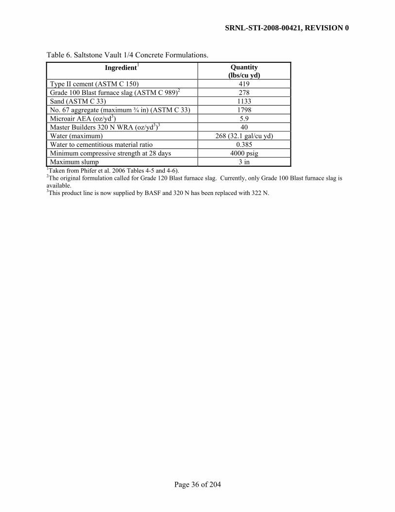
SRNL-STI-2008-00421, REVISION 0
Page 36 of 204
Table 6. Saltstone Vault 1/4 Concrete Formulations. Ingredient1 Quantity
(lbs/cu yd) Type II cement (ASTM C 150) 419 Grade 100 Blast furnace slag (ASTM C 989)2 278 Sand (ASTM C 33) 1133 No. 67 aggregate (maximum ¾ in) (ASTM C 33) 1798 Microair AEA (oz/yd3) 5.9 Master Builders 320 N WRA (oz/yd3)3 40 Water (maximum) 268 (32.1 gal/cu yd) Water to cementitious material ratio 0.385 Minimum compressive strength at 28 days 4000 psig Maximum slump 3 in
1Taken from Phifer et al. 2006 Tables 4-5 and 4-6). 2The original formulation called for Grade 120 Blast furnace slag. Currently, only Grade 100 Blast furnace slag is available. 3This product line is now supplied by BASF and 320 N has been replaced with 322 N.

SRNL-STI-2008-00421, REVISION 0
Page 37 of 204
Table 7. Ingredients Used to Prepare the Vault 1/4 Concrete Samples.
Material Specification Supplier / Address Phone Number Portland cement ASTM C 150 LaFarge Cement (Type I/II) P.O. Box 326
463 Judge St. (803) 462-7651 (706) 798-3676
Harleyville, S.C, 29448 sampled from Lafarge Ready Mix Plant, 109 Laney Walker Blvd., Augusta, GA, 30909
Slag cement (Grade 100) ASTM C 989 Holcim, US Inc. 1555 Hartman Industrial Blvd. Birmingham, AL 35221
(205) 929-6813
Concrete sand ASTM C 33 Foster Dixiana 3308 Charleston Hwy. Columbia, SC, 29172 sampled from Lafarge Ready Mix Plant, 109 Laney Walker Blvd., Augusta, GA, 30909
(803) 794-2872 (706) 798-3676
No. 67 stone 3/4 inch gravel (granite)
ASTM C 33 USA Aggregates Dogwood Quarry Appling GA, 30802 sampled from Lafarge Ready Mix Plant, 109 Laney Walker Blvd., Augusta, GA, 30909
(706) 541-0187 (706) 798-3676
Admixtures
Microair (air entraining admixture)
ASTM C 260 (864) 607-4160
322 N (mid range water reducer)1 ASTM C 494
BASF Corporation 106 Macon St. Reynolds, GA, 31076
1322 N has replaced 320 N in the BASF AEA product line.

SRNL-STI-2008-00421, REVISION 0
Page 38 of 204
Table 8. Saltstone Vault 2, Mix 1 Concrete Formulation (670 lbs/cu yd Cementitious Material, Class 3 Sulfate Resistant Concrete).
Ingredient1 Quantity (lbs/cu yd)
Type V cement (Lehigh T-V #2 ; ASTM C 150) 201 Grade 100 Blast furnace slag (Holcim Grade 100 Slag; ASTM C 989)
268
Silica Fume (W. R. Grace Silica Fume; ASTM C 1240) 44.7 Type F Fly ash (SEFA Class “F” Fly Ash; ASTM C 618) 156.3 sand (Rinker Aggregates Company - Augusta Sand - Natural Washed Sand); ASTM C 33)
911
aggregate (Rinker Aggregates Company - Dogwood Quarry - #67 Granite; ASTM C 33)
1850
Water (maximum) 254.6 Water (maximum; gal/ cu yd) 30.5 Maximum water to cementitious material ratio 0.38 Grace WRDA 35 (oz/cwt c+p) 5 Grace Darex II (oz/cwt c+p) 0.4 to 0.5 Grace Adva 380 (oz/cwt c+p) 3 to 4 Minimum compressive strength of at 28 days 5000 psig Slump range/target of before Super-P 1 – 3 inches / 2 inches Slump range/target of after Super-P 6 – 8 inches / 7 inches
1Taken from Phifer et al. 2006 Tables 4-6, DCR: AC51636A-001 Supplier Document, and personal correspondence with Carlos Chiappetto.

SRNL-STI-2008-00421, REVISION 0
Page 39 of 204
Table 9. Saltstone Vault 2, Mix 2 Concrete Formulation (710 lbs/cu yd Cementitious Material, Class 3 Sulfate Resistant Concrete).
Ingredient1 Quantity (lbs/cu yd)
Type V cement (Lehigh T-V #2 ; ASTM C 150) 213 Grade 100 Blast furnace slag (Holcim Grade 100 Slag; ASTM C 989)
284
Silica Fume (W. R. Grace Silica Fume; ASTM C 1240) 47.3 Type F Fly ash (SEFA Class “F” Fly Ash; ASTM C 618) 165.7 sand (Rinker Aggregates Company - Augusta Sand - Natural Washed Sand); ASTM C 33)
911
aggregate (Rinker Aggregates Company - Dogwood Quarry - #67 Granite; ASTM C 33)
1850
Water (maximum) 269.8 Water (maximum; gal/ cu yd) 32.3 Maximum water to cementitious material ratio 0.38 Grace WRDA 35 (oz/cwt c+p) 5 Grace Darex II (oz/cwt c+p) 0.4 to 0.5 Grace Adva 380 (oz/cwt c+p) 3 to 4 Minimum compressive strength of at 28 days 5000 psig Slump range/target of before Super-P 1 – 3 inches / 2 inches Slump range/target of after Super-P 6 – 8 inches / 7 inches
1Taken from Phifer et al. 2006 Tables 4-6, DCR: AC51636A-001 Supplier Document, and personal correspondence with Carlos Chiappetto.
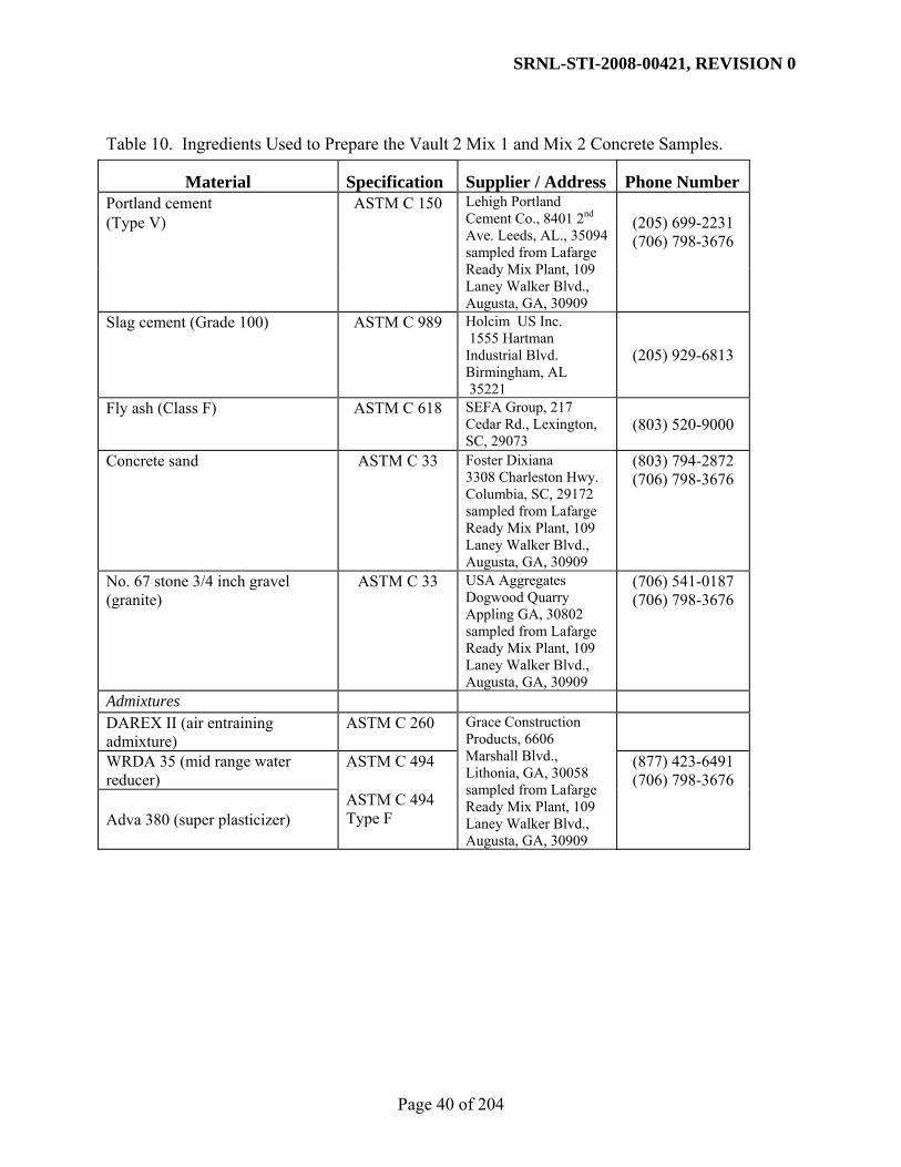
SRNL-STI-2008-00421, REVISION 0
Page 40 of 204
Table 10. Ingredients Used to Prepare the Vault 2 Mix 1 and Mix 2 Concrete Samples.
Material Specification Supplier / Address Phone Number Portland cement ASTM C 150 (Type V) (205) 699-2231
(706) 798-3676
Lehigh Portland Cement Co., 8401 2nd Ave. Leeds, AL., 35094 sampled from Lafarge Ready Mix Plant, 109 Laney Walker Blvd., Augusta, GA, 30909
Slag cement (Grade 100) ASTM C 989 Holcim US Inc. 1555 Hartman Industrial Blvd. Birmingham, AL 35221
(205) 929-6813
Fly ash (Class F) ASTM C 618 SEFA Group, 217 Cedar Rd., Lexington, SC, 29073
(803) 520-9000
Concrete sand ASTM C 33 Foster Dixiana 3308 Charleston Hwy. Columbia, SC, 29172 sampled from Lafarge Ready Mix Plant, 109 Laney Walker Blvd., Augusta, GA, 30909
(803) 794-2872 (706) 798-3676
No. 67 stone 3/4 inch gravel (granite)
ASTM C 33 USA Aggregates Dogwood Quarry Appling GA, 30802 sampled from Lafarge Ready Mix Plant, 109 Laney Walker Blvd., Augusta, GA, 30909
(706) 541-0187 (706) 798-3676
Admixtures DAREX II (air entraining admixture)
ASTM C 260
WRDA 35 (mid range water reducer)
ASTM C 494 (877) 423-6491 (706) 798-3676
Adva 380 (super plasticizer) ASTM C 494 Type F
Grace Construction Products, 6606 Marshall Blvd., Lithonia, GA, 30058 sampled from Lafarge Ready Mix Plant, 109 Laney Walker Blvd., Augusta, GA, 30909

SRNL-STI-2008-00421, REVISION 0
Page 41 of 204
Table 11. Fresh Properties of the DDA, ARP/MCU, and SWPF Saltstone.
Sample Id
Yield Stress (Pa)
Plastic Viscosity
(cP) Gel Time (minutes)
One Day Bleed (volume %)
Set Time (days)
DDA-TR430 6.3 89 > 90 5.0 2 MCU-TR436 3.4 79 40 1.5 1 SWPF-TR450 3.3 83 > 100 2.5 1
Table 12. Compressive Strength for the DDA Saltstone Grout (Cast 3/18/2008). Compressive Strength1,2
(psig) Days Aged Date Tested Measured Average
14 4/01/2008 820 790 790 80028 4/15/2008 910 940 900 91756 5/13/2008 1060 1070 1060 106390 6/16/2008 1020 1010 1040 1023
1Samples were 2-in cube mold samples and were tested per ASTM C 109. 2Lab Batch ID 080013.
Table 13. Compressive Strength for the ARP/MCU Saltstone Grout (Cast 3/31/2008). Compressive Strength1,2
(psig) Days Aged Date Tested Measured Average
16 4/16/2008 970 1000 820 93028 4/28/2008 1000 1000 1030 101056 5/26/2008 1130 1120 1170 114090 6/29/2008 1200 1230 1210 1213
1Samples were 2-in cube mold samples and were tested per ASTM C 109. 2Lab Batch ID 080014.
Table 14. Compressive Strength for the SWPF Saltstone Grout (Cast 4/22/2008). Compressive Strength1,2
(psig) Days Aged Date Tested Measured Average
14 5/06/2008 1020 1000 980 100028 5/20/2008 1210 1200 1230 121356 6/17/2008 1420 1420 1490 144390 7/21/2008 1480 1450 1470 1467
1Samples were 2-in cube mold samples and were tested per ASTM C 109. 2Lab Batch ID 080021.

SRNL-STI-2008-00421, REVISION 0
Page 42 of 204
Table 15. Compressive Strength for the Vault 1/4 Concrete (Cast 5/05/2008). Compressive Strength1,2
(psig) Days Aged Date Tested Measured Average
14 5/19/2008 7440 6870 715528 6/02/2008 8700 8750 872556 6/30/2008 10170 10230 10200 90 8/03/2008 9570 9290 9430
1Samples were 4 x 8 inch cylinders and were tested per ASTM C 39. 2Lab Batch ID 080025.
Table 16. Compressive Strength for the Vault 2 Mix 1 Concrete (Cast 3/25/2008). Compressive Strength1,2
(psig) Days Aged Date Tested Measured Average
14 4/08/2008 6390 6400 639528 4/22/2008 7550 7310 743056 5/20/2008 8050 8080 806590 6/23/2008 9450 9120 9285
1Samples were 4 x 8 inch cylinders and were tested per ASTM C 39. 2Lab Batch ID 080010.
Table 17. Compressive Strength for the Vault 2 Mix 2 Concrete (Cast 6/24/2008). Compressive Strength1,2
(psig) Days Aged Date Tested Measured Average
14 7/08/2008 6880 6800 684028 7/22/2008 8170 8340 825556 8/19/2008 9930 9560 974590 9/22/2008 10050 10260 10155
1Samples were 4 x 8 inch cylinders and were tested per ASTM C 39. 2Lab Batch ID 080028.

SRNL-STI-2008-00421, REVISION 0
Page 43 of 204
Table 18. Hydraulic Properties of DDA Saltstone as Measured by MCT.
Sample Id Sample Type
Minimum Curing Period (days)
Permeating Solution1
Saturated Hydraulic
Conductivity2
(cm/s) Permeability3
(darcy) DDA-TR430-1 2.8" Mold 28 DDA 1.4 x 10⁻⁸ 1.7 x 10⁻⁵
DDA-TR430-2 2.8" Mold 28 DDA 5.9 x 10⁻¹⁰ 7.1 x 10⁻⁷
DDA-TR430-3 2.8" Mold 28 DDA 2.0 x 10⁻⁹ 2.4 x 10⁻⁶
DDA-TR431-1 2.8" Mold 90 DDA 1.1 x 10⁻¹⁰ 1.3 x 10⁻⁷
DDA-TR431-2 2.8" Mold 90 DDA 7.2 x 10⁻¹¹ 8.7 x 10⁻⁸
DDA-TR431-3 2.8" Mold 90 DDA 1.1 x 10⁻¹⁰ 1.3 x 10⁻⁷ 1DDA permeant (Table 2) used as permeating solution. 2Saturated hydraulic conductivity relative to concentrated DDA simulant. 3Permeability is independent of the pore fluid and can be converted to saturated hydraulic conductivity for any solution using the equation in Section 3.3.1
Table 19. Physical Properties of DDA Saltstone as Measured by MCT.
Sample Id Sample Type
Minimum Curing Period (days)
Dry Bulk Density (g/cm3)1
Particle Density (g/cm3)2
Porosity3
DDA-TR430-1 2.8" Mold 28 1.04 2.36 0.56
DDA-TR430-2 2.8" Mold 28 1.05 2.39 0.56
DDA-TR430-3 2.8" Mold 28 1.04 2.40 0.56
DDA-TR431-1 2.8" Mold 90 1.05 2.34 0.55
DDA-TR431-2 2.8" Mold 90 1.08 2.48 0.57
DDA-TR431-3 2.8" Mold 90 1.06 2.38 0.56 1Dry bulk density corrected for salt precipitation as described in Section 3.3.1. 2Particle density calculated as ρs = ρb/(1-η) where ρb is dry bulk density and η is porosity. 3Porosity corrected for salt precipitation as described in Section 3.3.1.

SRNL-STI-2008-00421, REVISION 0
Page 44 of 204
Table 20. Hydraulic Properties of ARP/MCU Saltstone as Measured by MCT.
Sample Id Sample Type
Minimum Curing Period (days)
Permeating Solution1
Saturated Hydraulic
Conductivity2 (cm/s)
Permeability3
(darcy) MCU-TR436-1 2.8" Mold 28 ARP/MCU 5.4 x 10⁻⁹ 9.8 x 10⁻⁶
MCU-TR436-2 2.8" Mold 28 ARP/MCU 2.1 x 10⁻⁹ 3.8 x 10⁻⁶
MCU-TR436-3 2.8" Mold 28 ARP/MCU 2.7 x 10⁻¹⁰ 4.9 x 10⁻⁷
MCU-TR437-1 2.8" Mold 90 ARP/MCU 1.1 x 10⁻⁹ 2.0 x 10⁻⁶
MCU-TR437-2 2.8" Mold 90 ARP/MCU 8.8 x 10⁻¹⁰ 1.6 x 10⁻⁶
MCU-TR437-3 2.8" Mold 90 ARP/MCU 6.4 x 10⁻¹⁰ 1.2 x 10⁻⁶ 1ARP/MCU permeant (Table 3) used as permeating solution. 2Saturated hydraulic conductivity relative to the concentrated ARP/MCU simulant. 3Permeability is independent of the pore fluid and can be converted to saturated hydraulic conductivity for any solution using the equation in Section 3.3.1.
Table 21. Physical Properties of ARP/MCU Saltstone as Measured by MCT.
Sample Id Sample Type
Minimum Curing Period (days)
Dry Bulk Density (g/cm3)1
Particle Density (g/cm3)2
Porosity3
MCU-TR436-1 2.8" Mold 28 0.98 2.30 0.58
MCU-TR436-2 2.8" Mold 28 0.98 2.33 0.58
MCU-TR436-3 2.8" Mold 28 0.98 2.34 0.58
MCU-TR437-1 2.8" Mold 90 0.95 2.35 0.59
MCU-TR437-2 2.8" Mold 90 0.96 2.39 0.60
MCU-TR437-3 2.8" Mold 90 0.97 2.49 0.61 1Dry bulk density corrected for salt precipitation as described in Section 3.3.1. 2Particle density calculated as ρs = ρb/(1-η) where ρb is dry bulk density and η is porosity. 3Porosity corrected for salt precipitation as described in Section 3.3.1.
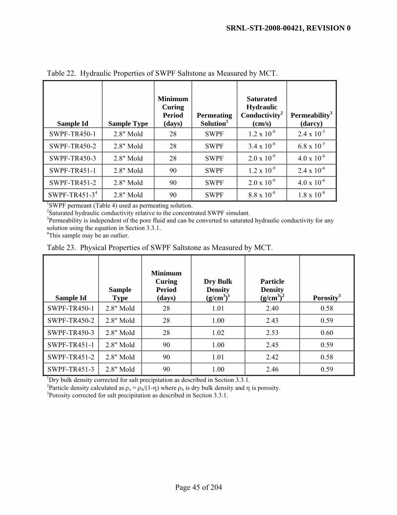
SRNL-STI-2008-00421, REVISION 0
Page 45 of 204
Table 22. Hydraulic Properties of SWPF Saltstone as Measured by MCT.
Sample Id Sample Type
Minimum Curing Period (days)
Permeating Solution1
Saturated Hydraulic
Conductivity2 (cm/s)
Permeability3
(darcy) SWPF-TR450-1 2.8" Mold 28 SWPF 1.2 x 10⁻⁸ 2.4 x 10⁻⁵
SWPF-TR450-2 2.8" Mold 28 SWPF 3.4 x 10⁻⁸ 6.8 x 10⁻⁵
SWPF-TR450-3 2.8" Mold 28 SWPF 2.0 x 10⁻⁹ 4.0 x 10⁻⁶
SWPF-TR451-1 2.8" Mold 90 SWPF 1.2 x 10⁻⁹ 2.4 x 10⁻⁶
SWPF-TR451-2 2.8" Mold 90 SWPF 2.0 x 10⁻⁹ 4.0 x 10⁻⁶
SWPF-TR451-34 2.8" Mold 90 SWPF 8.8 x 10⁻⁸ 1.8 x 10⁻⁸ 1SWPF permeant (Table 4) used as permeating solution. 2Saturated hydraulic conductivity relative to the concentrated SWPF simulant. 3Permeability is independent of the pore fluid and can be converted to saturated hydraulic conductivity for any solution using the equation in Section 3.3.1. 4This sample may be an outlier.
Table 23. Physical Properties of SWPF Saltstone as Measured by MCT.
Sample Id Sample Type
Minimum Curing Period (days)
Dry Bulk Density (g/cm3)1
Particle Density (g/cm3)2
Porosity3
SWPF-TR450-1 2.8" Mold 28 1.01 2.40 0.58
SWPF-TR450-2 2.8" Mold 28 1.00 2.43 0.59
SWPF-TR450-3 2.8" Mold 28 1.02 2.53 0.60
SWPF-TR451-1 2.8" Mold 90 1.00 2.45 0.59
SWPF-TR451-2 2.8" Mold 90 1.01 2.42 0.58
SWPF-TR451-3 2.8" Mold 90 1.00 2.46 0.59 1Dry bulk density corrected for salt precipitation as described in Section 3.3.1. 2Particle density calculated as ρs = ρb/(1-η) where ρb is dry bulk density and η is porosity. 3Porosity corrected for salt precipitation as described in Section 3.3.1.

SRNL-STI-2008-00421, REVISION 0
Page 46 of 204
Table 24. Hydraulic Properties of Vault 1/4 Concrete as Measured by MCT.
Sample Id Sample Type
Minimum Curing Period (days)
PermeatingSolution
Saturated Hydraulic
Conductivity (cm/s) Permeability
(darcy) V1-080025-4 6" Mold 28 Water 1.3 x 10⁻¹⁰ 1.3 x 10⁻⁸
V1-080025-5 6" Mold 28 Water 2.1 x 10⁻⁹ 2.2 x 10⁻⁷
V1-080025-6 6" Mold 28 Water 1.1 x 10⁻¹⁰ 1.1 x 10⁻⁸
Table 25. Physical Properties of Vault 1/4 Concrete as Measured by MCT.
Sample Id Sample Type
Minimum Curing Period (days)
Dry Bulk Density (g/cm3)
Particle Density (g/cm3)1
Porosity
V1-080025-4 6" Mold 28 2.27 2.57 0.12
V1-080025-5 6" Mold 28 2.31 2.58 0.10
V1-080025-6 6" Mold 28 2.27 2.55 0.10 1Particle density calculated as ρs = ρb/(1-η) where ρb is dry bulk density and η is porosity.

SRNL-STI-2008-00421, REVISION 0
Page 47 of 204
Table 26. Hydraulic Properties of Vault 2 Mix 1 Concrete as Measured by MCT.
Sample Id Sample Type
Minimum Curing Period (days)
PermeatingSolution
Saturated Hydraulic
Conductivity (cm/s) Permeability
(darcy) V2M1-080010-4 6" Mold 28 Water 7.8 x 10⁻¹¹ 8.0 x 10⁻⁹
V2M1-080010-5 6" Mold 28 Water 2.8 x 10⁻¹⁰ 2.9 x 10⁻⁸
V2M1-080010-6 6" Mold 28 Water 6.0 x 10⁻¹¹ 6.2 x 10⁻⁹
Table 27. Physical Properties of Vault 2 Mix 1 Concrete as Measured by MCT.
Sample Id Sample
Type
Minimum Curing Period (days)
Dry Bulk Density (g/cm3)
Particle Density (g/cm3)1
Porosity
V2M1-080010-4 6" Mold 28 2.18 2.47 0.12
V2M1-080010-5 6" Mold 28 2.21 2.39 0.08
V2M1-080010-6 6" Mold 28 2.16 2.49 0.13 1Particle density calculated as ρs = ρb/(1-η) where ρb is dry bulk density and η is porosity.

SRNL-STI-2008-00421, REVISION 0
Page 48 of 204
Table 28. Hydraulic Properties of Vault 2 Mix 2 Concrete as Measured by MCT.
Sample Id Sample Type
Minimum Curing Period (days)
PermeatingSolution
Saturated Hydraulic
Conductivity (cm/s) Permeability
(darcy) V2M2-080028-4 6" Mold 28 Water 5.0 x 10⁻¹¹ 5.2 x 10⁻⁹
V2M2-080028-5 6" Mold 28 Water 5.0 x 10⁻¹¹ 5.2 x 10⁻⁹
V2M2-080028-6 6" Mold 28 Water 3.2 x 10⁻¹⁰ 3.3 x 10⁻⁸
Table 29. Physical Properties of Vault 2 Mix 2 Concrete as Measured by MCT.
Sample Id Sample
Type
Minimum Curing Period (days)
Dry Bulk Density (g/cm3)
Particle Density (g/cm3)1
Porosity
V2M2-080028-4 6" Mold 28 2.16 2.50 0.14
V2M2-080028-5 6" Mold 28 2.17 2.43 0.09
V2M2-080028-6 6" Mold 28 2.21 2.46 0.10 1Particle density calculated as ρs = ρb/(1-η) where ρb is dry bulk density and η is porosity.

SRNL-STI-2008-00421, REVISION 0
Page 49 of 204
Table 30. Summary Hydraulic Properties for Saltstone and Vault Concrete Samples. Saturated
Hydraulic Conductivity1 (cm/sec)
Permeability (darcy)
Description
Minimum Curing Period (days) Minimum Maximum Arithmetic
Average Logarithmic
Average Minimum Maximum Arithmetic Average
Logarithmic Average
28 5.9 x 10⁻¹⁰ 1.4 x 10-08 5.5 x 10-09 2.5 x 10-09 7.1 x 10-07 1.7 x 10-05 6.7 x 10-06 3.1 x 10-06 DDA Saltstone
90 7.2 x 10⁻¹¹ 1.1 x 10⁻¹⁰ 9.7 x 10⁻¹¹ 9.6 x 10⁻¹¹ 8.7 x 10-08 1.3 x 10-07 1.2 x 10-07 1.1 x 10-07 28 2.7 x 10⁻¹⁰ 5.4 x 10-09 2.6 x 10-09 2.6 x 10-09 4.9 x 10-07 9.8 x 10-06 4.7 x 10-06 2.6 x 10-06 ARP/MCU
Saltstone 90 6.4 x 10⁻¹⁰ 1.1 x 10-09 8.7 x 10⁻¹⁰ 8.5 x 10⁻¹⁰ 1.2 x 10-06 2.0 x 10-06 1.6 x 10-06 1.6 x 10-06 28 2.0 x 10-09 3.4 x 10-08 1.6 x 10-08 9.3 x 10-09 4.0 x 10-06 6.8 x 10-05 3.2 x 10-05 1.9 x 10-05
SWPF Saltstone2 90 1.2 x 10-09 8.8 x 10-08 3.0 x 10-08
(1.6 x 10-09) 6.0 x 10-09
(1.5 x 10-09) 2.4 x 10-06 1.8 x 10-04 6.1 x 10-05 (3.2 x 10-06)
1.2 x 10-05 (3.1 x 10-06)
Vault 1/4 Concrete 28 1.1 x 10⁻¹⁰ 2.1 x 10-09 7.8 x 10⁻¹⁰ 3.1 x 10⁻¹⁰ 1.1 x 10-08 2.2 x 10-07 8.0 x 10-08 3.2 x 10-08
Vault 2 Mix 1 Concrete 28 6.0 x 10⁻¹¹ 2.8 x 10⁻¹⁰ 1.4 x 10⁻¹⁰ 1.1 x 10⁻¹⁰ 6.2 x 10-09 2.9 x 10-08 1.4 x 10-08 1.1 x 10-08
Vault 2 Mix 2 Concrete 28 5.0 x 10⁻¹¹ 3.2 x 10⁻¹⁰ 1.4 x 10⁻¹⁰ 9.3 x 10⁻¹¹ 5.2 x 10-09 3.3 x 10-08 1.4 x 10-08 9.6 x 10-09
1Saturated hydraulic conductivity values for saltstone materials are relative to the concentrated simulants as given in Table 5. The saturated hydraulic conductivity of the vault concretes are relative to tap water. 2The 90 day saturated hydraulic conductivity data may be influenced by an outlying value. If this value is excluded, the arithmetically averaged saturated hydraulic conductivity is 1.6 x 10⁻⁹ cm/sec and the logarithmically averaged saturated hydraulic conductivity is 1.5 x 10⁻⁹ cm/sec. If the value is also excluded for permeability, arithmetically averaged permeability is 3.2 x 10⁻⁶ darcy and the logarithmically averaged permeability is 3.1 x 10⁻⁶ darcy.

SRNL-STI-2008-00421, REVISION 0
Page 50 of 204
Table 31. Summary Physical Properties for Saltstone and Vault Concrete Samples. Bulk
Density (g/cm3)
Particle Density (g/cm3)
Porosity (fraction) Description
Minimum Curing Period (days) Minimum Maximum Arithmetic
Average Minimum Maximum Arithmetic Average Minimum Maximum Arithmetic
Average DDA
Saltstone 28 1.04 1.07 1.05 2.32 2.43 2.37 0.54 0.56 0.56
90 1.04 1.08 1.06 2.33 2.48 2.37 0.55 0.57 0.55 ARP/MCU Saltstone 28 0.98 0.99 0.98 2.30 2.41 2.35 0.58 0.59 0.58
90 0.95 1.01 0.97 2.30 2.49 2.38 0.58 0.61 0.59 SWPF
Saltstone 28 1.00 1.05 1.03 2.40 2.53 2.45 0.56 0.60 0.58
90 1.00 1.03 1.01 2.35 2.53 2.44 0.57 0.59 0.59 Vault 1/4 Concrete 28 2.15 2.31 2.24 2.44 2.58 2.53 0.10 0.12 0.11
Vault 2 Mix 1 Concrete 28 2.16 2.21 2.19 2.39 2.50 2.48 0.08 0.13 0.12
Vault 2 Mix 2 Concrete 28 2.16 2.26 2.22 2.43 2.55 2.50 0.09 0.14 0.11

SRNL-STI-2008-00421, REVISION 0
Page 51 of 204
Table 32. Moisture Retention Data for DDA Saltstone as measured by MCT. Potential
(cm) 0 -101.97 -509.87 -1,019.74 -5,098.72 -15,296.16
(0.00 bars) (-0.10 bars) (-0.50 bars) (-1.0 bars) (-5.0 bars) (-15.0 bars)
Volumetric Moisture Content1 Sample Id
Minimum Curing Period (days)
Bulk Density1 (g/cm3) (cm3/cm3)
DDA-TR430-1 28 1.07 0.560 0.558 0.557 0.557 0.556 0.556 DDA-TR430-2 28 1.06 0.545 0.544 0.544 0.543 0.542 0.542 DDA-TR430-3 28 1.06 0.545 0.544 0.543 0.542 0.541 0.541 DDA-TR431-1 90 1.06 0.551 0.550 0.549 0.548 0.548 0.546 DDA-TR431-2 90 1.06 0.550 0.545 0.544 0.543 0.543 0.542 DDA-TR431-3 90 1.04 0.553 0.550 0.549 0.549 0.549 0.547
1Dry bulk density and volumetric moisture content corrected for salt precipitation as described in Section 3.3.1.
Table 33. Moisture Retention Data for the ARP/MCU Saltstone as measured by MCT. Potential
(cm) 0 -101.97 -509.87 -1,019.74 -5,098.72 -15,296.16
(0.00 bars) (-0.10 bars) (-0.50 bars) (-1.0 bars) (-5.0 bars) (-15.0 bars)
Volumetric Moisture Content1 Sample Id
Minimum Curing Period (days)
Bulk Density1 (g/cm3) (cm3/cm3)
MCU-TR436-1 28 0.98 0.582 0.580 0.580 0.580 0.579 0.579 MCU-TR436-2 28 0.98 0.590 0.588 0.588 0.588 0.588 0.587 MCU-TR436-3 28 0.99 0.592 0.590 0.590 0.590 0.589 0.589 MCU-TR437-1 90 1.01 0.584 0.580 0.580 0.580 0.579 0.579 MCU-TR437-2 90 0.98 0.585 0.581 0.580 0.580 0.580 0.580 MCU-TR437-3 90 0.95 0.587 0.586 0.585 0.585 0.585 0.585
1Dry bulk density and volumetric moisture content corrected for salt precipitation as described in Section 3.3.1.

SRNL-STI-2008-00421, REVISION 0
Page 52 of 204
Table 34. Moisture Retention Data for the SWPF Saltstone as measured by MCT. Potential
(cm) 0 -101.97 -509.87 -1,019.74 -5,098.72 -15,296.16
(0.00 bars) (-0.10 bars) (-0.50 bars) (-1.0 bars) (-5.0 bars) (-15.0 bars)
Volumetric Moisture Content1 Sample Id
Minimum Curing Period (days)
Bulk Density1 (g/cm3) (cm3/cm3)
SWPF-TR450-1 28 1.05 0.576 0.575 0.575 0.574 0.574 0.574 SWPF-TR450-2 28 1.05 0.570 0.568 0.568 0.567 0.567 0.567 SWPF-TR450-3 28 1.05 0.566 0.563 0.563 0.562 0.562 0.562 SWPF-TR451-1 90 1.00 0.579 0.574 0.574 0.573 0.573 0.573 SWPF-TR451-2 90 1.03 0.599 0.593 0.592 0.592 0.592 0.591 SWPF-TR451-3 90 1.02 0.588 0.582 0.582 0.581 0.581 0.581 1Dry bulk density and volumetric moisture content corrected for salt precipitation as described in Section 3.3.1.
Table 35. Moisture Retention Data for Vault 1/4 Concrete as measured by MCT.
Potential (cm)
0 -101.97 -509.87 -1,019.74 -5,098.72 -15,296.16 (0.00 bars) (-0.10 bars) (-0.50 bars) (-1.0 bars) (-5.0 bars) (-15.0 bars)
Volumetric Moisture Content Sample Id
Minimum Curing Period (days)
Bulk Density (g/cm3) (cm3/cm3)
V1-080025-x 28 2.25 0.117 0.114 0.113 0.112 0.111 0.111 V1-080025-x 28 2.15 0.122 0.120 0.119 0.118 0.118 0.117 V1-080025-x 28 2.19 0.124 0.122 0.121 0.120 0.120 0.119

SRNL-STI-2008-00421, REVISION 0
Page 53 of 204
Table 36. Moisture Retention Data for Vault 2 Mix 1 Concrete as measured by MCT.
Potential (cm)
0 -101.97 -509.87 -1,019.74 -5,098.72 -15,296.16 (0.00 bars) (-0.10 bars) (-0.50 bars) (-1.0 bars) (-5.0 bars) (-15.0 bars)
Volumetric Moisture Content Sample Id
Minimum Curing Period (days)
Bulk Density (g/cm3) (cm3/cm3)
V2M1-080010-1 28 2.18 0.128 0.128 0.125 0.125 0.124 0.124 V2M1-080010-2 28 2.21 0.116 0.116 0.114 0.113 0.113 0.112 V2M1-080010-3 28 2.19 0.127 0.125 0.123 0.123 0.122 0.121
Table 37. Moisture Retention Data for Vault 2 Mix 2 Concrete as measured by MCT.
Potential (cm)
0 -101.97 -509.87 -1,019.74 -5,098.72 -15,296.16 (0.00 bars) (-0.10 bars) (-0.50 bars) (-1.0 bars) (-5.0 bars) (-15.0 bars)
Volumetric Moisture Content Sample Id
Minimum Curing Period (days)
Bulk Density (g/cm3) (cm3/cm3)
V2M2-080028-1 28 2.26 0.113 0.110 0.109 0.108 0.108 0.107 V2M2-080028-2 28 2.25 0.111 0.108 0.107 0.106 0.105 0.105 V2M2-080028-3 28 2.26 0.109 0.106 0.105 0.105 0.104 0.104

SRNL-STI-2008-00421, REVISION 0
Page 54 of 204
Table 38. Van Genuchten Transport Parameters.
Material θs
(cm3/cm-3) θr
(cm3/cm3) α
(1/cm) n m1 DDA Saltstone 0.570 0.540 0.150 1.03 0.0291
ARP/MCU Saltstone 0.590 0.585 0.150 1.23 0.1870 MCU Saltstone – INL2 0.700 0.550 0.0007 1.12 0.1071
SWPF Saltstone 0.580 0.572 0.150 1.30 0.2308 Vault 1/4 Concrete 0.121 0.115 0.054 1.27 0.2099
Vault 2 Mix 1 Concrete 0.124 0.119 0.006 1.65 0.3951 Vault 2 Mix 2 Concrete 0.111 0.104 0.077 1.24 0.1952
1Data analyzed using Mualem relationship between n and m where m = 1 – 1/n. 2Analysis of MCU saltstone previously reported by Dixon and Phifer (2007).
Table 39. Recommended Saltstone and Vault Concrete Hydraulic and Physical Parameter Values
Saltstone
Saturated Hydraulic
Conductivity 1,2 (cm/s)
Particle Density2 (g/cm3)
Dry Bulk Density3 (g/cm3)
Porosity3
Van Genuchten Transport
Parameters4 DDA 9.6 x 10⁻¹¹ 2.37 1.06 0.55 Appendix F
ARP/MCU 8.5 x 10⁻¹⁰ 2.38 0.97 0.59 Appendix F
SWPF5 6.0 x 10-09 (1.5 x 10-09) 2.42 1.01 0.58 Appendix F
Vault 1/4 3.1 x 10⁻¹⁰ 2.53 2.24 0.12 Appendix F
Vault 2 Mix 1 1.1 x 10⁻¹⁰ 2.50 2.21 0.12 Appendix F
Vault 2 Mix 2 9.3 x 10⁻¹¹ 2.50 2.22 0.11 Appendix F 1Saturated hydraulic conductivity values for saltstone materials are relative to the concentrated simulants as given in Table 5. The saturated hydraulic conductivity of the vault concretes are relative to tap water. 2Logarithmically averaged saturated hydraulic conductivity from Tables 20, 22, 24, 26, 28, and 30. Used 90 day data for saltstone and 28 day data for concrete. 2Particle density calculated as ρs = ρb/(1-η) where ρb is dry bulk density and η is porosity using 90 day data for saltstone and 28 day for concretes. 3Average dry bulk density and porosity from Tables 21, 23, 25, 27, 29, and 31. Used 90 day data for saltstone and 28 day data for concretes. 4Characteristic curve data is contained in Appendix F. 5The SWPF saturated hydraulic conductivity value provided in parenthesis is the recommended value excluding a potential outlying value. Sample SWPF-TR451-3 had a saturated hydraulic conductivity almost two orders of magnitude greater than that of the other two 90 day samples whereas the difference between the minimum and maximum saturated hydraulic conductivity values for the 90 day DDA and ARP/MCU samples was less than a factor of two. The testing laboratory reported that a prolonged power failure complicated the testing of this sample. Thus, it may be appropriate to exclude this sample from the data set for saturated hydraulic conductivity.

SRNL-STI-2008-00421, REVISION 0
Page 55 of 204
APPENDIX A. DEVELOPMENT OF SALTSTONE PERMEANTS

SRNL-STI-2008-00421, REVISION 0
Page 56 of 204

SRNL-STI-2008-00421, REVISION 0
Page 57 of 204

SRNL-STI-2008-00421, REVISION 0
Page 58 of 204
SRNL-STI-2008-00421, REVISION 0
Page 59 of 204
APPENDIX B. STRENGTH REPORTS

SRNL-STI-2008-00421, REVISION 0
Page 60 of 204
DDA Saltstone Strength Report Page 1

SRNL-STI-2008-00421, REVISION 0
Page 61 of 204
DDA Saltstone Strength Report Page 2

SRNL-STI-2008-00421, REVISION 0
Page 62 of 204
ARP/MCU Saltstone Strength Report Page 1

SRNL-STI-2008-00421, REVISION 0
Page 63 of 204
ARP/MCU Saltstone Strength Report Page 2

SRNL-STI-2008-00421, REVISION 0
Page 64 of 204
SWPF Saltstone Strength Report Page 1

SRNL-STI-2008-00421, REVISION 0
Page 65 of 204
SWPF Saltstone Strength Report Page 2

SRNL-STI-2008-00421, REVISION 0
Page 66 of 204
Vault 1/4 Strength Report Page 1

SRNL-STI-2008-00421, REVISION 0
Page 67 of 204
Vault 1/4 Concrete Strength Report Page 2

SRNL-STI-2008-00421, REVISION 0
Page 68 of 204
Vault 2 Mix 1 Concrete Strength Report Page 1

SRNL-STI-2008-00421, REVISION 0
Page 69 of 204
Vault 2 Mix 1 Concrete Strength Report Page 2

SRNL-STI-2008-00421, REVISION 0
Page 70 of 204
Vault 2 Mix 2 Concrete Strength Report Page 1
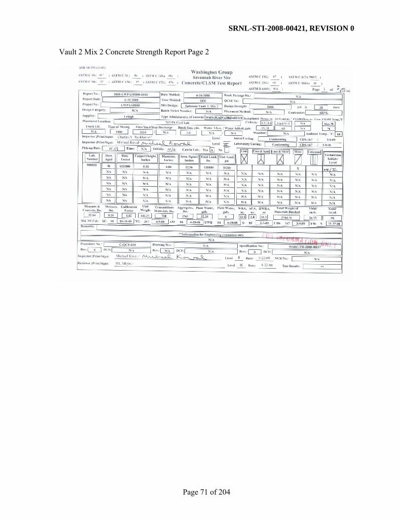
SRNL-STI-2008-00421, REVISION 0
Page 71 of 204
Vault 2 Mix 2 Concrete Strength Report Page 2

SRNL-STI-2008-00421, REVISION 0
Page 72 of 204
APPENDIX C. MCT DATA SHEETS ON SALTSTONE

SRNL-STI-2008-00421, REVISION 0
Page 73 of 204

SRNL-STI-2008-00421, REVISION 0
Page 74 of 204

SRNL-STI-2008-00421, REVISION 0
Page 75 of 204
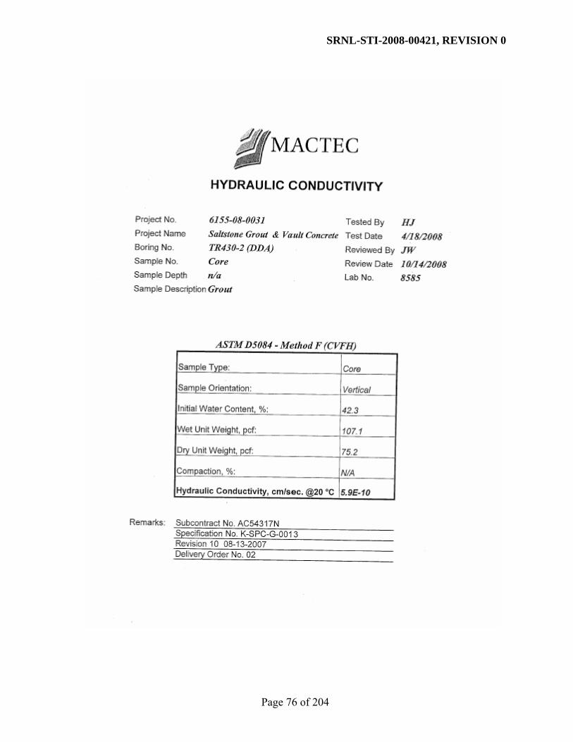
SRNL-STI-2008-00421, REVISION 0
Page 76 of 204

SRNL-STI-2008-00421, REVISION 0
Page 77 of 204

SRNL-STI-2008-00421, REVISION 0
Page 78 of 204
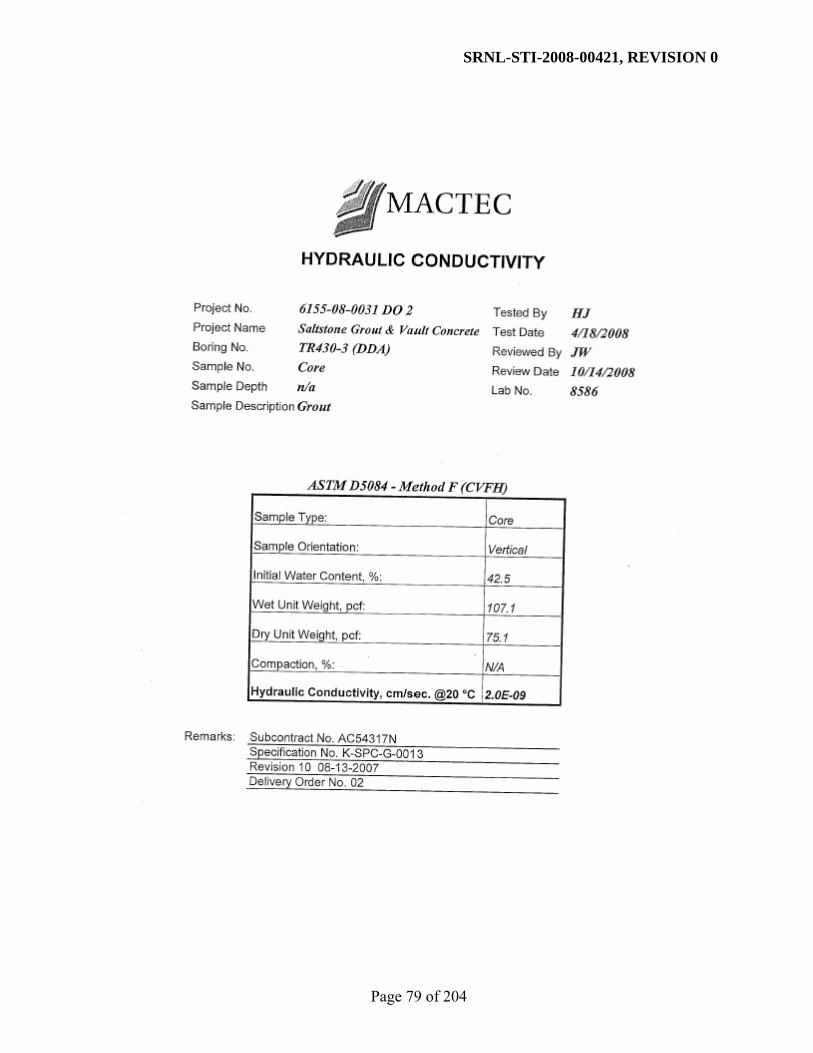
SRNL-STI-2008-00421, REVISION 0
Page 79 of 204

SRNL-STI-2008-00421, REVISION 0
Page 80 of 204

SRNL-STI-2008-00421, REVISION 0
Page 81 of 204

SRNL-STI-2008-00421, REVISION 0
Page 82 of 204

SRNL-STI-2008-00421, REVISION 0
Page 83 of 204

SRNL-STI-2008-00421, REVISION 0
Page 84 of 204

SRNL-STI-2008-00421, REVISION 0
Page 85 of 204

SRNL-STI-2008-00421, REVISION 0
Page 86 of 204

SRNL-STI-2008-00421, REVISION 0
Page 87 of 204

SRNL-STI-2008-00421, REVISION 0
Page 88 of 204

SRNL-STI-2008-00421, REVISION 0
Page 89 of 204

SRNL-STI-2008-00421, REVISION 0
Page 90 of 204

SRNL-STI-2008-00421, REVISION 0
Page 91 of 204

SRNL-STI-2008-00421, REVISION 0
Page 92 of 204

SRNL-STI-2008-00421, REVISION 0
Page 93 of 204

SRNL-STI-2008-00421, REVISION 0
Page 94 of 204

SRNL-STI-2008-00421, REVISION 0
Page 95 of 204

SRNL-STI-2008-00421, REVISION 0
Page 96 of 204

SRNL-STI-2008-00421, REVISION 0
Page 97 of 204

SRNL-STI-2008-00421, REVISION 0
Page 98 of 204

SRNL-STI-2008-00421, REVISION 0
Page 99 of 204
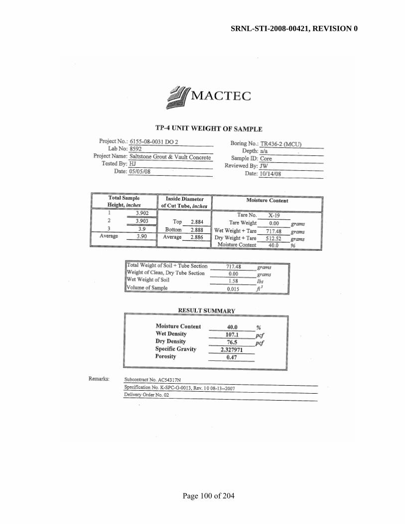
SRNL-STI-2008-00421, REVISION 0
Page 100 of 204

SRNL-STI-2008-00421, REVISION 0
Page 101 of 204

SRNL-STI-2008-00421, REVISION 0
Page 102 of 204

SRNL-STI-2008-00421, REVISION 0
Page 103 of 204

SRNL-STI-2008-00421, REVISION 0
Page 104 of 204

SRNL-STI-2008-00421, REVISION 0
Page 105 of 204

SRNL-STI-2008-00421, REVISION 0
Page 106 of 204

SRNL-STI-2008-00421, REVISION 0
Page 107 of 204

SRNL-STI-2008-00421, REVISION 0
Page 108 of 204

SRNL-STI-2008-00421, REVISION 0
Page 109 of 204
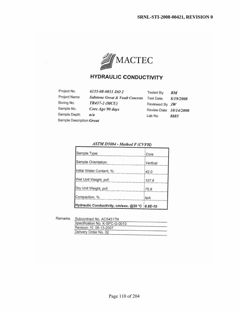
SRNL-STI-2008-00421, REVISION 0
Page 110 of 204

SRNL-STI-2008-00421, REVISION 0
Page 111 of 204

SRNL-STI-2008-00421, REVISION 0
Page 112 of 204

SRNL-STI-2008-00421, REVISION 0
Page 113 of 204
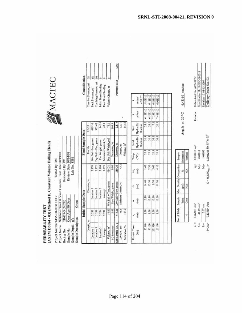
SRNL-STI-2008-00421, REVISION 0
Page 114 of 204

SRNL-STI-2008-00421, REVISION 0
Page 115 of 204

SRNL-STI-2008-00421, REVISION 0
Page 116 of 204

SRNL-STI-2008-00421, REVISION 0
Page 117 of 204
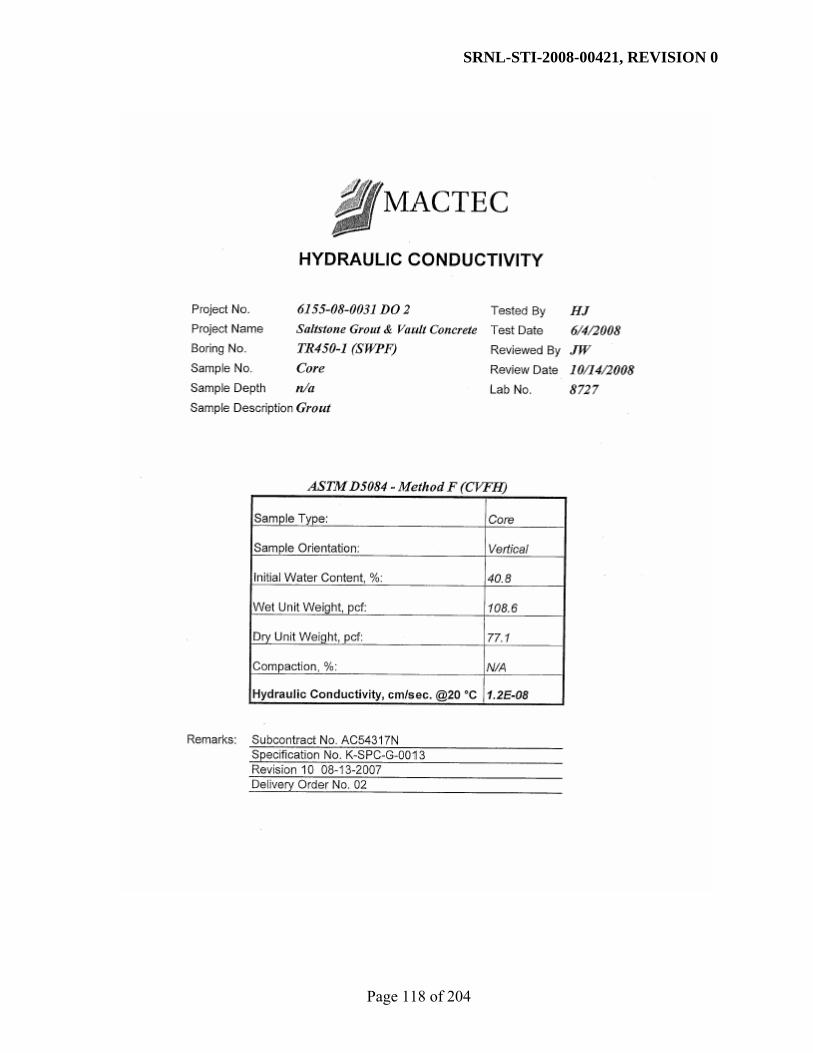
SRNL-STI-2008-00421, REVISION 0
Page 118 of 204

SRNL-STI-2008-00421, REVISION 0
Page 119 of 204

SRNL-STI-2008-00421, REVISION 0
Page 120 of 204

SRNL-STI-2008-00421, REVISION 0
Page 121 of 204

SRNL-STI-2008-00421, REVISION 0
Page 122 of 204

SRNL-STI-2008-00421, REVISION 0
Page 123 of 204

SRNL-STI-2008-00421, REVISION 0
Page 124 of 204

SRNL-STI-2008-00421, REVISION 0
Page 125 of 204

SRNL-STI-2008-00421, REVISION 0
Page 126 of 204

SRNL-STI-2008-00421, REVISION 0
Page 127 of 204

SRNL-STI-2008-00421, REVISION 0
Page 128 of 204

SRNL-STI-2008-00421, REVISION 0
Page 129 of 204

SRNL-STI-2008-00421, REVISION 0
Page 130 of 204

SRNL-STI-2008-00421, REVISION 0
Page 131 of 204

SRNL-STI-2008-00421, REVISION 0
Page 132 of 204

SRNL-STI-2008-00421, REVISION 0
Page 133 of 204

SRNL-STI-2008-00421, REVISION 0
Page 134 of 204

SRNL-STI-2008-00421, REVISION 0
Page 135 of 204

SRNL-STI-2008-00421, REVISION 0
Page 136 of 204

SRNL-STI-2008-00421, REVISION 0
Page 137 of 204

SRNL-STI-2008-00421, REVISION 0
Page 138 of 204

SRNL-STI-2008-00421, REVISION 0
Page 139 of 204
APPENDIX D. MCT DATA SHEETS ON VAULT CONCRETES

SRNL-STI-2008-00421, REVISION 0
Page 140 of 204

SRNL-STI-2008-00421, REVISION 0
Page 141 of 204

SRNL-STI-2008-00421, REVISION 0
Page 142 of 204

SRNL-STI-2008-00421, REVISION 0
Page 143 of 204

SRNL-STI-2008-00421, REVISION 0
Page 144 of 204

SRNL-STI-2008-00421, REVISION 0
Page 145 of 204

SRNL-STI-2008-00421, REVISION 0
Page 146 of 204

SRNL-STI-2008-00421, REVISION 0
Page 147 of 204

SRNL-STI-2008-00421, REVISION 0
Page 148 of 204

SRNL-STI-2008-00421, REVISION 0
Page 149 of 204

SRNL-STI-2008-00421, REVISION 0
Page 150 of 204

SRNL-STI-2008-00421, REVISION 0
Page 151 of 204

SRNL-STI-2008-00421, REVISION 0
Page 152 of 204

SRNL-STI-2008-00421, REVISION 0
Page 153 of 204

SRNL-STI-2008-00421, REVISION 0
Page 154 of 204
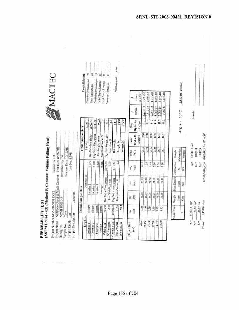
SRNL-STI-2008-00421, REVISION 0
Page 155 of 204

SRNL-STI-2008-00421, REVISION 0
Page 156 of 204

SRNL-STI-2008-00421, REVISION 0
Page 157 of 204
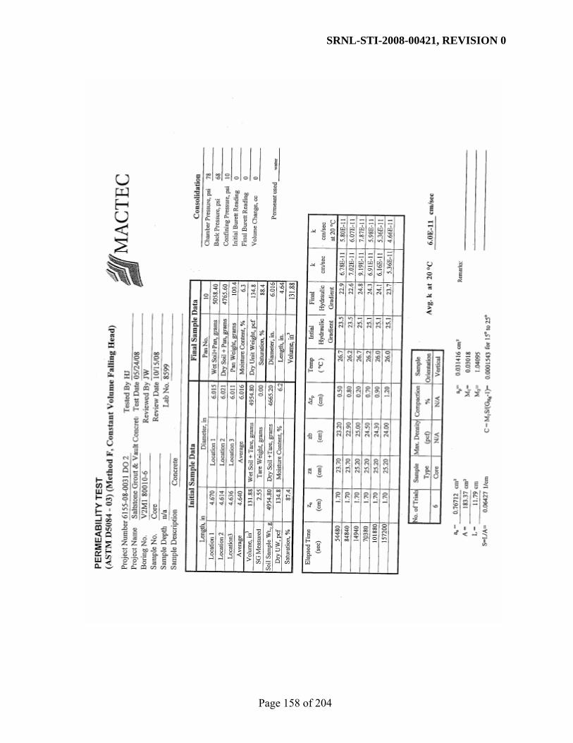
SRNL-STI-2008-00421, REVISION 0
Page 158 of 204

SRNL-STI-2008-00421, REVISION 0
Page 159 of 204

SRNL-STI-2008-00421, REVISION 0
Page 160 of 204
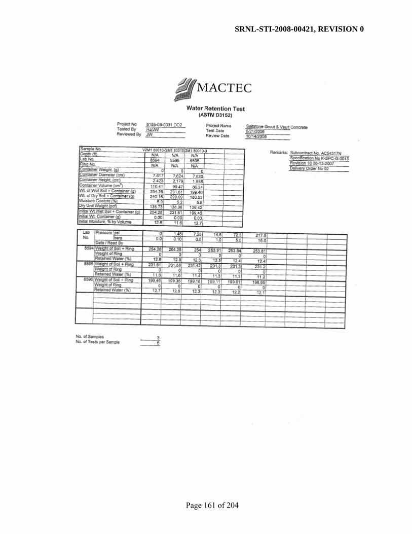
SRNL-STI-2008-00421, REVISION 0
Page 161 of 204
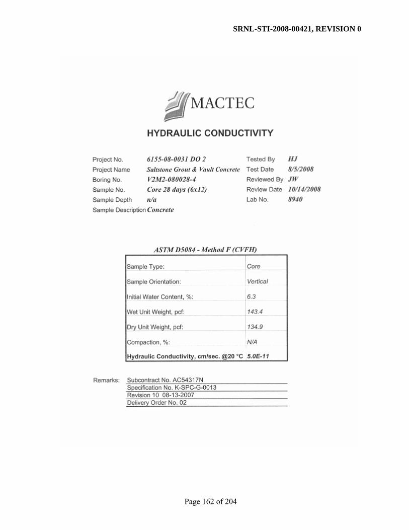
SRNL-STI-2008-00421, REVISION 0
Page 162 of 204
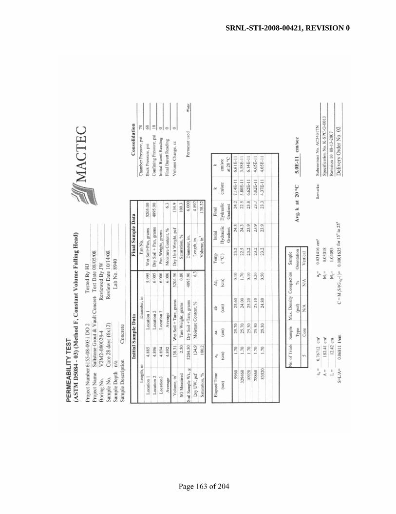
SRNL-STI-2008-00421, REVISION 0
Page 163 of 204

SRNL-STI-2008-00421, REVISION 0
Page 164 of 204

SRNL-STI-2008-00421, REVISION 0
Page 165 of 204

SRNL-STI-2008-00421, REVISION 0
Page 166 of 204

SRNL-STI-2008-00421, REVISION 0
Page 167 of 204

SRNL-STI-2008-00421, REVISION 0
Page 168 of 204

SRNL-STI-2008-00421, REVISION 0
Page 169 of 204

SRNL-STI-2008-00421, REVISION 0
Page 170 of 204

SRNL-STI-2008-00421, REVISION 0
Page 171 of 204

SRNL-STI-2008-00421, REVISION 0
Page 172 of 204

SRNL-STI-2008-00421, REVISION 0
Page 173 of 204
APPENDIX E. CALCULATIONS TO CORRECT FOR SALT PRECIPITATION

SRNL-STI-2008-00421, REVISION 0
Page 174 of 204
The purpose of this appendix is to demonstrate the calculations that were used to correct the raw laboratory measurements of dry bulk density, porosity, and moisture retention for the saltstone grout samples. For each of these measurements, the sample is ultimately oven dried and it is necessary to correct for salt precipitation that occurs during this process. For each type of saltstone, the amount of salt added per 100 gram of wet grout was measured and this information was used to make the corrections. The corrections were made for each of the three types of saltstone (DDA, ARP/MCU, SWPF). The example calculations presented are for DDA saltstone. However, the calculations were the same for each saltstone type except for the simulant ratios and properties. Dry bulk density was calculated based on the following equations.
total
liquidsatdry
drysatliquid
VMM
SMMM
−=
+−=
ρ
Mliquid = mass of interstitial liquid in sample Msat = mass of saturated sample Mdry = mass of oven dried sample S = known salt content of grout (g salt/100g grout) Vtotal = total volume of sample ρdry = dry bulk density
For sample DDA-TR430-1:
Msat = 542.84 g Mdry = 381.3 g S = 9.28 (grams of salt per 100 gram of grout) Vtotal = 318.24 cm3
3
3
04.1
24.31892.21184.542
92.211
84.542*100
28.93.38184.542
cmg
cmgg
gM
groutggroutgsaltgggM
dry
dry
liquid
liquid
=
−=
=
+−=
ρ
ρ

SRNL-STI-2008-00421, REVISION 0
Page 175 of 204
Porosity was calculated as:
total
liquid
total
voids
liquid
liquidliquid
VV
VV
MV
==
=
φ
ρ
Mliquid = mass of interstitial liquid in sample Vvoids = total volume of voids Vliquid = volume of interstitial liquid in sample Vtotal = total volume of sample ρliquid =density of interstitial liquid φ = corrected porosity
For sample DDA-TR430-1:
Mliquid = 211.92 g ρliquid = 1.19 g/cm3 Vtotal = 318.24 cm3
560.0
24.31808.178
08.178
19.1
92.211
3
3
3
3
=
=
=
=
=
φ
φ
ρ
cmcm
cmV
cmggV
MV
liquid
liquid
liquid
liquidliquid

SRNL-STI-2008-00421, REVISION 0
Page 176 of 204
The following equations were used to determine the initial moisture content (i.e., porosity) of the moisture retention samples. It is important to note that only the mass of liquid removed by oven drying needs to be corrected for salt precipitation. The liquid removed by pressure extraction does not need to be corrected. Therefore, to determine the mass of liquid initially in the sample, the calculation is broken into two parts. The first part of the calculation determines the mass of liquid removed by pressure extraction and the second part determines the mass of liquid removed by the oven drying process at the end of the test (which is corrected for salt precipitation). The sum of these two values equals the total mass of liquid in the sample at saturation. Corrections to the moisture retention data were slightly different than for porosity and dry bulk density. For these measurements, the water to simulant ratio was used rather than the measured salt content. Although the difference is negligible, some salt is lost during pressure extraction so the salt content of the grout prior to oven-drying is actually unknown. 1) Determine the initial moisture content of the sample:
total
liquid
total
voids
liquid
liquidliquid
ovenliquidpressureliquidliquid
wil
dryfinalpressureovenliquid
finalpressuresatpressureliquid
VV
VV
MV
MMM
MMM
MMM
==
=
+=
−=
−=
−−
−−
−−
φ
ρ
χ
Mliquid-pressure = mass of interstitial liquid removed by pressure extraction, g Mliquid-oven = mass of interstitial liquid removed by oven drying, g Mpressure-final = final mass of sample following pressure extraction, g Msat = total mass of saturated sample, g Mliquid = mass of interstitial liquid in sample at saturation, g Mdry = mass of oven dried sample, g χwil= mass fraction of water in interstitial liquid, fraction Vliquid = volume of interstitial liquid in sample, cm3
Vvoids = total volume of voids, cm3 Vtotal = total volume of sample, cm3 φ = porosity, fraction ρliquid =density of interstitial liquid, g/cm3

SRNL-STI-2008-00421, REVISION 0
Page 177 of 204
For DDA-TR430-1:
Msat = 156.54 g Mpressure-final = 156.08 g Mdry = 109.81 g χwil= 0.7767 Vtotal = 90.09 cm3 φ = porosity, fraction ρliquid =1.19 g/cm3
560.0
09.9045.50
45.50
19.1
03.60
03.60
57.5946.0
57.59
7767.081.10908.156
46.0
08.15654.156
3
3
3
3
=
=
=
=
=
+=
=
−=
=
−=
−
−
−
−
φ
φcmcm
cmV
cmggV
gM
ggM
gM
ggM
gM
ggM
liquid
liquid
liquid
liquid
ovenliquid
ovenliquid
pressureliquid
pressureliquid

SRNL-STI-2008-00421, REVISION 0
Page 178 of 204
2) Determine the volumetric moisture content of the samples at each pressure increment. In this example, the volumetric liquid content at 15 bars is determined.
total
liquidliquid
liquid
solidsampleliquid
liquidsatsolid
VV
MMV
MMM
=
−=
−=
θ
ρ
Msat = total mass of saturated sample, g Msample = mass of sample at each pressure increment, g Mliquid = mass of interstitial liquid in sample at saturation, g Msolid= corrected final dry weight of sample, g ρliquid =density of interstitial liquid, g/cm3 Vliquid = volume of liquid in sample at each pressure increment, cm3 Vtotal = total volume of sample, cm3 θliquid = volumetric moisture content of sample at each pressure increment, fraction

SRNL-STI-2008-00421, REVISION 0
Page 179 of 204
For DDA-TR430-1
Msat = 156.54 g Msample = mass of sample at each pressure increment, g Mliquid =60.03 g ρliquid =1.19 g/cm3 Vtotal = 90.09 cm3
556.0
09.9006.50
06.50
19.1
51.9608.156
51.96
03.6054.156
3
3
3
3
=
=
=
−=
=
−=
liquid
liquid
liquid
liquid
solid
solid
cmcm
cmV
cmg
ggV
gM
ggM
θ
θ

SRNL-STI-2008-00421, REVISION 0
Page 180 of 204
APPENDIX F. RECOMMENDED CHARACTERISTIC CURVE DATA

SRNL-STI-2008-00421, REVISION 0
Page 181 of 204
Table F.1. Recommended Characteristic Curves for the DDA Saltstone (w/pm 0.6).
Saturation
Suction Head (cm) Saturation
Relative Permeability
kr (Ksat = 9.6 x 10⁻¹¹ cm/s)
1.0000000000000E+00 0.00E+00 1.0000000000000E+00 1.000000E+00 9.9999010535498E-01 5.00E-02 9.9999010535498E-01 1.868055E-02 9.9997986436144E-01 1.00E-01 9.9997986436144E-01 1.409047E-02 9.9995916826836E-01 2.00E-01 9.9995916826836E-01 1.010657E-02 9.9989725297926E-01 5.00E-01 9.9989725297926E-01 5.857499E-03 9.9979724454104E-01 1.00E+00 9.9979724454104E-01 3.469996E-03 9.9961184597960E-01 2.00E+00 9.9961184597960E-01 1.807035E-03 9.9915465067191E-01 5.00E+00 9.9915465067191E-01 5.962337E-04 9.9860302333373E-01 1.00E+01 9.9860302333373E-01 2.111529E-04 9.9788067099630E-01 2.00E+01 9.9788067099630E-01 6.441829E-05 9.9674249020172E-01 5.00E+01 9.9674249020172E-01 1.144766E-05 9.9580897825690E-01 1.00E+02 9.9580897825690E-01 2.890764E-06 9.9485355143488E-01 2.00E+02 9.9485355143488E-01 7.080560E-07 9.9359026361135E-01 5.00E+02 9.9359026361135E-01 1.077786E-07 9.9264684578947E-01 1.00E+03 9.9264684578947E-01 2.573860E-08 9.9245840185135E-01 1.15E+03 9.9245840185135E-01 1.927454E-08 9.9227060867993E-01 1.32E+03 9.9227060867993E-01 1.443233E-08 9.9208348235218E-01 1.52E+03 9.9208348235218E-01 1.080560E-08 9.9189703632961E-01 1.75E+03 9.9189703632961E-01 8.089594E-09 9.9171128180992E-01 2.01E+03 9.9171128180992E-01 6.055838E-09 9.9152622803278E-01 2.31E+03 9.9152622803278E-01 4.533103E-09 9.9134188254552E-01 2.66E+03 9.9134188254552E-01 3.393081E-09 9.9115825143362E-01 3.06E+03 9.9115825143362E-01 2.539646E-09 9.9097533952056E-01 3.52E+03 9.9097533952056E-01 1.900795E-09 9.9079315054099E-01 4.05E+03 9.9079315054099E-01 1.422599E-09 9.9061168729063E-01 4.65E+03 9.9061168729063E-01 1.064675E-09 9.9043095175602E-01 5.35E+03 9.9043095175602E-01 7.967839E-10 9.9025094522666E-01 6.15E+03 9.9025094522666E-01 5.962858E-10 9.9007166839208E-01 7.08E+03 9.9007166839208E-01 4.462313E-10 9.8989312142561E-01 8.14E+03 9.8989312142561E-01 3.339323E-10 9.8971530405684E-01 9.36E+03 9.8971530405684E-01 2.498910E-10 9.8953821563413E-01 1.08E+04 9.8953821563413E-01 1.869982E-10 9.8936185517866E-01 1.24E+04 9.8936185517866E-01 1.399328E-10 9.8918622143100E-01 1.42E+04 9.8918622143100E-01 1.047123E-10 9.8901131289143E-01 1.64E+04 9.8901131289143E-01 7.835600E-11 9.8883712785458E-01 1.88E+04 9.8883712785458E-01 5.863323E-11 9.8866366443946E-01 2.16E+04 9.8866366443946E-01 4.387456E-11 9.8849092061527E-01 2.49E+04 9.8849092061527E-01 3.283065E-11 9.8831889422372E-01 2.86E+04 9.8831889422372E-01 2.456655E-11 9.8814758299825E-01 3.29E+04 9.8814758299825E-01 1.838261E-11 9.8797698458060E-01 3.79E+04 9.8797698458060E-01 1.375525E-11 9.8780709653512E-01 4.35E+04 9.8780709653512E-01 1.029269E-11 9.8763791636112E-01 5.01E+04 9.8763791636112E-01 7.701725E-12

SRNL-STI-2008-00421, REVISION 0
Page 182 of 204
Table F.1. Recommended Characteristic Curves for the DDA Saltstone (w/pm 0.6) continued.
Saturation
Suction Head (cm) Saturation
Relative Permeability
kr (Ksat = 9.6 x 10⁻¹¹ cm/s)
9.8746944150343E-01 5.76E+04 9.8746944150343E-01 5.762967E-12 9.8730166936164E-01 6.62E+04 9.8730166936164E-01 4.312246E-12 9.8713459729793E-01 7.61E+04 9.8713459729793E-01 3.226711E-12 9.8696822264388E-01 8.76E+04 9.8696822264388E-01 2.414438E-12 9.8680254270634E-01 1.01E+05 9.8680254270634E-01 1.806640E-12 9.8663755477250E-01 1.16E+05 9.8663755477250E-01 1.351844E-12 9.8647325611416E-01 1.33E+05 9.8647325611416E-01 1.011536E-12 9.8630964399154E-01 1.53E+05 9.8630964399154E-01 7.568946E-13 9.8614671565646E-01 1.76E+05 9.8614671565646E-01 5.663558E-13 9.8598446835513E-01 2.03E+05 9.8598446835513E-01 4.237825E-13 9.8582289933051E-01 2.33E+05 9.8582289933051E-01 3.171002E-13 9.8566200582437E-01 2.68E+05 9.8566200582437E-01 2.372738E-13 9.8550178507903E-01 3.08E+05 9.8550178507903E-01 1.775427E-13 9.8534223433890E-01 3.54E+05 9.8534223433890E-01 1.328482E-13 9.8518335085174E-01 4.07E+05 9.8518335085174E-01 9.940508E-14 9.8502513186981E-01 4.68E+05 9.8502513186981E-01 7.438087E-14 9.8486757465076E-01 5.39E+05 9.8486757465076E-01 5.565624E-14 9.8471067645852E-01 6.20E+05 9.8471067645852E-01 4.164534E-14 9.8455443456393E-01 7.13E+05 9.8455443456393E-01 3.116153E-14 9.8439884624536E-01 8.19E+05 9.8439884624536E-01 2.331692E-14 9.8424390878922E-01 9.42E+05 9.8424390878922E-01 1.744711E-14 9.8408961949036E-01 1.08E+06 9.8408961949036E-01 1.305497E-14 9.8393597565248E-01 1.25E+06 9.8393597565248E-01 9.768504E-15 9.8378297458839E-01 1.43E+06 9.8378297458839E-01 7.309375E-15 9.8363061362029E-01 1.65E+06 9.8363061362029E-01 5.469309E-15 9.8347889007999E-01 1.90E+06 9.8347889007999E-01 4.092461E-15 9.8332780130910E-01 2.18E+06 9.8332780130910E-01 3.062222E-15 9.8317734465911E-01 2.51E+06 9.8317734465911E-01 2.291336E-15 9.8302751749163E-01 2.88E+06 9.8302751749163E-01 1.714514E-15 9.8287831717839E-01 3.31E+06 9.8287831717839E-01 1.282901E-15 9.8272974110135E-01 3.81E+06 9.8272974110135E-01 9.599421E-16 9.8258178665277E-01 4.38E+06 9.8258178665277E-01 7.182855E-16 9.8243445123528E-01 5.04E+06 9.8243445123528E-01 5.374637E-16 9.8228773226185E-01 5.80E+06 9.8228773226185E-01 4.021621E-16 9.8214162715588E-01 6.67E+06 9.8214162715588E-01 3.009215E-16 9.8199613335117E-01 7.67E+06 9.8199613335117E-01 2.251673E-16 9.8185124829195E-01 8.82E+06 9.8185124829195E-01 1.684835E-16 9.8170696943287E-01 1.01E+07 9.8170696943287E-01 1.260693E-16 9.8156329423902E-01 1.17E+07 9.8156329423902E-01 9.433249E-17 9.8142022018586E-01 1.34E+07 9.8142022018586E-01 7.058514E-17 9.8127774475925E-01 1.54E+07 9.8127774475925E-01 5.281597E-17 9.8113586545544E-01 1.77E+07 9.8113586545544E-01 3.952003E-17 9.8099457978099E-01 2.04E+07 9.8099457978099E-01 2.957122E-17

SRNL-STI-2008-00421, REVISION 0
Page 183 of 204
Table F.1. Recommended Characteristic Curves for the DDA Saltstone (w/pm 0.6) continued.
Saturation
Suction Head (cm) Saturation
Relative Permeability
kr (Ksat = 9.6 x 10⁻¹¹ cm/s)
9.8085388525283E-01 2.35E+07 9.8085388525283E-01 2.212694E-17 9.8071377939814E-01 2.70E+07 9.8071377939814E-01 1.655668E-17 9.8057425975438E-01 3.10E+07 9.8057425975438E-01 1.238869E-17 9.8043532386925E-01 3.57E+07 9.8043532386925E-01 9.269947E-18 9.8029696930064E-01 4.10E+07 9.8029696930064E-01 6.936322E-18 9.8015919361661E-01 4.72E+07 9.8015919361661E-01 5.190166E-18 9.8002199439533E-01 5.43E+07 9.8002199439533E-01 3.883588E-18 9.7988536922510E-01 6.24E+07 9.7988536922510E-01 2.905930E-18 9.7974931570425E-01 7.18E+07 9.7974931570425E-01 2.174389E-18 9.7961383144113E-01 8.25E+07 9.7961383144113E-01 1.627006E-18 9.7947891405409E-01 9.49E+07 9.7947891405409E-01 1.217422E-18 9.7934456117141E-01 1.09E+08 9.7934456117141E-01 9.109470E-19 9.7921077043126E-01 1.25E+08 9.7921077043126E-01 6.816244E-19 9.7907753948171E-01 1.44E+08 9.7907753948171E-01 5.100316E-19 9.7894486598063E-01 1.66E+08 9.7894486598063E-01 3.816358E-19 9.7881274759569E-01 1.91E+08 9.7881274759569E-01 2.855625E-19 9.7868118200430E-01 2.19E+08 9.7868118200430E-01 2.136746E-19 9.7855016689358E-01 2.52E+08 9.7855016689358E-01 1.598840E-19 9.7841969996034E-01 2.90E+08 9.7841969996034E-01 1.196347E-19 9.7828977891098E-01 3.34E+08 9.7828977891098E-01 8.951770E-20 9.7816040146154E-01 3.84E+08 9.7816040146154E-01 6.698246E-20 9.7803156533756E-01 4.41E+08 9.7803156533756E-01 5.012022E-20 9.7790326827413E-01 5.08E+08 9.7790326827413E-01 3.750289E-20 9.7777550801580E-01 5.84E+08 9.7777550801580E-01 2.806188E-20 9.7764828231655E-01 6.71E+08 9.7764828231655E-01 2.099756E-20 9.7752158893977E-01 7.72E+08 9.7752158893977E-01 1.571162E-20 9.7739542565818E-01 8.88E+08 9.7739542565818E-01 1.175635E-20 9.7726979025383E-01 1.02E+09 9.7726979025383E-01 8.796800E-21

SRNL-STI-2008-00421, REVISION 0
Page 184 of 204
Table F.2. Recommended Characteristic Curves for the ARP/MCU Saltstone (w/pm 0.6).
Saturation
Suction Head (cm) Saturation
Relative Permeability
kr (Ksat = 8.5 x 10⁻¹⁰ cm/s)
1.0000000000000E+00 0.00E+00 1.0000000000000E+00 1.000000E+00 9.9999614841617E-01 5.00E-02 9.9999614841617E-01 4.563459E-01 9.9999098293979E-01 1.00E-01 9.9999098293979E-01 3.839188E-01 9.9997894439345E-01 2.00E-01 9.9997894439345E-01 3.073041E-01 9.9993605635663E-01 5.00E-01 9.9993605635663E-01 2.044476E-01 9.9985461139490E-01 1.00E+00 9.9985461139490E-01 1.318531E-01 9.9968139960062E-01 2.00E+00 9.9968139960062E-01 7.171879E-02 9.9919782556041E-01 5.00E+00 9.9919782556041E-01 2.216349E-02 9.9858987175287E-01 1.00E+01 9.9858987175287E-01 6.583447E-03 9.9783038201652E-01 2.00E+01 9.9783038201652E-01 1.531679E-03 9.9677727558239E-01 5.00E+01 9.9677727558239E-01 1.759306E-04 9.9604152427855E-01 1.00E+02 9.9604152427855E-01 3.130601E-05 9.9539044037874E-01 2.00E+02 9.9539044037874E-01 5.390587E-06 9.9466198490639E-01 5.00E+02 9.9466198490639E-01 5.159668E-07 9.9420117768092E-01 1.00E+03 9.9420117768092E-01 8.690415E-08 9.9411669350360E-01 1.15E+03 9.9411669350360E-01 6.066360E-08 9.9403485226565E-01 1.32E+03 9.9403485226565E-01 4.234350E-08 9.9395557581617E-01 1.52E+03 9.9395557581617E-01 2.955431E-08 9.9387878747403E-01 1.75E+03 9.9387878747403E-01 2.062691E-08 9.9380441216504E-01 2.01E+03 9.9380441216504E-01 1.439561E-08 9.9373237652116E-01 2.31E+03 9.9373237652116E-01 1.004642E-08 9.9366260894936E-01 2.66E+03 9.9366260894936E-01 7.011008E-09 9.9359503967569E-01 3.06E+03 9.9359503967569E-01 4.892592E-09 9.9352960076973E-01 3.52E+03 9.9352960076973E-01 3.414199E-09 9.9346622615315E-01 4.05E+03 9.9346622615315E-01 2.382491E-09 9.9340485159577E-01 4.65E+03 9.9340485159577E-01 1.662522E-09 9.9334541470167E-01 5.35E+03 9.9334541470167E-01 1.160108E-09 9.9328785488761E-01 6.15E+03 9.9328785488761E-01 8.095151E-10 9.9323211335534E-01 7.08E+03 9.9323211335534E-01 5.648691E-10 9.9317813305939E-01 8.14E+03 9.9317813305939E-01 3.941554E-10 9.9312585867140E-01 9.36E+03 9.9312585867140E-01 2.750329E-10 9.9307523654191E-01 1.08E+04 9.9307523654191E-01 1.919108E-10 9.9302621466044E-01 1.24E+04 9.9302621466044E-01 1.339098E-10 9.9297874261435E-01 1.42E+04 9.9297874261435E-01 9.343809E-11 9.9293277154706E-01 1.64E+04 9.9293277154706E-01 6.519797E-11 9.9288825411596E-01 1.88E+04 9.9288825411596E-01 4.549284E-11 9.9284514445034E-01 2.16E+04 9.9284514445034E-01 3.174323E-11 9.9280339810957E-01 2.49E+04 9.9280339810957E-01 2.214922E-11 9.9276297204176E-01 2.86E+04 9.9276297204176E-01 1.545486E-11 9.9272382454296E-01 3.29E+04 9.9272382454296E-01 1.078378E-11 9.9268591521710E-01 3.79E+04 9.9268591521710E-01 7.524482E-12 9.9264920493672E-01 4.35E+04 9.9264920493672E-01 5.250272E-12 9.9261365580457E-01 5.01E+04 9.9261365580457E-01 3.663420E-12

SRNL-STI-2008-00421, REVISION 0
Page 185 of 204
Table F.2. Recommended Characteristic Curves for the ARP/MCU Saltstone (w/pm 0.6) continued.
Saturation
Suction Head (cm) Saturation
Relative Permeability
kr (Ksat = 8.5 x 10⁻¹⁰ cm/s)
9.9257923111605E-01 5.76E+04 9.9257923111605E-01 2.556179E-12 9.9254589532266E-01 6.62E+04 9.9254589532266E-01 1.783592E-12 9.9251361399633E-01 7.61E+04 9.9251361399633E-01 1.244514E-12 9.9248235379475E-01 8.76E+04 9.9248235379475E-01 8.683676E-13 9.9245208242764E-01 1.01E+05 9.9245208242764E-01 6.059091E-13 9.9242276862395E-01 1.16E+05 9.9242276862395E-01 4.227768E-13 9.9239438210007E-01 1.33E+05 9.9239438210007E-01 2.949951E-13 9.9236689352888E-01 1.53E+05 9.9236689352888E-01 2.058345E-13 9.9234027450981E-01 1.76E+05 9.9234027450981E-01 1.436222E-13 9.9231449753973E-01 2.03E+05 9.9231449753973E-01 1.002132E-13 9.9228953598472E-01 2.33E+05 9.9228953598472E-01 6.992434E-14 9.9226536405278E-01 2.68E+05 9.9226536405278E-01 4.879010E-14 9.9224195676726E-01 3.08E+05 9.9224195676726E-01 3.404356E-14 9.9221928994121E-01 3.54E+05 9.9221928994121E-01 2.375408E-14 9.9219734015242E-01 4.07E+05 9.9219734015242E-01 1.657454E-14 9.9217608471936E-01 4.68E+05 9.9217608471936E-01 1.156497E-14 9.9215550167778E-01 5.39E+05 9.9215550167778E-01 8.069520E-15 9.9213556975803E-01 6.20E+05 9.9213556975803E-01 5.630550E-15 9.9211626836316E-01 7.13E+05 9.9211626836316E-01 3.928746E-15 9.9209757754767E-01 8.19E+05 9.9209757754767E-01 2.741303E-15 9.9207947799691E-01 9.42E+05 9.9207947799691E-01 1.912759E-15 9.9206195100712E-01 1.08E+06 9.9206195100712E-01 1.334637E-15 9.9204497846618E-01 1.25E+06 9.9204497846618E-01 9.312502E-16 9.9202854283486E-01 1.43E+06 9.9202854283486E-01 6.497847E-16 9.9201262712871E-01 1.65E+06 9.9201262712871E-01 4.533907E-16 9.9199721490056E-01 1.90E+06 9.9199721490056E-01 3.163557E-16 9.9198229022347E-01 2.18E+06 9.9198229022347E-01 2.207388E-16 9.9196783767432E-01 2.51E+06 9.9196783767432E-01 1.540217E-16 9.9195384231787E-01 2.88E+06 9.9195384231787E-01 1.074694E-16 9.9194028969133E-01 3.31E+06 9.9194028969133E-01 7.498734E-17 9.9192716578939E-01 3.81E+06 9.9192716578939E-01 5.232280E-17 9.9191445704981E-01 4.38E+06 9.9191445704981E-01 3.650851E-17 9.9190215033933E-01 5.04E+06 9.9190215033933E-01 2.547400E-17 9.9189023294018E-01 5.80E+06 9.9189023294018E-01 1.777462E-17 9.9187869253687E-01 6.67E+06 9.9187869253687E-01 1.240233E-17 9.9186751720351E-01 7.67E+06 9.9186751720351E-01 8.653790E-18 9.9185669539146E-01 8.82E+06 9.9185669539146E-01 6.038227E-18 9.9184621591742E-01 1.01E+07 9.9184621591742E-01 4.213204E-18 9.9183606795184E-01 1.17E+07 9.9183606795184E-01 2.939785E-18 9.9182624100778E-01 1.34E+07 9.9182624100778E-01 2.051250E-18 9.9181672493003E-01 1.54E+07 9.9181672493003E-01 1.431270E-18 9.9180750988461E-01 1.77E+07 9.9180750988461E-01 9.986763E-19 9.9179858634865E-01 2.04E+07 9.9179858634865E-01 6.968315E-19

SRNL-STI-2008-00421, REVISION 0
Page 186 of 204
Table F.2. Recommended Characteristic Curves for the ARP/MCU Saltstone (w/pm 0.6) continued.
Saturation
Suction Head (cm) Saturation
Relative Permeability
kr (Ksat = 8.5 x 10⁻¹⁰ cm/s)
9.9178994510053E-01 2.35E+07 9.9178994510053E-01 4.862178E-19 9.9178157721032E-01 2.70E+07 9.9178157721032E-01 3.392610E-19 9.9177347403062E-01 3.10E+07 9.9177347403062E-01 2.367211E-19 9.9176562718754E-01 3.57E+07 9.9176562718754E-01 1.651734E-19 9.9175802857211E-01 4.10E+07 9.9175802857211E-01 1.152506E-19 9.9175067033189E-01 4.72E+07 9.9175067033189E-01 8.041669E-20 9.9174354486282E-01 5.43E+07 9.9174354486282E-01 5.611115E-20 9.9173664480141E-01 6.24E+07 9.9173664480141E-01 3.915184E-20 9.9172996301709E-01 7.18E+07 9.9172996301709E-01 2.731840E-20 9.9172349260487E-01 8.25E+07 9.9172349260487E-01 1.906156E-20 9.9171722687818E-01 9.49E+07 9.9171722687818E-01 1.330030E-20 9.9171115936199E-01 1.09E+08 9.9171115936199E-01 9.280355E-21 9.9170528378609E-01 1.25E+08 9.9170528378609E-01 6.475418E-21 9.9169959407864E-01 1.44E+08 9.9169959407864E-01 4.518252E-21 9.9169408435984E-01 1.66E+08 9.9169408435984E-01 3.152637E-21 9.9168874893592E-01 1.91E+08 9.9168874893592E-01 2.199769E-21 9.9168358229324E-01 2.19E+08 9.9168358229324E-01 1.534899E-21 9.9167857909254E-01 2.52E+08 9.9167857909254E-01 1.070983E-21 9.9167373416349E-01 2.90E+08 9.9167373416349E-01 7.472848E-22 9.9166904249932E-01 3.34E+08 9.9166904249932E-01 5.214209E-22 9.9166449925162E-01 3.84E+08 9.9166449925162E-01 3.638252E-22 9.9166009972539E-01 4.41E+08 9.9166009972539E-01 2.538604E-22 9.9165583937412E-01 5.08E+08 9.9165583937412E-01 1.771325E-22 9.9165171379515E-01 5.84E+08 9.9165171379515E-01 1.235952E-22 9.9164771872507E-01 6.71E+08 9.9164771872507E-01 8.623882E-23 9.9164385003536E-01 7.72E+08 9.9164385003536E-01 6.017355E-23 9.9164010372809E-01 8.88E+08 9.9164010372809E-01 4.198672E-23 9.9163647593180E-01 1.02E+09 9.9163647593180E-01 2.929657E-23

SRNL-STI-2008-00421, REVISION 0
Page 187 of 204
Table F.3. Characteristic Curves for MCU Saltstone as Determined by INL (Dixon and Phifer, 2007).
Saturation
Suction Head (cm) Saturation
Relative Permeability
kr (Ksat = 8.5 x 10⁻¹⁰ cm/s)
1.0000000000000E+00 0.00E+00 1.0000000000000E+00 1.000000E+00 9.9999976540962E-01 5.00E-02 9.9999976540962E-01 5.013543E-01 9.9999949012830E-01 1.00E-01 9.9999949012830E-01 4.661379E-01 9.9999889182528E-01 2.00E-01 9.9999889182528E-01 4.293214E-01 9.9999690770961E-01 5.00E-01 9.9999690770961E-01 3.784173E-01 9.9999327958840E-01 1.00E+00 9.9999327958840E-01 3.384701E-01 9.9998539616530E-01 2.00E+00 9.9998539616530E-01 2.975922E-01 9.9995927265626E-01 5.00E+00 9.9995927265626E-01 2.427984E-01 9.9991158215229E-01 1.00E+01 9.9991158215229E-01 2.014672E-01 9.9980830517116E-01 2.00E+01 9.9980830517116E-01 1.610389E-01 9.9946943274209E-01 5.00E+01 9.9946943274209E-01 1.106641E-01 9.9886370262499E-01 1.00E+02 9.9886370262499E-01 7.655804E-02 9.9760553368456E-01 2.00E+02 9.9760553368456E-01 4.768905E-02 9.9391355248690E-01 5.00E+02 9.9391355248690E-01 2.027161E-02 9.8853487285773E-01 1.00E+03 9.8853487285773E-01 8.443452E-03 9.8710980336367E-01 1.15E+03 9.8710980336367E-01 6.889821E-03 9.8556558070136E-01 1.32E+03 9.8556558070136E-01 5.571507E-03 9.8390345422771E-01 1.52E+03 9.8390345422771E-01 4.465546E-03 9.8212648862780E-01 1.75E+03 9.8212648862780E-01 3.548212E-03 9.8023949270192E-01 2.01E+03 9.8023949270192E-01 2.795807E-03 9.7824886091039E-01 2.31E+03 9.7824886091039E-01 2.185379E-03 9.7616234144880E-01 2.66E+03 9.7616234144880E-01 1.695324E-03 9.7398875142640E-01 3.06E+03 9.7398875142640E-01 1.305835E-03 9.7173766335656E-01 3.52E+03 9.7173766335656E-01 9.991959E-04 9.6941908735370E-01 4.05E+03 9.6941908735370E-01 7.599136E-04 9.6704317059299E-01 4.65E+03 9.6704317059299E-01 5.747188E-04 9.6461993065739E-01 5.35E+03 9.6461993065739E-01 4.324618E-04 9.6215903350220E-01 6.15E+03 9.6215903350220E-01 3.239348E-04 9.5966962095117E-01 7.08E+03 9.5966962095117E-01 2.416526E-04 9.5716018766385E-01 8.14E+03 9.5716018766385E-01 1.796153E-04 9.5463850379725E-01 9.36E+03 9.5463850379725E-01 1.330738E-04 9.5211157722331E-01 1.08E+04 9.5211157722331E-01 9.831164E-05 9.4958564802628E-01 1.24E+04 9.4958564802628E-01 7.244861E-05 9.4706620783297E-01 1.42E+04 9.4706620783297E-01 5.327253E-05 9.4455803702691E-01 1.64E+04 9.4455803702691E-01 3.909721E-05 9.4206525379006E-01 1.88E+04 9.4206525379006E-01 2.864607E-05 9.3959136998183E-01 2.16E+04 9.3959136998183E-01 2.095831E-05 9.3713934994577E-01 2.49E+04 9.3713934994577E-01 1.531453E-05 9.3471166933090E-01 2.86E+04 9.3471166933090E-01 1.117842E-05 9.3231037187351E-01 3.29E+04 9.3231037187351E-01 8.151749E-06 9.2993712278898E-01 3.79E+04 9.2993712278898E-01 5.939786E-06 9.2759325797390E-01 4.35E+04 9.2759325797390E-01 4.325028E-06 9.2527982863288E-01 5.01E+04 9.2527982863288E-01 3.147367E-06

SRNL-STI-2008-00421, REVISION 0
Page 188 of 204
Table F.3. Characteristic Curves for MCU Saltstone as Determined by INL continued (Dixon and Phifer, 2007).
Saturation
Suction Head (cm) Saturation
Relative Permeability
kr (Ksat = 8.5 x 10⁻¹⁰ cm/s)
9.2299764124261E-01 5.76E+04 9.2299764124261E-01 2.289194E-06 9.2074729297073E-01 6.62E+04 9.2074729297073E-01 1.664279E-06 9.1852920279901E-01 7.61E+04 9.1852920279901E-01 1.209497E-06 9.1634363867811E-01 8.76E+04 9.1634363867811E-01 8.787039E-07 9.1419074107923E-01 1.01E+05 9.1419074107923E-01 6.382032E-07 9.1207054331820E-01 1.16E+05 9.1207054331820E-01 4.634166E-07 9.0998298901970E-01 1.33E+05 9.0998298901970E-01 3.364304E-07 9.0792794706904E-01 1.53E+05 9.0792794706904E-01 2.441983E-07 9.0590522437266E-01 1.76E+05 9.0590522437266E-01 1.772249E-07 9.0391457671848E-01 2.03E+05 9.0391457671848E-01 1.286030E-07 9.0195571799659E-01 2.33E+05 9.0195571799659E-01 9.331025E-08 9.0002832801077E-01 2.68E+05 9.0002832801077E-01 6.769659E-08 8.9813205908321E-01 3.08E+05 8.9813205908321E-01 4.910991E-08 8.9626654162840E-01 3.54E+05 8.9626654162840E-01 3.562390E-08 8.9443138884901E-01 4.07E+05 8.9443138884901E-01 2.583975E-08 8.9262620068522E-01 4.68E+05 8.9262620068522E-01 1.874187E-08 8.9085056713049E-01 5.39E+05 8.9085056713049E-01 1.359311E-08 8.8910407101055E-01 6.20E+05 8.8910407101055E-01 9.858455E-09 8.8738629030804E-01 7.13E+05 8.8738629030804E-01 7.149654E-09 8.8569680010327E-01 8.19E+05 8.8569680010327E-01 5.185008E-09 8.8403517419068E-01 9.42E+05 8.8403517419068E-01 3.760138E-09 8.8240098642187E-01 1.08E+06 8.8240098642187E-01 2.726776E-09 8.8079381181805E-01 1.25E+06 8.8079381181805E-01 1.977370E-09 8.7921322748836E-01 1.43E+06 8.7921322748836E-01 1.433904E-09 8.7765881338479E-01 1.65E+06 8.7765881338479E-01 1.039793E-09 8.7613015291968E-01 1.90E+06 8.7613015291968E-01 7.539957E-10 8.7462683346769E-01 2.18E+06 8.7462683346769E-01 5.467478E-10 8.7314844677091E-01 2.51E+06 8.7314844677091E-01 3.964623E-10 8.7169458926244E-01 2.88E+06 8.7169458926244E-01 2.874841E-10 8.7026486232183E-01 3.31E+06 8.7026486232183E-01 2.084603E-10 8.6885887247339E-01 3.81E+06 8.6885887247339E-01 1.511579E-10 8.6747623153657E-01 4.38E+06 8.6747623153657E-01 1.096065E-10 8.6611655673647E-01 5.04E+06 8.6611655673647E-01 7.947680E-11 8.6477947078092E-01 5.80E+06 8.6477947078092E-01 5.762927E-11 8.6346460190973E-01 6.67E+06 8.6346460190973E-01 4.178734E-11 8.6217158392090E-01 7.67E+06 8.6217158392090E-01 3.030019E-11 8.6090005617747E-01 8.82E+06 8.6090005617747E-01 2.197076E-11 8.5964966359855E-01 1.01E+07 8.5964966359855E-01 1.593105E-11 8.5842005663725E-01 1.17E+07 8.5842005663725E-01 1.155162E-11 8.5721089124767E-01 1.34E+07 8.5721089124767E-01 8.376080E-12 8.5602182884320E-01 1.54E+07 8.5602182884320E-01 6.073491E-12 8.5485253624744E-01 1.77E+07 8.5485253624744E-01 4.403881E-12 8.5370268563944E-01 2.04E+07 8.5370268563944E-01 3.193246E-12

SRNL-STI-2008-00421, REVISION 0
Page 189 of 204
Table F.3. Characteristic Curves for the MCU Saltstone as Determined by INL continued (Dixon and Phifer, 2007).
Saturation
Suction Head (cm) Saturation
Relative Permeability
kr (Ksat = 8.5 x 10⁻¹⁰ cm/s)
8.5257195449417E-01 2.35E+07 8.5257195449417E-01 2.315416E-12 8.5146002551930E-01 2.70E+07 8.5146002551930E-01 1.678902E-12 8.5036658658906E-01 3.10E+07 8.5036658658906E-01 1.217367E-12 8.4929133067594E-01 3.57E+07 8.4929133067594E-01 8.827089E-13 8.4823395578063E-01 4.10E+07 8.4823395578063E-01 6.400492E-13 8.4719416486084E-01 4.72E+07 8.4719416486084E-01 4.640973E-13 8.4617166575932E-01 5.43E+07 8.4617166575932E-01 3.365152E-13 8.4516617113141E-01 6.24E+07 8.4516617113141E-01 2.440058E-13 8.4417739837237E-01 7.18E+07 8.4417739837237E-01 1.769276E-13 8.4320506954476E-01 8.25E+07 8.4320506954476E-01 1.282895E-13 8.4224891130609E-01 9.49E+07 8.4224891130609E-01 9.302213E-14 8.4130865483672E-01 1.09E+08 8.4130865483672E-01 6.744993E-14 8.4038403576840E-01 1.25E+08 8.4038403576840E-01 4.890764E-14 8.3947479411331E-01 1.44E+08 8.3947479411331E-01 3.546271E-14 8.3858067419381E-01 1.66E+08 8.3858067419381E-01 2.571385E-14 8.3770142457299E-01 1.91E+08 8.3770142457299E-01 1.864499E-14 8.3683679798596E-01 2.19E+08 8.3683679798596E-01 1.351940E-14 8.3598655127203E-01 2.52E+08 8.3598655127203E-01 9.802850E-15 8.3515044530773E-01 2.90E+08 8.3515044530773E-01 7.108000E-15 8.3432824494081E-01 3.34E+08 8.3432824494081E-01 5.153977E-15 8.3351971892507E-01 3.84E+08 8.3351971892507E-01 3.737124E-15 8.3272463985620E-01 4.41E+08 8.3272463985620E-01 2.709771E-15 8.3194278410853E-01 5.08E+08 8.3194278410853E-01 1.964842E-15 8.3117393177274E-01 5.84E+08 8.3117393177274E-01 1.424697E-15 8.3041786659450E-01 6.71E+08 8.3041786659450E-01 1.033041E-15 8.2967437591408E-01 7.72E+08 8.2967437591408E-01 7.490531E-16 8.2894325060689E-01 8.88E+08 8.2894325060689E-01 5.431347E-16 8.2822428502496E-01 1.02E+09 8.2822428502496E-01 3.938244E-16

SRNL-STI-2008-00421, REVISION 0
Page 190 of 204
Table F.4. Recommended Characteristic Curves for the SWPF Saltstone (w/pm 0.6).
Saturation
Suction Head (cm) Saturation
Relative Permeability
kr (Ksat = 6.0 x 10-09 cm/s)
1.0000000000000E+00 0.00E+00 1.0000000000000E+00 1.000000E+00 9.9999450512237E-01 5.00E-02 9.9999450512237E-01 5.922781E-01 9.9998649099373E-01 1.00E-01 9.9998649099373E-01 5.132622E-01 9.9996686324043E-01 2.00E-01 9.9996686324043E-01 4.240580E-01 9.9989251698424E-01 5.00E-01 9.9989251698424E-01 2.946031E-01 9.9974303973976E-01 1.00E+00 9.9974303973976E-01 1.957579E-01 9.9940878616220E-01 2.00E+00 9.9940878616220E-01 1.085018E-01 9.9843030311622E-01 5.00E+00 9.9843030311622E-01 3.294675E-02 9.9718023345998E-01 1.00E+01 9.9718023345998E-01 9.194285E-03 9.9564723793658E-01 2.00E+01 9.9564723793658E-01 1.936657E-03 9.9362164284766E-01 5.00E+01 9.9362164284766E-01 1.899584E-04 9.9228702148395E-01 1.00E+02 9.9228702148395E-01 2.985589E-05 9.9116514834577E-01 2.00E+02 9.9116514834577E-01 4.542393E-06 9.8998069206494E-01 5.00E+02 9.8998069206494E-01 3.696632E-07 9.8927370123159E-01 1.00E+03 9.8927370123159E-01 5.511103E-08 9.8914793987243E-01 1.15E+03 9.8914793987243E-01 3.753732E-08 9.8902730907304E-01 1.32E+03 9.8902730907304E-01 2.556609E-08 9.8891160484811E-01 1.52E+03 9.8891160484811E-01 1.741186E-08 9.8880063025300E-01 1.75E+03 9.8880063025300E-01 1.185795E-08 9.8869419536088E-01 2.01E+03 9.8869419536088E-01 8.075328E-09 9.8859211718782E-01 2.31E+03 9.8859211718782E-01 5.499195E-09 9.8849421957863E-01 2.66E+03 9.8849421957863E-01 3.744799E-09 9.8840033306328E-01 3.06E+03 9.8840033306328E-01 2.550056E-09 9.8831029469194E-01 3.52E+03 9.8831029469194E-01 1.736458E-09 9.8822394785494E-01 4.05E+03 9.8822394785494E-01 1.182424E-09 9.8814114209264E-01 4.65E+03 9.8814114209264E-01 8.051517E-10 9.8806173289903E-01 5.35E+03 9.8806173289903E-01 5.482494E-10 9.8798558152219E-01 6.15E+03 9.8798558152219E-01 3.733149E-10 9.8791255476398E-01 7.08E+03 9.8791255476398E-01 2.541967E-10 9.8784252478074E-01 8.14E+03 9.8784252478074E-01 1.730861E-10 9.8777536888644E-01 9.36E+03 9.8777536888644E-01 1.178562E-10 9.8771096935928E-01 1.08E+04 9.8771096935928E-01 8.024931E-11 9.8764921325255E-01 1.24E+04 9.8764921325255E-01 5.464228E-11 9.8758999221036E-01 1.42E+04 9.8758999221036E-01 3.720619E-11 9.8753320228852E-01 1.64E+04 9.8753320228852E-01 2.533382E-11 9.8747874378094E-01 1.88E+04 9.8747874378094E-01 1.724986E-11 9.8742652105158E-01 2.16E+04 9.8742652105158E-01 1.174545E-11 9.8737644237219E-01 2.49E+04 9.8737644237219E-01 7.997480E-12 9.8732841976567E-01 2.86E+04 9.8732841976567E-01 5.445482E-12 9.8728236885513E-01 3.29E+04 9.8728236885513E-01 3.707824E-12 9.8723820871851E-01 3.79E+04 9.8723820871851E-01 2.524652E-12 9.8719586174870E-01 4.35E+04 9.8719586174870E-01 1.719031E-12 9.8715525351900E-01 5.01E+04 9.8715525351900E-01 1.170485E-12

SRNL-STI-2008-00421, REVISION 0
Page 191 of 204
Table F.4. Recommended Characteristic Curves for the SWPF Saltstone (w/pm 0.6) continued.
Saturation
Suction Head (cm) Saturation
Relative Permeability
kr (Ksat = 6.0 x 10-09 cm/s)
9.8711631265375E-01 5.76E+04 9.8711631265375E-01 7.969803E-13 9.8707897070411E-01 6.62E+04 9.8707897070411E-01 5.426619E-13 9.8704316202864E-01 7.61E+04 9.8704316202864E-01 3.694969E-13 9.8700882367868E-01 8.76E+04 9.8700882367868E-01 2.515894E-13 9.8697589528833E-01 1.01E+05 9.8697589528833E-01 1.713064E-13 9.8694431896873E-01 1.16E+05 9.8694431896873E-01 1.166420E-13 9.8691403920675E-01 1.33E+05 9.8691403920675E-01 7.942116E-14 9.8688500276768E-01 1.53E+05 9.8688500276768E-01 5.407760E-14 9.8685715860186E-01 1.76E+05 9.8685715860186E-01 3.682125E-14 9.8683045775517E-01 2.03E+05 9.8683045775517E-01 2.507146E-14 9.8680485328308E-01 2.33E+05 9.8680485328308E-01 1.707107E-14 9.8678030016826E-01 2.68E+05 9.8678030016826E-01 1.162363E-14 9.8675675524152E-01 3.08E+05 9.8675675524152E-01 7.914488E-15 9.8673417710599E-01 3.54E+05 9.8673417710599E-01 5.388946E-15 9.8671252606444E-01 4.07E+05 9.8671252606444E-01 3.669314E-15 9.8669176404947E-01 4.68E+05 9.8669176404947E-01 2.498422E-15 9.8667185455666E-01 5.39E+05 9.8667185455666E-01 1.701167E-15 9.8665276258043E-01 6.20E+05 9.8665276258043E-01 1.158318E-15 9.8663445455248E-01 7.13E+05 9.8663445455248E-01 7.886945E-16 9.8661689828282E-01 8.19E+05 9.8661689828282E-01 5.370192E-16 9.8660006290317E-01 9.42E+05 9.8660006290317E-01 3.656543E-16 9.8658391881272E-01 1.08E+06 9.8658391881272E-01 2.489727E-16 9.8656843762609E-01 1.25E+06 9.8656843762609E-01 1.695246E-16 9.8655359212341E-01 1.43E+06 9.8655359212341E-01 1.154286E-16 9.8653935620248E-01 1.65E+06 9.8653935620248E-01 7.859493E-17 9.8652570483289E-01 1.90E+06 9.8652570483289E-01 5.351500E-17 9.8651261401202E-01 2.18E+06 9.8651261401202E-01 3.643816E-17 9.8650006072280E-01 2.51E+06 9.8650006072280E-01 2.481061E-17 9.8648802289329E-01 2.88E+06 9.8648802289329E-01 1.689345E-17 9.8647647935784E-01 3.31E+06 9.8647647935784E-01 1.150269E-17 9.8646540981992E-01 3.81E+06 9.8646540981992E-01 7.832136E-18 9.8645479481637E-01 4.38E+06 9.8645479481637E-01 5.332872E-18 9.8644461568325E-01 5.04E+06 9.8644461568325E-01 3.631133E-18 9.8643485452297E-01 5.80E+06 9.8643485452297E-01 2.472425E-18 9.8642549417284E-01 6.67E+06 9.8642549417284E-01 1.683465E-18 9.8641651817492E-01 7.67E+06 9.8641651817492E-01 1.146265E-18 9.8640791074704E-01 8.82E+06 9.8640791074704E-01 7.804874E-19 9.8639965675508E-01 1.01E+07 9.8639965675508E-01 5.314309E-19 9.8639174168635E-01 1.17E+07 9.8639174168635E-01 3.618493E-19 9.8638415162408E-01 1.34E+07 9.8638415162408E-01 2.463818E-19 9.8637687322294E-01 1.54E+07 9.8637687322294E-01 1.677605E-19 9.8636989368558E-01 1.77E+07 9.8636989368558E-01 1.142275E-19 9.8636320074015E-01 2.04E+07 9.8636320074015E-01 7.777706E-20

SRNL-STI-2008-00421, REVISION 0
Page 192 of 204
Table F.4. Recommended Characteristic Curves for the SWPF Saltstone (w/pm 0.6) continued.
Saturation
Suction Head (cm) Saturation
Relative Permeability
kr (Ksat = 6.0 x 10-09 cm/s)
9.8635678261868E-01 2.35E+07 9.8635678261868E-01 5.295811E-20 9.8635062803642E-01 2.70E+07 9.8635062803642E-01 3.605898E-20 9.8634472617200E-01 3.10E+07 9.8634472617200E-01 2.455242E-20 9.8633906664837E-01 3.57E+07 9.8633906664837E-01 1.671765E-20 9.8633363951462E-01 4.10E+07 9.8633363951462E-01 1.138299E-20 9.8632843522841E-01 4.72E+07 9.8632843522841E-01 7.750630E-21 9.8632344463922E-01 5.43E+07 9.8632344463922E-01 5.277378E-21 9.8631865897230E-01 6.24E+07 9.8631865897230E-01 3.593346E-21 9.8631406981317E-01 7.18E+07 9.8631406981317E-01 2.446696E-21 9.8630966909289E-01 8.25E+07 9.8630966909289E-01 1.665945E-21 9.8630544907382E-01 9.49E+07 9.8630544907382E-01 1.134336E-21 9.8630140233607E-01 1.09E+08 9.8630140233607E-01 7.723658E-22 9.8629752176440E-01 1.25E+08 9.8629752176440E-01 5.259000E-22 9.8629380053574E-01 1.44E+08 9.8629380053574E-01 3.580834E-22 9.8629023210720E-01 1.66E+08 9.8629023210720E-01 2.438176E-22 9.8628681020453E-01 1.91E+08 9.8628681020453E-01 1.660144E-22 9.8628352881113E-01 2.19E+08 9.8628352881113E-01 1.130389E-22 9.8628038215744E-01 2.52E+08 9.8628038215744E-01 7.696738E-23 9.8627736471082E-01 2.90E+08 9.8627736471082E-01 5.240686E-23 9.8627447116579E-01 3.34E+08 9.8627447116579E-01 3.568353E-23 9.8627169643476E-01 3.84E+08 9.8627169643476E-01 2.429693E-23 9.8626903563900E-01 4.41E+08 9.8626903563900E-01 1.654368E-23 9.8626648410013E-01 5.08E+08 9.8626648410013E-01 1.126452E-23 9.8626403733188E-01 5.84E+08 9.8626403733188E-01 7.669913E-24 9.8626169103219E-01 6.71E+08 9.8626169103219E-01 5.222514E-24 9.8625944107564E-01 7.72E+08 9.8625944107564E-01 3.555977E-24 9.8625728350621E-01 8.88E+08 9.8625728350621E-01 2.421226E-24 9.8625521453033E-01 1.02E+09 9.8625521453033E-01 1.648639E-24

SRNL-STI-2008-00421, REVISION 0
Page 193 of 204
Table F.5. Recommended Characteristic Curves for the Vault 1/4 Concrete.
Saturation
Suction Head (cm) Saturation
Relative Permeability
kr (Ksat = 3.1 x 10⁻¹⁰ cm/s)
1.0000000000000E+00 0.00E+00 1.0000000000000E+00 1.000000E+00 9.9999448279510E-01 5.00E-02 9.9999448279510E-01 6.282651E-01 9.9998674147690E-01 1.00E-01 9.9998674147690E-01 5.635998E-01 9.9996815915692E-01 2.00E-01 9.9996815915692E-01 4.905770E-01 9.9989889329805E-01 5.00E-01 9.9989889329805E-01 3.822289E-01 9.9975898521165E-01 1.00E+00 9.9975898521165E-01 2.939217E-01 9.9943210243002E-01 2.00E+00 9.9943210243002E-01 2.050949E-01 9.9831283231788E-01 5.00E+00 9.9831283231788E-01 1.008801E-01 9.9642387568934E-01 1.00E+01 9.9642387568934E-01 4.524240E-02 9.9320747134925E-01 2.00E+01 9.9320747134925E-01 1.509831E-02 9.8721029833949E-01 5.00E+01 9.8721029833949E-01 2.283523E-03 9.8224817413294E-01 1.00E+02 9.8224817413294E-01 4.348143E-04 9.7759873675434E-01 2.00E+02 9.7759873675434E-01 7.473829E-05 9.7233495472900E-01 5.00E+02 9.7233495472900E-01 6.798478E-06 9.6904745807054E-01 1.00E+03 9.6904745807054E-01 1.085506E-06 9.6845153924636E-01 1.15E+03 9.6845153924636E-01 7.490880E-07 9.6787666760808E-01 1.32E+03 9.6787666760808E-01 5.168170E-07 9.6732220374801E-01 1.52E+03 9.6732220374801E-01 3.565002E-07 9.6678750732854E-01 1.75E+03 9.6678750732854E-01 2.458752E-07 9.6627194167485E-01 2.01E+03 9.6627194167485E-01 1.695558E-07 9.6577487735687E-01 2.31E+03 9.6577487735687E-01 1.169130E-07 9.6529569494875E-01 2.66E+03 9.6529569494875E-01 8.060705E-08 9.6483378712146E-01 3.06E+03 9.6483378712146E-01 5.557117E-08 9.6438856019673E-01 3.52E+03 9.6438856019673E-01 3.830874E-08 9.6395943526753E-01 4.05E+03 9.6395943526753E-01 2.640721E-08 9.6354584897116E-01 4.65E+03 9.6354584897116E-01 1.820235E-08 9.6314725398485E-01 5.35E+03 9.6314725398485E-01 1.254630E-08 9.6276311930115E-01 6.15E+03 9.6276311930115E-01 8.647491E-09 9.6239293032909E-01 7.08E+03 9.6239293032909E-01 5.960091E-09 9.6203618885884E-01 8.14E+03 9.6203618885884E-01 4.107767E-09 9.6169241291978E-01 9.36E+03 9.6169241291978E-01 2.831070E-09 9.6136113655673E-01 1.08E+04 9.6136113655673E-01 1.951141E-09 9.6104190954367E-01 1.24E+04 9.6104190954367E-01 1.344686E-09 9.6073429705090E-01 1.42E+04 9.6073429705090E-01 9.267191E-10 9.6043787927817E-01 1.64E+04 9.6043787927817E-01 6.386626E-10 9.6015225106383E-01 1.88E+04 9.6015225106383E-01 4.401406E-10 9.5987702147819E-01 2.16E+04 9.5987702147819E-01 3.033252E-10 9.5961181340718E-01 2.49E+04 9.5961181340718E-01 2.090370E-10 9.5935626313165E-01 2.86E+04 9.5935626313165E-01 1.440575E-10 9.5911001990598E-01 3.29E+04 9.5911001990598E-01 9.927665E-11 9.5887274553928E-01 3.79E+04 9.5887274553928E-01 6.841586E-11 9.5864411398141E-01 4.35E+04 9.5864411398141E-01 4.714822E-11 9.5842381091575E-01 5.01E+04 9.5842381091575E-01 3.249173E-11

SRNL-STI-2008-00421, REVISION 0
Page 194 of 204
Table F.5. Recommended Characteristic Curves for the Vault 1/4 Concrete continued.
Saturation
Suction Head (cm) Saturation
Relative Permeability
kr (Ksat = 3.1 x 10⁻¹⁰ cm/s)
9.5821153336004E-01 5.76E+04 9.5821153336004E-01 2.239131E-11 9.5800698927628E-01 6.62E+04 9.5800698927628E-01 1.543070E-11 9.5780989719043E-01 7.61E+04 9.5780989719043E-01 1.063386E-11 9.5761998582242E-01 8.76E+04 9.5761998582242E-01 7.328178E-12 9.5743699372676E-01 1.01E+05 9.5743699372676E-01 5.050107E-12 9.5726066894393E-01 1.16E+05 9.5726066894393E-01 3.480205E-12 9.5709076866254E-01 1.33E+05 9.5709076866254E-01 2.398329E-12 9.5692705889240E-01 1.53E+05 9.5692705889240E-01 1.652770E-12 9.5676931414816E-01 1.76E+05 9.5676931414816E-01 1.138980E-12 9.5661731714356E-01 2.03E+05 9.5661731714356E-01 7.849090E-13 9.5647085849601E-01 2.33E+05 9.5647085849601E-01 5.409069E-13 9.5632973644128E-01 2.68E+05 9.5632973644128E-01 3.727568E-13 9.5619375655809E-01 3.08E+05 9.5619375655809E-01 2.568790E-13 9.5606273150226E-01 3.54E+05 9.5606273150226E-01 1.770237E-13 9.5593648075030E-01 4.07E+05 9.5593648075030E-01 1.219928E-13 9.5581483035198E-01 4.68E+05 9.5581483035198E-01 8.406922E-14 9.5569761269174E-01 5.39E+05 9.5569761269174E-01 5.793483E-14 9.5558466625863E-01 6.20E+05 9.5558466625863E-01 3.992477E-14 9.5547583542444E-01 7.13E+05 9.5547583542444E-01 2.751345E-14 9.5537097022984E-01 8.19E+05 9.5537097022984E-01 1.896041E-14 9.5526992617821E-01 9.42E+05 9.5526992617821E-01 1.306623E-14 9.5517256403690E-01 1.08E+06 9.5517256403690E-01 9.004360E-15 9.5507874964566E-01 1.25E+06 9.5507874964566E-01 6.205195E-15 9.5498835373203E-01 1.43E+06 9.5498835373203E-01 4.276200E-15 9.5490125173339E-01 1.65E+06 9.5490125173339E-01 2.946867E-15 9.5481732362548E-01 1.90E+06 9.5481732362548E-01 2.030781E-15 9.5473645375716E-01 2.18E+06 9.5473645375716E-01 1.399476E-15 9.5465853069107E-01 2.51E+06 9.5465853069107E-01 9.644241E-16 9.5458344705026E-01 2.88E+06 9.5458344705026E-01 6.646156E-16 9.5451109937021E-01 3.31E+06 9.5451109937021E-01 4.580080E-16 9.5444138795633E-01 3.81E+06 9.5444138795633E-01 3.156280E-16 9.5437421674666E-01 4.38E+06 9.5437421674666E-01 2.175094E-16 9.5430949317948E-01 5.04E+06 9.5430949317948E-01 1.498927E-16 9.5424712806585E-01 5.80E+06 9.5424712806585E-01 1.032959E-16 9.5418703546665E-01 6.67E+06 9.5418703546665E-01 7.118451E-17 9.5412913257425E-01 7.67E+06 9.5412913257425E-01 4.905553E-17 9.5407333959838E-01 8.82E+06 9.5407333959838E-01 3.380574E-17 9.5401957965619E-01 1.01E+07 9.5401957965619E-01 2.329662E-17 9.5396777866632E-01 1.17E+07 9.5396777866632E-01 1.605445E-17 9.5391786524684E-01 1.34E+07 9.5391786524684E-01 1.106364E-17 9.5386977061685E-01 1.54E+07 9.5386977061685E-01 7.624306E-18 9.5382342850176E-01 1.77E+07 9.5382342850176E-01 5.254154E-18 9.5377877504191E-01 2.04E+07 9.5377877504191E-01 3.620806E-18
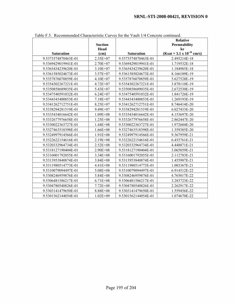
SRNL-STI-2008-00421, REVISION 0
Page 195 of 204
Table F.5. Recommended Characteristic Curves for the Vault 1/4 Concrete continued.
Saturation
Suction Head (cm) Saturation
Relative Permeability
kr (Ksat = 3.1 x 10⁻¹⁰ cm/s)
9.5373574870463E-01 2.35E+07 9.5373574870463E-01 2.495214E-18 9.5369429019941E-01 2.70E+07 9.5369429019941E-01 1.719532E-18 9.5365434239620E-01 3.10E+07 9.5365434239620E-01 1.184985E-18 9.5361585024673E-01 3.57E+07 9.5361585024673E-01 8.166109E-19 9.5357876070859E-01 4.10E+07 9.5357876070859E-01 5.627528E-19 9.5354302267221E-01 4.72E+07 9.5354302267221E-01 3.878110E-19 9.5350858689035E-01 5.43E+07 9.5350858689035E-01 2.672530E-19 9.5347540591032E-01 6.24E+07 9.5347540591032E-01 1.841726E-19 9.5344343400853E-01 7.18E+07 9.5344343400853E-01 1.269193E-19 9.5341262712751E-01 8.25E+07 9.5341262712751E-01 8.746414E-20 9.5338294281519E-01 9.49E+07 9.5338294281519E-01 6.027433E-20 9.5335434016642E-01 1.09E+08 9.5335434016642E-01 4.153697E-20 9.5332677976658E-01 1.25E+08 9.5332677976658E-01 2.862447E-20 9.5330022363727E-01 1.44E+08 9.5330022363727E-01 1.972604E-20 9.5327463518398E-01 1.66E+08 9.5327463518398E-01 1.359385E-20 9.5324997914566E-01 1.91E+08 9.5324997914566E-01 9.367959E-21 9.5322622154616E-01 2.19E+08 9.5322622154616E-01 6.455761E-21 9.5320332964734E-01 2.52E+08 9.5320332964734E-01 4.448871E-21 9.5318127190404E-01 2.90E+08 9.5318127190404E-01 3.065859E-21 9.5316001792055E-01 3.34E+08 9.5316001792055E-01 2.112783E-21 9.5313953840874E-01 3.84E+08 9.5313953840874E-01 1.455987E-21 9.5311980514773E-01 4.41E+08 9.5311980514773E-01 1.003367E-21 9.5310079094497E-01 5.08E+08 9.5310079094497E-01 6.914512E-22 9.5308246959876E-01 5.84E+08 9.5308246959876E-01 4.765017E-22 9.5306481586217E-01 6.71E+08 9.5306481586217E-01 3.283723E-22 9.5304780540826E-01 7.72E+08 9.5304780540826E-01 2.262917E-22 9.5303141479650E-01 8.88E+08 9.5303141479650E-01 1.559456E-22 9.5301562144054E-01 1.02E+09 9.5301562144054E-01 1.074670E-22

SRNL-STI-2008-00421, REVISION 0
Page 196 of 204
Table F.6. Recommended Characteristic Curves for Vault 2 Mix 1 Concrete.
Saturation
Suction Head (cm) Saturation
Relative Permeability
kr (Ksat = 1.1 x 10⁻¹⁰ cm/s)
1.0000000000000E+00 0.00E+00 1.0000000000000E+00 1.000000E+00 9.9999997794816E-01 5.00E-02 9.9999997794816E-01 9.902710E-01 9.9999993064469E-01 1.00E-01 9.9999993064469E-01 9.847216E-01 9.9999978187144E-01 2.00E-01 9.9999978187144E-01 9.760256E-01 9.9999900794401E-01 5.00E-01 9.9999900794401E-01 9.565945E-01 9.9999688017126E-01 1.00E+00 9.9999688017126E-01 9.321615E-01 9.9999019071969E-01 2.00E+00 9.9999019071969E-01 8.943561E-01 9.9995545449709E-01 5.00E+00 9.9995545449709E-01 8.120898E-01 9.9986049204570E-01 1.00E+01 9.9986049204570E-01 7.133400E-01 9.9956697754547E-01 2.00E+01 9.9956697754547E-01 5.723132E-01 9.9815482322008E-01 5.00E+01 9.9815482322008E-01 3.246634E-01 9.9503286740494E-01 1.00E+02 9.9503286740494E-01 1.416418E-01 9.8903731339770E-01 2.00E+02 9.8903731339770E-01 3.586834E-02 9.7896836554982E-01 5.00E+02 9.7896836554982E-01 2.572257E-03 9.7268858661215E-01 1.00E+03 9.7268858661215E-01 2.460128E-04 9.7165837511642E-01 1.15E+03 9.7165837511642E-01 1.506568E-04 9.7070516687436E-01 1.32E+03 9.7070516687436E-01 9.194319E-05 9.6982559165950E-01 1.52E+03 9.6982559165950E-01 5.595516E-05 9.6901573228587E-01 1.75E+03 9.6901573228587E-01 3.397722E-05 9.6827137113171E-01 2.01E+03 9.6827137113171E-01 2.059469E-05 9.6758817348953E-01 2.31E+03 9.6758817348953E-01 1.246518E-05 9.6696181961962E-01 2.66E+03 9.6696181961962E-01 7.536038E-06 9.6638809653065E-01 3.06E+03 9.6638809653065E-01 4.551868E-06 9.6586295898000E-01 3.52E+03 9.6586295898000E-01 2.747383E-06 9.6538256748168E-01 4.05E+03 9.6538256748168E-01 1.657281E-06 9.6494330949589E-01 4.65E+03 9.6494330949589E-01 9.992451E-07 9.6454180857294E-01 5.35E+03 9.6454180857294E-01 6.022658E-07 9.6417492506746E-01 6.15E+03 9.6417492506746E-01 3.628919E-07 9.6383975111787E-01 7.08E+03 9.6383975111787E-01 2.186076E-07 9.6353360187074E-01 8.14E+03 9.6353360187074E-01 1.316658E-07 9.6325400438441E-01 9.36E+03 9.6325400438441E-01 7.928977E-08 9.6299868523621E-01 1.08E+04 9.6299868523621E-01 4.774310E-08 9.6276555755424E-01 1.24E+04 9.6276555755424E-01 2.874510E-08 9.6255270797064E-01 1.42E+04 9.6255270797064E-01 1.730554E-08 9.6235838383124E-01 1.64E+04 9.6235838383124E-01 1.041792E-08 9.6218098087891E-01 1.88E+04 9.6218098087891E-01 6.271293E-09 9.6201903154447E-01 2.16E+04 9.6201903154447E-01 3.775000E-09 9.6187119391974E-01 2.49E+04 9.6187119391974E-01 2.272292E-09 9.6173624144611E-01 2.86E+04 9.6173624144611E-01 1.367733E-09 9.6161305332376E-01 3.29E+04 9.6161305332376E-01 8.232476E-10 9.6150060562771E-01 3.79E+04 9.6150060562771E-01 4.955110E-10 9.6139796310488E-01 4.35E+04 9.6139796310488E-01 2.982435E-10 9.6130427161830E-01 5.01E+04 9.6130427161830E-01 1.795084E-10

SRNL-STI-2008-00421, REVISION 0
Page 197 of 204
Table F.6. Recommended Characteristic Curves for Vault 2 Mix 1 Concrete (continued).
Saturation
Suction Head (cm) Saturation
Relative Permeability
kr (Ksat = 1.1 x 10⁻¹⁰ cm/s)
9.6121875120111E-01 5.76E+04 9.6121875120111E-01 1.080427E-10 9.6114068968056E-01 6.62E+04 9.6114068968056E-01 6.502847E-11 9.6106943683224E-01 7.61E+04 9.6106943683224E-01 3.913899E-11 9.6100439902545E-01 8.76E+04 9.6100439902545E-01 2.355668E-11 9.6094503432203E-01 1.01E+05 9.6094503432203E-01 1.417808E-11 9.6089084799285E-01 1.16E+05 9.6089084799285E-01 8.533351E-12 9.6084138841825E-01 1.33E+05 9.6084138841825E-01 5.135953E-12 9.6079624334096E-01 1.53E+05 9.6079624334096E-01 3.091163E-12 9.6075503644206E-01 1.76E+05 9.6075503644206E-01 1.860468E-12 9.6071742421306E-01 2.03E+05 9.6071742421306E-01 1.119753E-12 9.6068309309869E-01 2.33E+05 9.6068309309869E-01 6.739408E-13 9.6065175688768E-01 2.68E+05 9.6065175688768E-01 4.056216E-13 9.6062315433003E-01 3.08E+05 9.6062315433003E-01 2.441295E-13 9.6059704696144E-01 3.54E+05 9.6059704696144E-01 1.469330E-13 9.6057321711693E-01 4.07E+05 9.6057321711693E-01 8.843378E-14 9.6055146611741E-01 4.68E+05 9.6055146611741E-01 5.322516E-14 9.6053161261417E-01 5.39E+05 9.6053161261417E-01 3.203433E-14 9.6051349107752E-01 6.20E+05 9.6051349107752E-01 1.928032E-14 9.6049695041718E-01 7.13E+05 9.6049695041718E-01 1.160414E-14 9.6048185272292E-01 8.19E+05 9.6048185272292E-01 6.984116E-15 9.6046807211493E-01 9.42E+05 9.6046807211493E-01 4.203490E-15 9.6045549369452E-01 1.08E+06 9.6045549369452E-01 2.529930E-15 9.6044401258620E-01 1.25E+06 9.6044401258620E-01 1.522674E-15 9.6043353306339E-01 1.43E+06 9.6043353306339E-01 9.164429E-16 9.6042396775035E-01 1.65E+06 9.6042396775035E-01 5.515741E-16 9.6041523689368E-01 1.90E+06 9.6041523689368E-01 3.319727E-16 9.6040726769743E-01 2.18E+06 9.6040726769743E-01 1.998024E-16 9.6039999371616E-01 2.51E+06 9.6039999371616E-01 1.202539E-16 9.6039335430092E-01 2.88E+06 9.6039335430092E-01 7.237650E-17 9.6038729409363E-01 3.31E+06 9.6038729409363E-01 4.356082E-17 9.6038176256551E-01 3.81E+06 9.6038176256551E-01 2.621769E-17 9.6037671359578E-01 4.38E+06 9.6037671359578E-01 1.577949E-17 9.6037210508711E-01 5.04E+06 9.6037210508711E-01 9.497105E-18 9.6036789861468E-01 5.80E+06 9.6036789861468E-01 5.715966E-18 9.6036405910571E-01 6.67E+06 9.6036405910571E-01 3.440235E-18 9.6036055454714E-01 7.67E+06 9.6036055454714E-01 2.070554E-18 9.6035735571862E-01 8.82E+06 9.6035735571862E-01 1.246192E-18 9.6035443594893E-01 1.01E+07 9.6035443594893E-01 7.500380E-19 9.6035177089360E-01 1.17E+07 9.6035177089360E-01 4.514209E-19 9.6034933833190E-01 1.34E+07 9.6034933833190E-01 2.716940E-19 9.6034711798158E-01 1.54E+07 9.6034711798158E-01 1.635229E-19 9.6034509132980E-01 1.77E+07 9.6034509132980E-01 9.841854E-20 9.6034324147872E-01 2.04E+07 9.6034324147872E-01 5.923458E-20

SRNL-STI-2008-00421, REVISION 0
Page 198 of 204
Table F.6. Recommended Characteristic Curves for Vault 2 Mix 1 Concrete (continued).
Saturation
Suction Head (cm) Saturation
Relative Permeability
kr (Ksat = 1.1 x 10⁻¹⁰ cm/s)
9.6034155300462E-01 2.35E+07 9.6034155300462E-01 3.565116E-20 9.6034001182933E-01 2.70E+07 9.6034001182933E-01 2.145716E-20 9.6033860510282E-01 3.10E+07 9.6033860510282E-01 1.291429E-20 9.6033732109608E-01 3.57E+07 9.6033732109608E-01 7.772646E-21 9.6033614910329E-01 4.10E+07 9.6033614910329E-01 4.678076E-21 9.6033507935261E-01 4.72E+07 9.6033507935261E-01 2.815567E-21 9.6033410292466E-01 5.43E+07 9.6033410292466E-01 1.694588E-21 9.6033321167815E-01 6.24E+07 9.6033321167815E-01 1.019912E-21 9.6033239818206E-01 7.18E+07 9.6033239818206E-01 6.138484E-22 9.6033165565359E-01 8.25E+07 9.6033165565359E-01 3.694531E-22 9.6033097790170E-01 9.49E+07 9.6033097790170E-01 2.223606E-22 9.6033035927541E-01 1.09E+08 9.6033035927541E-01 1.338309E-22 9.6032979461673E-01 1.25E+08 9.6032979461673E-01 8.054789E-23 9.6032927921765E-01 1.44E+08 9.6032927921765E-01 4.847900E-23 9.6032880878086E-01 1.66E+08 9.6032880878086E-01 2.917775E-23 9.6032837938396E-01 1.91E+08 9.6032837938396E-01 1.756106E-23 9.6032798744671E-01 2.19E+08 9.6032798744671E-01 1.056931E-23 9.6032762970122E-01 2.52E+08 9.6032762970122E-01 6.361289E-24 9.6032730316466E-01 2.90E+08 9.6032730316466E-01 3.828655E-24 9.6032700511444E-01 3.34E+08 9.6032700511444E-01 2.304326E-24 9.6032673306548E-01 3.84E+08 9.6032673306548E-01 1.386885E-24 9.6032648474948E-01 4.41E+08 9.6032648474948E-01 8.347126E-25 9.6032625809602E-01 5.08E+08 9.6032625809602E-01 5.023939E-25 9.6032605121533E-01 5.84E+08 9.6032605121533E-01 3.023706E-25 9.6032586238245E-01 6.71E+08 9.6032586238245E-01 1.819837E-25 9.6032569002294E-01 7.72E+08 9.6032569002294E-01 1.095299E-25 9.6032553269970E-01 8.88E+08 9.6032553269970E-01 6.592439E-26 9.6032538910100E-01 1.02E+09 9.6032538910100E-01 3.967600E-26

SRNL-STI-2008-00421, REVISION 0
Page 199 of 204
Table F.7. Recommended Characteristic Curves for Vault 2 Mix 2 Concrete.
Saturation
Suction Head (cm) Saturation
Relative Permeability
kr (Ksat = 9.3 x 10⁻¹¹ cm/s)
1.0000000000000E+00 0.00E+00 1.0000000000000E+00 1.000000E+00 9.9998800333577E-01 5.00E-02 9.9998800333577E-01 5.487652E-01 9.9997163686602E-01 1.00E-01 9.9997163686602E-01 4.807670E-01 9.9993301618303E-01 2.00E-01 9.9993301618303E-01 4.062577E-01 9.9979231640985E-01 5.00E-01 9.9979231640985E-01 3.002156E-01 9.9951532386600E-01 1.00E+00 9.9951532386600E-01 2.182504E-01 9.9888886201051E-01 2.00E+00 9.9888886201051E-01 1.409355E-01 9.9687748591834E-01 5.00E+00 9.9687748591834E-01 5.983137E-02 9.9379000673926E-01 1.00E+01 9.9379000673926E-01 2.330090E-02 9.8908372090643E-01 2.00E+01 9.8908372090643E-01 6.789228E-03 9.8128822875291E-01 5.00E+01 9.8128822875291E-01 9.207321E-04 9.7528138507094E-01 1.00E+02 9.7528138507094E-01 1.715413E-04 9.6977996900517E-01 2.00E+02 9.6977996900517E-01 2.981385E-05 9.6355647642560E-01 5.00E+02 9.6355647642560E-01 2.817478E-06 9.5962619706564E-01 1.00E+03 9.5962619706564E-01 4.663813E-07 9.5890799984945E-01 1.15E+03 9.5890799984945E-01 3.242999E-07 9.5821318832782E-01 1.32E+03 9.5821318832782E-01 2.254696E-07 9.5754108600444E-01 1.52E+03 9.5754108600444E-01 1.567381E-07 9.5689101982150E-01 1.75E+03 9.5689101982150E-01 1.089470E-07 9.5626232356661E-01 2.01E+03 9.5626232356661E-01 7.572121E-08 9.5565434052514E-01 2.31E+03 9.5565434052514E-01 5.262443E-08 9.5506642551724E-01 2.66E+03 9.5506642551724E-01 3.657042E-08 9.5449794643470E-01 3.06E+03 9.5449794643470E-01 2.541263E-08 9.5394828537268E-01 3.52E+03 9.5394828537268E-01 1.765835E-08 9.5341683943403E-01 4.05E+03 9.5341683943403E-01 1.226971E-08 9.5290302127021E-01 4.65E+03 9.5290302127021E-01 8.525205E-09 9.5240625941102E-01 5.35E+03 9.5240625941102E-01 5.923303E-09 9.5192599842567E-01 6.15E+03 9.5192599842567E-01 4.115413E-09 9.5146169895008E-01 7.08E+03 9.5146169895008E-01 2.859268E-09 9.5101283760855E-01 8.14E+03 9.5101283760855E-01 1.986504E-09 9.5057890685277E-01 9.36E+03 9.5057890685277E-01 1.380124E-09 9.5015941473677E-01 1.08E+04 9.5015941473677E-01 9.588315E-10 9.4975388464293E-01 1.24E+04 9.4975388464293E-01 6.661351E-10 9.4936185497104E-01 1.42E+04 9.4936185497104E-01 4.627846E-10 9.4898287880042E-01 1.64E+04 9.4898287880042E-01 3.215086E-10 9.4861652353287E-01 1.88E+04 9.4861652353287E-01 2.233593E-10 9.4826237052273E-01 2.16E+04 9.4826237052273E-01 1.551720E-10 9.4792001469919E-01 2.49E+04 9.4792001469919E-01 1.078005E-10 9.4758906418484E-01 2.86E+04 9.4758906418484E-01 7.489056E-11 9.4726913991365E-01 3.29E+04 9.4726913991365E-01 5.202740E-11 9.4695987525081E-01 3.79E+04 9.4695987525081E-01 3.614399E-11 9.4666091561655E-01 4.35E+04 9.4666091561655E-01 2.510957E-11 9.4637191811530E-01 5.01E+04 9.4637191811530E-01 1.744382E-11

SRNL-STI-2008-00421, REVISION 0
Page 200 of 204
Table F.7. Recommended Characteristic Curves for Vault 2 Mix 2 Concrete continued.
Saturation
Suction Head (cm) Saturation
Relative Permeability
kr (Ksat = 9.3 x 10⁻¹¹ cm/s)
9.4609255117138E-01 5.76E+04 9.4609255117138E-01 1.211835E-11 9.4582249417221E-01 6.62E+04 9.4582249417221E-01 8.418695E-12 9.4556143711947E-01 7.61E+04 9.4556143711947E-01 5.848516E-12 9.4530908028889E-01 8.76E+04 9.4530908028889E-01 4.062994E-12 9.4506513389869E-01 1.01E+05 9.4506513389869E-01 2.822581E-12 9.4482931778722E-01 1.16E+05 9.4482931778722E-01 1.960859E-12 9.4460136109945E-01 1.33E+05 9.4460136109945E-01 1.362217E-12 9.4438100198274E-01 1.53E+05 9.4438100198274E-01 9.463370E-13 9.4416798729153E-01 1.76E+05 9.4416798729153E-01 6.574236E-13 9.4396207230101E-01 2.03E+05 9.4396207230101E-01 4.567143E-13 9.4376302042965E-01 2.33E+05 9.4376302042965E-01 3.172808E-13 9.4357060297027E-01 2.68E+05 9.4357060297027E-01 2.204159E-13 9.4338459882974E-01 3.08E+05 9.4338459882974E-01 1.531236E-13 9.4320479427685E-01 3.54E+05 9.4320479427685E-01 1.063754E-13 9.4303098269832E-01 4.07E+05 9.4303098269832E-01 7.389924E-14 9.4286296436265E-01 4.68E+05 9.4286296436265E-01 5.133799E-14 9.4270054619169E-01 5.39E+05 9.4270054619169E-01 3.566463E-14 9.4254354153959E-01 6.20E+05 9.4254354153959E-01 2.477631E-14 9.4239176997900E-01 7.13E+05 9.4239176997900E-01 1.721216E-14 9.4224505709432E-01 8.19E+05 9.4224505709432E-01 1.195733E-14 9.4210323428167E-01 9.42E+05 9.4210323428167E-01 8.306784E-15 9.4196613855556E-01 1.08E+06 9.4196613855556E-01 5.770742E-15 9.4183361236182E-01 1.25E+06 9.4183361236182E-01 4.008948E-15 9.4170550339684E-01 1.43E+06 9.4170550339684E-01 2.785025E-15 9.4158166443270E-01 1.65E+06 9.4158166443270E-01 1.934763E-15 9.4146195314814E-01 1.90E+06 9.4146195314814E-01 1.344084E-15 9.4134623196513E-01 2.18E+06 9.4134623196513E-01 9.337385E-16 9.4123436789087E-01 2.51E+06 9.4123436789087E-01 6.486702E-16 9.4112623236505E-01 2.88E+06 9.4112623236505E-01 4.506326E-16 9.4102170111211E-01 3.31E+06 9.4102170111211E-01 3.130555E-16 9.4092065399857E-01 3.81E+06 9.4092065399857E-01 2.174803E-16 9.4082297489491E-01 4.38E+06 9.4082297489491E-01 1.510841E-16 9.4072855154223E-01 5.04E+06 9.4072855154223E-01 1.049584E-16 9.4063727542321E-01 5.80E+06 9.4063727542321E-01 7.291486E-17 9.4054904163744E-01 6.67E+06 9.4054904163744E-01 5.065411E-17 9.4046374878088E-01 7.67E+06 9.4046374878088E-01 3.518952E-17 9.4038129882936E-01 8.82E+06 9.4038129882936E-01 2.444624E-17 9.4030159702589E-01 1.01E+07 9.4030159702589E-01 1.698286E-17 9.4022455177180E-01 1.17E+07 9.4022455177180E-01 1.179803E-17 9.4015007452147E-01 1.34E+07 9.4015007452147E-01 8.196116E-18 9.4007807968060E-01 1.54E+07 9.4007807968060E-01 5.693859E-18 9.4000848450779E-01 1.77E+07 9.4000848450779E-01 3.955537E-18 9.3994120901951E-01 2.04E+07 9.3994120901951E-01 2.747920E-18

SRNL-STI-2008-00421, REVISION 0
Page 201 of 204
Table F.7. Recommended Characteristic Curves for Vault 2 Mix 2 Concrete continued.
Saturation
Suction Head (cm) Saturation
Relative Permeability
kr (Ksat = 9.3 x 10⁻¹¹ cm/s)
9.3987617589814E-01 2.35E+07 9.3987617589814E-01 1.908986E-18 9.3981331040313E-01 2.70E+07 9.3981331040313E-01 1.326177E-18 9.3975254028513E-01 3.10E+07 9.3975254028513E-01 9.212979E-19 9.3969379570291E-01 3.57E+07 9.3969379570291E-01 6.400277E-19 9.3963700914312E-01 4.10E+07 9.3963700914312E-01 4.446287E-19 9.3958211534271E-01 4.72E+07 9.3958211534271E-01 3.088845E-19 9.3952905121392E-01 5.43E+07 9.3952905121392E-01 2.145827E-19 9.3947775577177E-01 6.24E+07 9.3947775577177E-01 1.490711E-19 9.3942817006395E-01 7.18E+07 9.3942817006395E-01 1.035600E-19 9.3938023710313E-01 8.25E+07 9.3938023710313E-01 7.194338E-20 9.3933390180141E-01 9.49E+07 9.3933390180141E-01 4.997921E-20 9.3928911090704E-01 1.09E+08 9.3928911090704E-01 3.472066E-20 9.3924581294319E-01 1.25E+08 9.3924581294319E-01 2.412053E-20 9.3920395814883E-01 1.44E+08 9.3920395814883E-01 1.675658E-20 9.3916349842152E-01 1.66E+08 9.3916349842152E-01 1.164084E-20 9.3912438726210E-01 1.91E+08 9.3912438726210E-01 8.086915E-21 9.3908657972131E-01 2.19E+08 9.3908657972131E-01 5.617995E-21 9.3905003234809E-01 2.52E+08 9.3905003234809E-01 3.902834E-21 9.3901470313964E-01 2.90E+08 9.3901470313964E-01 2.711306E-21 9.3898055149317E-01 3.34E+08 9.3898055149317E-01 1.883552E-21 9.3894753815923E-01 3.84E+08 9.3894753815923E-01 1.308508E-21 9.3891562519659E-01 4.41E+08 9.3891562519659E-01 9.090225E-22 9.3888477592864E-01 5.08E+08 9.3888477592864E-01 6.315004E-22 9.3885495490126E-01 5.84E+08 9.3885495490126E-01 4.387043E-22 9.3882612784203E-01 6.71E+08 9.3882612784203E-01 3.047686E-22 9.3879826162089E-01 7.72E+08 9.3879826162089E-01 2.117235E-22 9.3877132421204E-01 8.88E+08 9.3877132421204E-01 1.470851E-22 9.3874528465711E-01 1.02E+09 9.3874528465711E-01 1.021800E-22

SRNL-STI-2008-00421, REVISION 0
Page 202 of 204
APPENDIX G. DESIGN CHECK DOCUMENTATION

SRNL-STI-2008-00421, REVISION 0
Page 203 of 204

SRNL-STI-2008-00421, REVISION 0
Page 204 of 204
Distribution T. C. Robinson, Jr., 766-H J. L. Newman, 766-H J. J. Mayer, 773-42A R. S. Aylward, 773-42A D. A. Crowley, 773-43A B. T. Butcher, 773-43A J. R. Harbour, 999-W J. C. Griffin, 773-A K. L. Dixon, 773-42A M. A. Phifer, 773-42A W. E. Jones, 773-42A E. L. Wilhite, 773-43A C. A. Langton, 773-43A C. L. Crawford, 773-42A H. H. Burns, 999-W E&CPT Files 773-43A, Rm. 213


![Saltstone Disposal Facility Vault 4 Video Inspection Summary · saltstone and the vault walls,” and that “the saltstone is fractured”. [SRR-CWDA-2011-00018] On March 10, 2011](https://static.fdocuments.us/doc/165x107/5f504c3b3cd5e574d1522c56/saltstone-disposal-facility-vault-4-video-inspection-summary-saltstone-and-the-vault.jpg)