HYDRA-MATIC DRIVE -...
28
14-1 HYDRA-MATIC DRIVE TABLE OF CONTENTS Note Page No. No. Note Name Note Page No. No. Hydra-Matic Diaguosis Shop and Road Tests for Slippage Air Check Oil Circuits Adding and Changing Fluid Checking Fluid Level Replace Fluid Manual Control Linkage Adjustment Throttle Control Linkage Adjustment Internal Band Adjustments Front Band Rear Band Towing Instructions Checking Pump Pressure Driving Range Check Reverse Pressure Check Seals Against Leakage Correction of Leaks -- At Fluid Coupling At Rear Bearing Retainer Removal of Hydra-Matic Trans mission from Car Disassembly of Transmission Removal of Torus Members from Transmission Removal of Valve Body Assembly Removal of Parking Brake Assembly Removal of Front and Rear Servos Removal of Rear Oil Pump and Governor Checking Mainshaft End Play Removal of Pressure Regulator Assembly Removal of Front Oil Pump and Front Drive Gear Assemblies Removal of Extension Housing and Reverse Unit Removal of Front and Rear Units from Transmission Case Removal of Front and Rear Units from Planet Carrier Disassembly of Individual Units Disassembly of Front Unit Disassembly of Rear Unit Disassembly of Reverse Assembly Cleaning and Inspection of Parts Inspection of Case, Oil Delivery Sleeve, and Front and Rear Bands Inspection of Front Unit Inspection of Rear Unit Inspection of Reverse Assembly 2 14-7 2a 14-7 Installation of Front and Rear Units 2b 14-7 and Rear Bearing Retainer in Case. Checking Main Shaft End Play 3 14-7 Disassembly, Inspection and Assembly 4 14-8 of Pressure Regulator Assembly Disassembly, Inspection and Assembly 5 14-10 of Front Pump and Front Drive Gear Installation of Front Pump and Front Drive Gear Disassembly. Inspection and Assembly of Governor and Rear Pump Assembly 20 14-33 Installation of Governor and Rear Pump Assembly Disassembly, Inspection and Assembly of Front Servo 10 14-12 Disassembly, Inspection and Assembly 11 14-13 of Rear Servo Installation of Front and Rear Servo ha 14-13 Internal Band Adjustment lib 14-14 Disassembly, Inspection and Assembly tic 14-15 of Valve Body lid 14-15 Disassembly, Inspection and Assembly of Parking Brake Bracket lie 14-16 Installation of Valve Body and Park hf 14-17 ing Brake Assembly Checking Governor to Sleeve Jig 14-17 Clearance Installation of Pressure Regulator ilhl4-18 Assembly Ill 14-18 Installation of Side Cover and Outer Shift Lever llj 14-19 Installation of Transmission Oil Screen and Pan Ilk 14-19 Inspection of Torus Cover Inspection of Flywheel 12 14-20 Installation of Rear Flywheel Housing 12a 14-20 and Torus Members 12b 14-20 Installation of Transmission in Car 12c 14-21 Removal and Disassembly of Manual Controls 13 14-23 Assembly and Installation of Manual Controls ISa 14-23 Installation of Gear Shift Lever 13b 14-24 Special Tools 13c 14-24 Specifications 13d 14-25 Torque Tightness Note Name 1 14-3 Ia 14-3 lb 14-4 Assembly of Individual Units Assembly of Front Unit Assembly of Rear Unit Assembly of Reverse Unit 14 14-26 14a 14-26 14b 14-27 14c 14-28 15 14-30 16 14-30 17 14-31 18 14-31 19 14-33 5a 14-10 Sb 14-10 6 14-11 7 14-11 7a 14-11 7b 14-11 8 14-11 9 14-11 9a 14-11 9h 14-12 21 14-34 22 14-35 23 14-37 24 14-39 25 14-40 26 14-40 27 14-46 28 14-48 29 14-48 30 14-48 31 14-49 32 14-49 33 14-49 34 14-50 35 14-50 36 14-50 37 14-51 38 14-52 39 14-52 14-53 14-54 14-54
-
Upload
nguyenlien -
Category
Documents
-
view
217 -
download
2
Transcript of HYDRA-MATIC DRIVE -...

14-1
HYDRA-MATIC DRIVE
TABLE OF CONTENTS
Note PageNo. No. Note Name
Note PageNo. No.
Hydra-Matic DiaguosisShopand RoadTestsfor SlippageAir Check Oil Circuits
Adding and Changing FluidChecking Fluid LevelReplaceFluid
Manual Control Linkage AdjustmentThrottle Control Linkage Adjustment
Internal Band AdjustmentsFront BandRear Band
Towing InstructionsChecking Pump Pressure
Driving Range CheckReversePressureCheck
SealsAgainstLeakageCorrection of Leaks --
At Fluid CouplingAt Rear Bearing Retainer
Removal of Hydra-Matic Transmission fromCar
Disassemblyof TransmissionRemoval of Torus MembersfromTransmissionRemoval of Valve Body AssemblyRemoval of Parking Brake AssemblyRemoval of Front andRear ServosRemoval of Rear Oil Pump and
GovernorCheckingMainshaft End PlayRemoval of PressureRegulator
AssemblyRemovalof Front Oil Pumpand
Front Drive Gear AssembliesRemoval of ExtensionHousing
andReverseUnitRemoval of Front andRear Units
from TransmissionCaseRemoval of Front and Rear Units
from Planet Carrier
Disassemblyof Individual UnitsDisassemblyof Front UnitDisassemblyof Rear UnitDisassemblyof ReverseAssembly
Cleaning and Inspectionof PartsInspectionof Case,Oil Delivery
Sleeve,and Front and Rear BandsInspectionof Front Unit
Inspectionof Rear UnitInspectionof ReverseAssembly
2 14-72a 14-7 Installation of Front and Rear Units2b 14-7 andRear Bearing Retainer in Case.
CheckingMain ShaftEnd Play3 14-7 Disassembly,Inspection and Assembly4 14-8 of PressureRegulatorAssembly
Disassembly,Inspection and Assembly5 14-10 of Front Pump and Front Drive
GearInstallation of Front Pump and
Front Drive GearDisassembly.Inspection and Assembly
of Governor and Rear PumpAssembly 20 14-33
Installation of Governor andRearPump Assembly
Disassembly,Inspection and Assemblyof Front Servo
10 14-12 Disassembly,Inspection and Assembly11 14-13 of Rear Servo
Installation of Front and Rear Servoha 14-13 Internal Band Adjustmentlib 14-14 Disassembly,Inspection and Assemblytic 14-15 of Valve Bodylid 14-15 Disassembly,Inspection and Assembly
of Parking Brake Bracketlie 14-16 Installation of Valve Body and Parkhf 14-17 ing Brake Assembly
Checking Governor to SleeveJig 14-17 Clearance
Installation of PressureRegulatorilhl4-18 Assembly
Ill 14-18 Installation of Side Cover andOuterShift Lever
llj 14-19 Installation of TransmissionOilScreenand Pan
Ilk 14-19 Inspectionof Torus CoverInspectionof Flywheel
12 14-20 Installation of Rear Flywheel Housing12a14-20 andTorus Members12b 14-20 Installation of Transmissionin Car12c14-21 Removal andDisassemblyof Manual
Controls13 14-23 Assembly and Installation of Manual
ControlsISa 14-23 Installation of GearShift Lever13b 14-24 Special Tools13c 14-24 Specifications13d 14-25 Torque Tightness
Note Name
1 14-3Ia 14-3lb 14-4
Assembly of Individual UnitsAssembly of Front UnitAssembly of Rear UnitAssembly of ReverseUnit
14 14-2614a 14-2614b 14-2714c 14-28
15 14-3016 14-30
17 14-31
18 14-31
19 14-33
5a 14-10Sb 14-106 14-117 14-117a 14-117b 14-118 14-119 14-119a 14-119h 14-12
21 14-34
22 14-35
23 14-3724 14-3925 14-40
26 14-40
27 14-46
28 14-48
29 14-48
30 14-48
31 14-49
32 14-4933 14-4934 14-50
35 14-5036 14-50
37 14-51
38 14-5239 14-52
14-5314-5414-54

GOVERNOR
r
0
>-1n0
nl
FRONT PUMP
- we puRrCHECK V4Vf
REM PUMP
3-4 OVER CONTROLVALVE
Fig. 14-1 HydraMotk Transmission Oil Circuit

14-3
HYDRA-MATIC DRIVE
GENERAL DESCRIPTION
The 1954 Hydra-Matic transmissionis availableas standardequipmenton all series Cadillacs.
In operation and construction, the transmissionis essentially the sameas it hasbeenin previousmodels with only minor changes.
The over-all line pressurein the hydraulicsystem has been slightly increasedby changing theT.V. plug in the PressureRegulator Assembly.This will improve the2-3 shift smoothness.Otherchanges, assisting the 2-3 shift, include a newcompensatorvalve spring, plus changesin thedesign of thetransition andcompensatorvalves.Usingtwo front pump slide priming springs, insteadofone, will provide faster pump slide response topressurerequirements. This meansthat the flowof oil will be faster and readily available whenrequired.
A groove ha beenmachinedin the transmissioncaseto accommodatea new front pump rubber loll
ring seal in place of the paper gasket usedpreviously. This necessitatesa change in the casewhich is new for 1954.
The fluid coupling hasbeencompletely changed-- component parts aresmaller and shorter. Thecore ring of the torus members has been removed, making use of a full vane. As a result ofthis change,the mainshaftand intermediateshaftare shorter. The torus check valve retainer withattaching screws has been eliminated. The checkvalve can be installed in thedriven torus memberin a "cocked" position to simplifyeaseofassembly.
The band anchor lock nut, previously finishedon one side, is now finished on both sides. Therefore, the lock nut can be installed either way forlocking the band adjustment and will not loosen.
The transmission air breather is of the penciltype. It is locatedin a bore at the top of thecase.The intake hole for the breather is located between the transmissioncaseand flywheel housing.
The throttle shaft "0" ring seal is improved.The diameter is smaller and will improve theseal between the throttle shaft and detent lever.To allow for proper location and seating of the"0" ring, the throttle shafthasanadditional groove-
SERVICE INFORMATION
1 Hydra-Matic Diagnosis
a. Shop and Road Tests for Slippage
Check fluid level with transmission at operatingtemperatureandconnecta tachometerto enginetoindicate R.P.M.
Unit Slipping SpeedsAffected
1. Neutral Test
Increase engine speed with selectorneutral - car should not move aheadalthough there may be some tendencytonew cars.
2. First SpeedTest
Place selector leverin "Dr’ or "Lo" rangeandapply hand and foot brakes to prevent car movement, Test for slippage by openingthrottle stalltest.
CAUTION l not run stall test for longerthan 15 to 20 seconds,otherwise,the fluid in thecoupling will begin to vaporize,causingtbetorusmembers to slip. This would result in higherR.P.M. and appear as band slippage. Observestall test time very closely to avoid false readings. After stall testing car, run engine for afew minutes to dissipateheat.
If enginespeedis over 1900 R.P.M., either frontor rear band is slipping as both are applied infirst. If properly performing engine, as determined by its performancein other speeds,willonly turn up 1000 R.P.M. during this stall test, thetransmission is probably in second speed insteadof first. If engine races with selector in "Dr’ or"Lo’ ranges with brakes applied, proceed toReverse Test. An engine which turns up 1700 to1900 R.P.M. indicates no serious malfunction ofeither band.
3. ReverseTest
Placeselector lever in "Rev" with brake appliedand open throttle. If the engine turns up over1900 R.P.M. in the stall test outlined in FirstSpeedTest but doesnot indicate over 1900 R.P.M.in the Reverse test,the rear band is slipping asthis band is not applied in reverse.
Front BandRearBandFront ClutchRear ClutchReverseClutch
First, Third, ReverseFirst, SecondSecond,FourthThird, FourthReverse
lever inforciblycreepin

HYDRAA&bTlC DRIVE
If the r.arrefusex to moveforeward hut will mJin reverse, the rear hand or rear 5cr VO is inoperarive. If he car will move rward hut willno toy 05cc the diffic c. . ty Pr hr ly a the cone*r:ljtch reverse api:. rho neutral, ftrs:, and reverse tests are quick checi; of the manual contro I linkage front nd rear lmnds a tid ser edsad the reverse Unit, thai can be mLde rght u,ithe ci cip Cl:>ar
4. Secund Spceu Teat
With selector c-verili"I.o’range,s:srtoutoii theroad from a complete stnp. When the shift atminimum LhrnLt:e is noticed, Lhe tranamissiun Jain second sed The fran t :c.ulch ma" now berested for eli1 p.age by opening the throttle &depplyl 0 g the brakes To Ito d the car ata lowcnnsta,n speed. llc.3r hand and front citirel: arethe units now in op t’etio:t hut ii," staLl tee: widerE’irat Speed Test has already checked both handsfur siiaage. Any nuticeable increase in eniairespeed us jag raT I thrn t tie withnut a prupt’ r tin ndcar speed increase indicates a slipping fran:clutch,
. Third Speed Test
Using the nurmal fourti: speed ‘Dr’’ range a:30 MPH. scidce speed, ctpen the throttle wideforcing the 4-3 downshift. The shift tu third canbe felt in the car, at td,vc have positively paccdrite crajtsmiselon in lidrd speed, Decrease thecar epeed by use nf the hrak while titrot tteis maintained in the open position If the engireR.P.M. inc ret,eee, tILe rear clutch is elipp:ag. TheIroat band is also used in this speed, hutbeen checked In the First Speed Test.
6. Air Checking Oil Circuits Fig. 14-2
Drain transmission remove bottom pan, oilscreen, side cuver, and control valve assemhly.
ND Ih’ When rentaving the top ruw t,f tra asmission case side cover a:tael;iig ecrc:ss, it isnecessary remove he rear eJtgi a C Stlppot;
he frame anti the tnx;c.,l 5 ion housing so thatthe extension housing rests in i.l :c rra tiLe era as
Connect Blow Gun, Tool No J -4353-I , in aurce or air pressure approximatelY 30 pounds:,and carcr,tily check each passage in sequence, Pig.4-2. Refer to tile nil passage chart, Fig. i 4-3,
liatilig tie operetta’, uf unit actauted and presenceof any tintistiei leakage.
NCyr Ii: Reninve excess oil front tra n.s mission
me rn her
bcru, c proceeding w:th air check hy opplying*.nrcss,,re to each passage while holding a chillover rclneining passages ., ahsnrh the oi: andprotect tile OPCtS tor.
1. Vtootclu tm A.:.ply
Air presteace applied it. LI.J tine pas sage s ho u 10actuate front clutch. As pressure is iatcrnlirityl: lxapplieu. nsJsoniuni of tile clutch pisto’: should heaudible and, in most eases, can he felt by taildingfrunt drum ii rod y with free hatl e.
If an unusual amount of air is escaping sroundoil delivery sleeve area, anuther check at tiLtspoint must he made after servos are removed toobserve mars clearly the puint ‘if leakage.
ir a fog of oil is emitted fram casiderronr dt,i"., accnmpaaied by eacc,pc ofamount of air, leak is probable due tofront clutch seal
front ofgreet
a faulty
I.eakage frum any uther drilled passages in -
side of trans mis Sian case, Lii, ie p reeva re isapplied ct l’ui:t: Na. 1, is an :,,dicetictn of a faultytransmission case or oil delivery sleeve
I. Front dead Apply
Air nrc’s w.L re app is d it to this passagc ci isa 1:1actuate the front ate rv:t and apply hand wI tli : S on -
usual esespo of sir. fibserve area aruwid flat Surface of servo body, that rests on casc.No appreciahie escai uf air siiu,.luhe pre.sen: attl;:s .ocatinr.
A sottil amuant of ii leek froici jicle No. S iapcrmisaihle. However, leak from hole No. S shouldnot Lie an ape,i blow-hy, oat only an omount thatwuuicl Leak pa.st epa Ivoistor. r:ng gap
14-4
Fig, 4-2 Air Checkit0 Oil CirruiFs

HYDRA-MATIC DRIVE
Teakfrom the front servovalve body is permissible.
3. Front BandRelease
Air pressure applied into this passagewill notactuate servo becauseapply piston is held in releasedposition by retracting spring. However, nounusual escapeof air should be emitted betweenservo body and transmissioncaseor aroundbandreleasecylinder, except that which wouldnormallyleak pastreleasepiston ring gap.
4. Governor G-1 to 4-3 Valve
Air pressureapplied here should not escapebetween servobody andtransmissioncaseor from anyother passageson side of case except,possibly, avery small amount from passageNo. 2. A slightleak from the front servovalve body is permissible.When the overrun control valve is actuated, aslight click will be noticed.
5. Rear BandRelease
Air pressure applied into this passageshouldrelease the rear servo and band with no unusualescapeof air. A small amount of air will escapethrough piston ring gaps but this should not beenoughto impair normal servooperation. Observeareawhere servo body rests on case.‘There shouldbe no appreciable amount of air escapeat this
point. Check other passageson side of caseforinterconnection. While a very small amount of airmay be emitted from passageNo. 7, there shouldbe no blow-by from anyother passage.
6. Rear Clutch Apply
Air pressure applied into this passageshouldactuate rear clutch. As pressureis intermittentlyapplied, movement of the clutch piston should beaudible and, in most cases,can be felt by holdingrear drum firmly with free hand.
If an unusual amount of air is escapingaroundoil delivery sleeve area, another check at thispoint must be made after servos are removed toobservemore clearly, the point of leakage.
If a fog of oil is emitted from inside rear unitdrum assembly,accompaniedby escapeof a largeamount of air, leak is probably due to a faultyrear clutch seal or oil delivery sleeverear ring.
Escape of air from any other passageon side ofcase is an indication of interconnectingpassages.
7. Compensatorto Front andRear Servos
Air pressure applied into this passageshouldactuate rear servo to tighten rear band which isapplied by spring pressure,and to actuate front
14-5
Fig. 14-3 Identification of Oil Passages

NYDRA-MATIC DRIVE
servo to apply front band. No appreciable amountof air shoald e.scape from either front or rearservo, or any other passages on side of case exceptthat which may escape through piston ring gaps.
S. Main Line Pump Feed
Air pressare applied into this passage will result in a large amount of air and oh blowing outfrom front side affront drum assembly. This hlowby is enaitted from re.ar side of front pumup and ismlorLn While air pressure is applied to ti LiC pointobserve cloeely other passages en side of case for51 iglite St amnoulit of e ecap big sir or oil hLlhhleswhich would he an indication of ilitcrcoanecrodpassages.
9. Pressure Cage Hole ta Tap ‘f Case
Air pcessure applied into this passage shouldpruce no iea whatsoever if plug is scaled ittplace between haod adjusting screws.
Observe other passages far escape of air.
10. hxliausr Port for Valve Body
Air pressure applied late this iLolo aitould ho acomplete biow-hy to inside of transmission Costa.Remove blnw nozale and visaaiiy inspect this holeto he sure that Li IS cunnpleteiv open for its fulldiameter to the inside afcoee. A partial obstructionof this passage can cause 5xr shift conditions.
Il. T. V. l’ressure Line
ThLs peesage i.e the nnoduleti:ig T,V,prossure lineto the TV. plug in the pressure regvlator and neednot be checked in this diagnosis precedurc.
12 Reverse Booste.r Pressure
This passage directs oil behind the reverseheoster plug in Lime reesure regulatnr a ‘to "codnot he chocked ill tlmi.s di’agnusia procedure,
13. Reverse Cane Clutch i’istorl Apply
Air pressure applied inaL this passage shouldactuate tlt*o reverse cone clutch piston. s pressoreis intermotoLitly applied, Enuvement of the clutchpiston should he audible and, in most cases, canhe felt by hoidiog t.he revcree internal ar withfree hanc
If an onu.saai amount of aIr is heard escapingaround the cane clutch pistoit, cithc.r tile outer orinner seals ur both in the rever.so r.one assemblyare leaking. The unit should be disaeeoaibled endhoth oil sea is reptaced,
14. vernor Feed
It ta passage directs ataf ii Ii tic preestt te oti tothe governor and need no: be chocked a Lit.’s diag-nosis procedure
13. Line Exhausl
This passage exhausts main line pressure whoathe c.ngine a a med off and car is at a standstilland need not he die eke d in this d is gnasi.s procedure
16. 1-2 oh:
This paseage directs main line pressure oil tofast dump ye lye in rear servo and need not hochecked in this diagnosis procedure.
I’ . Procedure for V is ua I Al r Chock a I Ciai C ILHydraulics
a. Aasemble froni c hItch i e ton with seals andexpandcrs into frunt clutch drum end ia&tsiL ClutchPiston Acttiaior, ‘Foo No. J -4353-5, over piatan anddrama
I,. Install rro,itunit drum andpietnntool, nato front end nf nil delIveryRing Cott:p rea:sor. Tool No. J-l 337.
,with actuatorsleeve, using
c. Aseeathle rear clutch ptetan with seals andexpsmmdors into rear clutch drumli amid Install Clutchpiston Actuttor, ‘leo! No. J -4353-5, over pistonand drum.
d. losteli rear unit iruiaendpiston, with actuetortool, onto rear end ofoil delivery eocvo,using Ring
Fig, 14-4 Chec ki,,.j Clutch Hydraallci

14-7
HYOR.A-MATIC DRIVE
Compressor, Tool No. j -1.537
Position clutch drimiim and lietor assemblies,with uil dcl mvcrv sli,ct e :!tm:u trs,mammmisslot, case.Position center bearing cap over au delivery eleeve,indexing dowel in cap with hole an s:ccvo. Tap imitolac C u e ing Pi inch and ha mnner
CAUTIONt aot use acraws TO Pitt I cap intoptlsititln.
f. Install two sap attaching screws Soc tiiltcn.
g. Aepeat frumit and rear ciLItcI: apply checksotituned in ttema 1 and 6 under E’roccdim re Par AirCheck it mg [ra :15 muiesic 1. iou may now observe p Lato-u actioii and make a thorough visual check forcilItcIm line leaks. Fig. 14-4.
2 Adding arid Changing Fluid
Wilenever the Ii ydra . Ma- tie r attend es ion isdr a med and re i:-led im r fluid is added tu bring tholevel aD TO ‘‘Full’’ mark an the dipetick, ties! onlyCaddlac Hydra-MaiLs 1’ramammmisa:ot, Fluid or ciiAimiomatie -r rdtlsmniashci ‘‘ Fluid *ipe A’’ with anArmour Qualified nuanher embossed on top oi contaLler rhr,,ito Nao,c AQ-A’l’Fl ‘Otis assures theuser that the fluId itos all the properties eaeenttalfor correct operation nf the Hydra -Matic trans -
mIssion.
‘lhe fluid loyal ehoLild be checked every 26111111,11cc aioitg v-,im regular car lubrication, and the
Li md alma imid as. drained anc cc placc:d every 25.1:1:-htniles.
a. Checking Fluid Level
1. With selector ever iLl ! ileu traIl pasit ionrun engine at a speed nf lit M PH. for appruxalilataty I-I/I mioutes.
NclrE; Alwaysc:itgitle his beencoup] ing is filledreading.
2, Reduce engine speed to slow idle rca rsiareoiro1 the fast idle steo approximately 375-41:3 .FXi .eo the hood and remove tritlsnlisston dipstmcklocated at tite right rear side of engin ci, wipe itclean, and check fluid level.
3. With engine atil:. rai’.IIing, add fluid to bringlevel to oF full mark un dipstick ‘‘I," to‘‘F’’ marking LIe dipstick is unu qLiart.
CAUTION: . nut rh: ahovu ‘‘F’’ iiisrk 00dipstick as this will cause foaming w hen trans -
miiiesion oil is lie’.
check tIto oh level after therim’iniag to he sure the fluid
and thus ohtaan an accurate
I. Remvc dreillpan ttacl front torustiiroilgtl lie inspecthousing. F."ig. 14-5
Ping lionl transmission oIlcover, whict h is a coessth he
ion hole in lower flywheel
2 Miowci:d fluid Lii drain cOiilpletely and rein-stah drain plugs and inspection hoic covet.
3. Open hood anti add 7 quarts of Automatic‘i’railslliissiiao ptuid into the oil filler tube.
4. Run the ar,g:tio s.:a speed of approximately300 1P.M. fur appraximately 1-1/2 t:diiutes wirltthe seiec:or lever in ‘‘N’’ inet;trai: -
5. Reduce engine sTood, to ahaw idLe carbLirmt.uroff tee rits. Idle stiip:i n.:md acid 2-2/2 to 2nf fluid to bring Ide lc:.,:c:i ir;n to tile itt.tr.< iI:lthe dt pa. mck. -
NOTE; i3:t: capacity ortlte Hydra -Matiç trans-nmieslaa is ipbroxinlatciy lii quarts for a teCh,but the correct :c-vci is dernnined by the markon the gaas r a titer than by Li ic am’ lout It added.Fe not ov evfi I as fuamang may result :i on theoil is fret.
n Shct off engine, repiacc d:pstiek acId closehood.
3 Manual Control Linkage
Adluitment
1 Uaacotiticct tt:imtcai cc,:itro, i’od f’nm controllever at transmission I’tg 14-&
Hg. i4-i Ttaosmisicr _tol,t
b. To Replote Fluid
‘2 Movo control l..:er at tranatt:IssiLiI, to tiletiornln, drive pe.sit:t:n The drin aition can be

14-g
HYDRA-MATIC DRIVE
lap l cp’hasiaa Luika5a A 0a
Ilyd,aaaik ,els
H,dJa
--fsl al Oa,l,
Hy
C
rh u:ui: k,,d
op
ii:. a
F . t 4- Monun I od Tkot he Control Ii okog,
found by maying the manual lever at tile trans.Os SiO 0 ally forward and upward and then nlov ing
it rearward until the first deient is felt.
3. Move selector lover on steering column tohe stop in r lIar Inal ‘DR -4’’ left humid or row
position.
4. Adjust clevis on lower end ulf cootral rod tmii-til clevis pin can be inserted freely through chevisand manual control lever.
5. Assemble chevis, pin, and lever, and installnew cotter pin.
4 Throttle Control Linkage
AdlustTnent1, Rotrioe rramieiimissian throttle conmrt,h lever
rhevis pin, and check lever positian with Tool No -
3-3065-C by fitting tool to rear face of transmission case slid inserting clevie pin through Leveramid proper hale it, tool while lever is in its rear -
ward position, rig. 147, If throttle lever i-s ntis-aligned, hring it inio elignitiemit by bendiog withTool No. I’ 2020 -
3. Remove spring clip from carburetor to dashrelay rod trunluoll end remove irunnion from dashrehey lever.
4. place 1/4 inch dr:ih shait tliroitgll gaginghole iii disht relay lever and :nta dash relaybracket. See Pig. 14 -ñ shove -
e t carburetor th rtm tthe imi I ,oi idle position375 II I’M .. with transmission in drive range.
0. Adlust carburetor to dash relay rod rrmlnnionto allow free entry into dash rclsy lever.
7. hr.tu1h spring chip in truniiiou.
8. flack off both jani nats on the throttle valverad at carburetor to allow free mmivemant of rodin trunniticI.
9 P:mst: oui end of throttte valve rod to pa dial,
ransni iss ion : h ti i tthe valve againai a stop -
10. Aring rear jam nut up against trul,nioli andhack off 3 comphe te turn e
NOTE: This adjustment ‘nay be increasedor decreased tu improve shift cilaracterislica.
1. Ti g: lie Ii [remit ja ir, ii Ut. ma king certain link -
age moves freely,
12. Relilove 1/4 imicli drilland check sitiou of icedopen dirot the - Pedal s imoui :dslight prescore ‘:aihow 1/2’’beeti re l:Fay ed :- in me’. i tm t.‘-ott IC
shank from dashrehaytiter pedal with s.d detouch floor met withclea raoce if mat hasis widc open,
13. Adjust accelerator pedal position at pedalraid of c:isit relay tan actte.et-aar pads: rod.
1
Hoia
Rpl taikma
Rad
Vt
Fig. 14-7 Tbnople Lever Charring Gauge
2. Assemble linkage to transmission throttlelever and install new cotter pin.
‘4. Road teat car to insure proper s]iiftirlgcharacteristics F:g. 14-3,

14-9
HYDRA-MATIC DRIVE
3.07 AXLE, 62 AND 60S SERIES
Drive 4 Range Drive 3 Range Lo Range
Minimum Throttle Full Minimum Throttle Full Minimum Throttle FullShift Throttle At Detent Throttle Throttle At Detent Throttle Throttle At Detent Throttle
* * * * * * * * *
1-2 5-8 14-18 20-23 Same as Drive 4 Range Sameas Drive 4 Range
2-3 11-16 33-38 36-41 Sameas Drive 4 Range
3-4 21-26 68-75 7379 73-79 73-79 73-79 Shifts 2-4 at 42 MPH
4-3 14-17 27-31 70-75 70-77 72-79 72-79 Shifts 4-2 at 41 MPH
3-2 8-12 7-10 21-24 Sameas Drive 4 Range
2-1 4-7 6-9 8-11 Sameas Drive 4 Range Sameas Drive 4 Range
3.36 AXLE, 62 AND 605 SERIES
1-2 5-8 13-17 18-22 Same as Drive 4 Range Sameas Drive 4 Range
2-3 10-15 30-35 33-37 SameasDrive 4 Range
3-4 19-24 62-68 67-72 67-72 67-72 67-72 Shifts 2-4at 38
4-3 13-16 25-28 64-69 64-70 66-72 66-72 Shifts 4-2 at 37
3-2 7-11 6-9 19-22 Sameas Drive 4 Range
2-1 3-6 5-8 7-10 Sameas Drive 4 Range Sameas Drive 4 Range
3.77 AXLE, 75 SERIES
1-2 4-7 12-15 16-19 Sameas Drive 4 Range Sameas Drive 4 Range
2-3 8-13 27-31 30-34 Sameas Drive 4 Range
3-4 17-21 55-61 60-64 60-64 60-64 60-64 Shifts 2-4 at 34 MPH
4-3 12-14 22-25 57-61 57-63 58-64 58-64 Shifts 4-2 at 33 MPI-1
3-2 7-8 5-8 17-20 Sameas Drive 4 Range Sameas Drive 4 Range
2-1 3-5 5-8 7-9 SameasDrive 4 Range
4.27 AXLE, 86 SERIES
1-2 4-6 10-13 15-17 Sameas Drive 4 Range Sameas Drive 4 Range
2-3 8-12 24-28 26-32 Sameas Drive 4 Range
3-4 15-18 49-55 53-58 53-58 53-58 53-58 Shifts 2-4 at 30MPH
4-3 10-13 19-23 51-55 si-56 51-56 51-56 Shifts 4-2 at 29 MPH
3-2 6-9 5-7 15-17 Sameas Drive 4 Range
2-1 -_3-5 4-7 6 8 Sameas Drive 4 Range Snnie s Drive 4 Range
*Shift SpeedsMPH
Fig. 14-8 Hydru-Matic Shift Points

1-IYDRA-MATIC DRIVE
5 Internal Band Adjustments
No’r;;; In ormiet- to obtain rnaximui]* handIie a tid sinned tin *slii fri lie tIme II ydi’e -Me tie be mmdsinn us: Inc a dj a sred by the. mm m’m ::il Met hod at 50Umiles After the- insmida have bean adaamcd, mImeTV rttd a: the carhutetor tt.i*.IM b<.ad-:istedand WAD TESTED to insure p topc’r PS tforinnance as descrihed in Not.-, 4
1, Dramm, l]srlra-Metic fiLmid Iritmmm traosr:isaiiin -
2, Rennnve Tr ainact isaioin cii pa mi and gasket.
2, Remai’r the pmepiufi-oinn front sc-rvo, Loosen‘‘bus’’ adjustang aurea’rd Gage No, J_ftii., untila no rox i tile tel y I / S*’ of ihire ads a r exposed ‘abovegage body. Install gage, tighmLaning hr HAND ONLY.fOg, 149.
a. Front Band
3, Using a wrenchi, tighten till S ‘‘hex’’ idit:.st:itgaerew 5 turmma fro::. tee poem: "imure it was fc:mby lnatnd titer steinn jI.:S V tn.mc!tei: piston.
6, Aeinnove floor onst over hsin:l srlju.sti it*s hmilacover and remove cover.
7. Loasen band ad:umatitne screw lock nmit
adjusting aerew .mn ELLime bard odtasLtog gage
tighten hi:mrd..saeLirehy ta 4o-50 ft.
Tighten ran I bardknurled wisher an tap ofis joet free to t.i
pIe,ld *naod ai:jmme:irpdj a-at ing Sc new Inc k nLi
Iha. t,n tore -
- Lse:t i4aec tmdjLiat 1113 Sc rn’s at least sixfit hi ti isits amid remove gage. [net aLl slid tfgh tenpipe piLlg.
b, Rear BandNi V I .i-: Iiofn r a inn at is g hand adj a a tment , be
sure anchors seated oa ed,Lmatimmg ar re½ a:md m.mehand is centered tin i:rutnn
I, With rear bamie centered on drum, tm::tSiiha Ite. a’hjimaii 4! sctv.’ until at.t:ieting ii’ver clan-tac!:s face o gegc i-ide I - Fig. 14-10 -
1-I - lb
4. Ti,,’::an the ‘‘hex’’ achjustittg eetewwiln fiitgc:retintlh the s:eiti of gage is felt to inST touch pistonin frant servo.
Pea, SameCola - J .507
Fig. t4-9 A;iasfi"g Fro,,t Enod FLg. 14-10 Adunting Raar Ban:

14-11
HYDRA-MATIC DRIVE
CAUTION: Do not go beyondadjusting screw is accidentlyadjustment, loosen two or threepeat adjustment.
2. Hold band adjusting screw and tighten adjusting screw lock nut to 40-50 ft. lbs. torque.
6 Towing Instructions
Cadillac cars equippedwith Hydra-Matic Driveand driven less than 1,000 miles, should neverbetowed unless the propeller shaft is disconnected,or the rear wheels are raised off the ground. Thisis necessarybecauseof possibleclose productionlimits which might cause the front clutch to dragandpossibly burn up.
Cadillac cars equippedwith a Hydra-Matic Drive,driven more than 1,000 miles, may be towed50 to75 miles with the selector leverin the "Neutral"position, without disconnecting thepropeller shaft,or raising the rear wheels off the ground, provided the Hydra-Matic Drive was operatingsatisfactorily up until the time of towing.
Towing speeds of 15 to 25 M.P.H. should bemaintained when possible throughout the distancetraveledto insureproper lubrication.
7 Checking Pump Pressure
The pump pressure can be checked with thetransmission in the car, using a gage calibratedto at least 200 P.S.1.
1. Remove band adjusting hole cover from floorpan, clean dirt from top of caseand removeplugfrom top of transmission casebetweenband adjusting screws.
2. Screw pressure gage line fitting into hole incase, with gage placed so it can be readfrom thedriver’s seat.
3. Drive car until transmissionoil has reachednormal driving temperatureapproximately200°F.
a. Drive Range Check
The following tests may be made by road testor with car on jack stands.
1. Zero throttle pressure-At3OM.P.H.infourthgearwith zero throttle, oil line pressureshould be64 to 72 P.8.1.
2. Full throttle pressure road test -. Fullthrottle pressure in fourth gear at 30 M.P.H. fullthrottle without going through detent should beat
least 40 P.S.I. higher than zero throttle pressuretest reading. Car on jacks
3. To check the operation of the rear pumpalone, drive the car at 40 to 45 MJ’.H. in fourthspeed.Then shift to neutral andturn off the ignition. Pressureshould beat least 75 P.S.!.
Low rear pump oil pressureshould becorrectedby replacement of the pump gears, by correctingexcessive endplay in the gearsor by checkingforleakagein other units.
b. Reverse Pressure Check
1. Place the selector leverin reverse positionandnote pressurewith enginerunningat400 R.P.M.This reading should be ashigh or higher tban thepreviouspressurechecksin drive range.
2. With the selector lever in Reverse,applythe foot brake and increase engine speed to halfthrottle, Pressure could increase to 145 P.5.1.minimum. The pressurerangeat the aboveconditions is from 145 P,S.I. to 210 P.8.1.
If pressure readings arej below the specifiedamount for any of the abovetests, amalfunctioningpressure regulator or a leak in the system isindicated.
8 Seals Against Leakage
The severalpFecautionswhich must beobservedto prevent fluid leaks areas follows:
1. Use new gasketsand"0" rings wheneverthereis a disassembly.
2. Use a very small amount of vaseline orheavy grease to hold gaskets in place duringassembly or to seal gaskets.Never use gasketpasteor shellac.
3. Be sure to install washersunder thecorrectscrewswhen reinstalling the front cover.
4. Use PermatexNo. 3 on screwsto sealthreads.
5. Make sure flywheel cover gasket is notwrinkled or creasedwheninstalled.Also makesurethat gaskets have not stretched or shrunk duringstorage.
9 Correction of Leaks
a At Fluid Coupling
If the fluid level is found to be low duringperiodic lubrication inspections, check for fluid
adjustment. Ifturned beyondturns and re

14-12
HYDRA-MATIC DRIVE
leaks. Leakage may be at several points, amongwhich are:
cover, the leakage is between the torus coverneck and oil seal, or betweenthe front coverandthe case, or at the rivets that hold the dampenerto the torus cover. If none is found either on theflywheel or torus cover, the leakage may be occurring at the joint between the flywheel andtorus cover.
Leakage between the flywheel and torus covercan be corrected by installing a new gasket.Makesure that the gasket is not wrinkled and fitsproperly. Tighten the cap screws evenly to atorquetightness of 40 foot-pounds.
Leakagebetweenthe flywheel andcrankshaftcanbe corrected by using new flywheel bolts andanewgasket. Coat the gasket with Gasket CompoundSupplied by Factory PartsDepartment when installing. The ridges orraisedportionsofthegasketare installed towards therear of thecar.Torque to75 foot-pounds. Ifnew screws anda gasketdo notstop the leak, the threadedportion of the screwsshould betinned.
Leakage between the front oil seal and toruscover neck may be due either to a defective oilseal, to excessiverunout of the torus cover, pinholes or roughness at cover neck. In extremecases, it may be necessaryto replacethe cover.
b. At Rear Extension Housing1. Betweenflywheel andcrankshaft.
2. Betweenflywheel and toruscover.
3. Between torus cover neck and front oil seal.
4. Between front oil pump housingfront coverandtransmissioncase.
To determineat which point the leakageoccurs,Fig. 14-11, remove the lower flywheel housing,wash the flywheel and torus cover thoroughlywith cleaning solvent and allowto dry completely.Then spread a clean piece of paper under theflywheel and cover, and run theengine at a speedequivalent to 50-60 miles perhour. Whensprayappears on the paper, shut off the engine andcheck theflywheel and torus cover for the presenceof fluid.
NOTE: To perform the above operation itwill be necessaryto cut an old flywheel housingaway, leaving just enough of the housing toattach it to the engine and to mount the startermotor on solidly in order to start the car.
If fluid is streakedalong the front face of theflywheel, the leakage is betweenthe flywheel andcrankshaft. If fluid is streaked along the torus
Place selector leverin reverse and run engineat 1500 R.P.M. Check for leaks betweenextensionhousing and case. If leaks arenoted at this point,replacegasketbetweenhousing andcase.
Check rear oil seal for leaks and replace ifnecessaryas described in Note lb. Checkextension housing cover gasket for leaks and replaceif necessary.
10 Removal of Hydra-MaticTransmission from Car
1, Place car on jacks with all four wheelsapproximately 12 inchesabove the floor.
2. Disconnect propeller shaft at rear universaljoint flange and removeshaft with front universaland yoke.
3. Disconnectbattery andremovestarter motor.
4. Remove slush deflector from lower flywheelhousing.
5. Remove flywheel housing lower cover anddrain transmission at oil pan andtorus cover.Pig. 14-5. SeeNote 2b.
ncr Rivet
Cover
Oil Seal Ring
TransmissionFront CoverOil Sealto TorusCover Neck
I runs missionFront cover
Rear MaiBearingOil Seal
Torus Coverto Flywheel
Fig, 14-li Location of Possible Oil Leaks

14-13
HYDRA-MAIIC DRIVE
of oil pan.to oil pan,
*IbnI N0
6, Plaso a jack under engineat rearusing a wood blurb to prevent damageor use epociul Engine Supnrt Stand
- tJ 6 a
7. Remove tra,ismiaeion fluid filler tube fromtranemissonofi pan -
B, Place Hydra-Lift under car and raise tran.e-mission joe enoagli to toke strain off rear enginesupport.
9 DiaconnecE engine rear support 21 trons-mission extension housing, Renvavebr’ocke crussmen1r lhal carries .support
10 Remove throttle co:crul rod hum throttlelever ci] Iransmi.ssinn.
it. Disconnect manual shift rod from monuoiICV Cr 00 rtanamissinn r nntto I
L2. ieillove throttle control lever and ma;ioeIlever from side or :raosmissic,n case to preventdajinage from benotog.
13 DiscnnnecL speedornetc.r cable at rear ofransmission.
L4. Remove cap sr.rews holdaig torus covet iaflywheel and push cover toward rear of car todisengagedowels In2sting ir!nr. f!ywhcel
CAUTION: Cover should nuL be prred awayfrom I sheeI
15. Lower jack or Engine Support Stand,ToolNo. j -8068 underengine nil pan until top or f:ywheel hnusinzcieers fl]xr pan.
16. Remove thur screws holding fl¼’heel housing to enginecrankcase.
IV. Iteonove transmission ond flywheel housingas a *.uhi; by moving back Lowurd reer ulcer, andat the same rime Lowering assemblyto the floor.Fig. 14-32.
Ii Disassembly of Transmission
a. R,niavol of Torus Members, lortis Cover andFlywheel Housing from Transmission Flo. 14-12
NOTE: Fioid coupling Cannot beremovedasunit. rhe r.omn c! iKe III 5 he I ak en off one
at a time as describedbelow.
Place transmraaionand fluid coupling ease"bly in naturej-254L-A on bench,
2. Move shift lever on side of ,ranamiesiontoward rear to reverse posialoji.
3. Slreigliten mainshsft nut :oci washer. LteingLose! a Id 0 I igh L hammer.
4. Eertnve maioal,a& no, using I _7/i6!’ socket.
5. Slide driven tort’s m!mher off frnnt end ntransmissionmainahaftCi tia clieckvalse‘aaispring,
NOTE; If Lorri Si icki. :ap end of maittahailwith plastic or similar hammerand a t:he same
me, pull n.ti torus member.
6. Remave driven roros enap ring from mainshaft
7. Remove driving Lorus snop ring front inter-r.nednoteshaft.
8. Removedriving torus ,ocmttber.
CAUI’ION; not attempt to remove toruscover ,rid driving Lorus members together.
Ft. 14-12 Rmn’ina 1,on,.,F,tioo Fig, l4-3 Tow’ Men,beoon Trn,m.,tio.,

14-14
HYDRA-MATIC DRIVE
9. RcmlIove to r us cover. Do not a tem,ipL LII re -
move :otus cover by piilli’ig si pealthig on coverin a rough maimer as this may reauI: o 5 0 rodc:ioil seal ring. Work hub of tortLe co.-erhark’ tttroLIgitoil seals gentls. and Omen poll tonic cover forwardwith a quick jerk.
10. Remove fourSr rews and lock washershold -
ing flywheel reor ‘nnosi 1mg to fron L of ransmia5 inncnae. Remove flywheel rear Iioualng and gasket.
Move shift lever on side of transolissiojt to!l! poei,ion
i 2. I,00.sci clamp acre Phil ip.s head 110 Idingdi,rfL lever to inner throttle lever shaft at side of,runsmn:aalon amid remove lever.
13 Remove oil P0.1 cc roes I /2 and locktsaeiicrs- Removeoi pan andgasket.
14 Remove side roveracrews 7/16!i and coverwith gasket. FIg. 14-14.
NO 1L: When ret,,ovcd ci car, roar enginemoo ‘mc elm old he removed to si owl i a euse ofremoval.
15. To avoid damnge to oIl pan screen.reen and front PU! O intake pipe Os an a s-scowla
fm n Lhe froit t pomp and rear pa] np intake p PC.Fig. 14-15.
b. Removal of Valve Body Assembly
mission in car. Side cover must he rer-’nveeOil pall needant he removed
- Lsi,ig screwdriver, removepressureregula-
tot reverse oil pe from val i c hv and case.
Pig. 14-16.
CALflON: !.;e very light pressure and hecsrerai in Itrying o!Jt pipe eince it bendseasiiand might be difficult to Pu’ hock.
1.;lcoiovc oar screws 17/10’; imuidi"g valvedy to TtaIiS]msSiOIL case. Kig. 14-14.
Fig. 14-14 Trantmltsonwith Side cocK Remn.,ed
3. Work valve body toward Irtmnt of case to
N01E: Removal trot be done wit]I rand- Fig. 14-15 Rs..ttoaiog Oil Pen Srmso and I.oeke Pipe

4-15
clear governor pipes and revers clutch p:pn.Re careful not to kink pipes when sliding valvebody forward.
4. Covcrnor ?!p5S mar remain either in valvcbody or brockei aeeemblv.Removegovernor pipes,Reti Love r eve rSe clutu It oil p: Pt, from case.
S Bo .curc io protectanon as it is removed -
paperor cloth.
HYDRA-MATIC DRIVE
Removal of Purking Bruke Assembly
NOTE: Removal :rtay he done with tralis-mission in car. Side cover and valve body iibiIliost he removed.Oil pan neednot he removed.
Unhook parking breka reletse spring frostpin assembly at end of bracket and rcomovcspring.
2. Loosen lock plate and remove parkinghrakepaw] support bolt 9/ 16’’i froi,i rear of case.Fig. 14-17 - Move pawI down in to caee a tm a fromreverse i mite rila I geer. Paw ca ii ant be removedat this Dm0.
3. Loosen lock plate and remove two boltsIrlding bracket aesembivto cose.
4. Pal I governor sleeveoff, he ing caref,! I ‘lot tOtilt it because-oil rings -.souldcwistendbedamaged.Do ,:ot lose rolet for tie parking bracketcrank.Fig. 14-IS.
.5. Removepark/agpawl from case.
d. Removal af Frani and Rear Servos
NOTif: Scnrvos may he remove.c with trans -
mission in car. Side cover need mc be removed.Rear servo mna be removed without remnvingfront scrvo.
I. Reonove governor oi. dolivery pipe. Be careful mini to crush this pipe w hen prying t fro on frontservo and governor. Fig. 14-19.
2. Loosen locK nuk I34’’ and hack mrff rear handadjusting screw 3/k’ at least five turns.
Fis. I4-l RsnioaiogReverie Oil Pipe
valve body From dirt aswrap valve hndy an c’ean
Fig. 14-t RemaningPekina Fowl aoir Fig. 14-Il leonnairig Oov,nio Sleeve

14-16
HYDRA-MATIC DRIVE
NOTE: c sure this screwto take ad tension [rein thebefore loosening rear servo
Loth aervee may he removed together as anassennhiy.1 Fig - l4-21i -
5. R eninve frotit ccv a pulling straight ‘Lii fromcaseoff freer pump delivery pipe.
6 Rc move frtmn t purnip Cl cliv cry 1ipe by pui I ingSt raigilt up from front pu nip -
.. R.moval of Rent Oil Pump and Governor
NOTE: Lit its may - removed with Trans-
mission in car. Rcuiccs removal of oil pan,parking braccet Note II valve kidy Nc,tc!I Ito and rear servo No:e I1d.
Fig. 4-I? Removing Oaveronr Oil Del’,ve,y Pip
is loosenedenoughhand applt springattachimig screws.
Fig. 14-21 Removing Reo Oil Purre nodGoverna a nibly
3. Removefront tad rear servo oltaching screws9/]’..
4. Separate rear servo from front servo atcompensatortransfer pipes ha moving rear Servotoward rear of trsI,snnission OtsengageconipenSetor Pipes from servos- Retrieve rear servo -
Fig. t4-20 Ren-vin9 Sec.,em Fig. 14-22 Cueok ing Moi nho ft End Ploy

14-17
HYDRA-MATIC DRIVE
Reg,jlnln Plug2
IV Flug
RevarieBooate P!ep
Regalaror Spdng
-
Regsln!c’Valve
DampenerSpring
R;ng Seal
Fig. 14-23 Piare
1. Re:rieverearoilpumpattachingscrowsl/T’:.
2. Position governor so that the large roundgovernor 0-1 weight is n., s-ard front of trans -
mission.
3. Remove guverilor and rear pump assemblyby moving toward valvebody side t,f transnhiasioticaseand lift to clear case.Fig. 14-21.
F. Checking Moinchoft End Ploy
I , Install Mainshafi Rnd Play Coide. Tool No.-2537 -B nver nnainsltaft a r.d intermediate shaft.
Fig. £4.22.
2, Set up dial indicator ue traitsniisauin caseusing Tool Mi. 3.. 5.
3 Insert screwdriver betweenfront clutchdrumand eeoter hearing cap, I]oldLng front planet annforward - The screwdriver should ne placed at anangle to p rc-.’e-Io U a;c to the oil tleitvery Cioove.
4. 5sive ni’einshaft hack and forth. Endclears’iceshould be .004’’ to .OIS’’. He sure ttt get last freemainaliaft end play. Fore’ rig ni vi mishaft w ill give
Regolotot - tapladed
inaccuratereading.
OTE: Record amount of end clearance sorita: the proper Selectivevrasherceo beina-adedwhen the tranamieaioli is reassembled.
S - Remnve screwdriver from between frontclutch drum and center bearingcap-
Rotonve dial indicator and nnaiaahaftend playpanda
g. ReniavoI of Piessure ReulotnrNOTE-. ‘flue essemblymay be removed with
;ranem,:LssiOti incar
- Loosen reguletor valve plug 1- l/4’f -
AlTION: Prescore regulotor valve assem
bly ia coder spring pressnre.
2. Hold preastire agailis: regulaTor plug whileoiec.rcwing plug by hand.
3. Removepressure phigfrelli side of
pb.mg, reverse booster plug, T.V -
springs end valve as an asacmhlytransiniasion case. Fig. 14-24
P ross a me Ragaktor Plug Regu l&nr Spring F r mit
Cover R&ntnlng &te-s
F o 14-24 Re viog ?r.iiare Regi Ierat A,ientl
14-13
HYDRA-MATIC DRIVE
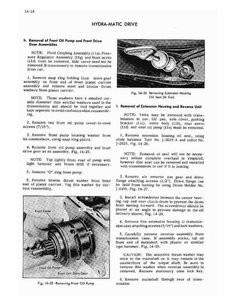
h. Removal of Front Oil Pump and F,ont DriveGear Assemblies
NOTE: Hi LJ CouIng A sseriibl l I LI, Pres’sore Itegulacor Assembly I Igi and front aervo2 idi tiiost be remoend. Side wvcr neednot beremoved Iris necussai-vto remove tran.smissiootram car
1, Remove soap ringassembly on front endaaucxithly and removewiehera from planet carrier
Hiding fruill drive gearui front planet carrier
steel and breitzv thrust
NOTB: These -.s- eahers have a amiiler outside diameter titan sitiiifa r waalicrs used ir. thetransmission and ahould he tied togsthsr andkept separateto avoidcanfuvie,l sitenreossembl-itig.
2. Remove two front oil pujup cslver-to-ca.Rescrews 7/1
3. Remove front puilip locating washer fromits ceunterlxlre, using snap rIng pliers.
4. R einove frtsn t oil pump aasenihIy a tid frontdrive gear as aLl assembly.Fig. 14-25 -
NOTE: Tap lightly treat rear of pump wi:lilight hamtiicr and brass drift if necessary.
5 Remove’’O’’ ring from pump.
6. Remove bronseend of planet carrier.reeL rea.ssemhiy.
thrust wa.sher from frontTag timla waaher for cor-
i. Renioval of Extension Housing and Reverw Unit
NOTE: !uirs may h-s removed S it]! truns-mission in car - Oil pan, side cover, porkingbracket I in, valvc body Ilhl, rcsr servoI Id and rear oil pump lie must be removed.
Re.mova extension housing nil seaI, usingslide hanliner Tool .No J -26l9 A atid coliet No -
J-2623. Nig. 14-16.
NOTL-. Removal of seal will not be necessary unless complete overhaul is required,however this aeal cd-n do removedand itratal ledwith transmfssinnin car If It iv leaking.
2. Remove six reverse son gearflange attaching screv.s I/2’’i - Dr2vebe hed froni turning by using Druonj-1459. Fig. 14-27.
3 ins ‘.ai I sr.rewdriver betweeli Time centerbear-
tog cap and rear ella ci: drum a p rC:vent the drunifrotii niovilmg ftsrward - rite acrewdi-iver aliould bepi acee/ at an angle to prevent damage to the oildelivery sleeve. Fig - 14-lb.
4. Reoinve five extension housing to transinis-
sion caseattachingscrews/i 6’’ and iock washers.
5. CereuIly remove reverse assenthl frunitransmission case. if aasenthiy sttcks* tsp oil
front end of mainehoft with plastic or aimfiar
type hammer- Fig - 14 -Zi -
C’AUl ION: The eelec:ive throat washer nay
stick to the maiashaft or it may remain in the
councerhore of the output shaft. Be sure toremove this washer when reverse as.semhlyisremoved. Remove stationary cone lock key -
6. Remove moinaimfi throtigh rear uf trana
and drivearge call
Holder Nt>,
Fig - ‘4-26 Removing Eioeo ion From itigOil Seal En Car
Pig. 14-25 Raireving Front Oil Pomp irssioli.

14-19
HYDRA-MATIC DRIVE
2 Remove two centerscrews 5/3’’l and leek plate
bearing cap case
8 Insta] I Rear Hub Retainer Tool No. J-2l 74on rear unit and remnve screwdriver from frontof rear unit. Fig. 14-20.
I. Removal of Front and Rear Units from Case
NOTE; Transmission moat be removed
-
Remove oil pan, parking broEket lie, valve bodylib, servos lId, rear nil pump lie, Fires-tIre regulator assarrrbl2’ II g , fro at Pu to aad
front drive gear I lb reverae assemblyandmain.shaft iii.
1. Using a tght hammer and chisel, bead hackedges of lock l:.ialc under two ccnrcr bearingcaptatctchimmg st’.rews-
NOTE:lance by
em
I: mayor: miecessaryto equalizedie-moving front and rear clutch drumsnt:k. wrench to cet arc rc-w head.
ina:cli suitable epri:mg em- wire :o hold frontbait,- on fi-oni unit drum.
4. l,irt hoth fratv, and rear clutch and rti:.1a seemh Iie.s, -,v:Lli bands 1mm transmission caseFig. 14.29.
5. Remove bands from front and rear unit.
k. Removal of Front and Rear Unit, fromPlanet Carrier Intermediate ShaFt
Place planet carrier with ft-oat and rear
Fig. 4,27 Removing Ru,,rin Dmive Plunge haIti
7. Remove bronze thrust washhr troth rearclutch huh
-
Mali ShalE
.__-. Soreedmiverb&m,,eem,Re-.- Clma:h cave, and Benrimg Cop
Reui unit erie
/ eveie 0 riva Fl aisma,danFlowing
/ Reese Umit Mte’ilyRan; Umhit Planet Cm,‘a,
Fig 14-21 Re n,aving Extan inn Hnudng and Roves. Uni I Aiian,b ly

14-20
MYDRA-MATIC DRIVE
clutch and druma assemblieslate huldim,g fixture,Tool No.1-2117.
2. Remove rear clutch hub rear snap ring.
3. Lift rear unit fram planet carrier,
4. Remove rear clutch hub front sn-op ringfrom planet carrier.
5, Remove center bearingcap frnm oil deliverysleeve
NOTE Be careful not La damage or losebearing Cap otherwise entire case would haveto he replaced- Discard center bearing c.aplack plate as it should nat ha used again.
6. Remove oil delivery sleeve fromintermediate shaft
Fig. 14-at Removing Fmotit Unit Clutch Pietnn
7. Remove snap ring frani recessin front unit.
CAUTION: I bid enap ring on whtle liftingfrom carrier U, avoid damagingbearimigsurface.
Lift front unit aeseaihly torn planet carrier.
9. itemave steel and bronze rhrustwashersfromrecessin front unit,
12 Disassembly of Individual Units
a. Disassembly of Front Unit
I. Place front unim aesemhlyin press and re,move clutch cnver retaining ring. Fag. i4-:l.
Z. Separate drur - b tapping front 1ace oIcearer gear en front clutch drum with plastic ersimilar hammer.
3 Remove front clutchclutch drum by bm’titpiaggear on soft wood black. Fig. 14-31.
4. Remove six inner and six outer front clutchreleasesprings from front unit drum.
5. Ram’iove four comgcsitioa clutch drive andieur steel clutch driven plates from drttms FIg,14-31.
6. RemItevo rubber piston scale and brass expanders from annular piston and clutch drumpiston. Ilse blunt edgescrewdriver.
b. Disassembly of Rea, Unit
1. Remove Rear Clutch HuhNo.1-2174, remIt rear Unit drum.
annular piston fromfrent face of center
Retainer, Tool
2. Remove rear clUtch Itoh and broazc thrust
Cltth Cover
g, 14- 2 Remos ,eg Front and Rear Unite
haM:Unit CIa cit Pimion
Fig 14-30 RemovingClutch CoverRing washer.

14-21
HYDRA-MTC DRIVE
I,
-:
/‘ cN
-Rsmniia
...- -‘ _‘- Cl,,0
Can’ cameC So
Fl9. 14-32 Front Unit oieoaembled
3. Place rear unit assemably :.n a press ond remove clutch drum retaialng ring.
4. Separatedrums hy tapping lightly an clutchdrum rear thrust face using block of w,xtd andhammer.
5 Renvc six i 00cr and six nuterclutch releasesprings and six guide pins.
6. RemoVe eight composition a-nd eight steelclutch plates. Fir, 14 _33
7. Remove ant,ular piston frc,m clutch drum byrapping ciumch dr-ant tear thrust face nn hieck ofwood
-
S. Rernave rubber seals and brass expanders
framn annt,lar piston and rear unit clutch drum,
NOl’E: If aeces a ary to replace the i’mte rnalgear, remove the twr, Iii lister headscrews thatattach the gear to tl:e drum cudremovethe gear,This gear should not he removed from the drumunEr,s,sreplacementis necessary.
Disassembly of Reverse Assembly
I. Remnve speedometerdriven gear frnm rearhearing retailter I’’ wmc,mcl,l.
2. Removeoil seal from extensionhousing,usiagOil SealRemover Caller* ‘Fool Ne .3-2623.If seol haspreviously been required.
NOTE: Col let and Slide I larruner may alsoheused to remove nil seal In cares ebmown in Fig,14-2C
3. Remove cover and gasketframmm rear bearingretainer
4. W:tlt Ta,ml No. J-21N2. remove snap riaghoid-iag the ouream elleft to the rear bearing retainer.Fig. 14-34.
-
5. Stand rear hearing retainer on carrier end,lift up on rear hesring retainer andto pautput sheftwith rawhide hammer to free it frammmthe ball bearing - - then aft rear hearing retainer from outputa haft - Fig. 14-35,
- Reoiove reverseinternal gear andstationarycone from rear bearing retainer by compressingstationary cone by hand.
- ‘::,.
‘.,y--:>
Outer 5pringtIn ne,S pming a
canpaaiHon Faced
Drivan Fla tea
Diving
C
Platea
/
Drive Pim
I-0 mm
Ring C üid Fl
Fig. 14-33 Reor Unit Obtassembled

14-22
HYDRA-MATIC DRIVE
Fig. I43l Remacivg Snap R ing Fram Out pat ShaFt
7, Will’ screwdriver, remove snapring locatingball bearing in rear bearing retainer- Pig, 14-36.
S. Remove ball bearing from rear hearing ccfemur by tapping nut gendy,
F; p. ‘4-36 Ram.acing Rear Bear n9 Seap Ring
9. w:th ‘I’oel No. 5-9670-A, ctmmpressclutch re -
lease cnil .cprlnga smtd remove large snap rfng.Fig. i4-,37.
IU, Remove special tool,
1. Rernavecoil spring retai,tc
12. Xemavc the aix coil releasesprings.
13, Remove rho reverse cone pisten by pallingstraight ouc not try w turn piston, s it islocatedby fnur cawc pi r.s -
Saap Pttg Cane c:.i tc C Pielan
Foam Bwanmmj S,,,aa R! m:,3
Fig. t 4-35 Rema,ing Reor Reor i np Re toi nec r;g, 14-37 Reving Clutch Ideate Spring RetaIner

14-23
HYDR.A-MATIC DRIVE
14 Remave outer oil seal Prom reverse canepiston by pullIng off with fingers.
IS. Kemove inner oil sealby pulling rip up withfingers and remaving with needle-nose pliers,
16. Remove large broaze thrust washer 1mmreverse Internal gear.
17. Romnove reverse stationary cone from reverse internal gear b using large snap ringpliers03 expandcone. Fig, 14-38.
IF Remove reverse citmtch release spring a-ndspring retainer from internal gear.
‘9, Remove small spacer from autput shaft.
2U. Remove reverse planet carrier from eutpateliait. It mmmi v be necessary tu tap output si:ait.
21. Rclaevc s:map ring 0,-at holds sun gear anddrive flange assemblyto tile output el,ait,
22. Remove the smmn gearand drive flange assemhiy tram autput shaft.
23 Rentevc tile steel and hronze thrust washersfrom the -j utput shsFm. -
13 Cleaning and Inspection of Parts
Group Disoss.mbl.d Units for Inspectian
A thorough inspection should be made or eachpart after the transmiesien is dlsaseenshiedtadc-cc rmccimmc what parts shauid ho replaced. It is veryi mportan: to distinaish between parts that aresimply ‘wern - inS’ and these worn to the extentthat they affect operatinn of the unit. Only worn,hrnken or damaged parts should be replaced.
a. Inspeclbon of Case, Oil Delivety Sleeve, andFrant and R.cr Bands
I. Thoroughly clean the transmissioncasewithclean:ngfluid.
2. Remove oil prescore line pipe plug betweenband adflmating screw band anchor stopj - Blow outmiii oil passagesthroughcase.theck far restricted,leaky, or interconnectedpassages.
3, Make certain pencil typebreatheris not driventee far imtto case. Outer edge of hrcathcr plugntmsr be Qesh with surface of case. Fig. 14-39.Otherwise, it is possible to restrict time case ventpassageand catmac teamingnf the oil.
5, lmtapcct oil dolivei-y sleeve far scored ormnarredhearing surfaces.
6. Insert a wire nr paper clip through Leatlu ohdelivery sleeve hales to check far apon passagesinto the npening betweenuii seal ring grooves.
7, Check oil seal ring clearance in.0015 to ,UU’. . Examnine greevex forCheckuil seal ring gap clearance.i
groovss.damage.
to .UU75,
S. Install oil delivery alcove with dowel hole to -
ward case and tighten rap with dewei in one of timetwo all holes. Apply oil en each side of hearingcap. Apply air pressure to two clutch apply halesit, aideafcaae.lfmovsment of ailon delivery sleeveis observed,leakage ts Indicated,Attempt correc
tion hy installing a new oil delivery sleeve- If newsleeve saks, dress hearing cap dawn with fineemem-y cloth en surfaceplate until slve mInes notleak. Clean thoroughly elter dressing,
9. Reatavc besrimtg cap and oil delivery sleeve.
lb. Inspectadjusting scrsws band anchor ampsand threans in case. Inspect luck nuts for damage.
ii - pressureregulator valve mnoat hayc a freefit i:t front pomp body.
Me,vl cup .7/7:.-vc.c_-e--a_eFlutE, ‘.‘//,
c0 eL// -Y-
A
Va,,, Hala l cccLaca!ed am Frotm fees eF Tramwmitaiaa
Fig. I 4-35 Rernovimi5 SFaI Iomtary Cono
Ip meS crest
tee Firtt
4. Inspecttransmissioncase forcracks. Fig. 14-37 loflollima1 Air breather

14-24
HYDRA-MATIC DRIVE
12. Inspectlth hands far burned, glazed, wara,cracked, or looselining.
13 Inspectsteel bandsfor distortiami or cracks.
4. Check strut on rear band for alignment amidfree pivatittg. ‘rue reer band is furnishedwith strmmtattarhsd.
IS, Inspectsnchorends of front band far brokenwelds or worn sockets.
CAl ITIO N Do nat pry either band apell ordistort bands ut any manner. They are aorfacegrt}und at the factory for drum fit.
16. Clean all parts thoroughly
b. lnsp.ctian of Front Unit
Inspect clutch drive pins in front unit, If theyare scored, loose or distorted, replacedrum amiddrivs pin assembly,Fins arenot furnishedseparate-
2, lmiapect drum far dssp grooves or acoreaatband surfaceand clutch plate surface.
3. Inspect clmmrch release springs for disturtionor collapsedcoils, Free length is 2-15/64’’,
NOTE: Slight wear, bright spots en aide ofouter release springa indicating slight contactwith drum is permissible.
4. Inspect comosition_faced driving cLutchplates for damagedsurfaces,worn teeth, and correct waving. Hates should Itave 6 waves at least.010’’ deep. Fig. 14-40.
NOTE: If flakes of faring material can hemoved by scratchingthe surface with, thethumbmtail, the plate should be replaced,Discolorationof drive plates is net an imidicetian of failure.
faces.Driven plates must be fl-at,
6. Inspect annular r.lutch piaran far scores.Be sure oil se.al grooves are thoroughly clean,
7. Inspecrfront cltitch drum for scores mn pisteahors, oil delivery sleeve bore and all sealgrooves.Inspect gear teeth and thnmst faces for damage.
S. lnsper.r front planet carrier gears fur damaged teethamid excessive roller bearIng wear.
9, Inspect bearimig aurfoces of planet carriershaft,
ID, Iaapect steel and bronze thrust washers-
II. Clean all parts thoroughly
Inpectian af Rear Unit
inspect mwar internal gear for damagedteeth,
2. Inspect clutch drive pimls in rssr unit drum.If they are scored, looae or distorted, replacereardrum and drive pin osssmbly .Pinsarenat furnishedseparately.
3. Inspect rear bait drum for deep groovesorscores at hand surface and clu.tci, plate surface.
4. la,apec, cnnsitloa -faced driving clutchplates for damaged surfaces, worn teeth, andcorrect waving. Plates should have 6 waves atleast .010’’ deep.
NOn:: If ifakes of facimtg materi.al call beremoved by scratching lie surface with timetI,unihnail. the plate shnuld be replaced. Dis -
role ration of drive pletca is nnt an indicatIonof fadure.
5. Inspect driven clutch plates fat scoredsurfaces,Driven plates nuist be fiat.
6. Inspect rear unit clutch drum for scores inpiamn bare and citrust surface,
7. Inspect surface uf babbit bushingin clutchdrum.
8, Inspect annular clutch pistomi for scores.Beelmre all seal groovesare thoroughly clean.
9, Inspect clutch release springs for distortionor collapsedcoils - Free length is 2-IS/Or’.
NOTE:of outertact with
Slight wear, bright BpOtS*m on siderelease springs indicating slight con-drum is permissible,
Fl5. I 4-O Chscking CluFch Motes
S. inspect clutch driven plates far scored sur-
HYDRAIiMTIC DRIVE
ID. inspect clutclm release spring guide pinsfor fistortion 6mid length l-S/s’’ ± .01r -
Ii. Inspect front and rear thrust faces,internaland externalsplines. and blow oot drilled paes-agcsin rear dutch hub.
12. Clean all pans lhomt’gltly.
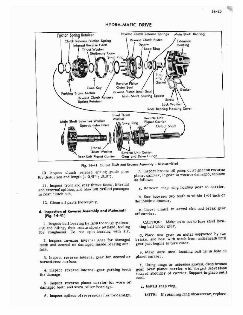
d, Inspection of Rey.ne Au.mbly anti MoinakaftFig, 14-411
inspect bail bearing by first thnraugidycleaning and oiling, then rntatrt slowly by hand, feelingfar rnughness- Do not spiti bearimig with air.
2. Inapect rsverse internal gear for damagedteeth and scored or damagedinside bearingaurfscc.
3. lnepect reverse internal gear for scoredorhurncd.coaesurface
4. Inspectfor dairsage
reverse internal gear parkiitg teeth
, Inspect reverse planet carrier for worn orm]armiagedteeth andworm, roLler bearings,
7, Inspect hrumtr oil pump drive gearan rsverseplanet carrier, II gear is worn or damaged,replaceas follows:
a. ltenvavc snap ring holding gear to carrier.
Saw beveen two teeth to within 1/64 Inch oftile inside diameter.
c. Insert chisel in sawsd slot and break gearoff cattier.
CAUTION: Make sure nat to lose sleek Inca -
ting hail under gear.
d. Place new gear on nettal supportedby twobricks and heat with torch from mlnderaeathantilgear just begins to torn color,
e. Make sure steel locating ball Is in hule inplaner earrlet.
Using tongs ar asbestosgloves, drop bronzegear over planet carrier with forged depreasionaward shoulder of carrier, Support in place until
g. Install snap ring
rripcn prine
14-25
ReerteClutch Re Iaese SptJns Mn in Shaft BannilRsetmeCimitch Piston
SpacerStap Ring
Sslsttivs Waths,SpesdomstsrDrive
Reve,ts Unit Ce,,trReor Unmt plo,,e Co ri 5 r Gaar end Drive Fl a
Fig. 14-41 Output Shdt ca Reystta Atternbly - OitauentId
6. lnapect splinesofrsvsraecarrier for damage, No-rE: Ii retainIng riltg shnwswear, replace.

14-26
HYDRA-/i&ATtC DRIVE
& Inspect reversecc’itcr gcar andflattgeassenthly far damnagudteeth or worn hoehing. fdaniagcd,replaceasscmnbly.The cenlcr gear is notfurnisitcdSeparaly.
9. Inapect output shalt a.s.can,hly for ecoredthrust and bearingstmrfacee.Fig, 14-41,
ID. Inspect output shift splines tar mmicka orburrs
-
Ii. Inspect ot:rpttt shaft apecdummteterdrive gearstirface for wear or damage,
12 Inspect steel end bronze rhrust washersforexcesaive wcar.
13, Inspect reverseintern-al gear thrustwasherfur wear or scoring.
14, Inspect reverse clutch release springretainer for sigJia or damageor burning.
1,5, Inspect reverse clutch stationary cone forhurtijng or excessivewear.
16. Inspect reverse piston coIl releasespringsfor distortion or *cnilapscd cuil.s, Iree lengtlt1-lI / 32’’.
I?. Ilispact reverse piston for burmting oil camsesurface.
IL Inspect reverseplaton for scoreson pi.ston -
Be sure oil seal ttt,ves are thoroughly clean-
19, Inspectfour reversepisromt pins for scorimig,loosenessor distortion.
20. Inspect inner and Outer pisto,i aceluparaLingsurfaces for scoring or roughness,
excessive wear and ace tim: oil holes in reLainerare open.
22. Lnspet’. mainsl,sft for damagedgear tcet’n,dir as: and hearing SI; rfacea-
13 Clean Ll parts tltotnLtghly.
14 Assembly of Individual Units
a, Assembly of Front Unit
I, PISL-e frtsnL unit drtcm oit bcoc.h with driveems Imp.
2. InstaLl four drive andfour driven plates intofront drum alrcr’matcly, starting with a compesi-tion plate,
NOTE: ln.stall driven plaLes wIth squarenotchesoverdram,, pitta. Also, apply Hydra.Maticfluid Lu face of each plate surfacees assembled,
3. Install six outer cloIc1 release and mc:,: eixittnc r elI, tcli release springs t I-rougl plates ir. LUsprittg holes uf drum,
4. Irsta II new im’m,e r brass expander imtto ringgroove in clutch d rlmmti wills expandittg lips dawt.
5. While holding hrass expamtder in position,work new inner pistol, rubber acerinLo ring grnnvewith lip down ttver hrqss epinder, Fig. i442.
NOTE: Work expanderwell backinn, positio,lunder seal so brass edgesare ant exposed.Before replacing largeouter seal tIn cltmtch piston,insLall the piston into We clutch druni to in-sore prnper instsllanomt amtd seating or new in
ner rubber seal and expander, Renrve clutchpiston and iaapect i:,I,er seal.
6, V!aco new large robber scsi over rentannular piatoji beyond seal grnovc-
7. Install new large brass expander in pistongroove with lips tLp.
8. While hoidimtg expander iti Fositiolt, workrubber sealwell into groove with lip *au.
NOTE: Work expanderwell backinto positionunder seaI so brass edges ore not exposed.
9, It matall p55 ton in to c lu tell drumn rcaLing onntmter rubber seal, Aug’s squaretmotclmes it’ piatumtwit], holes in drum. While applying slight handpresstmrc to piston, guide seal into bore with tlto
fiat aide of a IJI’LJLL screwdriver
Fig. 4-42 Installing Oil aaI and Eapottiemon Piston
21. Inspect rear bearing rekainer bushing ror

14-27
HYDRA-MATIC DRIVE
10. Install clutch drum and piston assemblyover front planet carrier into front unit drum.
11. Place carrier in press and press clutchdrum below snap ring groove. Install clutch drumsnapring, positioning gapof ringbetweentwodrivepin holes.
CAUTION: Snap ring must be well seatedinto grooveto preventinterferencewith ledgeon drum.
12. Releasepressandremoveassembly.
13. Tap front face of center gear with a rawhide or similar hammer so the clutch drum willseatagainstsnapring.
14. Insert intermediateshaft into drive platesand drum by rolling drum on bench while pressingcarrier firmly into the plates.
15. Placeplanet carrier and drum assemblyintoholding fixture.
16. Install bronze, then steel thrust washerover intermediateshaft.
NOTE: Locating lug on steel washer mustfit over flat portion of intermediate shaft.
17. Install snapring over intermediateshaftintogrooveabove steel washer.
CAUTION: Do not allow snap ring to scorebearingsurfaceof intermediateshaft.
b. Assembly of Rear Unit Fig. 14-33
I. Place the rear unit drum and internal gearassembly on the bench with the drive pins up.
2. Install eight drive and eight driven platesin the drum, alternating theplates.
NOTE: Start with a drive composition andfinish with a driven steel plate. Assembledriven plates with square notchesover drivepins. Apply Hydra-Made fluid to face of eachplate when installing.
3. Install six outer and six inner clutch releasesprings into the rounded cutouts in the steelclutch discs and into the holes in the drum. Install the sixreleasespring guidepins.
4. Position a new rubber seal on inner pistonof clutch drum above groove. Install a new brassexpander into ring groove of clutch drum withexpandinglips down.
5. While holding thebrassexpanderin position,work the rubber seal into ring groove with lipdown over brassexpander.
6. Place a new rubber seal over rear annularpiston beyond seal groove.
7. Install a new brassexpanderin piston groovewith the lips facing up. While holding expanderinposition, work rubber seal with lip up well intothegroove.
NOTE: Work expanderwell into position under seal so that edgeof expanderis not exposed.
8. Placepiston into clutch drum resting onouterrubber seal. Align square notches in piston withholes in clutch drum. While applying slight handpressure to piston, guide seal into bore with sideof a screwdriver.
9. Install rear clutch drum andpiston assemblyover drive pins into drum.
10. Place rear unit on a press and press theclutch drum until it is below the snapring groovein the drum. Install clutch drum snapring, positioning gap of ring betweentwo drive pin holes.
CAUTION: Snap ring must be well seatedin the groove to prevent interferencewith ledgeon drum.
11. Releasepressand remove assembly.
12. Tap front face of clutch drum using woodblock andhammer to seatthe clutch drum againstthe snapring.
13. Install front bronzethrust washer into deepcounterbore in rear clutch hub and retain withpetrolatum.
14. Install rear hub and thrust washer intoclutch drive plates.Rotate hub and drumon benchto meshsplines with teeth of plates.
15. Install rear clutch hub holding Tool, J-2l74,on rear drum to hold huh inplace.Useone reversedrive flange attachingscrew to hold tool.
16. Install oil delivery sleeveover intermediateshaft with long bearing up. Compressexposedoildelivery sleeverings with ring compressor,J-1537,and tap oil delivery sleeve into bore of frontclutch drum with plastic or similar hammer.Fig. 14-43.
NOTE: Staggerring gaps 1800 apart to minimize oil leakage.

14-28
HYDRA-MATIC DRIVE
5. I’,stall ruverse planet carrier over outputshaft with bronze drive gear down, meshingpininnsich sun gear. Be sure the unit is bottomed againstthe reverseplattet corner snap ring,,
6. IlmsLaII the reverse clutch releaseflat springand sp.ring retainer itt reverse interi,,,I gear onreverseinternal gear aide.
7. Install rovetse stationary cotic nIl reverselitternal gear cone. Usc large snap ring pliersto spread colic fttr installation’ being careful antto spread comic to euc.h an elteflt t.hat it will heconic cllstortedi Fig. 14-SI.
NOTE Sma]I dowr’l on entlo sltnutti pointtoward tocth ttn gear
s. Install large bronze thrusr washer overcollarof revcrse internal veer using pctrolaium to hoidthrasi washer in place.
IV, narall rear clutch hub IrunL snap ring intosecondgroove CI, intermediateshaft.
18, Compressexposudoil delivery sleeverin,install rear unii drum assembly on ititormnediaieshaft. Fig. 14-43.
19. Install rear clutch hub rear snap ring.
NOTE; Poth the front drum amtd rear drumshould be free to rotaie under slight farce. It’cither drum binds, the unit attould le disassembled and the causi: uf trnuhle corrected
C. A,,embly of Reven Unit
- Hold reverse center gear it, left hand withdrive finnge up; fnstuil the steel thrust washer,and titen ihe bronze thrust washer ii, the recessof the drive flange.
2. Still holdIng the reverse center gear in theleft hand, pick up the output shaft with the righthand, insert nutput shaft atmd through drive flangeand center goer until carrier bottoms on the tet,tlirust.wachers
-
.3. Holding drive flange and center gear tightlyagainst the carrier to keep thrust washersfromn,oving, set the output shaft and rho carrier ontable on the cerrier end.
4. ImlLaU reverse planet carrier .Ynap ring.
NOTE: a, not pick ap this unit until con,pletely assembled to prevent waehere fromslipping out or place,
9. Install reverse col,e piston inner seal withtip down.
to, Inat-aif outer oil aesl on reverseconepistoltwith seal Up toward flat sftle of piston.
11. Install piston in retainer hut do nnt lineupholes in pistn]t with dowels in retainer.
12. Jnstsli .12,5’’ shim stock ‘Foul Nn I _4752ibetween soul ond s-eralIter until it rests on ledgeof retainer. Fig. 14-44.
IS. Iterate piston until holes are lined up withdowel pi.s and press piston wn into retainer.
14. Remove shim,
IS Install the six reverse clutch roiense coil
Fi0. ‘4-42 InstallinG Uait Asse,ebly onInteta,ediate Shof I.
springs
Fly. 4-44 Inallina Rvers Cone 1kb,,