A Note on Integrals and Hybrid Contours in the Complex Plane

Abstract—In this paper it is presented a Hybrid Remote
Laboratory System (HRLS), which is a remote laboratory
focused in automatic control. The main objective of this
laboratory is to permit the users to learn to adjust predefined
controllers and to design their own controllers for testing them
later over a set of physical devices through Internet and analyze
their performance. The controllers designed by the users can
use S-Functions (Simulink-Functions) created using C
language; permitting the creation and implementation of
complex controllers in an easy and fast way. The HRLS uses
Matlab-Simulink for practice processing and the Real Time
Workshop Toolbox (RTW) such as real time kernel. The HRLS
lets to integrate new processes for carrying out controller tests.
At present three devices are available: a DC motor, a robot
manipulator and an electro pneumatic cylinder. The laboratory
has been used in identification and control theory in
postgraduate courses in Instituto Tecnológico de Minatitlan in
Mexico as well with Mechanical and Automatic Engineering
students in Universidad Central “Marta Abreu” de las Villas
and in Universidad de Cienfuegos, both located in Cuba.
Index Terms— Distance, hybrid, laboratory, matlab, remote,
simulink.
I. INTRODUCTION
The development of Web technologies has permitted to
incorporate some computational tools, such as Matlab and
Simulink, in distance education programs, being the
automatic control one of the technical areas that has greatly
exploited these new technologies for developing tools to
facilitate the distance learning. The Web-based new
technologies have allowed to give access to several devices
in a remote way through distance laboratories, which can be
classified into two great classes: virtual distance laboratories
and real distance laboratories. Virtual distance laboratories
are based on a physical system simulation in a remote way.
Here, through computer animation and the use of specialized
software, these physical systems can be represented in a
graphic and an analytical form.
Real distance laboratories are laboratories where the users
can interact with real devices in a remote way. Usually the
users can change some control parameters, make
experiments, see the results and download the experiment
Manuscript received January 1, 2013; revised March 22, 2013. This work
was supported in part by the Instituto Tecnológico de Minatitlan trust
program.
A. R. S. Castellanos, J. de J. M. Vázquez, R. A. Ortíz, and A. Zamudio
Radilla are with Electronic Engineering Department, Instituto Tecnológico
de Minatitlán, Blvd. Institutos Tecnológicos s/n, CP.96848, México (e-mail:
[email protected], [email protected],
[email protected], [email protected]).
data through a Web interface. These types of experiments are
used, for example in [1], where it is presented a distance
laboratory in the field of mechatronics; in [2] it is described a
laboratory for controlling a wide variety of devices and in [3]
are available some robot control experiments.
At present, the tendency in the development of distance
laboratories is to integrated real distance and virtual distance
laboratories in a unique hybrid distance or remote laboratory;
and letting the users to develop their own controllers in a
remote way. In such laboratories the complexity in the
hardware and software design is drastically increased. An
example of this is the case of the system presented in [4],
where it is described an hybrid laboratory where users can
development and test new control algorithms in systems such
as a rotary inverted pendulum, fan and plate system, triple
tank systems and others. In [5] is presented a distance
laboratory that allows the creation of controllers in a remote
way using the Labview environment for carrying out heater
control experiments, while in [3] the same approach is used
for design new control algorithms applied in mobile robots.
This article describes the design and implementation of a
hybrid remote laboratory focused in the automatic control
study. The Hybrid Remote Laboratory System (HRLS) lets
the users to change the references, modify the control
parameters and design their own controllers in a simple way
using very well-known tools in the automatic control field
such as Matlab and Simulink. One of the main features of
HRLS is that the remote users can create controllers using the
blocks given by Simulink, as well as to incorporate
S-Functions defined by the users in C language. This makes
possible to test complex controllers in a simple way and using
the most modern techniques of Computer Aided Control
Systems Design (CACSD).
II. HRLS ARCHITECTURE
The HRLS is divided into three parts: User interface,
practices management and practices processing as shown in
Fig. 1.
Fig. 1. Software and hardware level architecture of HRLS.
Hybrid Remote Laboratory for Testing New, Complex and
Advanced Controllers
Aldo R. Sartorius Castellanos, Member, IACSIT, José de J. Moreno Vázquez, Raúl Antonio Ortíz, and
Antonia Zamudio Radilla
337DOI: 10.7763/IJMMM.2013.V1.73
International Journal of Materials, Mechanics and Manufacturing, Vol. 1, No. 4, November 2013
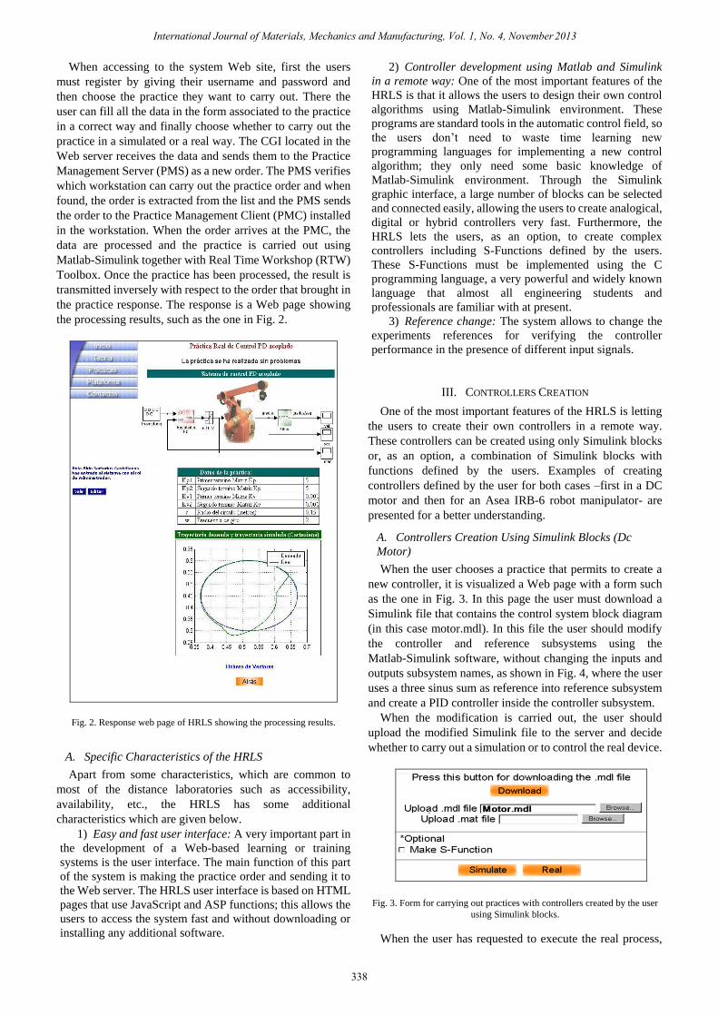
When accessing to the system Web site, first the users
must register by giving their username and password and
then choose the practice they want to carry out. There the
user can fill all the data in the form associated to the practice
in a correct way and finally choose whether to carry out the
practice in a simulated or a real way. The CGI located in the
Web server receives the data and sends them to the Practice
Management Server (PMS) as a new order. The PMS verifies
which workstation can carry out the practice order and when
found, the order is extracted from the list and the PMS sends
the order to the Practice Management Client (PMC) installed
in the workstation. When the order arrives at the PMC, the
data are processed and the practice is carried out using
Matlab-Simulink together with Real Time Workshop (RTW)
Toolbox. Once the practice has been processed, the result is
transmitted inversely with respect to the order that brought in
the practice response. The response is a Web page showing
the processing results, such as the one in Fig. 2.
Fig. 2. Response web page of HRLS showing the processing results.
A. Specific Characteristics of the HRLS
Apart from some characteristics, which are common to
most of the distance laboratories such as accessibility,
availability, etc., the HRLS has some additional
characteristics which are given below.
1) Easy and fast user interface: A very important part in
the development of a Web-based learning or training
systems is the user interface. The main function of this part
of the system is making the practice order and sending it to
the Web server. The HRLS user interface is based on HTML
pages that use JavaScript and ASP functions; this allows the
users to access the system fast and without downloading or
installing any additional software.
2) Controller development using Matlab and Simulink
in a remote way: One of the most important features of the
HRLS is that it allows the users to design their own control
algorithms using Matlab-Simulink environment. These
programs are standard tools in the automatic control field, so
the users don’t need to waste time learning new
programming languages for implementing a new control
algorithm; they only need some basic knowledge of
Matlab-Simulink environment. Through the Simulink
graphic interface, a large number of blocks can be selected
and connected easily, allowing the users to create analogical,
digital or hybrid controllers very fast. Furthermore, the
HRLS lets the users, as an option, to create complex
controllers including S-Functions defined by the users.
These S-Functions must be implemented using the C
programming language, a very powerful and widely known
language that almost all engineering students and
professionals are familiar with at present.
3) Reference change: The system allows to change the
experiments references for verifying the controller
performance in the presence of different input signals.
III. CONTROLLERS CREATION
One of the most important features of the HRLS is letting
the users to create their own controllers in a remote way.
These controllers can be created using only Simulink blocks
or, as an option, a combination of Simulink blocks with
functions defined by the users. Examples of creating
controllers defined by the user for both cases –first in a DC
motor and then for an Asea IRB-6 robot manipulator- are
presented for a better understanding.
A. Controllers Creation Using Simulink Blocks (Dc
Motor)
When the user chooses a practice that permits to create a
new controller, it is visualized a Web page with a form such
as the one in Fig. 3. In this page the user must download a
Simulink file that contains the control system block diagram
(in this case motor.mdl). In this file the user should modify
the controller and reference subsystems using the
Matlab-Simulink software, without changing the inputs and
outputs subsystem names, as shown in Fig. 4, where the user
uses a three sinus sum as reference into reference subsystem
and create a PID controller inside the controller subsystem.
When the modification is carried out, the user should
upload the modified Simulink file to the server and decide
whether to carry out a simulation or to control the real device.
Fig. 3. Form for carrying out practices with controllers created by the user
using Simulink blocks.
When the user has requested to execute the real process,
338
International Journal of Materials, Mechanics and Manufacturing, Vol. 1, No. 4, November 2013

the HRLS first makes a system simulation and, based on the
data obtained from the simulation, several tests are made to
determine if the controller can be implemented in the real
system. In the DC motor these tests are intended to determine
if the system shows high-frequency oscillations that can be
either a mechanical or a temperature risk for the motor. Once
it has been determined that there are no risks for the motor,
the HRLS is in charge of implementing the controller,
compiling the system using the RTW Toolbox and carrying
out the practice in real time. If the HRLS detects that the
designed controller represents a risk for the motor, the user is
informed the cause and is given the simulation graphs and
data performed so that he can inspect the system
performance.
Fig. 4. Reference and PID controller implemented by the user using Simulink
blocks for controlling a direct current motor.
B. Controllers Creation Using Simulink Blocks and
S-Functions Defined by the User (Robot Manipulator)
Through this functionality the HRLS allows the creation of
complex controllers which use Simulink blocks and
S-Functions written in C language. When the user selects a
practice with the possibility to create a controller and to make
active the S-Function creation check box, he is shown a Web
page that contains a form similar to the one shown in Fig. 3,
but with five additional fields as shown in Fig. 5, which are
referred to below.
1) Name: In this field the S-Function name should be
specified. This will be the block name defined by the user.
2) Inputs: It specifies the number of multiplexed inputs that
will enter the block defined by the user.
3) Outputs: It specifies the number of demultiplexed outputs
that will get out of the block defined by the user.
4) Main function: Here the user should write the S-function
code specifying the block inputs defined by the user as
u[0], u[1]…u[n] and the outputs as y[0], y[1]...y[n]. This
code should be written in C language.
5) Auxiliary functions: Here the user can write the auxiliary
functions declaration which will be called from the main
function. This code should be written in C language.
As in the previous example, in this Web page the user
should download a Simulink file containing the practice
block diagram (in this case Robot.mld). In this file the user
should modify the controller subsystem using the
Matlab-Simulink software without modifying the inputs and
outputs name as shown in Fig. 6, where the user has
implemented a PD controller with adaptive compensation
proposed in [6].
Fig. 5. Form for carrying out practice with a controller created by the user
using Simulink blocks and S-Functions defined by the user.
This controller uses a user-defined function through an
S-Function called “Adaptive” in the controller subsystem. In
the five additional fields of the form the user must write the
S-Function name (Adaptive in this case), the inputs number
(10 inputs), the outputs number (2 outputs) and the main
function code as well as the auxiliary functions code, as
shown in Fig. 5.
Fig. 6. PD with an adaptive compensation controller implemented by the user
using Simulink blocks and S-Function for controlling an Asea IRB-6 robot
manipulator.
Once the modification is carried out and the S-Function
specified, the user must upload the modified Simulink file to
the server and decide whether to carry out a simulation or to
control the real device. When the HRLS is commanded to
control the real device, it first makes a system simulation and,
based on the data obtained from the simulation, several tests
are made to determine whether the controller can be
339
International Journal of Materials, Mechanics and Manufacturing, Vol. 1, No. 4, November 2013

implemented in the real device. In the robot manipulator
these tests are focused in three aspects:
1) Verify that the Cartesian trajectory should not
surpass the robot manipulator workspace.
2) Confirm that the link positions should not exceed
the mechanical limits of each link.
3) Analyze, through a signal frequency spectrum
analysis, that the system should not present
high-frequency oscillations that can mechanically
misadjust the robot manipulator and/or damage its
actuators.
Once these aspects have been determined, the HRLS
implements the controller, compiles the system using the
RTW Toolbox and carries out the practice in real time. In
case the HRLS detects that the designed controller represents
a risk for the robot manipulator, the user is informed about
the cause and is given the simulation graphs and data
performed so that he can inspect the system performance.
IV. TEACHING EXPERIENCE USING HRLS
At present the HRLS has been used in different practices in
identification and control courses for Mechanical
Engineering and Automatic Engineering students in
Universidad Central “Marta Abreu” de las Villas and in
Universidad de Cienfuegos, both located in Cuba.
The most stimulating aspects for the students were that
they could evaluate the differences that exist between
mathematical models and real devices and that they carry out
practices not only at any schedule if not also an unlimited
number of times. These practices have been carried out with
small groups (usually 15 students) and, in less than 45
minutes, 15 to 20 practices are carried out, which shows the
high rate in exploitation of the equipment when accessing
remotely using the HRLS.
In Mexico the HRLS has been used in Institute
Tecnológico de Minatitlan in identification, control theory
and robotics in undergraduate and postgraduate courses for
implement fuzzy, neural networks and other advance
controllers. When using the HRLS, the users can confirm that
they are able to design and evaluate the performance, of
almost any controller, on real devices in a remote way, which
reduces notably the time and effort required in the
experimental validation phase of new controller proposals.
At present we are working in the creation of a
methodological base, that help us in the construction and use
of practices, as well as in the design of a feedback system that
allows the users interact with the HRLS in a more effective
way, which will allow to know the impact that the system has
in the learning of the users, also that will serve as a via for the
proposal of improvements to the system.
V. CONCLUSION
The Hybrid Remote Laboratory System (HRLS) gives the
users the facility of using packets such as Matlab and
Simulink together with the RTW Toolbox for the creation
and testing of controllers in real devices in a remote way.
Through this mechanism it is possible to implement
controllers that use complex algorithms which can be easily
created using the power and flexibility given by both the C
language and the S-Functions.
Since the system software is easily adaptable for new
processes, the incorporation of new devices for testing
controllers can be easily accomplished. At present the HRLS
has a DC permanent magnet servomotor series PI 8.03,
developed by Dynamo-SL connected to an incremental
encoder with 10,000 pulses per revolution of precision, an
Asea IRB-6 robot manipulator with five degrees of freedom
with incremental encoders with 10,000 pulses per revolution
and a Megliani 40.400 electro pneumatic cylinder equipped
with a Festo MPYE-5-1/8-HF valve, and an LX-EP-40
incremental encoder that has 2.44 pulses per millimeter. We
are currently working for the future incorporation of new
processes including experiments for controlling level,
pressure and temperature in tanks, flow in pipes, and PH, as
well as the future incorporation of a better feedback to the
user through Java technology which can make the system
more interactive and more encouraging for the users.
REFERENCES
[1] D. Perdukova and P. Fedor, "A Virtual Laboratory for the study of
Mechatronics," presented at 9th IEEE International Conference on
Emerging eLearning Technologies and Applications (ICETA), Tatras,
Slovenia, 2011.
[2] M. Tawfik, E. Sancristobal, S. Martín, C. Gil, P. Losada, G. Díaz, and
M. Castro, "Remote Laboratories for Electrical & Electronic Subjects
in New Engineering Grades," presented at Promotion and Innovation
with New Technologies in Engineering Education (FINTDI), Teruel,
Spain, 2011.
[3] M. R. Kadhum and S. Kadry, "New design of robotics remote lab," in Proc. International Journal of Advanced Computer Science and
Applications (IJACSA), vol. 3, 2012.
[4] X. Cao and S. A. Zhu, "iEELab Practice: A Hybrid Remote Laboratory
for Distance Education in Electrical Engineering," presented at 5th
International Conference on Computer Science & Education, Hefei,
China, 2010.
[5] K. M. Moudgalya and I. Arora, "A Virtual Laboratory for Distance
Education," presented at International Conference on Technology for
Education, Mumbai, India, 2010.
[6] J. J. Slotine and W. Li,
R. S. Castellanos was born in Xalapa, Veracruz,
México. He is graduated from Universidad
Veracruzana, in Xalapa, México (Electromechanical
Engineering) in 2000. He has an MSc in Automatics
with speciality in Computational Systems from
Universidad Central “Marta Abreu” de Las Villas in
Cuba in 2002. He received the Ph.D. degree in
Automatic Control from Universidad Central “Marta
Abreu” de Las Villas in Cuba in 2005Dr. Sartorius is member of
International Society of Automation (ISA) and his interests include adaptive
control systems, remote laboratories and robotics.
J. de J. M. Vázquez was born in Coatzacoalcos,
Veracruz, México in 1969. He studied Electronic and
Instrumentation Engineering at the Minatitlan
Institute of Technology, Veracruz, México graduated
in 1995. He received the Electronic Engineering
(M.Sc) degree from National Center for Research and
Technological Development, Cuernavaca, Morelos,
México in 1996. He received the Ph.D. degree in
Bioengineering Electronics with emphasis on
Bioelectronics from Valencia Polytechnic University, Spain, in 2011. He is
professor at the Technological Institute of Minatitlan, Veracruz, México
since 1996. Dr. Moreno is Chief of Research Projects at Department of
Electronic Engineering and Secretary of the faculty Master of Engineering
program. Some of his research interests are gastroenterology specifically in
the identification and quantification of electroenterogram as intestinal
Author’s formal
photo
340
Applied nonlinear control, 1991.
International Journal of Materials, Mechanics and Manufacturing, Vol. 1, No. 4, November 2013

motility diagnostic tool, digital electronics, digital signal processing, spectral
estimation and Instrumentation and Control.
R. A. Ortíz was born in Coatzacoalcos, Veracruz,
México in 1965. He studied Electronic and
Instrumentation Engineering at the Minatitlan
Institute of Technology, Veracruz, México graduated
in 1991. He received the Electronic Engineering
(M.Sc) degree from National Center for Research and
Technological Development, Cuernavaca, Morelos,
México in 1995. He is professor at the Technological
Institute of Minatitlan, Veracruz, México since 1995.
M.Sc Ortiz is Chief of electronics laboratory at Department of Electronic
Engineering and professor of the faculty Master of Engineering program.
Some of his research interests are power electronics, photovoltaic panels
applied to battery charging, Electronic lighting systems, remote laboratories,
Instrumentation and Control.
A. Z. Radilla was born in Distrito Federal, México. She
is graduated from Instituto Tecnológico de Minatitlán, in
Veracruz, México, graduated in 1988 in Electronic
Engineering. She has recieved Mdu degree in Educatión
from Universidad Iberoaméricana Golfo Centro Puebla
México in 2012. She has worked in C.P. Cangrejera in
Petróleos Mexicanos PEMEX Company in the field of
automation and control in Coatzacoalcos Veracruz,
México. Since year 1984 she has been working as a full
time professor in electronic engineering carreer at Instituto Tecnológico de
Minatitlan in México. Since year 1992 she has been working as professor in
Universidad Veracruzana in Minatitlan, Mexico.Mdu. Zamudio is member of
Institute of Electrical and Electronics Engineers (IEEE) and his interests
include Analog Electronic and Education.
341
International Journal of Materials, Mechanics and Manufacturing, Vol. 1, No. 4, November 2013